Application description 05/2016 Plant Data Interface for ...
43
https://support.industry.siemens.com/cs/ww/en/view/86302104 Application description 05/2016 Plant Data Interface for the Food & Beverage Industry Interface description based on Weihenstephan Standards
Transcript of Application description 05/2016 Plant Data Interface for ...

https://support.industry.siemens.com/cs/ww/en/view/86302104
Application description 05/2016
Plant Data Interface for the Food & Beverage Industry Interface description based on Weihenstephan Standards

Warranty and liability
Plant Data Interface - Weihenstephan Entry-ID: 86302104, V2.0, 05/20162016 2
S
iem
en
s A
G 2
01
6 A
ll ri
gh
ts r
ese
rve
d
Warranty and liability
Note The Application Examples are not binding and do not claim to be complete regarding the circuits shown, equipping and any eventuality. The Application Examples do not represent customer-specific solutions. They are only intended to provide support for typical applications. You are responsible for ensuring that the described products are used correctly. These Application Examples do not relieve you of the responsibility to use safe practices in application, installation, operation and maintenance. When using these Application Examples, you recognize that we cannot be made liable for any damage/claims beyond the liability clause described. We reserve the right to make changes to these Application Examples at any time without prior notice. If there are any deviations between the recommendations provided in these Application Examples and other Siemens publications – e.g. Catalogs – the contents of the other documents have priority.
We do not accept any liability for the information contained in this document. Any claims against us – based on whatever legal reason – resulting from the use of the examples, information, programs, engineering and performance data etc., described in this Application Example shall be excluded. Such an exclusion shall not apply in the case of mandatory liability, e.g. under the German Product Liability Act (“Produkthaftungsgesetz”), in case of intent, gross negligence, or injury of life, body or health, guarantee for the quality of a product, fraudulent concealment of a deficiency or breach of a condition which goes to the root of the contract (“wesentliche Vertragspflichten”). The damages for a breach of a substantial contractual obligation are, however, limited to the foreseeable damage, typical for the type of contract, except in the event of intent or gross negligence or injury to life, body or health. The above provisions do not imply a change of the burden of proof to your detriment. Any form of duplication or distribution of these Application Examples or excerpts hereof is prohibited without the expressed consent of the Siemens AG.
Security informa-tion
Siemens provides products and solutions with industrial security functions that support the secure operation of plants, systems, machines and networks. In order to protect plants, systems, machines and networks against cyber threats, it is necessary to implement – and continuously maintain – a holistic, state-of-the-art industrial security concept. Siemens’ products and solutions only form one element of such a concept. Customer is responsible to prevent unauthorized access to its plants, systems, machines and networks. Systems, machines and components should only be connected to the enterprise network or the internet if and to the extent necessary and with appropriate security measures (e.g. use of firewalls and network segmentation) in place. Additionally, Siemens’ guidance on appropriate security measures should be taken into account. For more information about industrial security, please visit http://www.siemens.com/industrialsecurity.
Siemens’ products and solutions undergo continuous development to make them more secure. Siemens strongly recommends to apply product updates as soon as available and to always use the latest product versions. Use of product versions that are no longer supported, and failure to apply latest updates may increase customer’s exposure to cyber threats. To stay informed about product updates, subscribe to the Siemens Industrial Security RSS Feed under http://www.siemens.com/industrialsecurity.
Table of Contents
Plant Data Interface - Weihenstephan Entry-ID: 86302104, V2.0, 05/20162016 3
Cop
yri
gh
t
Sie
me
ns A
G 2
01
6 A
ll ri
gh
ts r
ese
rve
d
Table of Contents Warranty and liability ................................................................................................... 2
1 Overview of a plant wide automation concept ............................................... 4
1.1 Overview of Plant Wide Concepts for food and beverage industry ................................................................................................. 4
1.2 Layout overview for plant wide data interface ...................................... 4 1.3 Definitions ............................................................................................. 5 1.3.1 Default values ....................................................................................... 5 1.3.2 Data types ............................................................................................ 6 1.4 PDI Overview ....................................................................................... 7 1.4.1 PDI Basic .............................................................................................. 7 1.4.2 PDI LCU ............................................................................................... 7 1.4.3 PDI PEC ............................................................................................... 8 1.4.4 PDI Para ............................................................................................... 8
2 Interface description based on Weihenstephan Standards .......................... 9
2.1 PDI Basic .............................................................................................. 9 2.1.1 Interface description overview ............................................................ 10 2.1.2 Detailed interface description ............................................................. 11 2.2 PDI LCU ............................................................................................. 18 2.2.1 Interface description overview ............................................................ 19 2.2.2 Detailed interface description ............................................................. 20 2.3 PDI PEC ............................................................................................. 24 2.3.1 Interface description overview ............................................................ 25 2.3.2 Detailed interface description ............................................................. 27 2.4 PDI Para ............................................................................................. 31 2.4.1 Interface description overview ............................................................ 31 2.4.2 Detailed interface description ............................................................. 32
3 General PDI Information.................................................................................. 34
3.1 Technical Implementation .................................................................. 34 3.1.1 STEP 7 (S7-300 / S7-400) ................................................................. 34 3.1.2 TIA Portal (S7-300 / S7-400 / S7-1200 / S7-1500) ............................ 34 3.1.3 SIMOTION SCOUT ............................................................................ 35 3.2 State description ................................................................................. 35 3.3 Cross naming reference (system wide) .............................................. 39
4 Abbreviations ................................................................................................... 42
5 Related literature ............................................................................................. 43
6 History............................................................................................................... 43
1 Overview of a plant wide automation concept
Plant Data Interface - Weihenstephan V2.0, Entry-ID: , 05/20162016 4
Cop
yri
gh
t
Sie
me
ns A
G 2
01
6 A
ll ri
gh
ts r
ese
rve
d
1 Overview of a plant wide automation concept
1.1 Overview of Plant Wide Concepts for food and beverage industry
In the Food & Beverage Industry is substantial room for improvement, to increase the efficiency and effectiveness of existing and new production lines.
An essential component to increased efficiency is the integration of production lines and machines, from inbound raw material, through production, packaging and outbound logistics. This integration allows for the recording of essential production parameters, such as quantity produced, machine up-time, etc., which can then be analyzed on upper-level systems, in order to identify measures for improvement.
Today, this task comes with significant effort, as the data is collected from the machines and components of disparate manufacturers, who all provide various levels of data, through a number of different forms. The plant wide automation concept for line integration from Siemens helps by offering standard data interfaces which help give direction to end customers, machine builders and integrators looking to integrated lines. These interfaces provide a coherent collection of data that can be provided to upper level line monitoring, Line HMI and enterprise level systems. The definition of one such interface, for the Weihenstephan standard, is described herein.
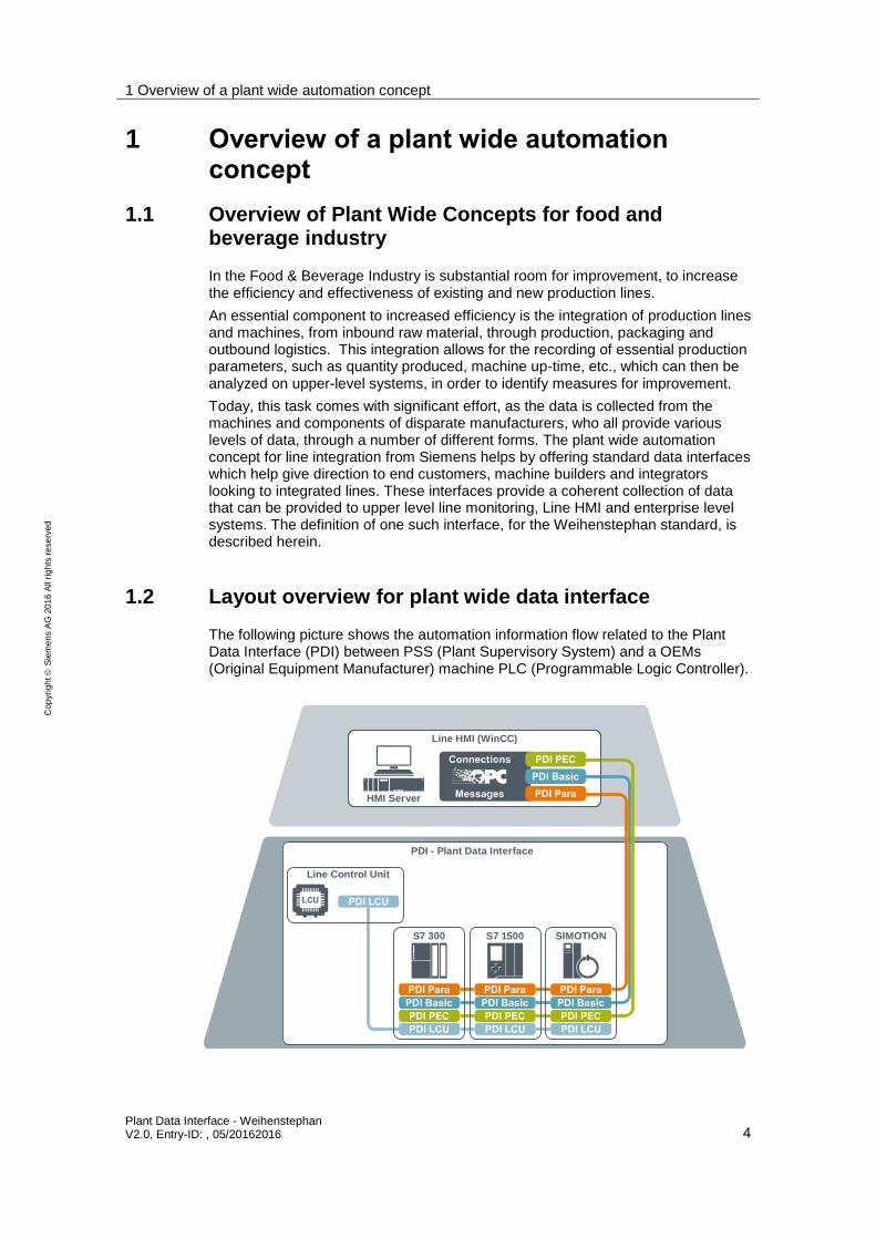
1.2 Layout overview for plant wide data interface
The following picture shows the automation information flow related to the Plant Data Interface (PDI) between PSS (Plant Supervisory System) and a OEMs (Original Equipment Manufacturer) machine PLC (Programmable Logic Controller).
PDI - Plant Data Interface
S7 1500S7 300 SIMOTION
Line Control Unit
Line HMI (WinCC)
HMI Server

1 Overview of a plant wide automation concept
Plant Data Interface - Weihenstephan V2.0, Entry-ID: , 05/20162016 5
Cop
yri
gh
t
Sie
me
ns A
G 2
01
6 A
ll ri
gh
ts r
ese
rve
d
The data interface, named PDI Basic, provides the necessary information for Line Visualization and Line Monitoring (LM).
The PDI Basic is available in 2 different versions. One version is available based on the Weihenstephan Standards which is described here and another version for OMAC (Organization for Machine Automation and Control) is described in additional interface documentation.
1.3 Definitions
1.3.1 Default values
All values and counters that are not used or cannot be provided due to an out-of-range or undefined condition have to be set to “–1” or in case of the type STRING to “”. Counters are always “0” or positive.

1 Overview of a plant wide automation concept
Plant Data Interface - Weihenstephan V2.0, Entry-ID: , 05/20162016 6
Copyright Siemens AG 2016 All rights reserved
1.3.2 Data types
Type
Used in this document
Description OMAC Weihenstephan S7-Type SIMOTION HMI-Type OPC SIMATIC NET
LM/MES/MOM
S7-3xx/4xx S7-1x00 WinCC DM TIA Portal
S7-3xx/4xx S7-1x00
DINT Integer with 32bit
Int(32) Signed32 DINT Dint DINT Signed 32-bit value
Dint Int32
LONG
UDINT Integer with 32bit (positive values only)
n.a. Unsigned32 DWORD UDint UDINT Unsigned 32-bit value
UDint UInt32 ULONG
REAL 32bit floating number
REAL REAL REAL Real REAL Floating-point 32-bit
Real Float REAL
BIT[x]
32bit variable were each bit is interpreted as on unique value 0 or 1
Bool struct
n.a. workaround: use only first bit in Hex32
DWORD each single bit can be addressed
DWORD each single bit can be addressed
DWORD each single bit can be addressed
Binary tag Bool UInt32 BOOL array dimension = 32
DWORD 32 bit double word
n.a. Hex32 DWORD DWord DWORD Unsigned 32-bit value
DWord UInt32 ULONG
BOOL Variable 0 or not 0
Bool n.a. BOOL Bool BOOL Binary tag Bool Boolean BOOL
STRING
String limited to the number of characters in [num. of characters] ASCII only
String n.a. STRING[x] String[x] STRING[x] Text tag 8-bit
String[x] String STRING dimension = X
STRING16 16 bit simple Unicode
n.a. String16 n.a. n.a n.a. Text tag 16-bit
n.a n.a. STRING dimension = X

1 Overview of a plant wide automation concept
Plant Data Interface - Weihenstephan V2.0, Entry-ID: 86302104 7
Cop
yri
gh
t
Sie
me
ns A
G 2
01
6 A
ll ri
gh
ts r
ese
rve
d
1.4 PDI Overview
1.4.1 PDI Basic
The basic interface provides basic information regarding the machine, e.g. mode and state, machine speed and counters. The flow of information through the interface is from machine/production level (OEM) upwards to the LCU and/or PSS respectively. There is no data transfer from upper level LCUs/PSSs downwards to the machine/production level (OEM). This information is used for:
Operator information about the machine state for line overviews (HMI), on a line server or an HMI client in a control room.
Line monitoring for basic OEE / KPI (Overall Equipment Effectiveness / Key Performance Indicators) information.
All data exchanged with the PDI Basic are tag based and can be polled by the upper level at any time. The data itself can be written to the interface e.g. as data block in any PLC cycle. All data should however be written simultaneously to the interface to ensure consistency of data.
1.4.2 PDI LCU
The LCU interface provides additional data for line control functionality, e.g. start/stop and set line speed. Machine state information is communicated upwards from machine/production level (OEM) up to the LCU and/or PSS. Control and command data such as machine speed and start/stop are transmitted downwards from upper level LCUs/PSSs to the machine/production level (OEM).
The data are used…
to provide operator information about machine speed and entry/exit buffer of single machines on line overview (HMI) screens, on line servers or at HMI clients in a control room
by the Line Control Unit to control the line, in terms of speed, buffer fill-levels and start/stop of machines
All data exchanged with the PDI LCU between line HMI (PSS) and the OEM PLC are tag based and can be polled by upper level systems at any time. Transfer of data between the Line Control Unit and OEMPLC should be performed block-wise to ensure data consistency.
Implementation of the PDI LCU is only required for systems implementing the Line Control Unit. The LCU is an additional package for a plant wide automation that requires additional hardware and software components.
1 Overview of a plant wide automation concept
Plant Data Interface - Weihenstephan V2.0, Entry-ID: 86302104 8
Cop
yri
gh
t
Sie
me
ns A
G 2
01
6 A
ll ri
gh
ts r
ese
rve
d
1.4.3 PDI PEC
The PEC provides additional data for energy monitoring and on top level to support implementation of a corporate energy data management system with following objectives.
Compliance and support of national and international sustainability programs and standards, like ISO50001
Continuous improvement of energy and water conservation
Reduce costs for procurement of energy and water
Increase employee awareness for energy efficiency
All data exchanged with the PDI-PEC between line HMI (PSS) and the OEM PLC are tag based and can be polled by upper level systems at any time. An implementation of the PDI PEC is optional.
1.4.4 PDI Para
The PDI-Para interface provides additional data for machine specific parameters.
The information can be delivered Integer, Real or String values. The delivered information’s contain typically unit specific, process, order or reporting information’s. The implementation of the PDI Para is optional.

2 Interface description based on Weihenstephan Standards
Plant Data Interface - Weihenstephan V2.0, Entry-ID: 86302104 9
Cop
yri
gh
t
Sie
me
ns A
G 2
01
6 A
ll ri
gh
ts r
ese
rve
d
2 Interface description based on Weihenstephan Standards
2.1 PDI Basic
The basic interface provides basic information regarding machine state and parameters. The information is communicated upwards from machine/production level to the PSS level. There is no data transfer from upper level PSS systems downwards to the machine/production level.
This information is used for:
Operator information about machine state on line overview (HMI) screens, on line servers or on HMI clients in a control room. This includes:
– machine state and mode information
– material state information related to the machine
– alarm information
Line monitoring of basic OEE / KPI information
– production results (downtime information, OEE, global efficiency)
– raised alarm hit list
– MTTR (Mean time to repair) MTBF (Mean time between failures)
– KPI trends
All data exchanged via PDI Basicare tag based and can be polled by the upper level at any time. The data itself can be written to the interface e.g. as a data block in any PLC cycle. However all data should be written simultaneously to the interface.
NOTE If using TCP/IP communication (e.g. Weihenstephan Protocol) there shall be no access to the data while the communication is active.

2 Interface description based on Weihenstephan Standards
Plant Data Interface - Weihenstephan V2.0, Entry-ID: 86302104 10
Copyright Siemens AG 2016 All rights reserved
2.1.1 Interface description overview
The interface based on Weihenstephan Standard V08.
Parameter Number
Parameter Name Type WS Man- datory
Description
00030 SIE_Ver_BASIC String16[10] PDI version info. “PDI V2.0.0” fix for this implementation
00031 SIE_Ver_Proj_BASIC String16[10] Project specific version
00200 WS_Cur_Prog DWord Program indicates the current program code = Unit mode
00300 WS_Cur_State DWord Operating state related to the machines state model
00402 WS_Set_Mach_Spd REAL Set machine speed in primary units/minute
00401 WS_Cur_Mach_Spd REAL Current machine speed in primary units/minute
59900 SIE_Mach_Cum_Time DINT Machine Cumulative Time powered up - in hours
59901 SIE_Cons_Electricity DINT Consumed electrical energy in kWh
10001 SIE_Not_Of_Fail_Group DINT Message group as according to OMAC simplify Reason Code definition
10000 WS_Not_Of_Fail_Code DWord Notice of failure code (OEM specific)
00701 WS_Prod_Ratio DWord Package Ratio in primary pieces
05000 SIE_Prod_Ratio_Typ DINT Machine type: 1=depacker, 0=packer: Packer will be default
00190 SIE_Light_Stack DWord Represents the machine light stack with different color levels
59902 SIE_Tot_Packages DWord Resettable counter of total packages processed by the production machine
50220 WS_Tot_Packages DWord Accumulated counter of total packages processed by the production machine
59903 SIE_Bad_Packages DWord Resettable counter of bad packages rejected by the production machine
50240 WS_Bad_Packages DWord Accumulated counter of bad packages rejected by the production machine
00403 WS_Mach_Design_Spd REAL Machine design speed in primary units/minute in the installed environment based on currently processed product

2 Interface description based on Weihenstephan Standards
Plant Data Interface - Weihenstephan V2.0, Entry-ID: 86302104 11
Co
pyri
gh
t
Sie
me
ns A
G 2
01
6 A
ll ri
gh
ts r
ese
rve
d
2.1.2 Detailed interface description
SIE_Ver_BASIC
Par.Nr. Name Type Comment
00030 SIE_Ver_BASIC String16[10] Version of the used plant data interface
This data point provides a vendor specific version description of the WS interface implementation. “PDI_V2.0.0” is fixed for this implementation. The provided DB are already predefined with this name.
SIE_Ver_Proj_BASIC
Par.Nr. Name Type Comment
00031 SIE_Ver_Proj_BASIC String16[10] Project specific version description
This data point provides a project specific version description of the WS interface implementation. Regarding the content there are no specifications determined.
WS_Cur_Prog
Par.Nr. Name Type Comment
00200 WS_Cur_Prog DWORD Current program of the machine
The value shows the current program of the machine. The following values are defined according to the Weihenstephan Mode & State model:
Table 2-1
Bit No.
Value Program Description
Binary integer
- 00000000 0 Undefined Undefined mode (No program or mode selected)
0 00000001 1 Production Machine is in the function production and is able to produce
1 00000010 2 Start up Machine starts up to get in production mode
2 00000100 4 Run Down Machine shuts down from production mode
3 00001000 8 Clean Machine runs cleaning process
4 00010000 16 Changeover Machined changes from one product to another
5 00100000 32 Maintenance Machine operates a maintenance program
6 01000000 64 Break Machine is in pause mode

2 Interface description based on Weihenstephan Standards
Plant Data Interface - Weihenstephan V2.0, Entry-ID: 86302104 12
Co
pyri
gh
t
Sie
me
ns A
G 2
01
6 A
ll ri
gh
ts r
ese
rve
d
WS_Cur_State
Par.Nr. Name Type Comment
00300 WS_Cur_State DWORD Current machine state
The value indicates the machine state related to the WS machine state model.
Bit Nr.
Value Operating State
Binary Integer
0 00000000 00000000 00000001 1 Stopped
1 00000000 00000000 00000010 2 Starting
2 00000000 00000000 00000100 4 Prepared
3 00000000 00000000 00001000 8 Lack
4 00000000 00000000 00010000 16 Tailback
5 00000000 00000000 00100000 32 Lack Branch Line
6 00000000 00000000 01000000 64 Tailback Branch Line
7 00000000 00000000 10000000 128 Operating
8 00000000 00000001 00000000 256 Stopping
9 00000000 00000010 00000000 512 Aborting
10 00000000 00000100 00000000 1024 Equipment Failure
11 00000000 00001000 00000000 2048 External Failure
12 00000000 00010000 00000000 4096 Emergency Stop
13 00000000 00100000 00000000 8192 Holding
14 00000000 01000000 00000000 16384 Held
15 00000000 10000000 00000000 32768 Idle
16 00000001 00000000 00000000 65536 Unholding
17 00000010 00000000 00000000 131072 Suspending
18 00000100 00000000 00000000 262144 Unsuspending
19 00001000 00000000 00000000 524288 Resetting
20 00010000 00000000 00000000 1048576 Clearing
For more details see chapter 3.2 State description.
WS_Set_Mach_Spd
Par.Nr. Name Type Comment
00402 WS_Set_Mach_Spd REAL Set point of the machine speed in primary pieces/minute
This tag represents the set point of the machine speed in primary pieces/minute. It is less than the value of WS_Mach_Design_Spd.

2 Interface description based on Weihenstephan Standards
Plant Data Interface - Weihenstephan V2.0, Entry-ID: 86302104 13
Co
pyri
gh
t
Sie
me
ns A
G 2
01
6 A
ll ri
gh
ts r
ese
rve
d
WS_Cur_Mach_Spd
Par.Nr. Name Type Comment
00401 WS_Cur_Mach_Spd REAL Actual machine speed in primary pieces/minute
This tag represents the actual machine speed in primary pieces/minute.
The following example is for a packaging line running at balanced line speed of 1200 bottles/minute. The specified UoM (Unit of Measurement) is chosen to correspond with that of the current count of the filler or labeler.
Machine Actual Pack Counts CurMachSpeed in UoM
Bulk Depalletizer 50 (24 pack equiv.) 1.200 bottles/min
Filler 1.200 1.200 bottles/min
Labeler 1.200 1.200 bottles/min
Packer 100 (12 packs) 1.200 bottles/min
The value is calculated cyclically at the machine level.
SIE_Mach_Cum_Time
Par.Nr. Name Type Comment
59900 SIE_Mach_Cum_Time DINT Accumulated machine powered up time
This parameter describes the accumulated machine powered up time in hours. The value starts counting as soon as the machine is switched on. There is an overflow to “0” at “2147483647”. This is a non-resettable counter and has to be retained during PLC start/stop and PLC power off.
SIE_Cons_Electricity
Par.Nr. Name Type Comment
59901 SIE_Cons_Electricity DINT Current consumed electrical energy
This Parameter describes the current consumed electrical energy in kWh without decimal places.

2 Interface description based on Weihenstephan Standards
Plant Data Interface - Weihenstephan V2.0, Entry-ID: 86302104 14
Co
pyri
gh
t
Sie
me
ns A
G 2
01
6 A
ll ri
gh
ts r
ese
rve
d
SIE_Not_Of_Fail_Group
Par.Nr. Name Type Comment
10001 SIE_Not_Of_Fail_Group DINT Alarm reason group ID
Alarms are reported via “SIE_Not_Of_Fail_Group”. This ID is related to the Appendix A1 Alarm codes (ANSI/ISA-TR88.00.02-2008). At a minimum, the simplified reason group fault code is to be provided. Should other alarm codes be available, they should be placed within the appropriate range (i.e. Safety Related faults identified with a value from 1-31).
Value Detailed reason group Simplified reason group fault code
0 Undefined
32 Safety related Machine internal reason
64 Operator action
256 Product related
512 Equipment fault
999 All other internal
2499 Machine ext. Upstream process reason Main product flow
3499 Machine ext. Downstream process reason
4499 Out of service (planned and unplanned)
4999 Branch- or sub-utility equipment Other external reasons
Most important to the alarm ID are the three main categories
Machine internal error (value 1 to 1999)
Machine upstream reason (value 2000 to 2999)
Machine downstream reason (value 3000 to 3999)
These categories, among other values, are needed for basic RCA (Root Cause Analysis). For line OEE/KPI calculation at least the simplified reason group fault codes are required.
The value is set as soon as the machine detects an error condition. The value is reset as soon the alarm is acknowledged.
After the “SIE_Not_Of_Fail_Group” is acknowledged a new alarm can be set.
NOTE There is a template prepared in the HMI part where the message creation is described:
https://support.industry.siemens.com/cs/ww/en/view/100744248

2 Interface description based on Weihenstephan Standards
Plant Data Interface - Weihenstephan V2.0, Entry-ID: 86302104 15
Co
pyri
gh
t
Sie
me
ns A
G 2
01
6 A
ll ri
gh
ts r
ese
rve
d
WS_Not_Of_Fail_Code
Par.Nr. Name Type Comment
10000 WS_Not_Of_Fail_Code DWORD Initial machine error
This parameter represents the initial machine error, when the machine exits the state “Operating”, regardless of cause. The error number has to be reset to “0” (= no error) as soon as the machine goes back to the “Operating” state. In the case that the initial error is not immediately known when the machine exits the “Operating” state, the value “0” will remain and has to be updated, as soon as the initial error is detected. The error codes are machine/OEM specific. The OEM should provide a list of possible error numbers and their description, in accordance with the Weihenstephan Standard along with the device description file. The file has to contain descriptions in English. If available, the list should contain additional languages.
This parameter is mainly used for operator information on line HMIs and for basic RCA (Root Cause Analysis).
WS_Prod_Ratio
Par.Nr. Name Type Comment
00701 WS_Prod_Ratio DWORD Production ratio (sec.pieces/prim.pieces)
The tag WS_Prod_Ratio gives the ratio between exit items (secondary pieces) for the machine and primary pieces of the line.
The value contains the number of primary packages included in the current produced secondary packages. To give an example:
Packer packs six packs from single bottles Value = 6
Depacker empties one crate (20 bottles) into single bottles Value = 20
Palletizer empties one pallet (32 crates) into single bottles Value = 640
Together with “Status.Parameter3.Value” it will be defined if the machine is a packer or an unpacker.
SIE_Prod_Ratio_Typ
Par.Nr. Name Type Comment
00401 SIE_Prod_Ratio_Typ DINT Machine Is a packer or a unpacker
This tag indicates if the machine packs or unpacks pieces. 1=depacker, 0=packer. Packer will be set as default.

2 Interface description based on Weihenstephan Standards
Plant Data Interface - Weihenstephan V2.0, Entry-ID: 86302104 16
Co
pyri
gh
t
Sie
me
ns A
G 2
01
6 A
ll ri
gh
ts r
ese
rve
d
SIE_Light_Stack
Par.Nr. Name Type Comment
00190 SIE_Light_Stack DWORD Machine signal light stack
The machine light stack provides easy indication of the machine state for operators, based on EN / IEC 60204-1.
Color Meaning Description and operator task Light Signal
Red Emergency Hazardous condition.
Immediate action to deal with hazardous condition (e.g. switch off Energy supply).
Static Bit[0]
Flashing Bit[1]
Yellow Abnormal Abnormal condition impending critical conditions.
Monitoring and/or intervention (e.g. by reestablishing intended function).
Static Bit[2]
Flashing Bit[3]
Blue Mandatory Indication of a condition that requires an operator
action. Static Bit[4]
Flashing Bit[5]
Green Normal Normal condition Static Bit[6]
Flashing Bit[7]
White Neutral Other condition; may be used whenever doubts exist
about the implementation of RED;YELLOW,BLUE or GREEN
Static Bit[8]
Flashing Bit[9]
The light stack is mainly used by the operator to identify required operator intervention at the machine.
The colors red and green are mandatory, all others are optional. Machines which require more colors for additional information should be equipped with an extended light stack.
NOTE The flashing lights are used for differentiation or highlighting of the signal:
to thrill attention
to request immediate action
to show discrepancy between command and current state
to show change of process (e.g transition)

2 Interface description based on Weihenstephan Standards
Plant Data Interface - Weihenstephan V2.0, Entry-ID: 86302104 17
Co
pyri
gh
t
Sie
me
ns A
G 2
01
6 A
ll ri
gh
ts r
ese
rve
d
WS_Tot_Packages / SIE_Tot_Packages
Par.Nr. Name Type Comment
50220 WS_Tot_Packages DWORD Total number of processed products
59902 SIE_Tot_Packages DWORD
These parameters represent the total number of processed products/items by the production machine without decimal places. The unit of measurement is dependent on the product.
Both values represent the sum of rejected and good items produced by the machine.
The parameter “WS_Tot_Packages” is the accumulative sum of all rejected and good items produced by the machine. This is a non-resettable counter.
“SIE_Tot_Packages” can be reset manually on the machine level e.g. on shift change, product change, order change, etc. This has to be defined per end customer specification.
Both values must be calculated within the same PLC cycle.
There is an overflow of both values at 2147483647 before starting again with 0. The counters “SIE_Tot_Packages” and “WS_Tot_Packages” count continuously regardless of machine mode (see “WS_Cur_Mode”).
The values of both parameters must be retained during PLC start/stop and PLC power off.
Total and defective counters (see below) require the same units for both values (WS… and SIE…). Not allowed is to count in different units e.g. “WS_Tot_Packages” in six-packs and “WS_Bad_Packages” in single bottles.
WS_Bad_Packages / SIE_Bad_Packages
Par.Nr. Name Type Comment
50240 WS_Bad_Packages DWORD Total number of rejected items
59903 SIE_Bad_Packages DWORD
These parameters represent the number of rejected items processed by the production machine without decimal places. The unit of measurement is depending on the produced product.
The “WS_Bad_Packages”-parameter is the accumulative sum of all rejected items from the machine. This is a non-resettable counter.
“SIE_Bad_Packages” can be reset manually on the machine level e.g. on shift change, product change, order change, etc. This is to be defined per end customer specification.
There is an overflow of both values at 2147483647 before starting again with 0. Both counters count continuously regardless of machine mode (see “WS_Cur_Mode”).
The counter values must be retained during PLC start/stop and PLC power off.

2 Interface description based on Weihenstephan Standards
Plant Data Interface - Weihenstephan V2.0, Entry-ID: 86302104 18
Co
pyri
gh
t
Sie
me
ns A
G 2
01
6 A
ll ri
gh
ts r
ese
rve
d
Total and defective counters require the same units for both values (WS… and SIE…). Not allowed is to count in different units e.g. “WS_Tot_Packages” in six-packs and “WS_Bad_Packages” in single bottles.
WS_Mach_Design_Spd
Par.Nr. Name Type Comment
00403 WS_Mach_Design_Spd REAL Maximum machine speed
The value represents the maximum design speed of the machine in primary packages per minute for the current product setup.
The machine design speed provided by the machine builder, indicates the speed of the machine, for the given configuration and product selection. In the event, that the maximum machine speed, be downgraded due to the line constellation, any necessary adjustments for OEE or other KPIs, should be made within the line level and not on a machine level.
2.2 PDI LCU
The LCU interface contains additional data for line control functionality, e.g. start/stop and set line speed. Machine state information is communicated upwards from machine/production level (OEM) up to the LCU and/or PSS. Control and command data such as machine speed and start/stop commands are transmitted downwards from upper level LCUs/PSSs to the machine/production level (OEM). The data is used
To provide operator information about machine speed and entry/exit buffer of single machines on line overview (HMI) screens, on line servers or at HMI clients in a control room
By the Line Control Unit to control the line, in terms of speed, buffer fill-levels and start/stop of machines
All data exchanged with the PDI LCU between line HMI (PSS) and the OEM PLC are tag based and can be polled by upper level systems at any time. Transfer of data between the Line Control Unit and OEM PLC should be performed block-wise to ensure data consistency.
Implementation of the PDI LCU is only required for systems implementing the Line Control Unit. The LCU is an additional package for plant wide automation that requires additional hardware and software components.

2 Interface description based on Weihenstephan Standards
Plant Data Interface - Weihenstephan V2.0, Entry-ID: 86302104 19
Copyright Siemens AG 2016 All rights reserved
2.2.1 Interface description overview
This interface based on Weihenstephan Standards V08.
Par. Nr.
Parameter name
(interface description)
Type (SIMATIC)
WS Mandatory Descrition
00250 SIE_Set_Cur_Prog DWord Unit prog (Unit mode) target required by line system for this machine
00251 SIE_Prog_Change_Req DWord
Is set as soon the unit prog/mode change to the target program present in Set_Cur_Prog should start (value <> 0 = active, value = 0 passiv)
00252 SIE_Cmd_Mach_Speed REAL Set point of machine speed in primary units/minute in the installed environment based on currently processed products
00350 SIE_Cntrl_Cmd DWord State command to drive a state change in the Base State Model
00351 SIE_Cmd_Change_Req DWord Commands to proceed the state change as soon as it is set to 1
00352 SIE_LCU_Cntrl_Active DWord RemoteControlActive indicates line controller is controlling the machine from external.
00032 SIE_Ver_LCU String16[10] PDI version info. “PDI V2.0.0” fix for this implementation
00033 SIE_Ver_Proj_LCU String16[10] Project specific version
00353 SIE_State_Requested DWORD
As soon as the state change command is set (CntrlCmd = valid value and CmdChangeRequest= 1) the StateRequested value indicates the numerical value of target state
00354 SIE_State_Change_Act DWord Indicates a state change initiated by CmdChangeRequest is in progress.
41000 SIE_Buffer_Infeed DINT MachBufferEntry in % from 0 to 100 (optional)
41001 SIE_Buffer_Discharge DINT MachBufferExit in % from 0 to 100 (optional)
00355 SIE_LCU_Allow_Cntrl DWord RemoteControlAllowed indicates if line controller / operator is allowed to control the machine from external command
NOTE The tags “SIE_Set_Cur_Prog” and “SIE_Prog_Change_Req” are added for future use und will not be used in this version.

2 Interface description based on Weihenstephan Standards
Plant Data Interface - Weihenstephan V2.0, Entry-ID: 86302104 20
Cop
yri
gh
t
Sie
me
ns A
G 2
01
6 A
ll ri
gh
ts r
ese
rve
d
2.2.2 Detailed interface description
SIE_Set_Cur_Prog
Par.Nr. Name Type Comment
00250 SIE_Set_Cur_Prog DWORD Target program for the machine requested by the line system for this machine
“SIE_Set_Cur_Prog” (Unit mode) target program for the machine requested by the line system for this machine. This value is predefined by the user/OEM, and stands for the desired programs of the machine. The “SIE_Set_Cur_Prog” tag is a numerical representation of the mode to be set. There can be any number of unit modes, and for each equipment program there is an accompanying state model.
SIE_Prog_Change_Req
Par.Nr. Name Type Comment
00251 SIE_Prog_Change_Req DWORD Change request of the target program
Is set as soon the unit prog/mode change to the target program present in “SIE_Set_Cur_Prog” should start (value <> 0 = active, value = 0 passive. When a unit change request takes place a numerical value must be present in the “SIE_Set_Cur_Prog” tag to change the program of the equipment. Local processing and conditioning of the requested change is necessary in order to accept, reject, or condition the timing of the change request.
SIE_Cmd_Mach_Speed
Par.Nr. Name Type Comment
00252 SIE_Cmd_Mach_Speed REAL Set point of machine speed in primary pieces per minute
The value defines the set point send by PLC for current speed of the machine in primary pieces per minute.

2 Interface description based on Weihenstephan Standards
Plant Data Interface - Weihenstephan V2.0, Entry-ID: 86302104 21
Cop
yri
gh
t
Sie
me
ns A
G 2
01
6 A
ll ri
gh
ts r
ese
rve
d
SIE_Cntrl_Cmd
Par.Nr. Name Type Comment
00350 SIE_Cntrl_Cmd DWORD State change command
The tag holds the command that provides the state command to drive a state change in the Base State Model.
Command Bit Nr.
Value From current state
To new state
Binary Integer
Reset 0 00000000 00000001 1 Stop → Resetting
Start 1 00000000 00000010 2 Idle → Starting
Stop 2 00000000 00000100 4 Resetting Idle Starting Operating Suspending Unsuspending Prepared Lack (Branchline) Tailback (Branchline) Holding Un-holding Held Equipment failure External failure
→ Stopping
Hold 3 00000000 00001000 8 Operating Starting Unsuspending Suspending Prepared Lack (Branchline) Tailback (Branchline)
→ Holding
Unhold 4 00000000 00010000 16 Held Equipment failure External failure
→ Un-holding
Suspend 5 00000000 00100000 32 Operating → Suspending
Unsuspend 6 00000000 01000000 64 Suspended Prepared Lack (Branchline) Tailback (Branchline)
→ Unsuspending
Abort 7 00000000 10000000 128 Any → Aborting
Clear 8 00000001 00000000 256 Emergency Stop → Clearing

2 Interface description based on Weihenstephan Standards
Plant Data Interface - Weihenstephan V2.0, Entry-ID: 86302104 22
Cop
yri
gh
t
Sie
me
ns A
G 2
01
6 A
ll ri
gh
ts r
ese
rve
d
SIE_Cmd_Change_Req
Par.Nr. Name Type Comment
00351 SIE_Cmd_Change_Req DWORD Proceed a state change
The tag commands the machine to proceed a state change to the target state
requested in “SIE_Cntrl_Cmd”.
SIE_LCU_Cntrl_Active
Par.Nr. Name Type Comment
00352 SIE_LCU_Cntrl_Active DWORD Remote control is active
The tag tells the machine if remote control is successfully enabled for this machine.
SIE_State_Requested
Par.Nr. Name Type Comment
00353 SIE_State_Requested DWORD State transition checking
The tag is used for state transition checking to ensure that a target state can be transitioned to. It can contain the same numerical value as the tag “StateCurrent”.
SIE_Ver_LCU
Par.Nr. Name Type Comment
00032 SIE_Ver_LCU String16 Vendor specific version description
This data point provides a vendor specific version description of the WS interface implementation. “PDI_V2.0.0” is fixed for this implementation. The provided DBs are already predefined with this name.
SIE_Ver_Proj_LCU
Par.Nr. Name Type Comment
00033 SIE_Ver_Proj_LCU String16 Project specific version description
This data point provides a project specific version description of the WS interface implementation. Regarding the content there are no specifications determined.

2 Interface description based on Weihenstephan Standards
Plant Data Interface - Weihenstephan V2.0, Entry-ID: 86302104 23
Cop
yri
gh
t
Sie
me
ns A
G 2
01
6 A
ll ri
gh
ts r
ese
rve
d
SIE_State_Change_Act
Par.Nr. Name Type Comment
00354 SIE_State_Change_Act DWORD Shows active state change
The value indicates if a change of a state is in progress in the machine. Value is 1, as long as a state change is active and 0 if it is done.
SIE_Buffer_Infeed
Par.Nr. Name Type Comment
41000 SIE_Buffer_Infeed DINT Filling of the infeed buffer in percent
The tag contains the current filling of the infeed buffer in percent with one decimal place. It indicates the current fill-level in % of the machine entry buffer between 0% (empty) and 100% (full). Valid values are all REAL numbers from 0 to 100. In case no buffer sensor is available or the buffer fill-level is controlled by an external buffer controller the value is set to -1.
SIE_Buffer_Discharge
Par.Nr. Name Type Comment
41001 SIE_Buffer_Discharge DINT Filling of the discharge buffer in percent
The tag contains the current filling of the discharge buffer in percent with one decimal place. It indicates the current fill-level in % of the machine entry buffer between 0% (empty) and 100% (full). Valid values are all REAL numbers from 0 to 100. In case no buffer sensor is available or the buffer fill-level is controlled by an external buffer controller the value is set to -1.
SIE_LCU_Allow_Cntrl
Par.Nr. Name Type Comment
00355 SIE_LCU_Allow_Cntrl DINT Enabling remote control from operator
The tag enables remote control from machine operator. It indicates if line controller/operator is allowed to control the machine from external command. (1 = enabled, 0 = disabled).

2 Interface description based on Weihenstephan Standards
Plant Data Interface - Weihenstephan V2.0, Entry-ID: 86302104 24
Cop
yri
gh
t
Sie
me
ns A
G 2
01
6 A
ll ri
gh
ts r
ese
rve
d
2.3 PDI PEC
The PEC provides additional data for energy monitoring and on top level to support implementation of a corporate energy data management system with following objectives:
Compliance and support of national and international sustainability programs and standards, like ISO50001
Continuous improvement of energy and water conservation
Reduce costs for procurement of energy and water
Increase employee awareness for energy efficiency
All data exchanged with the PDI-PEC between line HMI (PSS) and the OEM PLC are tag based and can be polled by upper level systems at any time.
NOTE Implementation of the PDI PEC is optional.

2 Interface description based on Weihenstephan Standards
Plant Data Interface - Weihenstephan V2.0, Entry-ID: 86302104 25
Copyright Siemens AG 2016 All rights reserved
2.3.1 Interface description overview
This interface based on Weihenstephan Standards V08.
Parameter Number
Parameter Name Type WS Man-datory
Description
00034 SIE_Ver_PEC String16[10] PDI version info. “PDI_V2.0.0” fix for this implementation
00035 SIE_Ver_Proj_PEC String16[10] Project specific version
45101 SIE_EngyTypeID_1 DINT Type of Energy, Number according to predefined ID List (see definition table)
45111 SIE_EngyCurCons_1 REAL Current consumption [kW, m³/h, kg/h, l/h]
45121 SIE_EngyCurConsUoM_1 DINT Measure ID of current Energy consumption (according the SI Unit of Measure ID List)
45131 SIE_EngyCount_1 REAL Accumulating counter (meter) in kWh, m³, kg, l], defined Overflow
45141 SIE_EngyCountUoM_1 DINT Measure ID of current Energy consumption (according the SI Unit of Measure ID List)
45102 SIE_EngyTypeID_2 DINT Type of Energy, Number according to predefined ID List (see definition table)
45112 SIE_EngyCurCons_2 REAL Current consumption [kW, m³/h, kg/h, l/h]
45122 SIE_EngyCurConsUoM_2 DINT Measure ID of current Energy consumption (according the SI Unit of Measure ID List)
45132 SIE_EngyCount_2 REAL Accumulating counter (meter) in kWh, m³, kg, l], defined Overflow
45142 SIE_EngyCountUoM_2 DINT Measure ID of current Energy consumption (according the SI Unit of Measure ID List)
45103 SIE_EngyTypeID_3 DINT Type of Energy, Number according to predefined ID List (see definition table)
45113 SIE_EngyCurCons_3 REAL Current consumption [kW, m³/h, kg/h, l/h]
45123 SIE_EngyCurConsUoM_3 DINT Measure ID of current Energy consumption (according the SI Unit of Measure ID List)
45133 SIE_EngyCount_3 REAL Accumulating counter (meter) in kWh, m³, kg, l], defined Overflow
45143 SIE_EngyCountUoM_3 DINT Measure ID of current Energy consumption (according the SI Unit of Measure ID List)
45104 SIE_EngyTypeID_4 DINT Type of Energy, Number according to predefined ID List (see definition table)
45114 SIE_EngyCurCons_4 REAL Current consumption [kW, m³/h, kg/h, l/h]
45124 SIE_EngyCurConsUoM_4 DINT Measure ID of current Energy consumption (according the SI Unit of Measure ID List)
45134 SIE_EngyCount_4 REAL Accumulating counter (meter) in kWh, m³, kg, l], defined Overflow

2 Interface description based on Weihenstephan Standards
Plant Data Interface - Weihenstephan V2.0, Entry-ID: 86302104 26
Copyright Siemens AG 2016 All rights reserved
Parameter Number
Parameter Name Type WS Man-datory
Description
45144 SIE_EngyCountUoM_4 DINT Measure ID of current Energy consumption (according the SI Unit of Measure ID List)
45105 SIE_EngyTypeID_5 DINT Type of Energy, Number according to predefined ID List (see definition table)
45115 SIE_EngyCurCons_5 REAL Current consumption [kW, m³/h, kg/h, l/h]
45125 SIE_EngyCurConsUoM_5 DINT Measure ID of current Energy consumption (according the SI Unit of Measure ID List)
45135 SIE_EngyCount_5 REAL Accumulating counter (meter) in kWh, m³, kg, l], defined Overflow

2 Interface description based on Weihenstephan Standards
Plant Data Interface - Weihenstephan V2.0, Entry-ID: 86302104 27
Cop
yri
gh
t
Sie
me
ns A
G 2
01
6 A
ll ri
gh
ts r
ese
rve
d
2.3.2 Detailed interface description
SIE_Ver_PEC
Par.Nr. Name Type Comment
00034 SIE_Ver_PEC String16[10] Vendor specific version description
This data point provides a vendor specific version description of the WS interface implementation. “PDI_V2.0.0” is fixed for this implementation. The provided DBs are already predefined with this name.
SIE_Ver_Proj_PEC
Par.Nr. Name Type Comment
00035 SIE_Ver_Proj_PEC String16[10] Project specific version description
This data point provides a project specific version description of the WS interface implementation. Regarding the content there are no specifications determined.
SIE_EngyTypeID_x
Par.Nr. Name Type Comment
45101 SIE_EngyTypeID_1
DINT Type of Energy
45102 SIE_EngyTypeID_2
45103 SIE_EngyTypeID_3
45104 SIE_EngyTypeID_4
45105 SIE_EngyTypeID_5
The tags define the type of energy being measured. It is a numerical representation of the energy type according to the predefined ID list.
ID Base unit Base unit CurCons Description
00000 - - Undefined (Defined in SCADA)
00001 m³ m³/h Water
00002 m³ m³/h Air
00003 m³ m³/h Gas
00004 kWh kW Electricity
00005 KG KG/h Steam

2 Interface description based on Weihenstephan Standards
Plant Data Interface - Weihenstephan V2.0, Entry-ID: 86302104 28
Cop
yri
gh
t
Sie
me
ns A
G 2
01
6 A
ll ri
gh
ts r
ese
rve
d
SIE_EngyCurCons_x
Par.Nr. Name Type Comment
45111 SIE_EngyCurCons_1
REAL Current energy consumption
45112 SIE_EngyCurCons_2
45113 SIE_EngyCurCons_3
45114 SIE_EngyCurCons_4
45115 SIE_EngyCurCons_5
The tags contains the value for the current consumption. Depending on the value of “SIE_EngyCurConsUoM_x” the appropriate unit is either kW, m³/h, kg/h or l/h.
SIE_EngyCurConsUoM_x
Par.Nr. Name Type Comment
45121 SIE_EngyCurConsUoM_1
DINT Unit of Measurement (UoM) ID
45122 SIE_EngyCurConsUoM_2
45123 SIE_EngyCurConsUoM_3
45124 SIE_EngyCurConsUoM_4
45125 SIE_EngyCurConsUoM_5
The values represent the unit of the measured consumption of energy. It is a numerical representation of the unit given in the ID list.
TIA@FuB UoM ID
Type ID
Symbol Coversion Factor
Quantity Description
3362 5 kg/s kg/s mass flow rate kilogram per second
3378 5 kg/d 1,157 41 × 10⁻⁵ kg x
s⁻¹ mass flow rate kilogram per
day
3381 5 kg/h 2,777 78 × 10⁻⁴ kg x
s⁻¹ mass flow rate kilogram per
hour
3384 5 kg/min 1,666 67 × 10⁻² kg x
s⁻¹ mass flow rate kilogram per
minute
3401 5 ton (US) /h 2,519 958 x 10⁻¹ kg/s mass flow rate ton (US) per hour
3402 5 lb/h 1,259 979 x 10⁻⁴ kg/s mass flow rate pound per hour
3420 5 t/d 1,157 41 x 10⁻² kg/s mass flow rate tonne per day
3423 5 t/h 2,777 78 x 10⁻¹ kg/s mass flow rate tonne per hour
3426 5 t/min 16,666 7 kg/s mass flow rate tonne per minute
3429 5 t/s 10³ kg/s mass flow rate tonne per second
3438 5 klb/h 0,125 997 889 kg/s mass flow rate kilopound per hour
3444 1, 2, 3
m³/s m³/s volume flow rate cubic metre per second

2 Interface description based on Weihenstephan Standards
Plant Data Interface - Weihenstephan V2.0, Entry-ID: 86302104 29
Cop
yri
gh
t
Sie
me
ns A
G 2
01
6 A
ll ri
gh
ts r
ese
rve
d
TIA@FuB UoM ID
Type ID
Symbol Coversion Factor
Quantity Description
3445 1, 2, 3
m³/h 2,777 78 x 10⁻⁴ m³/s volume flow rate cubic metre per hour
3452 1, 2, 3
cm³/d 1,157 41 × 10⁻¹¹ m³ x
s⁻¹ volume flow rate cubic
centimetre per day
3455 1, 2, 3
cm³/h 2,777 78 × 10⁻¹⁰ m³ x
s⁻¹ volume flow rate cubic
centimetre per hour
3464 1, 2, 3
m³/d 1,157 41 × 10⁻⁵ m³ x
s⁻¹ volume flow rate cubic metre
per day
3469 1, 2, 3
m³/min 1,666 67 × 10⁻² m³ x
s⁻¹ volume flow rate cubic metre
per minute
3493 1, 2, 3
ft³/h 7,865 79 x 10⁻⁶ m³/s volume flow rate cubic foot per hour
3494 1, 2, 3
ft³/min 4,719 474 x 10⁻⁴ m³/s volume flow rate cubic foot per minute
3495 1, 2, 3
barrel (US)/min
2,649 79 x 10⁻³ m³/s volume flow rate barrel (US) per minute
5178 4 J/s W power (for direct current), active power
joule per second
5179 4 kW 10³ W power (for direct current), active power
kilowatt
5180 4 MW 10⁶ W power (for direct current), active power
megawatt
5183 4 mW 10⁻³ W power (for direct current), active power
milliwatt
5184 4 J/min 1,666 67 × 10⁻² W power (for direct current), active power
joule per minute
5185 4 J/h 2,777 78 × 10⁻⁴ W power (for direct current), active power
joule per hour
5186 4 J/d 1,157 41 × 10⁻⁵ W power (for direct current), active power
joule per day
5189 4 kJ/h 2,777 78 x 10⁻¹ W power (for direct current), active power
kilojoule per hour
5190 4 kJ/d 1,157 41 x 10⁻² W power (for direct current), active power
kilojoule per day
SIE_EngyCount_x
Par.Nr. Name Type Comment
45131 SIE_EngyCount_1
REAL Accumulating counter of energy meter
45132 SIE_EngyCount_2
45133 SIE_EngyCount_3
45134 SIE_EngyCount_4
45135 SIE_EngyCount_5
The Tags contains an accumulating counter of an energy meter.
The value starts counting as soon the meter counts. There is an overflow at 9.999.999,99 and the value starts again at 0. No decimal places are allowed. There is no reset in between.
This value has to be retained during PLC start/stop and PLC power off.

2 Interface description based on Weihenstephan Standards
Plant Data Interface - Weihenstephan V2.0, Entry-ID: 86302104 30
Cop
yri
gh
t
Sie
me
ns A
G 2
01
6 A
ll ri
gh
ts r
ese
rve
d
SIE_EngyCountUoM_x
Par.Nr. Name Type Comment
45141 SIE_EngyCountUoM_1
DINT Accumulating counter of energy meter
45142 SIE_EngyCountUoM_2
45143 SIE_EngyCountUoM_3
45144 SIE_EngyCountUoM_4
45145 SIE_EngyCountUoM_5
The value defines the unit of measure for the accumulating energy counter. The DINT value of the tag is related to the unit in the corresponding ID list.
TIA@FuB UoM ID
Type ID
Symbol Coversion Factor
Quantity Description
1082 1, 2, 3 m³ m³ volume cubic metre
1084 1, 2, 3 l 10⁻³ m³ volume litre
1086 1, 2, 3 cm³ 10⁻⁶ m³ volume cubic centimetre
1087 1, 2, 3 dm³ 10⁻³ m³ volume cubic decimetre
1089 1, 2, 3 hl 10⁻¹ m³ volume hectolitre
1104 1, 2, 3 in³ 16,387 064 x 10⁻⁶ m³ volume cubic inch
1106 1, 2, 3 yd³ 0,764 555 m³ volume cubic yard
1107 1, 2, 3 gal (UK) 4,546 092 x 10⁻³ m³ volume gallon (UK)
1108 1, 2, 3 gal (US) 3,785 412 x 10⁻³ m³ volume gallon (US)
1127 1, 2, 3 fl oz (US) 2,957 353 x 10⁻⁵ m³ volume fluid ounce (US)
3002 5 kg kg mass kilogram
3008 5 t 10³ kg mass tonne (metric ton)
3014 5 lb 0,453 592 37 kg mass pound
3320 4 J J work, energy, potential energy
joule
3321 4 kJ 10³ J work, energy, potential energy
kilojoule
3326 4 MJ 10⁶ J work, energy, potential energy
megajoule
3330 4 W·h 3,6 x 10³ J work, energy, potential energy
watt hour
3331 4 MW·h 3,6 x 10⁹ J work, energy, potential energy
megawatt hour (1000 kW.h)
3332 4 kW·h 3,6 x 10⁶ J work, energy, potential energy
kilowatt hour

2 Interface description based on Weihenstephan Standards
Plant Data Interface - Weihenstephan V2.0, Entry-ID: 86302104 31
Cop
yri
gh
t
Sie
me
ns A
G 2
01
6 A
ll ri
gh
ts r
ese
rve
d
2.4 PDI Para
The PDI-Para interface provides additional data for machine specific parameters. The information can be delivered as Boolean, Integer, Real or String values. The delivered information’s contain typically process, order or reporting information’s.
All data exchanged with the PDI-Para between line HMI (PSS) and the OEM PLC are tag based and can be polled by upper level systems at any time.
2.4.1 Interface description overview
The Interface based on Weihenstephan Standards V06.
Par. Nr.
Parameter Name Type (SIMATIC)
WS Man-datory
Description
00036 SIE_Ver_Para String16[10] PDI version info. “PDI_V2.0.0” fix for this implementation
00037 SIE_Ver_Proj_Para String16[10] Project specific version
31001 SIE_Para_UNSIGNED_1 DINT Parameter value -DINT
31002 SIE_Para_UNSIGNED_2 DINT Parameter value -DINT
31003 SIE_Para_UNSIGNED_3 DINT Parameter value -DINT
31004 SIE_Para_UNSIGNED_4 DINT Parameter value -DINT
31005 SIE_Para_UNSIGNED_5 DINT Parameter value -DINT
31006 SIE_Para_UNSIGNED_6 DINT Parameter value -DINT
31011 SIE_Para_REAL_1 REAL Parameter value - REAL
31012 SIE_Para_REAL_2 REAL Parameter value - REAL
31013 SIE_Para_REAL_3 REAL Parameter value - REAL
31014 SIE_Para_REAL_4 REAL Parameter value - REAL
31015 SIE_Para_REAL_5 REAL Parameter value - REAL
31016 SIE_Para_REAL_6 REAL Parameter value - REAL
31021 SIE_Para_STR_1 String[32] Parameter value – String [32]
31022 SIE_Para_STR_2 String[32] Parameter value – String [32]

2 Interface description based on Weihenstephan Standards
Plant Data Interface - Weihenstephan V2.0, Entry-ID: 86302104 32
Cop
yri
gh
t
Sie
me
ns A
G 2
01
6 A
ll ri
gh
ts r
ese
rve
d
2.4.2 Detailed interface description
SIE_Ver_Para
Par.Nr. Name Type Comment
00036 SIE_Ver_PEC String16[10] Vendor specific version description
This data point provides a vendor specific version description of the WS interface implementation. “PDI_V2.0.0” is fixed for this implementation. The provided DBs are already predefined with this name.
SIE_Ver_Proj_Para
Par.Nr. Name Type Comment
00037 SIE_Ver_Proj_PEC String16[10] Project specific version description
This data point provides a project specific version description of the WS interface implementation. Regarding the content there are no specifications determined.
SIE_Para_UNSIGNED_x
Par.Nr. Name Type Comment
31001 SIE_Para_UNSIGNED_1
DINT Machine specific information
31002 SIE_Para_UNSIGNED_2
31003 SIE_Para_UNSIGNED_3
31004 SIE_Para_UNSIGNED_4
31005 SIE_Para_UNSIGNED_5
31006 SIE_Para_UNSIGNED_6
The tags containing machine specific information of the data type DINT. Six tags are set up as placeholder for additional parameters of the data type DINT.

2 Interface description based on Weihenstephan Standards
Plant Data Interface - Weihenstephan V2.0, Entry-ID: 86302104 33
Cop
yri
gh
t
Sie
me
ns A
G 2
01
6 A
ll ri
gh
ts r
ese
rve
d
SIE_Para_REAL_x
Par.Nr. Name Type Comment
31011 SIE_Para_REAL_1
REAL Machine specific information
31012 SIE_Para_REAL_2
31013 SIE_Para_REAL_3
31014 SIE_Para_REAL_4
31015 SIE_Para_REAL_5
31016 SIE_Para_REAL_6
The Tags containing machine specific information of the data type REAL. Six tags are set up as placeholder for additional parameters of the data type REAL.
SIE_Para_STR_x
Par.Nr. Name Type Comment
31021 SIE_Para_STR_1 STRING Additional textual information
31022 SIE_Para_STR_2
The tags give additional textual information. Two tags are available as parameters of the data type STRING.

3 General PDI Information
Plant Data Interface - Weihenstephan V2.0, Entry-ID: 86302104 34
Cop
yri
gh
t
Sie
me
ns A
G 2
01
6 A
ll ri
gh
ts r
ese
rve
d
3 General PDI Information
3.1 Technical Implementation
All technical implementation templates are available for download. The templates are stored in different folders, one for each destination system.
Downloads regarding the PDI interface:
STEP 7 Source files for creating S7-3xx and S7-4xx data blocks
TIA Portal Library for creating S7-1x00 data blocks
SIMOTION Source Files for SIMOTION data blocks usable in SCOUT
Here you can download the files:
https://support.industry.siemens.com/cs/ww/en/view/86302104
3.1.1 STEP 7 (S7-300 / S7-400)
The source files (STL) are available as STEP 7 source files. The source files include Version 2.0 of the data block source in STL as well as an UDT as SCL source.
DB_PDI_WS_BASIC_V2.awl
DB_PDI_WS_LCU_V2. awl
DB_PDI_WS_Para_V2. awl
DB_PDI_WS_PEC_V2. awl
UDT_PDI_WS_BASIC_WS_V2.scl
UDT_PDI_WS _LCU _V2.scl
UDT_PDI_WS _Para _V2.scl
UDT_PDI_WS _PEC _V2.scl
All sources can be found in the STEP 7 Source Files “STEP7_Source_Files_PDI_WS_V2.zip” folder.
In order to use this files STEP 7 V5.5 SP3 is recommended.
3.1.2 TIA Portal (S7-300 / S7-400 / S7-1200 / S7-1500)
The TIA Portal library “PDI_WS_V2.al13” is available in the zip-file “TIA_Portal_Library_WS_V2_0.zip” includes the data blocks and UDTs for PDI Basic, PDI LCU, PDI PEC and PDI Para.
A short step-by-step description is included that shows how to import the TIA Portal library PDI_WS_V2.al13
In order to use those files TIA Portal Professional V13 SP1 is required.

3 General PDI Information
Plant Data Interface - Weihenstephan V2.0, Entry-ID: 86302104 35
Cop
yri
gh
t
Sie
me
ns A
G 2
01
6 A
ll ri
gh
ts r
ese
rve
d
3.1.3 SIMOTION SCOUT
The Basic PDI interface for SIMOTION Scout is available as xml export file. A short description how to create the needed STI/ATI-file(s) for use with SIMATIC Net OPC Server is available in SIMATIC Net OPC folder.
In order to use this files SCOUT 4.4 or higher is required.
3.2 State description
For more details please see original source /1/
Weihenstephan Standards for Production Data Acquisition. WS Pack Specification of the Interface content (Part 2) Version 08
RESETTING
Idle STARTING
UNSUS-
PENDING
UN-
HOLDING
Held,
Equipment failure,External failure
Prepared, Lack,
Tailback,Lack br. Line,
Tailback br. line
SUS-
PENDING
HOLDING
actingwaiting
Stopped STOPPING CLEARING Aborted ABORTING
OPERATING
Un-Hold
Un-suspend
Suspend
Start
Reset
Clear
Stop Abort
State Types:
Hold
Stopped
The machine has electric power, but is in a stationary state. This state allows the machine to communicate, but it is not yet initialized or ready to carry out its intended function.
Starting
The machine is in production start. This is not to be confused with the program "Start up". An example might be the self-test of a packing robot, which tests the functionality of the individual servo motors through a movement test.

3 General PDI Information
Plant Data Interface - Weihenstephan V2.0, Entry-ID: 86302104 36
Cop
yri
gh
t
Sie
me
ns A
G 2
01
6 A
ll ri
gh
ts r
ese
rve
d
Prepared
The machine is ready to carry out its intended function. However, it is in a waiting state which was not recognized as a lack or tailback state and can automatically start again.
Lack
The machine is not carrying out its intended function due to a lack detected by the sensor system in the inlet of the machine (Machine Stop). In machines which have multiple inlets, the lack state concerns the main inlet, namely concerns the goods (bottles, crates) which are transported to the filling machine (Main machine) or from the filling machine. The lack in the inlet is an external failure, however due to its importance for the visualization and the technical report it is recorded separately.
Tailback
The machine is not carrying out its intended function due to a tailback detected by the sensor system in the outlet of the machine (Machine Stop). In machines which have multiple outlets, the tailback state concerns the main outlet, namely concerns the goods (bottles, crates) which are transported to the filling machine (main machine) or from the filling machine. The tailback in the outlet is an external failure, however due to its importance for the visualization and the technical reporting it is recorded separately.
Lack/ Tailback Branch Line
The machine is not carrying out its intended function due to a lack in the secondary inlet or tailback in the secondary the outlet of the machine (Machine Stop). This state can only occur in machines which have 2 inlets or outlets, whereby the secondary flow leads to or from a downstream or upstream machine in the filling system (packing or palletizing machine). The secondary flow concerns the goods (e.g. packaged good, packaging, packaging aid) which are transported away from the filling machine (main machine). The lack/ tailback in the secondary flow is an external failure, however due to its importance for the visualization and the technical reporting it is recorded separately.
Lacks/Tailbacks caused by other media (e.g. lack of compressed air) not processed in another machine of the packaging plant does not follow the stat Lack or Tailback.
Operating
The machine is carrying out its intended function (DIN EN 292-1).
Stopping
The machine is being transferred to the stopped state (Stopped) by a controlled stop routine. This is not to be confused with the program “Production Startup / Run Down”. Rather it concerns the internal machine routines for reaching a stationary state. An example would be the positioning of the packing head of a packing robot in the park position.

3 General PDI Information
Plant Data Interface - Weihenstephan V2.0, Entry-ID: 86302104 37
Cop
yri
gh
t
Sie
me
ns A
G 2
01
6 A
ll ri
gh
ts r
ese
rve
d
Aborting
The machine is in the time period between the occurrence of the failure and the resulting end state (Emergency Stop).
Equipment failure
Failure, which occurs in the machine itself and leads to a machine stop (in accordance with DIN 8782). In the operating state ‘Equipment Failure’ the machine does not carry out its intended function (Machine Stop) due to an unpermitted deviation from SET-state (Failure notice). The unpermitted deviation is parameterized in the controls as equipment failure.
External failure
A failure which is not attributable to the machine but which nonetheless leads to a machine stop (in accordance with DIN 8782). In the operating state ‘External Failure’, the machine does not carry out its intended function (Machine Stop) due to an unpermitted deviation from the SET-state (Failure notice) detected by the control system sensors. The unpermitted deviation is parameterized in the controls as an external failure. The external failures ‘Lack, Tailback and Lack/Tailback in Branch Line’ are recorded separately and therefore are not assigned to this operation state. Other lack or tailback situations are however considered ‘External Failures’ (E.g. lack of compressed air).
Emergency Stop
State that occurs after pressing the emergency stop switch or the activation of another safety guard of a machine (E.g. door in safety circuit). A “safe mode” (Safe motion), in which a machine continues to operate does not match the state Emergency Stop.
Holding
The machine is in the time period between the holding being started by the operator and the resulting end state (Held, Equipment Failure, External Failure).
Held
The machine is not carrying out its intended function due to an unpermitted deviation from the SET state detected by a control system sensor. The operator intervenes and stops the machine manually (E.g. by handoff). The cause of failure is classed by the operator as either equipment failure or external failure.
Idle
The machine is ready to carry out its intended function. It is however in a waiting state and must first be brought into operation by the operators or by external automatic release.

3 General PDI Information
Plant Data Interface - Weihenstephan V2.0, Entry-ID: 86302104 38
Cop
yri
gh
t
Sie
me
ns A
G 2
01
6 A
ll ri
gh
ts r
ese
rve
d
Unholding
The machine is in the time period between the release of Held (Held, Equipment Failure, External Failure) by the operator and the resulting end state (Operating).
Suspending
The machine is in the time period between the release of Suspending and the resulting end state (Prepared, Lack, Tailback, Lack Branch Line or Tailback Branch Line).
Unsuspending
The machine is in the time period between the release of being Suspended (Prepared, Lack, Tailback, Lack Branch Line or Tailback Branch Line) and the resulting end state (Operating).
Resetting
The machine is in the time period between the release after a stop (Stopped) and the resulting end state (Idle).
Clearing
The machine is in the time period between the release after an Emergency Stop by the operator and the resulting end state (Stopped).

3 General PDI Information
Plant Data Interface - Weihenstephan V2.0, Entry-ID: 86302104 39
Cop
yri
gh
t
Sie
me
ns A
G 2
01
6 A
ll ri
gh
ts r
ese
rve
d
3.3 Cross naming reference (system wide)
The table below shows the naming conventions in regards to the different standards and the implemented naming within the various components of the SIEMENS plant wide automation architecture.
The column “Name based on OMAC” gives the identifier as defined by the ISA TR88.00.02 standard. To simplify the comparison between the Weihenstephan Standard V06 and the ISA TR88.00.02 standard, the column “Name based on Weihenstephan” is provided. In all system packages needed for a plant wide automation where the implementation of both OMAC and Weihenstephan standards requires abstract naming conventions, neutral naming is useful. Therefore, the use of the abstract names as provided in column “Naming on WinCC” is highly recommended.
Name based on OMAC Name based on Weihenstephan
Name in WinCC
Status.PDIVersion SIE_Ver_Basic PDI_Version
Status.ProjectVersion SIE_Ver_Proj_Basic Project_Version
Status.UnitModeCurrent WS_Cur_Prog Current_Mode
Status.StateCurrent WS_Cur_State Current_State
Status.MachSpeed WS_Set_Mach_Spd Setpoint_Speed
Status.CurMachSpeed WS_Cur_Mach_Spd Current_Speed
Status.EquipmentInterlock.Blocked - Equipment_Interlock_Blocked
Status.EquipmentInterlock.Starved - Equipment_Interlock_Starved
Status.Parameter0.Value SIE_Mach_Cum_Time Power_Up_Time
Status.Parameter1.Value WS_Cons_Electricity Consumed_Energy
Status.Parameter2.Value WS_Prod_Ratio Product_Ratio
Status.Parameter3.Value SIE_Prod_Ratio_Typ Product_Ratio_Type
Status.LightStack SIE_Light_Stack Light_Stack
Admin.ProdProcessedCount[0].Count SIE_Tot_Packages All_Processed_Counter_Resettable
Admin.ProdProcessedCount[0].AccCount WS_Tot_Packages All_Processed_Counter_Non_Resettable
Admin.ProdDefectiveCount[0].Count SIE_Bad_Packages Defect_Counter_Resettable
Admin.ProdDefectiveCount[0].AccCount WS_Bad_Packages Defect_Counter_Non_Resettable
Admin.MachDesignSpeed WS_Mach_Design_Spd Design_Speed
Admin.StopReason.ID SIE_Not_Of_Fail_Group First_Fault
Admin.StopReason.Value WS_Not_Of_Fail_Code OEM_First_Fault
Command.UnitMode SIE_Set_Cur_Prog Set_Cur_Prog
Command.UnitModeChangeRequest SIE_Prog_Change_Req Prog_Change_Req
Command.MachSpeed SIE_Cmd_Mach_Speed Set_Mach_Speed
Command.CntrlCmd SIE_Cntrl_Cmd Cntrl_Cmd
Command.CmdChangeRequest SIE_Cmd_Change_Req Cmd_Change_Req
Command.Parameter0.Value SIE_LCU_Cntrl_Active LCU_Ctrl_Active
Status.PDIVersion SIE_Ver_LCU PDI_Version
Status.ProjectVersion SIE_Ver_Proj_LCU Project_Version

3 General PDI Information
Plant Data Interface - Weihenstephan V2.0, Entry-ID: 86302104 40
Cop
yri
gh
t
Sie
me
ns A
G 2
01
6 A
ll ri
gh
ts r
ese
rve
d
Name based on OMAC Name based on Weihenstephan
Name in WinCC
Status.StateRequested SIE_State_Requested State_Requested
Status.StateChangeInProcess SIE_State_Change_Act State_Change_Act
Status.Parameter4.Value SIE_Buffer_Infeed Buffer_Infeed
Status.Parameter5.Value SIE_Buffer_Discharge Buffer_Discharge
Status.Parameter6.Value SIE_LCU_Allow_Cntrl LCU_Allow_Cntrl
Status.PDIVersion SIE_Ver_PEC PDI_Version
Status.ProjectVersion SIE_Ver_Proj_PEC Project_Version
Status.Energy[0].TypeID SIE_EngyTypeID_1 S_Energy[0]TypeID
Status.Energy[0].CurCons SIE_EngyCurCons_1 S_Energy[0]CurCons
Status.Energy[0].EngyCurConsUoM SIE_EngyCurConsUoM_1 S_Energy[0]CurConsUoM
Status.Energy[0].Count SIE_EngyCount_1 S_Energy[0]Count
Status.Energy[0].EngyCountUoM SIE_EngyCountUoM_1 S_Energy[0]CountUoM
Status.Energy[1].TypeID SIE_EngyTypeID_2 S_Energy[1]TypeID
Status.Energy[1].CurCons SIE_EngyCurCons_2 S_Energy[1]CurCons
Status.Energy[1].EngyCurConsUoM SIE_EngyCurConsUoM_2 S_Energy[1]CurConsUoM
Status.Energy[1].Count SIE_EngyCount_2 S_Energy[1]Count
Status.Energy[1].EngyCountUoM SIE_EngyCountUoM_2 S_Energy[1]CountUoM
Status.Energy[2].TypeID SIE_EngyTypeID_3 S_Energy[2]TypeID
Status.Energy[2].CurCons SIE_EngyCurCons_3 S_Energy[2]CurCons
Status.Energy[2].EngyCurConsUoM SIE_EngyCurConsUoM_3 S_Energy[2]CurConsUoM
Status.Energy[2].Count SIE_EngyCount_3 S_Energy[2]Count
Status.Energy[2].EngyCountUoM SIE_EngyCountUoM_3 S_Energy[2]CountUoM
Status.Energy[3].TypeID SIE_EngyTypeID_4 S_Energy[3]TypeID
Status.Energy[3].CurCons SIE_EngyCurCons_4 S_Energy[3]CurCons
Status.Energy[3].EngyCurConsUoM SIE_EngyCurConsUoM_4 S_Energy[3]CurConsUoM
Status.Energy[3].Count SIE_EngyCount_4 S_Energy[3]Count
Status.Energy[3].EngyCountUoM SIE_EngyCountUoM_4 S_Energy[3]CountUoM
Status.Energy[4].TypeID SIE_EngyTypeID_5 S_Energy[4]TypeID
Status.Energy[4].CurCons SIE_EngyCurCons_5 S_Energy[4]CurCons
Status.Energy[4].EngyCurConsUoM SIE_EngyCurConsUoM_5 S_Energy[4]CurConsUoM
Status.Energy[4].Count SIE_EngyCount_5 S_Energy[4]Count
Status.Energy[4].EngyCountUoM SIE_EngyCountUoM_5 S_Energy[4]CountUoM
Status.PDIVersion SIE_Ver_Para PDI_Version
Status.ProjectVersion SIE_Ver_Proj_Para Project_Version

3 General PDI Information
Plant Data Interface - Weihenstephan V2.0, Entry-ID: 86302104 41
Cop
yri
gh
t
Sie
me
ns A
G 2
01
6 A
ll ri
gh
ts r
ese
rve
d
Name based on OMAC Name based on Weihenstephan
Name in WinCC
Status.Parameter_DINT_Value[0] SIE_Para_UNSIGNED_1 Parameter_DINT[0]_Value
Status.Parameter_DINT_Value[1] SIE_Para_UNSIGNED_2 Parameter_DINT[1]_Value
Status.Parameter_DINT_Value[2] SIE_Para_UNSIGNED_3 Parameter_DINT[2]_Value
Status.Parameter_DINT_Value[3] SIE_Para_UNSIGNED_4 Parameter_DINT[3]_Value
Status.Parameter_DINT_Value[4] SIE_Para_UNSIGNED_5 Parameter_DINT[4]_Value
Status.Parameter_DINT_Value[5] SIE_Para_UNSIGNED_6 Parameter_DINT[5]_Value
Status.Parameter_REAL_Value[0] SIE_Para_REAL_1 Parameter_REAL[0]_Value
Status.Parameter_REAL_Value[1] SIE_Para_REAL_2 Parameter_REAL[1]_Value
Status.Parameter_REAL_Value[2] SIE_Para_REAL_3 Parameter_REAL[2]_Value
Status.Parameter_REAL_Value[3] SIE_Para_REAL_4 Parameter_REAL[3]_Value
Status.Parameter_REAL_Value[4] SIE_Para_REAL_5 Parameter_REAL[4]_Value
Status.Parameter_REAL_Value[5] SIE_Para_REAL_6 Parameter_REAL[5]_Value
Status.Parameter_BOOL_Value[0] - Parameter_BOOL[0]_Value
Status.Parameter_BOOL_Value[1] - Parameter_BOOL[1]_Value
Status.Parameter_BOOL_Value[2] - Parameter_BOOL[2]_Value
Status.Parameter_BOOL_Value[3] - Parameter_BOOL[3]_Value
Status.Parameter_BOOL_Value[4] - Parameter_BOOL[4]_Value
Status.Parameter_STR_Value[0] SIE_Para_STR_1 Parameter_STR[0]_Value
Status.Parameter_STR_Value[1] SIE_Para_STR_2 Parameter_STR[1]_Value

4 Abbreviations
Plant Data Interface - Weihenstephan V2.0, Entry-ID: 86302104 42
Cop
yri
gh
t
Sie
me
ns A
G 2
01
6 A
ll ri
gh
ts r
ese
rve
d
4 Abbreviations
Abbr. Description
E2M Energy to Monitor
F&B Food and Beverage
HMI Human Machine Interface
IF Interface
KPI Key Performance Indicator
LCU Line Control Unit
LM Line Monitoring
MES Manufacturing Execution System
MOM Manufacturing Operation Management
MTBF Mean time between failures
MTTR Mean time to repair
OEE Overall Equipment Effectiveness
OEM Original Equipment Manufacturer
OMAC Organization for Machine Automation and Control
PARA Parameters
PDA Plant Data Acquisition
PDI Plant Data Interface
PEC Plant Energy Concept
PLC Programmable Logic Controller
PSS Plant Supervisory System
PWA Plant Wide Automation
RCA Root Cause Analysis
SCADA Supervisory Control and Data Acquisition
TIA Total Integrated Automation
UoM Unit of Measurement
5 Related literature
Plant Data Interface - Weihenstephan V2.0, Entry-ID: 86302104 43
Cop
yri
gh
t
Sie
me
ns A
G 2
01
6 A
ll ri
gh
ts r
ese
rve
d
5 Related literature
Topic
\1\ Siemens Industry Online Support
https://support.industry.siemens.com
\2\ Download page of this entry https://support.industry.siemens.com/cs/ww/en/view/86302104
\3\ Line Integration at the Food & Beverage Industry (Overview)
https://support.industry.siemens.com/cs/ww/en/view/109483779
\4\ OMAC – The Organization for Machine Automation and Control
http://omac.org/workgroups/packaging-workgroup/
\5\ Weihenstephan Standards for Production Data Acquisition
http://www.weihenstephaner-standards.de/index.php?id=5&L=1
WS Pack specification of the interface content (Part 2) Version 8.
\6\ ANSI/ISA-TR88.00.02-2015
https://www.isa.org/
A Technical Report prepared by ISA and registered with ANSI Machine and Unit States: An implementation example of ANSI/ISA-88.00.01
Approved 26 October 2015
6 History
Version
Date Changes
V1.0
02/2014 First issue
V2.0
05/2016 New version based on WS Pack Specification of the Interface content (Part 2) Version 08