Application and Mounting Instructions for IHM and IHV modules
25
Application Note AN 2014-12 V1.1, December 2014 AN2014-12 Application and Mounting Instructions for IHM and IHV Modules
Transcript of Application and Mounting Instructions for IHM and IHV modules

Application Note AN 2014-12V1.1, December 2014
AN2014-12 Application and MountingInstructions for IHM and IHV Modules

Application and Mounting Instructionsfor IHM and IHV Modules
2
Application Note AN2010-03V1.0, November2009
Application Note AN 2014-12V1.1, December 2014
Edition 2014-12
Published by
Infineon Technologies AG
59568 Warstein, Germany
© Infineon Technologies AG 2014.
All Rights Reserved.
Attention please!
THE INFORMATION GIVEN IN THIS APPLICATION NOTE IS GIVEN AS A HINT FOR THE
IMPLEMENTATION OF THE INFINEON TECHNOLOGIES COMPONENT ONLY AND SHALL NOT BE
REGARDED AS ANY DESCRIPTION OR WARRANTY OF A CERTAIN FUNCTIONALITY, CONDITION OR
QUALITY OF THE INFINEON TECHNOLOGIES COMPONENT. THE RECIPIENT OF THIS APPLICATION
NOTE MUST VERIFY ANY FUNCTION DESCRIBED HEREIN IN THE REAL APPLICATION. INFINEON
TECHNOLOGIES HEREBY DISCLAIMS ANY AND ALL WARRANTIES AND LIABILITIES OF ANY KIND
(INCLUDING WITHOUT LIMITATION WARRANTIES OF NON-INFRINGEMENT OF INTELLECTUAL
PROPERTY RIGHTS OF ANY THIRD PARTY) WITH RESPECT TO ANY AND ALL INFORMATION GIVEN
IN THIS APPLICATION NOTE.
Information
For further information on technology, delivery terms and conditions and prices please contact your nearest
Infineon Technologies Office (www.infineon.com).
Warnings
Due to technical requirements components may contain dangerous substances. For information on the types
in question please contact your nearest Infineon Technologies Office. Infineon Technologies Components
may only be used in life-support devices or systems with the express written approval of Infineon
Technologies, if a failure of such components can reasonably be expected to cause the failure of that life-
support device or system, or to affect the safety or effectiveness of that device or system. Life support
devices or systems are intended to be implanted in the human body, or to support and/or maintain and
sustain and/or protect human life. If they fail, it is reasonable to assume that the health of the user or other
persons may be endangered.
Revision History:
2012-10-01, V1.0
2014-12-01, V1.1
Previous Version: AN2012-10
Page: Subjects (major changes since last revision)
Page 14: material thickness of stencil: 120µm for AlSiC, 100µm for Cu
Author: Thomas Schütze - IFAG IPC HP
We Listen to Your Comments
Any information within this document that you feel is wrong, unclear or missing at all? Your feedback will
help us to continuously improve the quality of this document. Please send your proposal (including a
reference to this document) to: [[email protected]]

Application and Mounting Instructionsfor IHM and IHV Modules
3
Application Note AN2010-03V1.0, November2009
Application Note AN 2014-12V1.1, December 2014
Table of contents
1. General ................................................................................................................................................ Page 4
2. Supply quality ..................................................................................................................................... Page 4
3. Storage and transport ........................................................................................................................ Page 4
4. IGBT modules are electrostatic sensitive devices (ESD) .............................................................. Page 5
5. Module labeling, RoHS & Green Product........................................................................................ Page 6
6. Module selection ................................................................................................................................ Page 7
6.1 Selecting the module voltage class (VCES) and the operation
of modules at elevated heights.................................................................................................... Page 10
6.2 Climatic conditions during active, current carrying operation of IHM / IHV modules................. Page 11
7. Module creepage and clearance distances .................................................................................. Page 12
8. Module assembly and connections................................................................................................ Page 13
8.1 Quality of the heat sink surface for module assembly ................................................................ Page 13
8.2 Thermal interface material........................................................................................................... Page 14
8.2.1 Application of thermal paste in a screen printing process ..................................................... Page 14
8.2.2 Alternative ways to apply standard thermal paste................................................................. Page 17
8.3 Module assembly onto the heat sink........................................................................................... Page 18
8.4 Connection of the power and auxiliary terminalrs ....................................................................... Page 21
8.5 Example of a low inductive, symmetrical phase-leg design........................................................ Page 24
9. References ........................................................................................................................................ Page 25

Application and Mounting Instructionsfor IHM and IHV Modules
4
Application Note AN2010-03V1.0, November2009
Application Note AN 2014-12V1.1, December 2014
1. General
This application note AN2012-06 Rev.1 Mounting instructions for IHM and IHV modules, replacesAN2004-05.
IHM and IHV power semiconductors are electrical components.
Important aspects in the construction of the mechanical layout include the application conditions atwhich the components are put to use. These application conditions must be observed in themechanical as well as the electrical and the thermal design.
The notes and recommendations in this document cannot cover all and every application andcondition. This application note therefore, will in no way replace a thorough assessment andevaluation of the suitability for the purpose envisaged by the user with the technical departments.Hence, the application notes do under no circumstances become part of the supply contractualwarranty, unless the supply contract determines any different in writing.
2. Supply quality
All IGBT modules undergo a final test before delivery according to IEC60747-9 and IEC60747-15.Inwards goods tests of the components at the recipient’s site are therefore not required.
After an additional and final visual inspection, the components ready for shipping are packaged in anESD protected transport box. Concaves and / or elevations of the base plate in the µm-range arepermissible within valid Infineon specification limits and therefore bear no influence on the thermal,electrical or reliability characteristics of the power modules.
Once the user has removed the components from the ESD protected shipping box, further processingshould occur in accordance with the directive according to chapter 4.
3. Storage and transport
During transport and storage of the modules extreme forces such as shock and / or vibration loads areto be avoided as well as extreme environmental influences outside those storage conditionsrecommended by Infineon [1].
Storing the modules at those temperature limits specified by the data sheet is possible but notrecommended.
The storage time at the recommended storage conditions according to [1] should not be exceeded.
A pre-dry process of the module packages before assembly, as is recommended with moldedcomponents like microcontrollers or TO-packages, is not required with IHM / IHV modules.

Application and Mounting Instructionsfor IHM and IHV Modules
5
Application Note AN2010-03V1.0, November2009
Application Note AN 2014-12V1.1, December 2014
4. IGBT modules are electrostatic sensitive devices (ESD)
IGBT semiconductors are electrostatic sensitive devices which require to be handled according to the
ESD directives. Uncontrolled discharge, voltage from non-earthed operating equipment or personnel
as well as static discharge or similar effects may destroy the devices. The gate-emitter control
terminals are electrostatic sensitive contacts. Take care not to operate or measure IGBT modules with
open circuit gate-emitter terminals.
Electrostatic discharge (ESD) may partially or even completely damage IGBT modules.
The user must observe all precautions in order to avoid electrostatic discharge during handling,movement and packing of these components.
Important notice:
In order to avoid destruction or pre-damage of the power semiconductor components throughelectrostatic discharge the devices are delivered in suitable ESD packaging according to the ESDdirectives.
The installation of ESD workstations is required to unpack the modules and thus remove the ESDprotection as well as handling the unprotected modules.
Subsequent work steps are only to be carried out at special work stations complying with thefollowing requirements
High impedance ground connection
Conductive workstation surface
ESD wrist straps
All transport equipment and PCBs have to be brought to the same potential prior to furtherprocessing of the ESD sensitive components.
Further information can be derived from the standards in their current versions.
IEC 61340-5-2, Electrostatics–protection of electronic devices from electrostatic phenomena –general requirements
ANSI/ESD S2020
MIL-STD 883C, Method 3015.6 for testing and Classification
DIN VDE 0843 T2, identical with IEC801-2

Application and Mounting Instructionsfor IHM and IHV Modules
6
Application Note AN2010-03V1.0, November2009
Application Note AN 2014-12V1.1, December 2014
5. Module labeling, RoHS & Green Product
Infineon IHM / IHV B modules partly comply with the directives according to RoHS. Data sheets, listingproduct materials, so called Material Data Sheets, may be ordered from Infineon.
IHM / IHV A package IHM / IHV B package
Fig. 1: IHM / IHV A and B packages
Fig. 1: IHM / IHV label design
1 2 4 5
8 67
3
1 2 4 5
67 3

Application and Mounting Instructionsfor IHM and IHV Modules
7
Application Note AN2010-03V1.0, November2009
Application Note AN 2014-12V1.1, December 2014
1. Infineon Logo
2. Type designationacc. Table 1
3. Barcode (Code 128)1. - 5. digit : module serial number6. - 11. digit : module material number (internal)12. - 19. digit: production order number (internal)20. - 21. digit : date code (production year)22. - 23. digit : date code (production week)24. - 25. digit : VCEsat-class26. - 27. digit : VF-class
4. VCEsat / VF class2 digit averaged terminal value @ 125°C
5. Date code1. - 2. digit : date code (production year)3. - 4. digit : date code (production week)
6. Grounding symbol
7. Module number5 digits, unambiguous in combination with date code
8. UL listedif applicable
6. Module selection
IHM / IHV modules are available in the most varied configurations as well as voltage and currentranges with differently optimized IGBTs and diodes.
The complete product overview and a selection and simulation program, IPOSIM, are available onlineat www.infineon.com.
Maximum values in the product data sheets and application notes are absolute values, which - evenfor brief periods - must not be exceeded, as this may cause pre-damage or destruction of thecomponents. Further information can be obtained from the application notes [2].
Selecting the most suitable component requires the consideration of various criteria. The overviewbelow in figure 2 serves as a first illustration and hint.

Application and Mounting Instructionsfor IHM and IHV Modules
8
Application Note AN2010-03V1.0, November2009
Application Note AN 2014-12V1.1, December 2014
Fig. 2: Typical appearance of the different IHM / IHV packages
IH1 (IHM) IH2 (IHM) IH4 (IHV)
IH6 (IHM) IH7 (IHV) IH9 (IHV)
IH10 (high isolation) IH11(high isolation) IH12 (high isolation)
IH4B (IHV) IH7B (IHV)

Application and Mounting Instructionsfor IHM and IHV Modules
9
Application Note AN2010-03V1.0, November2009
Application Note AN 2014-12V1.1, December 2014
Table 1: IHM / IHV module type designation overview
FF 800 R 17 K F 6 C B2
FF Dual Switch
FZ Single Switch
FD Chopper configuration
DZ Single Diode
DD Dual Diode
800 Max. DC-collector current in A
Type:
R Reverse conducting
S Fast diode
17 Collector-emitter-voltage in 100 V
K Mechanical construction: Module
H Package: IHM / IHV B-Series
I Package: PrimePACKTM
F Fast switching IGBT Chip
L Low Loss IGBT Chip
S Short tail fast IGBT Chip
E Low sat & fast IGBT Chip
T Thin & fast IGBT Chip
P High Power soft IGBT Chip
1..n Internal reference numbers
C With Emitter Controlled diode
D Higher diode current
-K design with common cathode
G Module in Big housing
I Integrated Cooling
B1..n Construction variation
S1..n Electrical selection
P1..n Selected devices

Application and Mounting Instructionsfor IHM and IHV Modules
10
Application Note AN2010-03V1.0, November2009
Application Note AN 2014-12V1.1, December 2014
6.1 Selecting the module voltage class (VCES) and the operation ofmodules at elevated heights
When selecting the appropriate voltage class, the IGBT has to exhibit a blocking capability appropriateto the application conditions.
Table 2 shows possible IGBT voltage classes for different supply voltages. This table can be used foran initial IGBT module selection. The maximum collector-emitter voltage (VCES) must not be exceededeven for short periods during switching and has to be considered in the selection of a suitable IGBTvoltage class over the entire temperature range.
Line voltageNominal DC link voltage
Preferred IGBTvoltage class
400 VRMS (620VDC)1200 V
600 VDC (max. appr. 900 VDC)
690 VRMS (1070VDC)1700 V
750 VDC (max. appr. 1100 VDC)
1500 VDC (max. appr. 2100 VDC) 3300 V
up to 2500 VDC controlled 4500 V
3000 VDC (max. ca. 4500 VDC) 6500 V
Table 2: IGBT blocking capability as a selection criterion of the supply voltage
Operation of IGBT components at heights >2000m above sea level or high DC voltages maynecessitate in limiting the operating range.
Due to the lower air pressure the cooling capability of air cooling systems needs to be evaluated.
The isolation properties, especially the clearance distances need to be adjusted due to the lowerdielectric strength of the air. See also Chapter 7.
Possible statistical failure rates due to the operation of the power semiconductors at elevatedheights (cosmic radiation) and / or at high voltage have to be considered when selecting a suitablevoltage class and generally during the design phase.
With operating temperatures T<25°C, the reduced blocking capability typical for IGBTs and theswitching behavior of the components at these temperatures in the particular application has to bekept in mind and should be studied independently in the user’s design. The specification of theblocking capability in dependence of the temperature T = -40°C to T = +25°C is available uponrequest through your sales representative for Infineon power devices.
The power cycling capability for the envisaged lifetime needs to be calculated on the basis of the loadprofile. Further information on the subject is available on request and in [3].
Application and Mounting Instructionsfor IHM and IHV Modules
11
Application Note AN2010-03V1.0, November2009
Application Note AN 2014-12V1.1, December 2014
6.2 Climatic conditions during active, current carrying operation of IHM /IHV modules
IHM / IHV modules are not hermetically sealed. The housings and the molding compound, used forthe electrical isolation within the housing, are permeable for humidity and gases in both directions.Therefore humidity differences will be equalized in both directions.Corrosive gases must be avoided during operation and storage of the devices.
The climatic conditions for Infineon IHM / IHV modules in active, current carrying operation are
specified as per EN60721-3-3 class 3K3 for fixed installations.
The operation of the modules in humid atmosphere caused by condensation and/or the operation in
climatic conditions beyond class 3K3 of EN60721-3-3 must be avoided and additional
countermeasures need to be taken in such cases.

Application and Mounting Instructionsfor IHM and IHV Modules
12
Application Note AN2010-03V1.0, November2009
Application Note AN 2014-12V1.1, December 2014
7. Module creepage and clearance distances
When calculating the isolation characteristics, consider the application specific standards, particularlyregarding clearance and creepage distances.
The module-specific IHM / IHV package drawings can be taken from the data sheets or can beacquired in electronic form as a CAD file via your sales partner for Infineon modules.
In particular with the selection of the bolts and washers, clearance and creepage distances must beconsidered. Please also note the information in Chapter 6.1. In order to suit the applicationrequirements here, if necessary, avoid electrically conducting components or plated-through holes ortake isolation measures, e.g. lacquer.
Clearance and creepage distances indicated in the IHM / IHV module data sheets are those specifiedwith the not assembled and unconnected module. These values are the existing shortest clearanceand creepage distances for pollution degree PD2 in accordance with IEC60664-1. The following tablesshow an overview of these clearance and creepage distances of the different package variants.
Description Values Remark
Creepage distances
terminal to heat sinkterminal to terminal
15 mm IHM
32.2 mm IHV
56 mm IHV high isolation
Clearance distances
terminal to heat sinkterminal to terminal
10 mm IHM
19.1 mm IHV
26 mm IHV high isolation
Table 3: Clearance and creepage distances of different IHM / IHV module types
Fig. 3: Shortest creepage distances of the not assembled and unconnected IHM / IHV modules
In any case, clearance and creepage distances in the application are to be examined and to becompared with the requirements from the user-specific standards and, if necessary, to be assured bydesign measures.
IHM (30 mm base width) IHV (40 mm base width) IHV high isolation

Application and Mounting Instructionsfor IHM and IHV Modules
13
Application Note AN2010-03V1.0, November2009
Application Note AN 2014-12V1.1, December 2014
8. Module assembly and connections
All protective measures against electrostatic discharge during handling and assembly of the IGBTmodules have to be taken by the user. See also section 4.
8.1 Quality of the heat sink surface for module assembly
The energy occurring as losses in the module must be dissipated by a suitable heat sink, in order notto exceed the maximum temperature during switching operation (Tvjop), specified in the data sheets. Inaddition see [4]. The quality of the heat sink surface within the space of the module placement is ofgreat importance, since this contact between the heat sink and the module is of crucial influence to theheat dissipation of the module.
For optimal heat dissipation the condition of the contact area of the heat sink to each IHM / IHVmodule may not exceed the following values.
Base plate size Surface roughness Surface flatness
140x 73 mm module 15 μm < 30 μm
140x130 mm module 15 μm < 30 μm
140x190 mm module 15 μm < 50 μm
Table 4: surface roughness and flatness heat sink requirements for different IHM / IHV module base plate sizes
Fig. 4: Recommendation for the condition of the heat sink surface before module assembly
The contact areas, the base plate of the module and the surface of the heat sink must be free ofdamage and contamination, which would worsen the thermal contact. Before the module is mounted itis recommended to clean the contact areas with a lint free cloth.
The heat sink must be of sufficient stiffness for the assembly and the subsequent transport, so it willnot exert additional mechanical stresses on the base plate of the module. During the entire assemblyprocess the heat sink must rest free of twisting, e.g. on a suitable carrier jig.
RZ

Application and Mounting Instructionsfor IHM and IHV Modules
14
Application Note AN2010-03V1.0, November2009
Application Note AN 2014-12V1.1, December 2014
8.2 Thermal interface material
Due to the individual surface shape of the module base plate and the heat sink, these do not sit solidlyacross the entire area, so that it cannot be avoided that gaps will form between the two componentsover parts of the contact surface.
To dissipate the losses occurring in the module and to allow a good flow of heat into the heat sink, allthe voids will need to be filled with a suitable heat-conductive material.
The thermally conductive material should have long-term stability properties appropriate to theapplication and ensure a consistently good thermal contact resistance. Also it should be applied sothat the mounting holes are not contaminated and, thus, torque values falsified.
8.2.1 Application of thermal paste in a screen printing process
The user has to select and qualify the thermal paste used for suitability and long-term stability. Toapply the heat conductive material, e.g. thermal grease in combination with the screen printing thesuitability has to be verified independently and individually by the user.
To achieve an optimal result, the module, the geometry of the application, the contact area of the heatsink as well as the applied material have to be considered as one unit.
To apply thermal paste manually with a layer thickness in the µm-range is inherently problematicbecause an optimally filled layer should close all gaps but not prevent the metallic contact between thebase plate and heat sink surface. Therefore it is recommended to apply thermal grease with a stencilprinting process. With this method it is possible not only to have a customized application according tothe type of module but a reproducible adjustment of the layer thickness.
Further information on the use of screen printing stencils for the application of thermal compound canbe found in the guidelines [5]. The module-specific drawings of a printing stencil can be obtained fromthe distribution partner for Infineon modules. It should be observed, that the material thickness of thestencil has to be 120µm for modules with AlSiC base plates and 100µm for modules with Cu baseplates.
Fig. 5: Stencil for Infineon IHM / IHV modules

Application and Mounting Instructionsfor IHM and IHV Modules
15
Application Note AN2010-03V1.0, November2009
Application Note AN 2014-12V1.1, December 2014
The following pictures show examples for the screen printing of thermal paste.
Fig. 6: Example of an applicator jig to spread thermal paste in a screen printing process, detailing a module base plate
Fig. 7: Application of thermal grease using a stencil
1. Clean the stencil of possible thermal grease residues. This step can be carried out with suitablesolvents like isopropanol or ethyl alcohol. Observe the safety regulations when handling thesematerials.
2. Align stencil and module. Perhaps with a jig holding the module as shown in Fig. 6.
3. Lower the stencil onto the module base plate.
4. Apply the thermal paste over the stencil, see Fig. 7. It is imperative that all stencil holes are filledwith thermal paste.
5. Lift the template and remove the module.
6. Visual inspection after application of the material ensures that every point of the template is filled.The application of paste itself using a template, especially when performed manually, can beaffected by a poor alignment of the stencil and small variations in the amount of paste, and thusincrease the expected temperature by a few degrees.
7. The measurement of the thickness of the deposited material is therefore strongly recommendedand ensures that an adequate amount of material was applied.
Module
base plate
Thermal paste
stencil

Application and Mounting Instructionsfor IHM and IHV Modules
16
Application Note AN2010-03V1.0, November2009
Application Note AN 2014-12V1.1, December 2014
After a settling time the heat sink and the belonging module should show a good distribution of thepaste and a stripe of excessive paste along the edges.
Fig. 8: Distribution of the paste on the surface of module (left) and heat sink (right)
Just after mounting the paste, which is leaking at the edges, shows the structure of the screen.Depending on the paste viscosity a homogeneous stripe of paste should form in a time frame of fewminutes (low viscous paste) to several hours (high viscous paste).
Fig. 9: Module edges show leaking of excessive paste
When applying the paste with the aid of a tool on the template, the possible wear of the template andthe possible concomitant reduction in the layer thickness is to be checked at intervals. Templates areto be replaced if they no longer have the predetermined thickness.

Application and Mounting Instructionsfor IHM and IHV Modules
17
Application Note AN2010-03V1.0, November2009
Application Note AN 2014-12V1.1, December 2014
8.2.2 Alternative ways to apply thermal paste
If it is not possible to apply the thermal compound by the recommended screen printing process, thepaste can alternatively be applied manually. Typically a uniform layer thickness of 100 µm thermalpaste is sufficient on the base plate of the module. The suitability and long-term stability of the thermalcompound used and its application is to be qualified by the user.
Base plate size Amount of thermal paste
140x 73 mm module 1.02 cm3
/ 0.06 in3
140x130 mm module 1.82 cm3
/ 0.11 in3
140x190 mm module 2.66 cm3
/ 0.16 in3
Table 5: Quantities representing a guideline of the required amounts of thermal paste for a 100 µm layer
This amount can be measured from a syringe or applied from a tube.
Common rollers or fine toothed spatulas like notched trowels can be used to apply the thermal grease.Regarding homogeneity and reproducibility of the paste thickness the manual application is subject tolarge tolerances. With the help of a wet film comb the thickness can be checked after applying thethermal compound, see Figure 10. Place the comb perpendicular to the surface of the heat sink andscrape the comb slowly over it through the thermal paste layer. Wet film combs have teeth of variouslengths on their sides. The paste thickness lies between the biggest value of the "coated" or "wet"teeth and the smallest value of the "uncoated" or "dry" teeth.
Fig. 10: Wet film gauge to check the layer thickness of the thermal compound
The application guidelines, the thermal contact and the long-term stability of the thermal interfacematerials to be considered in the selection must always be qualified by the user for the proposedprocedure and the intended application and may be discussed with the compound manufacturer.

Application and Mounting Instructionsfor IHM and IHV Modules
18
Application Note AN2010-03V1.0, November2009
Application Note AN 2014-12V1.1, December 2014
8.3 Module assembly onto the heat sink
The module assembly must comply with the tolerances specified in the module data sheets. Themodule-specific outline drawings can be taken from the data sheets.
The bolt mounting of the module on the heat sink has to be such that the sum of all occurring forcesdoes not result in exceeding the yield point of the joined parts. Setting devices, such as springwashers, will increase the elasticity of the connection and thus compensate the settling effects.Thereby the pre-tension force will largely be retained, and thus a loosening of the assemblycounteracted.
Description Value Note
Mounting bolt M6 1.
Maximum recommended torque Mmax = 5.75 Nm 2.
Recommended property class of the bolt 8.8
Minimal thread length into the heat sink 1.6 – 2.2 x d 3.
Table 6: Technical data of the mounting bolts
1. according to ISO4762, DIN6912, DIN7984, ISO14581 or DIN7991 in combination with a suitablewasher, e.g. according to DIN433 or DIN125 or complete combination bolts according to DIN6900,recommended for module assembly.
2. thread clean and not lubricated or contaminated by thermal grease
3. into aluminum; according to technical literature depending on material properties of heat sink andscrew; d: diameter of bolt
Other material combinations of bolts and / or heat sink material may require an adjustment of themechanical parameters and an evaluation of the corrosion stability.
To avoid unnecessary strain and tension of the base plate, the heat sink has to show sufficientstiffness and has to be handled distortion free during assembly and transport.
All mounting screws have to be uniformly tightened with the specified mounting torque. A preferredtool for this is an electronically controlled or at least slow moving electrical screwdriver. The work canalso be accomplished manually with the aid of a torque wrench. Due to missing accuracy andprecision we advise against the use of pneumatic screwdrivers.For a good thermal contact to the heat sink we recommend the following procedure of tightening the 6or 8 screws of 140x130mm (or 140x190 mm) modules after the application of paste and thepositioning of the module on the heat sink.
For thermal pastes with low viscosity:
1. Fix module loosely with two diagonal screws e.g. # 3 - 6 or 1 - 5. Press gently by hand on themodule and distribute the paste by a slight rotary motion
2. Tighten the screws with 0.5 Nm±15% in the following sequence:
screw # 2 - 5 - 3 - 6 - 1 - 4 (or 2 - 6 - 3 - 7 - 4 - 8 - 1 - 5)
3. Tighten the screws with 5 Nm±15% in the same sequence.

Application and Mounting Instructionsfor IHM and IHV Modules
19
Application Note AN2010-03V1.0, November2009
Application Note AN 2014-12V1.1, December 2014
For thermal pastes with high viscosity add the following step between 2. and 3.:
2.a Tighten the screws with 2 Nm ± 15% in same sequence as before. The retention time depends onthe material used and is determined in the user's own responsibility by investigation / experiments withthe favored material. As a guide for initial investigation during the development phase, a retention timeof about 15min to 30min can be expected.
Fig. 11: Terminal numbering for tightening sequence
The tightening sequence is the same for all IHM / IHV modules and types.
The three step procedure must be strictly adhered to for both copper and AlSiC base plate modules toallow the paste to flow and the modules to slowly relax and conform its shape to the heat sink.
When using standard thermal compound, it may be necessary, depending on the nature of the paste,to check the tightening torques for the correct value of the bolts after a burn-in period. When usingphase change film for heat conduction instead of thermal grease it is recommended that the additionalverification step must be carried out. The use of solid foil cannot be recommended due to unsuitableproperties for power devices.
For the qualification and verification of the assembly process and the suitability of the thermal designsome experiments and measurements are essential with the thermal compound or an alternativematerial provided. The maximum junction temperature occurring under application conditions is to bereviewed by thermal measurements. The maximum junction temperature (Tvjop) in pulsed operationmust not exceed the specified maximum junction temperature in the data sheets [4]!
For thermal measurements close to the chip, it is necessary to place the sensor probe under the chip,like in Fig. 12. Knowledge of the exact chip positions is essential. The module-specific chip positionsmay be enquired via the distribution of Infineon IGBT power modules.
Application and Mounting Instructionsfor IHM and IHV Modules
20
Application Note AN2010-03V1.0, November2009
Application Note AN 2014-12V1.1, December 2014
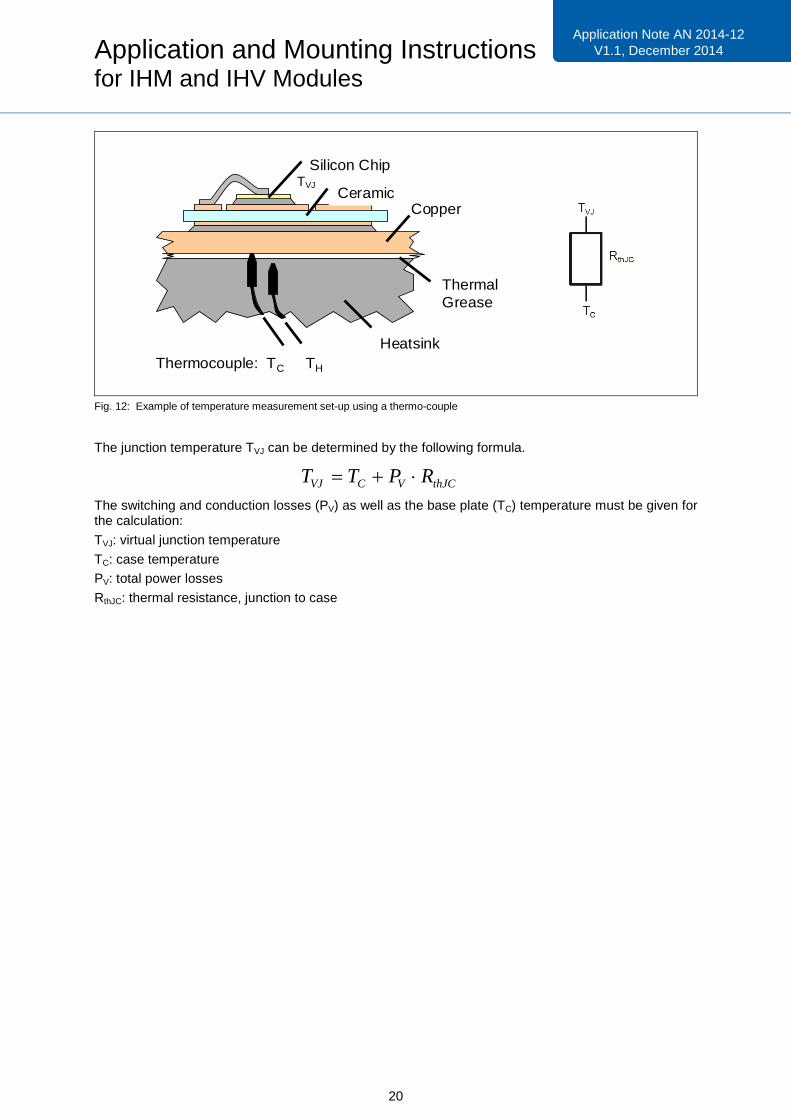
Fig. 12: Example of temperature measurement set-up using a thermo-couple
The junction temperature TVJ can be determined by the following formula.
The switching and conduction losses (PV) as well as the base plate (TC) temperature must be given forthe calculation:
TVJ: virtual junction temperature
TC: case temperature
PV: total power losses
RthJC: thermal resistance, junction to case
Ceramic
Thermocouple: TC TH
Silicon Chip
Copper
Heatsink
ThermalGrease
thJCVCVJ RPTT
TVJ

Application and Mounting Instructionsfor IHM and IHV Modules
21
Application Note AN2010-03V1.0, November2009
Application Note AN 2014-12V1.1, December 2014
8.4 Connection of the power and auxiliary terminals
The module must be connected within the permissible module tolerances specified in the outlinedrawings in the respective data sheets. The position and tolerance of adjacent components such asPCBs, DC-bus, mounting bolts or cables has to be designed such that, after the connection, nosustained effect on the static and / or dynamic tensile forces are exerted on the terminals.
To connect the power terminals of IHM / IHV modules M8 bolts are required. The bolts should beselected according to ISO4762, DIN7984 or DIN7985 with at least property class 8.8, in combinationwith a suitable washer and lock washer or combination screws according to DIN6900. The threadshould be clean and not lubricated. The screws are to be tightened with a torque specified in thedatasheet. Recommended is the use of a torque value near the maximum torque. The maximumtorque values in Table 7 must not be exceeded, however.
The tightening torque must be chosen so that the applied pre-tension force leads to a pure frictionalbond of the components. Knowledge of the friction coefficient μ is a prerequisite to accurately determine preload and tightening torque. The friction depends on many different factors, such asmaterial combination, surface, lubrication, temperature, etc. The torque values specified in Table 6assume a clean pair with a galvanised metric M6 steel bolt. Should the coefficient of friction in theconstruction differ from this, adjust the torque value accordingly.
Terminal Bolt Max. torque
Power M8 8 - 10 Nm
Auxiliary M4 2 Nm +5%,-10%
Table 7: Tightening torque M for the mounting bolts of the electrical connections
The choice of bolt length depends on the maximum thread depth specified for the module and thegauge of the connecting parts. The sum of these values must not be smaller than the selected boltthread length. The effective thread length of the bolts into the module power terminals must notexceed the maximum specified depth of 16mm. For auxiliary terminals this is 8mm. Other materialcombinations of bolts and / or the DC busbar material may require an adjustment of the mechanicalparameters and an evaluation of the corrosion stability in combination.
The design of the threaded connection for the power terminals must be such that the sum of all loadsoccurring does not exceed the yield point of the joined parts. Settling devices will increase theelasticity of the connection and thus compensate the settling effects. Thereby the pre-tension force willlargely be retained, and thus a loosening of the assembly is counteracted.
The connecting parts must be mounted onto the electrical contacts in a manner that the specifiedmaximum permissible forces are not exceeded during the assembly process.

Application and Mounting Instructionsfor IHM and IHV Modules
22
Application Note AN2010-03V1.0, November2009
Application Note AN 2014-12V1.1, December 2014
Fig. 13: Maximum permissible forces during the assembly process at the terminals of a IHM / IHV module
It is recommended to have an assembly which leaves the power and auxiliary terminals permanentlyfree of mechanical stress. Since such an assembly is inherently problematic over the entiretemperature range, the construction should be such that the power terminals of all package variantsas well as the auxiliary terminals exhibit a load bias by means of suitable spacers.
It must be ensured that the direction of the bias force always acts in the direction of the base plate.The suitability of the support must be evaluated individually in the structure.
Static forces in other directions as well as exposure to vibration and / or thermal expansion should beavoided.
The auxiliary terminals have to be connected accordingly, observing the common ESD guidelines. Noload current is permitted to flow through the auxiliary collector.
Fz < 200N
F+z < 50N
Fx < +/-20N
Fy < +/-20N
F-z < 250N
F+z < 100N (IHM B)
< 50N (IHM A)
Fx < +/-100N
Fy < +/-100N

Application and Mounting Instructionsfor IHM and IHV Modules
23
Application Note AN2010-03V1.0, November2009
Application Note AN 2014-12V1.1, December 2014
Fig. 14: Example for busbar support
The DC busbars have to be designed such that the maximum temperature at the power terminalsTTerminal =125°C will not be exceeded.
To design the power busbars it is necessary to consider not only the current rating but also theadditional power loss of the module’s terminal connections.

Application and Mounting Instructionsfor IHM and IHV Modules
24
Application Note AN2010-03V1.0, November2009
Application Note AN 2014-12V1.1, December 2014
8.5 Example of a low inductive, symmetrical phase-leg design
In addition to the maximum temperature at the terminals it is mandatory to assure compliance with themaximum collector-emitter voltage (VCE) at the power terminals and, hence, at the IGBT chipcorresponding to the respective RBSOA diagram given in the module data sheet.
It is recommended to connect the DC side via a laminated DC bus bar in order to minimize thesystemic switching overvoltage by reducing the leakage inductance as far as possible.
For a low-inductance structure and a symmetric current distribution in the DC-bus circuit a balancedconnection design of all modules is recommended [7]. The upper design in Fig. 15 gives a desiredsymmetric set up of the phase leg, where the current loops for all three subsystems are symmetric inrelation to their DC-capacitor, to the other leg and to the phase output.The lower design represents an asymmetric arrangement where the modules are oriented with theirlong side along the direction of the busbar. Di/dt during switching will result in different voltage dropsalong the emitter and collector chain as well as along the auxiliary emitters. As a result the gate-emitter voltages are different for each of the three subsystems, leading to different turn-on speed,current peaks current mis-sharing within the module.
Fig. 15: Example of phase-leg arrangements with two IHM / IHV modulesTop: symmetric set up of the phase legBottom: asymmetric arrangement; modules oriented with long side along the bus
DC link Capacitor Top Module Bottom Module
Phase Output
+-
Phase Output
+-
DC link Capacitor Top Module Bottom Module

Application and Mounting Instructionsfor IHM and IHV Modules
25
Application Note AN2010-03V1.0, November2009
Application Note AN 2014-12V1.1, December 2014
9. References
[1] TR14 Storage of Products supplied by Infineon Technologies
[2] AN2011-05 Industrial IGBT Modules - Explanation of Technical Information
[3] AN2010-02 Use of Power Cycling Curves for IGBT4
[4] AN2008-01 Definition and use of junction temperature values
[5] AN2006-02 Application of silk screen print templates
[6] Infineon Technologies IGBT Modules -Technologies, Driver and Applications; A. Volke,
M. Hornkamp, ISBN 978-3-00-032076-7
[7] Power Circuit design for clean switching; R. Bayerer, D. Domes, CIPS 2010