
Physiology -I PHL 215 PHL 215 Dr/ Gamal Gabr Pharmacy College Pharmacy College 1.

STATE OF CALIFORNIA
DEPARTMENT OF TRANSPORTATION __________________________________________________________
APPLICABLE STANDARDS
BOOK 3
I-15/I-215 Interchange Improvements (Devore)
FOR DESIGN AND CONSTRUCTION ON STATE HIGHWAY
On I-15 from 0.8 mile south of Glen Helen Parkway UC to 1.4 mile north of Kenwood Ave UC.
And
On I-215 from 1.2 mile south of Devore Road OC to the I-15 junction
DISTRICT 08, ROUTE I-15/I-215
__________________________________________________________
CONTRACT NO. 08-0K7104
08-SBD-I-15 PM 14.0/R16.4, I-215 PM 16.0/17.8
Project ID 08000003664
Federal Aid Project
Xxxxxxxx
Dated: April 17, 2012

Department of Transportation Book 3 – I-15/I-215 Interchange Improvements (Devore) Project E.A. 08-0K7104 Project ID 08000003664
Table of Contents i
TABLE OF CONTENTS 1 INDEX OF STANDARDS, MANUALS, GUIDELINES AND REFERENCES ...................................1-1
2 MODIFICATIONS TO DEPARTMENT (CALTRANS) MANUALS ..................................................2-1
3 MODIFICATIONS TO TECHNICAL MEMORANDA (NOT USED) ................................................3-1
4 DESIGN-BUILD MODIFICATIONS TO THE CALTRANS STANDARD SPECIFICATIONS 2010 EDITION ............................................................................................................................................4-1
5 MODIFICATIONS TO SPECIAL PROVISIONS ..................................................................................5-1
Department of Transportation Book 3 – I-15/I-215 Interchange Improvements (Devore) Project E.A. 08-0K7104 Project ID 08000003664
Index of Standards, Manuals, Guidelines and References 1-2
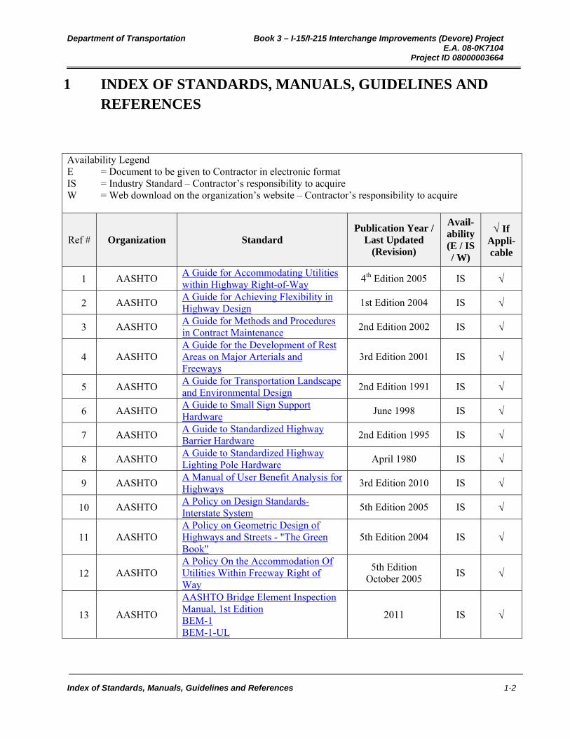
1 INDEX OF STANDARDS, MANUALS, GUIDELINES AND REFERENCES
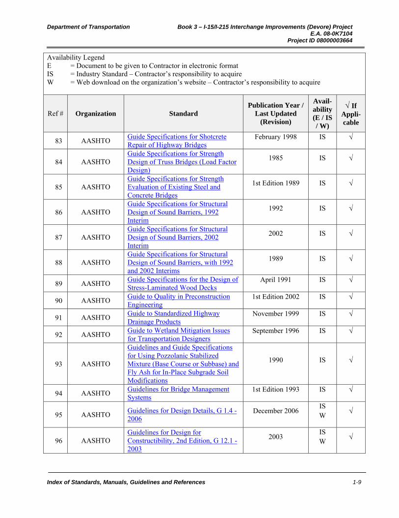
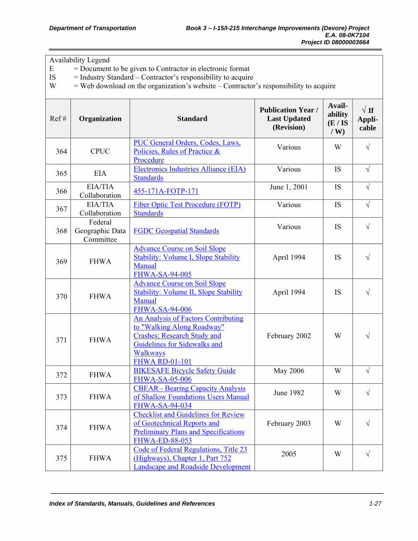
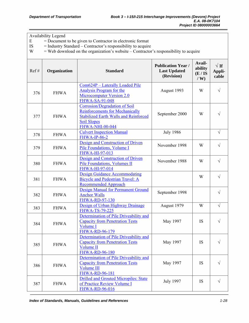
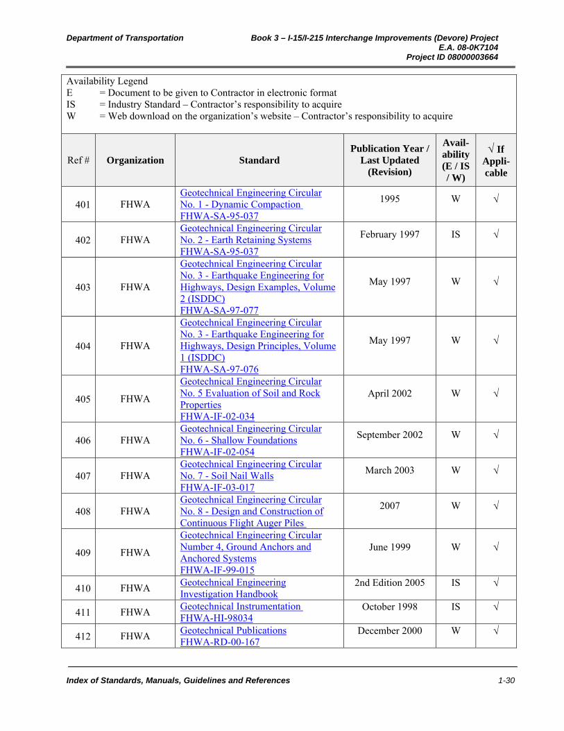
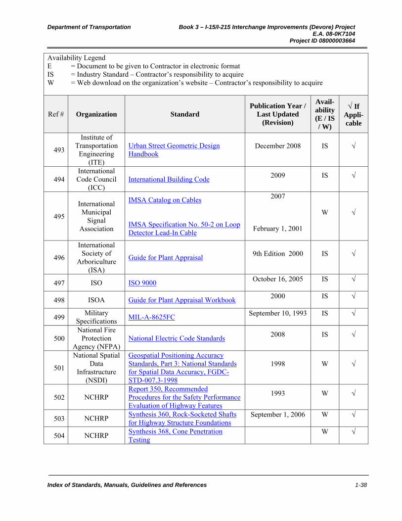
Availability Legend E = Document to be given to Contractor in electronic format IS = Industry Standard – Contractor’s responsibility to acquire W = Web download on the organization’s website – Contractor’s responsibility to acquire
Ref # Organization Standard Publication Year /
Last Updated (Revision)
Avail-ability (E / IS / W)
If Appli-cable
1 AASHTO A Guide for Accommodating Utilities within Highway Right-of-Way
4th Edition 2005 IS
2 AASHTO A Guide for Achieving Flexibility in Highway Design
1st Edition 2004 IS
3 AASHTO A Guide for Methods and Procedures in Contract Maintenance
2nd Edition 2002 IS
4 AASHTO A Guide for the Development of Rest Areas on Major Arterials and Freeways
3rd Edition 2001 IS
5 AASHTO A Guide for Transportation Landscape and Environmental Design
2nd Edition 1991 IS
6 AASHTO A Guide to Small Sign Support Hardware
June 1998 IS
7 AASHTO A Guide to Standardized Highway Barrier Hardware
2nd Edition 1995 IS
8 AASHTO A Guide to Standardized Highway Lighting Pole Hardware
April 1980 IS
9 AASHTO A Manual of User Benefit Analysis for Highways
3rd Edition 2010 IS
10 AASHTO A Policy on Design Standards-Interstate System
5th Edition 2005 IS
11 AASHTO A Policy on Geometric Design of Highways and Streets - "The Green Book"
5th Edition 2004 IS
12 AASHTO A Policy On the Accommodation Of Utilities Within Freeway Right of Way
5th Edition October 2005
IS
13 AASHTO
AASHTO Bridge Element Inspection Manual, 1st Edition BEM-1 BEM-1-UL
2011 IS

Department of Transportation Book 3 – I-15/I-215 Interchange Improvements (Devore) Project E.A. 08-0K7104 Project ID 08000003664
Index of Standards, Manuals, Guidelines and References 1-3
Availability Legend E = Document to be given to Contractor in electronic format IS = Industry Standard – Contractor’s responsibility to acquire W = Web download on the organization’s website – Contractor’s responsibility to acquire
Ref # Organization Standard Publication Year /
Last Updated (Revision)
Avail-ability (E / IS / W)
If Appli-cable
14 AASHTO AASHTO LRFD Bridge Construction Specifications, 3rd Edition, 2010 Interim Revisions
2010 IS
15 AASHTO
AASHTO LRFD Bridge Construction Specifications, 3rd Edition, with 2010 Interim Revisions LRFDCONS-3-M
3rd Edition 2010 IS
16 AASHTO
AASHTO LRFD Bridge Construction Specifications, 3rd Edition, with 2010 Interim Revisions, Single User Digital Publication LRFDCONS-3-UL
3rd Edition 2010 IS
17 AASHTO
AASHTO LRFD Bridge Design Specifications, Customary U.S. Units, 5th Edition, with 2010 Interim Revisions LRFDUS-5-M
5th Edition 2010 IS
18 AASHTO
AASHTO LRFD Bridge Design Specifications, Customary U.S. Units, 5th Edition, with 2010 Interim Revisions LRFDUS-5-UL
5th Edition 2010 IS
19 AASHTO AASHTO LRFD Bridge Design Specifications, Customary U.S. Units, 5th Edition, 2010 Interim Revisions
2010 IS
20 AASHTO
AASHTO LRFD Bridge Design Specifications, Customary U.S. Units, Second Edition, Single User Digital Publication LRFDUS-2-UL
2nd Edition 1998 IS
21 AASHTO AASHTO LRFD Bridge Design Specifications 4th Edition 2007 IS
22 AASHTO AASHTO LRFD Design Examples—Horizontally Curved Steel Bridges GHC-4I1-OL
2006 IS W
23 AASHTO
AASHTO LRFD Movable Highway Bridge Design Specifications, 2008 Interim Revisions LRFDMOV-2-I1
2008 IS

Department of Transportation Book 3 – I-15/I-215 Interchange Improvements (Devore) Project E.A. 08-0K7104 Project ID 08000003664
Index of Standards, Manuals, Guidelines and References 1-4
Availability Legend E = Document to be given to Contractor in electronic format IS = Industry Standard – Contractor’s responsibility to acquire W = Web download on the organization’s website – Contractor’s responsibility to acquire
Ref # Organization Standard Publication Year /
Last Updated (Revision)
Avail-ability (E / IS / W)
If Appli-cable
24 AASHTO
AASHTO LRFD Movable Highway Bridge Design Specifications, 2010 Interim Revisions LRFDMOV-2-I2-OL LRFDMOV-2-I2
2010 IS
25 AASHTO
AASHTO LRFD Movable Highway Bridge Design Specifications, 2011 Interim Revisions LRFDMOV-2-I3-OL LRFDMOV-2-I3
2011 IS
26 AASHTO
AASHTO LRFD Movable Highway Bridge Design Specifications, 2nd Edition, with 2008, 2010 and 2011 Interim Revisions LRFDMOV-2-M
2nd Edition 2007 IS
27 AASHTO
AASHTO/AWS D1.5M/D1.5:2010 Bridge Welding Code, 6th Edition, AASHTO 2011Interim Revisions BWC-6-I1 BWC-6-I1-OL
2011 IS
28 AASHTO
AASHTO/AWS D1.5M/D1.5:2010 Bridge Welding Code, 6th Edition, with 2011 AASHTO Interim Revisions BWC-6-M
6th Edition 2010
IS
29 AASHTO Above and Beyond January 2008 IS W
30 AASHTO An Informational Guide for a Training Program of Right-of-Way Personnel
2nd Edition 1975 IS
31 AASHTO Asset Management Data Collection Guide, AASHTO-AGC-ARTBA Task Force 45 Document
June 2006 IS
32 AASHTO Best Practices in Context-Sensitive Solutions, 2005 Competition
2005 IS
33 AASHTO Best Practices in Context-Sensitive Solutions, 2006 Competition
2006 IS
34 AASHTO Best Practices in Environmental Partnering: Raising the Bar
1998 IS

Department of Transportation Book 3 – I-15/I-215 Interchange Improvements (Devore) Project E.A. 08-0K7104 Project ID 08000003664
Index of Standards, Manuals, Guidelines and References 1-5
Availability Legend E = Document to be given to Contractor in electronic format IS = Industry Standard – Contractor’s responsibility to acquire W = Web download on the organization’s website – Contractor’s responsibility to acquire
Ref # Organization Standard Publication Year /
Last Updated (Revision)
Avail-ability (E / IS / W)
If Appli-cable
35 AASHTO
Construction Handbook for Bridge Temporary Works, 1st Edition, 2008 Interim Revisions CHBTW-1-I1
2008 IS
36 AASHTO
Construction Handbook for Bridge Temporary Works, 1st Edition, with 2008 Interim Revisions CHBTW-1-M
1st Edition 1995 IS
37 AASHTO Construction Manual for Highway Construction
4th Edition 1990 IS
38 AASHTO Design Drawing Presentation Guidelines, G 1.2 - 2003
2003 IS W
39 AASHTO Design Policy Archive, 1st Edition, Single-User CD-ROM
January 2004 IS
40 AASHTO Driving to Success with CSS 2007 IS
41 AASHTO EMS Implementation Handy Guide Number One: Making the Case for an Environmental Management System
May 2004 IS
42 AASHTO
EMS Implementation Handy Guide Number Two: EMS, A Bridge for Organizational Coordination and Communications
May 2004 IS
43 AASHTO Environmental Successes in Transportation Project Development
2001 IS
44 AASHTO Foundation Investigation Manual 2nd Edition 1978 IS
45 AASHTO Guidance on Sharing Freeway and Highway Rights-of-Way for Telecommunications
1997 IS
46 AASHTO Guide Design Specifications for Bridge Temporary Works, 1st Edition, with 2008 Interim Revisions
1st Edition 1995 IS
47 AASHTO
Guide Design Specifications for Bridge Temporary Works, 1st Edition, with 2008 Interim Revisions GSBTW-1-M
1995 IS
Department of Transportation Book 3 – I-15/I-215 Interchange Improvements (Devore) Project E.A. 08-0K7104 Project ID 08000003664
Index of Standards, Manuals, Guidelines and References 1-6
Availability Legend E = Document to be given to Contractor in electronic format IS = Industry Standard – Contractor’s responsibility to acquire W = Web download on the organization’s website – Contractor’s responsibility to acquire
Ref # Organization Standard Publication Year /
Last Updated (Revision)
Avail-ability (E / IS / W)
If Appli-cable
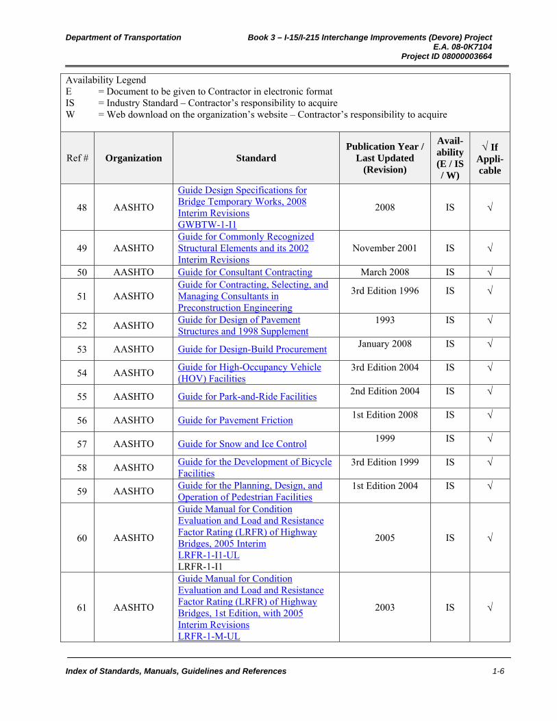
48 AASHTO
Guide Design Specifications for Bridge Temporary Works, 2008 Interim Revisions GWBTW-1-I1
2008 IS
49 AASHTO Guide for Commonly Recognized Structural Elements and its 2002 Interim Revisions
November 2001 IS
50 AASHTO Guide for Consultant Contracting March 2008 IS
51 AASHTO Guide for Contracting, Selecting, and Managing Consultants in Preconstruction Engineering
3rd Edition 1996 IS
52 AASHTO Guide for Design of Pavement Structures and 1998 Supplement
1993 IS
53 AASHTO Guide for Design-Build Procurement January 2008 IS
54 AASHTO Guide for High-Occupancy Vehicle (HOV) Facilities
3rd Edition 2004 IS
55 AASHTO Guide for Park-and-Ride Facilities 2nd Edition 2004 IS
56 AASHTO Guide for Pavement Friction 1st Edition 2008 IS
57 AASHTO Guide for Snow and Ice Control 1999 IS
58 AASHTO Guide for the Development of Bicycle Facilities
3rd Edition 1999 IS
59 AASHTO Guide for the Planning, Design, and Operation of Pedestrian Facilities
1st Edition 2004 IS
60 AASHTO
Guide Manual for Condition Evaluation and Load and Resistance Factor Rating (LRFR) of Highway Bridges, 2005 Interim LRFR-1-I1-UL LRFR-1-I1
2005 IS
61 AASHTO
Guide Manual for Condition Evaluation and Load and Resistance Factor Rating (LRFR) of Highway Bridges, 1st Edition, with 2005 Interim Revisions LRFR-1-M-UL
2003 IS
Department of Transportation Book 3 – I-15/I-215 Interchange Improvements (Devore) Project E.A. 08-0K7104 Project ID 08000003664
Index of Standards, Manuals, Guidelines and References 1-7
Availability Legend E = Document to be given to Contractor in electronic format IS = Industry Standard – Contractor’s responsibility to acquire W = Web download on the organization’s website – Contractor’s responsibility to acquire
Ref # Organization Standard Publication Year /
Last Updated (Revision)
Avail-ability (E / IS / W)
If Appli-cable
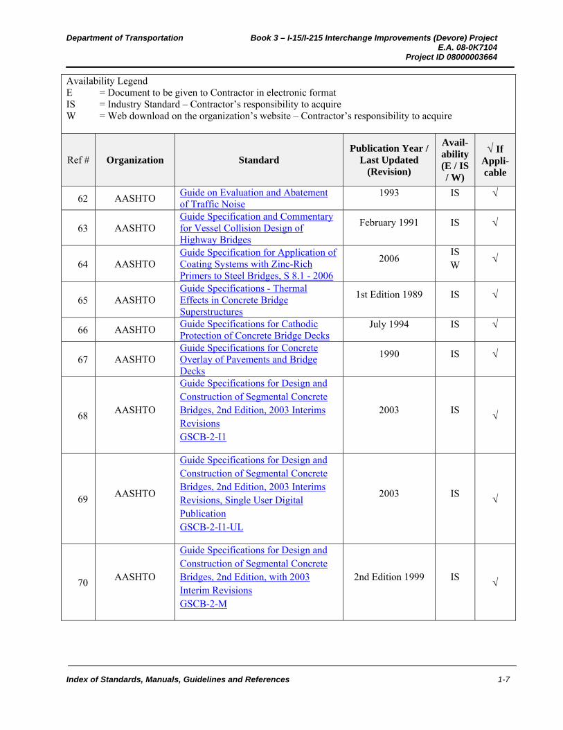
62 AASHTO Guide on Evaluation and Abatement of Traffic Noise
1993 IS
63 AASHTO Guide Specification and Commentary for Vessel Collision Design of Highway Bridges
February 1991 IS
64 AASHTO Guide Specification for Application of Coating Systems with Zinc-Rich Primers to Steel Bridges, S 8.1 - 2006
2006 IS W
65 AASHTO Guide Specifications - Thermal Effects in Concrete Bridge Superstructures
1st Edition 1989 IS
66 AASHTO Guide Specifications for Cathodic Protection of Concrete Bridge Decks
July 1994 IS
67 AASHTO Guide Specifications for Concrete Overlay of Pavements and Bridge Decks
1990 IS
68 AASHTO
Guide Specifications for Design and Construction of Segmental Concrete Bridges, 2nd Edition, 2003 Interims Revisions GSCB-2-I1
2003 IS
69 AASHTO
Guide Specifications for Design and Construction of Segmental Concrete Bridges, 2nd Edition, 2003 Interims Revisions, Single User Digital Publication GSCB-2-I1-UL
2003 IS
70 AASHTO
Guide Specifications for Design and Construction of Segmental Concrete Bridges, 2nd Edition, with 2003 Interim Revisions GSCB-2-M
2nd Edition 1999 IS
Department of Transportation Book 3 – I-15/I-215 Interchange Improvements (Devore) Project E.A. 08-0K7104 Project ID 08000003664
Index of Standards, Manuals, Guidelines and References 1-8
Availability Legend E = Document to be given to Contractor in electronic format IS = Industry Standard – Contractor’s responsibility to acquire W = Web download on the organization’s website – Contractor’s responsibility to acquire
Ref # Organization Standard Publication Year /
Last Updated (Revision)
Avail-ability (E / IS / W)
If Appli-cable
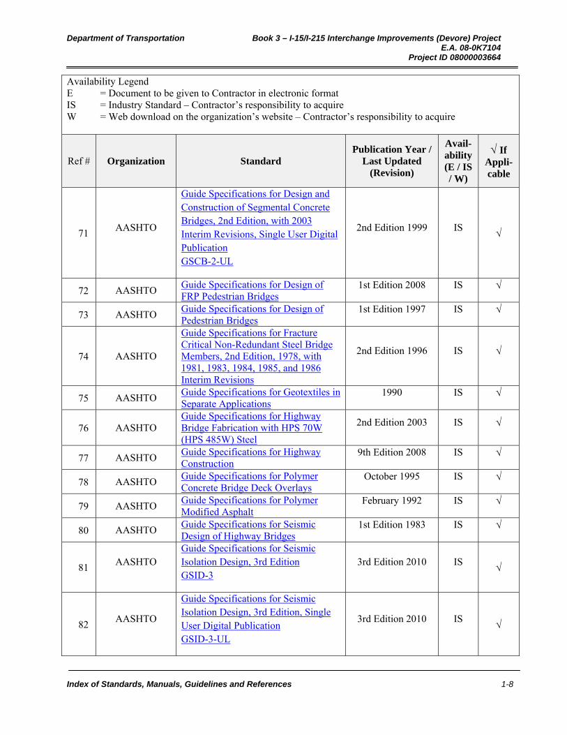
71 AASHTO
Guide Specifications for Design and Construction of Segmental Concrete Bridges, 2nd Edition, with 2003 Interim Revisions, Single User Digital Publication GSCB-2-UL
2nd Edition 1999 IS
72 AASHTO Guide Specifications for Design of FRP Pedestrian Bridges
1st Edition 2008 IS
73 AASHTO Guide Specifications for Design of Pedestrian Bridges
1st Edition 1997 IS
74 AASHTO
Guide Specifications for Fracture Critical Non-Redundant Steel Bridge Members, 2nd Edition, 1978, with 1981, 1983, 1984, 1985, and 1986 Interim Revisions
2nd Edition 1996 IS
75 AASHTO Guide Specifications for Geotextiles in Separate Applications
1990 IS
76 AASHTO Guide Specifications for Highway Bridge Fabrication with HPS 70W (HPS 485W) Steel
2nd Edition 2003 IS
77 AASHTO Guide Specifications for Highway Construction
9th Edition 2008 IS
78 AASHTO Guide Specifications for Polymer Concrete Bridge Deck Overlays
October 1995 IS
79 AASHTO Guide Specifications for Polymer Modified Asphalt
February 1992 IS
80 AASHTO Guide Specifications for Seismic Design of Highway Bridges
1st Edition 1983 IS
81 AASHTO
Guide Specifications for Seismic Isolation Design, 3rd Edition GSID-3
3rd Edition 2010 IS
82 AASHTO
Guide Specifications for Seismic Isolation Design, 3rd Edition, Single User Digital Publication GSID-3-UL
3rd Edition 2010 IS
Department of Transportation Book 3 – I-15/I-215 Interchange Improvements (Devore) Project E.A. 08-0K7104 Project ID 08000003664
Index of Standards, Manuals, Guidelines and References 1-9
Availability Legend E = Document to be given to Contractor in electronic format IS = Industry Standard – Contractor’s responsibility to acquire W = Web download on the organization’s website – Contractor’s responsibility to acquire
Ref # Organization Standard Publication Year /
Last Updated (Revision)
Avail-ability (E / IS / W)
If Appli-cable
83 AASHTO Guide Specifications for Shotcrete Repair of Highway Bridges
February 1998 IS
84 AASHTO Guide Specifications for Strength Design of Truss Bridges (Load Factor Design)
1985 IS
85 AASHTO Guide Specifications for Strength Evaluation of Existing Steel and Concrete Bridges
1st Edition 1989 IS
86 AASHTO Guide Specifications for Structural Design of Sound Barriers, 1992 Interim
1992 IS
87 AASHTO Guide Specifications for Structural Design of Sound Barriers, 2002 Interim
2002 IS
88 AASHTO Guide Specifications for Structural Design of Sound Barriers, with 1992 and 2002 Interims
1989 IS
89 AASHTO Guide Specifications for the Design of Stress-Laminated Wood Decks
April 1991 IS
90 AASHTO Guide to Quality in Preconstruction Engineering
1st Edition 2002 IS
91 AASHTO Guide to Standardized Highway Drainage Products
November 1999 IS
92 AASHTO Guide to Wetland Mitigation Issues for Transportation Designers
September 1996 IS
93 AASHTO
Guidelines and Guide Specifications for Using Pozzolanic Stabilized Mixture (Base Course or Subbase) and Fly Ash for In-Place Subgrade Soil Modifications
1990 IS
94 AASHTO Guidelines for Bridge Management Systems
1st Edition 1993 IS
95 AASHTO Guidelines for Design Details, G 1.4 - 2006
December 2006 IS W
96 AASHTO Guidelines for Design for Constructibility, 2nd Edition, G 12.1 - 2003
2003 IS W

Department of Transportation Book 3 – I-15/I-215 Interchange Improvements (Devore) Project E.A. 08-0K7104 Project ID 08000003664
Index of Standards, Manuals, Guidelines and References 1-10
Availability Legend E = Document to be given to Contractor in electronic format IS = Industry Standard – Contractor’s responsibility to acquire W = Web download on the organization’s website – Contractor’s responsibility to acquire
Ref # Organization Standard Publication Year /
Last Updated (Revision)
Avail-ability (E / IS / W)
If Appli-cable
97 AASHTO Guidelines for Geometric Design of Very Low-Volume Local Roads (ADT ≤ 400)
1st Edition 2001 IS
98 AASHTO Guidelines for Historic Bridge Rehabilitation and Replacement
1st Edition 2008 IS
99 AASHTO Guidelines for Maintenance Management Systems
1st Edition 2004 IS
100 AASHTO Guidelines for the Selection of Supplemental Guide Signs for Traffic Generators Adjacent to Freeways
4th Edition 2001 IS
101 AASHTO Guidelines for Value Engineering 3rd Edition 2010 IS
102 AASHTO Hazardous Waste Guide for Project Development
1st Edition 1990 IS
103 AASHTO Highway Drainage Guidelines 4th Edition 2007 IS
104 AASHTO Highway Safety Design and Operations Guide
3rd Edition 1997 IS
105 AASHTO Hot-Mix Asphalt Paving Handbook 2nd Edition 2000 IS
106 AASHTO Implementation Manual for Quality Assurance
February 1996 IS
107 AASHTO Improving the Quality of Environmental Documents
May 2006 IS
108 AASHTO In Situ Soil Improvement Techniques 1st Edition 1990 IS
109 AASHTO Informational Guide on Fencing Controlled Access Highways
3rd Edition 1990 IS
110 AASHTO Inspectors' Guide for Shotcrete Repair of Bridges
December 1999 IS
111 AASHTO Maintenance Manual for Roadways and Bridges
4th Edition 2007 IS
112 AASHTO Manual for Bridge Evaluation 2nd Edition 2011 IS
113 AASHTO Manual for Condition Evaluation of Bridges, 2nd Edition with 2001 and 2003 Interim Revisions
2nd Edition 2000 IS
114 AASHTO Manual for Corrosion Protection of Concrete Components in Bridges
1992 IS

Department of Transportation Book 3 – I-15/I-215 Interchange Improvements (Devore) Project E.A. 08-0K7104 Project ID 08000003664
Index of Standards, Manuals, Guidelines and References 1-11
Availability Legend E = Document to be given to Contractor in electronic format IS = Industry Standard – Contractor’s responsibility to acquire W = Web download on the organization’s website – Contractor’s responsibility to acquire
Ref # Organization Standard Publication Year /
Last Updated (Revision)
Avail-ability (E / IS / W)
If Appli-cable
115 AASHTO Manual on Subsurface Investigations 1st Edition 1988 IS
116 AASHTO Manual on Uniform Traffic Control Devices
2009 Edtion IS W
117 AASHTO Mechanistic-Empirical Pavement Design Guide, Interim Edition: A Manual of Practice
2008 IS
118 AASHTO Model Drainage Manual, CD-ROM 3rd Edition 2005 IS
119 AASHTO Movable Bridge Inspection, Evaluation, and Maintenance Manual
1st Edition 1998 IS
120 AASHTO National Transportation Communications for ITS Protocol (NTCIP)
IS
121 AASHTO National Transportation Product Evaluation Program (NTPEP)
IS
122 AASHTO Partnering Handbook 2005 IS
123 AASHTO Pavement Deflection Data Exchange: Technical Data Guide
1998 IS
124 AASHTO Pavement Management Guide 1st Edition 2001 IS
125 AASHTO Policy on Land Use and Source Control Aspects of Traffic Noise Attenuation
1980 IS
126 AASHTO
Practitioner's Handbook #1: Maintaining a Project File and Preparing an Administrative Record for a NEPA Study
2006 IS W
127 AASHTO Practitioner's Handbook #10: Using the Transportation Planning Process to Support the NEPA Process
2008 IS W
128 AASHTO Practitioner's Handbook #2: Responding to Comments on an Environmental Impact Statement
2006 IS W
129 AASHTO Practitioner's Handbook #3: Managing the NEPA Process for Toll Lanes and Toll Roads
2006 IS W
Department of Transportation Book 3 – I-15/I-215 Interchange Improvements (Devore) Project E.A. 08-0K7104 Project ID 08000003664
Index of Standards, Manuals, Guidelines and References 1-12
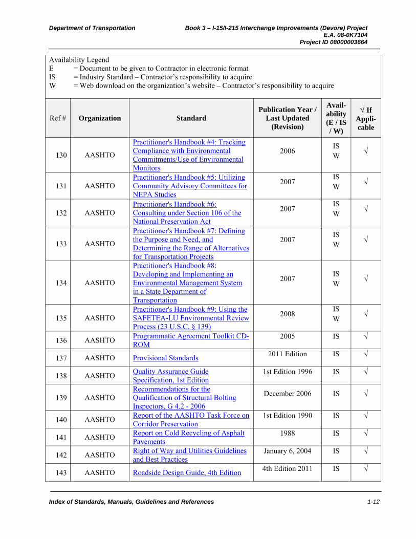
Availability Legend E = Document to be given to Contractor in electronic format IS = Industry Standard – Contractor’s responsibility to acquire W = Web download on the organization’s website – Contractor’s responsibility to acquire
Ref # Organization Standard Publication Year /
Last Updated (Revision)
Avail-ability (E / IS / W)
If Appli-cable
130 AASHTO
Practitioner's Handbook #4: Tracking Compliance with Environmental Commitments/Use of Environmental Monitors
2006 IS W
131 AASHTO Practitioner's Handbook #5: Utilizing Community Advisory Committees for NEPA Studies
2007 IS W
132 AASHTO Practitioner's Handbook #6: Consulting under Section 106 of the National Preservation Act
2007 IS W
133 AASHTO
Practitioner's Handbook #7: Defining the Purpose and Need, and Determining the Range of Alternatives for Transportation Projects
2007 IS W
134 AASHTO
Practitioner's Handbook #8: Developing and Implementing an Environmental Management System in a State Department of Transportation
2007 IS W
135 AASHTO Practitioner's Handbook #9: Using the SAFETEA-LU Environmental Review Process (23 U.S.C. § 139)
2008 IS W
136 AASHTO Programmatic Agreement Toolkit CD-ROM
2005 IS
137 AASHTO Provisional Standards 2011 Edition IS
138 AASHTO Quality Assurance Guide Specification, 1st Edition
1st Edition 1996 IS
139 AASHTO Recommendations for the Qualification of Structural Bolting Inspectors, G 4.2 - 2006
December 2006 IS
140 AASHTO Report of the AASHTO Task Force on Corridor Preservation
1st Edition 1990 IS
141 AASHTO Report on Cold Recycling of Asphalt Pavements
1988 IS
142 AASHTO Right of Way and Utilities Guidelines and Best Practices
January 6, 2004 IS
143 AASHTO Roadside Design Guide, 4th Edition 4th Edition 2011 IS

Department of Transportation Book 3 – I-15/I-215 Interchange Improvements (Devore) Project E.A. 08-0K7104 Project ID 08000003664
Index of Standards, Manuals, Guidelines and References 1-13
Availability Legend E = Document to be given to Contractor in electronic format IS = Industry Standard – Contractor’s responsibility to acquire W = Web download on the organization’s website – Contractor’s responsibility to acquire
Ref # Organization Standard Publication Year /
Last Updated (Revision)
Avail-ability (E / IS / W)
If Appli-cable
144 AASHTO Roadway Lighting Design Guide October 2005 IS
145 AASHTO Sample Owners Quality Assurance Manual, G 4.4 - 2006
2006 IS W
146 AASHTO SDMS™ Data Structure Technical Guide
2000 IS
147 AASHTO Segregation—Causes and Cures for Hot-Mix Asphalt
1st Edition 1997 IS
148 AASHTO Shop Detail Drawing Review/Approval Guidelines, G 1.1-2000
2000 IS W
149 AASHTO Shop Detail Drawings Presentation Guidelines, G 1.3-2002
2002 IS W
150 AASHTO Standard Specifications for Highway Bridges
13th Edition 1983 IS
151 AASHTO Standard Specifications for Highway Bridges
17th Edition 2002 IS
152 AASHTO Standard Specifications for Highway Bridges
2nd Edition 1935 IS
153 AASHTO Standard Specifications for Highway Bridges
8th Edition 1961 IS
154 AASHTO Standard Specifications for Highway Bridges and Incidental Structures
1st Edition 1931 IS
155 AASHTO Standard Specifications for Movable Highway Bridges, with 1992, 1993, and 1995 Interims
August 1988 IS
156 AASHTO
Standard Specifications for Structural Supports for Highway Signs, Luminaires and Traffic Signals, 5th Edition, 2010 Interim Revisions LTS-5-I1 LTS-5-I1-UL
2010 IS

Department of Transportation Book 3 – I-15/I-215 Interchange Improvements (Devore) Project E.A. 08-0K7104 Project ID 08000003664
Index of Standards, Manuals, Guidelines and References 1-14
Availability Legend E = Document to be given to Contractor in electronic format IS = Industry Standard – Contractor’s responsibility to acquire W = Web download on the organization’s website – Contractor’s responsibility to acquire
Ref # Organization Standard Publication Year /
Last Updated (Revision)
Avail-ability (E / IS / W)
If Appli-cable
157 AASHTO
Standard Specifications for Structural Supports for Highway Signs, Luminaires and Traffic Signals, 5th Edition, 2011 Interim Revisions LTS-5-I2 LTS-5-I2-UL
2011 IS
158 AASHTO
Standard Specifications for Structural Supports for Highway Signs, Luminaires and Traffic Signals, 5th Edition, with 2010 and 2011 Interim Revisions LTS-5-M
5th Edition 2009 IS
159 AASHTO
Standard Specifications for Transportation Materials and Methods of Sampling and Testing, 31st Edition, and Provisional Standards, 2011 Edition with single-user CD-ROM
31st Edition 2011 IS
160 AASHTO Steel Bridge Bearing Design and Detailing Guidelines, G9.1-2004
2004 IS
161 AASHTO Steel Bridge Erection Guide Specification, Sample Erection Plans, S10.1-2007
2007 IS
162 AASHTO Steel Bridge Fabrication Guide Specification, S 2.1-2002
2002 IS
163 AASHTO Steel Bridge Fabrication QC/QA Guide Specification, S 4.1-2002
2002 IS
164 AASHTO
Strategic Highway Safety Plan - A Comprehensive Plan to Substantially Reduce Vehicle-Related Fatalities and Injuries on the Nation's Highways
2005 IS
165 AASHTO
Taking the High Road: The Environmental and Social Contributions of America's Highway Programs
1st Edition 2001 IS
166 AASHTO The Use and State-of-the-Practice of Fiber Reinforced Concrete
2001 IS

Department of Transportation Book 3 – I-15/I-215 Interchange Improvements (Devore) Project E.A. 08-0K7104 Project ID 08000003664
Index of Standards, Manuals, Guidelines and References 1-15
Availability Legend E = Document to be given to Contractor in electronic format IS = Industry Standard – Contractor’s responsibility to acquire W = Web download on the organization’s website – Contractor’s responsibility to acquire
Ref # Organization Standard Publication Year /
Last Updated (Revision)
Avail-ability (E / IS / W)
If Appli-cable
167 AASHTO Uniform Vehicle Code—Millenium Edition
Millenium Edition IS
168 AASHTO
Using the Environmental Management System to Meet Transportation Challenges and Opportunities. An Implementation Guide
2003 IS
169 AASHTO Virtual Superpave Laboratory Interactive CD-ROM
2005 IS
170 ACI
ACI-318-08 Building Code Requirements for Structural Concrete and Commentary (Includes Errata)
January 1, 2008 IS
171 ADAAG American with Disabilities Act Accessibility Guidelines for Buildings and Facilities
September 2002 W
172 Aluminum
Association for Alloy
Aluminum Books and Alloys Number 319.0
Various IS
173
American Congress on
Surveying and Mapping and the
American Society of Civil
Engineers
Definitions of Surveying and Associated Terms
1978 IS
174 American Iron
and Steel Institute
Handbook of Steel Drainage and Highway Construction Products
2007 W
175 ANSI Illuminating Engineering Society of North America Roadway Lighting ANSI Approved
July 1, 2000 IS
176 ANSI Standard for Welding Procedure and Performance Qualification
November 4, 2004 IS
177 API
Recommended Practice for Planning, Design, and Constructing Fixed Offshore Platforms – Load and Resistance Factor Design
July 1, 1993 IS
178 APWA American Public Works Association Standard Location for Utilities in Public Right of Ways
February 29, 2000 W
Department of Transportation Book 3 – I-15/I-215 Interchange Improvements (Devore) Project E.A. 08-0K7104 Project ID 08000003664
Index of Standards, Manuals, Guidelines and References 1-16
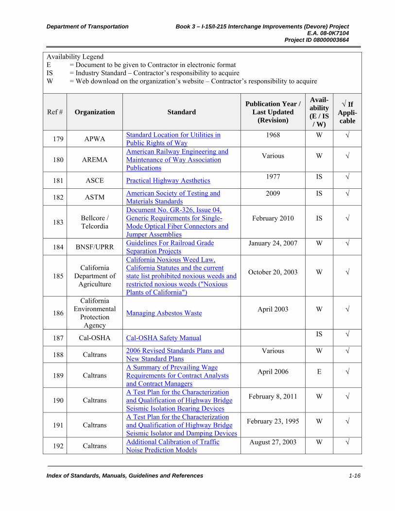
Availability Legend E = Document to be given to Contractor in electronic format IS = Industry Standard – Contractor’s responsibility to acquire W = Web download on the organization’s website – Contractor’s responsibility to acquire
Ref # Organization Standard Publication Year /
Last Updated (Revision)
Avail-ability (E / IS / W)
If Appli-cable
179 APWA Standard Location for Utilities in Public Rights of Way
1968 W
180 AREMA American Railway Engineering and Maintenance of Way Association Publications
Various W
181 ASCE Practical Highway Aesthetics 1977 IS
182 ASTM American Society of Testing and Materials Standards
2009 IS
183 Bellcore / Telcordia
Document No. GR-326, Issue 04, Generic Requirements for Single-Mode Optical Fiber Connectors and Jumper Assemblies
February 2010 IS
184 BNSF/UPRR Guidelines For Railroad Grade Separation Projects
January 24, 2007 W
185 California
Department of Agriculture
California Noxious Weed Law, California Statutes and the current state list prohibited noxious weeds and restricted noxious weeds ("Noxious Plants of California")
October 20, 2003 W
186
California Environmental
Protection Agency
Managing Asbestos Waste April 2003 W
187 Cal-OSHA Cal-OSHA Safety Manual IS
188 Caltrans 2006 Revised Standards Plans and New Standard Plans
Various W
189 Caltrans A Summary of Prevailing Wage Requirements for Contract Analysts and Contract Managers
April 2006 E
190 Caltrans A Test Plan for the Characterization and Qualification of Highway Bridge Seismic Isolation Bearing Devices
February 8, 2011 W
191 Caltrans A Test Plan for the Characterization and Qualification of Highway Bridge Seismic Isolator and Damping Devices
February 23, 1995 W
192 Caltrans Additional Calibration of Traffic Noise Prediction Models
August 27, 2003 W
Department of Transportation Book 3 – I-15/I-215 Interchange Improvements (Devore) Project E.A. 08-0K7104 Project ID 08000003664
Index of Standards, Manuals, Guidelines and References 1-17
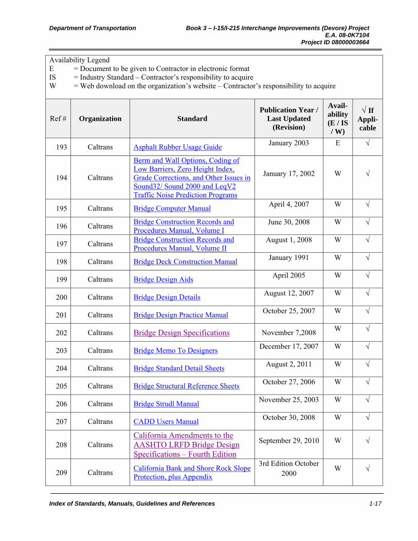
Availability Legend E = Document to be given to Contractor in electronic format IS = Industry Standard – Contractor’s responsibility to acquire W = Web download on the organization’s website – Contractor’s responsibility to acquire
Ref # Organization Standard Publication Year /
Last Updated (Revision)
Avail-ability (E / IS / W)
If Appli-cable
193 Caltrans Asphalt Rubber Usage Guide January 2003 E
194 Caltrans
Berm and Wall Options, Coding of Low Barriers, Zero Height Index, Grade Corrections, and Other Issues in Sound32/ Sound 2000 and LeqV2 Traffic Noise Prediction Programs
January 17, 2002 W
195 Caltrans Bridge Computer Manual April 4, 2007 W
196 Caltrans Bridge Construction Records and Procedures Manual, Volume I
June 30, 2008 W
197 Caltrans Bridge Construction Records and Procedures Manual, Volume II
August 1, 2008 W
198 Caltrans Bridge Deck Construction Manual January 1991 W
199 Caltrans Bridge Design Aids April 2005 W
200 Caltrans Bridge Design Details August 12, 2007 W
201 Caltrans Bridge Design Practice Manual October 25, 2007 W
202 Caltrans Bridge Design Specifications November 7,2008 W
203 Caltrans Bridge Memo To Designers December 17, 2007 W
204 Caltrans Bridge Standard Detail Sheets August 2, 2011 W
205 Caltrans Bridge Structural Reference Sheets October 27, 2006 W
206 Caltrans Bridge Strudl Manual November 25, 2003 W
207 Caltrans CADD Users Manual October 30, 2008 W
208 Caltrans California Amendments to the AASHTO LRFD Bridge Design Specifications – Fourth Edition
September 29, 2010 W
209 Caltrans California Bank and Shore Rock Slope Protection, plus Appendix
3rd Edition October 2000
W

Department of Transportation Book 3 – I-15/I-215 Interchange Improvements (Devore) Project E.A. 08-0K7104 Project ID 08000003664
Index of Standards, Manuals, Guidelines and References 1-18
Availability Legend E = Document to be given to Contractor in electronic format IS = Industry Standard – Contractor’s responsibility to acquire W = Web download on the organization’s website – Contractor’s responsibility to acquire
Ref # Organization Standard Publication Year /
Last Updated (Revision)
Avail-ability (E / IS / W)
If Appli-cable
210 Caltrans California Code Regulations Title 24 Portions W
211 Caltrans California Foundation Manual July 1997 E
212 Caltrans California Highway Barrier Aesthetics June 2002 E
213 Caltrans California Manual on Uniform Traffic Control Devices (CA MUTCD)
September 26, 2006 W
214 Caltrans California Seismic Hazard Map and Report
July 1996 W
215 Caltrans California Sign Chart September 2006 W
216 Caltrans California Sign Specifications September 28, 2006 W
217 Caltrans California Test Methods Various W
218 Caltrans California Vehicle Noise Emission Levels
January 1987 W
219 Caltrans Caltrans Strategic Plan 2007-2012 December 17, 2007 W
220 Caltrans Changeable Message Sign Guidelines April 2006 W
221 Caltrans CHP/Caltrans Call Box and Motorist Aid Guidelines
May 1999 E
222 Caltrans Code of Safe Practices for Geotechnical Drilling
October 27, 2005 W
223 Caltrans Code of Safe Surveying Practices 2002 E
224 Caltrans Confidentiality Agreement October 2003 W
225 Caltrans Construction Manual September 2007 W
226 Caltrans Construction Policy Bulletins Various W
227 Caltrans Construction Procedure Directives Various W
228 Caltrans Construction Site Best Management Practices (BMPs) Field Manual and Troubleshooting Guide
January 2003 W

Department of Transportation Book 3 – I-15/I-215 Interchange Improvements (Devore) Project E.A. 08-0K7104 Project ID 08000003664
Index of Standards, Manuals, Guidelines and References 1-19
Availability Legend E = Document to be given to Contractor in electronic format IS = Industry Standard – Contractor’s responsibility to acquire W = Web download on the organization’s website – Contractor’s responsibility to acquire
Ref # Organization Standard Publication Year /
Last Updated (Revision)
Avail-ability (E / IS / W)
If Appli-cable
229 Caltrans Construction Site Best Management Practices (BMPs) Manual
May 2004 W
230 Caltrans Construction Site BMPs Details and Drawings
Various W
231 Caltrans Construction Site BMPs Fact Sheets Various W
232 Caltrans Construction Site BMPs Symbols W
233 Caltrans Construction Site Storm Water Quality Sampling Guidance Manual
December 2003 W
234 Caltrans Construction Storm Water Coordinator Guidance Manual
January 2003 W
235 Caltrans Continuously Reinforced Concrete Pavement (CRCP) Design and Construction Guide
June 5, 2007 W
236 Caltrans Corrosion Guidelines September 2003 W
237 Caltrans Cost Effectiveness-Public Interest Finding Guidelines
November 2006 E
238 Caltrans Deputy Directives by Number Various E
239 Caltrans Design Information Bulletin Various E
240 Caltrans Design Memoranda Various E
241 Caltrans Director's Policies by Number Various E
242 Caltrans
Distance Limits for Traffic Noise Prediction Models Technical Advisory, Noise TAN-02-02
April 24, 2002 W
243 Caltrans Division of Construction Storm Water Management Enforcement Guidance Manual
December 2003 W
244 Caltrans Dowel Bar Retrofit - MTAG Vol. II - Rigid Pavement Preservation Chapter 6
2nd Edition January 18, 2008
W
245 Caltrans Drafting and Plans Manual of Instructions
March 1996 W
Department of Transportation Book 3 – I-15/I-215 Interchange Improvements (Devore) Project E.A. 08-0K7104 Project ID 08000003664
Index of Standards, Manuals, Guidelines and References 1-20
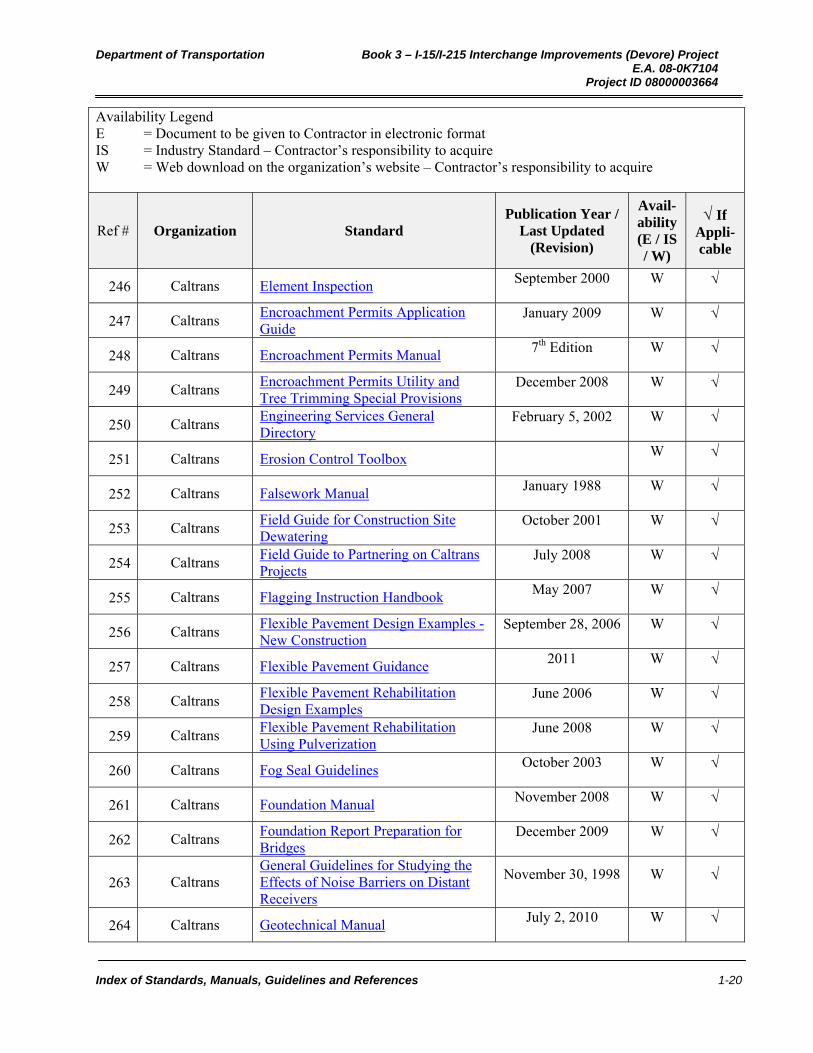
Availability Legend E = Document to be given to Contractor in electronic format IS = Industry Standard – Contractor’s responsibility to acquire W = Web download on the organization’s website – Contractor’s responsibility to acquire
Ref # Organization Standard Publication Year /
Last Updated (Revision)
Avail-ability (E / IS / W)
If Appli-cable
246 Caltrans Element Inspection September 2000 W
247 Caltrans Encroachment Permits Application Guide
January 2009 W
248 Caltrans Encroachment Permits Manual 7th Edition W
249 Caltrans Encroachment Permits Utility and Tree Trimming Special Provisions
December 2008 W
250 Caltrans Engineering Services General Directory
February 5, 2002 W
251 Caltrans Erosion Control Toolbox W
252 Caltrans Falsework Manual January 1988 W
253 Caltrans Field Guide for Construction Site Dewatering
October 2001 W
254 Caltrans Field Guide to Partnering on Caltrans Projects
July 2008 W
255 Caltrans Flagging Instruction Handbook May 2007 W
256 Caltrans Flexible Pavement Design Examples - New Construction
September 28, 2006 W
257 Caltrans Flexible Pavement Guidance 2011 W
258 Caltrans Flexible Pavement Rehabilitation Design Examples
June 2006 W
259 Caltrans Flexible Pavement Rehabilitation Using Pulverization
June 2008 W
260 Caltrans Fog Seal Guidelines October 2003 W
261 Caltrans Foundation Manual November 2008 W
262 Caltrans Foundation Report Preparation for Bridges
December 2009 W
263 Caltrans General Guidelines for Studying the Effects of Noise Barriers on Distant Receivers
November 30, 1998 W
264 Caltrans Geotechnical Manual July 2, 2010 W
Department of Transportation Book 3 – I-15/I-215 Interchange Improvements (Devore) Project E.A. 08-0K7104 Project ID 08000003664
Index of Standards, Manuals, Guidelines and References 1-21
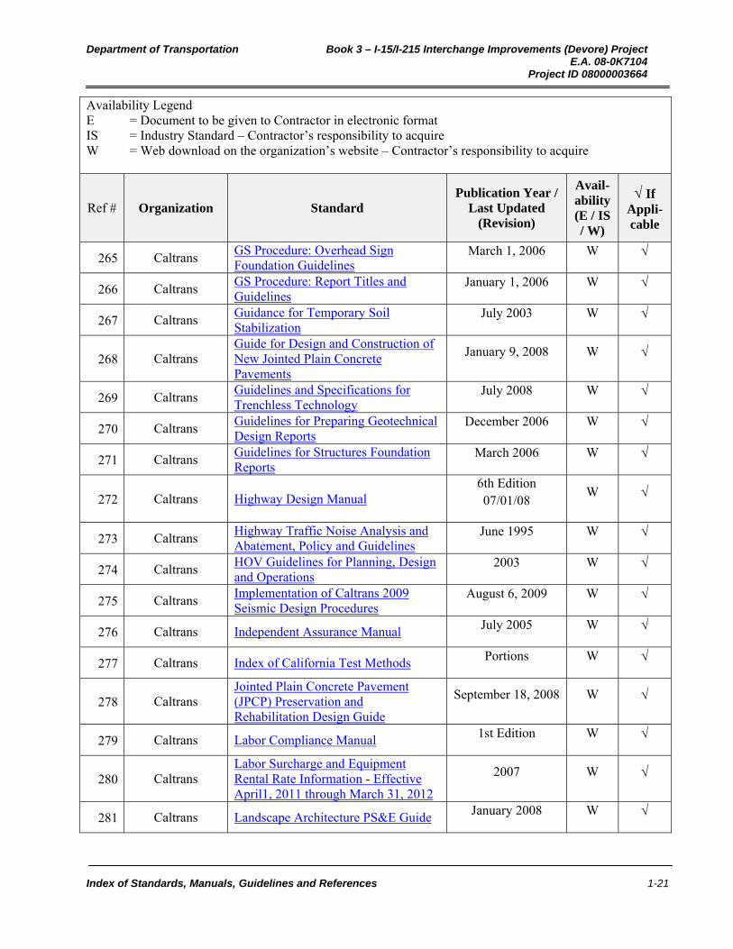
Availability Legend E = Document to be given to Contractor in electronic format IS = Industry Standard – Contractor’s responsibility to acquire W = Web download on the organization’s website – Contractor’s responsibility to acquire
Ref # Organization Standard Publication Year /
Last Updated (Revision)
Avail-ability (E / IS / W)
If Appli-cable
265 Caltrans GS Procedure: Overhead Sign Foundation Guidelines
March 1, 2006 W
266 Caltrans GS Procedure: Report Titles and Guidelines
January 1, 2006 W
267 Caltrans Guidance for Temporary Soil Stabilization
July 2003 W
268 Caltrans Guide for Design and Construction of New Jointed Plain Concrete Pavements
January 9, 2008 W
269 Caltrans Guidelines and Specifications for Trenchless Technology
July 2008 W
270 Caltrans Guidelines for Preparing Geotechnical Design Reports
December 2006 W
271 Caltrans Guidelines for Structures Foundation Reports
March 2006 W
272 Caltrans Highway Design Manual 6th Edition 07/01/08
W
273 Caltrans Highway Traffic Noise Analysis and Abatement, Policy and Guidelines
June 1995 W
274 Caltrans HOV Guidelines for Planning, Design and Operations
2003 W
275 Caltrans Implementation of Caltrans 2009 Seismic Design Procedures
August 6, 2009 W
276 Caltrans Independent Assurance Manual July 2005 W
277 Caltrans Index of California Test Methods Portions W
278 Caltrans Jointed Plain Concrete Pavement (JPCP) Preservation and Rehabilitation Design Guide
September 18, 2008 W
279 Caltrans Labor Compliance Manual 1st Edition W
280 Caltrans Labor Surcharge and Equipment Rental Rate Information - Effective April1, 2011 through March 31, 2012
2007 W
281 Caltrans Landscape Architecture PS&E Guide January 2008 W

Department of Transportation Book 3 – I-15/I-215 Interchange Improvements (Devore) Project E.A. 08-0K7104 Project ID 08000003664
Index of Standards, Manuals, Guidelines and References 1-22
Availability Legend E = Document to be given to Contractor in electronic format IS = Industry Standard – Contractor’s responsibility to acquire W = Web download on the organization’s website – Contractor’s responsibility to acquire
Ref # Organization Standard Publication Year /
Last Updated (Revision)
Avail-ability (E / IS / W)
If Appli-cable
282 Caltrans Life Cycle Cost Analysis Procedures Manual
November 2007 Updated
August 2010 W
283 Caltrans Local Agency Structure Representative (LASR) Guidelines August 2008 W
284 Caltrans LRFD Guidelines for the Seismic Design of Highway Bridges
November 2001 W
285 Caltrans Main Streets: Flexibility in Design & Operations
January 2005 W
286 Caltrans Maintenance Manual Volume 1 July 2006
W
287 Caltrans Maintenance Technical Advisory Guide (TAG)
October 2003 W
288 Caltrans Miscellaneous equipment rental rate book
08-01-08 03-31-09
W
289 Caltrans New Product Evaluation Guidelines June 1, 2008 W
290 Caltrans Office of Specially of Funded Projects (OSFP) Information and Procedures Guide
W
291 Caltrans Office of Structural Materials Practices and Procedures Manual April 2010 W
292 Caltrans Open Graded Friction Course Usage Guide
February 8, 2006 W
293 Caltrans OSFP Information and Procedure Guide
July 2007 W
294 Caltrans Outline of Field Construction Practices
January 2009 W
295 Caltrans Overhead and Roadside Sign Structures Reference Sheets
January 2006 W
296 Caltrans Oversight Engineer Field Guidelines June 2005 W
297 Caltrans Pavement Program Website W

Department of Transportation Book 3 – I-15/I-215 Interchange Improvements (Devore) Project E.A. 08-0K7104 Project ID 08000003664
Index of Standards, Manuals, Guidelines and References 1-23
Availability Legend E = Document to be given to Contractor in electronic format IS = Industry Standard – Contractor’s responsibility to acquire W = Web download on the organization’s website – Contractor’s responsibility to acquire
Ref # Organization Standard Publication Year /
Last Updated (Revision)
Avail-ability (E / IS / W)
If Appli-cable
298 Caltrans Pavement Tapers and Transitions Guide
December 31, 2008 W
299 Caltrans Pavement Technical Guidance W
300 Caltrans Pedestrian and Bicycle Facilities in California
July 2005 W
301 Caltrans Plans Preparation Manual January 2008 W
302 Caltrans Plans Preparation Manual Reference EZ Guide
March 2006 W
303 Caltrans Policy on High and Low Risk Underground Facilities Within Highway Rights of Way
January 1997 W
304 Caltrans Pre-Qualified Products List (Pending) Various W
305 Caltrans Prestress Manual January 2005 W
306 Caltrans Project Development Procedure Manual
7th Edition W
307 Caltrans Project Development Workflow Tasks Manual
October 2004 W
308 Caltrans Quality Control Manual for Hot Mix Asphalt for the Quality Control Quality Assurance Process
June 2009 W
309 Caltrans Ramp Meter Design Manual January 2000 W
310 Caltrans Ready to List and Construction Contract Award Guide (RTL Guide)
September 2008 W
311 Caltrans Right of Way Manual W
312 Caltrans Safety Manual W
313 Caltrans Sample Mitigation Monitoring Reporting Record (MMRR) form
W
314 Caltrans Sample Permits, Agreements, and Mitigation (PAM) form [xls]
W
315 Caltrans Seismic Design Criteria 2006 W
Department of Transportation Book 3 – I-15/I-215 Interchange Improvements (Devore) Project E.A. 08-0K7104 Project ID 08000003664
Index of Standards, Manuals, Guidelines and References 1-24
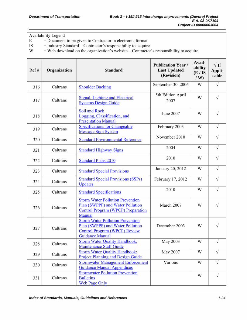
Availability Legend E = Document to be given to Contractor in electronic format IS = Industry Standard – Contractor’s responsibility to acquire W = Web download on the organization’s website – Contractor’s responsibility to acquire
Ref # Organization Standard Publication Year /
Last Updated (Revision)
Avail-ability (E / IS / W)
If Appli-cable
316 Caltrans Shoulder Backing September 30, 2006 W
317 Caltrans Signal, Lighting and Electrical Systems Design Guide
5th Edition April 2007
W
318 Caltrans Soil and Rock Logging, Classification, and Presentation Manual
June 2007 W
319 Caltrans Specifications for Changeable Message Sign System
February 2003 W
320 Caltrans Standard Environmental Reference November 2010 W
321 Caltrans Standard Highway Signs 2004 W
322 Caltrans Standard Plans 2010 2010 W
323 Caltrans Standard Special Provisions January 20, 2012 W
324 Caltrans Standard Special Provisions (SSPs) Updates
February 17, 2012 W
325 Caltrans Standard Specifications 2010 W
326 Caltrans
Storm Water Pollution Prevention Plan (SWPPP) and Water Pollution Control Program (WPCP) Preparation Manual
March 2007 W
327 Caltrans
Storm Water Pollution Prevention Plan (SWPPP) and Water Pollution Control Program (WPCP) Review Guidance Manual
December 2003 W
328 Caltrans Storm Water Quality Handbook: Maintenance Staff Guide
May 2003 W
329 Caltrans Storm Water Quality Handbook: Project Planning and Design Guide
May 2007 W
330 Caltrans Stormwater Management Enforcement Guidance Manual Appendices
Various W
331 Caltrans Stormwater Pollution Prevention Bulletins Web Page Only
W

Department of Transportation Book 3 – I-15/I-215 Interchange Improvements (Devore) Project E.A. 08-0K7104 Project ID 08000003664
Index of Standards, Manuals, Guidelines and References 1-25
Availability Legend E = Document to be given to Contractor in electronic format IS = Industry Standard – Contractor’s responsibility to acquire W = Web download on the organization’s website – Contractor’s responsibility to acquire
Ref # Organization Standard Publication Year /
Last Updated (Revision)
Avail-ability (E / IS / W)
If Appli-cable
332 Caltrans Stormwater Pollution Prevention Related College Courses Web Page Only
W
333 Caltrans Stormwater Pollution Prevention Training Courses + a video
W
334 Caltrans Stormwater Quality Preparation Manual Attachments SWPPP
March 1, 2007 W
335 Caltrans Stormwater Quality Templates and Samples
2007 W
336 Caltrans Structural Design Electronic Procedures
W
337 Caltrans Structural Detailing Standards June 2005 W
338 Caltrans Structure Document Request Guidelines
October 14, 2003 W
339 Caltrans Su Propiedad - Su Projecto de Transportacion
W
340 Caltrans Surveys Manual September 2006 W
341 Caltrans Tack Coat Guidelines July 2006 W
342 Caltrans Technical Advisory Guide (TAG) for Bonded Wearing Course Pilot Projects
October 2003 W
343 Caltrans Technical Advisory Guide for Microsurfacing Pilot Projects
October 2003 W
344 Caltrans Technical Noise Supplement October 1998 W
345 Caltrans The Plant Setback and Spacing Guide W
346 Caltrans Traffic Manual (Current) September 26, 2006 W
347 Caltrans Traffic Noise Analysis Protocol for New Highway Construction and Highway Reconstruction Projects
October 1998 W
348 Caltrans
Traffic Noise Analysis Protocol for New Highway Construction, Reconstruction and Retrofit Barrier Projects
August 14, 2006 W
Department of Transportation Book 3 – I-15/I-215 Interchange Improvements (Devore) Project E.A. 08-0K7104 Project ID 08000003664
Index of Standards, Manuals, Guidelines and References 1-26
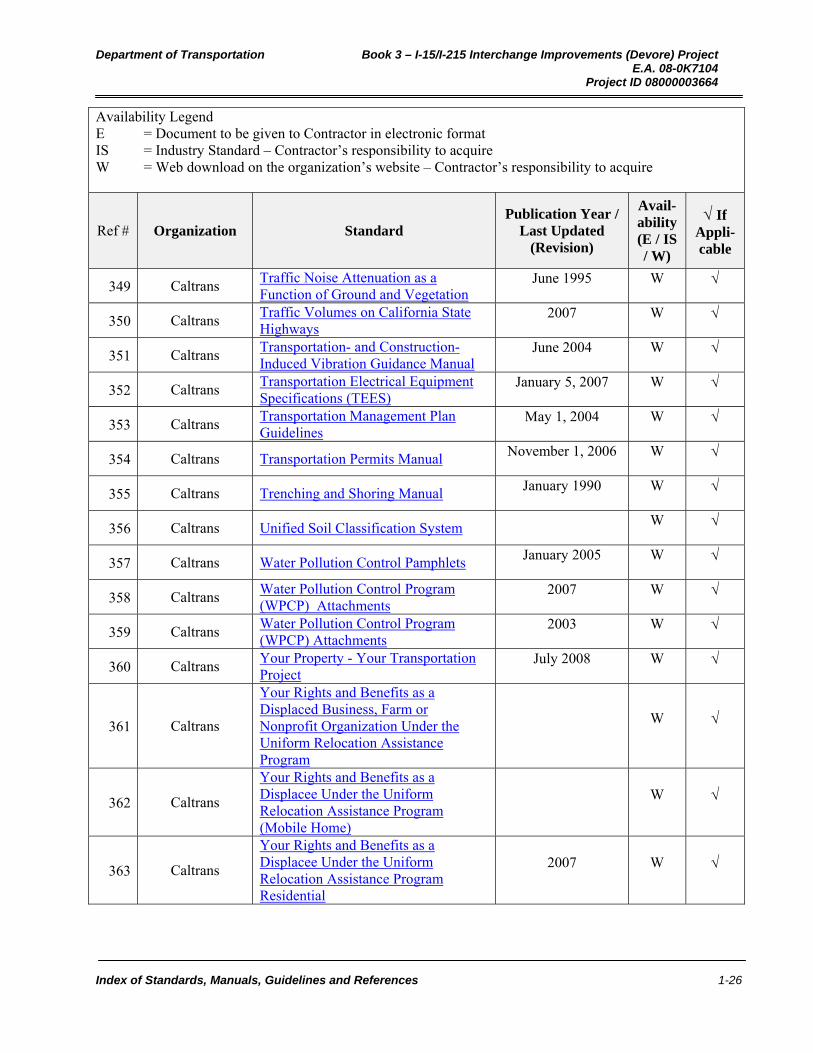
Availability Legend E = Document to be given to Contractor in electronic format IS = Industry Standard – Contractor’s responsibility to acquire W = Web download on the organization’s website – Contractor’s responsibility to acquire
Ref # Organization Standard Publication Year /
Last Updated (Revision)
Avail-ability (E / IS / W)
If Appli-cable
349 Caltrans Traffic Noise Attenuation as a Function of Ground and Vegetation
June 1995 W
350 Caltrans Traffic Volumes on California State Highways
2007 W
351 Caltrans Transportation- and Construction-Induced Vibration Guidance Manual
June 2004 W
352 Caltrans Transportation Electrical Equipment Specifications (TEES)
January 5, 2007 W
353 Caltrans Transportation Management Plan Guidelines
May 1, 2004 W
354 Caltrans Transportation Permits Manual November 1, 2006 W
355 Caltrans Trenching and Shoring Manual January 1990 W
356 Caltrans Unified Soil Classification System W
357 Caltrans Water Pollution Control Pamphlets January 2005 W
358 Caltrans Water Pollution Control Program (WPCP) Attachments
2007 W
359 Caltrans Water Pollution Control Program (WPCP) Attachments
2003 W
360 Caltrans Your Property - Your Transportation Project
July 2008 W
361 Caltrans
Your Rights and Benefits as a Displaced Business, Farm or Nonprofit Organization Under the Uniform Relocation Assistance Program
W
362 Caltrans
Your Rights and Benefits as a Displacee Under the Uniform Relocation Assistance Program (Mobile Home)
W
363 Caltrans
Your Rights and Benefits as a Displacee Under the Uniform Relocation Assistance Program Residential
2007 W
Department of Transportation Book 3 – I-15/I-215 Interchange Improvements (Devore) Project E.A. 08-0K7104 Project ID 08000003664
Index of Standards, Manuals, Guidelines and References 1-27
Availability Legend E = Document to be given to Contractor in electronic format IS = Industry Standard – Contractor’s responsibility to acquire W = Web download on the organization’s website – Contractor’s responsibility to acquire
Ref # Organization Standard Publication Year /
Last Updated (Revision)
Avail-ability (E / IS / W)
If Appli-cable
364 CPUC PUC General Orders, Codes, Laws, Policies, Rules of Practice & Procedure
Various W
365 EIA Electronics Industries Alliance (EIA) Standards
Various IS
366 EIA/TIA
Collaboration 455-171A-FOTP-171 June 1, 2001 IS
367 EIA/TIA
Collaboration Fiber Optic Test Procedure (FOTP) Standards
Various IS
368 Federal
Geographic Data Committee
FGDC Geospatial Standards Various IS
369 FHWA
Advance Course on Soil Slope Stability: Volume I, Slope Stability Manual FHWA-SA-94-005
April 1994 IS
370 FHWA
Advance Course on Soil Slope Stability: Volume II, Slope Stability Manual FHWA-SA-94-006
April 1994 IS
371 FHWA
An Analysis of Factors Contributing to "Walking Along Roadway" Crashes; Research Study and Guidelines for Sidewalks and Walkways FHWA RD-01-101
February 2002 W
372 FHWA BIKESAFE Bicycle Safety Guide FHWA-SA-05-006
May 2006 W
373 FHWA CBEAR - Bearing Capacity Analysis of Shallow Foundations Users ManualFHWA-SA-94-034
June 1982 W
374 FHWA
Checklist and Guidelines for Review of Geotechnical Reports and Preliminary Plans and Specifications FHWA-ED-88-053
February 2003 W
375 FHWA Code of Federal Regulations, Title 23 (Highways), Chapter 1, Part 752 Landscape and Roadside Development
2005 W
Department of Transportation Book 3 – I-15/I-215 Interchange Improvements (Devore) Project E.A. 08-0K7104 Project ID 08000003664
Index of Standards, Manuals, Guidelines and References 1-28
Availability Legend E = Document to be given to Contractor in electronic format IS = Industry Standard – Contractor’s responsibility to acquire W = Web download on the organization’s website – Contractor’s responsibility to acquire
Ref # Organization Standard Publication Year /
Last Updated (Revision)
Avail-ability (E / IS / W)
If Appli-cable
376 FHWA
Com624P – Laterally Loaded Pile Analysis Program for the Microcomputer Version 2.0 FHWA-SA-91-048
August 1993 W
377 FHWA
Corrosion/Degradation of Soil Reinforcements for Mechanically Stabilized Earth Walls and Reinforced Soil Slopes FHWA-NHI-00-044
September 2000 W
378 FHWA Culvert Inspection Manual FHWA-IP-86-2
July 1986
379 FHWA Design and Construction of Driven Pile Foundations, Volume I FHWA-HI-97-013
November 1998 W
380 FHWA Design and Construction of Driven Pile Foundations, Volumes II FHWA-HI-97-014
November 1988 W
381 FHWA Design Guidance Accommodating Bicycle and Pedestrian Travel: A Recommended Approach
W
382 FHWA Design Manual for Permanent Ground Anchor Walls FHWA-RD-97-130
September 1998
383 FHWA Design of Urban Highway Drainage FHWA-TS-79-225
August 1979 W
384 FHWA
Determination of Pile Driveability and Capacity from Penetration Tests Volume I FHWA-RD-96-179
May 1997 IS
385 FHWA
Determination of Pile Driveability and Capacity from Penetration Tests Volume II FHWA-RD-96-180
May 1997 IS
386 FHWA
Determination of Pile Driveability and Capacity from Penetration Tests Volume III FHWA-RD-96-181
May 1997 IS
387 FHWA Drilled and Grouted Micropiles: State of Practice Review Volume I FHWA-RD-96-016
July 1997 IS

Department of Transportation Book 3 – I-15/I-215 Interchange Improvements (Devore) Project E.A. 08-0K7104 Project ID 08000003664
Index of Standards, Manuals, Guidelines and References 1-29
Availability Legend E = Document to be given to Contractor in electronic format IS = Industry Standard – Contractor’s responsibility to acquire W = Web download on the organization’s website – Contractor’s responsibility to acquire
Ref # Organization Standard Publication Year /
Last Updated (Revision)
Avail-ability (E / IS / W)
If Appli-cable
388 FHWA Drilled and Grouted Micropiles: State of Practice Review Volume II FHWA-RD-96-017
July 1997 IS
389 FHWA Drilled and Grouted Micropiles: State of Practice Review Volume III FHWA-RD-96-018
July 1997 IS
390 FHWA Drilled and Grouted Micropiles: State of Practice Review Volume IV FHWA-RD-96-019
July 1997 IS
391 FHWA Drilled Shafts: Construction Procedures and Design Methods FHWA-IF-99-025
August 1999 W
392 FHWA
Drilled Shafts: Construction Procedures and LRFD Design Methods FHWA-NHI-10-016
May 2010 W
393 FHWA Durability Analysis of Aluminized Type 2 Corrugated Metal Pipe FHWA-RD-97-140
December 1996 W
394 FHWA
EMBANK- A Microcomputer Program to Determine One-Dimensional Compression Due to Embankment Loads FHWA-SA-92-045
May 1993 IS
395 FHWA Extrapolation of Pile Capacity From Non-Failed Load Tests FHWA-RD-99-170
December 1999 W
396 FHWA Flexibility in Highway Design FHWA-PD-97-062
W
397 FHWA Geocomposite Drains, Volume 1 FHWA-RD-86-171
October 1986 IS
398 FHWA Geocomposite Drains, Volume 2 FHWA-RD-86-172
October 1986 IS
399 FHWA Geosynthetic Design and Construction Guidelines FHWA-HI-95-038
April 1998 W
400 FHWA Geosynthetic Mechanically Stabilized Earth Slopes on Firm Foundations FHWA-SA-93-025
June 1989 IS
Department of Transportation Book 3 – I-15/I-215 Interchange Improvements (Devore) Project E.A. 08-0K7104 Project ID 08000003664
Index of Standards, Manuals, Guidelines and References 1-30
Availability Legend E = Document to be given to Contractor in electronic format IS = Industry Standard – Contractor’s responsibility to acquire W = Web download on the organization’s website – Contractor’s responsibility to acquire
Ref # Organization Standard Publication Year /
Last Updated (Revision)
Avail-ability (E / IS / W)
If Appli-cable
401 FHWA Geotechnical Engineering Circular No. 1 - Dynamic Compaction FHWA-SA-95-037
1995 W
402 FHWA Geotechnical Engineering Circular No. 2 - Earth Retaining Systems FHWA-SA-95-037
February 1997 IS
403 FHWA
Geotechnical Engineering Circular No. 3 - Earthquake Engineering for Highways, Design Examples, Volume 2 (ISDDC) FHWA-SA-97-077
May 1997 W
404 FHWA
Geotechnical Engineering Circular No. 3 - Earthquake Engineering for Highways, Design Principles, Volume 1 (ISDDC) FHWA-SA-97-076
May 1997 W
405 FHWA
Geotechnical Engineering Circular No. 5 Evaluation of Soil and Rock Properties FHWA-IF-02-034
April 2002 W
406 FHWA Geotechnical Engineering Circular No. 6 - Shallow Foundations FHWA-IF-02-054
September 2002 W
407 FHWA Geotechnical Engineering Circular No. 7 - Soil Nail Walls FHWA-IF-03-017
March 2003 W
408 FHWA Geotechnical Engineering Circular No. 8 - Design and Construction of Continuous Flight Auger Piles
2007 W
409 FHWA
Geotechnical Engineering Circular Number 4, Ground Anchors and Anchored Systems FHWA-IF-99-015
June 1999 W
410 FHWA Geotechnical Engineering Investigation Handbook
2nd Edition 2005 IS
411 FHWA Geotechnical Instrumentation FHWA-HI-98034
October 1998 IS
412 FHWA Geotechnical Publications FHWA-RD-00-167
December 2000 W

Department of Transportation Book 3 – I-15/I-215 Interchange Improvements (Devore) Project E.A. 08-0K7104 Project ID 08000003664
Index of Standards, Manuals, Guidelines and References 1-31
Availability Legend E = Document to be given to Contractor in electronic format IS = Industry Standard – Contractor’s responsibility to acquire W = Web download on the organization’s website – Contractor’s responsibility to acquire
Ref # Organization Standard Publication Year /
Last Updated (Revision)
Avail-ability (E / IS / W)
If Appli-cable
413 FHWA GT-1 Guidelines for the Design of Mechanically Stabilized Earth Walls with Inextensible Reinforcements
February 2008 IS
414 FHWA GT-15 - Geotechnical Differing Site Conditions FHWA-1996
May 2, 1996 W
415 FHWA
GT-16 Determination of Unknown Subsurface Bridge Foundations, NCHRP 21-5 Interim Report Summary FHWA-1998
December 1996 IS
416 FHWA
Guide for Selecting Manning's Roughness Coefficients for Natural Channels and Flood Plains FHWA-TS-84-204
April 1984 W
417 FHWA Guidelines for Cone Penetration Test - Performance and Design FHWA-TS-78-209
July 1977 IS
418 FHWA Handbook on Design and Construction of Drilled Shafts under Lateral Load FHWA-IP-84-11
1984 IS
419 FHWA High-Performance Concrete (HPC) Defined for Highway Structures
April 6, 2011 W
420 FHWA Highway Traffic Noise Analysis and Abatement, Policy and Guidelines
June 1995 W
421 FHWA Highway Utility Guide FHWA-SA-93-049
June 1993 W
422 FHWA Hollow Core Soil Nails State of the Practice
April 2006 W
423 FHWA How to Develop a Pedestrian Safety Action Plan FHWA-SA-05-12
May 2008 W
424 FHWA
Hydraulic Design Series No. 5 (HEC-5), Hydraulic Design of Highway Culverts FHWA-NHI-01-020
May 2005 W
425 FHWA
Hydraulic Design Series No. 9 (HEC-9), Debris Control Structures Evaluation and Countermeasures FHWA-IF-04-016
October 2005 W

Department of Transportation Book 3 – I-15/I-215 Interchange Improvements (Devore) Project E.A. 08-0K7104 Project ID 08000003664
Index of Standards, Manuals, Guidelines and References 1-32
Availability Legend E = Document to be given to Contractor in electronic format IS = Industry Standard – Contractor’s responsibility to acquire W = Web download on the organization’s website – Contractor’s responsibility to acquire
Ref # Organization Standard Publication Year /
Last Updated (Revision)
Avail-ability (E / IS / W)
If Appli-cable
426 FHWA Hydraulic Design Series Number 1, Hydraulics of Bridge Waterways FHWA-EPD-86-101
March 1978 W
427 FHWA Hydraulic Design Series Number 3, Design Charts for Open-Channel FlowFHWA-EPD-86-102
August 1961 W
428 FHWA
Hydraulic Engineering Circular Number 11 (HEC-11), Design of Riprap Revetment FHWA-IP-89-016
March 1989 W
429 FHWA
Hydraulic Engineering Circular Number 13 (HEC-13), Hydraulic Design of Improved Inlets for CulvertsFHWA-EFD-86-109
August 1972 W
430 FHWA
Hydraulic Engineering Circular Number 14 (HEC-14), Hydraulic Design of Energy Dissipaters for Culverts and Channels FHWA-NHI-06-086
July 2006 W
431 FHWA
Hydraulic Engineering Circular Number 15 (HEC-15), Design of Roadside Channels with Flexible Linings FHWA-NHI-05-114
September 2005 W
432 FHWA
Hydraulic Engineering Circular Number 17 (HEC-17), The Design of Encroachments on Flood Plains Using Risk Analysis FHWA-EPD-86-112
April 1981 W
433 FHWA
Hydraulic Engineering Circular Number 18 (HEC-18), Evaluating Scour at Bridges FHWA-NHI-01-001
May 2001 W
434 FHWA
Hydraulic Engineering Circular Number 2 (HEC-2), Highway Hydrology FHWA-NHI-02-001
October 2002 W

Department of Transportation Book 3 – I-15/I-215 Interchange Improvements (Devore) Project E.A. 08-0K7104 Project ID 08000003664
Index of Standards, Manuals, Guidelines and References 1-33
Availability Legend E = Document to be given to Contractor in electronic format IS = Industry Standard – Contractor’s responsibility to acquire W = Web download on the organization’s website – Contractor’s responsibility to acquire
Ref # Organization Standard Publication Year /
Last Updated (Revision)
Avail-ability (E / IS / W)
If Appli-cable
435 FHWA
Hydraulic Engineering Circular Number 21 (HEC-21), Design of Bridge Deck Drainage Systems FHWA-SA-92-010
May 1993 W
436 FHWA
Hydraulic Engineering Circular Number 22 (HEC-22), Urban Drainage Design Manual FHWA-NHI-01-021
August 2001 W
437 FHWA
Hydraulic Engineering Circular Number 23 (HEC-23), Bridge Scour and Stream Instability Countermeasures-Experience, Selection and Design
July 1997 W
438 FHWA
Hydraulic Engineering Circular Number 24 (HEC-24), Highway Stormwater Pump Station Design FHWA-NHI-01-007
February 2001 W
439 FHWA
Hydraulic Engineering Circular Number 4 (HEC-4), Introduction to Highway Hydraulics FHWA-NHI-01-019
August 2001 W
440 FHWA Hydraulics of Iowa DOT Slope-Tapered Pipe Culverts FHWA-RD-01-077
June 2001 W
441 FHWA Lateral Support Systems and Underpinning, Volume 1 FHWA-RD-75-128
April 1976 W
442 FHWA Lateral Support Systems and Underpinning, Volume 2 FHWA-RD-75-129
April 1976 W
443 FHWA Lateral Support Systems and Underpinning, Volume 3 FHWA-RD-75-130
April 1976 W
444 FHWA
Load and Resistance Factor Design (LRFD) for Highway Bridge Substructures FHWA-HI-98-032
1998 W
445 FHWA Load Transfer for Drilled Shafts in Intermediate Geomaterials FHWA_RD-95-038
November 1996 W

Department of Transportation Book 3 – I-15/I-215 Interchange Improvements (Devore) Project E.A. 08-0K7104 Project ID 08000003664
Index of Standards, Manuals, Guidelines and References 1-34
Availability Legend E = Document to be given to Contractor in electronic format IS = Industry Standard – Contractor’s responsibility to acquire W = Web download on the organization’s website – Contractor’s responsibility to acquire
Ref # Organization Standard Publication Year /
Last Updated (Revision)
Avail-ability (E / IS / W)
If Appli-cable
446 FHWA
Manual for Design & Construction Monitoring of Soil Nail Walls - CADD Files FHWA-SA-96-069R
October 1998 W
447 FHWA
Manual for Design & Construction Monitoring of Soil Nail Walls Appendices FHWA-SA-96-069R
October 1998 W
448 FHWA Manual for Design & Construction Monitoring of Soil Nail Walls FHWA-SA-96-069R
October 1998 W
449 FHWA Manual on Design and Construction of Driven Pile Foundations FHWA/DP-66-1
April 1996 IS
450 FHWA Manual on Design and Construction of Driven Pile Foundations FHWA-HI-97-013
November 1998 W
451 FHWA Manual on Design and Construction of Driven Pile Foundations FHWA-HI-97-014
November 1998 W
452 FHWA
Mechanically Stabilized Earth Walls and Reinforced Soil Slopes Design and Construction Guidelines FHWA-NHI-00-043
March 2001 W
453 FHWA Pedestrian Facilities Users Guide August 2000 W
454 FHWA PEDSAFE Pedestrian Safety Guide FHWA-SA-04-003
September 2004 W
455 FHWA Permanent Ground Anchors, Volume 1, Final Report FHWA-DP-90-068
April 1990 W
456 FHWA
Permanent Ground Anchors, Volume 2, Field Demonstration Project Summaries FHWA-DP-90-068
April 1990 W
457 FHWA Prefabricated Vertical Drains Volume I, Engineering Guidelines FHWA-RD-86-168
August 1986 W

Department of Transportation Book 3 – I-15/I-215 Interchange Improvements (Devore) Project E.A. 08-0K7104 Project ID 08000003664
Index of Standards, Manuals, Guidelines and References 1-35
Availability Legend E = Document to be given to Contractor in electronic format IS = Industry Standard – Contractor’s responsibility to acquire W = Web download on the organization’s website – Contractor’s responsibility to acquire
Ref # Organization Standard Publication Year /
Last Updated (Revision)
Avail-ability (E / IS / W)
If Appli-cable
458 FHWA Prefabricated Vertical Drains Volume II, Engineering Guidelines FHWA-RD-86-169
August 1986 IS
459 FHWA Prefabricated Vertical Drains Volume III, Engineering Guidelines FHWA-RD-86-170
August 1986 IS
460 FHWA Pressuremeter Test for Highway Applications FHWA-IP-89-008
July 1989 IS
461 FHWA Reinforced Soil Structures, Volume I: Design and Construction Guidelines FHWA-RD-89-043
November 1990 IS
462 FHWA
Reinforced Soil Structures, Volume II- Summary of Research and Systems Information FHWA-RD-89-044
November 1989 IS
463 FHWA
RSS Reinforced Slope Stability A Microcomputer Program User’s Manual FHWA-SA-96-039
January 1997 IS
464 FHWA Soil Nailing Field Inspectors Manual FHWA-SA-93-068
April 1994 W
465 FHWA Soils and Foundations Workshop Manual Volume I FHWA-NHI-06-088
3rd Edition December 2006
W
466 FHWA Soils and Foundations Workshop Manual Volume II FHWA-NHI-06-089
3rd Edition December 2006
W
467 FHWA South Dakota Culvert Inlet Design Coefficients FHWA-RD-01-076
February 1996 W
468 FHWA Spread Footings for Highway Bridges FHWA-RD-86-185
October 1987 IS
469 FHWA Static Testing of Deep Foundations FHWA-SA-91-042
February 1992 W
470 FHWA
Subsurface Investigations – Geotechnical Site Characterization; Reference Manual FHWA-NHI-01-031
May 2002 W

Department of Transportation Book 3 – I-15/I-215 Interchange Improvements (Devore) Project E.A. 08-0K7104 Project ID 08000003664
Index of Standards, Manuals, Guidelines and References 1-36
Availability Legend E = Document to be given to Contractor in electronic format IS = Industry Standard – Contractor’s responsibility to acquire W = Web download on the organization’s website – Contractor’s responsibility to acquire
Ref # Organization Standard Publication Year /
Last Updated (Revision)
Avail-ability (E / IS / W)
If Appli-cable
471 FHWA Subsurface Investigations FHWA-HI-97-021
November 1997 W
472 FHWA Subsurface Utility Engineering May 24, 2007 W
473 FHWA
Summary Report of Research on Permanent Ground Anchor Walls; Volume I FHWA-RD-98-065
September 1998 W
474 FHWA
Summary Report of Research on Permanent Ground Anchor Walls; Volume II FHWA-RD-98-066
September 1998 IS
475 FHWA
Summary Report of Research on Permanent Ground Anchor Walls; Volume III FHWA-RD-98-067
September 1998 W
476 FHWA
Summary Report of Research on Permanent Ground Anchor Walls; Volume IV FHWA-RD-98-068
September 1998 W
477 FHWA The Cone Penetration Test FHWA-SA-91-043
2007 W
478 FHWA The Osterberg CELL for Load Testing Drilled Shafts and Driven Piles FHWA-SA-94-035
February 1995 IS
479 FHWA Tiebacks FHWA-RD-82-047
July 1982 W
480 FHWA
Utility Relocation and Accommodation on Federal-Aid Highway FHWA-IF-03-014
6th Edition January 2003
W
481
Illuminating Engineering
Society of North America
Roadway Lighting, ANSI Approved July 1, 2000 IS
482
Institute of Transportation Engineering
(ITE)
Context Sensitive Solutions in Designing Major Urban Thoroughfares for Walkable Communities
January 2005 IS

Department of Transportation Book 3 – I-15/I-215 Interchange Improvements (Devore) Project E.A. 08-0K7104 Project ID 08000003664
Index of Standards, Manuals, Guidelines and References 1-37
Availability Legend E = Document to be given to Contractor in electronic format IS = Industry Standard – Contractor’s responsibility to acquire W = Web download on the organization’s website – Contractor’s responsibility to acquire
Ref # Organization Standard Publication Year /
Last Updated (Revision)
Avail-ability (E / IS / W)
If Appli-cable
483
Institute of Transportation Engineering
(ITE)
Enhancing Intersection Safety Through Roundabouts
December 2008 IS
484
Institute of Transportation Engineering
(ITE)
Freeway and Interchange Geometric Design Handbook
January 2005 IS
485
Institute of Transportation Engineering
(ITE)
Parking Generation 3rd Edition IS
486
Institute of Transportation Engineering
(ITE)
Traffic Engineering Handbook 6th Edition 2009 IS
487
Institute of Transportation Engineering
(ITE)
Traffic Engineering Handbook 5th Edition IS
488
Institute of Transportation Engineering
(ITE)
Transportation Impact Analyses for Site Development
January 2006 IS
489
Institute of Transportation Engineering
(ITE)
Transportation Planning Handbook 3rd Edition IS
490
Institute of Transportation Engineering
(ITE)
Trip Generation 8th Edition IS
491
Institute of Transportation Engineering
(ITE)
Trip Generation 7th Edition IS
492
Institute of Transportation Engineering
(ITE)
Trip Generation and Trip Generation Handbook
2nd Edition & 7th Edition
IS
Department of Transportation Book 3 – I-15/I-215 Interchange Improvements (Devore) Project E.A. 08-0K7104 Project ID 08000003664
Index of Standards, Manuals, Guidelines and References 1-38
Availability Legend E = Document to be given to Contractor in electronic format IS = Industry Standard – Contractor’s responsibility to acquire W = Web download on the organization’s website – Contractor’s responsibility to acquire
Ref # Organization Standard Publication Year /
Last Updated (Revision)
Avail-ability (E / IS / W)
If Appli-cable
493
Institute of Transportation Engineering
(ITE)
Urban Street Geometric Design Handbook
December 2008 IS
494 International Code Council
(ICC) International Building Code 2009 IS
495
International Municipal
Signal Association
IMSA Catalog on Cables
IMSA Specification No. 50-2 on Loop Detector Lead-In Cable
2007
February 1, 2001
W
496
International Society of
Arboriculture (ISA)
Guide for Plant Appraisal 9th Edition 2000 IS
497 ISO ISO 9000 October 16, 2005 IS
498 ISOA Guide for Plant Appraisal Workbook 2000 IS
499 Military
Specifications MIL-A-8625FC September 10, 1993 IS
500 National Fire
Protection Agency (NFPA)
National Electric Code Standards 2008 IS
501
National Spatial Data
Infrastructure (NSDI)
Geospatial Positioning Accuracy Standards, Part 3: National Standards for Spatial Data Accuracy, FGDC-STD-007.3-1998
1998 W
502 NCHRP Report 350, Recommended Procedures for the Safety Performance Evaluation of Highway Features
1993 W
503 NCHRP Synthesis 360, Rock-Socketed Shafts for Highway Structure Foundations
September 1, 2006 W
504 NCHRP Synthesis 368, Cone Penetration Testing
W

Department of Transportation Book 3 – I-15/I-215 Interchange Improvements (Devore) Project E.A. 08-0K7104 Project ID 08000003664
Index of Standards, Manuals, Guidelines and References 1-39
Availability Legend E = Document to be given to Contractor in electronic format IS = Industry Standard – Contractor’s responsibility to acquire W = Web download on the organization’s website – Contractor’s responsibility to acquire
Ref # Organization Standard Publication Year /
Last Updated (Revision)
Avail-ability (E / IS / W)
If Appli-cable
505 NCHRP
Web Document 16 - Improved Surface Drainage of Pavements – Final Report (Project I-29)
Proposed Design Guidelines for Reducing Hydroplaning on New and Rehabilitated Pavements - TRB
June 1998 IS
506 NEMA National Electrical Manufacturers Association (NEMA) Standards
Various IS
507
NEMA Joint Publication /
Insulated Cable Engineers
Association (ICEA)
NEMA WC57-2004 December 20, 2004 IS
508
NEMA Joint Publication/
Insulated Cable Engineers
Association (ICEA)
ANSI/NEMA WC70-2009
ANSI/NEMA WC 71-1999
NEMA WC 74-2006
June 8, 2009
January 1, 1999
January 1, 2006
IS
509 Statue California State Statutes XXXX IS
510 The Society for
Protective Coatings
QP2 Standard Procedure for Evaluating the Qualifications of Painting Contractors to Remove Hazardous Paint
Various IS
511 TIA 455-59-FOTP-59 February 1, 2000 IS
512 TIA 492AAAA November 1, 2009 IS
513 TIA 526-14-A-OFSTP-14 August 1, 1998 IS
Department of Transportation Book 3 – I-15/I-215 Interchange Improvements (Devore) Project E.A. 08-0K7104 Project ID 08000003664
Index of Standards, Manuals, Guidelines and References 1-40
Availability Legend E = Document to be given to Contractor in electronic format IS = Industry Standard – Contractor’s responsibility to acquire W = Web download on the organization’s website – Contractor’s responsibility to acquire
Ref # Organization Standard Publication Year /
Last Updated (Revision)
Avail-ability (E / IS / W)
If Appli-cable
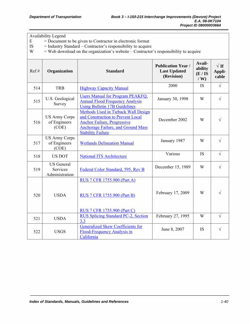
514 TRB Highway Capacity Manual 2000 IS
515 U.S. Geological
Survey
Users Manual for Program PEAKFQ, Annual Flood Frequency Analysis Using Bulletin 17B Guidelines
January 30, 1998 W
516 US Army Corps
of Engineers (COE)
Methods Used in Tieback Wall Design and Construction to Prevent Local Anchor Failure, Progressive Anchorage Failure, and Ground Mass Stability Failure
December 2002 W
517 US Army Corps
of Engineers (COE)
Wetlands Delineation Manual January 1987 W
518 US DOT National ITS Architecture Various IS
519 US General
Services Administration
Federal Color Standard, 595, Rev B December 15, 1989 W
520 USDA
RUS 7 CFR 1755.900 (Part A)
RUS 7 CFR 1755.900 (Part B)
RUS 7 CFR 1755.900 (Part C)
February 17, 2009 W
521 USDA RUS Splicing Standard PC-2, Section 3.3
February 27, 1995 W
522 USGS Generalized Skew Coefficients for Flood-Frequency Analysis in California
June 8, 2007 IS

Department of Transportation Book 3 – I-15/I-215 I/C Improvements (Devore) Project E.A. 08-0K7104 Project ID 08000003664
Modifications To Department (Caltrans) Manuals 2-1
2 MODIFICATIONS TO DEPARTMENT (CALTRANS) MANUALS
The following notes apply to the Caltrans Manuals used on this Project:
1. The Department (Caltrans) Manuals were created as an internal guidance document for use by various Department (Caltrans) personnel. As such, the Manuals are written as a guidance documents and not as mandatory requirements. For purposes of design-build projects, the Design-Builder shall assume that all provisions of the Manual, including the figures and tables, are mandatory and guidelines shall be assumed to be requirements. All words such as “should,” “may,” “must,” “might,” “could,” and “can” shall mean “shall” unless the context requires otherwise, as determined in the sole discretion of Department. The Design-Builder shall disregard qualifying words such as “usually,” “normally,” and “generally.” It shall be in Department’s sole discretion to determine when the context does not require a provision to be mandatory.
2. Department (Caltrans) Manuals are standard documents for use by Department (Caltrans) personnel. For purposes of design-build projects, the Design-Builder shall assume that all of the provisions of the Standards are requirements.
3. Individual manuals are available in electronic format. All the Department (Caltrans) manuals can be accessed at the following Web Site: http://caltrans-opac.ca.gov/publicat.htm
4. If the department (Caltrans) Manual expires during the course of the Project the Design-Builder shall contact Department to determine if they should continue to use the manual or if it will be replaced.
5. Any references related to pay items or quantities, measurement for payment, method of measurement, basis of payment, extra work, adjustment of unit prices, or similar phrases shall be disregarded by the Design-Builder , since the Contract Price is full compensation for the Work.
6. No changes have been made to provisions in the Manual that do not apply to design-build contracts, but that provide general information (e.g., descriptions of Department (Caltrans) divisions and their duties, descriptions of legal authority, or descriptions of internal Department (Caltrans) procedures); however, in some cases it may not be clear whether rights or responsibilities are applicable to the Design-Builder. If it is unclear whether specific provisions in the Manual are applicable to the Design-Builder, the Design-Builder shall raise the issue with Department and Department shall make that determination in its sole discretion.
7. The Design-Builder shall disregard the paragraphs within the manuals relating to questions. All questions shall be taken to the Department’s Contract Manager.
8. All references to the Engineer shall mean the Design-Builder unless otherwise directed by Department.
9. All references to the Agency shall mean Department (Caltrans), unless noted otherwise.
10. All references to Caltrans shall mean the Design-Builder, unless otherwise noted.
11. All references to Caltrans offices and personnel shall mean the Design-Builder’s similar offices and personnel.
12. When the Manual refers to an action being necessary or needed, the Design-Builder shall construe the action as required unless the context requires otherwise, as determined in the sole discretion of Department.
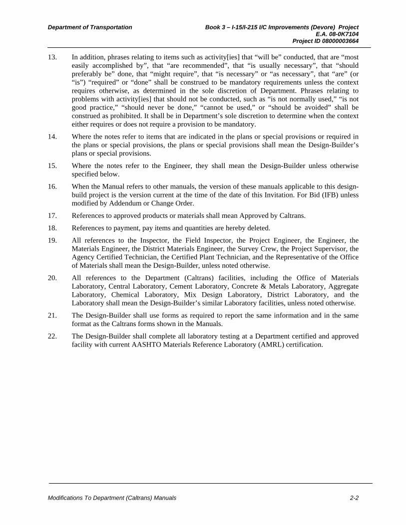
Department of Transportation Book 3 – I-15/I-215 I/C Improvements (Devore) Project E.A. 08-0K7104 Project ID 08000003664
Modifications To Department (Caltrans) Manuals 2-2
13. In addition, phrases relating to items such as activity[ies] that “will be” conducted, that are “most easily accomplished by”, that “are recommended”, that “is usually necessary”, that “should preferably be” done, that “might require”, that “is necessary” or “as necessary”, that “are” (or “is”) “required” or “done” shall be construed to be mandatory requirements unless the context requires otherwise, as determined in the sole discretion of Department. Phrases relating to problems with activity[ies] that should not be conducted, such as “is not normally used,” “is not good practice,” “should never be done,” “cannot be used,” or “should be avoided” shall be construed as prohibited. It shall be in Department’s sole discretion to determine when the context either requires or does not require a provision to be mandatory.
14. Where the notes refer to items that are indicated in the plans or special provisions or required in the plans or special provisions, the plans or special provisions shall mean the Design-Builder’s plans or special provisions.
15. Where the notes refer to the Engineer, they shall mean the Design-Builder unless otherwise specified below.
16. When the Manual refers to other manuals, the version of these manuals applicable to this design-build project is the version current at the time of the date of this Invitation. For Bid (IFB) unless modified by Addendum or Change Order.
17. References to approved products or materials shall mean Approved by Caltrans.
18. References to payment, pay items and quantities are hereby deleted.
19. All references to the Inspector, the Field Inspector, the Project Engineer, the Engineer, the Materials Engineer, the District Materials Engineer, the Survey Crew, the Project Supervisor, the Agency Certified Technician, the Certified Plant Technician, and the Representative of the Office of Materials shall mean the Design-Builder, unless noted otherwise.
20. All references to the Department (Caltrans) facilities, including the Office of Materials Laboratory, Central Laboratory, Cement Laboratory, Concrete & Metals Laboratory, Aggregate Laboratory, Chemical Laboratory, Mix Design Laboratory, District Laboratory, and the Laboratory shall mean the Design-Builder’s similar Laboratory facilities, unless noted otherwise.
21. The Design-Builder shall use forms as required to report the same information and in the same format as the Caltrans forms shown in the Manuals.
22. The Design-Builder shall complete all laboratory testing at a Department certified and approved facility with current AASHTO Materials Reference Laboratory (AMRL) certification.
Department of Transportation Book 3 – I-15/I-215 I/C Improvements (Devore) Project E.A. 08-0K7104 Project ID 08000003664
Modifications To Technical Memoranda 3-1
3 MODIFICATIONS TO TECHNICAL MEMORANDA (NOT USED)
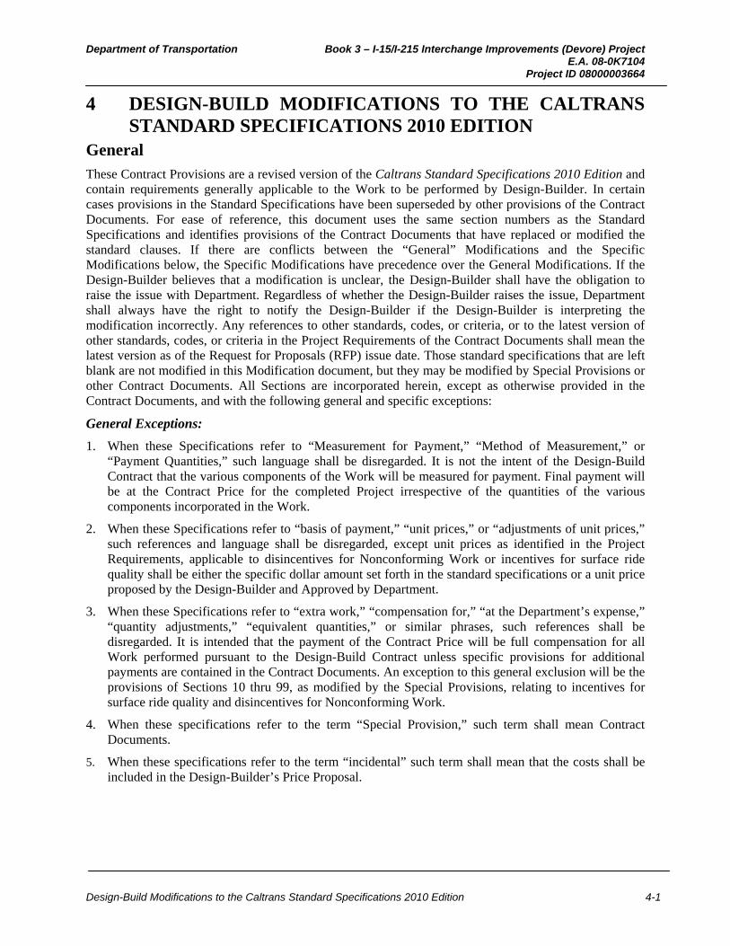
Department of Transportation Book 3 – I-15/I-215 Interchange Improvements (Devore) Project E.A. 08-0K7104 Project ID 08000003664
Design-Build Modifications to the Caltrans Standard Specifications 2010 Edition 4-1
4 DESIGN-BUILD MODIFICATIONS TO THE CALTRANS STANDARD SPECIFICATIONS 2010 EDITION
General These Contract Provisions are a revised version of the Caltrans Standard Specifications 2010 Edition and contain requirements generally applicable to the Work to be performed by Design-Builder. In certain cases provisions in the Standard Specifications have been superseded by other provisions of the Contract Documents. For ease of reference, this document uses the same section numbers as the Standard Specifications and identifies provisions of the Contract Documents that have replaced or modified the standard clauses. If there are conflicts between the “General” Modifications and the Specific Modifications below, the Specific Modifications have precedence over the General Modifications. If the Design-Builder believes that a modification is unclear, the Design-Builder shall have the obligation to raise the issue with Department. Regardless of whether the Design-Builder raises the issue, Department shall always have the right to notify the Design-Builder if the Design-Builder is interpreting the modification incorrectly. Any references to other standards, codes, or criteria, or to the latest version of other standards, codes, or criteria in the Project Requirements of the Contract Documents shall mean the latest version as of the Request for Proposals (RFP) issue date. Those standard specifications that are left blank are not modified in this Modification document, but they may be modified by Special Provisions or other Contract Documents. All Sections are incorporated herein, except as otherwise provided in the Contract Documents, and with the following general and specific exceptions:
General Exceptions:
1. When these Specifications refer to “Measurement for Payment,” “Method of Measurement,” or “Payment Quantities,” such language shall be disregarded. It is not the intent of the Design-Build Contract that the various components of the Work will be measured for payment. Final payment will be at the Contract Price for the completed Project irrespective of the quantities of the various components incorporated in the Work.
2. When these Specifications refer to “basis of payment,” “unit prices,” or “adjustments of unit prices,” such references and language shall be disregarded, except unit prices as identified in the Project Requirements, applicable to disincentives for Nonconforming Work or incentives for surface ride quality shall be either the specific dollar amount set forth in the standard specifications or a unit price proposed by the Design-Builder and Approved by Department.
3. When these Specifications refer to “extra work,” “compensation for,” “at the Department’s expense,” “quantity adjustments,” “equivalent quantities,” or similar phrases, such references shall be disregarded. It is intended that the payment of the Contract Price will be full compensation for all Work performed pursuant to the Design-Build Contract unless specific provisions for additional payments are contained in the Contract Documents. An exception to this general exclusion will be the provisions of Sections 10 thru 99, as modified by the Special Provisions, relating to incentives for surface ride quality and disincentives for Nonconforming Work.
4. When these specifications refer to the term “Special Provision,” such term shall mean Contract Documents.
5. When these specifications refer to the term “incidental” such term shall mean that the costs shall be included in the Design-Builder’s Price Proposal.

Department of Transportation Book 3 – I-15/I-215 Interchange Improvements (Devore) Project E.A. 08-0K7104 Project ID 08000003664
Design-Build Modifications to the Caltrans Standard Specifications 2010 Edition 4-2
A. Section 1 through 9 - General Provisions – Specific Modifications
Section 1 General
1-1.01 GENERAL This section is applicable to this project.
1-1.02 STYLE VARIATIONS This section is applicable to this project.
1-1.03–1-1.04 RESERVED
1-1.05 REFERENCES This section is deleted in its entirety. Provisions regarding “References” in this section are set forth in Book 1, Section 1 “Contract Components; Interpretation of Contract Documents” of the Contract Documents.
1-1.06 ABBREVIATIONS This section is applicable to this project.
1-1.07 DEFINITIONS
1-1.07A General Interpret terms as defined in the Contract documents. References to “Bid Item List” shall mean Price Proposal.
1-1.07B Glossary This section is applicable to this project.
1-1.08 DISTRICTS
This section is applicable to this project.
1-1.09 FREEZE-THAW AREAS
This section is applicable to this project.
1-1.10 RESERVED
1-1.11 WEB SITES, ADDRESSES, AND TELEPHONE NUMBERS
This section is applicable to this project.
1-1.12 MISCELLANY
Make checks and bonds payable to the Department of Transportation.
1-1.13–1-1.15 RESERVED
Department of Transportation Book 3 – I-15/I-215 Interchange Improvements (Devore) Project E.A. 08-0K7104 Project ID 08000003664
Design-Build Modifications to the Caltrans Standard Specifications 2010 Edition 4-3
Section 2 Bidding
This section is deleted in its entirety. Provisions regarding “Bidding” are set forth in the Instructions to Proposers (ITP) of the Contract Documents.
Department of Transportation Book 3 – I-15/I-215 Interchange Improvements (Devore) Project E.A. 08-0K7104 Project ID 08000003664
Design-Build Modifications to the Caltrans Standard Specifications 2010 Edition 4-4
Section 3 Contract Award and Execution
This section is deleted in its entirety. Provisions regarding “Contract Award and Execution” are set forth in the Instruction to Proposers of the Contract Documents.

Department of Transportation Book 3 – I-15/I-215 Interchange Improvements (Devore) Project E.A. 08-0K7104 Project ID 08000003664
Design-Build Modifications to the Caltrans Standard Specifications 2010 Edition 4-5
Section 4 Scope of Work
4-1.01 GENERAL Section 4 includes specifications related to the scope of work.
4-1.02 INTENT The Contract intent is to provide for work completion using the best general practices.
Nothing in the specifications voids the Contractor's public safety responsibilities.
4-1.03 WORK DESCRIPTION This section is deleted in its entirety. Provisions regarding “Work Description” in this section are set forth in the Contract Documents.
4-1.04 USE OF MATERIALS FOUND ON THE JOB SITE This section is deleted in its entirety. Any materials required to be removed from the Project shall become the property of the Design-Builder and shall be disposed of at an appropriate off-site disposal facility provided by the Design-Builder unless otherwise provided in the Contract Documents.
4-1.05 CHANGES AND EXTRA WORK
4-1.05A General This section is deleted in its entirety. Provisions regarding “General” in this section are set forth in Book 1, Section 13 “Changes in the Work” of the Contract Documents.
4-1.05B Work-Character Changes This section is deleted in its entirety. Provisions regarding “Work-Character Changes” in this section are set forth in Book 1, Section 13 “Changes in the Work” of the Contract Documents.
4-1.06 DIFFERING SITE CONDITIONS (23 CFR 635.109)
4-1.06A General Reserved
4-1.06B Contractor's Notification This section is deleted in its entirety. Provisions regarding “Contractor’s Notification” in this section are set forth in Book 1, Section 13 “Changes in the Work” of the Contract Documents.
4-1.06C Engineer's Investigation and Decision This section is deleted in its entirety. Provisions regarding “Engineer’s Investigation and Decision” in this section are set forth in Book 1, Section 13 “Changes in the Work” of the Contract Documents.
4-1.07 VALUE ENGINEERING
4-1.07A General
Reserved
4-1.07B Value Engineering Change Proposal
This section is deleted in its entirety.
4-1.07C Value Analysis Workshop
This section is deleted in its entirety.

Department of Transportation Book 3 – I-15/I-215 Interchange Improvements (Devore) Project E.A. 08-0K7104 Project ID 08000003664
Design-Build Modifications to the Caltrans Standard Specifications 2010 Edition 4-6
4-1.08–4-1.12 RESERVED
4-1.13 CLEANUP
This section is deleted in its entirety. Provisions regarding “Cleanup” in this section are set forth in Book 1, Section 20 “Acceptance of Project” of the Contract Documents.

Department of Transportation Book 3 – I-15/I-215 Interchange Improvements (Devore) Project E.A. 08-0K7104 Project ID 08000003664
Design-Build Modifications to the Caltrans Standard Specifications 2010 Edition 4-7
Section 5 Control of Work
5-1.01 GENERAL This section is applicable to this project.
5-1.02 CONTRACT COMPONENTS This section is hereby deleted in its entirety. Provisions regarding “Contract Components” in this section are set forth in the Book 1, Section 1 Contract Components; Interpretation of Contract Documents.
5-1.03 ENGINEER'S AUTHORITY This section is hereby deleted in its entirety. Provisions regarding “Engineer’s Authority” in this section are set forth in Book 1, Section 5 “Control of Work” of the Contract Documents. Department has the authority by written order to suspend the Work wholly or in part for the reasons delineated in Book 1, Section 15 “Termination for Convenience” of the Contract Documents. Failure to enforce a contract provision does not waive enforcement of any contract provision.
5-1.04–5-1.05 RESERVED
5-1.06 PROTESTS This section is hereby deleted in its entirety. Provisions regarding “Protests” in this section are set forth in Book 1, Section 13 “Changes in the Work” of the Contract Documents.
5-1.07–5-1.08 RESERVED
5-1.09 PARTNERING
5-1.09A General This section is hereby deleted in its entirety. Provisions regarding “General” in this section are set forth in Book 1, Section 19 “Partnering, Dispute Resolution” of the Contract Documents. 5-1.09B Partnering Facilitator, Workshops, and Monthly Evaluation Surveys This section is hereby deleted in its entirety. Provisions regarding “Partnering Facilitator, Workshops, and Monthly Evaluation Surveys” in this section are set forth in Book 1, Section 19 “Partnering, Dispute Resolution” of the Contract Documents.
5-1.09C Training in Partnering Skills Development This section is hereby deleted in its entirety. Provisions regarding “Training in Partnering Skills Development” in this section are set forth in Book 1, Section 19 “Partnering, Dispute Resolution” of the Contract Documents.
5-1.09D Payment This section is hereby deleted in its entirety. Provisions regarding “Payment” in this section are set forth in Book 1, Section 19 “Partnering, Dispute Resolution” of the Contract Documents.
5-1.10–5-1.11 RESERVED
5-1.12 ASSIGNMENT This section is hereby deleted in its entirety. Provisions regarding “Assignment” in this section are set forth in Book 1, Section 23 “Miscellaneous Provisions” of the Contract Documents.
5-1.13 SUBCONTRACTING
5-1.13A General This section is applicable to this project.
Department of Transportation Book 3 – I-15/I-215 Interchange Improvements (Devore) Project E.A. 08-0K7104 Project ID 08000003664
Design-Build Modifications to the Caltrans Standard Specifications 2010 Edition 4-8
5-1.13B Disadvantaged Business Enterprises 5-1.13B(1) General This section is hereby deleted in its entirety. Provisions regarding “General” in this section are set forth in Book 1, Section 7 “Equal Employment opportunity; Subcontracts; Labor” of the Contract Documents.
5-1.13B(2) Underutilized Disadvantaged Business Enterprises This section is hereby deleted in its entirety. Provisions regarding “Underutilized Disadvantaged Business Enterprises” in this section are set forth in Book 1, Section 7 “Equal Employment opportunity; Subcontracts; Labor” of the Contract Documents.
5-1.13C Disabled Veteran Business Enterprises This section is hereby deleted in its entirety.
5-1.13D Non–Small Businesses This section is hereby deleted in its entirety.
5-1.13E–5-1.13I Reserved
5-1.14–5-1.15 RESERVED
5-1.16 REPRESENTATIVE This section is hereby deleted in its entirety. Provisions regarding “Representative” in this section are set forth in Book 1, Section 23 “Miscellaneous Provisions” of the Contract Documents.
5-1.17 CHARACTER OF WORKERS This section is hereby deleted in its entirety. Provisions regarding “Character of Workers” in this section are set forth in Book 1, Section 7 “Equal Employment opportunity; Subcontracts; Labor” of the Contract Documents.
5-1.18–5.19 RESERVED
5-1.20 COORDINATION WITH OTHER ENTITIES
5-1.20A General This section is applicable to this project.
5-1.20B Permits, Licenses, Agreements, and Certifications 5-1.20B(1) General This section is applicable to this project.
5-1.20B(2) Before Award This section is applicable to this project.
5-1.20B(3) After Award This section is applicable to this project.
5-1.20B(4) Contractor–Property Owner Agreement This section is applicable to this project.
5-1.20C Railroad Relations Reserved
Department of Transportation Book 3 – I-15/I-215 Interchange Improvements (Devore) Project E.A. 08-0K7104 Project ID 08000003664
Design-Build Modifications to the Caltrans Standard Specifications 2010 Edition 4-9
5-1.20D–5-1.20F Reserved
5-1.21–5-1.22 RESERVED
5-1.23 SUBMITTALS
5-1.23A General This section is hereby deleted in its entirety. Provisions regarding “General” in this section are set forth in Book 2, Section 2 “Project Management” of the Contract Documents.
5-1.23B Action Submittals 5-1.23B(1) General This section is hereby deleted in its entirety. Provisions regarding “General” in this section are set forth in Book 2, Section 2 “Project Management” of the Contract Documents.
5-1.23B(2) Shop Drawings This section is hereby deleted in its entirety. Provisions regarding “Shop Drawings” in this section are set forth in Book 2, Section 2 “Project Management” and Section 13 “Structures” of the Contract Documents.
5-1.23B(3) Product Data Reserved
5-1.23B(4) Samples Reserved
5-1.23B(5) Test Samples This section is applicable to this project.
5-1.23B(6) Quality Control Plans This section is hereby deleted in its entirety. Provisions regarding “Quality Control Plans” in this section are set forth in Book 2, Section 2 “Project Management”” of the Contract Documents.
5-1.23B(7) Work Plans Reserved
5-1.23C Informational Submittals This section is applicable to this project.
5-1.24–5-1.25 RESERVED
5-1.26 CONSTRUCTION SURVEYS This section is hereby deleted in its entirety. Provisions regarding “Construction Surveys” in this section are set forth in Book 2, Section 9 “Land Surveying” of the Contract Documents.
5-1.27 RECORDS
5-1.27A General Reserved
5-1.27B Record Retention This section is hereby deleted in its entirety. Provisions regarding “Record Retention” in this section are set forth in Book 1, Section 22 “Documents and Records” of the Contract Documents.
5-1.27C Record Inspection, Copying, and Auditing This section is hereby deleted in its entirety. Provisions regarding “Record Inspection, Copying, and Auditing” in this section are set forth in Book 1, Section 22 “Documents and Records” of the Contract Documents.

Department of Transportation Book 3 – I-15/I-215 Interchange Improvements (Devore) Project E.A. 08-0K7104 Project ID 08000003664
Design-Build Modifications to the Caltrans Standard Specifications 2010 Edition 4-10
5-1.27D Cost Accounting Records This section is hereby deleted in its entirety. Provisions regarding “Cost Accounting Records” in this section are set forth in Book 1, Section 22 “Documents and Records” of the Contract Documents.
5-1.27E Change Order Bills This section is hereby deleted in its entirety. Provisions regarding “Change Order Bills” in this section are set forth in Book 1, Section 13 “Changes in the Work” of the Contract Documents.
5-1.28–5-1.29 RESERVED
5-1.30 NONCOMPLIANT AND UNAUTHORIZED WORK This section is hereby deleted in its entirety. Provisions regarding “Noncompliant and Unauthorized Work” in this section are set forth in Book 1, Section 5 “Control of Work” of the Contract Documents.
5-1.31 JOB SITE APPEARANCE This section is applicable to this project.
5-1.32 AREAS FOR USE This section is applicable to this project. References to Section 7-1.05 shall mean Book 1, Section 18 “Indemnification” of the Contract Documents.
5-1.33 EQUIPMENT This section is applicable to this project.
5-1.34–5-1.35 RESERVED
5-1.36 PROPERTY AND FACILITY PRESERVATION
5-1.36A General This section is hereby deleted in its entirety. Provisions regarding “General” in this section are set forth in Book 1, Section 10 “Risk of Loss” of the Contract Documents.
5-1.36B Landscape This section is applicable to this project.
5-1.36C Railroad Property This section is hereby deleted in its entirety. Provisions regarding “Railroad Property” in this section are set forth in Book 1, Section 2 “Obligations of Design-Builder” of the Contract Documents.
5-1.36D Nonhighway Facilities This section is applicable to this project.
5-1.37 MAINTENANCE AND PROTECTION
5-1.37A General This section is applicable to this project.
5-1.37B Load Limits 5-1.37B(1) General This section is applicable to this project.5-1.37B(2) Increased Load Carrying Capacity This section is applicable to this project.
5-1.37B(3) Material Hauling Equipment Lane on Bridges This section is applicable to this project.

Department of Transportation Book 3 – I-15/I-215 Interchange Improvements (Devore) Project E.A. 08-0K7104 Project ID 08000003664
Design-Build Modifications to the Caltrans Standard Specifications 2010 Edition 4-11
5-1.38 MAINTENANCE AND PROTECTION RELIEF This section is hereby deleted in its entirety. Provisions regarding “Maintenance and Protection Relief” in this section are set forth in Book 1, Section 10 “Risk of Loss” of the Contract Documents.
5-1.39 DAMAGE REPAIR AND RESTORATION
5-1.39A General This section is hereby deleted in its entirety. Provisions regarding “General” in this section are set forth in Book 1, Section 10 “Risk of Loss” of the Contract Documents.
5-1.39B Damage Caused by an Act of God This section is hereby deleted in its entirety. Provisions regarding “Damage Caused by an Act of God” in this section are set forth in Book 1, Section 13 “Changes in the Work” of the Contract Documents.
5-1.39C Landscape Damage 5-1.39C(1) General This section is applicable to this project.
5-1.39C(2) Plant Establishment Period of 3 Years or More This section is applicable to this project.
5-1.40–5-1.41 RESERVED
5-1.42 REQUESTS FOR INFORMATION This section is applicable to this project.
5-1.43 POTENTIAL CLAIMS AND DISPUTE RESOLUTION
5-1.43A General This section is hereby deleted in its entirety. Provisions regarding “General” in this section are set forth in Book 1, Section 13 “Changes in the Work” and Book 1, Section 19 “Partnering, Dispute Resolution” of the Contract Documents.
5-1.43B Initial Potential Claim Record This section is hereby deleted in its entirety. Provisions regarding “Initial Potential Claim Record” in this section are set forth in Book 1, Section 13 “Changes in the Work” of the Contract Documents.
5-1.43C Supplemental Potential Claim Record This section is hereby deleted in its entirety. Provisions regarding “Supplemental Potential Claim Record” in this section are set forth in Book 1, Section 13 “Changes in the Work” of the Contract Documents.
5-1.43D Full and Final Potential Claim Record This section is hereby deleted in its entirety. Provisions regarding “Full and Final Potential Claim Record” in this section are set forth in Book 1, Section 13 “Changes in the Work” of the Contract Documents.
5-1.43E Alternative Dispute Resolution 5-1.43E(1) General
5-1.43E(1)(a) General
This section is hereby deleted in its entirety. Provisions regarding “General” in this section are set forth in Book 1, Section 19 “Partnering, Dispute Resolution” of the Contract Documents.
Department of Transportation Book 3 – I-15/I-215 Interchange Improvements (Devore) Project E.A. 08-0K7104 Project ID 08000003664
Design-Build Modifications to the Caltrans Standard Specifications 2010 Edition 4-12
5-1.43E(1)(b) Establishment of Procedures
This section is hereby deleted in its entirety. Provisions regarding “Establishment of Procedures” in this section are set forth in Book 1, Section 19 “Partnering, Dispute Resolution” of the Contract Documents.
5-1.43E(1)(c) Dispute Meetings
This section is hereby deleted in its entirety. Provisions regarding “Dispute Meetings” in this section are set forth in Book 1, Section 19 “Partnering, Dispute Resolution” of the Contract Documents.
5-1.43E(1)(d) Informal Dispute Meetings
This section is hereby deleted in its entirety. Provisions regarding “Informational Dispute Meetings” in this section are set forth in Book 1, Section 19 “Partnering, Dispute Resolution” of the Contract Documents.
5-1.43E(1)(e) Recommendations
This section is hereby deleted in its entirety. Provisions regarding “Recommendations” in this section are set forth in Book 1, Section 19 “Partnering, Dispute Resolution” of the Contract Documents.
5-1.43E(1)(f) Completion of Alternative Dispute Resolution
This section is hereby deleted in its entirety. Provisions regarding “Completion of Alternative Dispute Resolution” in this section are set forth in Book 1, Section 19 “Partnering, Dispute Resolution” of the Contract Documents.
5-1.43E(1)(g) Payment
This section is hereby deleted in its entirety. Provisions regarding “Payment” in this section are set forth in Book 1, Section 19 “Partnering, Dispute Resolution” of the Contract Documents.
5-1.43E(2) Dispute Resolution Advisor
5-1.43E(2)(a) General
This section is not applicable and hereby deleted in its entirety.
5-1.43E(2)(b) DRA Selection
This section is not applicable and hereby deleted in its entirety.
5-1.43E(2)(c) DRA Replacement
This section is not applicable and hereby deleted in its entirety.
5-1.43E(2)(d) DRA Traditional Dispute Meeting
This section is not applicable and hereby deleted in its entirety.
5-1.43E(3) Dispute Resolution Board
5-1.43E(3)(a) General
This section is hereby deleted in its entirety. Provisions regarding “General” in this section are set forth in Book 1, Section 19 “Partnering, Dispute Resolution” of the Contract Documents.
5-1.43E(3)(b) DRB Member Selection
This section is hereby deleted in its entirety. Provisions regarding “DRB Member Selection” in this section are set forth in Book 1, Section 19 “Partnering, Dispute Resolution” of the Contract Documents.
Department of Transportation Book 3 – I-15/I-215 Interchange Improvements (Devore) Project E.A. 08-0K7104 Project ID 08000003664
Design-Build Modifications to the Caltrans Standard Specifications 2010 Edition 4-13
5-1.43E(3)(c) DRB Member Replacement
This section is hereby deleted in its entirety. Provisions regarding “DRB Member Replacement” in this section are set forth in Book 1, Section 19 “Partnering, Dispute Resolution” of the Contract Documents.
5-1.43E(3)(d) DRB Progress Meetings
This section is hereby deleted in its entirety. Provisions regarding “DRB Progress Meeting” in this section are set forth in Book 1, Section 19 “Partnering, Dispute Resolution” of the Contract Documents.
5-1.43E(3)(e) DRB Traditional Dispute Meeting
This section is hereby deleted in its entirety. Provisions regarding “DRB Traditional Dispute Meeting” in this section are set forth in Book 1, Section 19 “Partnering, Dispute Resolution” of the Contract Documents.
5-1.43F Reserved
5-1.44–5-1.45 RESERVED
5-1.46 FINAL INSPECTION AND CONTRACT ACCEPTANCE This section is hereby deleted in its entirety. Provisions regarding “Final Inspection and Contract Acceptance” in this section are set forth in Book 1, Section 20 “Acceptance of Project” of the Contract Documents.
5-1.47–5-1.50 RESERVED

Department of Transportation Book 3 – I-15/I-215 Interchange Improvements (Devore) Project E.A. 08-0K7104 Project ID 08000003664
Design-Build Modifications to the Caltrans Standard Specifications 2010 Edition 4-14
Section 6 Control of Material
6-1 GENERAL
6-1.01 GENERAL Section 6 includes specifications related to control of materials.
6-2 MATERIAL SOURCE
6-2.01 GENERAL This section is applicable to this project.
6-2.02 MATERIAL SOURCE This section is applicable to this project.
6-2.03 DEPARTMENT-FURNISHED MATERIALS This section is applicable to this project.
6-2.04 LOCAL MATERIALS This section is hereby deleted in its entirety. Provisions regarding “Local Materials” in this section are set forth in Book 1, Section 5 “Control of Work” of the Contract Documents.
6-2.05 BUY AMERICA
6-2.05A General Reserved
6-2.05B Crumb Rubber (Pub Res Code § 42703(D)) This section is applicable to this project.
6-2.05C Steel and Iron Materials (23 CFR 635.410) This section is applicable to this project.
6-3 QUALITY
6-3.01 GENERAL This section is applicable to this project.
6-3.02 SPECIFIC BRAND OR TRADE NAME AND SUBSTITUTION This section is hereby deleted in its entirety.
6-3.03 AUTHORIZED LABORATORY LISTS This section is applicable to this project.
6-3.04 QUALITY CONTROL This section is applicable to this project.
6-3.05 QUALITY ASSURANCE
6-3.05A General This section is applicable to this project.
6-3.05B Source Inspection Expense Deductions This section is applicable to this project.
6-3.05C Material Source Inspection and Testing This section is applicable to this project.
Department of Transportation Book 3 – I-15/I-215 Interchange Improvements (Devore) Project E.A. 08-0K7104 Project ID 08000003664
Design-Build Modifications to the Caltrans Standard Specifications 2010 Edition 4-15
6-3.05D Job Site Inspection and Testing This section is applicable to this project.
6-3.05E Certificates of Compliance This section is applicable to this project.
6-3.05F Test Data, Test Reports, and Evaluation Reports Reserved
6-3.05G Test Samples This section is applicable to this project.
6-3.05H Reserved
6-3.05I Authorized Facility Audit Lists This section is applicable to this project.
6-3.05J Quality Control Plans Reserved
6-3.05K Authorized Material Lists This section is applicable to this project.
6-3.05L Authorized Material Source Lists This section is applicable to this project.
6-3.06 GUARANTEE This section is hereby deleted in its entirety. Provisions regarding “Guarantee” in this section are set forth in Book 1, Section 21 “Warranties” of the Contract Documents.
Department of Transportation Book 3 – I-15/I-215 Interchange Improvements (Devore) Project E.A. 08-0K7104 Project ID 08000003664
Design-Build Modifications to the Caltrans Standard Specifications 2010 Edition 4-16
Section 7 Legal Relations and Responsibility to the Public
7-1.01 GENERAL This Section is applicable to this project.
7-1.02 LAWS
7-1.02A General This section is applicable to this project.
7-1.02B U.S. Fair Labor Standards Act This section is applicable to this project.
7-1.02C Emissions Reduction This section is applicable to this project.
7-1.02D–7-1.02H Reserved
7-1.02I Government Code 7-1.02I(1) General Reserved
7-1.02I(2) Nondiscrimination This section is applicable to this project.
7-1.02J Reserved
7-1.02K Labor Code 7-1.02K(1) General This section is applicable to this project.
7-1.02K(2) Wages This section is applicable to this project.
7-1.02K(3) Certified Payroll Records (Labor Code § 1776) This section is applicable to this project.
7-1.02K(4) Apprentices This section is applicable to this project.
7-1.02K(5) Working Hours This section is applicable to this project.
7-1.02K(6) Occupational Safety and Health Standards
7-1.02K(6)(a) General
This section is applicable to this project.
7-1.02K(6)(b) Excavation Safety
This section is applicable to this project.
7-1.02K(6)(c) Tunnel Safety
This section is applicable to this project.
7-1.02K(6)(d) Confined Space Safety
This section is applicable to this project.
Department of Transportation Book 3 – I-15/I-215 Interchange Improvements (Devore) Project E.A. 08-0K7104 Project ID 08000003664
Design-Build Modifications to the Caltrans Standard Specifications 2010 Edition 4-17
7-1.02K(6)(e)–7-1.02K(6)(i) Reserved
7-1.02K(6)(j) Lead Safety
7-1.02K(6)(j)(i) General
Reserved
7-1.02K(6)(j)(ii) Lead Compliance Plan
This section is applicable to this project.
7-1.02K(6)(j)(iii–viii) Reserved
7-1.02K(6)(k)–7-1.02K(6)(t) Reserved
7-1.02L Public Contract Code 7-1.02L(1) General Reserved
7-1.02L(2) Antitrust Claims This section is applicable to this project.
7-1.02M Public Resources Code 7-1.02M(1) General Reserved
7-1.02M(2) Reserved 7-1.02M(3) Surface Mining and Reclamation Act This section is applicable to this project.
7-1.02M(4)–7-1.02M(7) Reserved
7-1.02N Reserved
7-1.02O Vehicle Code This section is applicable to this project.
7-1.02P–7-1.02Q Reserved
7-1.02R Environmental Stewardship This section is applicable to this project.
7-1.02S–7-1.02Z Reserved
7-1.03 PUBLIC CONVENIENCE Provisions regarding “Public Convenience” are applicable to this project except when these Specifications refer to “extra work,” “compensation for,” “at the Department’s expense,” “quantity adjustments,” “equivalent quantities,” or similar phrases, such references shall be disregarded. It is the intent that the payment of the Contract Price will be full compensation for all Work performed pursuant to the Design-Build Contract unless specific provisions for additional payments are contained in the Contract Documents.
7-1.04 PUBLIC SAFETY Provisions regarding “Public Safety” are applicable to this project, with the modifications noted below. When these provisions refer to Section 5-1.02 “Contract Components,” this means Book 1, Section 1 “Contract Components; Interpretation of Contract Documents.”
Replace “20 days” in the 14th paragraph of this section with: 25 days.
Department of Transportation Book 3 – I-15/I-215 Interchange Improvements (Devore) Project E.A. 08-0K7104 Project ID 08000003664
Design-Build Modifications to the Caltrans Standard Specifications 2010 Edition 4-18
Replace “90 days” in the 14th paragraph of this section with: 125 days.
Add between the 18th and 19th paragraph of this section:
Temporary facilities that could be a hazard to public safety if improperly designed must comply with design requirements described in the Contract for those facilities or, if none are described, with standard design criteria or codes appropriate for the facility involved. Submit shop drawings and design calculations for the temporary facilities and show the standard design criteria or codes used. Shop drawings and supplemental calculations must be sealed and signed by an engineer who is registered as a civil engineer in the State.
7-1.05 INDEMNIFICATION
7-1.05A General This section is hereby deleted in its entirety. Provisions regarding “General” in this section are set forth in Book 1, Section 18 “Indemnification” of the Contract Documents.
7-1.05B Responsibility to Other Entities This section is hereby deleted in its entirety. Provisions regarding “Responsibility to Other Entities” in this section are set forth in Book 1, Section 18 “Indemnification” of the Contract Documents.
7-1.06 INSURANCE
7-1.06A General This section is hereby deleted in its entirety. Provisions regarding “General” in this section are set forth in Book 1, Section 9 “Insurance” of the Contract Documents.
7-1.06B Casualty Insurance This section is hereby deleted in its entirety. Provisions regarding “Casualty Insurance” in this section are set forth in Book 1, Section 9 “Insurance” of the Contract Documents.
7-1.06C Workers' Compensation and Employer's Liability Insurance This section is hereby deleted in its entirety. Provisions regarding “Worker’s Compensation and Employer’s Liability Insurance” in this section are set forth in Book 1, Section 9 “Insurance” of the Contract Documents.
7-1.06D Liability Insurance 7-1.06D(1) General This section is hereby deleted in its entirety. Provisions regarding “General” in this section are set forth in Book 1, Section 9 “Insurance” of the Contract Documents.
7-1.06D(2) Liability Limits/Additional Insureds This section is hereby deleted in its entirety. Provisions regarding “Liability Limits/Additional Insureds” in this section are set forth in Book 1, Section 9 “Insurance” of the Contract Documents.
7-1.06D(3) Contractor's Insurance Policy is Primary This section is hereby deleted in its entirety. Provisions regarding “Contractor’s Insurance Policy is Primary” in this section are set forth in Book 1, Section 9 “Insurance” of the Contract Documents.
7-1.06E Automobile Liability Insurance This section is hereby deleted in its entirety. Provisions regarding “Automobile Liability Insurance” in this section are set forth in Book 1, Section 9 “Insurance” of the Contract Documents.
Department of Transportation Book 3 – I-15/I-215 Interchange Improvements (Devore) Project E.A. 08-0K7104 Project ID 08000003664
Design-Build Modifications to the Caltrans Standard Specifications 2010 Edition 4-19
7-1.06F Policy Forms, Endorsements, and Certificates This section is hereby deleted in its entirety. Provisions regarding “Policy Forms, Endorsements, and Certificates” in this section are set forth in Book 1, Section 9 “Insurance” of the Contract Documents.
7-1.06G Deductibles This section is hereby deleted in its entirety. Provisions regarding “Deductibles” in this section are set forth in Book 1, Section 9 “Insurance” of the Contract Documents.
7-1.06H Enforcement This section is hereby deleted in its entirety. Provisions regarding “Enforcement” in this section are set forth in Book 1, Section 9 “Insurance” of the Contract Documents.
7-1.06I Self-Insurance This section is hereby deleted in its entirety. Provisions regarding “Self-Insurance” in this section are set forth in Book 1, Section 9 “Insurance” of the Contract Documents.
7-1.07 LEGAL ACTIONS AGAINST THE DEPARTMENT
7-1.07A General This section is applicable to this project.
7-1.07B Seal Coat Claims This section is hereby deleted in its entirety.
7-1.08 PERSONAL LIABILITY This section is hereby deleted in its entirety. Provisions regarding “Personal Liability” in this section are set forth in Book 1, Section 23 “Miscellaneous Provisions” of the Contract Documents.
7-1.09–7-1.10 RESERVED
7-1.11 FEDERAL LAWS FOR FEDERAL-AID CONTRACTS
7-1.11A General This section is hereby deleted in its entirety. Provisions regarding “General” in this section are set forth in Book 1, “Exhibit D – Federal Laws for Federal-Aid Contracts” of the Contract Documents.
7-1.11B FHWA-1273 This section is hereby deleted in its entirety. Provisions regarding “FHWA-1273” in this section are set forth in Book 1, “Exhibit D – Federal Laws for Federal-Aid Contracts” of the Contract Documents.
7-1.11C Female and Minority Goals This section is hereby deleted in its entirety. Provisions regarding “Female and Minority Goals” in this section are set forth in Book 1, “Exhibit D – Federal Laws for Federal-Aid Contracts” of the Contract Documents.
7-1.11D Training This section is hereby deleted in its entirety. Provisions regarding “Training” in this section are set forth in Book 1, “Exhibit D – Federal Laws for Federal-Aid Contracts” of the Contract Documents.
Department of Transportation Book 3 – I-15/I-215 Interchange Improvements (Devore) Project E.A. 08-0K7104 Project ID 08000003664
Design-Build Modifications to the Caltrans Standard Specifications 2010 Edition 4-20
Section 8 Prosecution and Progress
8-1.01 GENERAL Section 8 includes specifications related to prosecuting the Contract and work progress.
8-1.02 SCHEDULE
8-1.02A General This section is hereby deleted in its entirety.
8-1.02B Level 1 Critical Path Method Schedule 8-1.02B(1) General This section is hereby deleted in its entirety.
8-1.02B(2) Schedule Format This section is hereby deleted in its entirety.
8-1.02B(3) Updated Schedule This section is hereby deleted in its entirety.
8-1.02C Level 2 Critical Path Method Schedule 8-1.02C(1) General This section is hereby deleted in its entirety.
8-1.02C(2) Schedule Format This section is hereby deleted in its entirety.
8-1.02C(3) Computer Software
8-1.02C(3)(a) General
This section is hereby deleted in its entirety.
8-1.02C(3)(b) Computer Software Training
This section is hereby deleted in its entirety.
8-1.02C(4) Data and Network Diagrams This section is hereby deleted in its entirety.
8-1.02C(5) Baseline Schedule This section is hereby deleted in its entirety.
8-1.02C(6) Updated Schedule This section is hereby deleted in its entirety.
8-1.02C(7) Final Updated Schedule This section is hereby deleted in its entirety.
8-1.02D Level 3 Critical Path Method Schedule 8-1.02D(1) General This section is hereby deleted in its entirety. Provisions regarding “General” in this section are set forth in Book 2, Section 2 “Project Management” of Contract Documents.
8-1.02D(2) Schedule Format This section is hereby deleted in its entirety. Provisions regarding “Schedule Format” in this section are set forth in Book 2, Section 2 “Project Management” of Contract Documents.

Department of Transportation Book 3 – I-15/I-215 Interchange Improvements (Devore) Project E.A. 08-0K7104 Project ID 08000003664
Design-Build Modifications to the Caltrans Standard Specifications 2010 Edition 4-21
8-1.02D(3) Computer Software This section is hereby deleted in its entirety. Provisions regarding “Computer Software” in this section are set forth in Book 2, Section 2 “Project Management” of Contract Documents.
8-1.02D(4) Data, Network Diagrams, and Reports This section is hereby deleted in its entirety. Provisions regarding “Data, Network Diagrams, and Reports” in this section are set forth in Book 2, Section 2 “Project Management” of Contract Documents.
8-1.02D(5) Preconstruction Scheduling Conference This section is hereby deleted in its entirety. Provisions regarding “Preconstruction Scheduling Conference” in this section are set forth in Book 2, Section 2 “Project Management” of Contract Documents.
8-1.02D(6) Baseline Schedule This section is hereby deleted in its entirety. Provisions regarding “Baseline Schedule” in this section are set forth in Book 2, Section 2 “Project Management” of Contract Documents.
8-1.02D(7) Updated Schedule This section is hereby deleted in its entirety. Provisions regarding “Updated Schedule” in this section are set forth in Book 2, Section 2 “Project Management” of Contract Documents.
8-1.02D(8) Time Impact Analysis
8-1.02D(8)(a) General
This section is hereby deleted in its entirety. Provisions regarding “General” in this section are set forth in Book 2, Section 2 “Project Management” of Contract Documents.
8-1.02D(8)(b) Department-Owned Float
This section is hereby deleted in its entirety. Provisions regarding “Department-Owned Float” in this section are set forth in Book 2, Section 2 “Project Management” of Contract Documents.
8-1.02D(8)(c) Ordered Changes
This section is hereby deleted in its entirety. Provisions regarding “Ordered Changes” in this section are set forth in Book 2, Section 2 “Project Management” of Contract Documents.
8-1.02D(9) Final Updated Schedule This section is hereby deleted in its entirety. Provisions regarding “Final Updated Schedule” in this section are set forth in Book 2, Section 2 “Project Management” of Contract Documents.
8-1.02D(10) Payment This section is hereby deleted in its entirety. Provisions regarding “Payment” are set forth in Book 1, Section 11 “Payment” of the Contract Documents.
8-1.02E–8-1.02F Reserved
8-1.03 PRECONSTRUCTION CONFERENCE This section is deleted in its entirety. Provisions regarding “Preconstruction Conference” in this section are set forth in Book 2, Section 2 “Project Management” of Contract Documents.
8-1.04 START OF JOB SITE ACTIVITIES This section is hereby deleted in its entirety. Provisions regarding “Start of Job Site Activities” in this section are set forth in Book 1, Section 4 “Time within which Project shall be Completed; Scheduling” of the Contract Documents.
Department of Transportation Book 3 – I-15/I-215 Interchange Improvements (Devore) Project E.A. 08-0K7104 Project ID 08000003664
Design-Build Modifications to the Caltrans Standard Specifications 2010 Edition 4-22
8-1.04A General Reserved
8-1.04B Standard Start This section is hereby deleted in its entirety.
8-1.04C Delayed Start Reserved
8-1.04D Early Return-Early Start Reserved
8-1.04E Next-Day Start Reserved
8-1.04F–8-1.04J Reserved
8-1.05 TIME This section is hereby deleted in its entirety. Provisions regarding “Time” in this section are set forth in Book 1, Section 4 “Time within which Project shall be Completed; Scheduling” of the Contract Documents.
8-1.06 SUSPENSIONS This section is hereby deleted in its entirety. Provisions regarding “Suspensions” in this section are set forth in Book 1, Section 14 “Suspension of Work” of the Contract Documents.
8-1.07 DELAYS
8-1.07A General This section is hereby deleted in its entirety. Provisions regarding “General” in this section are set forth in Book 1, Section 13 “Changes in the Work” of the Contract Documents.
8-1.07B Time Adjustments This section is hereby deleted in its entirety. Provisions regarding “Time Adjustments” in this section are set forth in Book 1, Section 13 “Changes in the Work” of the Contract Documents.
8-1.07C Payment Adjustments This section is hereby deleted in its entirety. Provisions regarding “Payment Adjustments” in this section are set forth in Book 1, Section 11 “Payment” of the Contract Documents.
8-1.08–8-1.09 RESERVED
8-1.10 LIQUIDATED DAMAGES This section is hereby deleted in its entirety. Provisions regarding “Liquidated Damages” in this section are set forth in Book 1, Section 17 “Damages” of the Contract Documents.
8-1.11–8-1.12 RESERVED
8-1.13 CONTRACTOR'S CONTROL TERMINATION This section is hereby deleted in its entirety. Provisions regarding “Contractor’s Control Termination” in this section are set forth in Book 1, Section 15 “Termination for Convenience” of the Contract Documents.

Department of Transportation Book 3 – I-15/I-215 Interchange Improvements (Devore) Project E.A. 08-0K7104 Project ID 08000003664
Design-Build Modifications to the Caltrans Standard Specifications 2010 Edition 4-23
8-1.14 CONTRACT TERMINATION This section is hereby deleted in its entirety. Provisions regarding “Contract Termination” in this section are set forth in Book 1, Section 15 “Termination for Convenience” and Section 16 “Default” of the Contract Documents.
8-1.15–8-1.16 RESERVED
Department of Transportation Book 3 – I-15/I-215 Interchange Improvements (Devore) Project E.A. 08-0K7104 Project ID 08000003664
Design-Build Modifications to the Caltrans Standard Specifications 2010 Edition 4-24
Section 9 Payment
9-1.01 GENERAL This section is applicable to this project.
9-1.02 MEASUREMENT
9-1.02A General This section is hereby deleted in its entirety. Provisions regarding ”General” in this section are hereby replaced with the following: The purpose of measurement of quantities is to identify Quality Control and Verification testing frequency requirements as contained in the Materials Control Schedule and in tracking production rates for monthly payments to the Design-Builder based on percentage complete. All specifications within the Caltrans Standard Specifications containing sections describing Method of Measurement and Basis of Payment shall have the sections describing Method of Measurement and Basis of Payment deleted. The Design-Builder hereby acknowledges and agrees that the single lump sum Contract Price constitutes full compensation for performance of all of the Work, subject only to those exceptions specified in the Contract Documents.
9-1.02B Weighing Equipment and Procedures 9-1.02B(1) General This section is applicable to this project.
9-1.02B(2) Equipment This section is applicable to this project.
9-1.02B(3) Procedures This section is applicable to this project.
9-1.02C Final Pay Item Quantities This section is hereby deleted in its entirety.
9-1.02D Quantities of Aggregate and Other Roadway Materials This section is applicable to this project.
9-1.03 PAYMENT SCOPE This section is hereby deleted in its entirety. Provisions regarding “Payment Scope” in this section are set forth in Book 1, Section 11 “Payment” of the Contract Documents.
9-1.04 FORCE ACCOUNT This section is applicable to this project.
9-1.04A General This section is applicable to this project.
9-1.04B Labor This section is applicable to this project.
9-1.04C Materials This section is applicable to this project.
9-1.04D Equipment Rental 9-1.04D(1) General This section is applicable to this project.

Department of Transportation Book 3 – I-15/I-215 Interchange Improvements (Devore) Project E.A. 08-0K7104 Project ID 08000003664
Design-Build Modifications to the Caltrans Standard Specifications 2010 Edition 4-25
9-1.04D(2) Equipment On the Job Site This section is applicable to this project.
9-1.04D(3) Equipment Not On the Job Site Required for Original-Contract Work This section is applicable to this project.
9-1.04D(4) Equipment Not On the Job Site Not Required for Original-Contract Work This section is applicable to this project.
9-1.04D(5) Non-Owner-Operated Dump Truck Rental This section is applicable to this project.
9-1.05 EXTRA WORK PERFORMED BY SPECIALISTS This section is hereby deleted in its entirety. Provisions regarding “Extra Work Performed by Specialists” are set forth in Book 1, Section 13 “Changes in the Work” of the Contract Documents.
9-1.06 CHANGED QUANTITY PAYMENT ADJUSTMENTS This section is hereby deleted in its entirety. Provisions regarding “Changed Quantity Payment Adjustments” in this section are set forth in Book 1, Section 13 “Changes in the Work” of the Contract Documents.
9-1.07 PAYMENT ADJUSTMENTS FOR PRICE INDEX FLUCTUATIONS
9-1.07A General This section is hereby deleted in its entirety.
9-1.07B Asphalt Quantities 9-1.07B(1) General Reserved
9-1.07B(2) Hot Mix Asphalt This section is hereby deleted in its entirety.
9-1.07B(3) Rubberized Hot Mix Asphalt This section is hereby deleted in its entirety.
9-1.07B(4) Modified Asphalt Binder in Hot Mix Asphalt This section is hereby deleted in its entirety.
9-1.07B(5) Hot Mix Asphalt Containing Reclaimed Asphalt Pavement This section is hereby deleted in its entirety.
9-1.07B(6) Tack Coat This section is hereby deleted in its entirety.
9-1.07B(7) Asphaltic Emulsion This section is hereby deleted in its entirety.
9-1.07B(8) Slurry Seal This section is hereby deleted in its entirety.
9-1.07B(9) Modified Asphalt Binder This section is hereby deleted in its entirety.
9-1.07B(10) Other Materials This section is hereby deleted in its entirety.
Department of Transportation Book 3 – I-15/I-215 Interchange Improvements (Devore) Project E.A. 08-0K7104 Project ID 08000003664
Design-Build Modifications to the Caltrans Standard Specifications 2010 Edition 4-26
9-1.07C Payment Adjustments This section is hereby deleted in its entirety. Provisions regarding “Payment Adjustments” in this section are set forth in Book 1, Section 11 “Payment” of the Contract Documents.
9-1.08–9-1.10 RESERVED
9-1.11 TIME-RELATED OVERHEAD
9-1.11A General This section is applicable to this project.
9-1.11B Audit Examinations and Reports This section is applicable to this project.
9-1.11C Payment This section is applicable to this project.
9-1.12–9-1.14 RESERVED
9-1.15 WORK-CHARACTER CHANGES This section is hereby deleted in its entirety. Provisions regarding “Work-Character Changes” in this section are set forth in Book 1, Section 13 “Changes in the Work” of the Contract Documents.
9-1.16 PROGRESS PAYMENTS This section is hereby deleted in its entirety. Provisions regarding “Progress Payments” in this section are set forth in Book 1, Section 11 “Payment” and Book 2, Section “Project Management” of the Contract Documents.
9-1.16G–9-1.16M Reserved
9-1.17 PAYMENT AFTER CONTRACT ACCEPTANCE This section is hereby deleted in its entirety. Provisions regarding “Payments after Contract Acceptance” in this section are set forth in Book 1, Section 11 “Payment” of the Contract Documents.
9-1.18–9-1.20 RESERVED
9-1.21 CLERICAL ERRORS This section is hereby deleted in its entirety. Provisions regarding “Clerical Errors” in this section are set forth in Book 1, Section 11 “Payment” of the Contract Documents.
9-1.22 ARBITRATION This section is hereby deleted in its entirety. Provisions regarding “Arbitration” in this section are set forth in Book 1, Section 19 “Partnering, Dispute Resolution” of the Contract Documents.
Department of Transportation Book 3 – I-15/I-215 Interchange Improvements (Devore) Project E.A. 08-0K7104 Project ID 08000003664
Design-Build Modifications to the Caltrans Standard Specifications 2010 Edition 4-27
B. Sections 10 through 99
General Modifications 1. On technical issues “The Engineer” shall mean the Design-Builder.
2. On Administrative issues “The Engineer” shall mean Department.
If the Design-Builder believes that a definition of “The Engineer” is unclear, the Design-Builder shall have the obligation to raise the issue with Department. Regardless of whether the Design-Builder raises the issue, Department shall always have the right to notify the Design-Builder if the Design-Builder is interpreting the definition of “The Engineer” incorrectly.
Specific Modifications For any specific modifications on Section 10 through 99, please refer to the Exhibit 4-A, “Revised Standard Specifications – Section 10 to Section 99”.

Department of Transportation Book 3 – I-15/I-215 I/C Improvements (Devore) Project E.A. 08-0K7104 Project ID 08000003664
Design-Build Modifications to the Caltrans Standard Specifications 2010 Edition 4-28 Exhibit 4-A Revised Standard Specifications - Section 10 to Section 99
EXHIBIT 4-A Revised Standard Specifications - Section 10 to Section 99

Department of Transportation Book 3 – I-15/I-215 I/C Improvements (Devore) Project E.A. 08-0K7104 Project ID 08000003664
Design-Build Modifications to the Caltrans Standard Specifications 2010 Edition 4-29 Exhibit 4-A Revised Standard Specifications - Section 10 to Section 99
^^^^^^^^^^^^^^^^^^^^^^^^^^^^^^^^^^^^^^^^^^^^^^^^^^^^^^^^^^^^
DIVISION II GENERAL CONSTRUCTION 10 GENERAL
01-20-12 Replace "Reserved" in section 10-1 with:
01-20-12
10-1.01 GENERAL Reserved
10-1.02 WORK SEQUENCING Before obliterating any traffic stripes, pavement markings, and pavement markers to be replaced at the same location, reference the stripes, markings, and markers. Include limits and transitions with control points to reestablish the new stripes, markings, and markers.
10-1.03 TIME CONSTRAINTS Reserved
10-1.04–10-1.10 RESERVED
^^^^^^^^^^^^^^^^^^^^^^^^^^^^^^^^^^^^^^^^
12 TEMPORARY TRAFFIC CONTROL 09-16-11
Replace section 12-7 with: 09-16-11
12-7 RESERVED
^^^^^^^^^^^^^^^^^^^^^^^^^^^^^^^^^^^^^^^^
13 WATER POLLUTION CONTROL 01-20-12
Add to section 13-1.01A: 01-20-12
Comply with the Department's general permit issued by the State Water Resources Control Board for Order No. 99-06-DWQ, NPDES No. CAS000003, National Pollutant Discharge Elimination System (NPDES) Permit, Statewide Storm Water Permit and Waste Discharge Requirements (WDRs) for the State of California, Department of Transportation (Caltrans). The Department's general permit governs stormwater and nonstormwater discharges from the Department's properties, facilities, and activities. The Department's general permit may be viewed at the Web site for the State Water Resources Control Board, Storm Water Program, Caltrans General Permit.

Department of Transportation Book 3 – I-15/I-215 I/C Improvements (Devore) Project E.A. 08-0K7104 Project ID 08000003664
Design-Build Modifications to the Caltrans Standard Specifications 2010 Edition 4-30 Exhibit 4-A Revised Standard Specifications - Section 10 to Section 99
Add to the list in the 1st paragraph of section 13-1.01D(3)b: 10-21-11
3. Have completed SWRCB approved QSD training and passed the QSD exam
Add to the list in the 2nd paragraph of section 13-1.01D(3)b: 10-21-11
3. Have completed SWRCB approved QSP training and passed the QSP exam
^^^^^^^^^^^^^^^^^^^^^^^^^^^^^^^^^^^^^^^^
15 EXISTING FACILITIES 01-20-12
Replace the 5th paragraph of section 15-5.06C(1) with: 01-20-12
New deck concrete surfaces must comply with section 51-1.03F(5) before starting overlay work.
^^^^^^^^^^^^^^^^^^^^^^^^^^^^^^^^^^^^^^^^^^^^^^^^^^^^^^^^^^^^
DIVISION III GRADING 19 EARTHWORK
01-20-12 Replace the 2nd paragraph of section 19-3.01A(2)(b) with:
07-01-11
For cofferdams on or affecting railroad property, allow 85 days for review.
Add to the list in the 1st paragraph of section 19-3.01A(2)(d): 01-20-12
9. Provisions for discontinuous rows of soil nails
Add to section 19-3.01A(3)(b): 01-20-12
For soil nail walls, wall zones are specified in the special provisions.
For ground anchor walls, a wall zone is the entire wall unless otherwise specified in the special provisions.
01-20-12
Delete the 2nd sentence in the 4th paragraph of section 19-3.01A(3)(b).
Replace the 1st paragraph of section 19-3.03E(3) with:
Department of Transportation Book 3 – I-15/I-215 I/C Improvements (Devore) Project E.A. 08-0K7104 Project ID 08000003664
Design-Build Modifications to the Caltrans Standard Specifications 2010 Edition 4-31 Exhibit 4-A Revised Standard Specifications - Section 10 to Section 99
01-20-12
Compact structure backfill behind lagging of soldier pile walls by hand tamping, mechanical compaction, or other authorized means.
Replace the 2nd paragraph of section 19-3.03F with: 01-20-12
Do not backfill over or place material over slurry cement backfill until 4 hours after placement. When concrete sand is used as aggregate and the in-place material is free draining, you may start backfilling as soon as the surface water is gone.
Add between the 2nd and 3rd paragraphs of section 19-3.03K: 01-20-12
Before you excavate for the installation of ground anchors in a wall zone:
1. Complete stability testing 2. Obtain authorization of test data
Replace the 2nd sentence of the 7th paragraph of section 19-3.03K: 01-20-12
Stop construction in unstable areas until remedial measures have been taken. Remedial measures must be submitted and authorized.
Add between the 8th and 9th paragraphs of section 19-3.03K: 01-20-12
When your excavation and installation methods result in a discontinuous wall along any soil nail row, the ends of the structurally completed wall section must extend beyond the ends of the next lower excavation lift by a distance equal to twice the lift height. Maintain temporary slopes at the ends of each wall section to ensure slope stability.
Replace the 9th paragraph of section 19-3.03K: 01-20-12
Do not excavate to the next underlying excavation lift until the following conditions have been attained for the portion of the soil nail or ground anchor wall in the current excavation lift:
1. Soil nails or ground anchors are installed and grouted. 2. Reinforced shotcrete facing is constructed. 3. Grout and shotcrete have cured for 72 hours. 4. Specified tests are complete for that portion of wall and the results are authorized. 5. Soil nail facing anchorages are attached or ground anchors are locked off.
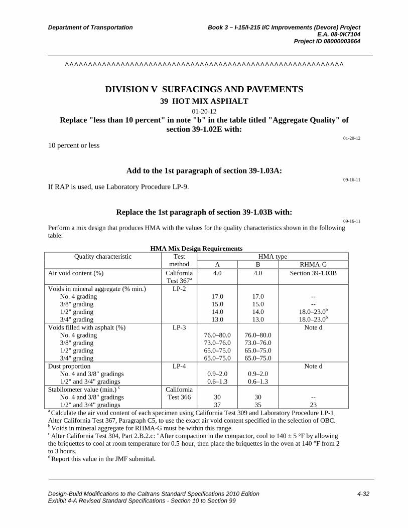
Department of Transportation Book 3 – I-15/I-215 I/C Improvements (Devore) Project E.A. 08-0K7104 Project ID 08000003664
Design-Build Modifications to the Caltrans Standard Specifications 2010 Edition 4-32 Exhibit 4-A Revised Standard Specifications - Section 10 to Section 99
^^^^^^^^^^^^^^^^^^^^^^^^^^^^^^^^^^^^^^^^^^^^^^^^^^^^^^^^^^^^
DIVISION V SURFACINGS AND PAVEMENTS 39 HOT MIX ASPHALT
01-20-12 Replace "less than 10 percent" in note "b" in the table titled "Aggregate Quality" of
section 39-1.02E with: 01-20-12
10 percent or less
Add to the 1st paragraph of section 39-1.03A: 09-16-11
If RAP is used, use Laboratory Procedure LP-9.
Replace the 1st paragraph of section 39-1.03B with: 09-16-11
Perform a mix design that produces HMA with the values for the quality characteristics shown in the following table:
HMA Mix Design Requirements Quality characteristic Test
method HMA type
A B RHMA-G Air void content (%) California
Test 367a 4.0 4.0 Section 39-1.03B
Voids in mineral aggregate (% min.) No. 4 grading 3/8" grading 1/2" grading 3/4" grading
LP-2 17.0 15.0 14.0 13.0
17.0 15.0 14.0 13.0
-- --
18.0–23.0b
18.0–23.0b Voids filled with asphalt (%)
No. 4 grading 3/8" grading 1/2" grading 3/4" grading
LP-3 76.0–80.0 73.0–76.0 65.0–75.0 65.0–75.0
76.0–80.0 73.0–76.0 65.0–75.0 65.0–75.0
Note d
Dust proportion No. 4 and 3/8" gradings 1/2" and 3/4" gradings
LP-4 0.9–2.0 0.6–1.3
0.9–2.0 0.6–1.3
Note d
Stabilometer value (min.) c No. 4 and 3/8" gradings 1/2" and 3/4" gradings
California Test 366
30 37
30 35
-- 23
a Calculate the air void content of each specimen using California Test 309 and Laboratory Procedure LP-1.
Alter California Test 367, Paragraph C5, to use the exact air void content specified in the selection of OBC. b Voids in mineral aggregate for RHMA-G must be within this range. c Alter California Test 304, Part 2.B.2.c: "After compaction in the compactor, cool to 140 ± 5 °F by allowing the briquettes to cool at room temperature for 0.5-hour, then place the briquettes in the oven at 140 °F from 2 to 3 hours. d Report this value in the JMF submittal.
Department of Transportation Book 3 – I-15/I-215 I/C Improvements (Devore) Project E.A. 08-0K7104 Project ID 08000003664
Design-Build Modifications to the Caltrans Standard Specifications 2010 Edition 4-33 Exhibit 4-A Revised Standard Specifications - Section 10 to Section 99
Replace item 4 in the list in the 1st paragraph of section 39-1.03C with: 01-20-12
4. JMF renewal on a Caltrans Job Mix Formula Renewal form, if applicable
Replace the 14th paragraph of section 39-1.03E with: 01-20-12
A verified JMF is valid for 12 months.
Replace the last sentence in the 15th paragraph of section 39-1.03E with: 01-20-12
This deduction does not apply to verifications initiated by the Engineer or JMF renewal.
01-20-12
Delete the 4th paragraph of section 39-1.03F.
Replace items 3 and 5 in the 6th paragraph of section 39-1.03F with: 01-20-12
3. Engineer verifies each proposed JMF renewal within 20 days of receiving verification samples. 5. For each HMA type and aggregate gradation specified, the Engineer verifies at the Department's expense 1
proposed JMF renewal within a 12-month period.
Add between the 6th and 7th paragraphs of section 39-1.03F: 01-20-12
The most recent aggregate quality test results within the past 12 months may be used for verification of JMF renewal or the Engineer may perform aggregate quality tests for verification of JMF renewal.
Replace section 39-1.03G with: 01-20-12
39-1.03G Job Mix Formula Modification For an accepted JMF, you may change binder source one time during production.
Submit your modified JMF request a minimum of 3 business days before production. Each modified JMF submittal must consist of:
1. Proposed modified JMF on Contractor Job Mix Formula Proposal form 2. Mix design records on Contractor Hot Mix Asphalt Design Data form for the accepted JMF to be modified 3. JMF verification on Hot Mix Asphalt Verification form for the accepted JMF to be modified 4. Quality characteristics test results for the modified JMF as specified in section 39-1.03B. Perform tests at the
mix design OBC as shown on the Contractor Asphalt Mix Design Data form 5. If required, California Test 371 test results for the modified JMF.
Department of Transportation Book 3 – I-15/I-215 I/C Improvements (Devore) Project E.A. 08-0K7104 Project ID 08000003664
Design-Build Modifications to the Caltrans Standard Specifications 2010 Edition 4-34 Exhibit 4-A Revised Standard Specifications - Section 10 to Section 99
With an accepted modified JMF submittal, the Engineer verifies each modified JMF within 5 business days of receiving all verification samples. If California Test 371 is required, the Engineer tests for California Test 371 within 10 days of receiving verification samples.
The Engineer verifies the modified JMF after the modified JMF HMA is placed on the project and verification samples are taken within the first 750 tons following sampling requirements in section 39-1.03E, "Job Mix Formula Verification." The Engineer tests verification samples for compliance with:
1. Stability as shown in the table titled "Hot Mix Asphalt Mix Design Requirements" 2. Air void content at design value ±2.0 percent 3. Voids in mineral aggregate as shown in the table titled "Hot Mix Asphalt Mix Design Requirements" 4. Voids filled with asphalt if an adjustment for asphalt binder content TV is more than ±0.3 percent from the
original OBC shown on the Contractor Asphalt Mix Design Data form. 5. Dust proportion if an adjustment for asphalt binder content TV is more than ±0.3 percent from OBC shown on
the Contractor Asphalt Mix Design Data form. If the modified JMF is verified, the Engineer revises your Hot Mix Asphalt Verification form to include the new binder source. Your revised form will have the same expiration date as the original form.
If a modified JMF is not verified, stop production and any HMA placed using the modified JMF is rejected.
The Engineer deducts $2,000 from payments for each modified JMF verification. The Engineer deducts an additional $2,000 for each modified JMF verification that requires California Test 371.
Add to section 39-1.03: 01-20-12
39-1.03H Job Mix Formula Acceptance You may start HMA production if:
1. The Engineer's review of the JMF shows compliance with the specifications. 2. The Department has verified the JMF within 12 months before HMA production. 3. The Engineer accepts the verified JMF.
Replace "3 days" in the 1st paragraph of section 39-1.04A with: 01-20-12
3 business days
Replace the 2nd sentence in the 2nd paragraph of section 39-1.04A with: 01-20-12
During production, take samples under California Test 125. You may sample HMA from:
Replace the 2nd paragraph of section 39-1.04E with: 09-16-11
Sample RAP once daily and determine the RAP aggregate gradation under Laboratory Procedure LP-9 and submit the results with the combined aggregate gradation.
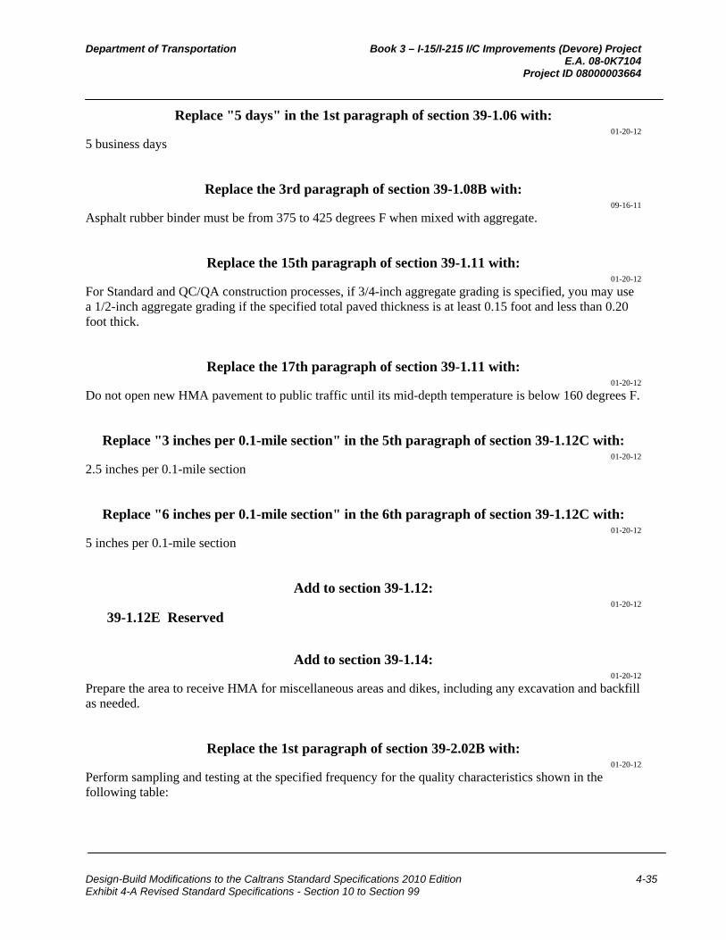
Department of Transportation Book 3 – I-15/I-215 I/C Improvements (Devore) Project E.A. 08-0K7104 Project ID 08000003664
Design-Build Modifications to the Caltrans Standard Specifications 2010 Edition 4-35 Exhibit 4-A Revised Standard Specifications - Section 10 to Section 99
Replace "5 days" in the 1st paragraph of section 39-1.06 with: 01-20-12
5 business days
Replace the 3rd paragraph of section 39-1.08B with: 09-16-11
Asphalt rubber binder must be from 375 to 425 degrees F when mixed with aggregate.
Replace the 15th paragraph of section 39-1.11 with: 01-20-12
For Standard and QC/QA construction processes, if 3/4-inch aggregate grading is specified, you may use a 1/2-inch aggregate grading if the specified total paved thickness is at least 0.15 foot and less than 0.20 foot thick.
Replace the 17th paragraph of section 39-1.11 with: 01-20-12
Do not open new HMA pavement to public traffic until its mid-depth temperature is below 160 degrees F.
Replace "3 inches per 0.1-mile section" in the 5th paragraph of section 39-1.12C with: 01-20-12
2.5 inches per 0.1-mile section
Replace "6 inches per 0.1-mile section" in the 6th paragraph of section 39-1.12C with: 01-20-12
5 inches per 0.1-mile section
Add to section 39-1.12: 01-20-12
39-1.12E Reserved
Add to section 39-1.14: 01-20-12
Prepare the area to receive HMA for miscellaneous areas and dikes, including any excavation and backfill as needed.
Replace the 1st paragraph of section 39-2.02B with: 01-20-12
Perform sampling and testing at the specified frequency for the quality characteristics shown in the following table:
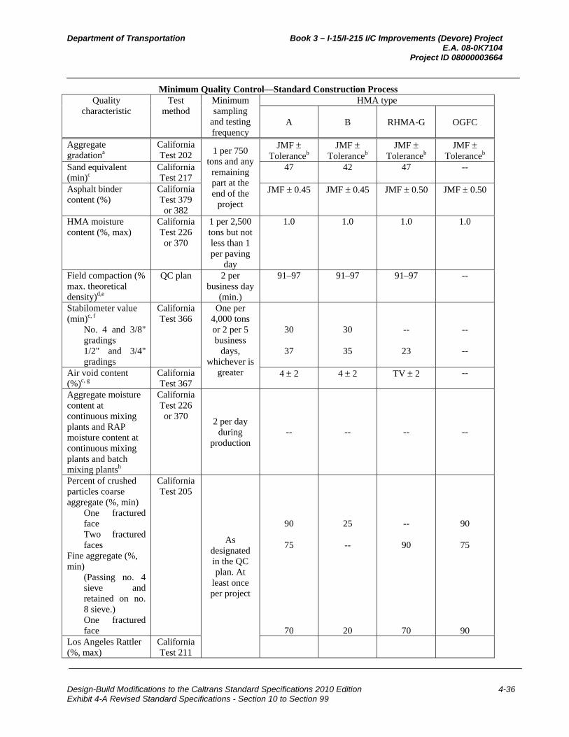
Department of Transportation Book 3 – I-15/I-215 I/C Improvements (Devore) Project E.A. 08-0K7104 Project ID 08000003664
Design-Build Modifications to the Caltrans Standard Specifications 2010 Edition 4-36 Exhibit 4-A Revised Standard Specifications - Section 10 to Section 99
Minimum Quality Control—Standard Construction Process Quality
characteristic Test
method Minimum sampling
and testing frequency
HMA type
A
B
RHMA-G
OGFC
Aggregate gradationa
California Test 202 1 per 750
tons and any remaining part at the end of the
project
JMF Toleranceb
JMF Toleranceb
JMF Toleranceb
JMF Toleranceb
Sand equivalent (min)c
California Test 217
47 42 47 --
Asphalt binder content (%)
California Test 379 or 382
JMF 0.45 JMF 0.45 JMF 0.50 JMF 0.50
HMA moisture content (%, max)
California Test 226 or 370
1 per 2,500 tons but not less than 1 per paving
day
1.0 1.0 1.0 1.0
Field compaction (% max. theoretical density)d,e
QC plan 2 per business day
(min.)
91–97 91–97 91–97 --
Stabilometer value (min)c, f
No. 4 and 3/8" gradings 1/2" and 3/4" gradings
California Test 366
One per 4,000 tons or 2 per 5 business
days, whichever is
greater
30
37
30
35
--
23
--
--
Air void content (%)c, g
California Test 367
4 2 4 2 TV 2 --
Aggregate moisture content at continuous mixing plants and RAP moisture content at continuous mixing plants and batch mixing plantsh
California Test 226 or 370
2 per day during
production -- -- -- --
Percent of crushed particles coarse aggregate (%, min)
One fractured face Two fractured faces
Fine aggregate (%, min)
(Passing no. 4 sieve and retained on no. 8 sieve.) One fractured face
California Test 205
As designated in the QC plan. At
least once per project
90
75
70
25
--
20
--
90
70
90
75
90 Los Angeles Rattler (%, max)
California Test 211

Department of Transportation Book 3 – I-15/I-215 I/C Improvements (Devore) Project E.A. 08-0K7104 Project ID 08000003664
Design-Build Modifications to the Caltrans Standard Specifications 2010 Edition 4-37 Exhibit 4-A Revised Standard Specifications - Section 10 to Section 99
Loss at 100 rev. Loss at 500 rev.
12
45
--
50
12
40
12
40 Flat and elongated particles (%, max by weight @ 5:1)
California Test 235
Report only Report only Report only Report only
Fine aggregate angularity (%, min)
California Test 234
45 45 45 --
Voids filled with asphalt (%)j
No. 4 grading 3/8" grading 1/2" grading 3/4" grading
LP-3
76.0–80.0 73.0–76.0 65.0–75.0 65.0–75.0
76.0–80.0 73.0–76.0 65.0–75.0 65.0–75.0
Report only --
Voids in mineral aggregate (% min)j
No. 4 grading 3/8" grading 1/2" grading 3/4" grading
LP-2
17.0 15.0 14.0 13.0
17.0 15.0 14.0 13.0
-- --
18.0–23.0 k
18.0–23.0 k
--
Dust proportion j No. 4 and 3/8" gradings 1/2" and 3/4" gradings
LP-4 0.9–2.0
0.6–1.3
0.9–2.0
0.6–1.3
Report only
--
Smoothness Section 39-1.12
--
12-foot straight-
edge, must grind, and
PI0
12-foot straight-
edge, must grind, and
PI0
12-foot straight-
edge, must grind, and
PI0
12-foot straight-
edge, must grind, and
PI0 Asphalt rubber binder viscosity @ 375 °F, centipoises
Section 39-1.02D
Section 39-1.04C -- -- 1,500–4,000 1,500–4,000
Asphalt modifier Section 39-1.02D
Section 39-1.04C
-- -- Section
39-1.02D Section
39-1.02D CRM Section
39-1.02D Section
39-1.04C -- -- Section
39-1.02D Section
39-1.02D a Determine combined aggregate gradation containing RAP under Laboratory Procedure LP-9. b The tolerances must comply with the allowable tolerances in section 39-1.02E. c Report the average of 3 tests from a single split sample.d Determine field compaction for any of the following conditions:
1. 1/2-inch, 3/8-inch, or no. 4 aggregate grading is used and the specified total paved thickness is at least 0.15 foot. 2. 3/4-inch aggregate grading is used and the specified total paved thickness is at least 0.20 foot.
e California Test 375 is used to determine field compaction, except use: 1. In-place density measurements using the method specified in your QC plan is used instead of using the nuclear gauge specified in Part 4 of California Test 375 2. California Test 309 to determine the maximum theoretical density instead of determining maximum density as specified in Part 5 of California Test 375
f Alter California Test 304, Part 2.B.2.c: "After compaction in the mechanical compactor, cool to 140 ± 5 °F by allowing the briquettes to cool at room temperature for 0.5 hour, then place the briquettes in the oven at 140 °F for a minimum of 2 hours and not more than 3 hours." g Determine the bulk specific gravity of each lab-compacted briquette under California Test 308, Method A, and

Department of Transportation Book 3 – I-15/I-215 I/C Improvements (Devore) Project E.A. 08-0K7104 Project ID 08000003664
Design-Build Modifications to the Caltrans Standard Specifications 2010 Edition 4-38 Exhibit 4-A Revised Standard Specifications - Section 10 to Section 99
theoretical maximum specific gravity under California Test 309. h For adjusting the plant controller at the HMA plant. i The Engineer waives this specification if HMA contains 10 percent or less of nonmanufactured sand by weight of total aggregate. Manufactured sand is fine aggregate produced by crushing rock or gravel. j Report only if the adjustment for the asphalt binder content TV is less than or equal to ±0.3 percent from OBC value submitted on a Contractor Hot Mix Asphalt Design Data form. k Voids in mineral aggregate for RHMA-G must be within this range.
Replace the 1st paragraph of section 39-2.03A with: 01-20-12
The Department samples for acceptance testing and tests for the quality characteristics shown in the following table:
HMA Acceptance—Standard Construction Process Quality characteristic Test
method HMA type
A B RHMA-G OGFC Aggregate gradation a California
Test 202 JMF
tolerance c JMF
tolerance c JMF
tolerance c JMF
tolerance c Sieve 3/4" 1/2" 3/8" 1/2" X b 3/8" X
No. 4 X No. 8 X X X
No. 200 X X X Sand equivalent (min) d California
Test 217 47 42 47 --
Asphalt binder content (%) California Test 379 or
382
JMF 0.45 JMF 0.45 JMF 0.50 JMF 0.50
HMA moisture content (%, max)
California Test 226 or
370
1.0 1.0 1.0 1.0
Field compaction (% max. theoretical density) e, f
California Test 375
91–97 91–97 91–97 --
Stabilometer value (min)d,g No. 4 and 3/8" gradings 1/2" and 3/4" gradings
California Test 366
30 37
30
35
-- 23
-- --
Air void content (%) d, h California Test 367
4 2 4 2 TV 2 --
Percent of crushed particles Coarse aggregate (%, min)
One fractured face Two fractured faces
Fine aggregate (%, min) (Passing no. 4 sieve and retained on no. 8 sieve.) One fractured face
California Test 205
90 75
70
25 --
20
-- 90
70
90 75
90 Los Angeles Rattler (%, max)
Loss at 100 rev. Loss at 500 rev.
California Test 211
12 45
-- 50
12 40
12 40
Fine aggregate angularity (%, min)i
California Test 234
45
45
45
--

Department of Transportation Book 3 – I-15/I-215 I/C Improvements (Devore) Project E.A. 08-0K7104 Project ID 08000003664
Design-Build Modifications to the Caltrans Standard Specifications 2010 Edition 4-39 Exhibit 4-A Revised Standard Specifications - Section 10 to Section 99
Flat and elongated particles (%, max by weight @ 5:1)
California Test 235
Report only Report only Report only Report only
Voids filled with asphalt (%) j No. 4 grading 3/8" grading 1/2" grading 3/4" grading
LP-3 76.0–80.0 73.0–76.0 65.0–75.0 65.0–75.0
76.0–80.0 73.0–76.0 65.0–75.0 65.0–75.0
Report only --
Voids in mineral aggregate (% min) j
No. 4 grading 3/8" grading 1/2" grading 3/4" grading
LP-2
17.0 15.0 14.0 13.0
17.0 15.0 14.0 13.0
-- --
18.0–23.0 k
18.0–23.0 k
--
Dust proportion j No. 4 and 3/8" gradings 1/2" and 3/4" gradings
LP-4 0.9–2.0 0.6–1.3
0.9–2.0 0.6–1.3
Report only --
Smoothness Section 39-1.12
12-foot straight-
edge, must grind, and
PI0
12-foot straight-
edge, must grind, and
PI0
12-foot straight-
edge, must grind, and
PI0
12-foot straight-edge
and must grind
Asphalt binder Various Section 92 Section 92 Section 92 Section 92 Asphalt rubber binder Various -- -- Section
92-1.01D(2) and section 39-1.02D
Section 92-1.01D(2) and section 39-1.02D
Asphalt modifier Various -- -- Section 39-1.02D
Section 39-1.02D
CRM Various -- -- Section 39-1.02D
Section 39-1.02D
a The Engineer determines combined aggregate gradations containing RAP under Laboratory Procedure LP-9. b "X" denotes the sieves the Engineer tests for the specified aggregate gradation. c The tolerances must comply with the allowable tolerances in section 39-1.02E. d The Engineer reports the average of 3 tests from a single split sample. e The Engineer determines field compaction for any of the following conditions:
1. 1/2-inch, 3/8-inch, or no. 4 aggregate grading is used and the specified total paved thickness is at least 0.15 foot. 2. 3/4-inch aggregate grading is used and the specified total paved thickness is at least 0.20 foot.
f California Test 375 is used to determine field compaction, except the Engineer uses: 1. California Test 375, Method A, to determine in-place density measurements instead of using the nuclear gauge specified in Part 4 of California Test 375 2. California Test 309 is used to determine the maximum theoretical density instead of determining maximum density as specified in Part 5 of California Test 375
g Alter California Test 304, Part 2.B.2.c: "After compaction in the mechanical compactor, cool to 140 ±5 °F by allowing the briquettes to cool at room temperature for 0.5 hour, then place the briquettes in the oven at 140 °F from 2 to 3 hours." h The Engineer determines the bulk specific gravity of each lab-compacted briquette under California Test 308, Method A, and theoretical maximum specific gravity under California Test 309. i The Engineer waives this specification if HMA contains 10 percent or less of nonmanufactured sand by weight of total aggregate. Manufactured sand is fine aggregate produced by crushing rock or gravel. j Report only if the adjustment for the asphalt binder content TV is less than or equal to ±0.3 percent from the OBC value submitted on a Contractor Hot Mix Asphalt Design Data form. k Voids in mineral aggregate for RHMA-G must be within this range.
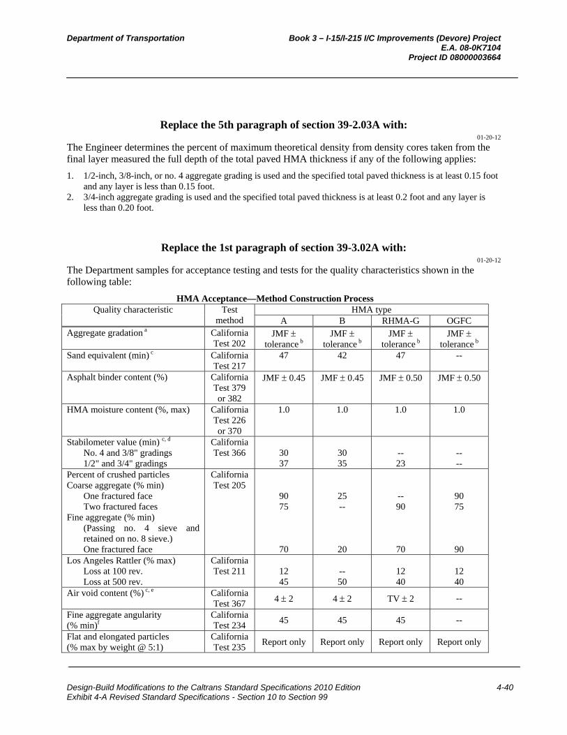
Department of Transportation Book 3 – I-15/I-215 I/C Improvements (Devore) Project E.A. 08-0K7104 Project ID 08000003664
Design-Build Modifications to the Caltrans Standard Specifications 2010 Edition 4-40 Exhibit 4-A Revised Standard Specifications - Section 10 to Section 99
Replace the 5th paragraph of section 39-2.03A with: 01-20-12
The Engineer determines the percent of maximum theoretical density from density cores taken from the final layer measured the full depth of the total paved HMA thickness if any of the following applies:
1. 1/2-inch, 3/8-inch, or no. 4 aggregate grading is used and the specified total paved thickness is at least 0.15 foot and any layer is less than 0.15 foot.
2. 3/4-inch aggregate grading is used and the specified total paved thickness is at least 0.2 foot and any layer is less than 0.20 foot.
Replace the 1st paragraph of section 39-3.02A with: 01-20-12
The Department samples for acceptance testing and tests for the quality characteristics shown in the following table:
HMA Acceptance—Method Construction Process Quality characteristic Test
method HMA type
A B RHMA-G OGFC Aggregate gradation a California
Test 202 JMF
tolerance b JMF
tolerance b JMF
tolerance b JMF
tolerance b Sand equivalent (min) c California
Test 217 47 42 47 --
Asphalt binder content (%) California Test 379 or 382
JMF 0.45 JMF 0.45 JMF 0.50 JMF 0.50
HMA moisture content (%, max) California Test 226 or 370
1.0 1.0 1.0 1.0
Stabilometer value (min) c, d No. 4 and 3/8" gradings 1/2" and 3/4" gradings
California Test 366
30 37
30 35
-- 23
-- --
Percent of crushed particles Coarse aggregate (% min)
One fractured face Two fractured faces
Fine aggregate (% min) (Passing no. 4 sieve and retained on no. 8 sieve.) One fractured face
California Test 205
90 75
70
25 --
20
-- 90
70
90 75
90 Los Angeles Rattler (% max)
Loss at 100 rev. Loss at 500 rev.
California Test 211
12 45
-- 50
12 40
12 40
Air void content (%) c, e California Test 367 4 2 4 2 TV 2 --
Fine aggregate angularity (% min)f
California Test 234
45 45 45 --
Flat and elongated particles (% max by weight @ 5:1)
California Test 235
Report only Report only Report only Report only
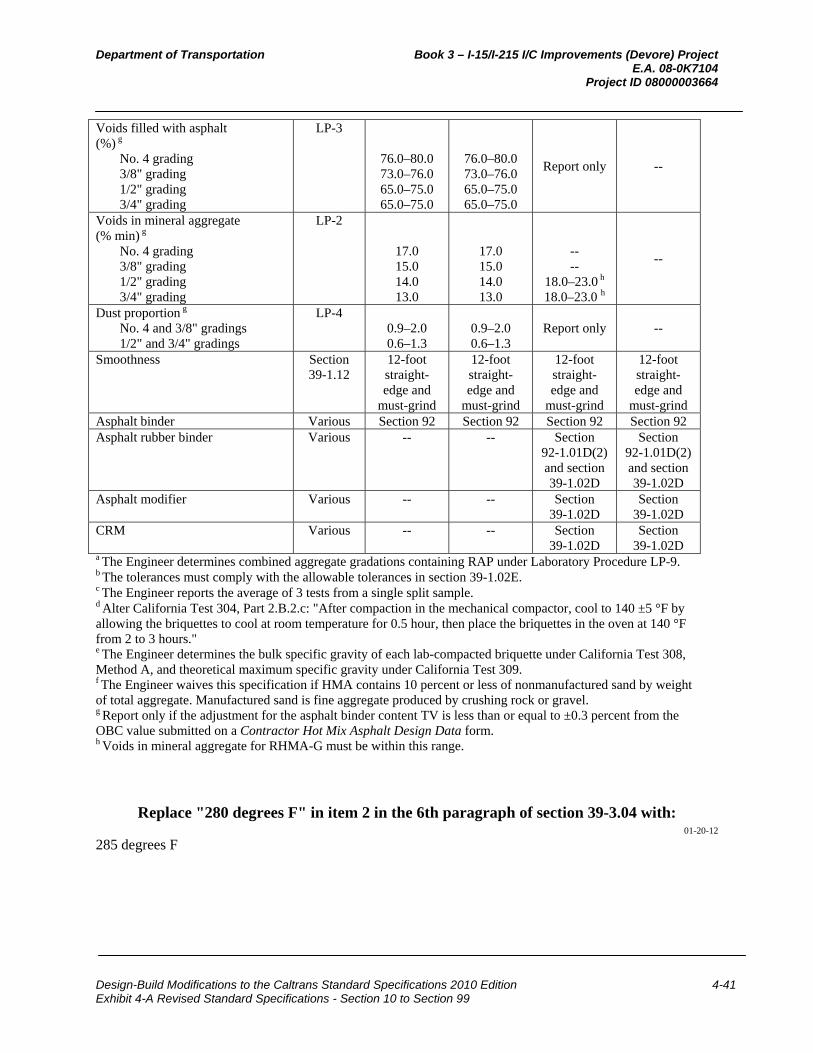
Department of Transportation Book 3 – I-15/I-215 I/C Improvements (Devore) Project E.A. 08-0K7104 Project ID 08000003664
Design-Build Modifications to the Caltrans Standard Specifications 2010 Edition 4-41 Exhibit 4-A Revised Standard Specifications - Section 10 to Section 99
Voids filled with asphalt (%) g
No. 4 grading 3/8" grading 1/2" grading 3/4" grading
LP-3
76.0–80.0 73.0–76.0 65.0–75.0 65.0–75.0
76.0–80.0 73.0–76.0 65.0–75.0 65.0–75.0
Report only --
Voids in mineral aggregate (% min) g
No. 4 grading 3/8" grading 1/2" grading 3/4" grading
LP-2
17.0 15.0 14.0 13.0
17.0 15.0 14.0 13.0
-- --
18.0–23.0 h
18.0–23.0 h
--
Dust proportion g No. 4 and 3/8" gradings 1/2" and 3/4" gradings
LP-4 0.9–2.0 0.6–1.3
0.9–2.0 0.6–1.3
Report only --
Smoothness Section 39-1.12
12-foot straight-edge and
must-grind
12-foot straight-edge and
must-grind
12-foot straight-edge and
must-grind
12-foot straight-edge and
must-grind Asphalt binder Various Section 92 Section 92 Section 92 Section 92 Asphalt rubber binder Various -- -- Section
92-1.01D(2) and section 39-1.02D
Section 92-1.01D(2) and section 39-1.02D
Asphalt modifier Various -- -- Section 39-1.02D
Section 39-1.02D
CRM Various -- -- Section 39-1.02D
Section 39-1.02D
a The Engineer determines combined aggregate gradations containing RAP under Laboratory Procedure LP-9. b The tolerances must comply with the allowable tolerances in section 39-1.02E. c The Engineer reports the average of 3 tests from a single split sample. d Alter California Test 304, Part 2.B.2.c: "After compaction in the mechanical compactor, cool to 140 ±5 °F by allowing the briquettes to cool at room temperature for 0.5 hour, then place the briquettes in the oven at 140 °F from 2 to 3 hours." e The Engineer determines the bulk specific gravity of each lab-compacted briquette under California Test 308, Method A, and theoretical maximum specific gravity under California Test 309. f The Engineer waives this specification if HMA contains 10 percent or less of nonmanufactured sand by weight of total aggregate. Manufactured sand is fine aggregate produced by crushing rock or gravel. g Report only if the adjustment for the asphalt binder content TV is less than or equal to ±0.3 percent from the OBC value submitted on a Contractor Hot Mix Asphalt Design Data form. h Voids in mineral aggregate for RHMA-G must be within this range.
Replace "280 degrees F" in item 2 in the 6th paragraph of section 39-3.04 with: 01-20-12
285 degrees F

Department of Transportation Book 3 – I-15/I-215 I/C Improvements (Devore) Project E.A. 08-0K7104 Project ID 08000003664
Design-Build Modifications to the Caltrans Standard Specifications 2010 Edition 4-42 Exhibit 4-A Revised Standard Specifications - Section 10 to Section 99
Replace the 8th paragraph of section 39-4.02C with: 01-20-12
Comply with the values for the HMA quality characteristics and minimum random sampling and testing for quality control shown in the following table:
Minimum Quality Control—QC/QA Construction Process Quality
characteristic Test
method Minimum sampling
and testing frequency
HMA Type
Location of
sampling
Maxi-mum
report-ing time
allow-ance
A B RHMA-G
Aggregate gradationa
California Test 202
1 per 750 tons
JMF ± tolerance b
JMF ± tolerance b
JMF ± tolerance b
California Test 125
24 hours
Asphalt binder content (%)
California Test 379 or 382
JMF ±0.45 JMF ±0.45 JMF ±0.50
Loose mix behind paver See
California Test 125
Field compaction (% max. theoretical density)c,d
QC plan 92–96 92–96 91–96 QC plan
Aggregate moisture content at continuous mixing plants and RAP moisture content at continuous mixing plants and batch mixing plantse
California Test 226 or 370
2 per day during
production -- -- --
Stock-piles or
cold feed belts
--
Sand equivalent (min) f
California Test 217
1 per 750 tons
47 42 47 California Test 125
24 hours
HMA moisture content (%,max)
California Test 226 or 370
1 per 2,500 tons but not less
than 1 per paving day
1.0 1.0 1.0
Loose Mix
Behind Paver See
California Test 125
24 hours
Stabilometer value (min)f,g
No. 4 and 3/8" gradings 1/2" and 3/4" gradings
California Test 366
1 per 4,000 tons or 2
per 5 business
days, whichever is greater
30
37
30
35
--
23
48 hours
Air void content (%)f,h
California Test 367
4 ± 2 4 ± 2 TV ± 2
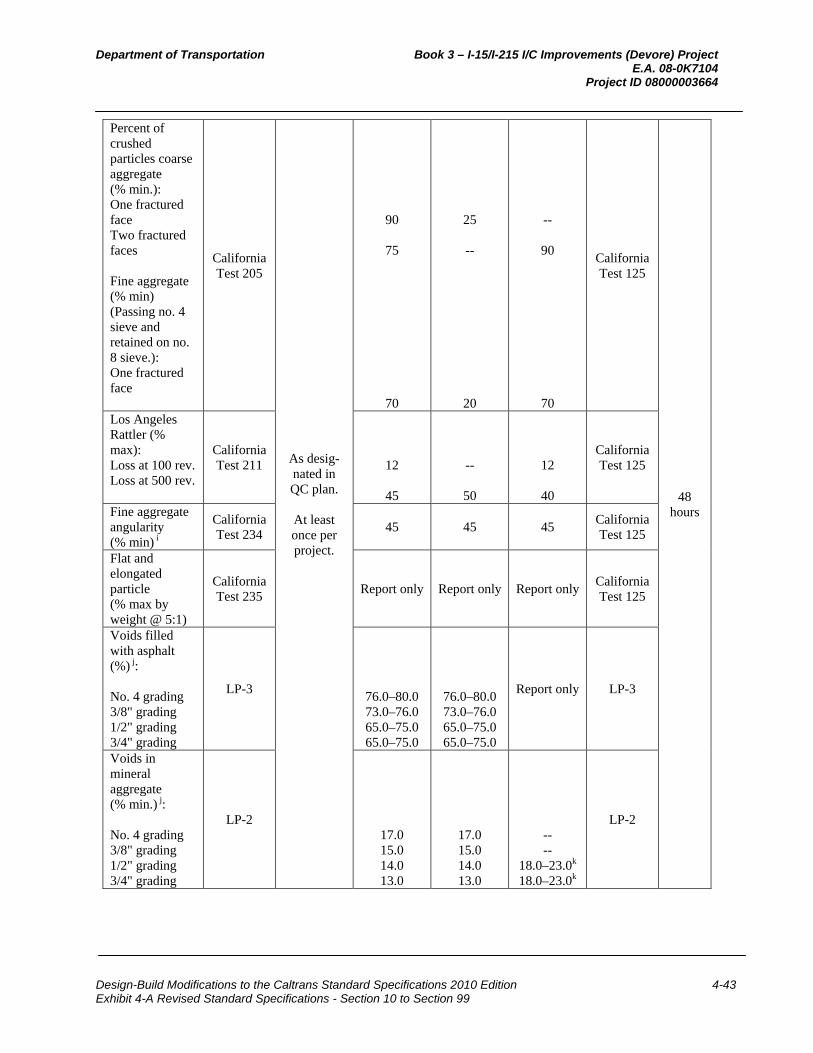
Department of Transportation Book 3 – I-15/I-215 I/C Improvements (Devore) Project E.A. 08-0K7104 Project ID 08000003664
Design-Build Modifications to the Caltrans Standard Specifications 2010 Edition 4-43 Exhibit 4-A Revised Standard Specifications - Section 10 to Section 99
Percent of crushed particles coarse aggregate (% min.): One fractured face Two fractured faces Fine aggregate (% min) (Passing no. 4 sieve and retained on no. 8 sieve.): One fractured face
California Test 205
As desig-nated in QC plan.
At least once per project.
90
75
70
25
--
20
--
90
70
California Test 125
48 hours
Los Angeles Rattler (% max): Loss at 100 rev. Loss at 500 rev.
California Test 211
12
45
--
50
12
40
California Test 125
Fine aggregate angularity (% min) i
California Test 234
45 45 45 California Test 125
Flat and elongated particle (% max by weight @ 5:1)
California Test 235
Report only Report only Report only California Test 125
Voids filled with asphalt (%) j:
No. 4 grading 3/8" grading 1/2" grading 3/4" grading
LP-3
76.0–80.0 73.0–76.0 65.0–75.0 65.0–75.0
76.0–80.0 73.0–76.0 65.0–75.0 65.0–75.0
Report only LP-3
Voids in mineral aggregate (% min.) j:
No. 4 grading 3/8" grading 1/2" grading 3/4" grading
LP-2
17.0 15.0 14.0 13.0
17.0 15.0 14.0 13.0
-- --
18.0–23.0k
18.0–23.0k
LP-2
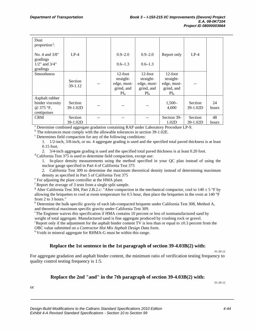
Department of Transportation Book 3 – I-15/I-215 I/C Improvements (Devore) Project E.A. 08-0K7104 Project ID 08000003664
Design-Build Modifications to the Caltrans Standard Specifications 2010 Edition 4-44 Exhibit 4-A Revised Standard Specifications - Section 10 to Section 99
Dust proportion j: No. 4 and 3/8" gradings 1/2" and 3/4" gradings
LP-4
0.9–2.0
0.6–1.3
0.9–2.0
0.6–1.3
Report only LP-4
Smoothness
Section 39-1.12
--
12-foot straight-
edge, must-grind, and
PI0
12-foot straight-
edge, must-grind, and
PI0
12-foot straight-
edge, must-grind, and
PI0
--
Asphalt rubber binder viscosity @ 375 °F, centipoises
Section 39-1.02D
-- -- -- 1,500–4,000
Section 39-1.02D
24 hours
CRM Section 39-1.02D
-- -- -- Section 39-1.02D
Section 39-1.02D
48 hours
a Determine combined aggregate gradation containing RAP under Laboratory Procedure LP-9. b The tolerances must comply with the allowable tolerances in section 39-1.02E. c Determines field compaction for any of the following conditions:
1. 1/2-inch, 3/8-inch, or no. 4 aggregate grading is used and the specified total paved thickness is at least 0.15 foot. 2. 3/4-inch aggregate grading is used and the specified total paved thickness is at least 0.20 foot.
d California Test 375 is used to determine field compaction, except use: 1. In-place density measurements using the method specified in your QC plan instead of using the nuclear gauge specified in Part 4 of California Test 375 2. California Test 309 to determine the maximum theoretical density instead of determining maximum density as specified in Part 5 of California Test 375
e For adjusting the plant controller at the HMA plant. f Report the average of 3 tests from a single split sample. g Alter California Test 304, Part 2.B.2.c: "After compaction in the mechanical compactor, cool to 140 ± 5 °F by allowing the briquettes to cool at room temperature for 0.5 hour, then place the briquettes in the oven at 140 °F from 2 to 3 hours." h Determine the bulk specific gravity of each lab-compacted briquette under California Test 308, Method A, and theoretical maximum specific gravity under California Test 309. i The Engineer waives this specification if HMA contains 10 percent or less of nonmanufactured sand by weight of total aggregate. Manufactured sand is fine aggregate produced by crushing rock or gravel. j Report only if the adjustment for the asphalt binder content TV is less than or equal to ±0.3 percent from the OBC value submitted on a Contractor Hot Mix Asphalt Design Data form. k Voids in mineral aggregate for RHMA-G must be within this range.
Replace the 1st sentence in the 1st paragraph of section 39-4.03B(2) with: 01-20-12
For aggregate gradation and asphalt binder content, the minimum ratio of verification testing frequency to quality control testing frequency is 1:5.
Replace the 2nd "and" in the 7th paragraph of section 39-4.03B(2) with: 01-20-12
or
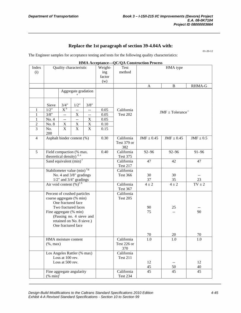
Department of Transportation Book 3 – I-15/I-215 I/C Improvements (Devore) Project E.A. 08-0K7104 Project ID 08000003664
Design-Build Modifications to the Caltrans Standard Specifications 2010 Edition 4-45 Exhibit 4-A Revised Standard Specifications - Section 10 to Section 99
Replace the 1st paragraph of section 39-4.04A with: 01-20-12
The Engineer samples for acceptance testing and tests for the following quality characteristics:
HMA Acceptance—QC/QA Construction ProcessIndex
(i) Quality characteristic Weight-
ing factor (w)
Test method
HMA type
A B RHMA-G Aggregate gradation
a
California Test 202
JMF ± Tolerance c
Sieve
3/4" 1/2" 3/8"
1 1/2" X b -- -- 0.05 1 3/8" -- X -- 0.05 1 No. 4 -- -- X 0.05 2 No. 8 X X X 0.10 3 No.
200 X X X 0.15
4 Asphalt binder content (%) 0.30 California Test 379 or
382
JMF ± 0.45 JMF ± 0.45 JMF ± 0.5
5 Field compaction (% max. theoretical density) d, e
0.40 California Test 375
92–96 92–96 91–96
Sand equivalent (min) f California Test 217
47 42 47
Stabilometer value (min) f,g No. 4 and 3/8" gradings 1/2" and 3/4" gradings
California Test 366
30 37
30 35
-- 23
Air void content (%)f, h California Test 367
4 ± 2 4 ± 2 TV ± 2
Percent of crushed particles coarse aggregate (% min)
One fractured face Two fractured faces
Fine aggregate (% min) (Passing no. 4 sieve and retained on No. 8 sieve.) One fractured face
California Test 205
90 75
70
25 --
20
-- 90
70
HMA moisture content (%, max)
California Test 226 or
370
1.0 1.0 1.0
Los Angeles Rattler (% max) Loss at 100 rev. Loss at 500 rev.
California Test 211
12 45
-- 50
12 40
Fine aggregate angularity (% min)i
California Test 234
45 45 45
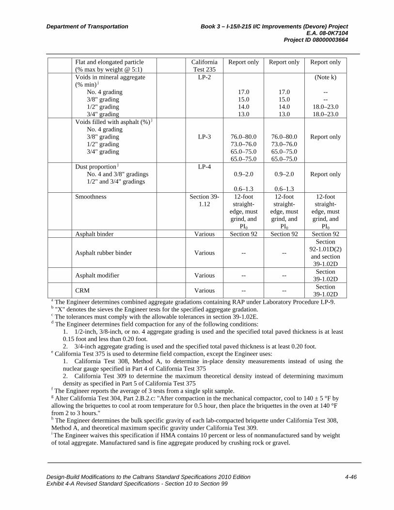
Department of Transportation Book 3 – I-15/I-215 I/C Improvements (Devore) Project E.A. 08-0K7104 Project ID 08000003664
Design-Build Modifications to the Caltrans Standard Specifications 2010 Edition 4-46 Exhibit 4-A Revised Standard Specifications - Section 10 to Section 99
Flat and elongated particle (% max by weight @ 5:1)
California Test 235
Report only Report only Report only
Voids in mineral aggregate (% min) j
No. 4 grading 3/8" grading 1/2" grading 3/4" grading
LP-2
17.0 15.0 14.0 13.0
17.0 15.0 14.0 13.0
(Note k)
-- --
18.0–23.0
18.0–23.0 Voids filled with asphalt (%) j
No. 4 grading 3/8" grading 1/2" grading 3/4" grading
LP-3
76.0–80.0 73.0–76.0 65.0–75.0 65.0–75.0
76.0–80.0 73.0–76.0 65.0–75.0 65.0–75.0
Report only
Dust proportion j No. 4 and 3/8" gradings 1/2" and 3/4" gradings
LP-4 0.9–2.0
0.6–1.3
0.9–2.0
0.6–1.3
Report only
Smoothness Section 39-1.12
12-foot straight-
edge, must grind, and
PI0
12-foot straight-
edge, must grind, and
PI0
12-foot straight-
edge, must grind, and
PI0 Asphalt binder Various Section 92 Section 92 Section 92
Asphalt rubber binder Various -- --
Section 92-1.01D(2) and section 39-1.02D
Asphalt modifier Various -- --
Section 39-1.02D
CRM Various -- --
Section 39-1.02D
a The Engineer determines combined aggregate gradations containing RAP under Laboratory Procedure LP-9. b "X" denotes the sieves the Engineer tests for the specified aggregate gradation. c The tolerances must comply with the allowable tolerances in section 39-1.02E. d The Engineer determines field compaction for any of the following conditions:
1. 1/2-inch, 3/8-inch, or no. 4 aggregate grading is used and the specified total paved thickness is at least 0.15 foot and less than 0.20 foot. 2. 3/4-inch aggregate grading is used and the specified total paved thickness is at least 0.20 foot.
e California Test 375 is used to determine field compaction, except the Engineer uses: 1. California Test 308, Method A, to determine in-place density measurements instead of using the nuclear gauge specified in Part 4 of California Test 375 2. California Test 309 to determine the maximum theoretical density instead of determining maximum density as specified in Part 5 of California Test 375
f The Engineer reports the average of 3 tests from a single split sample. g Alter California Test 304, Part 2.B.2.c: "After compaction in the mechanical compactor, cool to 140 ± 5 °F by allowing the briquettes to cool at room temperature for 0.5 hour, then place the briquettes in the oven at 140 °F from 2 to 3 hours." h The Engineer determines the bulk specific gravity of each lab-compacted briquette under California Test 308, Method A, and theoretical maximum specific gravity under California Test 309. i The Engineer waives this specification if HMA contains 10 percent or less of nonmanufactured sand by weight of total aggregate. Manufactured sand is fine aggregate produced by crushing rock or gravel.

Department of Transportation Book 3 – I-15/I-215 I/C Improvements (Devore) Project E.A. 08-0K7104 Project ID 08000003664
Design-Build Modifications to the Caltrans Standard Specifications 2010 Edition 4-47 Exhibit 4-A Revised Standard Specifications - Section 10 to Section 99
j Report only if the adjustment for the asphalt binder content TV is less than or equal to ±0.3 percent from the OBC value submitted on a Contractor Hot Mix Asphalt Design Data form. k Voids in mineral aggregate for RHMA-G must be within this range.
Replace the 3rd paragraph of section 39-4.04A with: 01-20-12
The Department determines the percent of maximum theoretical density from density cores taken from the final layer measured the full depth of the total paved HMA thickness if any of the following applies:
1. 1/2-inch, 3/8-inch, or no. 4 aggregate grading is used and the specified total paved thickness is at least 0.15 foot and any lager is less than 0.15 foot.
2. 3/4-inch aggregate grading is used and the specified total paved thickness is at least 0.20 and any layer is less than 0.20 foot.
^^^^^^^^^^^^^^^^^^^^^^^^^^^^^^^^^^^^^^^^
40 CONCRETE PAVEMENT 01-20-12
Replace section 40-1.01C(4) with: 01-20-12
40-1.01C(4) Authorized Laboratory Submit for authorization the name of the laboratory you propose to use for testing the drilled core specimens for air content.
Replace the paragraph in section 40-1.01C(8) with: 01-20-12
Submit a plan for protecting concrete pavement during the initial 72 hours after paving when the forecasted minimum ambient temperature is below 40 degrees F.
01-20-12
Delete "determined under California Test 559" in section 40-1.01C(9).
Replace the 2nd and 3rd paragraphs in section 40-1.01D(4) with: 01-20-12
The QC plan must include details of corrective action to be taken if any process is out of control. As a minimum, a process is out of control if any of the following occurs:
1. For fine and coarse aggregate gradation, 2 consecutive running averages of 4 tests are outside the specification limits
2. For individual penetration or air content measurements: 2.1. One point falls outside the suspension limit line 2.2. Two points in a row fall outside the action limit line
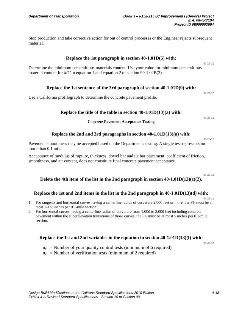
Department of Transportation Book 3 – I-15/I-215 I/C Improvements (Devore) Project E.A. 08-0K7104 Project ID 08000003664
Design-Build Modifications to the Caltrans Standard Specifications 2010 Edition 4-48 Exhibit 4-A Revised Standard Specifications - Section 10 to Section 99
Stop production and take corrective action for out of control processes or the Engineer rejects subsequent material.
Replace the 1st paragraph in section 40-1.01D(5) with: 01-20-12
Determine the minimum cementitious materials content. Use your value for minimum cementitious material content for MC in equation 1 and equation 2 of section 90-1.02B(3).
Replace the 1st sentence of the 3rd paragraph of section 40-1.01D(9) with: 01-20-12
Use a California profilograph to determine the concrete pavement profile.
Replace the title of the table in section 40-1.01D(13)(a) with: 01-20-12
Concrete Pavement Acceptance Testing
Replace the 2nd and 3rd paragraphs in section 40-1.01D(13)(a) with: 01-20-12
Pavement smoothness may be accepted based on the Department's testing. A single test represents no more than 0.1 mile.
Acceptance of modulus of rupture, thickness, dowel bar and tie bar placement, coefficient of friction, smoothness, and air content, does not constitute final concrete pavement acceptance.
01-20-12
Delete the 4th item of the list in the 2nd paragraph in section 40-1.01D(13)(c)(2).
Replace the 1st and 2nd items in the list in the 2nd paragraph in 40-1.01D(13)(d) with: 01-20-12
1. For tangents and horizontal curves having a centerline radius of curvature 2,000 feet or more, the PI0 must be at most 2-1/2 inches per 0.1-mile section.
2. For horizontal curves having a centerline radius of curvature from 1,000 to 2,000 feet including concrete pavement within the superelevation transitions of those curves, the PI0 must be at most 5 inches per 0.1-mile section.
Replace the 1st and 2nd variables in the equation in section 40-1.01D(13)(f) with: 01-20-12
nc = Number of your quality control tests (minimum of 6 required) nv = Number of verification tests (minimum of 2 required)

Department of Transportation Book 3 – I-15/I-215 I/C Improvements (Devore) Project E.A. 08-0K7104 Project ID 08000003664
Design-Build Modifications to the Caltrans Standard Specifications 2010 Edition 4-49 Exhibit 4-A Revised Standard Specifications - Section 10 to Section 99
Replace "Your approved third party independent testing laboratory" in the 4th paragraph of section 40-1.01D(13)(f) with:
01-20-12
The authorized laboratory
Replace the 2nd item in the 2nd paragraph of section 40-1.01D(13)(g): 01-20-12
2. One test for every 4,000 square yards of concrete pavement with tie bars or remaining fraction of that area. Each tie bar test consists of 2 cores with 1 on each tie-bar-end to expose both ends and allow measurement.
Replace section 40-1.01D(13)(h) with: 01-20-12
40-1.01D(13)(h) Bar Reinforcement
Bar reinforcement is accepted based on inspection before concrete placement.
Replace the paragraph in section 40-1.02B(2) with: 01-20-12
PCC for concrete pavement must comply with section 90-1 except as otherwise specified.
Replace the paragraphs in section 40-1.02D with: 01-20-12
Bar reinforcement must be deformed bars.
If the project is not shown to be in high desert or any mountain climate region, bar reinforcement must comply with section 52.
If the project is shown to be in high desert or any mountain climate regions, bar reinforcement must be one of the following:
1. Epoxy-coated bar reinforcement under section 52-2.03B except bars must comply with either ASTM A 706/A 706M; ASTM A 996/A 996M; or ASTM A 615/A 615M, Grade 40 or 60. Bars must be handled under ASTM D 3963/D 3963M and section 52-2.02C.
2. Low carbon, chromium steel bar complying with ASTM A 1035/A 1035M
Replace the paragraphs in section 40-1.02E with: 01-20-12
Tie bars must be deformed bars.
If the project is not shown to be in high desert or any mountain climate region, tie bars must be one of the following:
1. Epoxy-coated bar reinforcement. Bars must comply with either section 52-2.02B or 52-2.03B except bars must comply with either ASTM A 706/A 706M; ASTM A 996/A 996M; or ASTM A 615/A 615M, Grade 40 or 60.
2. Stainless-steel bars. Bars must be descaled, pickled, polished, and solid stainless-steel bars under ASTM A 955/A 955M, Grade 60, UNS Designation S31603 or S31803.
3. Low carbon, chromium-steel bars under ASTM A 1035/A 1035M.

Department of Transportation Book 3 – I-15/I-215 I/C Improvements (Devore) Project E.A. 08-0K7104 Project ID 08000003664
Design-Build Modifications to the Caltrans Standard Specifications 2010 Edition 4-50 Exhibit 4-A Revised Standard Specifications - Section 10 to Section 99
If the project is shown to be in high desert or any mountain climate region, tie bars must be one of the following:
1. Epoxy-coated bar reinforcement. Bars must comply with section 52-2.03B except bars must comply with either ASTM A 706/A 706M; ASTM A 996/A 996M; or ASTM A 615/A 615M, Grade 40 or 60.
2. Stainless-steel bars. Bars must be descaled, pickled, polished, and solid stainless-steel bars under ASTM A 955/A 955M, Grade 60, UNS Designation S31603 or S31803.
Fabricate, sample, and handle epoxy-coated tie bars under ASTM D 3963/D 3963M, section 52-2.02C, or section 52-2.03C.
Do not bend tie bars.
Replace the 1st, 2nd, and 3rd paragraphs in section 40-1.02F with: 01-20-12
Dowel bars must be plain bars. Fabricate, sample, and handle epoxy-coated dowel bars under ASTM D 3963/D 3963M and section 52-2.03C except each sample must be 18 inches long.
If the project is not shown to be in high desert or any mountain climate region, dowel bars must be one of the following:
1. Epoxy-coated bars. Bars must comply with ASTM A 615/A 615M, Grade 40 or 60. Epoxy coating must comply with either section 52-2.02B or 52-2.03B.
2. Stainless-steel bars. Bars must be descaled, pickled, polished, and solid stainless-steel bars under ASTM A 955/A 955M, Grade 60, UNS Designation S31603 or S31803.
3. Low carbon, chromium-steel bars under ASTM A 1035/A 1035M. If the project is shown to be in high desert or any mountain climate region, dowel bars must be one of the following:
1. Epoxy-coated bars. Bars must comply with ASTM A 615/A 615M, Grade 40 or 60. Epoxy coating must comply with section 52-2.03B.
2. Stainless-steel bars. Bars must be descaled, pickled, polished, and solid stainless-steel bars under ASTM A 955/A 955M, Grade 60, UNS Designation S31603 or S31803.
Replace the paragraphs in section 40-1.02G with: 01-20-12
For dowel and tie bar baskets, wire must comply with ASTM A 82/A 82M and be welded under ASTM A 185/A 185M, Section 7.4. The minimum wire-size no. is W10. Use either U-frame or A-frame shaped assemblies.
If the project is not shown to be in high desert or any mountain climate region. Baskets may be epoxy-coated, and the epoxy coating must comply with either section 52-2.02B or 52-2.03B.
If the project is shown to be in high desert or any mountain climate region, wire for dowel bar and tie bar baskets must be one of the following:
1. Epoxy-coated wire complying with section 52-2.03B 2. Stainless-steel wire. Wire must be descaled, pickled, and polished solid stainless-steel. Wire must comply with
(1) the chemical requirements in ASTM A 276/A 276M, UNS Designation S31603 or S31803 and (2) the tension requirements in ASTM A 1022/ A 1022M.
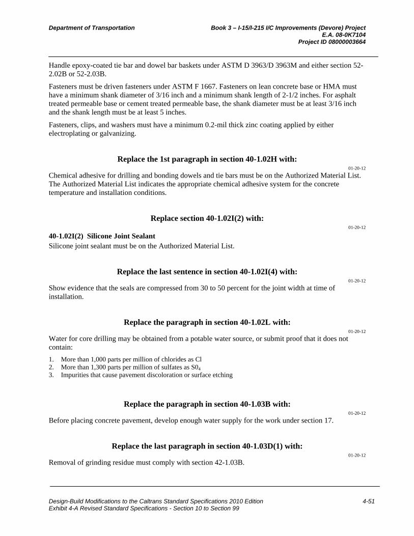
Department of Transportation Book 3 – I-15/I-215 I/C Improvements (Devore) Project E.A. 08-0K7104 Project ID 08000003664
Design-Build Modifications to the Caltrans Standard Specifications 2010 Edition 4-51 Exhibit 4-A Revised Standard Specifications - Section 10 to Section 99
Handle epoxy-coated tie bar and dowel bar baskets under ASTM D 3963/D 3963M and either section 52-2.02B or 52-2.03B.
Fasteners must be driven fasteners under ASTM F 1667. Fasteners on lean concrete base or HMA must have a minimum shank diameter of 3/16 inch and a minimum shank length of 2-1/2 inches. For asphalt treated permeable base or cement treated permeable base, the shank diameter must be at least 3/16 inch and the shank length must be at least 5 inches.
Fasteners, clips, and washers must have a minimum 0.2-mil thick zinc coating applied by either electroplating or galvanizing.
Replace the 1st paragraph in section 40-1.02H with: 01-20-12
Chemical adhesive for drilling and bonding dowels and tie bars must be on the Authorized Material List. The Authorized Material List indicates the appropriate chemical adhesive system for the concrete temperature and installation conditions.
Replace section 40-1.02I(2) with: 01-20-12
40-1.02I(2) Silicone Joint Sealant Silicone joint sealant must be on the Authorized Material List.
Replace the last sentence in section 40-1.02I(4) with: 01-20-12
Show evidence that the seals are compressed from 30 to 50 percent for the joint width at time of installation.
Replace the paragraph in section 40-1.02L with: 01-20-12
Water for core drilling may be obtained from a potable water source, or submit proof that it does not contain:
1. More than 1,000 parts per million of chlorides as Cl 2. More than 1,300 parts per million of sulfates as S04 3. Impurities that cause pavement discoloration or surface etching
Replace the paragraph in section 40-1.03B with: 01-20-12
Before placing concrete pavement, develop enough water supply for the work under section 17.
Replace the last paragraph in section 40-1.03D(1) with: 01-20-12
Removal of grinding residue must comply with section 42-1.03B.
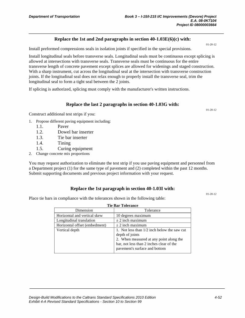
Department of Transportation Book 3 – I-15/I-215 I/C Improvements (Devore) Project E.A. 08-0K7104 Project ID 08000003664
Design-Build Modifications to the Caltrans Standard Specifications 2010 Edition 4-52 Exhibit 4-A Revised Standard Specifications - Section 10 to Section 99
Replace the 1st and 2nd paragraphs in section 40-1.03E(6)(c) with: 01-20-12
Install preformed compressions seals in isolation joints if specified in the special provisions.
Install longitudinal seals before transverse seals. Longitudinal seals must be continuous except splicing is allowed at intersections with transverse seals. Transverse seals must be continuous for the entire transverse length of concrete pavement except splices are allowed for widenings and staged construction. With a sharp instrument, cut across the longitudinal seal at the intersection with transverse construction joints. If the longitudinal seal does not relax enough to properly install the transverse seal, trim the longitudinal seal to form a tight seal between the 2 joints.
If splicing is authorized, splicing must comply with the manufacturer's written instructions.
Replace the last 2 paragraphs in section 40-1.03G with: 01-20-12
Construct additional test strips if you:
1. Propose different paving equipment including: 1.1. Paver 1.2. Dowel bar inserter 1.3. Tie bar inserter 1.4. Tining 1.5. Curing equipment
2. Change concrete mix proportions You may request authorization to eliminate the test strip if you use paving equipment and personnel from a Department project (1) for the same type of pavement and (2) completed within the past 12 months. Submit supporting documents and previous project information with your request.
Replace the 1st paragraph in section 40-1.03I with: 01-20-12
Place tie bars in compliance with the tolerances shown in the following table:
Tie Bar Tolerance Dimension Tolerance
Horizontal and vertical skew 10 degrees maximum Longitudinal translation ± 2 inch maximum Horizontal offset (embedment) ± 2 inch maximum Vertical depth 1. Not less than 1/2 inch below the saw cut
depth of joints 2. When measured at any point along the bar, not less than 2 inches clear of the pavement's surface and bottom
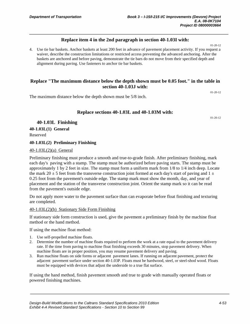
Department of Transportation Book 3 – I-15/I-215 I/C Improvements (Devore) Project E.A. 08-0K7104 Project ID 08000003664
Design-Build Modifications to the Caltrans Standard Specifications 2010 Edition 4-53 Exhibit 4-A Revised Standard Specifications - Section 10 to Section 99
Replace item 4 in the 2nd paragraph in section 40-1.03I with: 01-20-12
4. Use tie bar baskets. Anchor baskets at least 200 feet in advance of pavement placement activity. If you request a waiver, describe the construction limitations or restricted access preventing the advanced anchoring. After the baskets are anchored and before paving, demonstrate the tie bars do not move from their specified depth and alignment during paving. Use fasteners to anchor tie bar baskets.
Replace "The maximum distance below the depth shown must be 0.05 foot." in the table in section 40-1.03J with:
01-20-12
The maximum distance below the depth shown must be 5/8 inch.
Replace sections 40-1.03L and 40-1.03M with: 01-20-12
40-1.03L Finishing 40-1.03L(1) General Reserved
40-1.03L(2) Preliminary Finishing
40-1.03L(2)(a) General
Preliminary finishing must produce a smooth and true-to-grade finish. After preliminary finishing, mark each day's paving with a stamp. The stamp must be authorized before paving starts. The stamp must be approximately 1 by 2 feet in size. The stamp must form a uniform mark from 1/8 to 1/4 inch deep. Locate the mark 20 ± 5 feet from the transverse construction joint formed at each day's start of paving and 1 ± 0.25 foot from the pavement's outside edge. The stamp mark must show the month, day, and year of placement and the station of the transverse construction joint. Orient the stamp mark so it can be read from the pavement's outside edge.
Do not apply more water to the pavement surface than can evaporate before float finishing and texturing are completed.
40-1.03L(2)(b) Stationary Side Form Finishing
If stationary side form construction is used, give the pavement a preliminary finish by the machine float method or the hand method.
If using the machine float method:
1. Use self-propelled machine floats. 2. Determine the number of machine floats required to perform the work at a rate equal to the pavement delivery
rate. If the time from paving to machine float finishing exceeds 30 minutes, stop pavement delivery. When machine floats are in proper position, you may resume pavement delivery and paving.
3. Run machine floats on side forms or adjacent pavement lanes. If running on adjacent pavement, protect the adjacent pavement surface under section 40-1.03P. Floats must be hardwood, steel, or steel-shod wood. Floats must be equipped with devices that adjust the underside to a true flat surface.
If using the hand method, finish pavement smooth and true to grade with manually operated floats or powered finishing machines.
Department of Transportation Book 3 – I-15/I-215 I/C Improvements (Devore) Project E.A. 08-0K7104 Project ID 08000003664
Design-Build Modifications to the Caltrans Standard Specifications 2010 Edition 4-54 Exhibit 4-A Revised Standard Specifications - Section 10 to Section 99
40-1.03L(2)(c) Slip-Form Finishing
If slip-form construction is used, the slip-form paver must give the pavement a preliminary finish. You may supplement the slip-form paver with machine floats.
Before the pavement hardens, correct pavement edge slump in excess of 0.02 foot exclusive of edge rounding.
40-1.03L(3) Final Finishing After completing preliminary finishing, round the edges of the initial paving widths to a 0.04-foot radius. Round transverse and longitudinal construction joints to a 0.02-foot radius.
Before curing, texture the pavement. Perform initial texturing with a burlap drag or broom device that produces striations parallel to the centerline. Perform final texturing with a steel-tined device that produces grooves parallel with the centerline.
Construct longitudinal grooves with a self-propelled machine designed specifically for grooving and texturing pavement. The machine must have tracks to maintain constant speed, provide traction, and maintain accurate tracking along the pavement surface. The machine must have a single row of rectangular spring steel tines. The tines must be from 3/32 to 1/8 inch wide, on 3/4-inch centers, and must have enough length, thickness, and resilience to form grooves approximately 3/16 inch deep. The machine must have horizontal and vertical controls. The machine must apply constant down pressure on the pavement surface during texturing. The machines must not cause ravels.
Construct grooves over the entire pavement width in a single pass except do not construct grooves 3 inches from the pavement edges and longitudinal joints. Final texture must be uniform and smooth. Use a guide to properly align the grooves. Grooves must be parallel and aligned to the pavement edge across the pavement width. Grooves must be from 1/8 to 3/16 inch deep after the pavement has hardened.
For irregular areas and areas inaccessible to the grooving machine, you may hand-construct grooves under section 40-1.03L(2) using the hand method. Hand-constructed grooves must comply with the specifications for machine-constructed grooves.
Initial and final texturing must produce a coefficient of friction of at least 0.30 when tested under California Test 342. Notify the Engineer when the pavement is scheduled to be opened to traffic to allow at least 25 days for the Department to schedule testing for coefficient of friction. Notify the Engineer when the pavement is ready for testing which is the latter of:
1. Seven days after paving 2. When the pavement has attained a modulus of rupture of 550 psi The Department tests for coefficient of friction within 7 days of receiving notification that the pavement is ready for testing.
Do not open the pavement to traffic unless the coefficient of friction is at least 0.30.
40-1.03M Reserved
Replace the 4th paragraph of 40-1.03P with: 01-20-12
Construct crossings for traffic convenience. If authorized, you may use RSC for crossings. Do not open crossings until the Department determines that the pavement's modulus of rupture is at least 550 psi under California Test 523 or California Test 524.

Department of Transportation Book 3 – I-15/I-215 I/C Improvements (Devore) Project E.A. 08-0K7104 Project ID 08000003664
Design-Build Modifications to the Caltrans Standard Specifications 2010 Edition 4-55 Exhibit 4-A Revised Standard Specifications - Section 10 to Section 99
Replace the 1st paragraph of section 40-6.01A with: 01-20-12
Section 40-6 includes specifications for applying a high molecular weight methacrylate resin system to pavement surface cracks that do not extend the full slab depth.
Replace the 4th paragraph of section 40-6.01C(2) with: 01-20-12
If the project is in an urban area adjacent to a school or residence, the public safety plan must also include an airborne emissions monitoring plan prepared by a CIH certified in comprehensive practice by the American Board of Industrial Hygiene. Submit a copy of the CIH's certification. The CIH must monitor the emissions at a minimum of 4 points including the mixing point, the application point, and the point of nearest public contact. At work completion, submit a report by the industrial hygienist with results of the airborne emissions monitoring plan.
01-20-12
Delete the 1st sentence of the 2nd paragraph in section 40-6.02B.
Replace the 4th item in the last paragraph in section 40-6.03A with: 01-20-12
4. Coefficient of friction is at least 0.30 under California Test 342
Replace the paragraph in section 40-6.04 with: 01-20-12
Not Used
Add to section 40: 01-20-12
40-7–40-15 RESERVED
^^^^^^^^^^^^^^^^^^^^^^^^^^^^^^^^^^^^^^^^^^^^^^^^^^^^^^^^^^^^
DIVISION VI STRUCTURES 47 EARTH RETAINING SYSTEMS
02-17-12 Replace the 2nd paragraph of section 47-2.01D with:
02-17-12
Coupler test samples must comply with minimum tensile specifications for steel wire in ASTM A 82/A 82M. Total wire slip must be at most 3/16 inch when tested under the specifications for tension testing of round wire test samples in ASTM A 370.
Department of Transportation Book 3 – I-15/I-215 I/C Improvements (Devore) Project E.A. 08-0K7104 Project ID 08000003664
Design-Build Modifications to the Caltrans Standard Specifications 2010 Edition 4-56 Exhibit 4-A Revised Standard Specifications - Section 10 to Section 99
Replace the value for the sand equivalent requirement in the table titled "Property Requirements" in the 3rd paragraph of section 47-2.02C with:
01-20-12
12 minimum
Replace the 1st paragraph of section 47-2.02E with: 02-17-12
Steel wire must comply with ASTM A 82/A 82M. Welded wire reinforcement must comply with ASTM A 185/A 185M.
^^^^^^^^^^^^^^^^^^^^^^^^^^^^^^^^^^^^^^^^
48 TEMPORARY STRUCTURES 09-16-11
Replace the 7th paragraph of section 48-2.01C(2) with: 09-16-11
If you submit multiple submittals at the same time or additional submittals before review of a previous submittal is complete:
1. You must designate a review sequence for submittals 2. Review time for any submittal is the review time specified plus 15 days for each submittal of higher priority
still under review
^^^^^^^^^^^^^^^^^^^^^^^^^^^^^^^^^^^^^^^^
49 PILING 01-20-12
Replace the 2nd paragraph of section 49-2.01D with: 01-20-12
Furnish piling is measured along the longest side of the pile from the specified tip elevation shown to the plane of pile cutoff.
Add to section 49-3.01A: 01-20-12
Concrete must comply with section 51.
Replace the 1st paragraph of section 49-3.01C with: 01-20-12
Except for CIDH concrete piles constructed under slurry, construct CIP concrete piles such that the excavation methods and the concrete placement procedures provide for placing the concrete against undisturbed material in a dry or dewatered hole.
Department of Transportation Book 3 – I-15/I-215 I/C Improvements (Devore) Project E.A. 08-0K7104 Project ID 08000003664
Design-Build Modifications to the Caltrans Standard Specifications 2010 Edition 4-57 Exhibit 4-A Revised Standard Specifications - Section 10 to Section 99
Replace "Reserved" in section 49-3.02A(2) with: 01-20-12
dry hole:
1. Except for CIDH concrete piles specified as end bearing, a drilled hole that: 1.1. Accumulates no more than 12 inches of water in the bottom of the drilled hole
during a period of 1 hour without any pumping from the hole during the hour. 1.2. Has no more than 3 inches of water in the bottom of the drilled hole immediately
before placing concrete. 2. For CIDH concrete piles specified as end bearing, a drilled hole free of water without the use of pumps.
Replace "Reserved" in section 49-3.02A(3)(a) with: 01-20-12
If plastic spacers are proposed for use, submit the manufacturer's data and a sample of the plastic spacer. Allow 10 days for review.
Replace item 2 in the 1st paragraph of section 49-3.02A(3)(g) with: 01-20-12
2. Be sealed and signed by an engineer who is registered as a civil engineer in the State. This requirement is waived for either of the following conditions: 2.1 The proposed mitigation will be performed under the current Department-published
version of ADSC Standard Mitigation Plan 'A' - Basic Repair without exception or modification.
2.2 The Engineer determines that the rejected pile does not require mitigation due to structural, geotechnical, or corrosion concerns, and you elect to repair the pile using the current Department-published version of ADSC Standard Mitigation Plan 'B' - Grouting Repair without exception or modification.
Replace item 1 in the 1st paragraph of section 49-3.02A(4)(d)(ii) with: 01-20-12
1. Inspection pipes must be schedule 40 PVC pipe complying with ASTM D 1785 with a nominal pipe size of 2 inches. Watertight PVC couplers complying with ASTM D 2466 are allowed to facilitate pipe lengths in excess of those commercially available. Log the location of the inspection pipe couplers with respect to the plane of pile cutoff.
Add to section 49-3.02A(4)(d)(iv): 01-20-12
If the Engineer determines it is not feasible to use one of ADSC's standard mitigation plans to mitigate the pile, schedule a meeting and meet with the Engineer before submitting a nonstandard mitigation plan.
The meeting attendees must include your representatives and the Engineer's representatives involved in the pile mitigation. The purpose of the meeting is to discuss the type of pile mitigation acceptable to the Department.
Provide the meeting facility. The Engineer conducts the meeting.
Department of Transportation Book 3 – I-15/I-215 I/C Improvements (Devore) Project E.A. 08-0K7104 Project ID 08000003664
Design-Build Modifications to the Caltrans Standard Specifications 2010 Edition 4-58 Exhibit 4-A Revised Standard Specifications - Section 10 to Section 99
Replace the 1st paragraph of section 49-3.02B(5) with: 01-20-12
Grout used to backfill casings must comply with section 50-1.02C, except:
1. Grout must consist of cementitious material and water, and may contain an admixture if authorized. Cementitious material must comply with section 90-1.02B, except SCMs are not required. The minimum cementitious material content of the grout must not be less than 845 lb/cu yd of grout.
2. Aggregate must be used to extend the grout as follows: 2.1 Aggregate must consist of at least 70 percent fine aggregate and approximately 30
percent pea gravel, by weight. 2.2 Fine aggregate must comply with section 90-1.02C(3). 2.3 Size of pea gravel must be such that 100 percent passes the 1/2-inch sieve, at least 90
percent passes the 3/8-inch sieve, and not more than 5 percent passes the no. 8 sieve. 3. California Test 541 is not required. 4. Grout is not required to pass through a sieve with a 0.07-inch maximum clear opening before being introduced
into the grout pump.
Replace section 49-3.02B(8) with: 01-20-12
49-3.02B(8) Spacers Spacers must comply with section 52-1.03D, except you may use plastic spacers.
Plastic spacers must:
1. Comply with sections 3.4 and 3.5 of the Concrete Reinforcing Steel Institute's Manual of Standard Practice 2. Have at least 25 percent of their gross plane area perforated to compensate for the difference in the coefficient
of thermal expansion between the plastic and concrete 3. Be of commercial quality
Add to section 49-3.02C(4): 01-20-12
Unless otherwise shown, the bar reinforcing steel cage must have at least 3 inches of clear cover measured from the outside of the cage to the sides of the hole or casing.
Place spacers at least 5 inches clear from any inspection tubes.
Place plastic spacers around the circumference of the cage and at intervals along the length of the cage, as recommended by the manufacturer.
Department of Transportation Book 3 – I-15/I-215 I/C Improvements (Devore) Project E.A. 08-0K7104 Project ID 08000003664
Design-Build Modifications to the Caltrans Standard Specifications 2010 Edition 4-59 Exhibit 4-A Revised Standard Specifications - Section 10 to Section 99
^^^^^^^^^^^^^^^^^^^^^^^^^^^^^^^^^^^^^^^^
50 PRESTRESSING CONCRETE 01-20-12
Add to section 50-1.02: 09-16-11
50-1.02G Sheathing Sheathing for debonding prestressing strand must:
1. Be split or un-split flexible polymer plastic tubing 1. Have a minimum wall thickness of 0.025 inch 2. Have an inside diameter exceeding the maximum outside diameter of the strand by 0.025 to 0.14 inch Split sheathing must overlap at least 3/8 inch.
Waterproofing tape used to seal the ends of the sheathing must be flexible adhesive tape.
The sheathing and waterproof tape must not react with the concrete, coating, or steel.
Add to section 50-1.03B(1): 01-20-12
After seating, the maximum tensile stress in the prestressing steel must not exceed 75 percent of the minimum ultimate tensile strength shown.
Add to section 50-1.03B(2): 09-16-11
50-1.03B(2)(e) Debonding Prestressing Strands
Where shown, debond prestressing strands by encasing the strands in plastic sheathing along the entire length shown and sealing the ends of the sheathing with waterproof tape.
Distribute the debonded strands symmetrically about the vertical centerline of the girder. The debonded lengths of pairs of strands must be equal.
Do not terminate debonding at any one cross section of the member for more than 40 percent of the debonded strands or 4 strands, whichever is greater.
Thoroughly seal the ends with waterproof tape to prevent the intrusion of water or cement paste before placing the concrete.

Department of Transportation Book 3 – I-15/I-215 I/C Improvements (Devore) Project E.A. 08-0K7104 Project ID 08000003664
Design-Build Modifications to the Caltrans Standard Specifications 2010 Edition 4-60 Exhibit 4-A Revised Standard Specifications - Section 10 to Section 99
^^^^^^^^^^^^^^^^^^^^^^^^^^^^^^^^^^^^^^^^
51 CONCRETE STRUCTURES 08-05-11
Add to section 51-1.03E(5): 08-05-11
Drill the holes without damaging the adjacent concrete. If reinforcement is encountered during drilling before the specified depth is attained, notify the Engineer. Unless coring through the reinforcement is authorized, drill a new hole adjacent to the rejected hole to the depth shown.
Replace the 2nd paragraph of section 51-2.02E(1)(e) with: 08-05-11
Except for components in contact with the tires, the design loading must be the AASHTO LRFD Bridge Design Specifications Design Truck with 100 percent dynamic load allowance. Each component in contact with the tires must support a minimum of 80 percent of the AASHTO LRFD Bridge Design Specifications Design Truck with 100 percent dynamic load allowance. The tire contact area must be 10 inches measured normal to the longitudinal assembly axis by 20 inches wide. The assembly must provide a smooth-riding joint without slapping of components or tire rumble.
^^^^^^^^^^^^^^^^^^^^^^^^^^^^^^^^^^^^^^^^
52 REINFORCEMENT 10-21-11
Replace section 52-6.02D with: 10-21-11
52-6.02D Ultimate Butt Splice Requirements When tested under California Test 670, ultimate butt splice test samples must demonstrate necking as either of the following:
1. For "Necking (Option I)," the test sample must rupture in the reinforcing bar outside of the affected zone and show visible necking.
2. For "Necking (Option II)," the largest measured strain must be at least: 2.1 Six percent for no. 11 and larger bars 2.2 Nine percent for no. 10 and smaller bars

Department of Transportation Book 3 – I-15/I-215 I/C Improvements (Devore) Project E.A. 08-0K7104 Project ID 08000003664
Design-Build Modifications to the Caltrans Standard Specifications 2010 Edition 4-61 Exhibit 4-A Revised Standard Specifications - Section 10 to Section 99
^^^^^^^^^^^^^^^^^^^^^^^^^^^^^^^^^^^^^^^^
58 SOUND WALLS 08-05-11
Replace the 1st paragraph of section 58-2.01D(5)(a) with: 08-05-11
You must employ a special inspector and an authorized laboratory to perform Level 1 inspections and structural tests of masonry to verify the masonry construction complies with section 1704, "Special Inspections," and section 2105, "Quality Assurance," of the 2007 CBC.
^^^^^^^^^^^^^^^^^^^^^^^^^^^^^^^^^^^^^^^^^^^^^^^^^^^^^^^^^^^^
DIVISION VII DRAINAGE 70 MISCELLANEOUS DRAINAGE FACILITIES
01-20-12 Replace section 70-5.02A(2) with:
01-20-12
70-5.02A(2) Plastic Flared End Sections Plastic flared end sections must comply with ASTM D 3350.
^^^^^^^^^^^^^^^^^^^^^^^^^^^^^^^^^^^^^^^^^^^^^^^^^^^^^^^^^^^^
DIVISION VIII MISCELLANEOUS CONSTRUCTION 72 SLOPE PROTECTION
01-20-12 Replace the row under "Class" in the table titled "Concreted-Rock Grading" in section 72-
3.02B with: 01-20-12
1/2 T 1/4 T Light Facing Cobble
Replace the row under "Rock class" in the table titled "Minimum Concrete Penetration" in section 72-3.03E with:
01-20-12
1/2 T 1/4 T Light Facing Cobble

Department of Transportation Book 3 – I-15/I-215 I/C Improvements (Devore) Project E.A. 08-0K7104 Project ID 08000003664
Design-Build Modifications to the Caltrans Standard Specifications 2010 Edition 4-62 Exhibit 4-A Revised Standard Specifications - Section 10 to Section 99
^^^^^^^^^^^^^^^^^^^^^^^^^^^^^^^^^^^^^^^^
74 PUMPING EQUIPMENT AND CONTROLS 01-20-12
Replace the 1st sentence of the 1st paragraph in section 74-2.01D(2) with: 01-20-12
Drainage pumps must be factory certified under ANSI/HI 14.6.
^^^^^^^^^^^^^^^^^^^^^^^^^^^^^^^^^^^^^^^^^^^^^^^^^^^^^^^^^^^^
DIVISION IX TRAFFIC CONTROL FACILITIES 83 RAILINGS AND BARRIERS
10-21-11 Add to section 83-2.02D(1):
10-21-11
For a concrete barrier transition:
1. Remove portions of the existing concrete barrier where shown under section 15-3 2. Roughen the contact surface of the existing concrete barrier 3. Drill and bond dowels into the existing concrete barrier under section 51-1
^^^^^^^^^^^^^^^^^^^^^^^^^^^^^^^^^^^^^^^^
84 TRAFFIC STRIPES AND PAVEMENT MARKINGS 01-20-12
Replace the 1st paragraph in section 84-2.04 with: 01-20-12
A double extruded thermoplastic traffic stripe consisting of two 4-inch wide yellow stripes is measured as 2 traffic stripes.
A double sprayable thermoplastic traffic stripe consisting of two 4-inch wide yellow stripes is measured as 1 traffic stripe.
Add to section 84: 01-20-12
84-6 THERMOPLASTIC TRAFFIC STRIPES AND PAVEMENT MARKINGS WITH ENHANCED WET NIGHT VISIBILITY
Reserved
84-7–84-10 RESERVED
Department of Transportation Book 3 – I-15/I-215 I/C Improvements (Devore) Project E.A. 08-0K7104 Project ID 08000003664
Design-Build Modifications to the Caltrans Standard Specifications 2010 Edition 4-63 Exhibit 4-A Revised Standard Specifications - Section 10 to Section 99
^^^^^^^^^^^^^^^^^^^^^^^^^^^^^^^^^^^^^^^^
86 ELECTRICAL SYSTEMS 01-20-12
Replace section 86-2.06 with: 01-20-12
86-2.06 PULL BOXES
86-2.06A General 86-2.06A(1) Cover Marking Marking must be clearly defined, uniform in depth, and parallel to either the long or short sides of the cover.
Marking letters must be 1 to 3 inches high.
Before galvanizing steel or cast iron cover, apply marking by one of the following methods:
1. Use cast iron strip at least 1/4 inch thick with letters raised a minimum of 1/16 inch. Fasten strip to cover with 1/4-inch flathead stainless steel machine bolts and nuts. Peen bolts after tightening.
2. Use sheet steel strip at least 0.027 inch thick with letters raised a minimum of 1/16 inch. Fasten strip to cover by spot welding, tack welding, or brazing, with 1/4-inch stainless steel rivets or 1/4-inch roundhead stainless steel machine bolts and nuts. Peen bolts after tightening.
3. Bead weld the letters on cover such that the letters are raised a minimum of 3/32 inch.
86-2.06A(2) Installation and Use Space pull boxes no more than 200 feet apart. You may install additional pull boxes to facilitate the work.
You may use a larger standard size pull box than that shown on the plans or specified.
A pull box in ground or sidewalk area must be installed as follows:
1. Embed bottom of the pull box in crushed rock. 2. Place a layer of roofing paper on the crushed rock. 3. Place grout over the layer of roofing paper. Grout must be 0.50 to 1 inch thick and sloped toward the drain hole. 4. Make a 1-inch drain hole in the center of the pull box through the grout and roofing paper. 5. Place grout between the pull box and the pull box extension, and around conduits. The top of the pull box must be flush with the surrounding grade or the top of an adjacent curb, except in unpaved areas where the pull box is not immediately adjacent to and protected by a concrete foundation, pole, or other protective construction. Place the pull box 1-1/4 inches above the surrounding grade. Where practical, place a pull box shown in the vicinity of curbs or adjacent to a standard on the side of the foundation facing away from traffic. If a pull box is installed in a sidewalk area, adjust the depth of the pull box so that the top of the pull box is flush with the sidewalk.
Reconstruct the sump of an existing pull box if disturbed by your activities. Remove old grout and replace with new if the sump was grouted.
86-2.06B Non-Traffic-Rated Pull Boxes Reserved
86-2.06C Traffic Pull Boxes Traffic pull box and cover must comply with ASTM C857, "Standard Practice for Minimum Structural Design Loading for Underground Precast Concrete Utility Structures," for HS20-44 loading. You must be
Department of Transportation Book 3 – I-15/I-215 I/C Improvements (Devore) Project E.A. 08-0K7104 Project ID 08000003664
Design-Build Modifications to the Caltrans Standard Specifications 2010 Edition 4-64 Exhibit 4-A Revised Standard Specifications - Section 10 to Section 99
able to place the load anywhere on the box and cover for 1 minute without causing cracks or permanent deformations.
Frame must be anchored to the box with 1/4 by 2-1/4 inch concrete anchors. Four concrete anchors must be included for No. 3-1/2(T) pull box; one placed in each corner. Six concrete anchors must be included for No. 5(T) and No. 6(T) pull boxes; one placed in each corner and one near the middle of each of the longer sides.
Nuts must be zinc-plated carbon steel, vibration resistant, and have a wedge ramp at the root of the thread.
After installation of traffic pull box, install the steel cover and keep it bolted down when your activities are not in progress at the pull box. When the steel cover is placed for the final time, the cover and Z bar frame must be cleaned of debris and tightened securely.
Steel cover must be countersunk approximately 1/4 inch to accommodate the bolt head. When tightened, the bolt head must not exceed more than 1/8 inch above the top of the cover.
Concrete placed around and under traffic pull boxes must be minor concrete.
^^^^^^^^^^^^^^^^^^^^^^^^^^^^^^^^^^^^^^^^
88 GEOSYNTHETICS 01-20-12
Replace the row for hydraulic bursting strength in the table in the 2nd paragraph of section 88-1.02B with:
01-20-12
Puncture strength, lb min
ASTM D 6241
600
Replace the value for permittivity of woven fabric in the table in the 1st paragraph of section 88-1.02E with:
01-20-12
0.05
Replace the value for apparent size opening of nonwoven fabric in the table in the 1st paragraph of section 88-1.02E with:
01-20-12
0.012
Replace the table in the 1st paragraph of section 88-1.02G with: 01-20-12
Sediment Filter Bag
Property Test Values
Woven Nonwoven Grab breaking load, lb, 1-inch grip ASTM D 4632 200 250
Department of Transportation Book 3 – I-15/I-215 I/C Improvements (Devore) Project E.A. 08-0K7104 Project ID 08000003664
Design-Build Modifications to the Caltrans Standard Specifications 2010 Edition 4-65 Exhibit 4-A Revised Standard Specifications - Section 10 to Section 99
min, in each direction Apparent elongation, percent min, in each direction
ASTM D 4632 10 50
Water flow rate, gal per minute/sq ft min and max average roll value
ASTM D 4491 100-200 75-200
Permittivity, sec-1 min
ASTM D 4491 1.0 1.0
Apparent opening size, inches max average roll value
ASTM D 4751 0.023 0.012
Ultraviolet resistance, % min retained grab breaking load, 500 hr.
ASTM D 4355 70 70
Replace the table in the 1st paragraph of section 88-1.02H with: 01-20-12
Temporary Cover
Property Test Values
Woven Nonwoven Grab breaking load, lb, 1-inch grip
min, in each direction ASTM D 4632 200 200
Apparent elongation, percent min, in each direction
ASTM D 4632 15 50
Water flow rate, gal per minute/sq ft min and max average roll value
ASTM D 4491 4-10 80-120
Permittivity, sec-1 min
ASTM D 4491 0.05 1.0
Apparent opening size, inches max average roll value
ASTM D 4751 0.023 0.012
Ultraviolet resistance, % min retained grab breaking load, 500 hr.
ASTM D 4355 70 70
^^^^^^^^^^^^^^^^^^^^^^^^^^^^^^^^^^^^^^^^^^^^^^^^^^^^^^^^^^^^
DIVISION X MATERIALS 90 CONCRETE
08-05-11 Replace the 3rd paragraph of section 90-1.01C(7) with:
08-05-11
Submit weighmaster certificates in printed form or, if authorized, in electronic media. Present electronic media in a tab-delimited format on a CD or DVD. Captured data for the ingredients represented by each batch must be line feed carriage return and one line separate record with sufficient fields for the specified data.

Department of Transportation Book 3 – I-15/I-215 I/C Improvements (Devore) Project E.A. 08-0K7104 Project ID 08000003664
Design-Build Modifications to the Caltrans Standard Specifications 2010 Edition 4-66 Exhibit 4-A Revised Standard Specifications - Section 10 to Section 99
Replace the 3rd paragraph of section 90-3.01C(5) with: 08-05-11
Production data must be input by hand into a pre-printed form or captured and printed by the proportioning device. Present electronic media containing recorded production data in a tab-delimited format on a CD or DVD. Each capture of production data must be followed by a line feed carriage return with sufficient fields for the specified data.
^^^^^^^^^^^^^^^^^^^^^^^^^^^^^^^^^^^^^^^^
92 ASPHALTS 01-20-12
Replace the row for dynamic shear for original binder in the table in the 1st paragraph of section 92-1.02B with:
01-20-12
Dynamic shear, Test temperature at 10 rad/s, °C min G*/sin(delta), kPa max G*/sin(delta), kPa
T 315 58 1.00 2.00
64 1.00 2.00
64 1.00 2.00
64 1.00 2.00
70 1.00 2.00

Department of Transportation Book 3 – I-15/I-215 I/C Improvements (Devore) Project E.A. 08-0K7104 Project ID 08000003664
Modifications To Special Provisions 5-1
5 MODIFICATIONS TO SPECIAL PROVISIONS
5.1 General The following non-Standard Special Provisions (nSSP) listed in this Section 5 shall be used when the item specified is included in the work for this Project.
5.2 Draft nSSPs The following nSSPs are in draft format and shall be edited by the Design-Builder according to the instructions in the hidden text included in the nSSP, and the guidelines given in the Department’s Ready-To-List Guide. Once edits are complete, the nSSP shall be submitted to the Department for review and approval. Edits to these nSSPs within the limits of what is allowed by the hidden text instructions of the nSSP will require up to two weeks for each review by the Department. Edits beyond what is allowed by the hidden text instructions will require up to four weeks for each review. The Design Builder shall bear the risk of schedule impacts associated with nSSP reviews. Once approved for use, each approved nSSP shall follow the same process as Standard Special Provisions (SSPs) for inclusion in RFC packages, except that written notice of approval shall accompany the nSSP.
1. Lean Concrete Base Rapid Setting 2. Hot Mix Asphalt Type A – Bond Breaker 3. Hot Mix Asphalt (Type C) 4. Jointed Plain Concrete Pavement (Rapid Strength Concrete) 5. Wireless Ethernet Radio (WER) 6. Modify Fiber Optic Communication System 7. Modify Communication System Transportation Management Center (TMC) 8. Closed Circuit Television Systems
5.3 Approved nSSPs The following nSSPs are pre-approved for use on this project and shall be edited by the Design-Builder only according to the instruction in the hidden text included in the nSSP, and the guidelines given in the Department’s Ready-To-List Guide. These nSSPs shall follow the same process as Standard Special Provisions (SSPs) for inclusion in RFC packages.
9. Drainage Inlet Protection 10. Flared End Section Protection 11. Drainage Outlet Protection 12. Check Dam
Department of Transportation Book 3 – I-15/I-215 I/C Improvements (Devore) Project E.A. 08-0K7104 Project ID 08000003664
Modifications To Special Provisions 5-2
1. Lean Concrete Base Rapid Setting XE "28-LCBRS_E_D11-16-11_nSSP. "
Page 1 of 10
10-1.__ LEAN CONCRETE BASE RAPID SETTING GENERAL
Summary
1
Lean concrete base rapid setting (LCBRS) must comply with Section 28, "Lean Concrete Base," of the Standard Specifications and these special provisions.
2 Definitions
final set time: Time a specific penetration resistance of 4,000 psi is achieved, determined under ASTM C 403.
opening age: Time the concrete achieves the specified strength for opening to traffic. Submittals
Mix Design
3
Determine the mix proportions for LCBRS and submit mix designs.
4
At least 10 days before use, submit a mix design for LCBRS that includes: 1. Opening age 2. Proposed aggregate gradation 3. Proportions of hydraulic cement and aggregate 4. Types and amounts of chemical admixtures 5. Maximum time allowed between batching and placing 6. Range of ambient temperatures over which the mix design is effective 7. Final set time 8. Test result from California Test 548 testing, if required
5
Submit more than 1 mix design to plan for ambient temperature variations anticipated during LCBRS placement. Each mix design must have a maximum ambient temperature range of 18 °F.
6
LCBRS Field Qualification Submit field qualification data and test reports including:
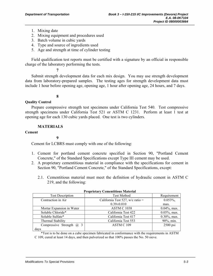
Department of Transportation Book 3 – I-15/I-215 I/C Improvements (Devore) Project E.A. 08-0K7104 Project ID 08000003664
Modifications To Special Provisions 5-3
1. Mixing date 2. Mixing equipment and procedures used 3. Batch volume in cubic yards 4. Type and source of ingredients used 5. Age and strength at time of cylinder testing Field qualification test reports must be certified with a signature by an official in responsible
charge of the laboratory performing the tests.
7
Submit strength development data for each mix design. You may use strength development data from laboratory-prepared samples. The testing ages for strength development data must include 1 hour before opening age, opening age, 1 hour after opening age, 24 hours, and 7 days.
8 Quality Control
Prepare compressive strength test specimens under California Test 540. Test compressive strength specimens under California Test 521 or ASTM C 1231. Perform at least 1 test at opening age for each 130 cubic yards placed. One test is two cylinders.
MATERIALS
Cement
9
Cement for LCBRS must comply with one of the following: 1. Cement for portland cement concrete specified in Section 90, "Portland Cement
Concrete," of the Standard Specifications except Type III cement may be used. 2. A proprietary cementitious material in compliance with the specifications for cement in
Section 90, "Portland Cement Concrete," of the Standard Specifications, except:
2.1. Cementitious material must meet the definition of hydraulic cement in ASTM C 219, and the following:
Proprietary Cementitious Material
Test Description Test Method Requirement Contraction in Air California Test 527, w/c ratio =
0.39±0.010 0.053%, max.
Mortar Expansion in Water ASTM C 1038 0.04%, max. Soluble Chloride* California Test 422 0.05%, max. Soluble Sulfate* California Test 417 0.30%, max. Thermal Stability California Test 553 90%, min. Compressive Strength @ 3
days ASTM C 109 2500 psi
*Test is to be done on a cube specimen fabricated in conformance with the requirements in ASTM C 109, cured at least 14 days, and then pulverized so that 100% passes the No. 50 sieve.
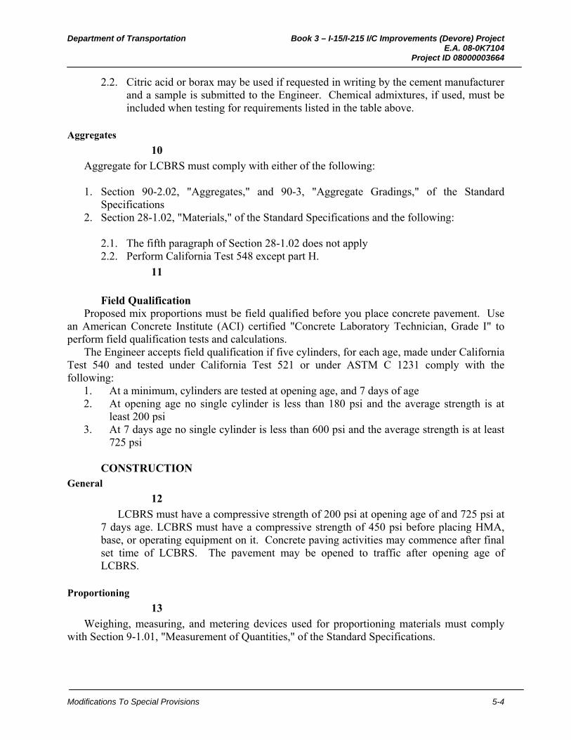
Department of Transportation Book 3 – I-15/I-215 I/C Improvements (Devore) Project E.A. 08-0K7104 Project ID 08000003664
Modifications To Special Provisions 5-4
2.2. Citric acid or borax may be used if requested in writing by the cement manufacturer and a sample is submitted to the Engineer. Chemical admixtures, if used, must be included when testing for requirements listed in the table above.
Aggregates
10
Aggregate for LCBRS must comply with either of the following: 1. Section 90-2.02, "Aggregates," and 90-3, "Aggregate Gradings," of the Standard
Specifications 2. Section 28-1.02, "Materials," of the Standard Specifications and the following:
2.1. The fifth paragraph of Section 28-1.02 does not apply 2.2. Perform California Test 548 except part H.
11
Field Qualification
Proposed mix proportions must be field qualified before you place concrete pavement. Use an American Concrete Institute (ACI) certified "Concrete Laboratory Technician, Grade I" to perform field qualification tests and calculations.
The Engineer accepts field qualification if five cylinders, for each age, made under California Test 540 and tested under California Test 521 or under ASTM C 1231 comply with the following:
1. At a minimum, cylinders are tested at opening age, and 7 days of age 2. At opening age no single cylinder is less than 180 psi and the average strength is at
least 200 psi 3. At 7 days age no single cylinder is less than 600 psi and the average strength is at least
725 psi
CONSTRUCTION General
12
LCBRS must have a compressive strength of 200 psi at opening age of and 725 psi at 7 days age. LCBRS must have a compressive strength of 450 psi before placing HMA, base, or operating equipment on it. Concrete paving activities may commence after final set time of LCBRS. The pavement may be opened to traffic after opening age of LCBRS.
Proportioning
13
Weighing, measuring, and metering devices used for proportioning materials must comply with Section 9-1.01, "Measurement of Quantities," of the Standard Specifications.
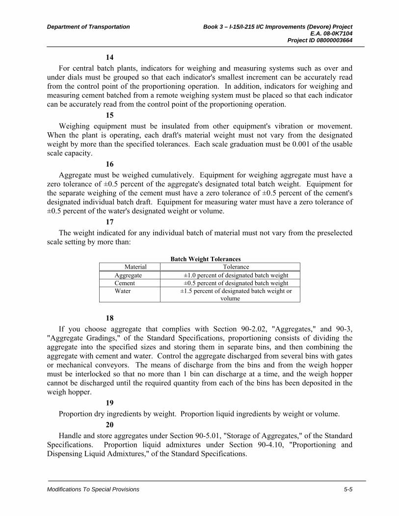
Department of Transportation Book 3 – I-15/I-215 I/C Improvements (Devore) Project E.A. 08-0K7104 Project ID 08000003664
Modifications To Special Provisions 5-5
14
For central batch plants, indicators for weighing and measuring systems such as over and under dials must be grouped so that each indicator's smallest increment can be accurately read from the control point of the proportioning operation. In addition, indicators for weighing and measuring cement batched from a remote weighing system must be placed so that each indicator can be accurately read from the control point of the proportioning operation.
15
Weighing equipment must be insulated from other equipment's vibration or movement. When the plant is operating, each draft's material weight must not vary from the designated weight by more than the specified tolerances. Each scale graduation must be 0.001 of the usable scale capacity.
16
Aggregate must be weighed cumulatively. Equipment for weighing aggregate must have a zero tolerance of ±0.5 percent of the aggregate's designated total batch weight. Equipment for the separate weighing of the cement must have a zero tolerance of ±0.5 percent of the cement's designated individual batch draft. Equipment for measuring water must have a zero tolerance of ±0.5 percent of the water's designated weight or volume.
17
The weight indicated for any individual batch of material must not vary from the preselected scale setting by more than:
Batch Weight Tolerances
Material Tolerance Aggregate ±1.0 percent of designated batch weight Cement ±0.5 percent of designated batch weight Water ±1.5 percent of designated batch weight or
volume
18
If you choose aggregate that complies with Section 90-2.02, "Aggregates," and 90-3, "Aggregate Gradings," of the Standard Specifications, proportioning consists of dividing the aggregate into the specified sizes and storing them in separate bins, and then combining the aggregate with cement and water. Control the aggregate discharged from several bins with gates or mechanical conveyors. The means of discharge from the bins and from the weigh hopper must be interlocked so that no more than 1 bin can discharge at a time, and the weigh hopper cannot be discharged until the required quantity from each of the bins has been deposited in the weigh hopper.
19
Proportion dry ingredients by weight. Proportion liquid ingredients by weight or volume.
20
Handle and store aggregates under Section 90-5.01, "Storage of Aggregates," of the Standard Specifications. Proportion liquid admixtures under Section 90-4.10, "Proportioning and Dispensing Liquid Admixtures," of the Standard Specifications.
Department of Transportation Book 3 – I-15/I-215 I/C Improvements (Devore) Project E.A. 08-0K7104 Project ID 08000003664
Modifications To Special Provisions 5-6
21
At the time of batching, dry and drain aggregates to a stable moisture content. Do not proportion aggregates with visible separation of water from the aggregate during proportioning. At the time of batching, the free moisture content of fine aggregate must not exceed 8 percent of its saturated, surface-dry weight.
22
If the proportioning plant has separate supplies of the same size group of aggregate with different moisture content, specific gravity, or surface characteristics affecting workability, exhaust 1 supply before using another supply.
23
Keep cement separated from the aggregate until discharged into the mixer. When discharged into the mixer, cement must be free of lumps and clods. Before reuse, clean fabric containers used for transportation or proportioning of cement.
24
Weigh systems for proportioning aggregate and cement must be individual and distinct from other weigh systems. Each weigh system must have a hopper, a lever system, and an indicator.
25. Delete Item 4 if Paras 29 through 57 are deleted (volumeric proportioning).
For batches with a volume of 1 cubic yard or more, proportioning must comply with one of the following methods:
1. Batch the ingredients at a central batch plant and charge them into a mixer truck for
transportation to the pour site. Proportion ingredients under Section 90-5, "Proportioning," of the Standard Specifications.
2. Batch the ingredients except the cement at a central batch plant and charge them into a mixer truck for transportation to a cement silo and weigh system, which must proportion cement for charging into the mixer truck.
3. Batch ingredients except the cement at a central batch plant and charge them into a mixer truck for transportation to a location where pre-weighed containerized cement is added to the mixer truck. The cement pre-weighing operation must utilize a platform scale. The platform scale must have a maximum capacity of 2.75 tons with a maximum graduation size of 1 pound. Pre-weigh cement into a fabric container. The minimum amount of cement to be proportioned into any single container must be 1/2 of the total amount required for the load of LCBRS being produced.
4. Cement, water, and aggregate are proportioned volumetrically.
26
When ordered by the Engineer, determine the gross weight and tare weight of truck mixers on scales designated by the Engineer.
27
Install and maintain in operating condition an electrically actuated moisture meter. The meter must indicate on a readily visible scale the changes in the fine aggregate moisture content as it is batched. The meter must have a sensitivity of 0.5 percent by weight of the fine aggregate.
Department of Transportation Book 3 – I-15/I-215 I/C Improvements (Devore) Project E.A. 08-0K7104 Project ID 08000003664
Modifications To Special Provisions 5-7
28
Obtain the Engineer's acceptance before mixing water into the concrete during hauling or after arrival at the delivery point. If the Engineer accepts additional water be incorporated into the concrete, the drum must revolve not less than 30 revolutions at mixing speed after the water is added and before starting discharge. Measure water added to the truck mixer at the job site through a meter in compliance with Section 9-1.01, "Measurement of Quantities," of the Standard Specifications.
Paras 29 through 57: Delete when "Volumetric Proportioning" is not an option on the project. Discuss with District or Headquarters Weights and Measures Coordinator and METS, Rigid Pavement & Structural Concrete Unit If volumetric proportioning is allowed only for a portion of the work, edit paragraph 25 to identify those locations. For example, for project where LCBRS is used for both new pavement and slab replacement, paragraph 25 could be edited to say “You may choose to proportion LCBRS by volume when placing underneath individual slab replacements.”
Volumetric Proportioning
29
You may choose to proportion LCBRS by volume.
30
Handle and store aggregates under Section 90-5.01, "Storage of Aggregates," of the Standard Specifications. Proportion liquid admixtures under Section 90-4.10, "Proportioning and Dispensing Liquid Admixtures," of the Standard Specifications.
31
Batch-mixer trucks must proportion cement, water, aggregate, and additives by volume. Aggregate feeders must be connected directly to the drive on the cement vane feeder. The cement feed rate must be tied directly to the feed rate for the aggregate and other ingredients. Only change the ratio of cement to aggregate by changing the gate opening for the aggregate feed. The drive shaft of the aggregate feeder must have a revolution counter reading to the nearest full or partial revolution of the aggregate delivery belt.
32
Proportion aggregate with a belt feeder operated with an adjustable cutoff gate delineated to the nearest quarter increment. The gate opening height must be readily determinable. Proportion cement by any method that complies with the accuracy tolerance specifications. Proportion water with a meter under Section 9-1.01, "Measurement and Payment," of the Standard Specifications.
33
Calibrate the cutoff gate for each batch-mixer truck used and for each aggregate source. Calibrate batch-mixer trucks at 3 different aggregate gate settings that are commensurate with production needs. Perform at least 2 calibration runs for each aggregate gate.
Department of Transportation Book 3 – I-15/I-215 I/C Improvements (Devore) Project E.A. 08-0K7104 Project ID 08000003664
Modifications To Special Provisions 5-8
34
Individual aggregate delivery rate check-runs must not deviate more than 1.0 percent from the mathematical average of all runs for the same gate and aggregate type. Each test run must be at least 1,000 pounds.
35
At the time of batching, dry and drain aggregates to a stable moisture content. Do not proportion aggregates with visible separation of water from the aggregate during proportioning. At the time of batching, the free moisture content of fine aggregate must not exceed 8 percent of its saturated, surface-dry weight.
36
If the proportioning plant has separate supplies of the same size group of aggregate with different moisture content, specific gravity, or surface characteristics affecting workability, exhaust 1 supply before using another supply.
37
Cover rotating and reciprocating equipment on batch-mixer trucks with metal guards.
38
Individual cement delivery rate check-runs must not deviate more than 1.0 percent of the mathematical average of 3 runs of at least 1,000 pounds each.
39
When the water meter operates from 50 to 100 percent of production capacity, the indicated weight of water delivered must not differ from the actual weight delivered by more than 1.5 percent for each of 2 runs of 300 gallons. Calibrate the water meter under California Test 109. The water meter must be equipped with a resettable totalizer and display the operating rate.
40
Conduct calibration tests for aggregate, cement, and water proportioning devices with a platform scale located at the calibration site. Platform scales for weighing test-run calibration material must have a maximum capacity of 2.75 tons with maximum graduations of 1 pound. Error test the platform scale within 8 hours of calibrating the batch-mixer truck proportioning devices. Perform error-testing with test weights under California Test 109. Furnish a witness scale that is within 2 graduations of the test weight load. The witness scale must be available for use at the production site throughout the production period. Equipment needed for the calibration of proportioning systems must remain available at the production site throughout the production period.
41
The batch-mixer truck must be equipped so that accuracy checks can be made. Recalibrate proportioning devices every 30 days after production starts or when you change the source or type of any ingredient.
42
A spot calibration is calibration of the cement proportioning system only. Perform a 2-run spot calibration each time 55 tons of cement passes through the batch-mixer truck. If the spot calibration shows the cement proportioning system does not comply with the specifications, complete a full calibration of the cement proportioning system before you resume production.

Department of Transportation Book 3 – I-15/I-215 I/C Improvements (Devore) Project E.A. 08-0K7104 Project ID 08000003664
Modifications To Special Provisions 5-9
43
Proportion liquid admixtures with a meter.
44
Locate cement storage immediately before the cement feeder. Equip the system with a device that automatically shuts down power to the cement feeder and aggregate belt feeder when the cement storage level is less than 20 percent of the total volume.
45
Submit aggregate moisture determinations, made under California Test 223, at least every 2 hours during proportioning and mixing operations. Record moisture determinations and submit them at the end of each production shift.
46
Equip each aggregate bin with a device that automatically shuts down the power to the cement feeder and the aggregate belt feeder when the aggregate discharge rate is less than 95 percent of the scheduled discharge rate.
47
Proportioning device indicators must be in working order before starting proportioning and mixing operations and must be visible when standing near the batch-mixer truck.
48
Identifying numbers of batch-mixer trucks must be at least 3 inches in height, and be located on the front and rear of the vehicles.
49
Mix volumetric proportioned LCBRS in a mechanically operated mixer. You may use auger-type mixers. Operate mixers uniformly at the mixing speed recommended by the manufacturer. Do not use mixers that have an accumulation of hard concrete or mortar.
50
Do not mix more material than will permit complete mixing. Reduce the volume of material in the mixer if complete mixing is not achieved. Continue mixing until a homogeneous mixture is produced at discharge. Do not add water to the LCBRS after discharge.
51
Do not use equipment with components made of aluminum or magnesium alloys that may have contact with plastic concrete during mixing or transporting of LCBRS.
52
The Engineer determines uniformity of concrete mixtures by differences in penetration measurements made under California Test 533. Differences in penetration are determined by comparing penetration tests on 2 samples of mixed concrete from the same batch or truck mixer load. The differences must not exceed 5/8 inch. Submit samples of freshly mixed concrete. Sampling facilities must be safe, accessible, clean, and produce a sample that is representative of production. Sampling devices and sampling methods must comply with California Test 125.
53
Do not use ice to cool LCBRS directly. If ice is used to cool water used in the mix, it must be melted before entering the mixer.
Department of Transportation Book 3 – I-15/I-215 I/C Improvements (Devore) Project E.A. 08-0K7104 Project ID 08000003664
Modifications To Special Provisions 5-10
54
When proportioning and charging cement into the mixer, prevent variance of the required quantity by conditions such as wind or accumulation on equipment.
55
Each mixer must have metal plates that provide the following information: 1. Designed usage 2. Manufacturer's guaranteed mixed concrete volumetric capacity 3. Rotation speed
56
The device controlling the proportioning of cement, aggregate, and water must produce production data. The production data must be captured at 15-minute intervals throughout daily production. Each capture of production data represents production activity at that time and is not a summation of data. The amount of material represented by each production capture is the amount produced in the period from 7.5 minutes before to 7.5 minutes after the capture time. The daily production data must be submitted in electronic or printed media at the end of each production shift. The reported data must be in the order including data titles as follows:
1. Weight of cement per revolution count 2. Weight of each aggregate size per revolution count 3. Gate openings for each used aggregate size 4. Weight of water added to the concrete per revolution count 5. Moisture content of each used aggregate size 6. Individual volume of other admixtures per revolution count 7. Time of day 8. Day of week 9. Production start and stop times 10. Batch-mixer truck identification 11. Name of supplier 12. Specific type of concrete being produced 13. Source of the individual aggregate sizes 14. Source, brand, and type of cement 15. Source, brand and type of individual admixtures 16. Name and signature of operator
57
You may input production data by hand into a pre-printed form or it may be captured and printed by the proportioning device. Present electronic media containing recorded production data in a tab delimited format on a CD or DVD. Each capture of production data must be followed by a line-feed carriage-return with sufficient fields for the specified data.

Department of Transportation Book 3 – I-15/I-215 I/C Improvements (Devore) Project E.A. 08-0K7104 Project ID 08000003664
Modifications To Special Provisions 5-11
Placing Concrete
58
You may use metal or wood side forms. Wood side forms must not be less than 1-1/2 inches thick.
59
Side forms must remain in place until the LCBRS edge no longer requires the protection of forms.
60
After you deposit the LCBRS on the subgrade, consolidate it with high-frequency internal vibrators. Consolidate adjacent to forms and across the full placement width. Place LCBRS as nearly as possible to its final position. Do not use vibrators for extensive shifting of LCBRS.
61
Spread and shape LCBRS with powered finishing machines supplemented by hand finishing.
62
After you mix and place LCBRS, do not add water to the surface to facilitate finishing. Use surface finishing additives as recommended by the manufacturer of the cement after their use is approved by the Engineer. Final Finishing
63. Use when lean concrete base rapid setting is used with Concrete Pavement or Individual Slab Replacement.
The finished surface of LCBRS must not be above the grade established by the Engineer, or more than 0.05-foot below the grade established by the Engineer.
PAYMENT
64
Lean concrete base rapid setting is measured and paid for by the cubic yard in the same manner specified for lean concrete base in Sections 28-1.09, "Measurement," and Section 28-1.10, "Payment," of the Standard Specifications.

Department of Transportation Book 3 – I-15/I-215 I/C Improvements (Devore) Project E.A. 08-0K7104 Project ID 08000003664
Modifications To Special Provisions 5-1
2. HOT MIX ASPHALT TYPE A - BOND BREAKER
39-058_HMA-Bond Breaker_E_D06-05-09 Page 1 of 6
Use in District 8 projects only. This specification is for HMA Type A – Bond Breaker, which is 0.10-foot in thickness for use below PCCP. Obtain approval from the Division of Pavement Management for editing beyond the instructions of this District SSP .
Use with amended Section 39, "Hot Mix Asphalt." Edit in plain language.
Use the Quality Control / Quality Assurance (QC / QA) process on projects containing at least 10,000 tons of HMA Type A - Bond Breaker.
Use the Standard process on all projects that do not meet the criteria for Quality Control / Quality Assurance.
For projects using the Quality Control / Quality Assurance process for HMA Type A - Bond Breaker, include SSP 39-400, "Hot Mix Asphalt Aggregate Lime Treatment - Slurry Method," SSP 39-450, " Hot Mix Asphalt Aggregate Lime Treatment - Dry Lime Method," and SSP 39-500, "Liquid Antistrip Treatment."
For projects using the Standard or Method process, the District Materials Engineer (DME) may recommend lime treatment of aggregates in the locations defined by the “Desert AC” Delegation Memo (June 1, 2001).
BEES item codes triggered by this SSP are:
39XXX Hot Mix Asphalt Type A - Bond Breaker
397005 Tack Coat
10-1.__ HOT MIX ASPHALT TYPE A - BOND BREAKER GENERAL
Summary
1*. Fill in the construction process to be used. (i.e., Standard or Quality Control / Quality Assurance)
This work includes producing and placing hot mix asphalt Type A - Bond Breaker using the ____________________ process.
2
HMA Type A - Bond Breaker must comply with the requirements for HMA Type A of Section 39, “Hot Mix Asphalt,” of the Standard Specifications.
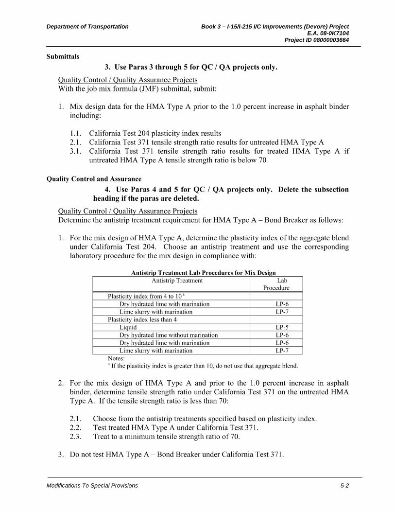
Department of Transportation Book 3 – I-15/I-215 I/C Improvements (Devore) Project E.A. 08-0K7104 Project ID 08000003664
Modifications To Special Provisions 5-2
Submittals
3. Use Paras 3 through 5 for QC / QA projects only.
Quality Control / Quality Assurance Projects With the job mix formula (JMF) submittal, submit: 1. Mix design data for the HMA Type A prior to the 1.0 percent increase in asphalt binder
including:
1.1. California Test 204 plasticity index results 2.1. California Test 371 tensile strength ratio results for untreated HMA Type A 3.1. California Test 371 tensile strength ratio results for treated HMA Type A if
untreated HMA Type A tensile strength ratio is below 70
Quality Control and Assurance
4. Use Paras 4 and 5 for QC / QA projects only. Delete the subsection heading if the paras are deleted.
Quality Control / Quality Assurance Projects Determine the antistrip treatment requirement for HMA Type A – Bond Breaker as follows: 1. For the mix design of HMA Type A, determine the plasticity index of the aggregate blend
under California Test 204. Choose an antistrip treatment and use the corresponding laboratory procedure for the mix design in compliance with:
Antistrip Treatment Lab Procedures for Mix Design
Antistrip Treatment Lab Procedure
Plasticity index from 4 to 10 a Dry hydrated lime with marination LP-6 Lime slurry with marination LP-7
Plasticity index less than 4 Liquid LP-5 Dry hydrated lime without marination LP-6 Dry hydrated lime with marination LP-6 Lime slurry with marination LP-7
Notes: a If the plasticity index is greater than 10, do not use that aggregate blend.
2. For the mix design of HMA Type A and prior to the 1.0 percent increase in asphalt
binder, determine tensile strength ratio under California Test 371 on the untreated HMA Type A. If the tensile strength ratio is less than 70:
2.1. Choose from the antistrip treatments specified based on plasticity index. 2.2. Test treated HMA Type A under California Test 371. 2.3. Treat to a minimum tensile strength ratio of 70.
3. Do not test HMA Type A – Bond Breaker under California Test 371.
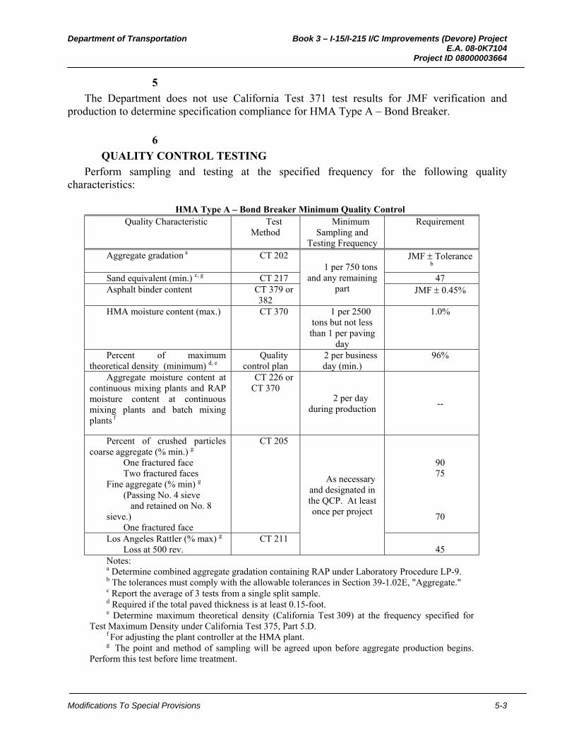
Department of Transportation Book 3 – I-15/I-215 I/C Improvements (Devore) Project E.A. 08-0K7104 Project ID 08000003664
Modifications To Special Provisions 5-3
5
The Department does not use California Test 371 test results for JMF verification and production to determine specification compliance for HMA Type A – Bond Breaker.
6
QUALITY CONTROL TESTING
Perform sampling and testing at the specified frequency for the following quality characteristics:
HMA Type A – Bond Breaker Minimum Quality Control
Quality Characteristic Test Method
Minimum Sampling and
Testing Frequency
Requirement
Aggregate gradation a CT 202 1 per 750 tons
and any remaining part
JMF Toleranceb
Sand equivalent (min.) c, g CT 217 47 Asphalt binder content CT 379 or
382 JMF 0.45%
HMA moisture content (max.) CT 370 1 per 2500 tons but not less than 1 per paving
day
1.0%
Percent of maximum theoretical density (minimum) d, e
Quality control plan
2 per business day (min.)
96%
Aggregate moisture content at continuous mixing plants and RAP moisture content at continuous mixing plants and batch mixing plants f
CT 226 or CT 370
2 per day during production
--
Percent of crushed particles coarse aggregate (% min.) g
One fractured face Two fractured faces
Fine aggregate (% min) g
(Passing No. 4 sieve and retained on No. 8
sieve.) One fractured face
CT 205
As necessary and designated in the QCP. At least once per project
90 75
70
Los Angeles Rattler (% max) g
Loss at 500 rev. CT 211
45 Notes: a Determine combined aggregate gradation containing RAP under Laboratory Procedure LP-9. b The tolerances must comply with the allowable tolerances in Section 39-1.02E, "Aggregate." c Report the average of 3 tests from a single split sample.d Required if the total paved thickness is at least 0.15-foot. e Determine maximum theoretical density (California Test 309) at the frequency specified for
Test Maximum Density under California Test 375, Part 5.D. f For adjusting the plant controller at the HMA plant.g The point and method of sampling will be agreed upon before aggregate production begins.
Perform this test before lime treatment.

Department of Transportation Book 3 – I-15/I-215 I/C Improvements (Devore) Project E.A. 08-0K7104 Project ID 08000003664
Modifications To Special Provisions 5-4
7
Apply white pigmented curing compound to the finished surface of the HMA Type A (Bond Breaker) within 2 days of placing the portland cement concrete pavement. Pigmented curing compound must conform to the requirements of ASTM Designation C 309, Type 2, Class A. Curing compound must be applied in 2 separate applications to the area to be surfaced with portland cement concrete pavement. Apply curing compound at the rate of 1 gallon per 150 square feet.
8
ENGINEER'S ACCEPTANCE
The Engineer samples for acceptance testing, and tests for:
HMA Type A – Bond Breaker Acceptance Quality Characteristic Test Method Requirement
Aggregate gradation a CT 202 JMF Tolerance b
Sand equivalent (min.) c, f CT 217 47 Asphalt binder content CT 379 or 382 JMF 0.45% HMA moisture content (max.) CT 370 1.0% Percent of maximum theoretical density
(minimum) d, e Quality control
plan 96%
Percent of crushed particles coarse aggregate (% min.) f
One fractured face Two fractured faces
Fine aggregate (% min) f (Passing No. 4 sieve and retained on No. 8 sieve.) One fractured face
CT 205 90 75
70
Los Angeles Rattler (% max.) f Loss at 500 rev.
CT 211 45
Notes: a The Engineer determines combined aggregate gradation containing RAP under
Laboratory Procedure LP-9. b The tolerances must comply with the allowable tolerances in Section 39-1.02E,
"Aggregate." c The Engineer reports the average of 3 tests from a single split sample.d Required if the total paved thickness is at least 0.15-foot. e The Engineer determines maximum theoretical density (California Test 309) at the
frequency specified for Test Maximum Density under California Test 375, Part 5.D. f. The point and method of sampling will be agreed upon before aggregate production
begins. Perform this test before lime treatment.
MATERIALS
9 Asphalt Binder
The grade of asphalt binder mixed with aggregate for HMA Type A - Bond Breaker must be PG 64-16.
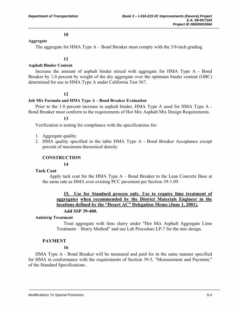
Department of Transportation Book 3 – I-15/I-215 I/C Improvements (Devore) Project E.A. 08-0K7104 Project ID 08000003664
Modifications To Special Provisions 5-5
10 Aggregate
The aggregate for HMA Type A – Bond Breaker must comply with the 3/8-inch grading.
11 Asphalt Binder Content
Increase the amount of asphalt binder mixed with aggregate for HMA Type A - Bond Breaker by 1.0 percent by weight of the dry aggregate over the optimum binder content (OBC) determined for use in HMA Type A under California Test 367.
12 Job Mix Formula and HMA Type A – Bond Breaker Evaluation
Prior to the 1.0 percent increase in asphalt binder, HMA Type A used for HMA Type A - Bond Breaker must conform to the requirements of Hot Mix Asphalt Mix Design Requirements.
13
Verification is testing for compliance with the specifications for: 1. Aggregate quality 2. HMA quality specified in the table HMA Type A - Bond Breaker Acceptance except
percent of maximum theoretical density
CONSTRUCTION
14
Tack Coat Apply tack coat for the HMA Type A – Bond Breaker to the Lean Concrete Base at
the same rate as HMA over existing PCC pavement per Section 39-1.09.
15. Use for Standard process only. Use to require lime treatment of aggregates when recommended by the District Materials Engineer in the locations defined by the “Desert AC” Delegation Memo (June 1, 2001).
Add SSP 39-400. Antistrip Treatment
Treat aggregate with lime slurry under "Hot Mix Asphalt Aggregate Lime Treatment – Slurry Method” and use Lab Procedure LP-7 for the mix design.
PAYMENT
16
HMA Type A - Bond Breaker will be measured and paid for in the same manner specified for HMA in conformance with the requirements of Section 39-5, "Measurement and Payment," of the Standard Specifications.
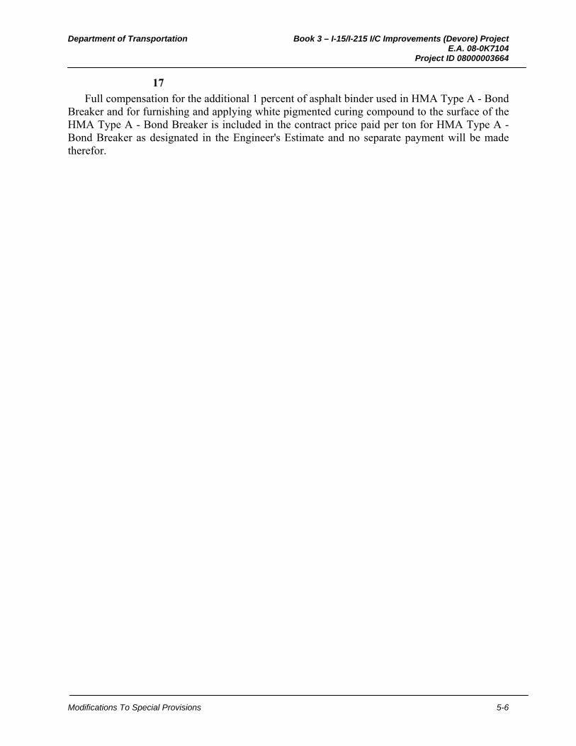
Department of Transportation Book 3 – I-15/I-215 I/C Improvements (Devore) Project E.A. 08-0K7104 Project ID 08000003664
Modifications To Special Provisions 5-6
17
Full compensation for the additional 1 percent of asphalt binder used in HMA Type A - Bond Breaker and for furnishing and applying white pigmented curing compound to the surface of the HMA Type A - Bond Breaker is included in the contract price paid per ton for HMA Type A - Bond Breaker as designated in the Engineer's Estimate and no separate payment will be made therefor.

Department of Transportation Book 3 – I-15/I-215 I/C Improvements (Devore) Project E.A. 08-0K7104 Project ID 08000003664
Modifications To Special Provisions 5-1
3. HOT MIX ASPHALT (TYPE C)
39-728_E_D06-05-09 Page 1 of 15
Use in District 8 projects only. Obtain approval from the Division of Pavement Management for editing beyond the instructions of this District SSP .
Use with amended Section 39, "Hot Mix Asphalt." Edit in plain language.
Use for projects that require high stability hot mix asphalt (HMA Type C). Use with concurrence of the District Materials Engineer or the District Pavement Engineer.
HMA Type C is intended for use where rutting is a concern including intersections, ramps, climbing lanes, and weigh stations.
Use the following pavement thicknesses for each gradation size of HMA Type C:
Grading Specified Total Thickness Range 1/2 - inch 0.15 foot – 0.25 foot 3/4 - inch 0.25 foot and above 1 - inch 0.35 foot and above
Use the Quality Control / Quality Assurance (QC / QA) process on projects with at least 10,000 tons of HMA Type C.
Use the Method process on projects with less than 250 tons of HMA Type C per location.
Use the Standard process on projects that do not meet the criteria for QC / QA and Method processes.
For projects using the QC / QA process, include SSP 39-400, "Lime Treatment of Hot Mix Asphalt Aggregate - Slurry Method," SSP 39-450, "Lime Treatment of Hot Mix Asphalt Aggregate - Dry Lime Method," and SSP 39-500, "Liquid Antistrip Treatment."
For projects using the Standard or Method process, the District Materials Engineer (DME) may recommend lime treatment of aggregates in the locations defined by the “Desert AC” Delegation Memo (June 1, 2001).
BEES item codes possibly triggered by this SSP are:
390129 Hot Mix Asphalt (Type C)
390135 Hot Mix Asphalt (Leveling)
397005 Tack Coat
394060 Data Core
395000 Prime Coat
Use other HMA item codes required by the plans or other SSPs (e.g., RHMA, OGFC, dike, rumble strips, etc.)
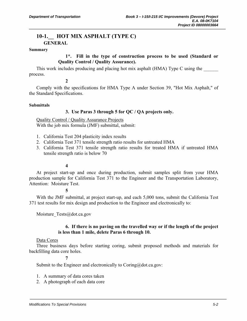
Department of Transportation Book 3 – I-15/I-215 I/C Improvements (Devore) Project E.A. 08-0K7104 Project ID 08000003664
Modifications To Special Provisions 5-2
10-1.__ HOT MIX ASPHALT (TYPE C) GENERAL
Summary
1*. Fill in the type of construction process to be used (Standard or Quality Control / Quality Assurance).
This work includes producing and placing hot mix asphalt (HMA) Type C using the ______ process.
2
Comply with the specifications for HMA Type A under Section 39, "Hot Mix Asphalt," of the Standard Specifications.
Submittals
3. Use Paras 3 through 5 for QC / QA projects only.
Quality Control / Quality Assurance Projects With the job mix formula (JMF) submittal, submit: 1. California Test 204 plasticity index results 2. California Test 371 tensile strength ratio results for untreated HMA 3. California Test 371 tensile strength ratio results for treated HMA if untreated HMA
tensile strength ratio is below 70
4
At project start-up and once during production, submit samples split from your HMA production sample for California Test 371 to the Engineer and the Transportation Laboratory, Attention: Moisture Test.
5
With the JMF submittal, at project start-up, and each 5,000 tons, submit the California Test 371 test results for mix design and production to the Engineer and electronically to:
6. If there is no paving on the travelled way or if the length of the project is less than 1 mile, delete Paras 6 through 10.
Data Cores Three business days before starting coring, submit proposed methods and materials for
backfilling data core holes.
7
Submit to the Engineer and electronically to [email protected]: 1. A summary of data cores taken 2. A photograph of each data core
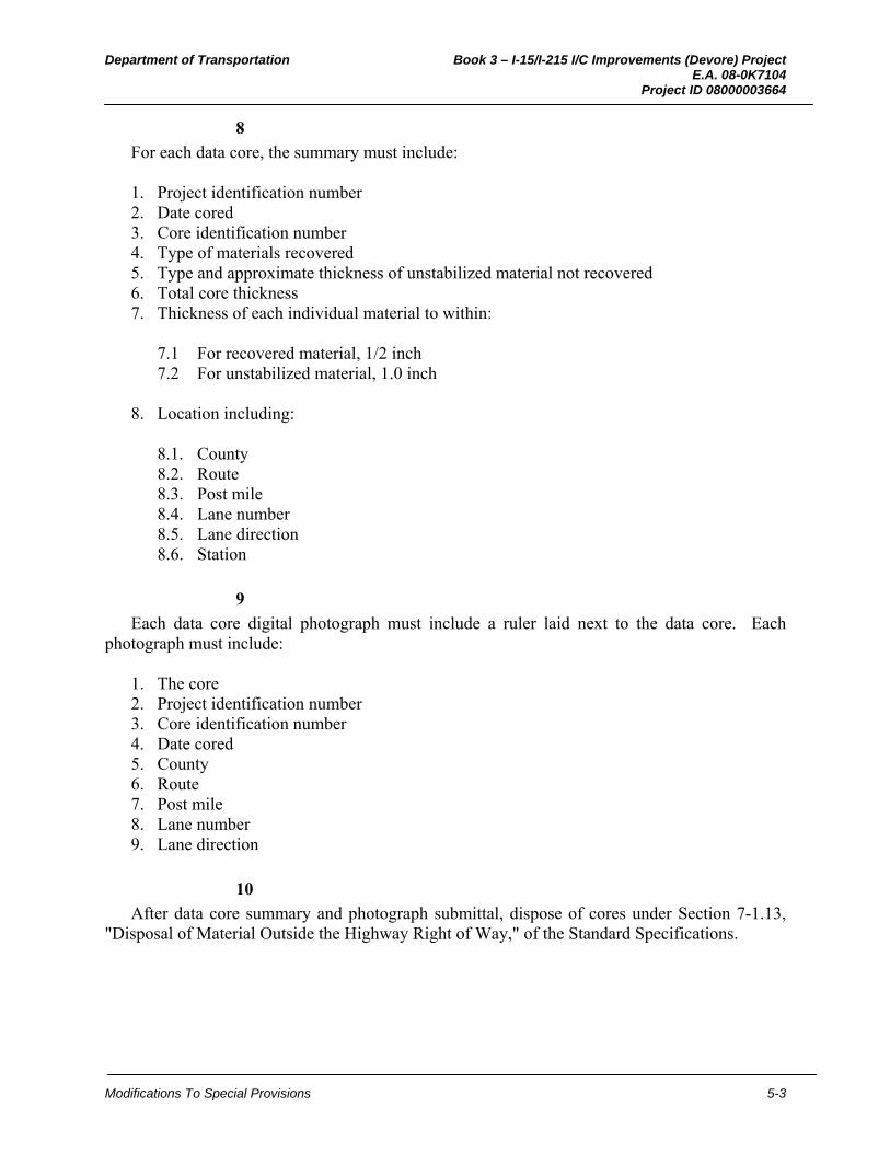
Department of Transportation Book 3 – I-15/I-215 I/C Improvements (Devore) Project E.A. 08-0K7104 Project ID 08000003664
Modifications To Special Provisions 5-3
8
For each data core, the summary must include: 1. Project identification number 2. Date cored 3. Core identification number 4. Type of materials recovered 5. Type and approximate thickness of unstabilized material not recovered 6. Total core thickness 7. Thickness of each individual material to within:
7.1 For recovered material, 1/2 inch 7.2 For unstabilized material, 1.0 inch
8. Location including:
8.1. County 8.2. Route 8.3. Post mile 8.4. Lane number 8.5. Lane direction 8.6. Station
9
Each data core digital photograph must include a ruler laid next to the data core. Each photograph must include:
1. The core 2. Project identification number 3. Core identification number 4. Date cored 5. County 6. Route 7. Post mile 8. Lane number 9. Lane direction
10
After data core summary and photograph submittal, dispose of cores under Section 7-1.13, "Disposal of Material Outside the Highway Right of Way," of the Standard Specifications.

Department of Transportation Book 3 – I-15/I-215 I/C Improvements (Devore) Project E.A. 08-0K7104 Project ID 08000003664
Modifications To Special Provisions 5-4
11. Use Paras 11 through 14 for QC / QA projects only. Delete the subsection heading, "Quality Control / Quality Assurance Projects," if the paras are deleted.
Quality Control and Assurance
Quality Control / Quality Assurance Projects For the mix design, determine the plasticity index of the aggregate blend under California
Test 204. Choose an antistrip treatment and use the corresponding laboratory procedure for the mix design in compliance with:
Antistrip Treatment Lab Procedures for Mix Design
Antistrip Treatment Lab Procedure
Plasticity index from 4 to 10 a Dry hydrated lime with marination LP-6 Lime slurry with marination LP-7
Plasticity index less than 4 Liquid LP-5 Dry hydrated lime without marination LP-6 Dry hydrated lime with marination LP-6 Lime slurry with marination LP-7
Notes: a If the plasticity index is greater than 10, do not use that aggregate blend.
12
For the mix design, determine tensile strength ratio under California Test 371 on untreated HMA. If the tensile strength ratio is less than 70:
1. Choose from the antistrip treatments specified based on plasticity index. 2. Test treated HMA under California Test 371. 3. Treat to a minimum tensile strength ratio of 70.
13
On the first production day and at least every 5,000 tons, sample HMA and test under California Test 371.
14
The Department does not use California Test 371 test results for JMF verification and production to determine specification compliance.
15. Use if the Standard construction process is specified, otherwise delete.
Take 3 density cores for every 250 tons of HMA Type C from random locations the Engineer designates.
16
With the minimum quality control testing for the specified construction process, perform sampling and testing at the specified frequency for the following quality characteristics:
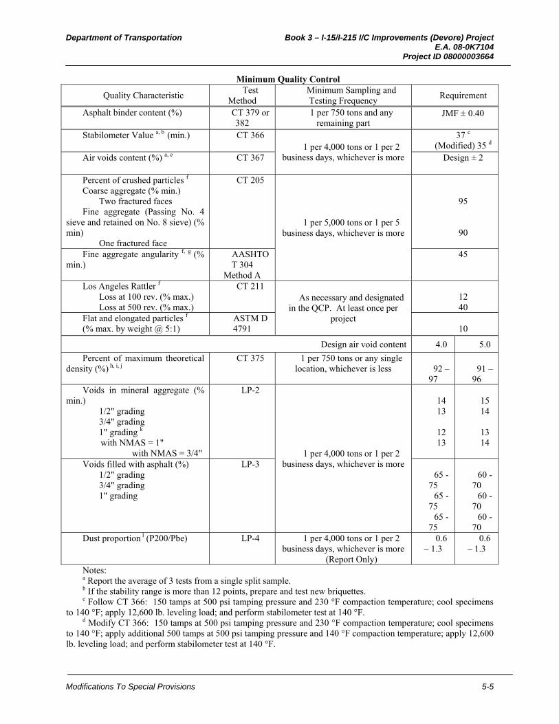
Department of Transportation Book 3 – I-15/I-215 I/C Improvements (Devore) Project E.A. 08-0K7104 Project ID 08000003664
Modifications To Special Provisions 5-5
Minimum Quality Control
Quality Characteristic Test
Method Minimum Sampling and Testing Frequency
Requirement
Asphalt binder content (%) CT 379 or 382
1 per 750 tons and any remaining part
JMF 0.40
Stabilometer Value a, b (min.) CT 366 1 per 4,000 tons or 1 per 2
business days, whichever is more
37 c (Modified) 35 d
Air voids content (%) a, e CT 367 Design ± 2
Percent of crushed particles f
Coarse aggregate (% min.) Two fractured faces
Fine aggregate (Passing No. 4 sieve and retained on No. 8 sieve) (% min)
One fractured face
CT 205
1 per 5,000 tons or 1 per 5 business days, whichever is more
95
90
Fine aggregate angularity f, g (% min.)
AASHTO T 304
Method A
45
Los Angeles Rattler f Loss at 100 rev. (% max.) Loss at 500 rev. (% max.)
CT 211 As necessary and designated
in the QCP. At least once per project
12 40
Flat and elongated particles f (% max. by weight @ 5:1)
ASTM D 4791
10
Design air void content 4.0 5.0
Percent of maximum theoretical density (%) h, i, j
CT 375 1 per 750 tons or any single location, whichever is less
92 –
97
91 –
96 Voids in mineral aggregate (%
min.) 1/2" grading 3/4" grading 1" grading k with NMAS = 1" with NMAS = 3/4"
LP-2
1 per 4,000 tons or 1 per 2 business days, whichever is more
14 13
12 13
15 14
13 14
Voids filled with asphalt (%) 1/2" grading 3/4" grading 1" grading
LP-3 65 -
75 65 -
75 65 -
75
60 -
70 60 -
70 60 -
70 Dust proportion l (P200/Pbe) LP-4 1 per 4,000 tons or 1 per 2
business days, whichever is more (Report Only)
0.6 – 1.3
0.6 – 1.3
Notes: a Report the average of 3 tests from a single split sample.b If the stability range is more than 12 points, prepare and test new briquettes. c Follow CT 366: 150 tamps at 500 psi tamping pressure and 230 °F compaction temperature; cool specimens
to 140 °F; apply 12,600 lb. leveling load; and perform stabilometer test at 140 °F. d Modify CT 366: 150 tamps at 500 psi tamping pressure and 230 °F compaction temperature; cool specimens
to 140 °F; apply additional 500 tamps at 500 psi tamping pressure and 140 °F compaction temperature; apply 12,600 lb. leveling load; and perform stabilometer test at 140 °F.

Department of Transportation Book 3 – I-15/I-215 I/C Improvements (Devore) Project E.A. 08-0K7104 Project ID 08000003664
Modifications To Special Provisions 5-6
e Determine the bulk specific gravity of each lab-compacted briquette under CT 308, Method A. Determine theoretical maximum specific gravity under CT 309. Calculate the air voids content of each specimen using CT 309 and LP 1. Modify CT 367, Paragraph C5, to use the design air voids content specified under "Hot Mix Asphalt Type C Mixture."
f Aggregate must comply with the quality specifications before it is treated with lime. During lime treatment except for dry lime on damp aggregate treatment at continuous mixing plants, sample coarse and fine aggregate from individual stockpiles. Combine aggregate in the JMF proportions. Prepare and test 3 samples from a single split sample for aggregate quality at the frequency specified during lime treatment and report test results as the average of the 3 tests.
g Void if HMA contains less than 10 percent of nonmanufactured sand by weight of total aggregate. Manufactured sand is fine aggregate produced by crushing rock or gravel.
h Required if the specified paved thickness is at least 0.15 foot. i Determine maximum theoretical density (California Test 309) at the frequency specified for Test Maximum
Density under California Test 375, Part 5.D. j For Standard process, take and average 3 cores per 250 tons of HMA placed k Minimum VMA dependent upon NMAS of JMF. NMAS is defined as one sieve size larger than the first
sieve to retain more than 10 percent. l Asphalt content based on dry weight of aggregate .
17
With the acceptance testing for the specified construction process, the Engineer samples and tests the following quality characteristics:
HMA Type C Acceptance
Quality Characteristic Test Method Requirement Asphalt binder content (%) CT 379 or 382 JMF 0.40
Stabilometer Value a, b, (min.) CT 366 37 c (Modified) 35 d
Air voids content (%) a, e CT 367 Design ± 2 Percent of crushed particles f
Coarse aggregate (% min.) Two fractured faces
Fine aggregate (Passing No. 4 sieve and retained on No. 8 sieve) (% min)
One fractured face
CT 205
95
90 Fine aggregate angularity f, g (% min.) AASHTO T 304
Method A 45
Los Angeles Rattler f Loss at 100 rev. (% max.) Loss at 500 rev. (% max.)
CT 211 12 40
Flat and elongated particles f (% max. by weight @ 5:1)
ASTM D 4791 10
Design air void content 4.0 5.0 Percent of maximum theoretical density (%) h,
i, j CT 375 92 –
97 91 – 96
Voids in mineral aggregate (% min.) 1/2" grading 3/4" grading 1" grading k with NMAS = 1" with NMAS = 3/4"
LP-2 14 13
12 13
15 14
13 14

Department of Transportation Book 3 – I-15/I-215 I/C Improvements (Devore) Project E.A. 08-0K7104 Project ID 08000003664
Modifications To Special Provisions 5-7
Voids filled with asphalt (%) 1/2" grading 3/4" grading 1" grading
LP-3 65 -
75 65 -
75 65 -
75
60 - 70 60 - 70 60 - 70
Dust proportion l(P200/Pbe) LP-4 0.6 – 1.3 Report Only
Notes: a The Engineer reports the average of 3 tests from a single split sample.b If the stability range is more than 12 points, the Engineer prepares and tests new briquettes. c The Engineer follows CT 366: 150 tamps at 500 psi tamping pressure and 230 °F compaction
temperature; cool specimens to 140 °F; apply 12,600 lb. leveling load; and perform stabilometer test at 140 °F.
d Modify CT 366: 150 tamps at 500 psi tamping pressure and 230 °F compaction temperature; cool specimens to 140 °F; apply additional 500 tamps at 500 psi tamping pressure and 140 °F compaction temperature; apply 12,600 lb. leveling load; and perform stabilometer test at 140 °F.
e The Engineer determines the bulk specific gravity of each lab-compacted briquette under CT 308, Method A. The Engineer determines theoretical maximum specific gravity under CT 309. The Engineer calculates the air voids content of each specimen using CT 309 and LP 1. The Engineer modifies CT 367, Paragraph C5, to use the design air voids content specified under "Hot Mix Asphalt Type C Mixture."
f Aggregate must comply with the quality specifications before it is treated with lime. During lime treatment, except for dry lime on damp aggregate treatment at continuous mixing plants; the Engineer samples coarse and fine aggregate from individual stockpiles, combines aggregate in the JMF proportions, and prepares and tests 3 samples from a single split sample for aggregate quality at the frequency specified during lime treatment and report test results as the average of the 3 tests.
g Void if HMA contains less than 10 percent of nonmanufactured sand by weight of total aggregate. Manufactured sand is fine aggregate produced by crushing rock or gravel.
h Required if the specified paved thickness is at least 0.15 foot.i Determine maximum theoretical density (California Test 309) at the frequency specified for Test
Maximum Density under California Test 375, Part 5.D. j For Standard process, take and average 3 cores per 250 tons of HMA placed. k Minimum VMA dependent upon NMAS of JMF. NMAS is defined as one sieve size larger than the
first sieve to retain more than 10 percent. l Asphalt content based on dry weight of aggregate.
18
The Engineer tests the 3 density cores you take from each 250 tons of HMA production. The Engineer determines the percent of maximum theoretical density for each density core by determining the density core's density and dividing by the maximum theoretical density. The Engineer determines the percent of maximum theoretical density for each 250 tons of HMA production by determining the average of the 3 density cores.
19
If the specified total paved thickness is at least 0.15 foot and any layer is less than 0.15 foot, the Engineer determines the percent of maximum theoretical density from density cores taken from the final layer measured the full depth of the total paved HMA.

Department of Transportation Book 3 – I-15/I-215 I/C Improvements (Devore) Project E.A. 08-0K7104 Project ID 08000003664
Modifications To Special Provisions 5-8
20. Use if the Standard construction process is specified and air voids content is 4%. Delete para 21 if using this para.
For each 250 tons of HMA production, the Engineer determines a deduction for percent of maximum theoretical density for each average of 3 density cores if it is outside the specifications, as follows:
Reduced Payment Factors for Percent of Maximum Theoretical Density
HMA Type C Percent of
Maximum Theoretical Density
Reduced Payment Factor
HMA Type C Percent of
Maximum Theoretical Density
Reduced Payment Factor
92.0 0.0000 97.0 0.0000 91.9 0.0125 97.1 0.0125 91.8 0.0250 97.2 0.0250 91.7 0.0375 97.3 0.0375 91.6 0.0500 97.4 0.0500 91.5 0.0625 97.5 0.0625 91.4 0.0750 97.6 0.0750 91.3 0.0875 97.7 0.0875 91.2 0.1000 97.8 0.1000 91.1 0.1125 97.9 0.1125 91.0 0.1250 98.0 0.1250 90.9 0.1375 98.1 0.1375 90.8 0.1500 98.2 0.1500 90.7 0.1625 98.3 0.1625 90.6 0.1750 98.4 0.1750 90.5 0.1875 98.5 0.1875 90.4 0.2000 98.6 0.2000 90.3 0.2125 98.7 0.2125 90.2 0.2250 98.8 0.2250 90.1 0.2375 98.9 0.2375 90.0 0.2500 99.0 0.2500
< 90.0 Remove and Replace > 99.0
Remove and Replace
21. Use if the Standard construction process is specified and air voids content is 5%. Delete para 20 if using this para.
For each 250 tons of HMA production, the Engineer determines a deduction for percent of maximum theoretical density for each average of 3 density cores if it is outside the specifications, as follows:

Department of Transportation Book 3 – I-15/I-215 I/C Improvements (Devore) Project E.A. 08-0K7104 Project ID 08000003664
Modifications To Special Provisions 5-9
Reduced Payment Factors for Percent of Maximum Theoretical Density HMA Type A
and B and RHMA-G Percent of Maximum Theoretical Density
Reduced Payment Factor
HMA Type A and B and RHMA-G Percent of Maximum Theoretical Density
Reduced Payment Factor
91.0 0.0000 96.0 0.0000 90.9 0.0125 96.1 0.0125 90.8 0.0250 96.2 0.0250 90.7 0.0375 96.3 0.0375 90.6 0.0500 96.4 0.0500 90.5 0.0625 96.5 0.0625 90.4 0.0750 96.6 0.0750 90.3 0.0875 96.7 0.0875 90.2 0.1000 96.8 0.1000 90.1 0.1125 96.9 0.1125 90.0 0.1250 97.0 0.1250 89.9 0.1375 97.1 0.1375 89.8 0.1500 97.2 0.1500 89.7 0.1625 97.3 0.1625 89.6 0.1750 97.4 0.1750 89.5 0.1875 97.5 0.1875 89.4 0.2000 97.6 0.2000 89.3 0.2125 97.7 0.2125 89.2 0.2250 97.8 0.2250 89.1 0.2375 97.9 0.2375 89.0 0.2500 98.0 0.2500
< 89.0 Remove and Replace > 98.0
Remove and Replace
22. Use if chain wear may be a concern.
HMA must comply with the following quality requirement when mixed with the asphalt used on the project in the amount determined to be optimum by California Test 367:
Quality
Characteristic Test Requirement
Surface Abrasion CT 360 Loss not to exceed 0.4 g/cm2
MATERIALS
Asphalt Binder
23*. Fill in the asphalt binder grade (use only PG 64-28 PM, PG 70-10, or PG 76-22 PM). Consult with the District Materials Engineer.
The grade of asphalt binder mixed with aggregate for HMA Type C must be ___________.
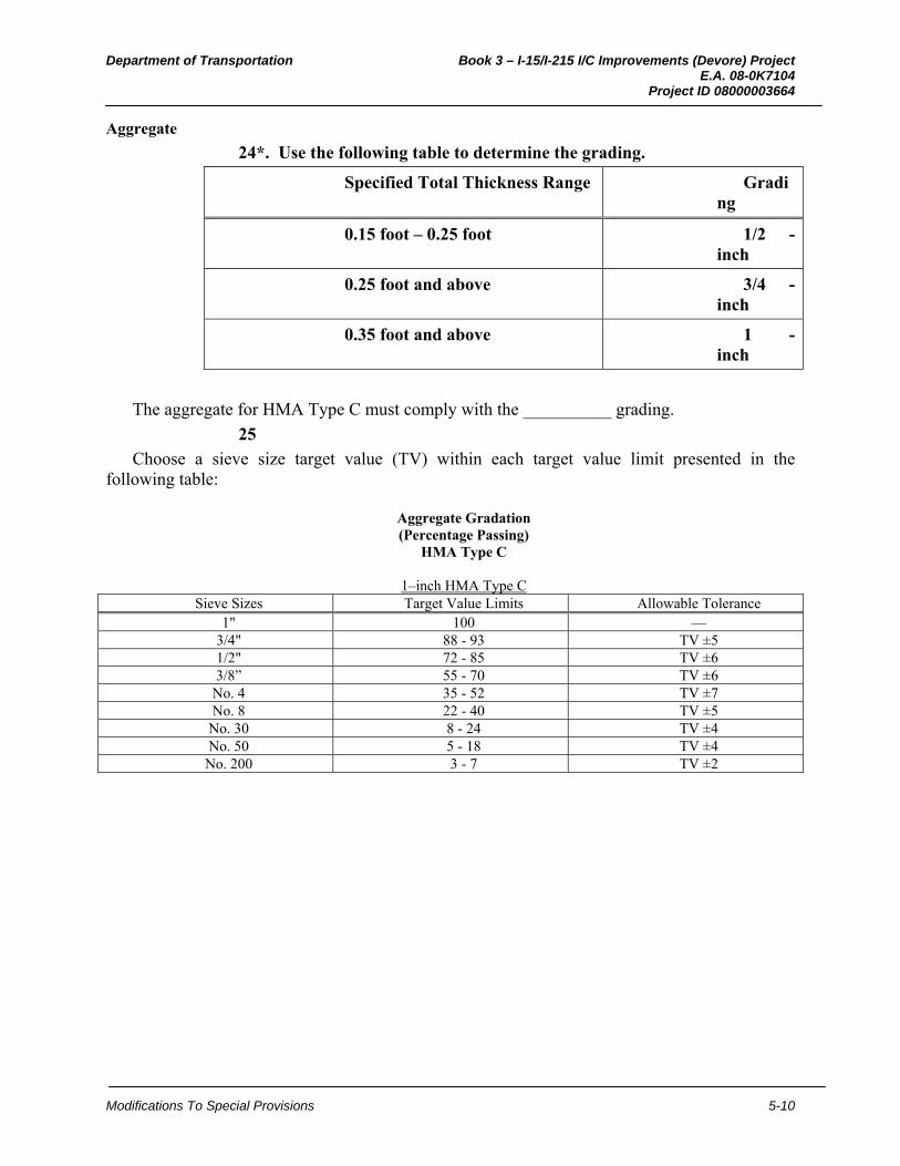
Department of Transportation Book 3 – I-15/I-215 I/C Improvements (Devore) Project E.A. 08-0K7104 Project ID 08000003664
Modifications To Special Provisions 5-10
Aggregate
24*. Use the following table to determine the grading.
Specified Total Thickness Range Grading
0.15 foot – 0.25 foot 1/2 - inch
0.25 foot and above 3/4 - inch
0.35 foot and above 1 - inch
The aggregate for HMA Type C must comply with the __________ grading.
25
Choose a sieve size target value (TV) within each target value limit presented in the following table:
Aggregate Gradation (Percentage Passing)
HMA Type C
1–inch HMA Type C Sieve Sizes Target Value Limits Allowable Tolerance
1" 100 — 3/4" 88 - 93 TV ±5 1/2" 72 - 85 TV ±6 3/8” 55 - 70 TV ±6 No. 4 35 - 52 TV ±7 No. 8 22 - 40 TV ±5
No. 30 8 - 24 TV ±4 No. 50 5 - 18 TV ±4
No. 200 3 - 7 TV ±2
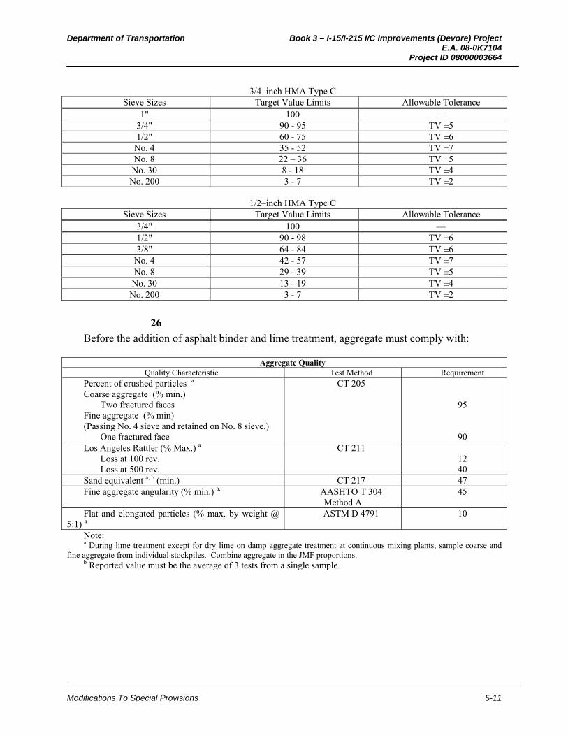
Department of Transportation Book 3 – I-15/I-215 I/C Improvements (Devore) Project E.A. 08-0K7104 Project ID 08000003664
Modifications To Special Provisions 5-11
3/4–inch HMA Type C
Sieve Sizes Target Value Limits Allowable Tolerance 1" 100 —
3/4" 90 - 95 TV ±5 1/2" 60 - 75 TV ±6
No. 4 35 - 52 TV ±7 No. 8 22 – 36 TV ±5
No. 30 8 - 18 TV ±4 No. 200 3 - 7 TV ±2
1/2–inch HMA Type C
Sieve Sizes Target Value Limits Allowable Tolerance 3/4" 100 — 1/2" 90 - 98 TV ±6 3/8" 64 - 84 TV ±6
No. 4 42 - 57 TV ±7 No. 8 29 - 39 TV ±5
No. 30 13 - 19 TV ±4 No. 200 3 - 7 TV ±2
26
Before the addition of asphalt binder and lime treatment, aggregate must comply with:
Aggregate QualityQuality Characteristic Test Method Requirement
Percent of crushed particles a
Coarse aggregate (% min.) Two fractured faces
Fine aggregate (% min) (Passing No. 4 sieve and retained on No. 8 sieve.)
One fractured face
CT 205
95
90 Los Angeles Rattler (% Max.) a
Loss at 100 rev. Loss at 500 rev.
CT 211 12 40
Sand equivalent a, b (min.) CT 217 47 Fine aggregate angularity (% min.) a, AASHTO T 304
Method A 45
Flat and elongated particles (% max. by weight @ 5:1) a
ASTM D 4791 10
Note: a During lime treatment except for dry lime on damp aggregate treatment at continuous mixing plants, sample coarse and
fine aggregate from individual stockpiles. Combine aggregate in the JMF proportions.b Reported value must be the average of 3 tests from a single sample.

Department of Transportation Book 3 – I-15/I-215 I/C Improvements (Devore) Project E.A. 08-0K7104 Project ID 08000003664
Modifications To Special Provisions 5-12
Hot Mix Asphalt Type C Mixture
27*. Insert the percent air voids. Determine percent air voids based on the following table:
Location Mountain
Valley Coast Desert
Traveled way & Shoulders 4.0 5.0 4.0 5.0 Intersections and ramp
termini 4.0 5.0 4.0 5.0
During mix design, determine the optimum binder content (OBC) at ___ percent air voids content.
28
Determine the proposed JMF from a mix design that complies with:
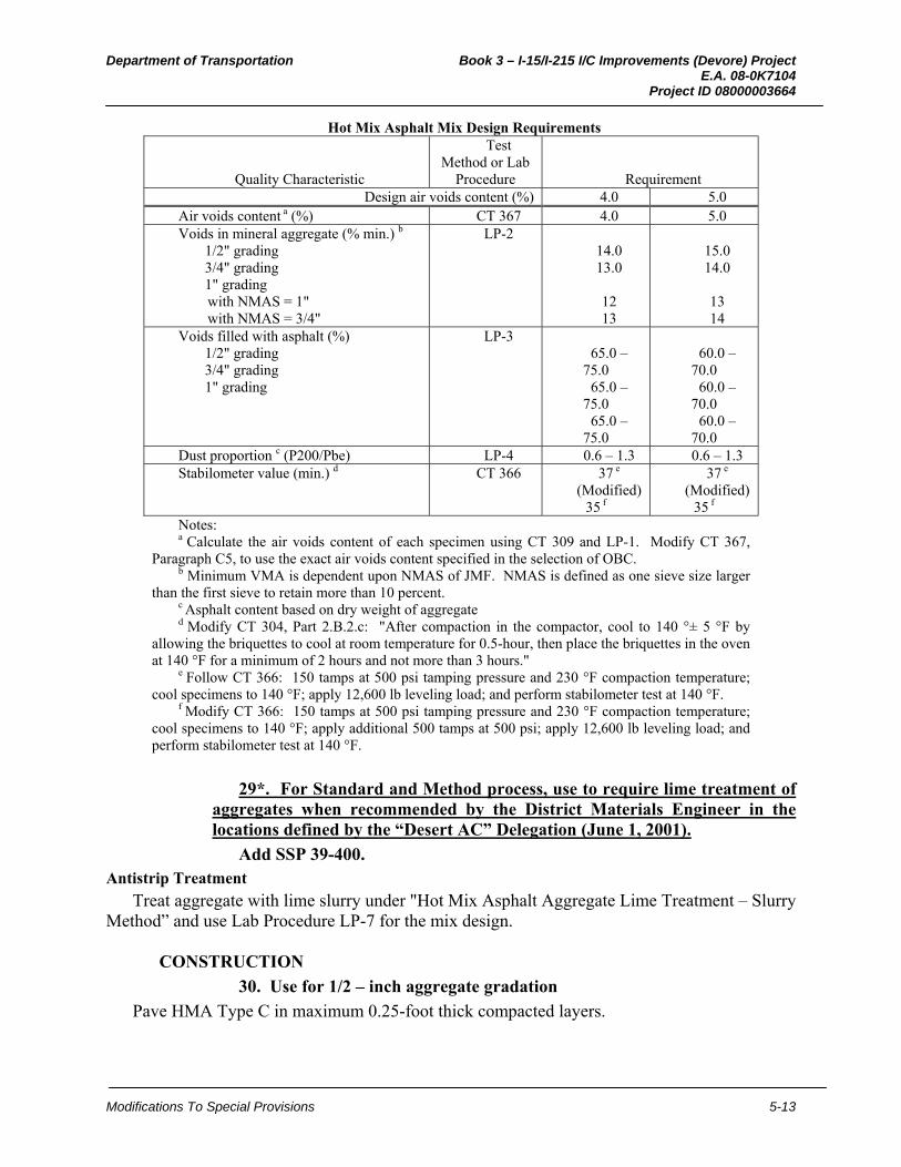
Department of Transportation Book 3 – I-15/I-215 I/C Improvements (Devore) Project E.A. 08-0K7104 Project ID 08000003664
Modifications To Special Provisions 5-13
Hot Mix Asphalt Mix Design Requirements
Quality Characteristic
Test Method or Lab
Procedure Requirement Design air voids content (%) 4.0 5.0
Air voids content a (%) CT 367 4.0 5.0 Voids in mineral aggregate (% min.) b
1/2" grading 3/4" grading 1" grading with NMAS = 1" with NMAS = 3/4"
LP-2 14.0 13.0
12 13
15.0 14.0
13 14
Voids filled with asphalt (%) 1/2" grading 3/4" grading 1" grading
LP-3 65.0 –
75.0 65.0 –
75.0 65.0 –
75.0
60.0 –
70.0 60.0 –
70.0 60.0 –
70.0 Dust proportion c (P200/Pbe) LP-4 0.6 – 1.3 0.6 – 1.3 Stabilometer value (min.) d CT 366 37 e
(Modified) 35 f
37 e
(Modified) 35 f
Notes: a Calculate the air voids content of each specimen using CT 309 and LP-1. Modify CT 367,
Paragraph C5, to use the exact air voids content specified in the selection of OBC. b Minimum VMA is dependent upon NMAS of JMF. NMAS is defined as one sieve size larger
than the first sieve to retain more than 10 percent. c Asphalt content based on dry weight of aggregate d Modify CT 304, Part 2.B.2.c: "After compaction in the compactor, cool to 140 °± 5 °F by
allowing the briquettes to cool at room temperature for 0.5-hour, then place the briquettes in the oven at 140 °F for a minimum of 2 hours and not more than 3 hours."
e Follow CT 366: 150 tamps at 500 psi tamping pressure and 230 °F compaction temperature; cool specimens to 140 °F; apply 12,600 lb leveling load; and perform stabilometer test at 140 °F.
f Modify CT 366: 150 tamps at 500 psi tamping pressure and 230 °F compaction temperature; cool specimens to 140 °F; apply additional 500 tamps at 500 psi; apply 12,600 lb leveling load; and perform stabilometer test at 140 °F.
29*. For Standard and Method process, use to require lime treatment of aggregates when recommended by the District Materials Engineer in the locations defined by the “Desert AC” Delegation (June 1, 2001).
Add SSP 39-400. Antistrip Treatment
Treat aggregate with lime slurry under "Hot Mix Asphalt Aggregate Lime Treatment – Slurry Method” and use Lab Procedure LP-7 for the mix design.
CONSTRUCTION
30. Use for 1/2 – inch aggregate gradation
Pave HMA Type C in maximum 0.25-foot thick compacted layers.
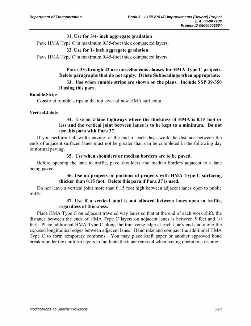
Department of Transportation Book 3 – I-15/I-215 I/C Improvements (Devore) Project E.A. 08-0K7104 Project ID 08000003664
Modifications To Special Provisions 5-14
31. Use for 3/4- inch aggregate gradation
Pave HMA Type C in maximum 0.35-foot thick compacted layers.
32. Use for 1- inch aggregate gradation
Pave HMA Type C in maximum 0.45-foot thick compacted layers.
Paras 33 through 42 are miscellaneous clauses for HMA Type C projects. Delete paragraphs that do not apply. Delete Subheadings when appropriate.
33. Use when rumble strips are shown on the plans. Include SSP 39-350 if using this para.
Rumble Strips
Construct rumble strips in the top layer of new HMA surfacing.
Vertical Joints
34. Use on 2-lane highways where the thickness of HMA is 0.15 foot or less and the vertical joint between lanes is to be kept to a minimum. Do not use this para with Para 37.
If you perform half-width paving, at the end of each day's work the distance between the ends of adjacent surfaced lanes must not be greater than can be completed in the following day of normal paving.
35. Use when shoulders or median borders are to be paved.
Before opening the lane to traffic, pave shoulders and median borders adjacent to a lane being paved.
36. Use on projects or portions of projects with HMA Type C surfacing thicker than 0.15 foot. Delete this para if Para 37 is used.
Do not leave a vertical joint more than 0.15 foot high between adjacent lanes open to public traffic.
37. Use if a vertical joint is not allowed between lanes open to traffic, regardless of thickness.
Place HMA Type C on adjacent traveled way lanes so that at the end of each work shift, the distance between the ends of HMA Type C layers on adjacent lanes is between 5 feet and 10 feet. Place additional HMA Type C along the transverse edge at each lane's end and along the exposed longitudinal edges between adjacent lanes. Hand rake and compact the additional HMA Type C to form temporary conforms. You may place kraft paper or another approved bond breaker under the conform tapers to facilitate the taper removal when paving operations resume.
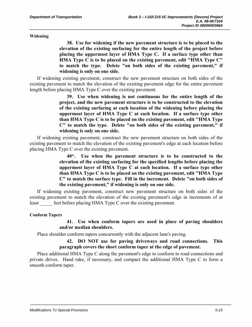
Department of Transportation Book 3 – I-15/I-215 I/C Improvements (Devore) Project E.A. 08-0K7104 Project ID 08000003664
Modifications To Special Provisions 5-15
Widening
38. Use for widening if the new pavement structure is to be placed to the elevation of the existing surfacing for the entire length of the project before placing the uppermost layer of HMA Type C. If a surface type other than HMA Type C is to be placed on the existing pavement, edit "HMA Type C" to match the type. Delete "on both sides of the existing pavement," if widening is only on one side.
If widening existing pavement, construct the new pavement structure on both sides of the existing pavement to match the elevation of the existing pavement edge for the entire pavement length before placing HMA Type C over the existing pavement.
39. Use when widening is not continuous for the entire length of the project, and the new pavement structure is to be constructed to the elevation of the existing surfacing at each location of the widening before placing the uppermost layer of HMA Type C at each location. If a surface type other than HMA Type C is to be placed on the existing pavement, edit "HMA Type C" to match the type. Delete "on both sides of the existing pavement," if widening is only on one side.
If widening existing pavement, construct the new pavement structure on both sides of the existing pavement to match the elevation of the existing pavement's edge at each location before placing HMA Type C over the existing pavement.
40*. Use when the pavement structure is to be constructed to the elevation of the existing surfacing for the specified lengths before placing the uppermost layer of HMA Type C at each location. If a surface type other than HMA Type C is to be placed on the existing pavement, edit "HMA Type C" to match the surface type. Fill in the increment. Delete "on both sides of the existing pavement," if widening is only on one side.
If widening existing pavement, construct new pavement structure on both sides of the existing pavement to match the elevation of the existing pavement's edge in increments of at least _____ feet before placing HMA Type C over the existing pavement.
Conform Tapers
41. Use when conform tapers are used in place of paving shoulders and/or median shoulders.
Place shoulder conform tapers concurrently with the adjacent lane's paving.
42. DO NOT use for paving driveways and road connections. This paragraph covers the short conform taper at the edge of pavement.
Place additional HMA Type C along the pavement's edge to conform to road connections and private drives. Hand rake, if necessary, and compact the additional HMA Type C to form a smooth conform taper.
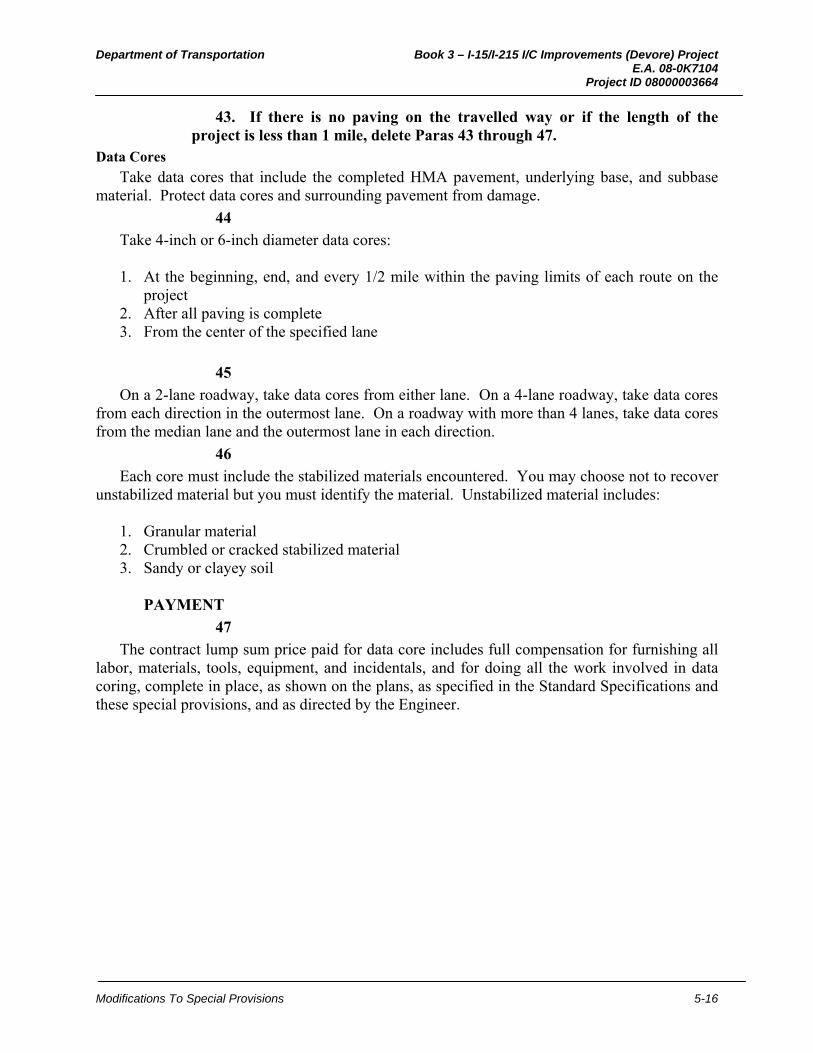
Department of Transportation Book 3 – I-15/I-215 I/C Improvements (Devore) Project E.A. 08-0K7104 Project ID 08000003664
Modifications To Special Provisions 5-16
43. If there is no paving on the travelled way or if the length of the project is less than 1 mile, delete Paras 43 through 47.
Data Cores
Take data cores that include the completed HMA pavement, underlying base, and subbase material. Protect data cores and surrounding pavement from damage.
44
Take 4-inch or 6-inch diameter data cores: 1. At the beginning, end, and every 1/2 mile within the paving limits of each route on the
project 2. After all paving is complete 3. From the center of the specified lane
45
On a 2-lane roadway, take data cores from either lane. On a 4-lane roadway, take data cores from each direction in the outermost lane. On a roadway with more than 4 lanes, take data cores from the median lane and the outermost lane in each direction.
46
Each core must include the stabilized materials encountered. You may choose not to recover unstabilized material but you must identify the material. Unstabilized material includes:
1. Granular material 2. Crumbled or cracked stabilized material 3. Sandy or clayey soil
PAYMENT
47
The contract lump sum price paid for data core includes full compensation for furnishing all labor, materials, tools, equipment, and incidentals, and for doing all the work involved in data coring, complete in place, as shown on the plans, as specified in the Standard Specifications and these special provisions, and as directed by the Engineer.

Department of Transportation Book 3 – I-15/I-215 I/C Improvements (Devore) Project E.A. 08-0K7104 Project ID 08000003664
Modifications To Special Provisions 5-1
4. JOINTED PLAIN CONCRETE PAVEMENT (RAPID STRENGTH CONCRETE) New nSSP Approved for use on EA XXXXXX by XXXXXX on XXXXX 40-JPCPRSC_ N12-22-11_nSSP Page 1 of 25
Edit in plain language.
This nSSP requires written approval from HQ Pavement Program, Office of Concrete Pavement and Pavement Foundations to use. Include drawings indicating where and how this spec will be used including title sheet, typical sections, layouts, construction details, quantity and any other sheets where details for this product are found. Please limit edits to those in the instructions. Additional edits will require substantiation as to why they are necessary and may require providing documentation to demonstrate that because of claims, special conditions, or other reasons modified language is necessary. Please plan on 2 weeks for review if spec is only edited as per contained instructions and at least 4 weeks if additional edits are made.
Use for new construction and/or lane replacement of jointed plain concrete pavement with rapid strength concrete. Do not use this nSSP for slab replacement. Slab replacement is defined as replacing individual concrete slabs within an existing concrete pavement to the same thickness as existing. Lane replacement and new construction involves placing concrete pavement within defined limits (e.g. between bridges, ramp termini, bridge approaches, etc.) and must meet the design standards and traffic loads for new construction of pavements as defined in the Highway Design Manual Chapter 610 and 620. Provide station limits on the plans where new construction and/or lane replacement with rapid strength concrete will be used.
Provide adequate number of working days to cover the time required for the Contractor to determine concrete mix proportions as specified in Section 40 of the Standard Specifications. Factor in the delayed start time if using SSP S4-003 (used for projects over $5 million and 200 working days under a 2-year pilot program). METS - Rigid Pavement & Structural Concrete Unit estimates 90 days is required before starting concrete pavement work.
District Materials Engineer and District Maintenance should recommend a joint seal type. Select one joint seal type from silicone, asphalt rubber, or compression seal.
Include dowel bars, tie bars and baskets in SSP S5-250 for partial payment of materials on hand.
Use BEES Item Codes:
401050A Jointed Plain Concrete Pavement (Rapid Strength Concrete)
401050B Jointed Plain Concrete Pavement (Ramp Termini with Rapid Strength Concrete) if ramp termini are part of the project.
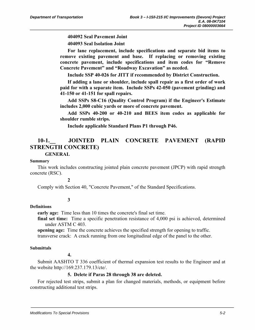
Department of Transportation Book 3 – I-15/I-215 I/C Improvements (Devore) Project E.A. 08-0K7104 Project ID 08000003664
Modifications To Special Provisions 5-2
404092 Seal Pavement Joint
404093 Seal Isolation Joint
For lane replacement, include specifications and separate bid items to remove existing pavement and base. If replacing or removing existing concrete pavement, include specifications and item codes for “Remove Concrete Pavement” and “Roadway Excavation” as needed.
Include SSP 40-026 for JITT if recommended by District Construction.
If adding a lane or shoulder, include spall repair as a first order of work paid for with a separate item. Include SSPs 42-050 (pavement grinding) and 41-150 or 41-151 for spall repairs.
Add SSPs S8-C16 (Quality Control Program) if the Engineer's Estimate includes 2,000 cubic yards or more of concrete pavement.
Add SSPs 40-200 or 40-210 and BEES item codes as applicable for shoulder rumble strips.
Include applicable Standard Plans P1 through P46.
10-1.__ JOINTED PLAIN CONCRETE PAVEMENT (RAPID STRENGTH CONCRETE)
GENERAL Summary
This work includes constructing jointed plain concrete pavement (JPCP) with rapid strength concrete (RSC).
2
Comply with Section 40, "Concrete Pavement," of the Standard Specifications.
3 Definitions
early age: Time less than 10 times the concrete's final set time. final set time: Time a specific penetration resistance of 4,000 psi is achieved, determined
under ASTM C 403. opening age: Time the concrete achieves the specified strength for opening to traffic. transverse crack: A crack running from one longitudinal edge of the panel to the other.
Submittals
4.
Submit AASHTO T 336 coefficient of thermal expansion test results to the Engineer and at the website http://169.237.179.13/cte/.
5. Delete if Paras 28 through 38 are deleted.
For rejected test strips, submit a plan for changed materials, methods, or equipment before constructing additional test strips.
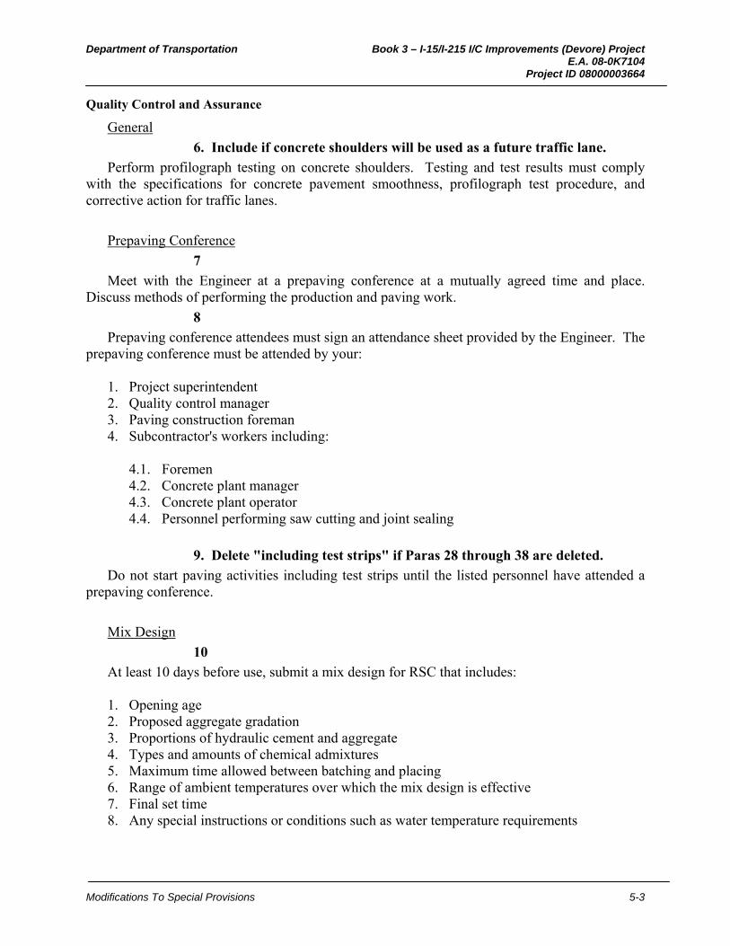
Department of Transportation Book 3 – I-15/I-215 I/C Improvements (Devore) Project E.A. 08-0K7104 Project ID 08000003664
Modifications To Special Provisions 5-3
Quality Control and Assurance
General
6. Include if concrete shoulders will be used as a future traffic lane.
Perform profilograph testing on concrete shoulders. Testing and test results must comply with the specifications for concrete pavement smoothness, profilograph test procedure, and corrective action for traffic lanes.
Prepaving Conference
7
Meet with the Engineer at a prepaving conference at a mutually agreed time and place. Discuss methods of performing the production and paving work.
8
Prepaving conference attendees must sign an attendance sheet provided by the Engineer. The prepaving conference must be attended by your:
1. Project superintendent 2. Quality control manager 3. Paving construction foreman 4. Subcontractor's workers including:
4.1. Foremen 4.2. Concrete plant manager 4.3. Concrete plant operator 4.4. Personnel performing saw cutting and joint sealing
9. Delete "including test strips" if Paras 28 through 38 are deleted.
Do not start paving activities including test strips until the listed personnel have attended a prepaving conference.
Mix Design
10
At least 10 days before use, submit a mix design for RSC that includes: 1. Opening age 2. Proposed aggregate gradation 3. Proportions of hydraulic cement and aggregate 4. Types and amounts of chemical admixtures 5. Maximum time allowed between batching and placing 6. Range of ambient temperatures over which the mix design is effective 7. Final set time 8. Any special instructions or conditions such as water temperature requirements

Department of Transportation Book 3 – I-15/I-215 I/C Improvements (Devore) Project E.A. 08-0K7104 Project ID 08000003664
Modifications To Special Provisions 5-4
11
Submit more than 1 mix design to plan for ambient temperature variations anticipated during RSC placement. Each mix design must have a maximum ambient temperature range of 18 °F.
12
Submit modulus of rupture development data for each mix design. You may use modulus of rupture development data from laboratory-prepared samples. The testing ages for modulus of rupture development data must include 1 hour before opening age, opening age, one hour after opening age, 24 hours, 7 days, and 28 days.
12a
During concrete mix design, perform coefficient of thermal expansion testing under AASHTO T 336 from trial mixture samples. Provide a split test sample to METS. If changing an aggregate supply source or the mix properties or proportions, perform coefficient of thermal expansion testing for the new concrete mix.
Calibration Testing Certificates of Compliance
13
Submit a Certificate of Compliance under Section 6-1.07, "Certificates of Compliance," of the Standard Specifications with each delivery of aggregate, cement, and admixtures to be used for calibration tests. Submit certified copies of the weight of each delivery. The Certificate of Compliance must state the source of materials used for the calibration tests is from the same source to be used in the work. The Certificate of Compliance must be signed by your authorized representative.
Cement and Admixtures
14. Do not edit the number of days without approval from district materials laboratory and METS, Office of Structural Materials.
At least 45 days before intended use, submit a sample of cement from each proposed lot and samples of proposed admixtures in the quantities ordered by the Engineer.
15
During RSC pavement operations, submit uniformity reports for hydraulic cement at least once every 30 days to the Transportation Laboratory, Attention: Cement Laboratory. Uniformity reports must comply with ASTM C 917, except testing age and water content may be modified to suit the particular material.
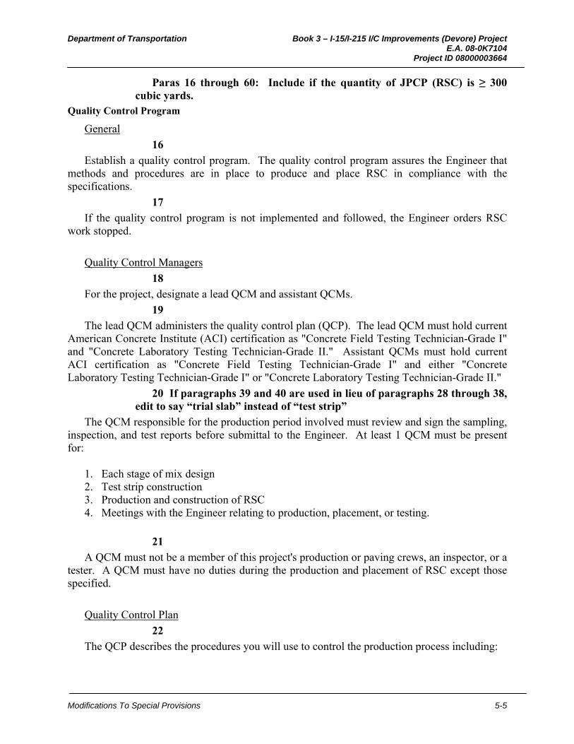
Department of Transportation Book 3 – I-15/I-215 I/C Improvements (Devore) Project E.A. 08-0K7104 Project ID 08000003664
Modifications To Special Provisions 5-5
Paras 16 through 60: Include if the quantity of JPCP (RSC) is ≥ 300 cubic yards.
Quality Control Program
General
16
Establish a quality control program. The quality control program assures the Engineer that methods and procedures are in place to produce and place RSC in compliance with the specifications.
17
If the quality control program is not implemented and followed, the Engineer orders RSC work stopped.
Quality Control Managers
18
For the project, designate a lead QCM and assistant QCMs.
19
The lead QCM administers the quality control plan (QCP). The lead QCM must hold current American Concrete Institute (ACI) certification as "Concrete Field Testing Technician-Grade I" and "Concrete Laboratory Testing Technician-Grade II." Assistant QCMs must hold current ACI certification as "Concrete Field Testing Technician-Grade I" and either "Concrete Laboratory Testing Technician-Grade I" or "Concrete Laboratory Testing Technician-Grade II."
20 If paragraphs 39 and 40 are used in lieu of paragraphs 28 through 38, edit to say “trial slab” instead of “test strip”
The QCM responsible for the production period involved must review and sign the sampling, inspection, and test reports before submittal to the Engineer. At least 1 QCM must be present for:
1. Each stage of mix design 2. Test strip construction 3. Production and construction of RSC 4. Meetings with the Engineer relating to production, placement, or testing.
21
A QCM must not be a member of this project's production or paving crews, an inspector, or a tester. A QCM must have no duties during the production and placement of RSC except those specified.
Quality Control Plan
22
The QCP describes the procedures you will use to control the production process including:
Department of Transportation Book 3 – I-15/I-215 I/C Improvements (Devore) Project E.A. 08-0K7104 Project ID 08000003664
Modifications To Special Provisions 5-6
1. Determining if changes to the production process are needed 2. Procedures for proposing changes 3. Procedures for implementing changes
23 If paragraphs 39 and 40 are used in lieu of paragraphs 28 through 38, edit to say “trial slab” instead of “test strip”
Do not start RSC work until the QCP has been accepted by the Engineer. The Engineer accepts the QCP based the inclusion and adequacy of:
1. The names and qualifications of the lead Quality Control Manager (QCM) and assistant
QCMs. 2. An outline procedure for the placement and testing of test strips 3. An outline procedure for the production, transportation, and placement of RSC 4. An outline procedure for sampling and testing to be performed during and after RSC
construction 5. A contingency plan for correcting problems in production, transportation, or placement.
Include the quantity and location of standby material in your contingency plan. 6. Provisions for determining if RSC placement must be suspended and temporary roadway
pavement structure constructed 7. Forms to report inspection, sampling, and testing 8. The location of your quality control testing laboratory and testing equipment during and
after paving operations 9. A list of the testing equipment to be used including date of last calibration 10. The names and certifications of quality control personnel including those performing
sampling and testing
24
At the time of QCP submission, the Department qualifies the quality control samplers and testers through the Independent Assurance Program (IAP) for the sampling and testing they perform.
Quality Control Inspection, Sampling, and Testing
25
Perform quality control sampling, testing, and inspection throughout RSC production and placement. Before any sampling and testing, give the Engineer at least 2 business days notice. Give the Engineer unrestricted access to your quality control inspectors, samplers, testers, and laboratories. Submit testing results within 15 minutes of testing completion. Record inspection, sampling, and testing on the forms accepted with the QCP and submit them within 48 hours of completion of each paving shift and within 24 hours of 7-day modulus of rupture tests.
26
Provide a testing laboratory to perform quality control tests. Maintain sampling and testing equipment in proper working condition. Perform sampling under California Test 125.

Department of Transportation Book 3 – I-15/I-215 I/C Improvements (Devore) Project E.A. 08-0K7104 Project ID 08000003664
Modifications To Special Provisions 5-7
27
Testing laboratories and testing equipment must comply with the Department's Independent Assurance Program.
Delete Paras 28 through 38 if there is less than 2,000 cubic yards of jointed plain concrete pavement (rapid strength concrete) or no segment that is at least 700 feet in length on the project and delete the heading.
Test Strips
28
The first paving activity must be to construct a test strip: 1. 700 to 1,000 feet long 2. Same width as the planned paving 3. With the same equipment used for the planned paving
29
The Engineer evaluates the test strip for compliance with the specifications for Engineer's acceptance.
30
The Engineer selects from 6 to 12 core locations for dowel bars and up to 6 locations for tie bars per test strip.
31
If you use mechanical dowel bar inserters, the test strip must demonstrate they do not leave voids, segregations, or surface irregularities such as depressions, dips, or high areas.
32
Allow the Engineer 3 days to evaluate the test strip for: 1. Smoothness 2. Dowel bar and tie bar alignment 3. Thickness 4. Final finishing except coefficient of friction
33
During the 3-day evaluation, the Engineer rejects a test strip if: 1. Surface varies more than 0.02 foot from a 12-foot straightedge's lower edge 2. Wheel path's individual high points are greater than 0.025 foot in 25 feet 3. Dowel bars do not comply with specified placement tolerances 4. Concrete pavement thickness deficiency is greater than 0.05 foot 5. Final finishing does not comply with the specifications except coefficient of friction

Department of Transportation Book 3 – I-15/I-215 I/C Improvements (Devore) Project E.A. 08-0K7104 Project ID 08000003664
Modifications To Special Provisions 5-8
34
Remove the test strip if the Engineer rejects it for noncompliance with the specifications for dowel bar alignment or thickness. Dispose of rejected test strip material under Section 7-1.13, "Disposal of Material Outside the Highway Right of Way," of the Standard Specifications.
35
If the Engineer rejects the test strip for noncompliance with the smoothness or final finishing specifications except coefficient of friction, you may grind the test strip into compliance if you intend to leave it as part of the paving.
36
If the Engineer does not reject the test strip during the 3-day evaluation, you may begin production paving while the Engineer continues to evaluate the test strip for compliance with the other specifications. If the Engineer rejects the test strip for noncompliance with the other specifications, stop production paving until you construct a test strip the Engineer accepts.
37
Construct additional test strips until the Engineer accepts one.
38
Construct additional test strips if: 1. You propose different paving equipment including:
1.1. Batch plant 1.2. Paver 1.3. Dowel bar inserter 1.4. Tie bar inserter 1.5. Tining 1.6. Curing equipment
2. You change concrete mix proportions
Paras 39 through 40: Delete when paragraphs 28 through 38 are used. Trial Slabs
39
Before starting work on RSC, complete one trial slab for each rapid strength concrete mix design. Trial slabs demonstrate that you are capable of producing replacement concrete pavement in compliance with the specifications within the specified time periods including delivery, placement, finishing, and curing times, and under similar atmospheric and temperature conditions expected during replacement operations.
40
The trial slab must be at least 10' x 20'. The trial slab thickness must be at least 10 inches. Place trial slabs near the job site at a mutually-agreed location that is neither on the roadway nor within the project limits.
Department of Transportation Book 3 – I-15/I-215 I/C Improvements (Devore) Project E.A. 08-0K7104 Project ID 08000003664
Modifications To Special Provisions 5-9
If paragraphs 39 and 40 are used in lieu of paragraphs 28 through 38, edit paragraphs 41 through 47 to say “trial slab” instead of “test strip”
41.
During test strip construction, sample and split the aggregate for gradings, cleanness value, and sand equivalent testing.
42.
Test strip must comply with the QCP for RSC production and placement. The QCP must detail your intended:
1. Locations and times 2. Production procedures 3. Placement and finishing methods 4. Sampling methods, sample curing, and sample transportation 5. Testing and test result reporting
43
Within 20 minutes after rapid strength concrete delivery for test strips, fabricate test beams under California Test 524. Use beams to determine early age and 7-day modulus of rupture values.
44
Cure beams fabricated for early age testing so that the monitored temperatures in the beams and the test strip are always within 5 °F. Monitor and record the internal temperatures of test strip and early age beams at intervals of at least 5 minutes. Install thermocouples or thermistors connected to strip-chart recorders or digital data loggers to monitor the temperatures. Temperature recording devices must be accurate to within ±2 ºF. Measure internal temperatures at 1 inch from the top, 1 inch from the bottom, and no closer than 3 inches from any edge until early age testing is completed.
45
Cure beams fabricated for 7-day testing under California Test 524 except place them into sand at a time that is from 5 to 10 times the final set time, or 24 hours, whichever is earlier.
46
Test strip must have an early age modulus of rupture of not less than 400 psi and a 7-day modulus of rupture of not less than 600 psi.
47
Dispose of test strip and test specimens for test strip under Section 7-1.13, "Disposal of Material Outside the Highway Right of Way," of the Standard Specifications.
Production Process Control and Quality Control Testing
48
Contingency plan equipment and personnel must be present at the job site.
Department of Transportation Book 3 – I-15/I-215 I/C Improvements (Devore) Project E.A. 08-0K7104 Project ID 08000003664
Modifications To Special Provisions 5-10
49
Provide continuous process control and quality control sampling and testing throughout RSC production and placement.
50
During production of RSC, sample and test aggregates at least once for every 650 cubic yards of RSC produced, but not less than once per placement shift. Test aggregates for compliance with gradations, cleanness value, and sand equivalent specifications.
51
At least once for every 650 cubic yards of RSC produced, but not less than twice per placement shift, sample and test for:
1. Yield 2. Penetration 3. Air content 4. Unit weight
52
During placement of RSC, fabricate beams and test for modulus of rupture within the first 30 cubic yards, at least once every 130 cubic yards, and within the final truckload.
53
If the Engineer requests, submit split samples and fabricate test beams for the Engineer's testing.
54
For determining early age modulus of rupture, cure beams under the same conditions as the pavement until 1 hour before testing. Cure beams fabricated for the 7-day test under California Test 524. The Engineer uses modulus of rupture test results for accepting or rejecting the replacement pavement and pay factor adjustment for low modulus of rupture.
55
Dispose of materials resulting from the construction of the test beams, temporary roadway pavement structure, and rejected replacement pavement under Section 7-1.13, "Disposal of Material Outside the Highway Right of Way," of the Standard Specifications.
Weighmaster Certificates
56
Weighmaster certificates for RSC, regardless of the proportioning method used, must include the information necessary to trace the manufacturer and the manufacturer's lot number for the cement being used. If proportioned into fabric containers, the weighmaster certificates for the cement must contain date of proportioning, location of proportioning, and actual net draft cement weight. If proportioned at the pour site from a storage silo, the weighmaster certificates must contain date of proportioning, location of proportioning, and the net draft cement weight used in the load.

Department of Transportation Book 3 – I-15/I-215 I/C Improvements (Devore) Project E.A. 08-0K7104 Project ID 08000003664
Modifications To Special Provisions 5-11
Engineer's Acceptance for Modulus of Rupture
57
RSC pavement must develop a minimum modulus of rupture of 400 psi before opening to traffic. RSC pavement must develop a minimum modulus of rupture of 600 psi 7 days after placement. The Engineer may accept RSC pavement that does not attain the specified moduli of rupture as specified in "Pay Factor Adjustment for Low Modulus of Rupture." You will determine the modulus of rupture by testing 3 beam specimens under California Test 524 and averaging the results in the presence of the Engineer. You may fabricate beam specimens using an internal vibrator under ASTM C 31. No single test represents more than that day's production or 130 cubic yards, whichever is less.
58
Beam specimens for early age must be cured so the temperature in the specimens is within 5 °F of the temperature in the pavement. You must determine the modulus of rupture at other ages using beams cured and tested under California Test 524 except place them in sand from 5 to 10 times the final set time or 24 hours, whichever is earlier. You must perform the testing to determine modulus of rupture values of the RSC pavement in the presence of the Engineer.
Pay Factor Adjustment for Low Modulus of Rupture
59
The Engineer adjusts payment for RSC for modulus of rupture as follows: 1. Payment for RSC with a modulus of rupture of 400 psi or greater before opening to
traffic and 7-day modulus of rupture of 600 psi or greater is not adjusted. 2. Payment for RSC with a 7-day modulus of rupture less than 500 psi is not adjusted and
no payment is made. Remove this RSC and replace it at your expense with RSC that complies with the specifications.
3. Payment for RSC with a modulus of rupture less than 350 psi before opening to traffic is not adjusted and no payment is made. Remove this RSC and replace it at your expense with RSC that complies with the specifications.
4. Payment for RSC with a modulus of rupture of 350 psi or greater before opening to traffic and a 7-day modulus of rupture greater than or equal to 500 psi is reduced by the percentage in the pay table for the quantity represented by the tests.
Percentage Pay Table
Modulus of Rupture (psi) at opening to traffic
7-Day Modulus of Rupture (psi) Greater
than or equal to 600
Less than 600 and greater
than or equal to 550
Less than 550 and greater
than or equal to 500
Greater than or equal to 400 100% 95% 90% Less than 400 and greater than or equal to 350
95% 95% 90%
Less than 350 0% 0% 0%
Department of Transportation Book 3 – I-15/I-215 I/C Improvements (Devore) Project E.A. 08-0K7104 Project ID 08000003664
Modifications To Special Provisions 5-12
60
The Engineer rejects any RSC area that develops 1 or more transverse full depth random cracks within 64 days after placement. Remove this RSC at your expense and replace it with RSC that complies with the specifications.
MATERIALS
Temporary Roadway Pavement Structure
Aggregate Base
61
Aggregate base for temporary roadway pavement structure must be produced from any combination of broken stone, crushed gravel, natural rough-surfaced gravel, reclaimed concrete and sand. Grading of aggregate base must comply with the 3/4-inch maximum grading specified in Section 26-1.02A, "Class 2 Aggregate Base," of the Standard Specifications.
Hot Mix Asphalt
62
For hot mix asphalt:
1. Choose the 3/8-inch or 1/2-inch HMA Type A or Type B aggregate gradation under Section 39-1.02E, "Aggregate," of the Standard Specifications.
2. Minimum asphalt binder content must be 6.8 percent for 3/8-inch aggregate gradation and 6.0 percent for 1/2-inch aggregate gradation.
3. Choose asphalt binder Grade PG 64-10, PG 64-16, or PG 70-10 under Section 92, "Asphalts," of the Standard Specifications.
Rapid Strength Concrete
63
RSC that fails to meet opening strength but has a modulus of rupture of at least 200 psi may serve as temporary roadway and must be replaced prior to acceptance of the contract.
Bond Breaker
64
Bond breaker must be one of the following: 1. White curing paper under ASTM C 171 2. White opaque polyethylene film under ASTM C 171, except that the minimum thickness
must be 6 mils 3. Paving asphalt, Grade PG 64-10, under Section 92, "Asphalts," of the Standard
Specifications 4. Curing compound (5) under Section 90-7.01b, "Curing Compound Method," of the
Standard Specifications
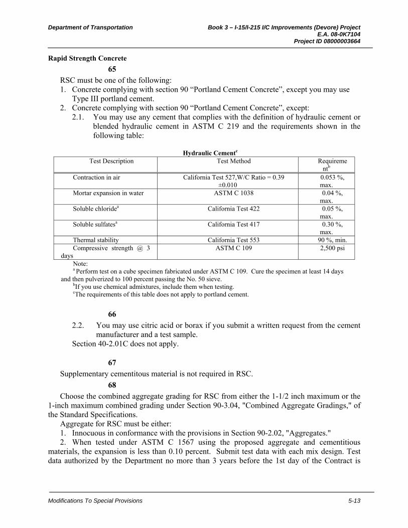
Department of Transportation Book 3 – I-15/I-215 I/C Improvements (Devore) Project E.A. 08-0K7104 Project ID 08000003664
Modifications To Special Provisions 5-13
Rapid Strength Concrete
65
RSC must be one of the following: 1. Concrete complying with section 90 “Portland Cement Concrete”, except you may use
Type III portland cement. 2. Concrete complying with section 90 “Portland Cement Concrete”, except:
2.1. You may use any cement that complies with the definition of hydraulic cement or blended hydraulic cement in ASTM C 219 and the requirements shown in the following table:
Hydraulic Cementc
Test Description Test Method Requirementb
Contraction in air California Test 527,W/C Ratio = 0.39 ±0.010
0.053 %, max.
Mortar expansion in water ASTM C 1038 0.04 %, max.
Soluble chloridea California Test 422 0.05 %, max.
Soluble sulfatesa California Test 417 0.30 %, max.
Thermal stability California Test 553 90 %, min. Compressive strength @ 3
days ASTM C 109 2,500 psi
Note: a Perform test on a cube specimen fabricated under ASTM C 109. Cure the specimen at least 14 days
and then pulverized to 100 percent passing the No. 50 sieve. bIf you use chemical admixtures, include them when testing. cThe requirements of this table does not apply to portland cement.
66
2.2. You may use citric acid or borax if you submit a written request from the cement manufacturer and a test sample.
Section 40-2.01C does not apply.
67
Supplementary cementitous material is not required in RSC.
68
Choose the combined aggregate grading for RSC from either the 1-1/2 inch maximum or the 1-inch maximum combined grading under Section 90-3.04, "Combined Aggregate Gradings," of the Standard Specifications.
Aggregate for RSC must be either: 1. Innocuous in conformance with the provisions in Section 90-2.02, "Aggregates." 2. When tested under ASTM C 1567 using the proposed aggregate and cementitious
materials, the expansion is less than 0.10 percent. Submit test data with each mix design. Test data authorized by the Department no more than 3 years before the 1st day of the Contract is
Department of Transportation Book 3 – I-15/I-215 I/C Improvements (Devore) Project E.A. 08-0K7104 Project ID 08000003664
Modifications To Special Provisions 5-14
authorized for the entire Contract. The test data must be for the same concrete mix and must use the same materials and material sources to be used on the Contract.
69
You may use Type C accelerating and Type E accelerating and water reducing chemical admixtures as specified in Section 90-4, "Admixtures," of the Standard Specifications. The requirement for air entrainment of concrete in freeze-thaw areas only applies when portland cement is used.
69A
During concrete mix design, perform coefficient of thermal expansion testing under AASHTO T 336 from trial mixture samples. If changing an aggregate supply source or the mix properties or proportions, perform coefficient of thermal expansion testing for the new concrete mix. This test will not be used for acceptance.
Bar Reinforcement
70. Use Paras 70 through 72 in the high desert climate region and the mountain climate regions or if pavement is placed within 1,000 feet of an ocean or other salt water body, otherwise delete and delete heading. Refer to the Pavement Climate Map on the Pavement website at:
http://www.dot.ca.gov/hq/oppd/pavement/Pavement_Climateregions_100505.pdf
Bar reinforcement must be one of the following: 1. Epoxy coated steel reinforcing bar:
1.1. Bar must comply with ASTM A 615/A 615M, Grade 40 or 60; ASTM A 996/A 996M; or ASTM A 706/A 706M.
1.2. Epoxy-coating must comply with ASTM A 934/A 934M. Epoxy-coating must be purple or gray and handled at the manufacturing plant and job site under ASTM D 3963/D 3963M and Section 52-1.02B, "Epoxy-coated Reinforcement," of the Standard Specifications.
2. Low carbon, chromium steel bar:
2.1. Low carbon, chromium steel bar must comply withASTM A 1035/A 1035 M.
Dowel Bar and Dowel Bar Baskets
71
Dowel bar and dowel bar baskets must be one of the following: 1. Epoxy coated steel reinforcing bar
1.1. Reinforcing bar must comply with ASTM A 615/A 615M, Grade 40 or 60. 1.2. Epoxy coating must comply with ASTM A 884/A 884M, Class A, Type 2. Epoxy
coating must be purple or gray.
2. Stainless steel bar:
Department of Transportation Book 3 – I-15/I-215 I/C Improvements (Devore) Project E.A. 08-0K7104 Project ID 08000003664
Modifications To Special Provisions 5-15
2.1. Stainless steel bar must be descaled, pickled, and polished solid stainless steel bars, UNS Designation S31603 or S31803, Grade 60 under ASTM A 276/A 276M, and ASTM A 955/A 955M.
2.2. If placed under the basket placing method, stainless steel baskets must comply with ASTM A 493/A 493M, UNS S31600 or S31603.
Tie Bar and Tie Bar Baskets
72
Tie bar and tie bar baskets must be one of the following: 1. Epoxy coated steel reinforcing bar:
1.1. Bar reinforcing must comply with ASTM A 615/A 615M, Grade 40 or 60; ASTM A 996/A 996M; or ASTM A 706/A 706M
1.2. Epoxy coating for deformed tie bars must comply with ASTM A 934/A 934M. Epoxy coating must be purple or gray.
1.3. Epoxy coating for smooth tie bars and tie bar baskets must comply with ASTM A 884/A 884M, Class A, Type 2.
2. Stainless steel bar:
2.1. Stainless steel bar must be descaled, pickled, and polished solid stainless steel bars UNS Designation S31603 or S31803, Grade 60 under ASTM A 955/A 955M. If placed under the basket placing method, baskets must be stainless steel under ASTM A 493/A 493M, UNS S31600 or S31603.
Liquid Joint Sealant
73*. Specify type(s) of joint (e.g., longitudinal contraction joint) and silicone or asphalt rubber sealant. Delete if only compression joint seals are specified and delete heading.
Liquid joint sealant for ___________________ must be __________________.
Liquid Joint Sealant for Isolation Joints
74*. Specify silicone or asphalt rubber sealant. Match the liquid joint sealant specified in Para 73. Do not use compression joint seals for isolation joints. Edit type, otherwise delete and delete heading.
Liquid joint sealant for isolation joints must be __________________.
Joint Seal
75*. Specify type(s) of joint (e.g., longitudinal, contraction joint). Delete if compression joint seals are not specified and delete heading.
Use compression seal for ______.

Department of Transportation Book 3 – I-15/I-215 I/C Improvements (Devore) Project E.A. 08-0K7104 Project ID 08000003664
Modifications To Special Provisions 5-16
Joint Filler for Isolation Joints
76*. Specify bituminous expansion joint filler, Type 1 preformed expansion joint filler or Type 2 performed expansion joint filler. Edit type, otherwise delete and delete heading.
Joint filler for isolation joints must be _______________________.
Tack Coat
77
Tack coat must comply with Section 39, "Hot Mix Asphalt," of the Standard Specifications.
CONSTRUCTION
Tie Bar Spacing On Curves
78
If the curvature of a concrete pavement slab prevents equal spacing of tie bars to maintain the minimum clearance from transverse joints, space them from 15 to 18 inches.
Transverse Contraction Joints
79*. Edit to specify type, otherwise delete and delete heading. Choose Type A1 or Type B. Edit consistent with Para 73.
Transverse contraction joints must be Type _____. If widening existing concrete pavement, do not construct transverse contraction joints to match the existing pavement's joint spacing or skew unless specified. Transverse joints in concrete pavement on a curve must be on a single straight line through the curve's radius point.
Longitudinal Contraction Joints
80*. Edit to specify type, otherwise delete and delete heading. Choose Type A2 or Type B. Edit consistent with Para 73.
Longitudinal contraction joints must be Type _____.
Transition Joints With Hot Mix Asphalt
81
If a joint between concrete pavement and hot mix asphalt is specified, apply tack coat between the concrete pavement and hot mix asphalt.
Temporary Roadway Pavement Structure
82
Place hot mix asphalt and aggregate base where existing pavement is replaced for construction of a temporary roadway pavement structure. The quantity must be equal to the quantity of pavement removed during the work shift. If you place temporary roadway pavement structure, it must be maintained and later removed as the first order of work when JPCP (RSC) activities resume. The temporary roadway pavement structure must consist of 3-1/2 inch thick

Department of Transportation Book 3 – I-15/I-215 I/C Improvements (Devore) Project E.A. 08-0K7104 Project ID 08000003664
Modifications To Special Provisions 5-17
hot mix asphalt over aggregate base. RSC not conforming to the specifications may be used for temporary roadway pavement structure with the Engineer's approval.
83
Spread and compact aggregate base and hot mix asphalt by methods that produce a well-compacted, uniform base, with a surface of uniform smoothness, texture and density. Surfaces must be free from pockets of coarse or fine material. You may spread aggregate base and hot mix asphalt each in one layer. The finished surface of hot mix asphalt must not vary more than 0.05 foot from the lower edge of a 12-foot long straightedge placed parallel with the centerline and must match the elevation of existing concrete pavement along the joints between the existing pavement and temporary surfacing.
84
After removing temporary roadway pavement structure, you may stockpile removed aggregate base at the project site and reuse it for temporary roadway pavement structures. When no longer required, dispose of standby material or stockpiled material for temporary roadway pavement structures under Section 7-1.13, "Disposal of Material Outside the Highway Right of Way," of the Standard Specifications.
Rapid Strength Concrete
General
85
Concrete pavement penetration specified in Section 90-6.06, "Amount of Water and Penetration," of the Standard Specifications does not apply to RSC.
86
RSC must develop the specified opening age and 7-day modulus of rupture strengths.
Proportioning
87
Weighing, measuring, and metering devices used for proportioning materials must comply with Section 9-1.01, "Measurement of Quantities," of the Standard Specifications.
88. Delete Item 4 if Paras 103 through 131 are deleted (volumetric proportioning).
For batches with a volume of 1 cubic yard or more, proportioning must comply with one of
the following methods: 1. Batch the ingredients at a central batch plant and charge them into a mixer truck for
transportation to the pour site. Proportion ingredients under Section 90-5, "Proportioning," of the Standard Specifications.
2. Batch the ingredients except the cement at a central batch plant and charge them into a mixer truck for transportation to a cement silo and weigh system, which must proportion cement for charging into the mixer truck.

Department of Transportation Book 3 – I-15/I-215 I/C Improvements (Devore) Project E.A. 08-0K7104 Project ID 08000003664
Modifications To Special Provisions 5-18
3. Batch ingredients except the cement at a central batch plant and charge them into a mixer truck for transportation to a location where pre-weighed containerized cement is added to the mixer truck. The cement pre-weighing operation must utilize a platform scale. The platform scale must have a maximum capacity of 2.75 tons with a maximum graduation size of 1 pound. Pre-weigh cement into a fabric container. The minimum amount of cement to be proportioned into any single container must be 1/2 of the total amount required for the load of RSC being produced.
4. Cement, water, and aggregate are proportioned volumetrically.
89
For central batch plants, indicators for weighing and measuring systems such as over and under dials must be grouped so that each indicator's smallest increment can be accurately read from the control point of the proportioning operation. In addition, indicators for weighing and measuring cement batched from a remote weighing system must be placed so that each indicator can be accurately read from the control point of the proportioning operation.
90
Weighing equipment must be insulated from other equipment's vibration or movement. When the plant is operating, each draft's material weight must not vary from the designated weight by more than the specified tolerances. Each scale graduation must be 0.001 of the usable scale capacity.
91
Aggregate must be weighed cumulatively. Equipment for weighing aggregate must have a zero tolerance of ±0.5 percent of the aggregate's designated total batch weight. Equipment for the separate weighing of the cement must have a zero tolerance of ±0.5 percent of the cement's designated individual batch draft. Equipment for measuring water must have a zero tolerance of ±0.5 percent of the water's designated weight or volume.
92
The weight indicated for any individual batch of material must not vary from the preselected scale setting by more than:
Batch Weight Tolerances
Material Tolerance Aggregate ±1.0 percent of designated batch weight Cement ±0.5 percent of designated batch weight Water ±1.5 percent of designated batch weight or
volume
93
Proportioning consists of dividing the aggregate into the specified sizes and storing them in separate bins, and then combining the aggregate with cement and water. Proportion dry ingredients by weight. Proportion liquid ingredients by weight or volume.
94
Handle and store aggregates under Section 90-5.01, "Storage of Aggregates," of the Standard Specifications. Proportion liquid admixtures under Section 90-4.10, "Proportioning and Dispensing Liquid Admixtures," of the Standard Specifications.
Department of Transportation Book 3 – I-15/I-215 I/C Improvements (Devore) Project E.A. 08-0K7104 Project ID 08000003664
Modifications To Special Provisions 5-19
95
Control aggregate discharged from several bins with gates or mechanical conveyors. The means of discharge from the bins and from the weigh hopper must be interlocked so that no more than 1 bin can discharge at a time, and the weigh hopper cannot be discharged until the required quantity from each of the bins has been deposited in the weigh hopper.
96
At the time of batching, dry and drain aggregates to a stable moisture content. Do not proportion aggregates with visible separation of water from the aggregate during proportioning. At the time of batching, the free moisture content of fine aggregate must not exceed 8 percent of its saturated, surface-dry weight.
97
If the proportioning plant has separate supplies of the same size group of aggregate with different moisture content, specific gravity, or surface characteristics affecting workability, exhaust 1 supply before using another supply.
98
Keep cement separated from the aggregate until discharged into the mixer. When discharged into the mixer, cement must be free of lumps and clods. Before reuse, clean fabric containers used for transportation or proportioning of cement.
99
Weigh systems for proportioning aggregate and cement must be individual and distinct from other weigh systems. Each weigh system must have a hopper, a lever system, and an indicator.
100
When ordered by the Engineer, determine the gross weight and tare weight of truck mixers on scales designated by the Engineer.
101
Install and maintain in operating condition an electrically actuated moisture meter. The meter must indicate on a readily visible scale the changes in the fine aggregate moisture content as it is batched. The meter must have a sensitivity of 0.5 percent by weight of the fine aggregate.
102
Obtain the Engineer's acceptance before mixing water into the concrete during hauling or after arrival at the delivery point. If the Engineer accepts additional water be incorporated into the concrete, the drum must revolve not less than 30 revolutions at mixing speed after the water is added and before starting discharge. Measure water added to the truck mixer at the job site through a meter in compliance with Section 9-1.01, "Measurement of Quantities," of the Standard Specifications.
Department of Transportation Book 3 – I-15/I-215 I/C Improvements (Devore) Project E.A. 08-0K7104 Project ID 08000003664
Modifications To Special Provisions 5-20
Paras 103 through 131: Delete unless "Volumetric Proportioning" is recommended by the District Materials Engineer and approved by District Construction. Discuss with District or Headquarters Weights and Measures Coordinator and METS, Office of Structural Materials.
Volumetric Proportioning
103
You may choose to proportion RSC by volume.
104
Handle and store aggregates under Section 90-5.01, "Storage of Aggregates," of the Standard Specifications. Proportion liquid admixtures under Section 90-4.10, "Proportioning and Dispensing Liquid Admixtures," of the Standard Specifications.
105
Batch-mixer trucks must proportion cement, water, aggregate, and additives by volume. Aggregate feeders must be connected directly to the drive on the cement vane feeder. The cement feed rate must be tied directly to the feed rate for the aggregate and other ingredients. Only change the ratio of cement to aggregate by changing the gate opening for the aggregate feed. The drive shaft of the aggregate feeder must have a revolution counter reading to the nearest full or partial revolution of the aggregate delivery belt.
106
Proportion aggregate with a belt feeder operated with an adjustable cutoff gate delineated to the nearest quarter increment. The gate opening height must be readily determinable. Proportion cement by any method that complies with the accuracy tolerance specifications. Proportion water with a meter under Section 9-1.01, "Measurement and Payment," of the Standard Specifications.
107
Calibrate the cutoff gate for each batch-mixer truck used and for each aggregate source. Calibrate batch-mixer trucks at 3 different aggregate gate settings that are commensurate with production needs. Perform at least 2 calibration runs for each aggregate gate.
108
Individual aggregate delivery rate check-runs must not deviate more than 1.0 percent from the mathematical average of all runs for the same gate and aggregate type. Each test run must be at least 1,000 pounds.
109
At the time of batching, dry and drain aggregates to a stable moisture content. Do not proportion aggregates with visible separation of water from the aggregate during proportioning. At the time of batching, the free moisture content of fine aggregate must not exceed 8 percent of its saturated, surface-dry weight.
110
If the proportioning plant has separate supplies of the same size group of aggregate with different moisture content, specific gravity, or surface characteristics affecting workability, exhaust 1 supply before using another supply.
Department of Transportation Book 3 – I-15/I-215 I/C Improvements (Devore) Project E.A. 08-0K7104 Project ID 08000003664
Modifications To Special Provisions 5-21
111
Cover rotating and reciprocating equipment on batch-mixer trucks with metal guards.
112
Individual cement delivery rate check-runs must not deviate more than 1.0 percent of the mathematical average of 3 runs of at least 1,000 pounds each.
113
When the water meter operates from 50 to 100 percent of production capacity, the indicated weight of water delivered must not differ from the actual weight delivered by more than 1.5 percent for each of 2 runs of 300 gallons. Calibrate the water meter under California Test 109. The water meter must be equipped with a resettable totalizer and display the operating rate.
114
Conduct calibration tests for aggregate, cement, and water proportioning devices with a platform scale located at the calibration site. Platform scales for weighing test-run calibration material must have a maximum capacity of 2.75 tons with maximum graduations of 1 pound. Error test the platform scale within 8 hours of calibrating the batch-mixer truck proportioning devices. Perform error-testing with test weights under California Test 109. Furnish a witness scale that is within 2 graduations of the test weight load. The witness scale must be available for use at the production site throughout the production period. Equipment needed for the calibration of proportioning systems must remain available at the production site throughout the production period.
115
The batch-mixer truck must be equipped so that accuracy checks can be made. Recalibrate proportioning devices every 30 days after production starts or when you change the source or type of any ingredient.
116
A spot calibration is calibration of the cement proportioning system only. Perform a 2-run spot calibration each time 55 tons of cement passes through the batch-mixer truck. If the spot calibration shows the cement proportioning system does not comply with the specifications, complete a full calibration of the cement proportioning system before you resume production.
117
Proportion liquid admixtures with a meter.
118
Locate cement storage immediately before the cement feeder. Equip the system with a device that automatically shuts down power to the cement feeder and aggregate belt feeder when the cement storage level is less than 20 percent of the total volume.
119
Submit aggregate moisture determinations, made under California Test 223, at least every 2 hours during proportioning and mixing operations. Record moisture determinations and submit them at the end of each production shift.

Department of Transportation Book 3 – I-15/I-215 I/C Improvements (Devore) Project E.A. 08-0K7104 Project ID 08000003664
Modifications To Special Provisions 5-22
120
Equip each aggregate bin with a device that automatically shuts down the power to the cement feeder and the aggregate belt feeder when the aggregate discharge rate is less than 95 percent of the scheduled discharge rate.
121
Proportioning device indicators must be in working order before starting proportioning and mixing operations and must be visible when standing near the batch-mixer truck.
122
Identifying numbers of batch-mixer trucks must be at least 3 inches in height, and be located on the front and rear of the vehicles.
123
Mix volumetric proportioned RSC in a mechanically operated mixer. You may use auger-type mixers. Operate mixers uniformly at the mixing speed recommended by the manufacturer. Do not use mixers that have an accumulation of hard concrete or mortar.
124
Do not mix more material than will permit complete mixing. Reduce the volume of material in the mixer if complete mixing is not achieved. Continue mixing until a homogeneous mixture is produced at discharge. Do not add water to the RSC after discharge.
125
Do not use equipment with components made of aluminum or magnesium alloys that may have contact with plastic concrete during mixing or transporting of RSC.
126
The Engineer determines uniformity of concrete mixtures by differences in penetration measurements made under California Test 533. Differences in penetration are determined by comparing penetration tests on 2 samples of mixed concrete from the same batch or truck mixer load. The differences must not exceed 5/8 inch. Submit samples of freshly mixed concrete. Sampling facilities must be safe, accessible, clean, and produce a sample that is representative of production. Sampling devices and sampling methods must comply with California Test 125.
127
Do not use ice to cool RSC directly. If ice is used to cool water used in the mix, it must be melted before entering the mixer.
128
When proportioning and charging cement into the mixer, prevent variance of the required quantity by conditions such as wind or accumulation on equipment.
129
Each mixer must have metal plates that provide the following information: 1. Designed usage 2. Manufacturer's guaranteed mixed concrete volumetric capacity 3. Rotation speed
Department of Transportation Book 3 – I-15/I-215 I/C Improvements (Devore) Project E.A. 08-0K7104 Project ID 08000003664
Modifications To Special Provisions 5-23
130
The device controlling the proportioning of cement, aggregate, and water must produce production data. The production data must be captured at 15-minute intervals throughout daily production. Each capture of production data represents production activity at that time and is not a summation of data. The amount of material represented by each production capture is the amount produced in the period from 7.5 minutes before to 7.5 minutes after the capture time. The daily production data must be submitted in electronic or printed media at the end of each production shift. The reported data must be in the order including data titles as follows:
1. Weight of cement per revolution count 2. Weight of each aggregate size per revolution count 3. Gate openings for each used aggregate size 4. Weight of water added to the concrete per revolution count 5. Moisture content of each used aggregate size 6. Individual volume of other admixtures per revolution count 7. Time of day 8. Day of week 9. Production start and stop times 10. Batch-mixer truck identification 11. Name of supplier 12. Specific type of concrete being produced 13. Source of the individual aggregate sizes 14. Source, brand, and type of cement 15. Source, brand and type of individual admixtures 16. Name and signature of operator
131
You may input production data by hand into a pre-printed form or it may be captured and printed by the proportioning device. Present electronic media containing recorded production data in a tab delimited format on a CD or DVD. Each capture of production data must be followed by a line-feed carriage-return with sufficient fields for the specified data.
Delete paragraphs 132 to 136 if aggregate base is used underneath the JPCP (RSC)
Bond Breaker
132 Edit as needed to describe the underlying base layer
Place bond breaker between JPCP (RSC) and _________________layer.
133
If you use curing paper or polyethylene film, place it in a wrinkle free manner. Overlap adjacent sheets a minimum of 6 inches in the same direction as the concrete pour.
134
If you use curing compound or paving asphalt, before application remove foreign and loose materials remaining from slab removal.

Department of Transportation Book 3 – I-15/I-215 I/C Improvements (Devore) Project E.A. 08-0K7104 Project ID 08000003664
Modifications To Special Provisions 5-24
135
If you use paving asphalt, do not add water before applying asphalt to the base surface. Apply the paving asphalt in one even application at a rate from 0.02 to 0.10 gallon per square yard over the entire base surface area. Do not place concrete pavement until the paving asphalt has cured.
136
If you use curing compound, apply it in 2 separate applications. Apply each application evenly at a rate from 0.07 to 0.11 gallon per square yard over the entire base surface area.
Spreading, Compacting, and Shaping
137
You may use metal or wood side forms. Wood side forms must not be less than 1-1/2 inches thick. Side forms must be of sufficient rigidity, both in the form and in the connection with adjoining forms, that movement will not occur under forces from subgrading and paving equipment or from the pressure of concrete.
138
Side forms must remain in place until the pavement edge no longer requires the protection of forms. Clean and oil side forms before each use.
139
After you deposit the RSC on the subgrade, consolidate RSC with high-frequency internal vibrators. Consolidate adjacent to forms and across the full paving width. Place RSC as nearly as possible to its final position. Do not use vibrators for extensive shifting of RSC.
140
Spread and shape RSC with powered finishing machines supplemented by hand finishing.
141
After you mix and place RSC, do not add water to the surface to facilitate finishing. Use surface finishing additives as recommended by the manufacturer of the cement after their use is approved by the Engineer.
Joints
142
Before placing RSC against existing concrete, place 1/4-inch thick commercial quality polyethylene flexible foam expansion joint filler across the original transverse and longitudinal joint faces and extend the excavation's full depth. Place the top of the joint filler flush with the top of the pavement. Secure joint filler to the joint face of the existing pavement to prevent the joint filler from moving during the placement of RSC.
Final Finishing
143
If the Engineer determines by visual inspection the final texturing may not comply with the specifications for coefficient of friction, the Engineer tests to determine coefficient of friction.

Department of Transportation Book 3 – I-15/I-215 I/C Improvements (Devore) Project E.A. 08-0K7104 Project ID 08000003664
Modifications To Special Provisions 5-25
Open the pavement to traffic and allow 5 days after concrete placement for the Department to test for coefficient of friction. If pavement does not comply with the specifications for coefficient of friction, grind the pavement under Section 42-2, "Grinding," of the Standard Specifications. Perform grinding before sealing joints.
143A. Use only for ramp termini, otherwise delete
On ramp termini, use heavy brooming normal to the ramp centerline to produce a coefficient of friction of at least 0.35 determined on the hardened surface under California Test 342.
Curing Method
144
Use the curing method recommended by the manufacturer of the cement for JPCP (RSC). Concrete Pavement Removal
145
When removing and replacing concrete, remove it to full depth and width. Crack Treatment
146. Add SSP 40-250 if using this paragraph. Otherwise delete and delete heading.
If cracks form that do not extend to the full depth of a slab, treat the cracks with a high molecular weight methacrylate resin under "Concrete Pavement Crack Treatment."
Removal and Replacement of Slabs Without Bar Reinforcement
147
For full depth and partial length slab removal, saw cut the full depth and width.
148
Saw cut full slabs at the longitudinal and transverse joints. Saw cut partial slabs at joints and where the Engineer orders. You may make additional saw cuts within the removal area to facilitate slab removal or to prevent binding of the saw cut at the removal area's edge. Saw cut perpendicular to the slab surface.
149
Use slab lifting equipment with lifting devices that attach to the slab. After lifting the slab, paint the cut ends of dowels and tie bars.
150
Construct transverse and longitudinal construction joints between the new slab and existing concrete using dowel bars. For longitudinal joints, offset dowel bar holes from original tie bars by 3 inches. For transverse joints, offset dowel bars holes from the original dowel bars by 3 inches.
151
Drill holes and use chemical adhesive to bond the dowel bars to the existing concrete. Use an automated dowel bar drilling machine. Holes must be at least 1/8-inch greater than the dowel

Department of Transportation Book 3 – I-15/I-215 I/C Improvements (Devore) Project E.A. 08-0K7104 Project ID 08000003664
Modifications To Special Provisions 5-26
bar diameter. Clean the holes in compliance with the chemical adhesive manufacturer's instructions. Holes must be dry when you place chemical adhesive.
152
Immediately after inserting dowel bars into the chemical adhesive-filled holes, support the dowel bars and leave them undisturbed for the minimum cure time recommended by the chemical adhesive manufacturer.
153
Clean the faces of joints and underlying base from loose material and contaminants. Coat the faces with a double application of pigmented curing compound under Section 28-1.07, "Curing," of the Standard Specifications. For partial slab replacements, place preformed sponge rubber expansion joint filler at new transverse joints in compliance with ASTM D 1752.
MEASUREMENT AND PAYMENT
Paras 154 through 156: Edit to include “jointed plain concrete pavement (ramp termini with rapid strength concrete)” if pay item is included in the project.
154 Delete if paragraphs 28 through 38 are deleted.
If the Engineer accepts a test strip and it remains as part of the paving surface, the test strip is measured and paid for as jointed plain concrete pavement (rapid strength concrete), seal pavement joint, and seal isolation joint as the case may be.
155
The contract price paid per cubic yard for jointed plain concrete pavement (rapid strength concrete) as designated in the Verified Bid Item List includes full compensation for furnishing all labor, materials, tools, equipment, and incidentals, and for doing all the work involved in constructing the concrete pavement, complete in place including bond breaker, bar reinforcement, tie bars, dowel bars, anchors, and fasteners, as shown on the plans and as specified in these specifications and the special provisions, and as directed by the Engineer.
155A If the quantity of JPCP (RSC) is < 300 cubic yards, delete “the quality control program, constructing test strips,” .If paragraphs 39 and 40 are used in lieu of paragraphs 28 through 38, edit to say “trial slab” instead of “test strips”
Full compensation for the quality control program, constructing test strips, furnishing and disposing of standby materials for temporary roadway pavement structure, constructing, maintaining, removing, and disposing of temporary roadway pavement structure, and work involved in determining the modulus of rupture of RSC are included in the contract price paid per cubic yard for jointed plain concrete pavement (rapid strength concrete) and no additional compensation will be allowed therefor.
156
The Engineer adjusts payment for jointed plain concrete pavement (rapid strength concrete) in compliance with "Pay Factor Adjustment for Low Modulus of Rupture."
157
Repair, or removal and replacement of damaged pavement and base is at your expense and will not be measured or paid for.

Department of Transportation Book 3 – I-15/I-215 I/C Improvements (Devore) Project E.A. 08-0K7104 Project ID 08000003664
Modifications To Special Provisions 5-27
158. Use paragraphs 158 and 159 if transition panels to asphalt concrete (Standard Plan P30) using rapid strength concrete are specified.
The contract item for concrete pavement transition panel as designated in the Verified Bid Item List is measured by the cubic yard. The Engineer calculates the pay quantity volume based on the plan dimensions. The Engineer does not measure concrete pavement placed outside those dimensions unless it was ordered by the Engineer.
159
The contract price paid per cubic yard for concrete pavement transition panel as designated in the Verified Bid Item List includes full compensation for furnishing all labor, materials, tools, equipment, and incidentals, and for doing all the work involved in constructing the concrete pavement, complete in place including bar reinforcement, tie bars, and dowel bars as shown on the plans and as specified in these specifications and the special provisions, and as directed by the Engineer.
160
Full compensation for providing a facility for and attending the prepaving conference is included in the contract price paid per cubic yard for jointed plain concrete pavement (rapid strength concrete) and no additional compensation is allowed therefor.
161
Full compensation for applying tack coat at transverse transition joints and end anchors is included in the contract price paid per cubic yard for jointed plain concrete pavement (rapid strength concrete) and no separate payment is made therefor.
162
If the curvature of a slab affects tie bar spacing and additional tie bars are required, they are included in the contract price paid per cubic yard for jointed plain concrete pavement (rapid strength concrete) and no additional compensation is allowed therefor.
163. Use if volumetric proportioning is allowed on the project.
If calibration of volumetric batch-trucks is performed more than 100 miles from the project limits, payment for individual slab replacement is reduced by $1,000 per calibration session.

Department of Transportation Book 3 – I-15/I-215 I/C Improvements (Devore) Project E.A. 08-0K7104 Project ID 08000003664
Modifications To Special Provisions 5-1
5. MODIFY COMMUNICATION SYSTEM TRANSPORTATION MANAGEMENT CENTER (TMC)
10-3.06 MODIFY COMMUNICATION SYSTEM TRANSPORTATION
MANAGEMENT CENTER (TMC)
DESCRIPTION
Modify communication system (TMC) shall consist of: 1. Removing existing equipment and installing new equipment in the existing TMC. 2. Installing fiber optic jumpers and cables of various types. 3. Installing the following equipment into the existing 19” racks as per the plans and these special provisions:
Qt
y Description
XX
Port Server
XX Video Demultiplexer XX Video Distribution Amplifier XX Video Encoder XX Multiple Outlet Power Strip XX Counter Port Server XX Fiber Optic Jumper XX Coaxial Cable XX CAT 5E Cable XX RS-232 Cable
WARRANTY
All equipment shall be warranted against defects and any failure, which may occur through
normal use for a minimum of three (3) years from the date of contract acceptance. The distribution interconnect package, fiber optic cable assemblies and pigtails are described
elsewhere in these special provisions.
VIDEO ENCODER
GENERAL
Summary
The Video Encoder shall provide video inputs for each of the video DEMUX unit’s outputs. Each shall have serial RS485 output for Pan Tilt Zoom (PTZ) control and a gigabit Ethernet output for encoded video. The unit shall mount in a standard 19” rack and provide up to 18 inputs per 1U chassis.

Department of Transportation Book 3 – I-15/I-215 I/C Improvements (Devore) Project E.A. 08-0K7104 Project ID 08000003664
Modifications To Special Provisions 5-2
MINIMUM SPECIFICATIONS (VIDEO ENCODER)
1. Video Compression: H.264 (MPEG-4 Part 10/VAC) and Motion JPEG 2. Resolutions: 176x120 to 720x576 3. Frame Rate: 30/25 (NTSC/PAL) fps in all resolutions 4. Video Streaming: Multi-Stream H.264 and Motion JPEG: 3 simultaneous,
individually configured streams in max. resolution at 30/25 fps; more streams if identical or limited in frame rate/resolution, Controllable frame rate and bandwidth VBR/CBR H.264
5. Image Settings: Compression, color, brightness, contrast Rotation: 90°, 180°, 270° Aspect ratio correction Mirroring of images Text and image overlay Privacy mask
Enhanced deinterface filter 6. Pan/Tilt/Zoom: Wide range of analog PTZ cameras and supported 100 presets/camera, guard tour, PTZ control queue 7. Security (Network): Password protection, IP address filtering, HTTPS
encryption, IEEE 802.1X network access control, digest authentication, user access log
8. Supported Network Protocols:Ipv4/v6, HTTP, HTTPS, Qos layer 3 DiffServ, FTP, SMTP, Bonjour, UPnP, SNMPv1/v2c/v3(MIB-II), DNS, DynDNS, NTP, RTSP, RTP, TCP, UDP, IGMP, RTCP, ICMP, DHCP, ARP, SOCKS
9. Intelligent Video: Video motion detection, active tampering alarm 10. Alarm Triggers: Intelligent video, external inputs, video loss 11. Alarm Events: File upload via FTP, HTTP and email Notification via email, HTTP and TCP PTZ preset External output activation 12. Video Buffer: 64 NB pre- and post-alarm 13. Connectors: 6 analog composite video BNC input, NTSC/PAL auto- Sensing, 1000BaseT Ethernet
Terminal block for up to 12 configurable external inputs/outputs and up to 6 RS-485 half duplex, depending on the rack cabinet
14. Operating Conditions: 0-45 °C (32-113 °F) Humidity 20-80% RH
(non-condensing) 15. Approvals: EN 55022 Class B, EN 61000-3-2, EN 61000-3-3,
EN 55024, EN 61000-6-1, EN 61000-6-2, FCC Part 15 Subpart B Class B, ICES-003 Class B, VCCI Class B,
C-trick AS/NZS CISPR 22, EN 60950-1

Department of Transportation Book 3 – I-15/I-215 I/C Improvements (Devore) Project E.A. 08-0K7104 Project ID 08000003664
Modifications To Special Provisions 5-3
MINIMUM SPECIFICATIONS (RACK CABINET)
1. Expansion Slots: 3 slots for video encoder cards 2. Casing: Metal casing for standalone or rack mounting 3. Power: 100-240 V AC 4. Connectors: Ethernet 10BASE-T/100BASE-TX/1000BASE-T
RJ-45 (Gigabit Ethernet) 3 terminal blocks 4 alarm inputs 4 outputs RS-485/422 half-duplex
5. Approvals: EN 55022 Class B, EN 61000-3-2, EN 61000-3-3, EN 55024, EN 61000-6-1, EN 61000-6-2, FCC Part 15 Subpart B Class B, VCCI Class B, AS/NZ CISPR 22, ICES-003, ITE, UL, cUL, EN 60950-1, CB-certificate, KTL
VIDEO DISTRIBUTION AMPLIFIER GENERAL
Summary
The Video Distribution Amplifier shall distribute video inputs to at least three video outputs for each input.
MINIMUM SPECIFICATIONS
1. Number of Inputs: 8 independent channels 1Vpp/75Ω on BNC connectors 2. Output: 3 independent channels (1 Vpp/75 Ω on BNC connectors) per
input 3. Max. Output Level: 3.3 Vpp 4. Bandwidth (-3db): 500 MHz 5. Diff. Gain: 0.03% 6. Diff. Phase: 0.03 Deg 7. K-Factor: <0.05% 8. S/N Ratio: 70dB 9. Crosstalk (all hostile): -53dB 10. Controls: EQ: 0 to 11dB @ 50 MHz 11. Coupling: DC Power 12. Source: 100-240 VAC, 50/60Hz, 7VA 13. Dimensions: 19” x 7” x 1UW, D, H, rack mountable 14. Weight: 2.5kg (5.5lbs) approx. 15. Accessories: Power cord, rack “ears”
Department of Transportation Book 3 – I-15/I-215 I/C Improvements (Devore) Project E.A. 08-0K7104 Project ID 08000003664
Modifications To Special Provisions 5-4
COUNTER PORT SERVER GENERAL
The Counter Port Server shall be compatible with the existing Port Server Digi Port Server
TS1 and shall provide RS-232/422/485 serial-to-Ethernet connectivity. The port server shall meet the following requirements:
PHYSICAL CHARACTERISTICS:
1. Weight: Less than 70 grams 2. Size: 5.25 in (wide) x 3.33 in (high) x 0.95 in (long). 3. Status LEDs (Link, Power)
ENVIRONMENTAL:
1. Operating Temperature Ranges: From 0°C to +55°C (32°F to 130° F) 2. Humidity: From 5 percent to 95 percent non-condensing.
POWER REQUIREMENTS:
1. Input power: 100-250VAC, 50/60 Hz 2. Power Consumption: 12 W
APPLICATION INTERFACES:
a. Serial: Ports: 1 Throughput: Up to 230 Kbps Signal Support: TXD, RXD, RTS, CTS, DTR, DSR and DCD
b. Ethernet: Physical Layer: 10/100Base-T Data Rate: 10/100 Mbps Mode: Full or Half duplex
APPLICATION SUPPORT
1. HTTP/HTTPS, CLI, Port Authority-Remote management diagnostics and auto- discovery tool
2. Protocols supported: UDP/TCP, DHCP/RARP/ARP-Ping for IP Address assignment, PPP (PAP & CHAP), Extended Telnet RFC 2217, Telnet, Reverse Telnet, R-login, Auto-connect
SAFETY
UL60950; CAN/CSA C22.2 No. 60950; EN60950 Emissions / Immunity: FCC Part 15, Subpart B, Class A; EN55022, Class A; EN55024; EN61000-3-2
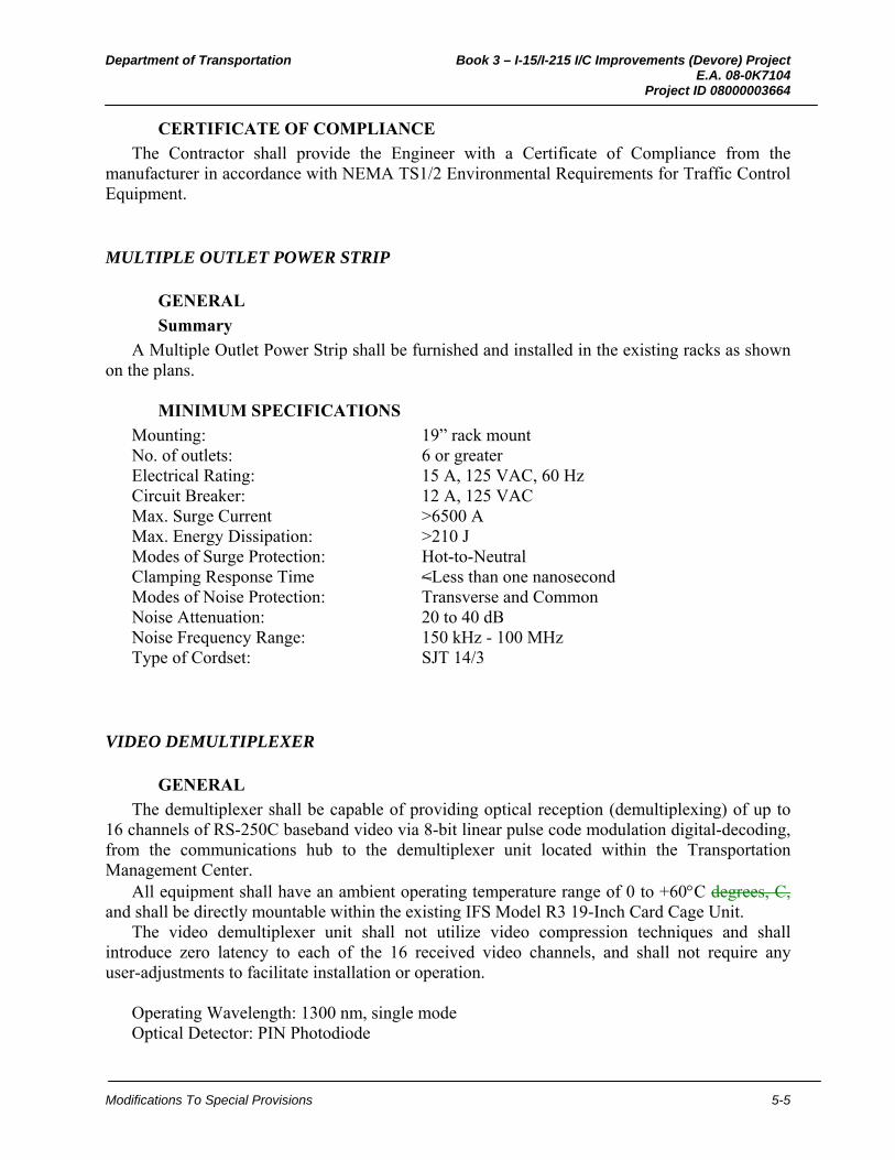
Department of Transportation Book 3 – I-15/I-215 I/C Improvements (Devore) Project E.A. 08-0K7104 Project ID 08000003664
Modifications To Special Provisions 5-5
CERTIFICATE OF COMPLIANCE
The Contractor shall provide the Engineer with a Certificate of Compliance from the manufacturer in accordance with NEMA TS1/2 Environmental Requirements for Traffic Control Equipment.
MULTIPLE OUTLET POWER STRIP
GENERAL
Summary
A Multiple Outlet Power Strip shall be furnished and installed in the existing racks as shown on the plans.
MINIMUM SPECIFICATIONS
Mounting: 19” rack mount No. of outlets: 6 or greater Electrical Rating: 15 A, 125 VAC, 60 Hz Circuit Breaker: 12 A, 125 VAC Max. Surge Current >6500 A Max. Energy Dissipation: >210 J Modes of Surge Protection: Hot-to-Neutral Clamping Response Time <Less than one nanosecond Modes of Noise Protection: Transverse and Common Noise Attenuation: 20 to 40 dB Noise Frequency Range: 150 kHz - 100 MHz Type of Cordset: SJT 14/3
VIDEO DEMULTIPLEXER
GENERAL
The demultiplexer shall be capable of providing optical reception (demultiplexing) of up to 16 channels of RS-250C baseband video via 8-bit linear pulse code modulation digital-decoding, from the communications hub to the demultiplexer unit located within the Transportation Management Center.
All equipment shall have an ambient operating temperature range of 0 to +60C degrees, C, and shall be directly mountable within the existing IFS Model R3 19-Inch Card Cage Unit.
The video demultiplexer unit shall not utilize video compression techniques and shall introduce zero latency to each of the 16 received video channels, and shall not require any user-adjustments to facilitate installation or operation.
Operating Wavelength: 1300 nm, single mode Optical Detector: PIN Photodiode

Department of Transportation Book 3 – I-15/I-215 I/C Improvements (Devore) Project E.A. 08-0K7104 Project ID 08000003664
Modifications To Special Provisions 5-6
Optical Connector Type: Type SC Operating Power: 115 V(ac) LED status indicators shall be provided on the video demultiplexer unit for ascertaining the
status of the following parameters: A. Video sync presence for each video output channel B. Optical Carrier Detect/Link-Lock C. Operating Power The 16-channel video multiplexer and demultiplexer units shall provide the following video
transmission performance end-to-end with an optical path loss of 18 dB between the two units: A. Video Signal-to-Noise Ratio: 60 dB, at a maximum optical path loss of 18 dB. B. Video Bandwidth: 5 Hz. to 6.5 MHz. C. Differential Gain: <2 percent. D. Differential Phase: <0.7 degrees. E. Tilt: <1 percent.
Installation
The video demultiplexer system shall be installed at the TMC as shown on plans and specified in these special provisions. The Contractor shall:
A. Connect the correct optical pigtail or patch cord to the optical connector on the transmitters and receivers, as well as the correct video interface cables to the demodulator inputs and demodulator outputs as specified by the equipment manufacturer.
B. Coordinate the physical space required by the Video demodulator with the space allocated with any other equipment.
C. Connect the video demodulator power supply to one of the 120 V(ac), 60 Hz power receptacles reserved for communication equipment in the TMC. The fiber optic path for each video link shall be tested and verified in accordance with the contract prior to installing the video demodulator.
D. Neatly install all drop cables together, route them along the same path and neatly secure them to the support rails in the equipment racks. No cable shall be installed with a bend radius less than the manufacture’s minimum recommended bending radius.

Department of Transportation Book 3 – I-15/I-215 I/C Improvements (Devore) Project E.A. 08-0K7104 Project ID 08000003664
Modifications To Special Provisions 5-1
6. MODIFY FIBER OPTIC COMMUNICATION SYSTEM
10-3.27 MODIFY FIBER OPTIC COMMUNICATION SYSTEM
GENERAL
SUMMARY
H Gill Concur, Fd, 2/2/11
RA ISdR***
Modify fiber optic communication system Modify This work includes furnishing and installing the following equipment and performing testing as per as shown on the plans, in conformance with the these special provisions and Section 86 "Signals, Lighting and Electrical Systems" of the Standard Specifications:
EDIT AS NECESSARY, DOES NOT CONTAIN ALL ITEMS******** Description
Fiber Optic Conduit Innerduct Fiber Optic Splice Vault Tracer Wire Fiber Optic Trench Delineators Underground Warning Tape Sealing Plugs Fiber Optic Labeling Fiber Optic Outside Plant Cable Fiber Optic Cable Splices Fiber Optic Splice Closure Fiber Optic Splice Trays Distribution Interconnect Package Fiber Optic Jumpers and Pigtails Connectors Couplers Interconnect and Termination Unit Fiber Distribution Unit Network to Serial Adapter Card Category 5E Cable Element Fiber Optic Switch LAN Extender Ethernet Switch Ethernet to Serial Converter TOS Fiber Optic Switch Fiber Optic Testing System Testing and Documentation
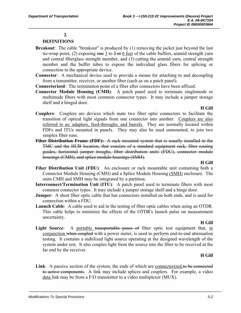
Department of Transportation Book 3 – I-15/I-215 I/C Improvements (Devore) Project E.A. 08-0K7104 Project ID 08000003664
Modifications To Special Provisions 5-2
2.
DEFINITIONS
Breakout: The cable "breakout" is produced by (1) removing the jacket just beyond the last tie-wrap point, (2) exposing one 3 to 2 m 6 feet of the cable buffers, aramid strength yarn and central fiberglass strength member, and (3) cutting the aramid yarn, central strength member and the buffer tubes to expose the individual glass fibers for splicing or connection to the appropriate device.
Connector: A mechanical device used to provide a means for attaching to and decoupling from a transmitter, receiver, or another fiber (such as on a patch panel).
Connectorized: The termination point of a fiber after connectors have been affixed. Connector Module Housing (CMH): A patch panel used to terminate singlemode or
multimode fibers with most common connector types. It may include a jumper storage shelf and a hinged door.
H Gill Couplers: Couplers are devices which mate two fiber optic connectors to facilitate the
transition of optical light signals from one connector into another. Couplers are also referred to as: adapters, feed-throughs, and barrels. They are normally located within FDFs and ITUs mounted in panels. They may also be used unmounted, to join two simplex fiber runs.
Fiber Distribution Frame (FDF): A rack mounted system that is usually installed in the TMC and the HUB location, that consists of a standard equipment rack, fiber routing guides, horizontal jumper troughs, fiber distribution units (FDU), connector module housings (CMH), and splice module housings (SMH).
H Gill Fiber Distribution Unit (FDU): An enclosure or rack mountable unit containing both a
Connector Module Housing (CMH) and a Splice Module Housing (SMH) enclosure. The units CMH and SMH may be integrated by a partition.
Interconnect/Termination Unit (ITU): A patch panel used to terminate fibers with most common connector types. It may include a jumper storage shelf and a hinge door.
Jumper: A short fiber optic cable that has connectors installed on both ends, and is used for connection within a FDU.
Launch Cable: A cable used to aid in the testing of fiber optic cables when using an OTDR. This cable helps to minimize the effects of the OTDR's launch pulse on measurement uncertainty.
H Gill Light Source: A portable transportable piece of fiber optic test equipment that, in
conjunction when coupled with a power meter, is used to perform end-to-end attenuation testing. It contains a stabilized light source operating at the designed wavelength of the system under test. It also couples light from the source into the fiber to be received at the far end by the receiver.
H Gill
Link: A passive section of the system, the ends of which are connectorized.to be connected to active components. A link may include splices and couplers. For example, a video data link may be from a F/O transmitter to a video multiplexer (MUX).

Department of Transportation Book 3 – I-15/I-215 I/C Improvements (Devore) Project E.A. 08-0K7104 Project ID 08000003664
Modifications To Special Provisions 5-3
H Gill Optical Time Domain Reflectometer (ODTR): A piece of fiber optic test equipment
similar in appearance to an oscilloscope that is used to measure the total amount of power loss between two points. It provides a visual and printed display of the relative location of system components such as fiber sections, splices and connectors as well as the losses that are attributed to each component and or defects in the fiber.
H Gill Patchcord: A short jumper used to join two Connector Module Housing (CMH) couplers,
and or a CMH and an active optical electronic device. H Gill
Pigtail: Relatively short length of fiber optic cable that is connectorized on only one end. All pigtails shall be tight buffer cable.
H Gill Power Meter: A portable transportable piece of fiber optic test equipment that, when
coupled with a light source, is used to perform end-to-end attenuation testing. It contains a detector that is sensitive to light at the designed wavelength of the system under test. Its display indicates the amount of power injected by the light source that arrives at the receiving end of the link.
Ping: For testing purposes, a "ping" is defined as: a computer network administration utility used to test whether a particular host is reachable across an internet protocol (IP) network. The IP addressable equipment shall be "pinged" a minimum of 5 consecutive instances for each test.
Riser Cable: NEC approved cable installed in a riser (a vertical shaft in a building connecting one floor to another).
Segment: A section of F/O cable that is not connected to any active device and may or may not have splices per the design.
Splice: The permanent joining of fiber ends to identical or similar fibers. Splice Closure: A container used to organize and protect splice trays. The container allows
splitting or routing of fiber cables from multiple locations. The container is environmentally sealed to protect the fibers.
Splice Module Housing (SMH): The SMH stores splice trays as well as pigtails and short cable lengths.
Splice Tray: A container used to organize and protect spliced fibers. Storage Cabinet: Designed for holding excess cable slack for protection. The storage
cabinet allows the user flexibility in equipment location and the ability to pull cable back for resplicing.
RA
3. Glossary
F/O: Fiber optic. FOC: Fiber optic cable. FOIP: Fiber optic inside plant cable. FOP: Fiber optic outside plant cable. FOTP: Fiber optic test procedure(s) as defined by EIA/TIA standards.

Department of Transportation Book 3 – I-15/I-215 I/C Improvements (Devore) Project E.A. 08-0K7104 Project ID 08000003664
Modifications To Special Provisions 5-4
4.
FIBER OPTIC CONDUIT
RA** Fiber optic conduit is defined as conduit that will contain innerduct or fiber optic cable, as
shown on the plans. Furnishing and installing fiber optic conduit shall conform to the provision of section "Conduit" of these special provisions and these special provisions the following.
5.
RA** All fiber optic conduits to be installed underground shall be either Type 1, Type 3
Schedule 80. or Type 5, except as specified herein, and that the conduit between the vaults at approximate Stations XX+XX and XX+XX shall be Type 3.
6.
Type 1 or Type 5 conduit shall be used in bridges.
7.
Type 2 conduit shall be used from the bridge to the first pull box or splice vault.
8.
H Gill Type 1 or Type 5 conduit shall be used for fiber optic conduit bends, except when using
conduit with integral innerduct. Minimum conduit bend radius shall be 10 times trade diameter of the conduit.
9.
ISdR*** Direct coupling of Type 1 or Type 5 to Type 3 fiber optic conduit will be permitted at
underground locations by means of an industry standard rigid non-metallic conduit coupling. The coupling shall be the type for joining threaded conduit to solvent welded conduit.
10.
When Type 3 Schedule 80 fiber optic conduit is placed in a trench that is not in a pavement area it shall conform to section 86-2.05C "Installation" of the Standard Specifications" except where the top 100 mm of fine soil or sand shall be 150 mm. the trench shall be backfilled with commercial quality colored concrete, as described elsewhere in these special provisions, containing not less than 250 kg of portland cement per cubic meter, to the dimensions shown on the plans. The trench shall be wide enough for a minimum of 25 mm of concrete between the wall of the trench and the side of the conduit. Other conduits in a shared trench shall be placed as shown on the plans.
11.
Concrete used to backfill trenches shall have a 24-hour curing period. The trenches shall have barricades with "Open Trench" signs posted at the beginning of the trench and every 60 meters thereafter.
12.
Conduit trenches in or adjacent to paved shoulders shall be backfilled within 3 calendar days.
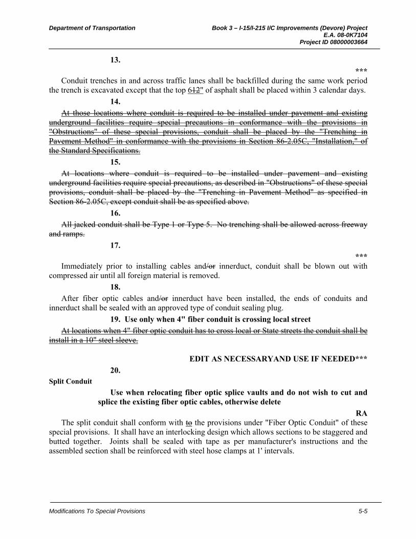
Department of Transportation Book 3 – I-15/I-215 I/C Improvements (Devore) Project E.A. 08-0K7104 Project ID 08000003664
Modifications To Special Provisions 5-5
13.
*** Conduit trenches in and across traffic lanes shall be backfilled during the same work period
the trench is excavated except that the top 612" of asphalt shall be placed within 3 calendar days.
14.
At those locations where conduit is required to be installed under pavement and existing underground facilities require special precautions in conformance with the provisions in "Obstructions" of these special provisions, conduit shall be placed by the "Trenching in Pavement Method" in conformance with the provisions in Section 86-2.05C, "Installation," of the Standard Specifications.
15.
At locations where conduit is required to be installed under pavement and existing underground facilities require special precautions, as described in "Obstructions" of these special provisions, conduit shall be placed by the "Trenching in Pavement Method" as specified in Section 86-2.05C, except conduit shall be as specified above.
16.
All jacked conduit shall be Type 1 or Type 5. No trenching shall be allowed across freeway and ramps.
17.
*** Immediately prior to installing cables and/or innerduct, conduit shall be blown out with
compressed air until all foreign material is removed.
18.
After fiber optic cables and/or innerduct have been installed, the ends of conduits and innerduct shall be sealed with an approved type of conduit sealing plug.
19. Use only when 4" fiber conduit is crossing local street
At locations when 4" fiber optic conduit has to cross local or State streets the conduit shall be install in a 10" steel sleeve.
EDIT AS NECESSARYAND USE IF NEEDED***
20. Split Conduit
Use when relocating fiber optic splice vaults and do not wish to cut and splice the existing fiber optic cables, otherwise delete
RA The split conduit shall conform with to the provisions under "Fiber Optic Conduit" of these
special provisions. It shall have an interlocking design which allows sections to be staggered and butted together. Joints shall be sealed with tape as per manufacturer's instructions and the assembled section shall be reinforced with steel hose clamps at 1' intervals.

Department of Transportation Book 3 – I-15/I-215 I/C Improvements (Devore) Project E.A. 08-0K7104 Project ID 08000003664
Modifications To Special Provisions 5-6
21.
INNERDUCT
*** RA**
Innerduct shall be installed wherever fiber optic cable is installed in conduit, except conduit housing Type D fiber optic cable. Wherever 4 inch conduit is required, four Size 3/4 inch innerducts shall be installed unless otherwise specified.
22.
Copper cable shall not be mixed with F/O cable within the same innerduct.
23.
Innerduct consists of an extruded flexible annealed polyethylene tubing that is installed inside conduit, and which in turn the fiber optic cable is installed. Innerduct within a conduit run shall be continuous without splices or joints. Innerduct for this project shall be continuous longitudinally ribbed inside and outside.
24.
*** Unless otherwise shown on the plans, innerduct for this project shall be nominal 13/4 inch
inside diameter, with wall thickness of 2300 µm ±8076 µm, (0.0906 inch ± 0.003 inch), and shall meet the following requirements:
HSGill
24a.
1. Polyethylene for innerduct shall have a density of 0.955 ±0.005 gm/cm3 (ASTM Standard D-1505), and shall conform to the applicable portions of ASTM Designations: D 3485, D 3035, D 2239, and D 2447, and the applicable portions of NEMA TC7 and TC2. Tensile yield strength shall be a minimum of 23 Mpa22 753 kPa, (ASTM D-638).
RA 1. Polyethylene for innerduct shall have a density of 59.6187 ±0.3121 lb/in3 (ASTM
Designation: D 1505) and shall conform to the applicable requirements of ASTM Designation: D 3485, D 3035, D 2239, and D 2447, and the applicable requirements of NEMA TC7 and TC2. Tensile yield strength shall be 3300 psi minimum in accordance with the requirements in ASTM Designation: D 638 retain English units
24b.
H Gill ***
2. Different innerducts within the same conduits shall be different colors and the colors chosen shall be consistent with the required cables throughout the project. See the table below:
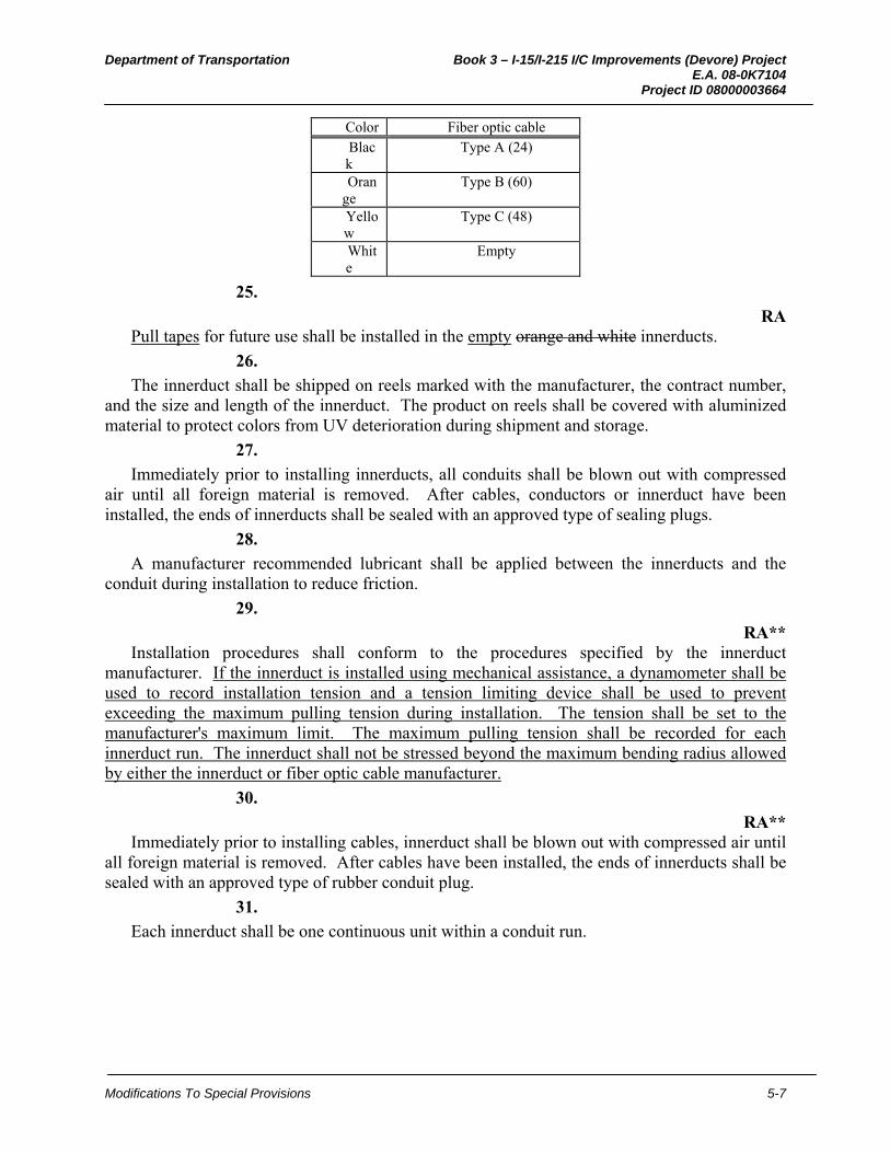
Department of Transportation Book 3 – I-15/I-215 I/C Improvements (Devore) Project E.A. 08-0K7104 Project ID 08000003664
Modifications To Special Provisions 5-7
Color Fiber optic cable Black
Type A (24)
Orange
Type B (60)
Yellow
Type C (48)
White
Empty
25.
RA Pull tapes for future use shall be installed in the empty orange and white innerducts.
26.
The innerduct shall be shipped on reels marked with the manufacturer, the contract number, and the size and length of the innerduct. The product on reels shall be covered with aluminized material to protect colors from UV deterioration during shipment and storage.
27.
Immediately prior to installing innerducts, all conduits shall be blown out with compressed air until all foreign material is removed. After cables, conductors or innerduct have been installed, the ends of innerducts shall be sealed with an approved type of sealing plugs.
28.
A manufacturer recommended lubricant shall be applied between the innerducts and the conduit during installation to reduce friction.
29.
RA** Installation procedures shall conform to the procedures specified by the innerduct
manufacturer. If the innerduct is installed using mechanical assistance, a dynamometer shall be used to record installation tension and a tension limiting device shall be used to prevent exceeding the maximum pulling tension during installation. The tension shall be set to the manufacturer's maximum limit. The maximum pulling tension shall be recorded for each innerduct run. The innerduct shall not be stressed beyond the maximum bending radius allowed by either the innerduct or fiber optic cable manufacturer.
30.
RA** Immediately prior to installing cables, innerduct shall be blown out with compressed air until
all foreign material is removed. After cables have been installed, the ends of innerducts shall be sealed with an approved type of rubber conduit plug.
31.
Each innerduct shall be one continuous unit within a conduit run.

Department of Transportation Book 3 – I-15/I-215 I/C Improvements (Devore) Project E.A. 08-0K7104 Project ID 08000003664
Modifications To Special Provisions 5-8
EDIT AS NECESSARYAND USE IF NEEDED***
32. Split Wall Innerduct
Use when relocating fiber optic splice vaults and do not wish to cut and splice the existing fiber optic cables, otherwise delete
RA ISdR***
The split wall innerduct shall conform to the provisions under "Innerduct" of these special provisions.Innerduct shall be installed wherever F/O cable is installed in conduit. Four Split wall innerducts (hereafter written as "innerduct") shall be installed in the 4 inch fiber optic conduit as shown on the plans. The fourth innerduct shall be the non-slit wall type. Each fiber optic cable shall be installed in its own innerduct. Copper cable shall not be mixed with F/O cable within the same innerduct.
33.
FIBER OPTIC SPLICE VAULT
Fiber optic splice vaults shall conform to the Western Underground Committee Guide No. 3.6 "Nonconcrete Enclosures," except where differences are noted here, and the details on the plans. Fiber optic splice vaults shall have minimum inside clearance of 914 mm 3 feet (W) x 1520 mm 5 feet (L) x 1520 mm 5 feet (D).
34.
Covers shall be 2 piece torsion assisted sections. Cover marking shall be "CALTRANS FIBER OPTICS" on each cover section.
35.
Each cover section shall have inset lifting pull slots.
36.
Cover hold down bolts or cap screws and nuts shall be of brass, stainless steel, or other non-corroding metal material.
37.
Covers shall be hot dipped galvanized steel.
38.
Fiber optic splice vaults and covers shall be rated for AASHTO HS 20-44 loads and installed as detailed and where shown on the plans.
39.
A concrete encasement ring shall be poured around the splice vault as shown on the plans.
Concrete placed around and under traffic splice vaults as shown on the plans shall contain a minimum of 325 kg 20.3 lbs of portland cement per cubic foot.

Department of Transportation Book 3 – I-15/I-215 I/C Improvements (Devore) Project E.A. 08-0K7104 Project ID 08000003664
Modifications To Special Provisions 5-9
40.
Hangers shall be made of a non-corroding material and be free of any sharp edges. A separate hanger shall be provided for each type of fiber optic cable and be securely fastened to the side wall with the slack fiber optic cable neatly coiled in a figure-eight configuration.
41.
A minimum of two "U shaped" knockouts are required on each side of the vault and shall be configured to allow for future removal of the vault without disturbing the existing conduits.
42. Use on all District 8 projects instead of a rectangular splice vault, where a splice vault is needed in a paved AC shoulder only.
Fiber Optic Splice Vault-Round
Fiber optic splice vaults shall conform to the Western Underground Committee Guide No. 3.6, "Nonconcrete Enclosures," except where differences are noted here or detailed on the plans. Dimensions of round traffic fiber optic splice vaults shall be as shown on the plans.
43.
Fiber optic splice vault covers shall be rated for AASHTO HS 20-44 loading and shall be installed at the locations and in the manner shown on the plans. Concrete place around and under traffic splice vaults shall be minor concrete and shall contain not less than 325 kg 20.3 lbs of portland cement per cubic meter foot.
44.
Hangers shall be made of a non-corroding material and be free of any sharp edges. A separate hanger shall be provided for each type of fiber optic cable and be securely fastened to the side wall of the vault allowing the slack fiber optic cable to be neatly coiled in a circular configuration.
45.
Pulling eyes shall be installed as necessary to accommodate pulling of cables.
46.
RA** Tops of fiber optic vaults shall be installed at grade in paved areas and 25 mm1" above grade
in unpaved areas. RA**
47.
The round fiber optic vaults shall be installed at grade level in paved areas. and shall be set at 1" above grade in unpaved areas.
Department of Transportation Book 3 – I-15/I-215 I/C Improvements (Devore) Project E.A. 08-0K7104 Project ID 08000003664
Modifications To Special Provisions 5-10
48. To be used on all District 8 fiber optic projects with 4" conduits with fiber
TRACER WIRE
RA Tracer wire shall be provided and placed in the trench over PVC conduits containing fiber
optic cable and as shown in the plans. The wire shall be placed 2 inches above the uppermost conduit in the trench or secured to the top of the uppermost conduit in the trench.
49.
Tracer wire shall be provided and placed in 4" conduits containing fiber optic cable and as shown on the plans.
50.
RA** Tracer wire shall be a No. 12, minimum, solid copper conductor with Type TW, THW,
RHW, or USE insulation. The tracer wire shall form a mechanically and electrically continuous line throughout the length of the trench. A minimum of 3' of slack shall be extended into each fiber optic pull box and splice vault from each direction.
51.
Tracer wires may be spliced at intervals of not less than 500'. Splices shall conform to Section 86-2.09, "Wiring," of the Standard Specifications.
52.

Department of Transportation Book 3 – I-15/I-215 I/C Improvements (Devore) Project E.A. 08-0K7104 Project ID 08000003664
Modifications To Special Provisions 5-1
7. CLOSED CIRCUIT TELEVISION SYSTEMS
10-3.28 MODIFY CLOSED CIRCUIT TELEVISION SYSTEMS
GENERAL
SUMMARY
XX
Modify Closed circuit television (CCTV) systems This work includes furnishing and installing the following equipment cabinet, camera assembly, CCTV pole and performing acceptance testing as per the plans, these special provisions and Section 86 "Signals, Lighting and Electrical Systems," of the Standard Specifications:
Description
Camera Pole System Cabinet Assembly Camera Assembly Camera Transceiver Composite Cable Acceptance Testing
2.
XX The closed circuit television (CCTV) system shall conform to all rules and regulations of the
Federal Communications Commission.
3.
XX The CCTV system shall be installed as a complete and operational system.
4.
The Contractor shall be responsible for providing any mounting adapter and bracket required for installation of the CCTV system. All materials furnished, assembled, fabricated or installed under this item shall be new, corrosion resistant and in strict accordance with the details shown on the plans and in the specifications.
5.
CAMERA POLE SYSTEM
The camera pole sheet steel shall have a minimum yield of 48,000 psi331 MPa. Modifications for hand hole, connector bracket and strain relief shall be made as shown on the plans.
Department of Transportation Book 3 – I-15/I-215 I/C Improvements (Devore) Project E.A. 08-0K7104 Project ID 08000003664
Modifications To Special Provisions 5-2
6.
The camera pole system shall include all necessary mounting hardware and wiring, foundation and anchor bolts and other equipment, as shown on the plans and specified in these special provisions.
7.
CABINET ASSEMBLY
Each cabinet assembly shall consist of the following: 1. Cabinet Enclosure 2. Power Distribution Assembly 3. Interconnect and Termination Unit
XX
8. Cabinet Enclosure
XX Each cabinet enclosure shall be constructed as per Section 86-3.04A, "Cabinet Construction,"
of the Standard Specifications for aluminum material and a NEMA 4 type with dimensions as shown on the plan sheets. This enclosure shall house the CCTV equipment, housing and mounting cage as shown on the plans.
9.
The enclosure and doors shall be fabricated of 0.125-inch minimum thickness aluminum. All exterior seams for enclosures and doors shall be continuously welded.
10.
Exterior welds shall be ground smooth. Edges shall be filed to a radius of 0.03-inch, minimum.
11.
Enclosures fabricated from aluminum sheet shall conform to the requirements in ASTM Designation: B 209 or B 209M for 5052-H32 aluminum sheet.
A. Welding on aluminum enclosures shall be done by the gas metal arc welding (GMAW)
process using bare aluminum welding electrodes. Electrodes shall conform to the requirements in American Welding Society (AWS) A5.10 for ER5356 aluminum alloy bare welding electrodes.
B. Procedures, welders and welding operators for welding on aluminum shall be qualified in conformance with the requirements in AWS B3.0, "Welding Procedure and Performance Qualification," and to the practices recommended in AWS C5.6.
C. The surfaces of each aluminum enclosure shall be finished to conform to the requirements in Military Specification MIL-A-8625C "Anodic Coatings for Aluminum and Aluminum Alloys" for a Type II, Class I coating, except that the anodic coating shall
Department of Transportation Book 3 – I-15/I-215 I/C Improvements (Devore) Project E.A. 08-0K7104 Project ID 08000003664
Modifications To Special Provisions 5-3
have a minimum thickness of 0.0007-inch and a minimum coating weight of 0.001-ounce per square inch. The anodic coating shall be sealed in a 5 percent aqueous solution of nickel acetate (pH 5.0 to 6.5) for 15 minutes at 97°C. Prior to applying the anodic coating, the enclosures shall be cleaned and etched as follows: 1. Clean by immersion in inhibited alkaline cleaner such as Oakite 61A or Diversey 909,
or equivalent, 6 ounces to 8 ounces per gallon, 71°C for 5 minutes. 2. Rinse in cold water. 3. Etch in a solution of 11/2 ounce of sodium fluoride, plus 4 ounces to 6 ounces of
sodium hydroxide per gallon of distilled water at 60°C to 65°C for 5 minutes. 4. Rinse in cold water. 5. Desmut in a 50 percent by volume nitric acid solution at room temperature for
2 minutes. 6. Rinse in cold water.
12.
The enclosure front door shall be equipped with a lock. When the door is closed and latched, the door shall be locked. The handle shall have provision for padlocking in the closed position. The handle shall have a minimum length of 7 inches and shall be provided with a 5/8 inch, minimum, steel shank. The handle shall be fabricated of cast aluminum or of zinc-plated or cadmium-plated steel. The enclosure door frame shall be designed so that the latching mechanism will hold tension on and form a firm seal between door gasketing and door frame. Enclosure locks shall be the solid brass, 6-pin tumbler rim type. The lock shall have rectangular, spring-loaded bolts. The locks shall be left hand, and rigidly mounted with stainless steel machine screws approximately 2 inches apart. Keys shall be removable in the locked and unlocked positions, and 2 keys furnished with each enclosure. The front position of the lock shall extend 1/8 inch to 3/8 inch beyond the outside surface of the door.
13.
The latching mechanism shall be a 3-point enclosure latch with nylon rollers. The center catch and pushrods shall be zinc-plated or cadmium-plated steel. Pushrods shall be turned edgewise at the outer supports and shall be 1/4" x 3/4", minimum. The nylon rollers shall have a minimum diameter of 3/4 inch and shall be equipped with ball bearings.
14.
Hinges on enclosures may be aluminum with a stainless steel hinge pin. The hinges shall be bolted to the enclosure. The hinge pins and bolts shall not be accessible when the door is closed.
15.
Gasketing shall be provided on all door openings and shall be dust-tight. Gaskets shall be permanently bonded to the metal. The mating surface of the gasketing shall be covered with a silicone lubricant to prevent sticking to the mating surface.
16.
Details of alternative designs shall be submitted for review and approval prior to the fabrication of the enclosures.

Department of Transportation Book 3 – I-15/I-215 I/C Improvements (Devore) Project E.A. 08-0K7104 Project ID 08000003664
Modifications To Special Provisions 5-4
17.
Substantial metal shelves or brackets shall be provided to support the batteries specified elsewhere.
18.
Machine screws and bolts shall not protrude beyond the outside wall of the enclosure.
19.
Conduit shall enter the enclosure at the rear unless shown otherwise on the plans.
20.
The police panel is not required.
21.
The cabinet enclosure shall include the housing and mounting cage as shown on the plans.
22. Power Distribution Assembly
The power distribution assembly shall consist of the following: 1. One 15 A, 120 V, single pole main breaker 2. Four standard 120 V receptacles 3. One duplex, 3 prong, NEMA Type 5-15R grounded utility type outlet 4. One multiple outlet strip with the following specifications: 5. Protection Modes: All 3: H-N, H-G, N-G. 6. High Frequency Noise Suppression: Up to 80 dB from 50 kHz to 1,000 MHz. 7. High Voltage Transient Spike Suppression: Up to 36,000 A spikes. 8. Cord: 6 foot with grounded 3-prong plug. 9. Diagnostic circuitry and lamps indicating:
9.1. LINE OK 9.2. LINE FAULT 9.3. PROTECTION PRESENT
23.
The power distribution assembly shall meet the following requirements: 1. Maximum Energy Absorption: 720 J 2. Transient Response Time: instantaneous (0.1 ns) 3. Rated Current and Load Handling: 15 Amperes Max (1,800 W), 15 A per socket
(1,800 Watts) Rated Voltage: 120 V(ac), 50/60 Hz. 4. Meet UL 1449, UL 1283 and UL 497A specifications.
15 A CB is listed above. JRG*** H. Circuit Breaker: 15 A.
Receptacle listed above. JRG*** I. Receptacles: 6 (NEMA 5-15R).
Department of Transportation Book 3 – I-15/I-215 I/C Improvements (Devore) Project E.A. 08-0K7104 Project ID 08000003664
Modifications To Special Provisions 5-5
24. Interconnect and Termination Unit
The Contractor shall furnish and install all related equipment to interface the rack mount interconnect and termination unit (ITU) to the incoming fiber optic communications cable and the patchcord fiber optic cable.
25.
The ITU shall be a modular enclosure that provides interconnect capability of one multi-fiber cable to a minimum of 12 single fiber cable. The ITU shall be environmentally sealed and contain grommets at the cable entrances to prevent any ingress of dirt or moisture. Strain relief shall be provided for the fiber optic cable. The ITU shall contain a splice tray, connector panel and the appropriate number of pigtails which will be fusion spliced to the incoming fiber cable. Each fiber shall be fusion spliced to a pigtail with a factory installed and polished SC connector. Each pigtail shall be labeled and secured onto cable as described elsewhere in these special provisions. Brackets shall be provided to spool the incoming fiber optic cable to minimum of 3 turns before separating out individual fibers to the connector panel.
26.
RA The ITU shall be packaged in a rack unit with approximate dimensions of 17" (W) x 2" (H) x
12" (D) and have a metal housing slide-out shelf. The ITU shall contain grommets at cable entrances and provide strain relief for the fiber cable. The ITU shall accommodate 12 singlemode fibers having SC type connector feed through adapters and 12 interconnection points or 12 splices. The components of the passive interconnect package shall be installed in the ITU.
27.
RA The ITU shall be a metal enclosure with a hinged door. The door shall have a latch or
thumbscrew to hold the door in the closed position. An opening shall be provided on the back side of the incoming fiber optic communications cable. Connector panels (for up to 12 SC connectors) shall be provided inside the enclosure. Strain relief shall be provided for the incoming fiber optic cable. A guard shall be provided to protect the patchcord fiber optic cables plugged into this enclosure.
28.
CAMERA ASSEMBLY
The camera assembly shall consist of:
Description Camera Module Environmental Enclosure Video Encoder
29.
The camera assembly units shall be fully assembled, pressurized and tested at the original manufacturing facility and shipped as a complete unit, ready for installation.

Department of Transportation Book 3 – I-15/I-215 I/C Improvements (Devore) Project E.A. 08-0K7104 Project ID 08000003664
Modifications To Special Provisions 5-6
RA
30. Camera Module
1. Image Sensor: Progressive ScanEx-View ICX445AKA CCD 2. Image Size: Diagonal (1/3" type) 3. Image Resolution: 1280 (H); 720 (V) 4. Picture Elements (total): 1348 (H) x 976 (V) 5. Video Output: 16 Bit Digital YUV: 4.2.0 6. Day/Night Operation: Adjustable (Auto, Color and Mono Modes) via removable IR cut
filter 7. Maximum Lens Aperture: f/1.6 (wide) to f/2.8 (telescopic) 8. Optical Zoom Range: 18X, 4.7 mm to 84.6 mm with X4 Digital zoom from web browser 9. Optical Zoom Speed: Two speeds, from approximately 3.5 to 5 seconds full range 10. Horizontal Angle of View: Optical: From 55.2 to 3.2 degrees 11. Minimum Focus Distance: 0.01 m (wide); 1.0 m (telescopic) 12. Auto Focus: Selectable Auto/Manual; Minimum Scene Illumination for Reliable Auto
Focus shall be no more than 50 percent video output. 13. Manual Shutter: Selectable shutter speeds shall be from 1/30 to 1/10,000. 14. Auto Iris; Selectable auto/manual; Iris shall automatically adjust to compensate for
changes in scene illumination to maintain constant video level output within sensitivity specifications.
15. Sensitivity: Scene Illumination; F1.6 at 50 percent video 16. 1.8 Lux (0.18 fc) at 1/30 shutter, color mode 17. 0.1 Lux (0.01 fc) at 1/30 shutter, mono mode
31. Environmental Enclosure
The environmental enclosure shall be a corrosion resistant and tamperproof sealed and pressurized housing with 5 psi dry nitrogen with Schrader purge fitting and 20 psi relief valve for each camera. The size of the housing shall be 3.5 in diameter or smaller.
32.
The camera housing shall include a loss of pressure sensor that will trigger an alarm message that will be inserted in the video output signal when the pressure drops below 0.5 psi.
33.
The enclosure shall be constructed from 6061-T6 standard aluminum tubing with a wall thickness of 0.25 ±0.03 inch. Internal components shall be mounted to a rail assembly. A copper plated spring-steel ring shall be used to ensure electrical bonding of the rail assembly and components to the camera housing. The housing exterior shall be finished by pre-treatment with conversion coating and baked enamel paint. The camera enclosure shall be designed to withstand the effects of sand, dust, and hose-directed water.

Department of Transportation Book 3 – I-15/I-215 I/C Improvements (Devore) Project E.A. 08-0K7104 Project ID 08000003664
Modifications To Special Provisions 5-7
34.
The internal humidity of the housing shall be less than 10 percent, when sealed and pressurized. Desiccant packs shall be securely placed inside the housing to absorb any residual moisture and maintain internal humidity at 10 percent or less.
35.
A sun shield shall be provided to shield the entire housing from direct sunlight.
36.
The camera assembly shall meet the following requirements:
RA
36a.
1. Pan and Tilt Drive Unit Requirements:
1.1. Must be capable of continuous rotation in either direction. 1.2. Tilt movement shall be 130 degrees, from +40 to – 90 degrees unobstructed. 1.3. Pan Speed (Operator Control) shall be variable from 0.1°/s to 40 °/s 1.4. Pan Speed (Preset Control) shall be greater than 100°/s 1.5. Tilt Speed (Operator Control): Variable from 0.1°/s to 20°/s 1.6. Tilt Speed (Preset Control): 40°/s 1.7. The 64 Pan and Tilt preset positions shall be repeatable within ± 0.5°
36b.
2. Power Requirements:
2.1. Operating voltage shall be from 108 V(ac) to 132 V(ac), 120 V(ac) nominal, 50/60 Hz. (±3.0 Hz).
2.2. Power consumption shall not exceed a total of 95 Watts. 2.3. Camera/receiver/P&T driver (pan & tilt in motion) power not to exceed 40 Watts. 2.4. Power for the heater (heater on) shall not exceed 6 Watts.
36c.
3. Environmental Specifications The environmental enclosure shall meet the minimum standard requirements as set forth in
Section 2 of the NEMA Standard Publication No. TS2 for temperature, vibration, shock, external icing, corrosion protection and the following:
1. Temperature: -34C to 74C tested across low and high voltage ranges per Nema-TS2
paragraphs 2.1.2 and 2.1.3. 2. Vibration: Per Nema-TS2 paragraphs 2.1.9, 2.2.3, 5-30Hz sweep @ 0.5g applied in each
of 3 mutually perpendicular planes. 3. Shock: Per Nema-TS2 paragraphs 2.1.10, 2.2.4, 10g applied in each of 3 mutually
perpendicular planes.
Department of Transportation Book 3 – I-15/I-215 I/C Improvements (Devore) Project E.A. 08-0K7104 Project ID 08000003664
Modifications To Special Provisions 5-8
3.1. Water Spray: Per IEC 60529+A1, 1999, Para 14.2.6, Solid water stream delivered thru 12.5 mm nozzle at 25 gallons/minute at 9 ft for 3 minutes
5. External Icing: Per Nema-TS2 250-2003, paragraphs 5.6 6. Corrosion Protection: Per Nema 250-2003, paragraphs 5.10
3.2. Humidity: From 0 to 100 percent N.C per MIL-E-5400T, paragraphs 3.2.24.4 3.3. Standards: IP66, IP67, ASTM-B117 Marine
36d.
4. Mechanical Specifications:
4.1. The weight shall not exceed 28 lb. 4.2. The dimensions shall not exceed 17" (height) by 11" (width).
ISdR***
RA
36e.
5. Mounting Specifications Four (4) mounting holes shall be from 0.39 inches to 0.43 inches in diameter and match the
bolt pattern as detailed in Caltrans standard the plans sheet ES-16A (Camera Mounting Plate) as found in the Standard Plans.
36f.
6. Main Interface Connector The main interface connector shall be equivalent to an Amphenol 206036-3 with back shell
206070-1 and mating connector equivalent to an Amphenol 206037-11 with clamp 206070-1.
37. Video Encoder
The CCTV assembly system shall fully integrate within the H.264/MJPEG encoding component with functions as specified below:
1. Video Encoding: H.264 (Main Profile/Level 3.1) and MJPEG standards. 2. Video Streams: Two independently configurable streams; (2) H.264 streams or (1)H.264
and (1) MJPEG or (1) H.264 or MJPEG and 1 NTSC. ISdR***
3. Video Stream Configuration Properties (Stream Settings): 3.1. Video Stream 1: H.264 3.2. Video Stream 2: H.264 or MJPEG
64. Image Resolution: 720p, D1, VGA, CIF 75. Streaming Mode: CBR or VBR 86. Image Settings: (GOP (M, N)), Quality Value 97. Frame Rate: 30, 15, 7, 4, 2, 1
Department of Transportation Book 3 – I-15/I-215 I/C Improvements (Devore) Project E.A. 08-0K7104 Project ID 08000003664
Modifications To Special Provisions 5-9
108. Connection Types: Uni-cast, multi-unicast or multi-cast 119. Data Rate: Adjustable from 64 k to 8 Mb/s CCTV assembly Video Latency:
<150 ms 1210. Network Protocol Layers: RTP, RTSP, UDP, TCP, IP, HTTP, IGMPv2, ICMP,
ARP as a minimum
38.
Operational parameters of the video encoder shall meet the following:
38a.
1. Functional Capabilities:
1.1. Provide an integrated network Internet Protocol (IP) camera providing: 720p/30 video with H.264/MJPEG compression and encoding for providing video images transported over standard Ethernet infrastructures.
1.2. Integrate an HDTV standards 720p resolution at 30 frames/s day/night camera with integral 18x motorized zoom optics, an H.264/MJPEG ASIC based encoding engine and network communication circuitry Automatic and user-selectable speed setting
1.3. Support for uni-cast and multi-cast connections, using RTP/RTSP network layers 1.4. Provide an integral web HTTP server allowing password protected
administration/configuration capabilities along with full camera and positioning system control and viewing functions.
1.5. Provide a software development kit (SDK) for allowing any 3rd party developers all necessary tools for integrating the camera assembly system into the users control system environment.
1.6. Provide hybrid capability delivering both Ethernet and analog composite video and RSEIA-422 serial connections for external system connections and control.
1.7. The positioning drive system shall provide speed capability from 0.1 to 80 degrees per second, with a 0.25 degree repeatability, 360 degree continuous pan rotation, and from +90 to –90 degree tilt range as a minimum.
1.8. Include an advanced ID generation capability for indications of viewing direction, compass setting, azimuth/elevation position, location descriptors and user defined image/logo.
1.9. Be designed conforming to NEMA TS2 requirements for power, shock and vibration as well as IP66 and IP67 environmental standards.
38b.
2. Communication and Camera Addressing Protocol:
2.1. Serial data communications ports conforming to EIA/TIA-232 and EIA/TIA-422. 2.2. Configurable to support NTCIP 1205 v01.08 - NTCIP Objects for CCTV Camera
Control. 2.3. Via the CCTV protocol, the user shall be able to obtain camera position information
including tilt angles, pan positions and zoom levels. The information shall be
Department of Transportation Book 3 – I-15/I-215 I/C Improvements (Devore) Project E.A. 08-0K7104 Project ID 08000003664
Modifications To Special Provisions 5-10
supplied as from zero degree to 359 degrees azimuth and from –95 degree to +95 degree elevation.
2.4. Cohu and Javelin protocols or equivalent. 2.5. TCP/IP 100 Base T Fast Ethernet data communication port.
38c.
Upon receipt of any given command, the camera positioning system shall not take longer than 1.0 second to respond.
38d.
All programmable functions shall be stored in non-volatile memory and shall not be lost if a power failure occurs. System configurations such as video privacy zones, preset text and sector ID shall be able to be stored in a computer file and a camera personality can be cloned or uploaded into a camera in the event that a camera replacement is necessary.
38e.
The communications transmission interface shall be terminated with appropriate connector. If required a converter shall be supplied to transform EIA-422 to EIA-232.
38f.
3. Backward Compatibility with Mpc-M-100/104/105 Master Controller:
3.1. Address Selection: Same on Camera Positioning System. 3.2. Camera Power ON/OFF: Camera turns on/off. 3.3. Auto / Manual Iris Select: Same on Camera Positioning System. 3.4. Fast / Slow: Provides two speeds for zoom. 3.5. Auto / Manual Color Balance Select: Auto / Manual shutter Select on Camera
Positioning System. 3.6. BLUE: Increases blue level. 3.7. RED: Increases red level. 3.8. ZOOM: Same on Camera Positioning System. 3.9. FOCUS: Focus Control if in Manual focus mode, no effect if in auto focus mode. 3.10. IRIS: Iris Control if in Manual iris, no effect if in auto iris. 3.11. PAN / TILT: Controls Pan and Tilt direction. Speed of pan and tilt is determined
by Fast / Slow mode selection and by optical zoom position of lens, so that the narrower the field of view the slower the pan and tilt speed. In the fast mode, the pan speed shall be adjusted to provide approximately 1 1/2 to 2 1/2 fields of view per second. In the slow mode the pan speed shall be adjusted to provide approximately 1/2 to 1 field of view per second. The tilt speed shall be adjusted to remain proportional to the pan speed.
38g.
4. Presets Allows Presets 1 through 10 to be set or recalled. Selecting presets 1-10 shall control presets
33 through 42 stored in Camera Positioning System.

Department of Transportation Book 3 – I-15/I-215 I/C Improvements (Devore) Project E.A. 08-0K7104 Project ID 08000003664
Modifications To Special Provisions 5-11
38h.
5. Character Generator Specifications:
5.1. ID Characters are white with a black border. 5.2. A maximum of six lines of user programmable alphanumeric text can be displayed,
plus two fixed display lines for low-pressure indicator and Privacy Zones. 5.3. Text shall only be displayed in uppercase characters. 5.4. Camera ID shall be up to 2 lines, each up to 24 characters long. If both lines are
programmed Line 1 of Camera ID shall always appear above Line 2 of Camera ID regardless of top or bottom selection.
5.5. Preset ID: 1 line with up to 24 characters long, user programmable for each of the 64 preset positions. When a preset position is recalled the corresponding preset ID shall be displayed. The preset ID shall remain displayed until a pan, tilt, zoom, manual focus, auto focus select, or another preset command is received.
5.6. Low Pressure Indicator: 1 line, "Low Pressure", messages shall be displayed in "blinking" or "non-blinking" mode and be displayed when activated by low internal pressure. Adjustable set points by altitude shall be provided via the serial port to activate low-pressure. Message shall be enabled or disabled.
5.7. Temperature Indicator shall be 1 line, in degrees C and numeric messages shall be displayed in "blinking" or "non-blinking" mode. Message shall be enabled or disabled.
5.8. Sector Message: Up to 16 sectors in 360 degrees may be defined with up to 24 characters long.
5.9. Message shall be programmable via the RS-422 serial communications. 5.10. Message positioning shall be accomplished by padding left side of message with
spaces. 5.11. Messages can be positioned at either the top or the bottom of display. Blank lines
are not displayed. Any programmed line being displayed shall fill in toward the top if top positioning is selected or toward the bottom if bottom position is selected.
38i.
6. Privacy Zones: Video blanking for up to 8 Privacy zones shall be provided. The video shall be blanked out
for privacy of 1 line; numeric messages can also be displayed. Message shall be displayed in "blinking" or "non-blinking" mode and be enabled or disabled. Privacy Zones shall be programmed via the RS-422 serial communications.
38j.
7. Maintenance Functions:
JRG*** The camera system shall support maintenance features as defined below: 7.1. Querying of camera parameters via the Ethernet connection. 7.2. The camera parameters consists of:
Department of Transportation Book 3 – I-15/I-215 I/C Improvements (Devore) Project E.A. 08-0K7104 Project ID 08000003664
Modifications To Special Provisions 5-12
7.2.1. Serial Number 7.2.2. Software Revision 7.2.3. Assembly Date 7.2.4. Camera Model Number 7.3. Internal temperature and pressure monitoring and reporting 7.4. Remote software upload and updates via Ethernet 7.5. Camera device auto discovery of IP address 7.6. Camera system auto re-connect 7.7. Camera system reset 7.8. Save and restore camera system start-up configuration
38k.
8. IP Management:
JRG*** The CCTV assembly shall provide at minimum the following network configuration
properties: 8.1. IP Configuration: DHCP or Static IP address entry. 8.2. Net mask address entry 8.3. Gateway address entry 8.4. Domain name entry 8.5. DNS server entry
38l.
9. Tour Sequencing Requirements:
9.1. Eight - tour sequence may be defined. 9.2. Programming of the tour sequences shall be accomplished by the selection of a
preset position (by number), and then selection a dwell time. The presets can be used in any order, and the same preset may be used more than once as long as the total number of preset positions used does not exceed 32.
9.3. The dwell time defines the length of time paused at each preset position. It can be from 1 second to 60 seconds. The dwell time is can be changed individually for all stops on the tour.
9.4. If the appropriate preset ID is programmed, it shall be displayed for each preset position used on the tour.
9.5. The tour shall stop upon receipt of a pan command. 9.6. All programmable functions shall be stored in non-volatile memory.
RA

Department of Transportation Book 3 – I-15/I-215 I/C Improvements (Devore) Project E.A. 08-0K7104 Project ID 08000003664
Modifications To Special Provisions 5-13
39.
CAMERA TRANSCEIVER
The Contractor shall furnish and install a camera transceiver (TCVR) at the camera site to interface with the CCTV camera assembly, and with the fiber optic cable.
40.
The TCVR shall operate on one single mode fiber.
41.
The TCVR shall support high quality, simultaneous two-way transmission of camera control data and one-way transmission of camera video over one single mode fiber. The TCVR shall receive RS-232 data for the CCTV assembly and shall transmit NTSC video from the CCTV camera assembly.
42.
The TCVR video transmission and data receiving format used in the camera junction box shall be compatible with the TCVR video receiving and data transmitting format used in the communications hub structure.
43.
The TCVR may be packaged as one surface mountable module or may be individual components such as a receiver, transmitter and wavelength division multiplexer to combine both data and video onto one single mode fiber.
44.
Supply voltage shall be 120 V(ac) ±10 percent, 60 Hz. Lower voltage units will be acceptable if a UL listed power conversion module is used to adapt from the 120 V(ac) source.
45.
Power required shall be 50 W maximum.
46.
Mounting shall be to a flat wall surface.
47.
*** Operating temperature range shall be from -40 to +16258 °F minimum range.
48.
Video transmitter section shall meet the following requirements:
Input Level: 1 V(p-p) (NTSC composite) Signal-to-Noise ratio at minimum receiver
input: 50 dB Min
Differential phase (From 10 to 90 percent APL):
3 degrees Max
Differential gain (From 10 to 90 percent APL):
3 percent Max
Frequency Response: From 100 kHz to 5.5 MHz: ±0.30 dB Max
From 5.5 MHz to 8 MHz: ±0.6 dB Max

Department of Transportation Book 3 – I-15/I-215 I/C Improvements (Devore) Project E.A. 08-0K7104 Project ID 08000003664
Modifications To Special Provisions 5-14
48a.
1. RS-232 receiver section shall meet the following requirements:
1.1. Data rate: From DC to 9.6 kbps Min
1.2. Bit error rate: 10-9 Max
48b.
2. Optical shall meet the following requirements:
1. Video transmitter shall meet the following requirements: 2.1. Operating wavelength: 1300 nm or 1550 nm 2.2. Launch power: -14 dBm Min 2.3. Sensitivity (receiver): -28 dBm Max 2.4. Loss budget: 14 dB Min 2.5. Fiber compatibility: 8.3/125 µm singlemode
48c.
3. EIA-232 receiver shall meet the following requirements:
3.1. Operating wavelength: 1300 nm or 1550 nm 3.2. Loss budget: 20 dB 3.3. Fiber compatibility: 8.3/125 µm singlemode
48d.
4. Connectors shall meet the following requirements:
4.1. Video input: BNC 4.2. EIA-232: DB-9, DB-15 or DB-25 4.3. Optical: Type SC
49.
The TCVR units shall be tested prior to installation to ensure proper operation with the camera control transmitter.
50.
The Contractor shall confirm the operation of the TCVR, after installation, using test equipment which emulates all the functions of the camera control transmitter, and shall document all results and keep test equipment in operation until witnessed and approved by the Engineer.
51.
The Contractor shall confirm equipment placement with the Engineer before installing any equipment.

Department of Transportation Book 3 – I-15/I-215 I/C Improvements (Devore) Project E.A. 08-0K7104 Project ID 08000003664
Modifications To Special Provisions 5-15
52.
After installing all TCVR units and the communication system, the Contractor shall demonstrate operation of the camera control system and assign all system parameters using the camera control system located at the communication hub that the CCTV is assigned to.
53.
The camera control system functions shall be tested on all TCVR units and shall operate all remote control functions, for example pan and tilt, zoom in and out, focus near and far, set up, and recall up to eight preset positions per remote TCVR address. The response of the camera control system shall appear to be instantaneous.
54.
The Contractor shall demonstrate the camera control system to show that it can access all TCVR units.
55.
Testing of the transceiver. Where is "TCVR-CH" defined? JRG***
It is my understanding that we can delete any refrence to the TCVR-CH or any work that is in the HUB RA
RA The Contractor shall be responsible for all testing and documentation required for proper
installation and operation of the camera transceivers, materials and equipment. The following identifies the specific quality control requirements for both the TCVR and TCVR-CH (Communication Hub). The TCVR-CH is described elsewhere.
56.
Prior to installation all transceivers shall be tested. The Contractor shall input a standard level video test signal into the TCVR at the camera site and adjust the optical power output of the TCVR to receive a mid-range optical power level for the distance end TCVR-CH located at the communication hub needed to produce the required video receiver output level.
57.
RA The distance end TCVR-CH's video output shall then be connected to a monitor for viewing
with the level adjusted to the mid-range of any output settings. The Contractor shall then qualitatively assess the monitor output. Video shall be of high quality with good color and no image ghosting. The signal-to-noise ratio and signal-to-low frequency noise ratio shall be measured and recorded. No optical attenuation devices shall be used to reduce optical signals to required operating range. All indicators shall be verified to function correctly.
58.
COMPOSITE CABLE
The interconnect wiring between the CCTV camera assembly, pan and tilt unit and the transceiver (TCVR) and the camera control receiver (CCR) shall be a composite cable that includes flexible 75 Ohm coaxial cable, power conductors, control cable and a separate CAT 5E outdoor rated cable.
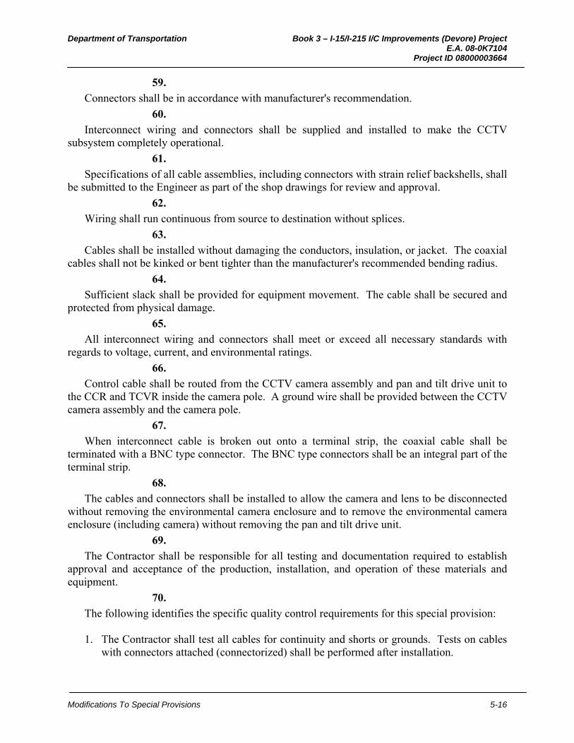
Department of Transportation Book 3 – I-15/I-215 I/C Improvements (Devore) Project E.A. 08-0K7104 Project ID 08000003664
Modifications To Special Provisions 5-16
59.
Connectors shall be in accordance with manufacturer's recommendation.
60.
Interconnect wiring and connectors shall be supplied and installed to make the CCTV subsystem completely operational.
61.
Specifications of all cable assemblies, including connectors with strain relief backshells, shall be submitted to the Engineer as part of the shop drawings for review and approval.
62.
Wiring shall run continuous from source to destination without splices.
63.
Cables shall be installed without damaging the conductors, insulation, or jacket. The coaxial cables shall not be kinked or bent tighter than the manufacturer's recommended bending radius.
64.
Sufficient slack shall be provided for equipment movement. The cable shall be secured and protected from physical damage.
65.
All interconnect wiring and connectors shall meet or exceed all necessary standards with regards to voltage, current, and environmental ratings.
66.
Control cable shall be routed from the CCTV camera assembly and pan and tilt drive unit to the CCR and TCVR inside the camera pole. A ground wire shall be provided between the CCTV camera assembly and the camera pole.
67.
When interconnect cable is broken out onto a terminal strip, the coaxial cable shall be terminated with a BNC type connector. The BNC type connectors shall be an integral part of the terminal strip.
68.
The cables and connectors shall be installed to allow the camera and lens to be disconnected without removing the environmental camera enclosure and to remove the environmental camera enclosure (including camera) without removing the pan and tilt drive unit.
69.
The Contractor shall be responsible for all testing and documentation required to establish approval and acceptance of the production, installation, and operation of these materials and equipment.
70.
The following identifies the specific quality control requirements for this special provision: 1. The Contractor shall test all cables for continuity and shorts or grounds. Tests on cables
with connectors attached (connectorized) shall be performed after installation.
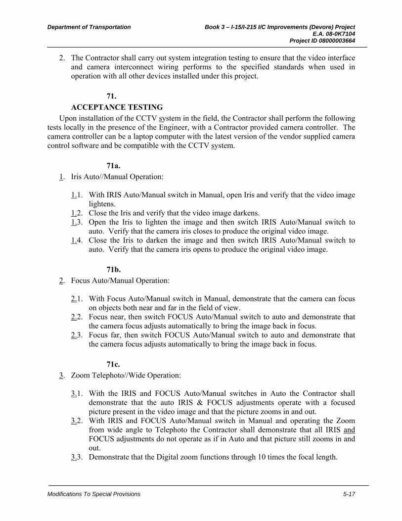
Department of Transportation Book 3 – I-15/I-215 I/C Improvements (Devore) Project E.A. 08-0K7104 Project ID 08000003664
Modifications To Special Provisions 5-17
2. The Contractor shall carry out system integration testing to ensure that the video interface and camera interconnect wiring performs to the specified standards when used in operation with all other devices installed under this project.
71.
ACCEPTANCE TESTING
Upon installation of the CCTV system in the field, the Contractor shall perform the following tests locally in the presence of the Engineer, with a Contractor provided camera controller. The camera controller can be a laptop computer with the latest version of the vendor supplied camera control software and be compatible with the CCTV system.
71a.
1. Iris Auto//Manual Operation:
1.1. With IRIS Auto/Manual switch in Manual, open Iris and verify that the video image lightens.
1.2. Close the Iris and verify that the video image darkens. 1.3. Open the Iris to lighten the image and then switch IRIS Auto/Manual switch to
auto. Verify that the camera iris closes to produce the original video image. 1.4. Close the Iris to darken the image and then switch IRIS Auto/Manual switch to
auto. Verify that the camera iris opens to produce the original video image.
71b.
2. Focus Auto/Manual Operation:
2.1. With Focus Auto/Manual switch in Manual, demonstrate that the camera can focus on objects both near and far in the field of view.
2.2. Focus near, then switch FOCUS Auto/Manual switch to auto and demonstrate that the camera focus adjusts automatically to bring the image back in focus.
2.3. Focus far, then switch FOCUS Auto/Manual switch to auto and demonstrate that the camera focus adjusts automatically to bring the image back in focus.
71c.
3. Zoom Telephoto//Wide Operation:
3.1. With the IRIS and FOCUS Auto/Manual switches in Auto the Contractor shall demonstrate that the auto IRIS & FOCUS adjustments operate with a focused picture present in the video image and that the picture zooms in and out.
3.2. With IRIS and FOCUS Auto/Manual switch in Manual and operating the Zoom from wide angle to Telephoto the Contractor shall demonstrate that all IRIS and FOCUS adjustments do not operate as if in Auto and that picture still zooms in and out.
3.3. Demonstrate that the Digital zoom functions through 10 times the focal length.
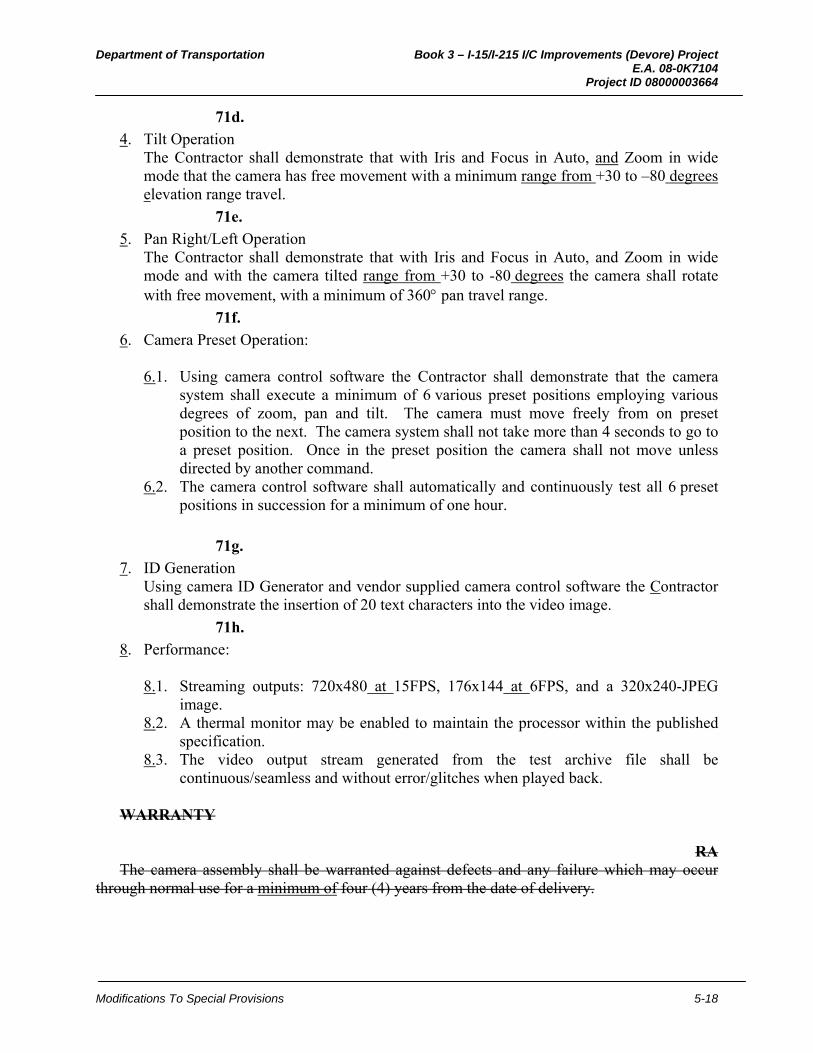
Department of Transportation Book 3 – I-15/I-215 I/C Improvements (Devore) Project E.A. 08-0K7104 Project ID 08000003664
Modifications To Special Provisions 5-18
71d.
4. Tilt Operation The Contractor shall demonstrate that with Iris and Focus in Auto, and Zoom in wide
mode that the camera has free movement with a minimum range from +30 to –80 degrees elevation range travel.
71e.
5. Pan Right/Left Operation The Contractor shall demonstrate that with Iris and Focus in Auto, and Zoom in wide
mode and with the camera tilted range from +30 to -80 degrees the camera shall rotate with free movement, with a minimum of 360 pan travel range.
71f.
6. Camera Preset Operation:
6.1. Using camera control software the Contractor shall demonstrate that the camera system shall execute a minimum of 6 various preset positions employing various degrees of zoom, pan and tilt. The camera must move freely from on preset position to the next. The camera system shall not take more than 4 seconds to go to a preset position. Once in the preset position the camera shall not move unless directed by another command.
6.2. The camera control software shall automatically and continuously test all 6 preset positions in succession for a minimum of one hour.
71g.
7. ID Generation Using camera ID Generator and vendor supplied camera control software the Contractor
shall demonstrate the insertion of 20 text characters into the video image.
71h.
8. Performance:
8.1. Streaming outputs: 720x480 at 15FPS, 176x144 at 6FPS, and a 320x240-JPEG image.
8.2. A thermal monitor may be enabled to maintain the processor within the published specification.
8.3. The video output stream generated from the test archive file shall be continuous/seamless and without error/glitches when played back.
WARRANTY
RA The camera assembly shall be warranted against defects and any failure which may occur
through normal use for a minimum of four (4) years from the date of delivery.

Department of Transportation Book 3 – I-15/I-215 I/C Improvements (Devore) Project E.A. 08-0K7104 Project ID 08000003664
Modifications To Special Provisions 5-1
8. WIRELESS ETHERNET RADIO (WER)
WIRELESS ETHERNET RADIO (WER)
DESCRIPTION
The Wireless Ethernet Radio (WER) Assembly shall include the WER radios, WER antennas and WER interconnect wiring.
WER RADIO
8-9-10, RS*** The Wireless Ethernet Radio (WER) shall provide a wireless serial RSEIA-232 and Ethernet
communication link to stand-alone field elements. The WER shall act as a RSEIA-232 and Ethernet gateway.
Carrier Detect (CD) or Clear to Send (CTS) signal shall be asserted 0.1s +/- 0.01s prior to data being transmitted and shall be de-asserted 0.1s +/-0.01s after the last byte sequence is transmitted.
WER radio minimum requirements:
8-9-10, RS*** 1. Frequency of Operation: 902 – 928 MHz 2. Spread Spectrum: Frequency Hopping and DTS 3. Hopping Channels: 50/Pattern 4. Error Detection: 32bitCRC, ARQ 5. RF Data Rate: 345kbps and 1.384Mbps upgradable to 1.9Mbps 6 Ports: 1 RSEIA-232/RSEIA-485/RSEIA-422, 1 RSEIA-232
Serial Port, 1 Ethernet, 1 USB 7. Serial Baud Rate: 300 baud to 921 kbaud 8. Receiver Sensitivity: -97dBm at 1.384Mbps and -105dBm at 345kpbs 9. Data Encryption: 128 bit AES upgradeable to optional 256 bit AES 10. RF-Power: 100mW to 1W (20-30dBm) programmable in 1dB steps 11. System Gain: 135dB system gain w/unity again antenna 12. Serial Ports: Two RSEIA-232: RxD, TxD, RTS, CTS, DCD, DSR, DTR
RSEIA-422: Tx+, Tx-, Rx+, Rx- RSEIA-485: 4 wire/2wire Baud rate: 300bps to 921kbps
13. Serial Connectors: DB-9F and RJ45 mini USB 14. Sleep Mode: Supported on RSEIA-232 and Remote Wake up 15. USB: USB to Serial routing
USB interface USB Console USB to Ethernet routing Wireless USB to Ethernet Routing
16. Antenna Connector: Reverse Polarity TNC Male 17. Size: 3.75 inches x 2.25 inches x 1.75 inches 18. Ethernet: RJ-45, 10/100 BaseT IEEE 802.3
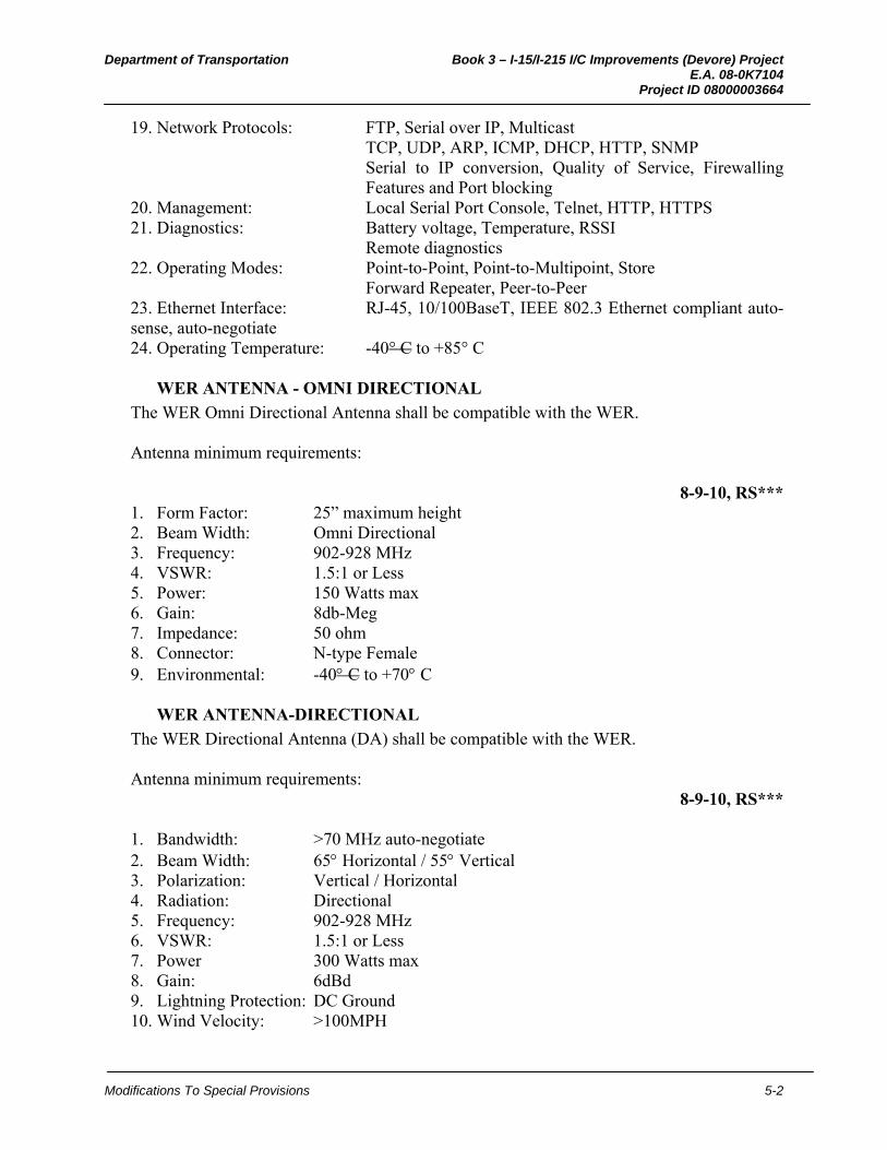
Department of Transportation Book 3 – I-15/I-215 I/C Improvements (Devore) Project E.A. 08-0K7104 Project ID 08000003664
Modifications To Special Provisions 5-2
19. Network Protocols: FTP, Serial over IP, Multicast TCP, UDP, ARP, ICMP, DHCP, HTTP, SNMP Serial to IP conversion, Quality of Service, Firewalling Features and Port blocking
20. Management: Local Serial Port Console, Telnet, HTTP, HTTPS 21. Diagnostics: Battery voltage, Temperature, RSSI
Remote diagnostics 22. Operating Modes: Point-to-Point, Point-to-Multipoint, Store
Forward Repeater, Peer-to-Peer 23. Ethernet Interface: RJ-45, 10/100BaseT, IEEE 802.3 Ethernet compliant auto-sense, auto-negotiate 24. Operating Temperature: -40° C to +85° C
WER ANTENNA - OMNI DIRECTIONAL
The WER Omni Directional Antenna shall be compatible with the WER. Antenna minimum requirements:
8-9-10, RS*** 1. Form Factor: 25” maximum height 2. Beam Width: Omni Directional 3. Frequency: 902-928 MHz 4. VSWR: 1.5:1 or Less 5. Power: 150 Watts max 6. Gain: 8db-Meg 7. Impedance: 50 ohm 8. Connector: N-type Female 9. Environmental: -40 C to +70 C
WER ANTENNA-DIRECTIONAL
The WER Directional Antenna (DA) shall be compatible with the WER. Antenna minimum requirements:
8-9-10, RS*** 1. Bandwidth: >70 MHz auto-negotiate 2. Beam Width: 65 Horizontal / 55 Vertical 3. Polarization: Vertical / Horizontal 4. Radiation: Directional 5. Frequency: 902-928 MHz 6. VSWR: 1.5:1 or Less 7. Power 300 Watts max 8. Gain: 6dBd 9. Lightning Protection: DC Ground 10. Wind Velocity: >100MPH
Department of Transportation Book 3 – I-15/I-215 I/C Improvements (Devore) Project E.A. 08-0K7104 Project ID 08000003664
Modifications To Special Provisions 5-3
11. Impedance: 50 ohm 12. Feed Connection: Reverse Polarity TNC (N-Female) 13. Maximum Length: 41.5" 14. Mounting: For both Polarizations 15. Environmental: -40 C to +70 C
Certificate of Compliance
The Contractor shall provide the Engineer with a Certificate of Compliance from the manufacturer in accordance with NEMA TS1/2 Environmental Requirements for Traffic Control Equipment.
WER INTERCONNECT WIRING
The WER interconnect wiring consists of the coaxial and CAT 5E cables and shall be installed as shown on the plans, as specified in these special provisions and as recommended by the manufacturer.
All connectors shall be in accordance with the manufacturer’s recommendation. All connectors installed outside the enclosure shall be weather proof and watertight. Weather proofing and water sealing shall be included, provided and installed.
Specifications of all cable assemblies, including connectors with strain relief backshells, shall be submitted to the Engineer as part of the shop drawings for review and approval.
Interconnect cabling and wiring shall run continuous from the source to destination without splices.
Three feet of slack shall be provided for equipment movement. All cabling shall be secured and protected from physical damage.
All interconnect wiring and connectors shall meet or exceed all necessary standards with regards to voltage, current and environmental ratings.
The Contractor shall be responsible for all testing and documentation required to establish approval and acceptance of the production, installation and operation of these materials and equipment.
The Contractor shall test all cables for continuity and shorts or grounds. Tests on cables with connectors attached (connectorized) shall be performed after installation.
The Contractor shall carry out system integration testing to ensure that the interfaces and all interconnect wiring and cabling perform to the specified standards when used in operation with all other devices installed under the contract.
The Contractor shall configure interconnect wiring and cabling at all locations shown on the project plans.
Coaxial cable
The antenna coaxial cables to be used for 5.7 GHz and 900 MHz RF connections shall be of 50 ohms impedance, low loss, flexible, rugged and UV resistant, and shall have greater than 90 dB RF shielding. The coaxial cable shall have a minimum bend radius of 1”. Attenuation for 900 MHz shall not exceed 15 dB /100 m. Attenuation for 5.7GHz shall not exceed 40 dB /100 m.
Department of Transportation Book 3 – I-15/I-215 I/C Improvements (Devore) Project E.A. 08-0K7104 Project ID 08000003664
Modifications To Special Provisions 5-1
9. DRAINAGE INLET PROTECTION
07-XXX ALL NEW RBS**
March 28, 2012
USE WITH 2006 STANDARDS.
NOTE: This nSSP is based on the SSP 07-490_English_A03-13-09.
Use as a permanent sediment control to filter or settle sediment-laden runoff before discharge into a storm drainage system at drainage inlets in unpaved areas.
Include a detail for the drainage inlet protection in the plans. The detail is based on the temporary drainage inlet protection (Type 4A).
Use BEES item 074061A “Drainage Inlet Protection”
Areas of application must be shown on the plans
10-1.__ DRAINAGE INLET PROTECTION GENERAL
Summary
1
This work includes constructing and maintaining drainage inlet protection as shown on the plans, as specified in these special provisions, and as directed by the Engineer.
Submittals
2
Submit a Certificate of Compliance as specified in Section 6-1.07, "Certificates of Compliance" of the Standard Specifications for:
1. Rolled erosion control products 2. Fiber rolls 3. Fasteners
MATERIALS Rolled Erosion Control Products
3
RECP must be a long-term, degradable, open-weave textile manufactured or fabricated into rolls designed to reduce soil erosion and assist in the growth, establishment, and protection of vegetation. RECP must conform to the classification system established by the Erosion Control Technology Council. RECPs must be:
1. Netting must be made of coconut fiber woven into a matrix. Netting must comply with
the requirements shown in the following table:
Department of Transportation Book 3 – I-15/I-215 I/C Improvements (Devore) Project E.A. 08-0K7104 Project ID 08000003664
Modifications To Special Provisions 5-2
Netting
Property Type
Requirements Test
Method
Classification -- ECTC Type 4 --
Minimum thickness A, B, C 0.30 inch --
Roll width A, B, C 72–158 inches --
Matrix A, B, C 100% woven coir (coconut
fiber) --
Universal Soil Loss Equation (USLE) C-Factor for a 1:1 (H:V) unvegetated slope
A, B, C ≤ 0.25 --
Maximum shear stress A B C
2.25 psf 4.4 psf 4.6 psf
ASTM D 6460
Minimum tensile strength A, B, C 125 psf ASTM D
5035
Functional longevity A, B, C 36 months --
Average open area A B C
63 ± 5% 48 ± 5% 38 ± 5%
--
Minimum weight of fabric A B C
11.8 oz/sq yd 20 oz/sq yd 26 oz/sq yd
ASTM D 3776
2. Erosion control blanket must be made of processed natural fibers that are mechanically,
structurally, or chemically bound together to form a continuous matrix that is surrounded by 2 natural nets. The erosion control blanket must comply with the requirements shown in the following table:
Erosion Control Blanket
Property Type
Requirements Test
Method
Classification -- ECTC Type 2D --
Net type A, B, C Natural --
Number of nets A, B, C Double --
Minimum roll width A, B, C 72 inches --
Matrix
A B C
70/30% (straw/coconut fiber) 100% woven coir (coconut fiber) Wood excelsior (80 percent of the
fiber 6 inches or longer)
--
Universal soil loss equation (USLE) C-Factor for a 2:1 (H:V) unvegetated slope.
A, B, C ≤ 0.20 --
Department of Transportation Book 3 – I-15/I-215 I/C Improvements (Devore) Project E.A. 08-0K7104 Project ID 08000003664
Modifications To Special Provisions 5-3
Maximum shear stress A, B, C 1.75 psf ASTM D
6460
Minimum tensile strength A, B, C 75 psf ASTM D
5035
Functional longevity A, B, C 12 months
--
Fiber Rolls
4
Fiber roll must have a minimum functional longevity of 120 days and comply with the following requirements:
1. Type A fiber roll must be fabricated from an erosion control blanket rolled along its
width. Secure with natural fiber twine at 6-foot intervals, and 6 inches from each end. Fiber roll size must comply with either one of the following: 1.1. 8 to 10 inches in diameter, 10 to 20 feet long, and at least 0.5 lb/ft 1.2. 10 to 12 inches in diameter, at least 10 feet long, and at least 2 lb/ft
2. Type B fiber roll must be a premanufactured roll filled with rice or wheat straw, wood excelsior, or coconut fiber. Rolls must be covered with biodegradable jute, sisal, or coir fiber netting secured tightly at each end. Fiber roll size must comply with either one of the following: 2.1. 8 to 10 inches in diameter, 10 to 20 feet long, and at least 1.1 lb/ft 2.2. 10 to 12 inches in diameter, at least 10 feet long, and at least 3 lb/ft
Fasteners
5
Wood stakes must be untreated fir, redwood, cedar, or pine and cut from sound timber. Ends must be pointed for driving into the ground. Notched stakes must be at least 1 by 2 by 24 inches in size. Stakes without notches must be at least 1 by 1 by 24 inches.
6
Steel staples must be a minimum of 11 gauge, 6-inch U-shaped staple with a 1-inch crown. Provide heavier gauge and greater length if required by the site conditions. You may use an alternative attachment device such as a 100 percent biodegradable fastener to install RECP instead of staples.
7
Rope to fasten fiber rolls and compost socks must be 1/4-inch diameter and biodegradable such as sisal or manila.

Department of Transportation Book 3 – I-15/I-215 I/C Improvements (Devore) Project E.A. 08-0K7104 Project ID 08000003664
Modifications To Special Provisions 5-4
CONSTRUCTION
8* Replace "erosion control materials" with other final stabilization as described in the specifications.
For drainage inlet protection at drainage inlets in unpaved areas: 1. Before installing the drainage inlet protection, ensure the subgrade has been graded
smooth and has no depressed void areas. The subgrade must be free from obstructions, such as tree roots, projecting stones, or foreign matter greater than 1 inch in diameter
2. Before installing erosion control materials, install drainage inlet protection. 3. Install RECP:
3.1. Fasten RECP to the surface with staples and embed in a trench adjacent to the drainage inlet
3.2. Anchor the perimeter edge of the RECP in a trench and tamp
4. Install fiber roll:
4.1. Fasten with wood stakes every 24 inches along the length of the fiber roll 4.2. Fasten the ends of the fiber roll by placing a stake 6 inches from the end of the roll 4.3. Drive stakes into the soil so that the top of the stake is less then 2 inches above the
top of the fiber roll 4.4. Place excess soil from excavation of the key trenches uphill of the installed fiber
rolls
Maintenance
9
Repair or replace drainage inlet protection within 24 hours of discovering the damage or longer if allowed by the Engineer.
10
If your vehicles, equipment, or activities disturb or displace drainage inlet protection, repair drainage inlet protection at your expense.
11
Maintain drainage inlet protection in a manner that provides sediment holding capacity and reduces runoff velocities as follows:
1. Remove sediment from drainage inlet protection when sediment is in excess of 2 inches
above the surface of the RECP 2. Repair or adjust the fiber roll or RECP when rills or other evidence of concentrated
runoff occur beneath the drainage inlet protection 3. Repair or replace the fiber roll or RECP when it becomes split, torn, or unraveled 4. Add stakes when the fiber roll slumps or sags 5. Replace broken or split wood stakes 6. Remove sediment deposits, trash, and debris from drainage inlet protection as needed or
when directed by the Engineer. Trash and debris shall be removed and disposed of in

Department of Transportation Book 3 – I-15/I-215 I/C Improvements (Devore) Project E.A. 08-0K7104 Project ID 08000003664
Modifications To Special Provisions 5-5
accordance with the provisions in Section 7-1.13, "Disposal of Material Outside the Highway Right of Way," of the Standard Specifications. If removed sediment is deposited within project limits, it must be stabilized and not exposed to erosion by wind or water
MEASUREMENT AND PAYMENT
12
Quantities of drainage inlet protection is determined from actual count in place.
13
The contract unit price paid for drainage inlet protection includes full compensation for furnishing all labor, materials, tools, equipment, and incidentals, and for doing all the work involved in constructing the drainage inlet protection, complete in place, as shown on the plans, as specified in the Standard Specifications and these special provisions, and as directed by the Engineer.

Department of Transportation Book 3 – I-15/I-215 I/C Improvements (Devore) Project E.A. 08-0K7104 Project ID 08000003664
Modifications To Special Provisions 5-1
10. FLARED END SECTION PROTECTION
07-XXX ALL NEW RBS**
March 28, 2012
USE WITH 2006 STANDARDS.
Use as a permanent sediment control to filter or settle sediment-laden runoff surrounding flared end sections located at the inlet and outlet of culverts.
Include a detail for the flared end section protection in the plans.
Use BEES item 074064A “Flared End Section Protection”
Areas of application must be shown on the plans
10-1.__ FLARED END SECTION PROTECTION GENERAL
Summary
1
This work includes constructing and maintaining flared end section protection as shown on the plans, as specified in these special provisions, and as directed by the Engineer.
Submittals
2
Submit a Certificate of Compliance as specified in Section 6-1.07, "Certificates of Compliance" of the Standard Specifications for:
1. Rolled erosion control products 2. Fiber rolls 3. Fasteners
MATERIALS Rolled Erosion Control Products
3
RECP must be a long-term, degradable, open-weave textile manufactured or fabricated into rolls designed to reduce soil erosion and assist in the growth, establishment, and protection of vegetation. RECP must conform to the classification system established by the Erosion Control Technology Council. RECPs must be:
1. Netting must be made of coconut fiber woven into a matrix. Netting must comply with
the requirements shown in the following table: Netting
Property Type
Requirements Test
Method
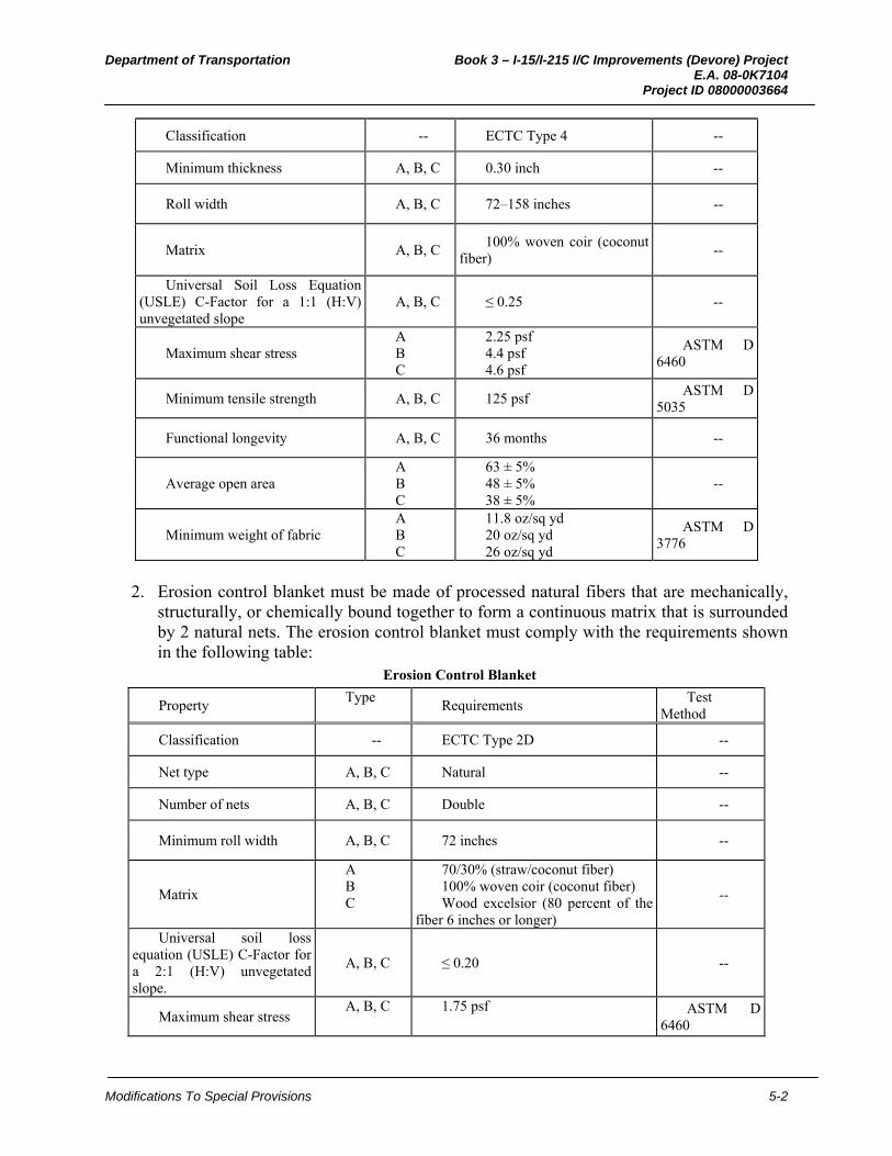
Department of Transportation Book 3 – I-15/I-215 I/C Improvements (Devore) Project E.A. 08-0K7104 Project ID 08000003664
Modifications To Special Provisions 5-2
Classification -- ECTC Type 4 --
Minimum thickness A, B, C 0.30 inch --
Roll width A, B, C 72–158 inches --
Matrix A, B, C 100% woven coir (coconut
fiber) --
Universal Soil Loss Equation (USLE) C-Factor for a 1:1 (H:V) unvegetated slope
A, B, C ≤ 0.25 --
Maximum shear stress A B C
2.25 psf 4.4 psf 4.6 psf
ASTM D 6460
Minimum tensile strength A, B, C 125 psf ASTM D
5035
Functional longevity A, B, C 36 months --
Average open area A B C
63 ± 5% 48 ± 5% 38 ± 5%
--
Minimum weight of fabric A B C
11.8 oz/sq yd 20 oz/sq yd 26 oz/sq yd
ASTM D 3776
2. Erosion control blanket must be made of processed natural fibers that are mechanically,
structurally, or chemically bound together to form a continuous matrix that is surrounded by 2 natural nets. The erosion control blanket must comply with the requirements shown in the following table:
Erosion Control Blanket
Property Type
Requirements Test
Method
Classification -- ECTC Type 2D --
Net type A, B, C Natural --
Number of nets A, B, C Double --
Minimum roll width A, B, C 72 inches --
Matrix
A B C
70/30% (straw/coconut fiber) 100% woven coir (coconut fiber) Wood excelsior (80 percent of the
fiber 6 inches or longer)
--
Universal soil loss equation (USLE) C-Factor for a 2:1 (H:V) unvegetated slope.
A, B, C ≤ 0.20 --
Maximum shear stress A, B, C 1.75 psf ASTM D
6460
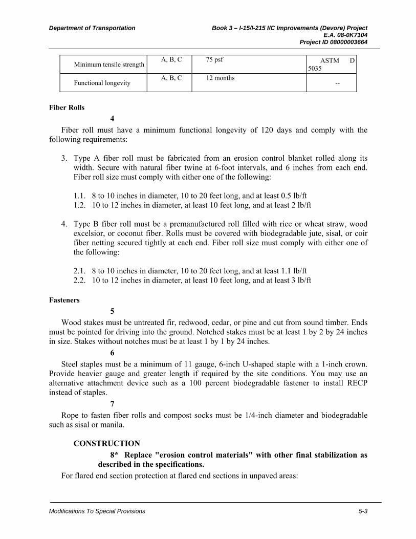
Department of Transportation Book 3 – I-15/I-215 I/C Improvements (Devore) Project E.A. 08-0K7104 Project ID 08000003664
Modifications To Special Provisions 5-3
Minimum tensile strength A, B, C 75 psf ASTM D
5035
Functional longevity A, B, C 12 months
--
Fiber Rolls
4
Fiber roll must have a minimum functional longevity of 120 days and comply with the following requirements:
3. Type A fiber roll must be fabricated from an erosion control blanket rolled along its
width. Secure with natural fiber twine at 6-foot intervals, and 6 inches from each end. Fiber roll size must comply with either one of the following: 1.1. 8 to 10 inches in diameter, 10 to 20 feet long, and at least 0.5 lb/ft 1.2. 10 to 12 inches in diameter, at least 10 feet long, and at least 2 lb/ft
4. Type B fiber roll must be a premanufactured roll filled with rice or wheat straw, wood excelsior, or coconut fiber. Rolls must be covered with biodegradable jute, sisal, or coir fiber netting secured tightly at each end. Fiber roll size must comply with either one of the following: 2.1. 8 to 10 inches in diameter, 10 to 20 feet long, and at least 1.1 lb/ft 2.2. 10 to 12 inches in diameter, at least 10 feet long, and at least 3 lb/ft
Fasteners
5
Wood stakes must be untreated fir, redwood, cedar, or pine and cut from sound timber. Ends must be pointed for driving into the ground. Notched stakes must be at least 1 by 2 by 24 inches in size. Stakes without notches must be at least 1 by 1 by 24 inches.
6
Steel staples must be a minimum of 11 gauge, 6-inch U-shaped staple with a 1-inch crown. Provide heavier gauge and greater length if required by the site conditions. You may use an alternative attachment device such as a 100 percent biodegradable fastener to install RECP instead of staples.
7
Rope to fasten fiber rolls and compost socks must be 1/4-inch diameter and biodegradable such as sisal or manila.
CONSTRUCTION
8* Replace "erosion control materials" with other final stabilization as described in the specifications.
For flared end section protection at flared end sections in unpaved areas:

Department of Transportation Book 3 – I-15/I-215 I/C Improvements (Devore) Project E.A. 08-0K7104 Project ID 08000003664
Modifications To Special Provisions 5-4
5. Before installing the flared end section protection, ensure the subgrade has been graded smooth and has no depressed void areas. The subgrade must be free from obstructions, such as tree roots, projecting stones, or foreign matter greater than 1 inch in diameter
6. Before installing erosion control materials, install flared end section protection. 7. Install RECP:
3.1. Fasten RECP to the surface with staples and embed in a trench adjacent to the flared end section
3.2. Anchor the perimeter edge of the RECP in a trench and tamp
8. Install fiber roll:
4.1. Fasten with wood stakes every 24 inches along the length of the fiber roll 4.2. Fasten the ends of the fiber roll by placing a stake 6 inches from the end of the roll 4.3. Drive stakes into the soil so that the top of the stake is less then 2 inches above the
top of the fiber roll 4.4. Place excess soil from excavation of the key trenches uphill of the installed fiber
rolls
Maintenance
9
Repair or replace flared end section protection within 24 hours of discovering the damage or longer if allowed by the Engineer.
10
If your vehicles, equipment, or activities disturb or displace flared end section protection, repair flared end section protection at your expense.
11
Maintain flared end section protection in a manner that provides sediment holding capacity and reduces runoff velocities as follows:
7. Remove sediment from flared end section protection when sediment is in excess of 2
inches above the surface of the RECP 8. Repair or adjust the fiber roll or RECP when rills or other evidence of concentrated
runoff occur beneath the flared end section protection 9. Repair or replace the fiber roll or RECP when it becomes split, torn, or unraveled 10. Add stakes when the fiber roll slumps or sags 11. Replace broken or split wood stakes 12. Remove sediment deposits, trash, and debris from flared end section protection as needed
or when directed by the Engineer. Trash and debris shall be removed and disposed of in accordance with the provisions in Section 7-1.13, "Disposal of Material Outside the Highway Right of Way," of the Standard Specifications. If removed sediment is deposited within project limits, it must be stabilized and not exposed to erosion by wind or water

Department of Transportation Book 3 – I-15/I-215 I/C Improvements (Devore) Project E.A. 08-0K7104 Project ID 08000003664
Modifications To Special Provisions 5-5
MEASUREMENT AND PAYMENT
12
Quantities of flared end section protection is determined from actual count in place.
13
The contract unit price paid for flared end section protection includes full compensation for furnishing all labor, materials, tools, equipment, and incidentals, and for doing all the work involved in constructing the flared end section protection, complete in place, as shown on the plans, as specified in the Standard Specifications and these special provisions, and as directed by the Engineer.

Department of Transportation Book 3 – I-15/I-215 I/C Improvements (Devore) Project E.A. 08-0K7104 Project ID 08000003664
Modifications To Special Provisions 5-1
11. DRAINAGE OUTLET PROTECTION 07-XXX ALL NEW
RBS** March 28, 2012
USE WITH 2006 STANDARDS.
Use as a permanent sediment control to filter or settle sediment-laden runoff before discharge into unlined conveyances, swales, or receiving waters.
Include a detail for the drainage outlet protection in the plans.
Use BEES item 074063A “Drainage Outlet Protection”
Areas of application must be shown on the plans
10-1.__ DRAINAGE OUTLET PROTECTION GENERAL
Summary
1
This work includes constructing and maintaining drainage outlet protection as shown on the plans, as specified in these special provisions, and as directed by the Engineer.
Submittals
2
Submit a Certificate of Compliance as specified in Section 6-1.07, "Certificates of Compliance" of the Standard Specifications for:
1. Rolled erosion control products 2. Fiber rolls 3. Fasteners
MATERIALS Rolled Erosion Control Products
3
RECP must be a long-term, degradable, open-weave textile manufactured or fabricated into rolls designed to reduce soil erosion and assist in the growth, establishment, and protection of vegetation. RECP must conform to the classification system established by the Erosion Control Technology Council. RECPs must be:
1. Netting must be made of coconut fiber woven into a matrix. Netting must comply with
the requirements shown in the following table: Netting
Property Type
Requirements Test
Method

Department of Transportation Book 3 – I-15/I-215 I/C Improvements (Devore) Project E.A. 08-0K7104 Project ID 08000003664
Modifications To Special Provisions 5-2
Classification -- ECTC Type 4 --
Minimum thickness A, B, C 0.30 inch --
Roll width A, B, C 72–158 inches --
Matrix A, B, C 100% woven coir (coconut
fiber) --
Universal Soil Loss Equation (USLE) C-Factor for a 1:1 (H:V) unvegetated slope
A, B, C ≤ 0.25 --
Maximum shear stress A B C
2.25 psf 4.4 psf 4.6 psf
ASTM D 6460
Minimum tensile strength A, B, C 125 psf ASTM D
5035
Functional longevity A, B, C 36 months --
Average open area A B C
63 ± 5% 48 ± 5% 38 ± 5%
--
Minimum weight of fabric A B C
11.8 oz/sq yd 20 oz/sq yd 26 oz/sq yd
ASTM D 3776
2. Erosion control blanket must be made of processed natural fibers that are mechanically,
structurally, or chemically bound together to form a continuous matrix that is surrounded by 2 natural nets. The erosion control blanket must comply with the requirements shown in the following table:
Erosion Control Blanket
Property Type
Requirements Test
Method
Classification -- ECTC Type 2D --
Net type A, B, C Natural --
Number of nets A, B, C Double --
Minimum roll width A, B, C 72 inches --
Matrix
A B C
70/30% (straw/coconut fiber) 100% woven coir (coconut fiber) Wood excelsior (80 percent of the
fiber 6 inches or longer)
--
Universal soil loss equation (USLE) C-Factor for a 2:1 (H:V) unvegetated slope.
A, B, C ≤ 0.20 --
Maximum shear stress A, B, C 1.75 psf ASTM D
6460
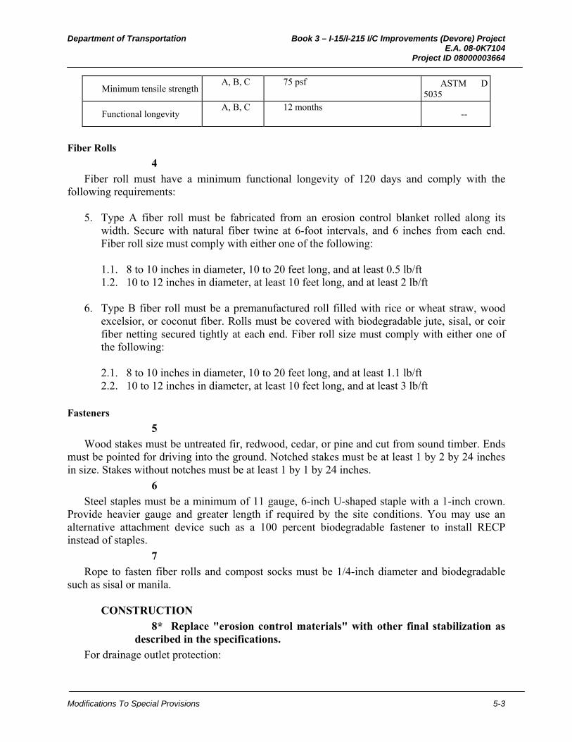
Department of Transportation Book 3 – I-15/I-215 I/C Improvements (Devore) Project E.A. 08-0K7104 Project ID 08000003664
Modifications To Special Provisions 5-3
Minimum tensile strength A, B, C 75 psf ASTM D
5035
Functional longevity A, B, C 12 months
--
Fiber Rolls
4
Fiber roll must have a minimum functional longevity of 120 days and comply with the following requirements:
5. Type A fiber roll must be fabricated from an erosion control blanket rolled along its
width. Secure with natural fiber twine at 6-foot intervals, and 6 inches from each end. Fiber roll size must comply with either one of the following: 1.1. 8 to 10 inches in diameter, 10 to 20 feet long, and at least 0.5 lb/ft 1.2. 10 to 12 inches in diameter, at least 10 feet long, and at least 2 lb/ft
6. Type B fiber roll must be a premanufactured roll filled with rice or wheat straw, wood excelsior, or coconut fiber. Rolls must be covered with biodegradable jute, sisal, or coir fiber netting secured tightly at each end. Fiber roll size must comply with either one of the following: 2.1. 8 to 10 inches in diameter, 10 to 20 feet long, and at least 1.1 lb/ft 2.2. 10 to 12 inches in diameter, at least 10 feet long, and at least 3 lb/ft
Fasteners
5
Wood stakes must be untreated fir, redwood, cedar, or pine and cut from sound timber. Ends must be pointed for driving into the ground. Notched stakes must be at least 1 by 2 by 24 inches in size. Stakes without notches must be at least 1 by 1 by 24 inches.
6
Steel staples must be a minimum of 11 gauge, 6-inch U-shaped staple with a 1-inch crown. Provide heavier gauge and greater length if required by the site conditions. You may use an alternative attachment device such as a 100 percent biodegradable fastener to install RECP instead of staples.
7
Rope to fasten fiber rolls and compost socks must be 1/4-inch diameter and biodegradable such as sisal or manila.
CONSTRUCTION
8* Replace "erosion control materials" with other final stabilization as described in the specifications.
For drainage outlet protection:
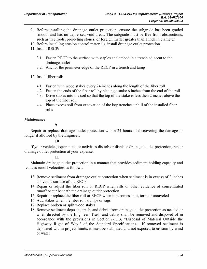
Department of Transportation Book 3 – I-15/I-215 I/C Improvements (Devore) Project E.A. 08-0K7104 Project ID 08000003664
Modifications To Special Provisions 5-4
9. Before installing the drainage outlet protection, ensure the subgrade has been graded smooth and has no depressed void areas. The subgrade must be free from obstructions, such as tree roots, projecting stones, or foreign matter greater than 1 inch in diameter
10. Before installing erosion control materials, install drainage outlet protection. 11. Install RECP:
3.1. Fasten RECP to the surface with staples and embed in a trench adjacent to the drainage outlet
3.2. Anchor the perimeter edge of the RECP in a trench and tamp
12. Install fiber roll:
4.1. Fasten with wood stakes every 24 inches along the length of the fiber roll 4.2. Fasten the ends of the fiber roll by placing a stake 6 inches from the end of the roll 4.3. Drive stakes into the soil so that the top of the stake is less then 2 inches above the
top of the fiber roll 4.4. Place excess soil from excavation of the key trenches uphill of the installed fiber
rolls
Maintenance
9
Repair or replace drainage outlet protection within 24 hours of discovering the damage or longer if allowed by the Engineer.
10
If your vehicles, equipment, or activities disturb or displace drainage outlet protection, repair drainage outlet protection at your expense.
11
Maintain drainage outlet protection in a manner that provides sediment holding capacity and reduces runoff velocities as follows:
13. Remove sediment from drainage outlet protection when sediment is in excess of 2 inches
above the surface of the RECP 14. Repair or adjust the fiber roll or RECP when rills or other evidence of concentrated
runoff occur beneath the drainage outlet protection 15. Repair or replace the fiber roll or RECP when it becomes split, torn, or unraveled 16. Add stakes when the fiber roll slumps or sags 17. Replace broken or split wood stakes 18. Remove sediment deposits, trash, and debris from drainage outlet protection as needed or
when directed by the Engineer. Trash and debris shall be removed and disposed of in accordance with the provisions in Section 7-1.13, "Disposal of Material Outside the Highway Right of Way," of the Standard Specifications. If removed sediment is deposited within project limits, it must be stabilized and not exposed to erosion by wind or water
Department of Transportation Book 3 – I-15/I-215 I/C Improvements (Devore) Project E.A. 08-0K7104 Project ID 08000003664
Modifications To Special Provisions 5-5
MEASUREMENT AND PAYMENT
12
Quantities of drainage outlet protection is determined from actual count in place.
13
The contract unit price paid for drainage outlet protection includes full compensation for furnishing all labor, materials, tools, equipment, and incidentals, and for doing all the work involved in constructing the drainage outlet protection, complete in place, as shown on the plans, as specified in the Standard Specifications and these special provisions, and as directed by the Engineer.
Department of Transportation Book 3 – I-15/I-215 I/C Improvements (Devore) Project E.A. 08-0K7104 Project ID 08000003664
Modifications To Special Provisions 5-1
12. CHECK DAM 07-XXX ALL NEW
RBS** March 28, 2012
USE WITH 2006 STANDARDS.
NOTE: This nSSP is based on the 07-415_E_A08-01-08 SSP
Use with erosion control blanket as a permanent sediment control structure in ditches and swales to trap and detain sediment in concentrated flows of storm water runoff. Check dams reduce scour and channel erosion by reducing flow velocity.
Use with SSP 20-010 Erosion Control Blanket or other RECP or TRM used as a ditch and swale lining.
Use BEES item 074062A “Check Dam”
Areas of application must be shown on the plans
10-1.__ CHECK DAM GENERAL
Summary
1
This work includes constructing and maintaining check dam as shown on the plans, as specified in these special provisions, and as directed by the Engineer.
Submittals
2
Submit a Certificate of Compliance as specified in Section 6-1.07, "Certificates of Compliance" of the Standard Specifications for:
1. Fiber rolls 2. Fasteners
MATERIALS Fiber Rolls
4
Fiber roll must have a minimum functional longevity of 120 days and comply with the following requirements:
7. Type A fiber roll must be fabricated from an erosion control blanket rolled along its
width. Secure with natural fiber twine at 6-foot intervals, and 6 inches from each end. Fiber roll size must comply with either one of the following: 1.1. 8 to 10 inches in diameter, 10 to 20 feet long, and at least 0.5 lb/ft

Department of Transportation Book 3 – I-15/I-215 I/C Improvements (Devore) Project E.A. 08-0K7104 Project ID 08000003664
Modifications To Special Provisions 5-2
1.2. 10 to 12 inches in diameter, at least 10 feet long, and at least 2 lb/ft
8. Type B fiber roll must be a premanufactured roll filled with rice or wheat straw, wood excelsior, or coconut fiber. Rolls must be covered with biodegradable jute, sisal, or coir fiber netting secured tightly at each end. Fiber roll size must comply with either one of the following: 2.1. 8 to 10 inches in diameter, 10 to 20 feet long, and at least 1.1 lb/ft 2.2. 10 to 12 inches in diameter, at least 10 feet long, and at least 3 lb/ft
Fasteners
5
Wood stakes must be untreated fir, redwood, cedar, or pine and cut from sound timber. Ends must be pointed for driving into the ground. Notched stakes must be at least 1 by 2 by 24 inches in size. Stakes without notches must be at least 1 by 1 by 24 inches.
7
Rope to fasten fiber rolls and compost socks must be 1/4-inch diameter and biodegradable such as sisal or manila.
CONSTRUCTION
8
Construct check dams no more than 90 days before project completion.
9
Before installing the flared end section protection, ensure the subgrade has been graded smooth and has no depressed void areas. The subgrade must be free from obstructions, such as tree roots, projecting stones, or foreign matter greater than 1 inch in diameter.
10* Replace "erosion control blanket" if another rolled erosion control product (RECP) is described such as Jute Mesh, Coir Netting, or turf reinforcement mat (TRM).
Check dams must be: 1. Installed after the application of erosion control blanket in the ditch or swale 2. Placed approximately perpendicular to the centerline of the ditch or drainage line 3. Installed with sufficient spillway depth to prevent flanking of concentrated flow around
the ends of the check dam
11
Fiber rolls for check dams must be: 1. Fastened with rope and notched wood stakes. 2. Installed by driving stakes into the soil until the notch is even with the top of the fiber roll 3. Installed by lacing the rope between stakes and over the fiber roll. Knot the rope at each
stake

Department of Transportation Book 3 – I-15/I-215 I/C Improvements (Devore) Project E.A. 08-0K7104 Project ID 08000003664
Modifications To Special Provisions 5-3
4. Tightened by driving the stakes further into the soil forcing the fiber roll against the surface of the ditch or drainage line
Maintenance
12
Repair or replace check dam within 24 hours of discovering the damage or longer if allowed by the Engineer.
13
If your vehicles, equipment, or activities disturb or displace flared end section protection, repair check damat your expense.
14
Maintain check dam in a manner that provides sediment holding capacity and reduces runoff velocities as follows:
19. Remove sediment from check dam when sediment is in excess of 1/3 the height of the
fiber roll 20. Repair or adjust the fiber roll when rills or other evidence of concentrated runoff occur
beneath the check dam 21. Repair or replace the fiber roll when it becomes split, torn, or unraveled 22. Add stakes when the fiber roll slumps or sags 23. Replace broken or split wood stakes 24. Remove sediment deposits, trash, and debris from check dam as needed or when directed
by the Engineer. Trash and debris shall be removed and disposed of in accordance with the provisions in Section 7-1.13, "Disposal of Material Outside the Highway Right of Way," of the Standard Specifications. If removed sediment is deposited within project limits, it must be stabilized and not exposed to erosion by wind or water
MEASUREMENT AND PAYMENT
15
Check dam is measured by the linear foot along the centerline of the check dams. Where fiber rolls are joined and overlapped, the overlap is measured as a single installed check dam.
16. Do not "full comp" erosion control blanket, RECP, or TRM.
The contract price paid per linear foot for check dam includes full compensation for furnishing all labor, materials, tools, equipment, and incidentals, and for doing all the work involved in constructing the check dams, complete in place, as shown on the plans, as specified in the Standard Specifications and these special provisions, and as directed by the Engineer.