Applicable solder wire diameter 0.3 ~ 0.8 mm User’s manual...
12
BON BON BON BON-8103 8103 8103 8103/8203 8203 8203 8203 V-cut solder machine Applicable solder wire diameter 0.3 ~ 0.8 mm User’s manual Preparation in June 2017 The 2 nd edition JAPAN BONKOTE CO., LTD. V-SOLDER
-
Upload
nguyenphuc -
Category
Documents
-
view
243 -
download
0
Transcript of Applicable solder wire diameter 0.3 ~ 0.8 mm User’s manual...

BONBONBONBON----8103810381038103////8203820382038203
V-cut solder machine
Applicable solder wire diameter 0.3 ~ 0.8 mm
User’s manual
Preparation in June 2017
The 2nd edition
JAPAN BONKOTE CO., LTD.
V-SOLDER
ContentsContentsContentsContents pagepagepagepage
1. Preface ·························································································· 1
2. Notes for safety ··············································································· 1
3. Notes for installation and use ··························································· 2
4. How to use V-cut solder machine
(A) Contents and name ····································································· 3
(B) How to set solder wire ································································· 4
(C) Depth of V-groove and adjustment ················································ 6
(D) Cleaning ·················································································· 7
5. Specifications ················································································· 8
6. Trouble shooting ············································································· 8
7. Guarantee and After sales service ···················································· 9
1
1. Preface
� Thank you very much for purchasing the V-cut solder machine.
� The V-cut solder machine is effective to prevent solder balls & flux scattering
by making V-groove onto a solder wire.
� If your solder wire originally have solder ball prevention effect, this machine
may not provide you with a sufficient effect.
� Read below “ 2. Notes for safety ” before use.
� Keep this manual after read.
2. Notes for safety
BeBeBeBe sure to read this manual before use the machine.sure to read this manual before use the machine.sure to read this manual before use the machine.sure to read this manual before use the machine.
� Never touch the machine with wet hands.
� Never dampen the machine with water or liquid.
� Do not overhaul this machine.
! CAUTION !

2
3. Notes for installation and use
For safety, For safety, For safety, For safety, make sure to observe the following matters.make sure to observe the following matters.make sure to observe the following matters.make sure to observe the following matters.
� This machine is designed with ground specification. For safety, be sure to use a
grounded electrical outlet.
If you do not have such outlet, install it separately.
� Do not place where the machine would be exposed such as too much moisture,
direct sunshine, much dust and vibration.
� Be sure to pull out the power plug when the machine is not used.
� Be sure to grab the power plug when plugging or unplugging.
� Please check your using voltage before use.
� Before adjustment and cleaning of V-blade, Guide pulley and so on, be sure to
turn the power off and pull out the power plug from the electrical outlet.
� Do not use the machine for purpose other than the original purpose.
� Never touch V-blade during the operation.
� Please use single-core solder wire in order to obtain sufficient effect.
� Be sure to make V-groove just before the soldering work in order to obtain
sufficient effect.
� This machine is designed for micro fine solder wire exclusive use. Strong shock
or rough handling may cause setting and adjustment trouble and reduction of
the effect.
� Default of adjustment lever setting is DIA.0.5 mm when no request at
ordering.

3
4. How to use
(A) Contents and Name
FootswitchFootswitchFootswitchFootswitch
3P power cable3P power cable3P power cable3P power cable
BS1363 plug forBS1363 plug forBS1363 plug forBS1363 plug for
220VAC220VAC220VAC220VAC
Reel Reel Reel Reel shaftshaftshaftshaft
Power switchPower switchPower switchPower switch
(back side)(back side)(back side)(back side)
BodyBodyBodyBody
Protection coverProtection coverProtection coverProtection coverVVVV----bladebladebladeblade
Guide pulleyGuide pulleyGuide pulleyGuide pulley
Adjustment leverAdjustment leverAdjustment leverAdjustment lever
Cleaner pinCleaner pinCleaner pinCleaner pin
Wire Wire Wire Wire guide nozzleguide nozzleguide nozzleguide nozzle
3 mm3 mm3 mm3 mm
Hexangular wrenchHexangular wrenchHexangular wrenchHexangular wrench
3 mm3 mm3 mm3 mm
Hexangular wrenchHexangular wrenchHexangular wrenchHexangular wrench

4
(B) How to set up and adjust solder wire diameter
1) Loosen the screw of Guide pulley with a
3 mm hexangular wrench.
2) Set the adjustment lever to your desired
positon manually.
※ Applicable solder wire diameter:
DIA. 0.3 ~ 0.8 mm
3) Tighten the screw of Guide pulley with a
3 mm hexangular wrench.
5
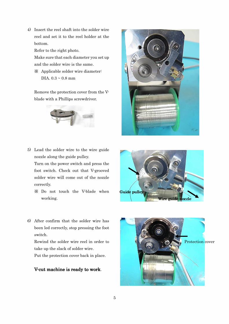
4) Insert the reel shaft into the solder wire
reel and set it to the reel holder at the
bottom.
Refer to the right photo.
Make sure that each diameter you set up
and the solder wire is the same.
※ Applicable solder wire diameter:
DIA. 0.3 ~ 0.8 mm
Remove the protection cover from the V-
blade with a Phillips screwdriver.
5) Lead the solder wire to the wire guide
nozzle along the guide pulley.
Turn on the power switch and press the
foot switch. Check out that V-grooved
solder wire will come out of the nozzle
correctly.
※ Do not touch the V-blade when
working.
6) After confirm that the solder wire has
been led correctly, stop pressing the foot
switch.
Rewind the solder wire reel in order to
take up the slack of solder wire.
Put the protection cover back in place.
VVVV----cut machine is ready to workcut machine is ready to workcut machine is ready to workcut machine is ready to work.
Protection cover

6
(C ) Depth of V-groove and adjustment
1) Cut a V-grooved solder wire vertically
into 4 pieces by 2 cm intervals.
When cutting, place the V-grooved
section to topside so that it will be
easier to observe it..
2) Observe each cut section with a lupe
whether it looks almost the same as
below fig. “ GOOD “.
VVVV----groove groove groove groove cut sectioncut sectioncut sectioncut section GOOD TOO SHALLOW TOO DEEP
※ Too shallow
V-groove obtain less effect of prevention of solder balls and flux scattering.
※ Too deep
It makes flux residues stick to V-blade, and then V-blade gets deteriorated easily.
In addition, solder wire may possibly twist around V-blade.
It cause the damage of both of V-blade and guide pulley.
※ Please adjust depth of V-groove flexibly. Appropriate adjusting position will depend on the type
of solder wire, flux size and so on.
It is better to adjust it after using with checking the solder ball scattering.
7
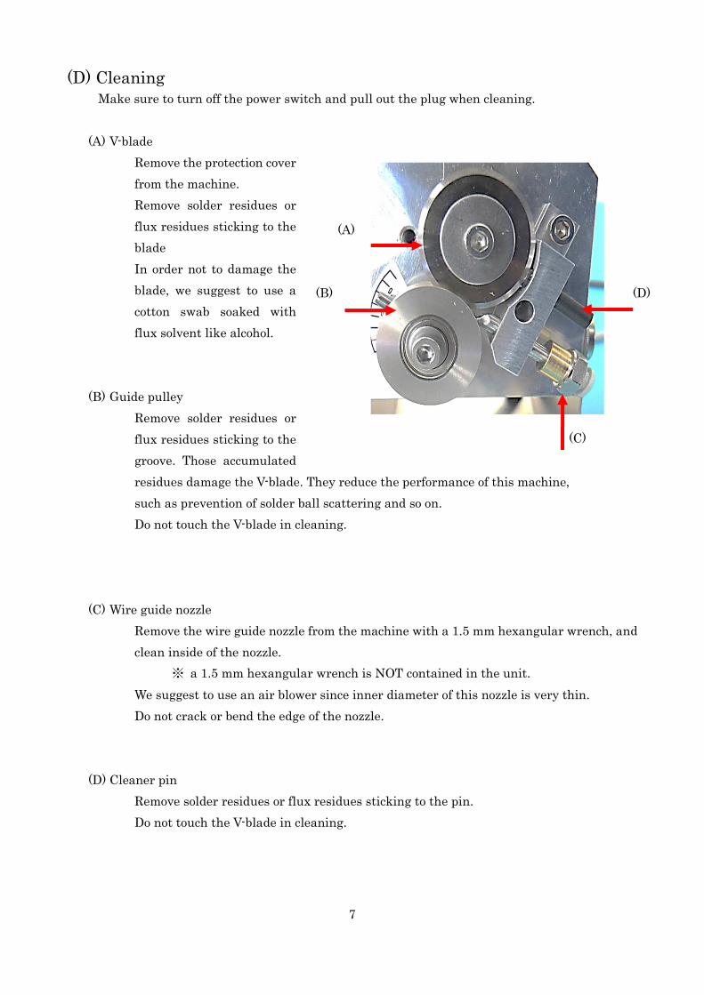
(D) Cleaning Make sure to turn off the power switch and pull out the plug when cleaning.
(A) V-blade
Remove the protection cover
from the machine.
Remove solder residues or
flux residues sticking to the
blade
In order not to damage the
blade, we suggest to use a
cotton swab soaked with
flux solvent like alcohol.
(B) Guide pulley
Remove solder residues or
flux residues sticking to the
groove. Those accumulated
residues damage the V-blade. They reduce the performance of this machine,
such as prevention of solder ball scattering and so on.
Do not touch the V-blade in cleaning.
(C) Wire guide nozzle
Remove the wire guide nozzle from the machine with a 1.5 mm hexangular wrench, and
clean inside of the nozzle.
※ a 1.5 mm hexangular wrench is NOT contained in the unit.
We suggest to use an air blower since inner diameter of this nozzle is very thin.
Do not crack or bend the edge of the nozzle.
(D) Cleaner pin
Remove solder residues or flux residues sticking to the pin.
Do not touch the V-blade in cleaning.
(D)
(A)
(C)
(B)

8
5. Specifications
Input voltage 100 VAC (BON-8103) / 220 VAC (BON-8203)
Frequency 50 Hz 60 Hz
Feeding amount 37 mm/sec. 44 mm/sec.
Feeding method Footswitch
Applicable solder diameter DIA. 0.3 ~ DIA. 0.8 mm
Dimension 70W x 104D x 160H mm
Weight 1175 g (body + power cable + footswitch)
Power consumption approx.. 6.5 W
Power cable
L= 1.90 m 3pin plug cable
L= 1.85 m BS1363 3pin plug cable
( a fuse is built-in)
Case material Steel : t = 1.0
6. Trouble shooting
How to set a solder wire Refer to page 5.
How to adjust solder diameter Refer to page 4.
How to adjust depth of V-groove Refer to page 6.
V-blade or guide pulley is getting
dirty. Refer to page 7.
Solder wire unable to feed.
1) Plug the power cable into the outlet firmly.
2) Check the solder wire diameter again and use
an appropriate solder wire.
V-blade or guide pulley is touching
with other parts. Contact us for repair.
Footswitch or motor is out of order. Contact us for repair.
Solder balls are getting increased.
1) Check the depth of V-groove and adjust it
accordingly. Refer to page 6.
2) Check the solder wire diameter again and use
an appropriate solder wire.
Solder balls are still increasing after
adjustments.
It is expectable of deterioration of V-blade or
guide pulley. Contact us for repair.
9
7. Guarantee and After sales service
(A) Guarantee We will ship our products after severe factory tests and inspections.
However, if you find any malfunctions or defects due to problem in workmanship or
transportation, please contact your dealer or us.
The guarantee period of your machine is in one year after purchased, except for replacement
parts.
(B) After sales service If the machine has trouble, please read this guide manual once again.
If the trouble is still not resolved, please contact your dealer or our service department.

JAPAN BONKOTE CO., LTD.JAPAN BONKOTE CO., LTD.JAPAN BONKOTE CO., LTD.JAPAN BONKOTE CO., LTD. 600-14 Kasahara-cho, Mito-shi, Ibaraki 310-0852 JAPAN TEL: +81 29-241-2725 FAX: +81 29-241-2726 URL: http://bonkote.co.jp E-mail: [email protected]