APPLICA TION NO TE - Skyworks Solutions are used to explain how to measure the PSRR of a Class D...
7
1 Skyworks Solutions, Inc. • Phone [781] 376-3000 • Fax [781] 376-3100 • [email protected] • www.skyworksinc.com 202382A • Skyworks Proprietary Information • Products and Product Information are Subject to Change Without Notice. • September 24, 2012 APPLICATION NOTE PSRR and Measurement of PSRR in Class-D Audio Amplifiers and LDOs Introduction This application note explains the importance of PSRR and shows how to calculate and measure it. Two examples using the AAT5101 Class D audio amplifier and the AAT2868 CABC Compatible 4 Channel Backlight Driver with Dual LDO Regulators are used to explain how to measure the PSRR of a Class D audio amplifier and a low dropout regulator (LDO). Additionally, a non-inverting amplifier adder circuit used in PSRR measurement is introduced at the end of this note. What is PSRR? Power Supply Rejection Ratio (PSRR) is the ratio of the output ripple voltage to the power supply ripple voltage; PSRR indicates how well a circuit rejects ripple coming from the power supply input at various frequencies. PSRR is an impor- tant parameter of amplifier and LDO performance in many applications, especially RF and wireless application. The Importance of PSRR In a typical portable RF application, the RF amplifier is turned on/off at a rate of 217Hz. At each of these events, a high current (typically, up to 1.7A) is drawn from the power supply, creating a sudden voltage drop (about 200mV) through the battery's equivalent series resistance (ESR)as shown in Figure 1. The battery also provides power to other devices such as an audio amplifier. The supply ripple caused by the RF amplifier will be injected into the audio ampli- fier, which then will appear at the same frequency as a voltage ripple in the audio amplifier output. Since 217Hz is within the audio bandwidth (20Hz to 20kHz) the ripple can be heard by the human ear as is observed as a fixed-fre- quency noise. The level of this noise depends on the PSRR performance of the audio amplifier. With excellent PSRR, the 217Hz noise will be rejected well and not disturb the audio performance. LDO RF Amplifier Audio Amplifier ESR I RF V BAT Audio In Figure 1: RF Subsystem Diagram.
-
Upload
truongliem -
Category
Documents
-
view
218 -
download
2
Transcript of APPLICA TION NO TE - Skyworks Solutions are used to explain how to measure the PSRR of a Class D...

1Skyworks Solutions, Inc. • Phone [781] 376-3000 • Fax [781] 376-3100 • [email protected] • www.skyworksinc.com
202382A • Skyworks Proprietary Information • Products and Product Information are Subject to Change Without Notice. • September 24, 2012
APPLICATION NOTE
PSRR and Measurement of PSRR in Class-D Audio Amplifiers and LDOs
IntroductionThis application note explains the importance of PSRR and shows how to calculate and measure it. Two examples using the AAT5101 Class D audio amplifier and the AAT2868 CABC Compatible 4 Channel Backlight Driver with Dual LDO Regulators are used to explain how to measure the PSRR of a Class D audio amplifier and a low dropout regulator (LDO). Additionally, a non-inverting amplifier adder circuit used in PSRR measurement is introduced at the end of this note.
What is PSRR?Power Supply Rejection Ratio (PSRR) is the ratio of the output ripple voltage to the power supply ripple voltage; PSRR indicates how well a circuit rejects ripple coming from the power supply input at various frequencies. PSRR is an impor-tant parameter of amplifier and LDO performance in many applications, especially RF and wireless application.
The Importance of PSRRIn a typical portable RF application, the RF amplifier is turned on/off at a rate of 217Hz. At each of these events, a high current (typically, up to 1.7A) is drawn from the power supply, creating a sudden voltage drop (about 200mV) through the battery's equivalent series resistance (ESR)as shown in Figure 1. The battery also provides power to other devices such as an audio amplifier. The supply ripple caused by the RF amplifier will be injected into the audio ampli-fier, which then will appear at the same frequency as a voltage ripple in the audio amplifier output. Since 217Hz is within the audio bandwidth (20Hz to 20kHz) the ripple can be heard by the human ear as is observed as a fixed-fre-quency noise. The level of this noise depends on the PSRR performance of the audio amplifier. With excellent PSRR, the 217Hz noise will be rejected well and not disturb the audio performance.
LDORF
Amplifier
Audio Amplifier
ESR
IRF
VBAT
Audio In
Figure 1: RF Subsystem Diagram.
APPLICATION NOTE
PSRR and Measurement of PSRR in Class-D Audio Amplifiers and LDOs
2Skyworks Solutions, Inc. • Phone [781] 376-3000 • Fax [781] 376-3100 • [email protected] • www.skyworksinc.com
202382A • Skyworks Proprietary Information • Products and Product Information are Subject to Change Without Notice. • September 24, 2012
Calculating PSRRThe PSRR of the audio amplifier can be calculated using Equation 1:
Eq. 1: PSRR = 20 · logVRIPPLE(OUT)
VRIPPLE(IN)
For example, if there is 200mV peak-to-peak ripple in the power supply input and the same frequency voltage ripple in the amplifier output at 200μV peak-to-peak.
The PSRR of the LDO can then be calculated using Equation 2:
Eq. 2: PSRR = 20 · log = -60dB200 · 10-6
200 · 10-3
However, in an LDO, the PSRR is always expressed as a positive value.
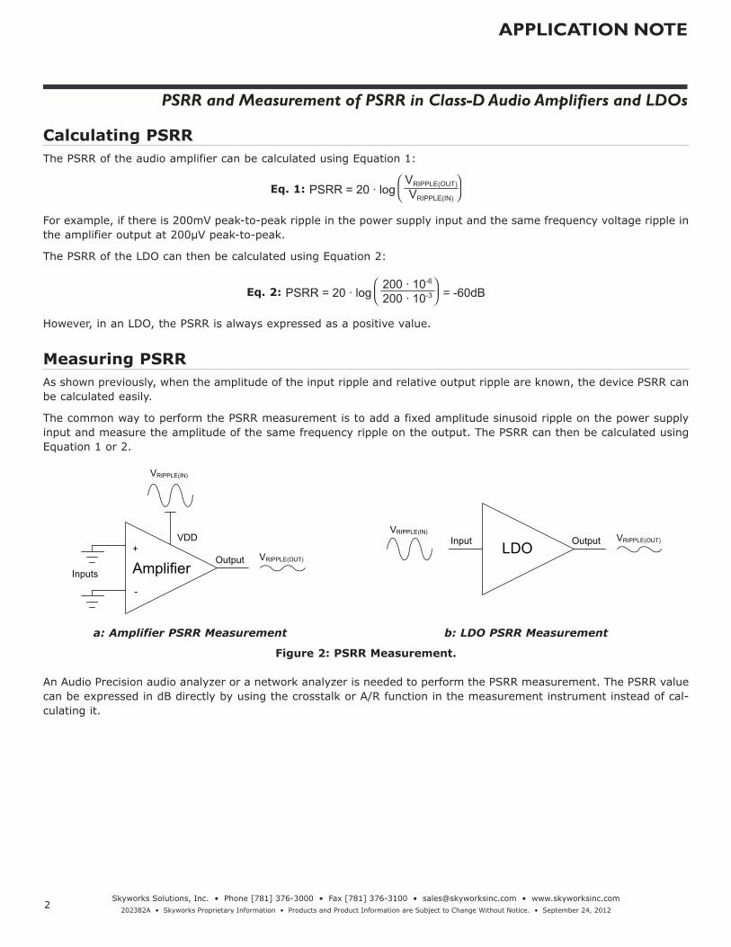
Measuring PSRRAs shown previously, when the amplitude of the input ripple and relative output ripple are known, the device PSRR can be calculated easily.
The common way to perform the PSRR measurement is to add a fixed amplitude sinusoid ripple on the power supply input and measure the amplitude of the same frequency ripple on the output. The PSRR can then be calculated using Equation 1 or 2.
Inputs
-
+Output
VRIPPLE(IN)
VRIPPLE(OUT)
VDD
Amplifier
VRIPPLE(IN)
Output VRIPPLE(OUT)Input LDO
a: Amplifier PSRR Measurement b: LDO PSRR Measurement
Figure 2: PSRR Measurement.
An Audio Precision audio analyzer or a network analyzer is needed to perform the PSRR measurement. The PSRR value can be expressed in dB directly by using the crosstalk or A/R function in the measurement instrument instead of cal-culating it.

APPLICATION NOTE
PSRR and Measurement of PSRR in Class-D Audio Amplifiers and LDOs
3Skyworks Solutions, Inc. • Phone [781] 376-3000 • Fax [781] 376-3100 • [email protected] • www.skyworksinc.com
202382A • Skyworks Proprietary Information • Products and Product Information are Subject to Change Without Notice. • September 24, 2012
PSRR Measurement of Class D Audio AmplifierFigure 3 shows the PSRR measurement set-up for the AAT5101 Class D audio amplifier. In this case, the DC power sup-ply, non-inverting amplifier adder, an 8Ω load, 30kHz low pass filter, and Audio Precision analyzer AP-SYS2722 are needed.
INP
INN
VDD
OUTP
OUTN
AAT5101
GND
+
-
LPF
Load
Adder
VS+
VS-
+
-
INB
INAAudioPrecision
(SYS2722) AudioPrecision
(SYS2722)
OUT
DC SupplyDC InputVoltage
Sine Ripple
Figure 3: AAT5101 PSRR Measurement Set-up.
The inputs of the AAT5101 should be AC grounded as shown. A 200mV peak to peak sinusoid ripple generated from the Audio Precision analyzer output is added onto the power supply input through the non-inverting amplifier adder. The output ripple can be measured by the Audio Precision (AP) analyzer through a 30kHz low pass filter (LPF). Connect the power supply input (VDD) to the AP’s channel A and connect the output of the low pass filter to the AP’s channel B. Choose the crosstalk function and scan frequency from 20Hz to 20kHz, then a resulting curve of PSRR over the audio bandwidth will be measured as shown in Figure 4. Adjust the power supply DC value to the intended system operating range.
Figure 4 shows the AAT5101 PSRR measurement results for DC input values of VDD at 2.5V, 3.6V and 5V.
Figure 4: AAT5101 PSRR Result.

APPLICATION NOTE
PSRR and Measurement of PSRR in Class-D Audio Amplifiers and LDOs
4Skyworks Solutions, Inc. • Phone [781] 376-3000 • Fax [781] 376-3100 • [email protected] • www.skyworksinc.com
202382A • Skyworks Proprietary Information • Products and Product Information are Subject to Change Without Notice. • September 24, 2012
PSRR Measurement of LDOFigure 5 shows the PSRR measurement set-up for the AAT2868 which contains two LDO regulators. In this example, the DC power supply, non-inverting amplifier adder, DC electronic load, and a network analyzer such as the Agilent 4395A are needed.
Adder
VS+
VS-
INR
INA
NetworkAnalyzer(4395A)
NetworkAnalyzer(4395A)
RFOUT
AAT2868
INLDO LDOA
GND
DC Supply
eLoad
DC Input Voltage
Sine Ripple
Figure 5: AAT2868 LDO Part PSRR Measurement Set-up.
A 200mV peak-to-peak sinusoid ripple waveform generated from network analyzer output is added onto the power supply input (INLDO) through the non-inverting amplifier adder. The output voltage can be measured by the network analyzer. Connect the LDO input to the network port INA and connect the LDO output to the network port INR. Chose the A/R function and a scan frequency from 100Hz to 100kHz. Adjust the power supply DC value to the intended sys-tem operating range.
Figure 6 shows the PSRR measurement result using the AAT2868 LDO for the condition: VIN = 3.6V, VRIPPLE = 200mVpp, ILOAD =10mA.
Figure 6: AAT2868 LDO PSRR Measurement Result.

APPLICATION NOTE
PSRR and Measurement of PSRR in Class-D Audio Amplifiers and LDOs
5Skyworks Solutions, Inc. • Phone [781] 376-3000 • Fax [781] 376-3100 • [email protected] • www.skyworksinc.com
202382A • Skyworks Proprietary Information • Products and Product Information are Subject to Change Without Notice. • September 24, 2012
Design and Application of the Non-inverting Amplifier AdderTo generate a DC power with a certain sinusoid ripple waveform added, a non-inverting amplifier adder is adopted. The output of the adder will be DC+AC as shown in Figure 7.
Adder DC Input Voltage
Ripple Peak Value
DC Input Voltage
Sine Ripple
Figure 7: Adder for PSRR Measurement.
Figures 8 and 9 show the schematic and board picture of the non-inverting amplifier adder used in the PSRR measure-ment.
C1
C30.1μF
R120Ω
R2
+12V
OUTV+
V-
U1A
470μF
C410μF
10μFC2
0.1μF
-12V
C5
OPADC Input Voltage
Ripple Peak Value
DC Input Voltage
Sine Ripple
0Ω
Figure 8: Schematic of the Non-inverting Amplifier Adder in PSRR Measurement.

APPLICATION NOTE
PSRR and Measurement of PSRR in Class-D Audio Amplifiers and LDOs
6Skyworks Solutions, Inc. • Phone [781] 376-3000 • Fax [781] 376-3100 • [email protected] • www.skyworksinc.com
202382A • Skyworks Proprietary Information • Products and Product Information are Subject to Change Without Notice. • September 24, 2012
Figure 9: Board Picture of the Non-inverting Amplifier Adder in PSRR Measurement.
Connect ±12V DC power to +12V and -12V on the board. Connect the power supply input voltage of the test device to VDD. Connect the output of audio precision or network analyzer to In to supply the desire sinusoid ripple. The DC+AC voltage of VDD + In signal will be generated at OUT.
Figure 10 shows the system connecting of the set-up described above.
Power supply provides ±12V to the adder board.
+5V DC power supply input.
Sine ripple fed into adder generated by Audio Precision or Network output.
Yellow trace is the DC+AC output of the adder.
Figure 10: Real Connect of the Non-inverting Amplifier Adder Board.
The yellow curve on the scope is the sinusoid ripple waveform before the non-inverting amplifier adder and the blue curve is the DC+AC signal of the Adder output.

APPLICATION NOTE
PSRR and Measurement of PSRR in Class-D Audio Amplifiers and LDOs
7Skyworks Solutions, Inc. • Phone [781] 376-3000 • Fax [781] 376-3100 • [email protected] • www.skyworksinc.com
202382A • Skyworks Proprietary Information • Products and Product Information are Subject to Change Without Notice. • September 24, 2012
Copyright © 2012 Skyworks Solutions, Inc. All Rights Reserved.
Information in this document is provided in connection with Skyworks Solutions, Inc. (“Skyworks”) products or services. These materials, including the information contained herein, are provided by Skyworks as a service to its customers and may be used for informational purposes only by the customer. Skyworks assumes no responsibility for errors or omissions in these materials or the information contained herein. Sky-works may change its documentation, products, services, specifications or product descriptions at any time, without notice. Skyworks makes no commitment to update the materials or information and shall have no responsibility whatsoever for conflicts, incompatibilities, or other difficulties arising from any future changes.
No license, whether express, implied, by estoppel or otherwise, is granted to any intellectual property rights by this document. Skyworks assumes no liability for any materials, products or information provided here-under, including the sale, distribution, reproduction or use of Skyworks products, information or materials, except as may be provided in Skyworks Terms and Conditions of Sale.
THE MATERIALS, PRODUCTS AND INFORMATION ARE PROVIDED “AS IS” WITHOUT WARRANTY OF ANY KIND, WHETHER EXPRESS, IMPLIED, STATUTORY, OR OTHERWISE, INCLUDING FITNESS FOR A PARTICULAR PURPOSE OR USE, MERCHANTABILITY, PERFORMANCE, QUALITY OR NON-INFRINGEMENT OF ANY INTELLECTUAL PROPERTY RIGHT; ALL SUCH WARRANTIES ARE HEREBY EXPRESSLY DISCLAIMED. SKYWORKS DOES NOT WARRANT THE ACCURACY OR COMPLETENESS OF THE INFORMATION, TEXT, GRAPHICS OR OTHER ITEMS CONTAINED WITHIN THESE MATERIALS. SKYWORKS SHALL NOT BE LIABLE FOR ANY DAMAGES, IN-CLUDING BUT NOT LIMITED TO ANY SPECIAL, INDIRECT, INCIDENTAL, STATUTORY, OR CONSEQUENTIAL DAMAGES, INCLUDING WITHOUT LIMITATION, LOST REVENUES OR LOST PROFITS THAT MAY RESULT FROM THE USE OF THE MATERIALS OR INFORMATION, WHETHER OR NOT THE RECIPIENT OF MATERIALS HAS BEEN ADVISED OF THE POSSIBILITY OF SUCH DAMAGE.
Skyworks products are not intended for use in medical, lifesaving or life-sustaining applications, or other equipment in which the failure of the Skyworks products could lead to personal injury, death, physical or en-vironmental damage. Skyworks customers using or selling Skyworks products for use in such applications do so at their own risk and agree to fully indemnify Skyworks for any damages resulting from such improper use or sale.
Customers are responsible for their products and applications using Skyworks products, which may deviate from published specifications as a result of design defects, errors, or operation of products outside of pub-lished parameters or design specifications. Customers should include design and operating safeguards to minimize these and other risks. Skyworks assumes no liability for applications assistance, customer product design, or damage to any equipment resulting from the use of Skyworks products outside of stated published specifications or parameters.
Skyworks, the Skyworks symbol, and “Breakthrough Simplicity” are trademarks or registered trademarks of Skyworks Solutions, Inc., in the United States and other countries. Third-party brands and names are for identification purposes only, and are the property of their respective owners. Additional information, including relevant terms and conditions, posted at www.skyworksinc.com, are incorporated by reference.
ConclusionThe PSRR measurement indicates how well a circuit rejects ripple or noise from the power supply input. When making a PSRR measurement, the biggest challenge is that the output ripple amplitude is very small. This makes it difficult to measure accurately using common equipment such as an oscilloscope or multi-meter. An Audio Precision analyzer (e.g. AP-SYS2722) or a network analyzer (e.g. Agilent 4395A) is necessary to do the measurement correctly.
Table 1 shows the required equipment and calculations for the Class D audio amplifier and the LDO PSRR measurement.
PSRR Calculation Measurement Equipment
Class D Audio Amplifier PSRR = 20 · logVRIPPLE(OUT)
VRIPPLE(IN) Audio Precision (e.g. AP-SYS2722), Adder
LDO PSRR = 20 · logVRIPPLE(IN)
VRIPPLE(OUT) Network Analyzer (e.g. Agilent-4395A), Adder
Table 1: PSRR Calculation Equation and Measurement Equipment.


![APPLICATION NOTE SKY77344-21 Power Amplifier … Notes/Skyworks...APPLICATION NOTE SKY77344 POWER AMPLIFIER MODULE – EVALUATION INFORMATION Skyworks Solutions, Inc. • Phone [781]](https://static.fdocuments.us/doc/165x107/5aeb162d7f8b9a90318c8547/application-note-sky77344-21-power-amplifier-notesskyworksapplication-note.jpg)