Appliance Quick Start Guide v7 - Load Balancing...Appliance Quick ...
56
Appliance Quick Start Guide v7.6 rev. 1.0.7 Copyright © 2002 – 2015 Loadbalancer.org, Inc.
-
Upload
truongdiep -
Category
Documents
-
view
222 -
download
0
Transcript of Appliance Quick Start Guide v7 - Load Balancing...Appliance Quick ...

Appliance Quick Start Guide
v7.6
rev. 1.0.7
Copyright © 2002 – 2015 Loadbalancer.org, Inc.
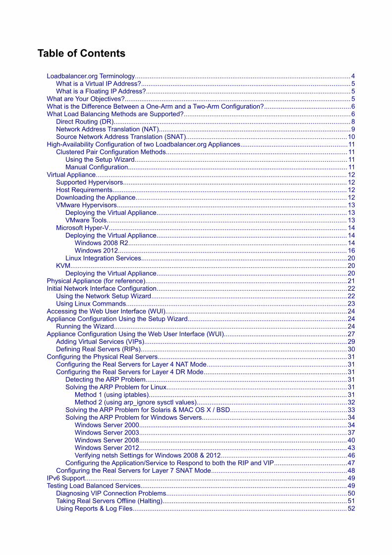
Table of Contents
Loadbalancer.org Terminology..................................................................................................................... 4What is a Virtual IP Address?................................................................................................................. 5What is a Floating IP Address?...............................................................................................................5
What are Your Objectives?.......................................................................................................................... 5What is the Difference Between a One-Arm and a Two-Arm Configuration?...............................................6What Load Balancing Methods are Supported?..........................................................................................6
Direct Routing (DR)................................................................................................................................ 8Network Address Translation (NAT)........................................................................................................9Source Network Address Translation (SNAT).......................................................................................10
High-Availability Configuration of two Loadbalancer.org Appliances..........................................................11Clustered Pair Configuration Methods..................................................................................................11
Using the Setup Wizard................................................................................................................... 11Manual Configuration....................................................................................................................... 11
Virtual Appliance........................................................................................................................................ 12Supported Hypervisors......................................................................................................................... 12Host Requirements............................................................................................................................... 12Downloading the Appliance.................................................................................................................. 12VMware Hypervisors............................................................................................................................. 13
Deploying the Virtual Appliance.......................................................................................................13VMware Tools.................................................................................................................................. 13
Microsoft Hyper-V................................................................................................................................. 14Deploying the Virtual Appliance.......................................................................................................14
Windows 2008 R2...................................................................................................................... 14Windows 2012............................................................................................................................ 16
Linux Integration Services...............................................................................................................20KVM...................................................................................................................................................... 20
Deploying the Virtual Appliance.......................................................................................................20Physical Appliance (for reference).............................................................................................................21Initial Network Interface Configuration.......................................................................................................22
Using the Network Setup Wizard..........................................................................................................22Using Linux Commands........................................................................................................................ 23
Accessing the Web User Interface (WUI)..................................................................................................24Appliance Configuration Using the Setup Wizard......................................................................................24
Running the Wizard.............................................................................................................................. 24Appliance Configuration Using the Web User Interface (WUI)...................................................................27
Adding Virtual Services (VIPs)..............................................................................................................29Defining Real Servers (RIPs)................................................................................................................30
Configuring the Physical Real Servers......................................................................................................31Configuring the Real Servers for Layer 4 NAT Mode............................................................................31Configuring the Real Servers for Layer 4 DR Mode..............................................................................31
Detecting the ARP Problem.............................................................................................................31Solving the ARP Problem for Linux..................................................................................................31
Method 1 (using iptables)...........................................................................................................31Method 2 (using arp_ignore sysctl values).................................................................................32
Solving the ARP Problem for Solaris & MAC OS X / BSD...............................................................33Solving the ARP Problem for Windows Servers...............................................................................34
Windows Server 2000................................................................................................................34Windows Server 2003................................................................................................................37Windows Server 2008................................................................................................................40Windows Server 2012................................................................................................................43Verifying netsh Settings for Windows 2008 & 2012....................................................................46
Configuring the Application/Service to Respond to both the RIP and VIP.......................................47Configuring the Real Servers for Layer 7 SNAT Mode..........................................................................48
IPv6 Support.............................................................................................................................................. 49Testing Load Balanced Services................................................................................................................49
Diagnosing VIP Connection Problems..................................................................................................50Taking Real Servers Offline (Halting)....................................................................................................51Using Reports & Log Files.................................................................................................................... 52

Testing High-Availability for a Loadbalancer.org HA-Pair......................................................................52Does Your Application Cluster Correctly Handle its Own State?................................................................53
Replication Solutions for Shared Data..................................................................................................53Solutions for Session Data................................................................................................................... 53Persistence (aka Affinity)...................................................................................................................... 53What do You do if Your Application is not Stateless?............................................................................54
Loadbalancer.org Persistence Options............................................................................................54Loadbalancer.org Technical Support..........................................................................................................54Appendix.................................................................................................................................................... 55
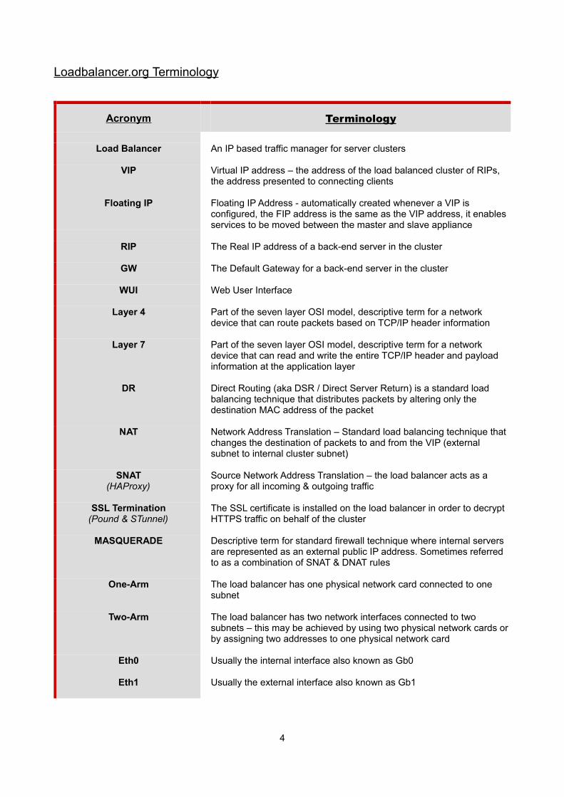
Loadbalancer.org Terminology
Acronym Terminology
Load Balancer An IP based traffic manager for server clusters
VIP Virtual IP address – the address of the load balanced cluster of RIPs, the address presented to connecting clients
Floating IP Floating IP Address - automatically created whenever a VIP is configured, the FIP address is the same as the VIP address, it enables services to be moved between the master and slave appliance
RIP The Real IP address of a back-end server in the cluster
GW The Default Gateway for a back-end server in the cluster
WUI Web User Interface
Layer 4 Part of the seven layer OSI model, descriptive term for a network device that can route packets based on TCP/IP header information
Layer 7 Part of the seven layer OSI model, descriptive term for a network device that can read and write the entire TCP/IP header and payload information at the application layer
DR Direct Routing (aka DSR / Direct Server Return) is a standard load balancing technique that distributes packets by altering only the destination MAC address of the packet
NAT Network Address Translation – Standard load balancing technique that changes the destination of packets to and from the VIP (external subnet to internal cluster subnet)
SNAT(HAProxy)
Source Network Address Translation – the load balancer acts as a proxy for all incoming & outgoing traffic
SSL Termination(Pound & STunnel)
The SSL certificate is installed on the load balancer in order to decrypt HTTPS traffic on behalf of the cluster
MASQUERADE Descriptive term for standard firewall technique where internal servers are represented as an external public IP address. Sometimes referred to as a combination of SNAT & DNAT rules
One-Arm The load balancer has one physical network card connected to one subnet
Two-Arm The load balancer has two network interfaces connected to two subnets – this may be achieved by using two physical network cards orby assigning two addresses to one physical network card
Eth0 Usually the internal interface also known as Gb0
Eth1 Usually the external interface also known as Gb1
4
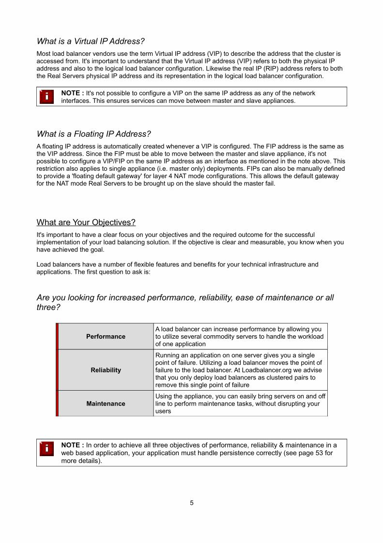
What is a Virtual IP Address?
Most load balancer vendors use the term Virtual IP address (VIP) to describe the address that the cluster is accessed from. It's important to understand that the Virtual IP address (VIP) refers to both the physical IP address and also to the logical load balancer configuration. Likewise the real IP (RIP) address refers to both the Real Servers physical IP address and its representation in the logical load balancer configuration.
NOTE : It's not possible to configure a VIP on the same IP address as any of the network interfaces. This ensures services can move between master and slave appliances.
What is a Floating IP Address?
A floating IP address is automatically created whenever a VIP is configured. The FIP address is the same as the VIP address. Since the FIP must be able to move between the master and slave appliance, it's not possible to configure a VIP/FIP on the same IP address as an interface as mentioned in the note above. Thisrestriction also applies to single appliance (i.e. master only) deployments. FIPs can also be manually definedto provide a 'floating default gateway' for layer 4 NAT mode configurations. This allows the default gateway for the NAT mode Real Servers to be brought up on the slave should the master fail.
What are Your Objectives?
It's important to have a clear focus on your objectives and the required outcome for the successful implementation of your load balancing solution. If the objective is clear and measurable, you know when you have achieved the goal.
Load balancers have a number of flexible features and benefits for your technical infrastructure and applications. The first question to ask is:
Are you looking for increased performance, reliability, ease of maintenance or all three?
PerformanceA load balancer can increase performance by allowing you to utilize several commodity servers to handle the workload of one application
Reliability
Running an application on one server gives you a single point of failure. Utilizing a load balancer moves the point of failure to the load balancer. At Loadbalancer.org we advise that you only deploy load balancers as clustered pairs to remove this single point of failure
MaintenanceUsing the appliance, you can easily bring servers on and offline to perform maintenance tasks, without disrupting your users
NOTE : In order to achieve all three objectives of performance, reliability & maintenance in a web based application, your application must handle persistence correctly (see page 53 for more details).
5
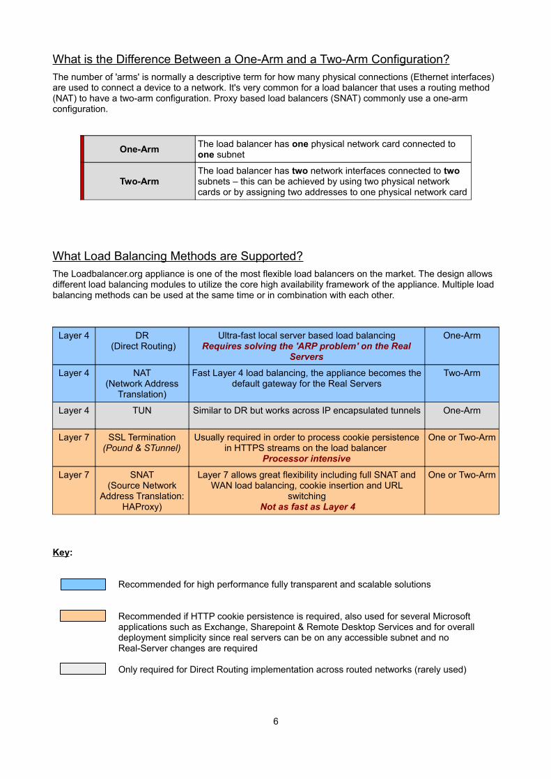
What is the Difference Between a One-Arm and a Two-Arm Configuration?
The number of 'arms' is normally a descriptive term for how many physical connections (Ethernet interfaces) are used to connect a device to a network. It's very common for a load balancer that uses a routing method (NAT) to have a two-arm configuration. Proxy based load balancers (SNAT) commonly use a one-arm configuration.
One-ArmThe load balancer has one physical network card connected to one subnet
Two-ArmThe load balancer has two network interfaces connected to two subnets – this can be achieved by using two physical network cards or by assigning two addresses to one physical network card
What Load Balancing Methods are Supported?
The Loadbalancer.org appliance is one of the most flexible load balancers on the market. The design allows different load balancing modules to utilize the core high availability framework of the appliance. Multiple load balancing methods can be used at the same time or in combination with each other.
Layer 4 DR (Direct Routing)
Ultra-fast local server based load balancingRequires solving the 'ARP problem' on the Real
Servers
One-Arm
Layer 4 NAT(Network Address
Translation)
Fast Layer 4 load balancing, the appliance becomes thedefault gateway for the Real Servers
Two-Arm
Layer 4 TUN Similar to DR but works across IP encapsulated tunnels One-Arm
Layer 7 SSL Termination(Pound & STunnel)
Usually required in order to process cookie persistencein HTTPS streams on the load balancer
Processor intensive
One or Two-Arm
Layer 7 SNAT(Source Network
Address Translation:HAProxy)
Layer 7 allows great flexibility including full SNAT andWAN load balancing, cookie insertion and URL
switching Not as fast as Layer 4
One or Two-Arm
Key:
Recommended for high performance fully transparent and scalable solutions
Recommended if HTTP cookie persistence is required, also used for several Microsoft applications such as Exchange, Sharepoint & Remote Desktop Services and for overall deployment simplicity since real servers can be on any accessible subnet and noReal-Server changes are required
Only required for Direct Routing implementation across routed networks (rarely used)
6
Loadbalancer.org Recommendation:
Where feasible, one-arm layer 4 Direct Routing (DR) mode is our recommended method because it's a very high performance solution with little change to your existing infrastructure.
NOTE : Sometimes it's not possible to use DR mode. The two most common reasons being: if the application cannot bind to the RIP & VIP at the same time; or if the host operating system cannot be modified to handle the ARP problem (see page 31-48 for more details).
A second option is layer 4 Network Address Translation (NAT) mode. This is a fairly high performance solution but it requires the implementation of a two-arm infrastructure with an internal and external subnet to carry out the translation (the same way a firewall works). Network engineers with experience of hardware load balancers will have often used this method.
The third option is layer 7 Source Network Address Translation (SNAT) mode using HAProxy. If your application requires that the load balancer handles cookie insertion, RDP cookies, Session Broker integrationor SSL termination then this option is appropriate. This can be deployed in one-arm or two-arm mode and does not require any changes to the application servers. HAProxy is a high-performance solution that operates as a full proxy, but due to this it cannot perform as fast as the layer 4 solutions.
NOTE : If your application doesn't maintain its own state information then you may need to usecookie insertion to maintain server persistence (affinity).
The following sections describe these configurations in more details.
IMPORTANT NOTE : If you are using Microsoft Windows Real Servers (i.e. back-end servers)make sure that Windows NLB (Network Load Balancing) is completely disabled to ensure that this does not interfere with the operation of the load balancer.
7
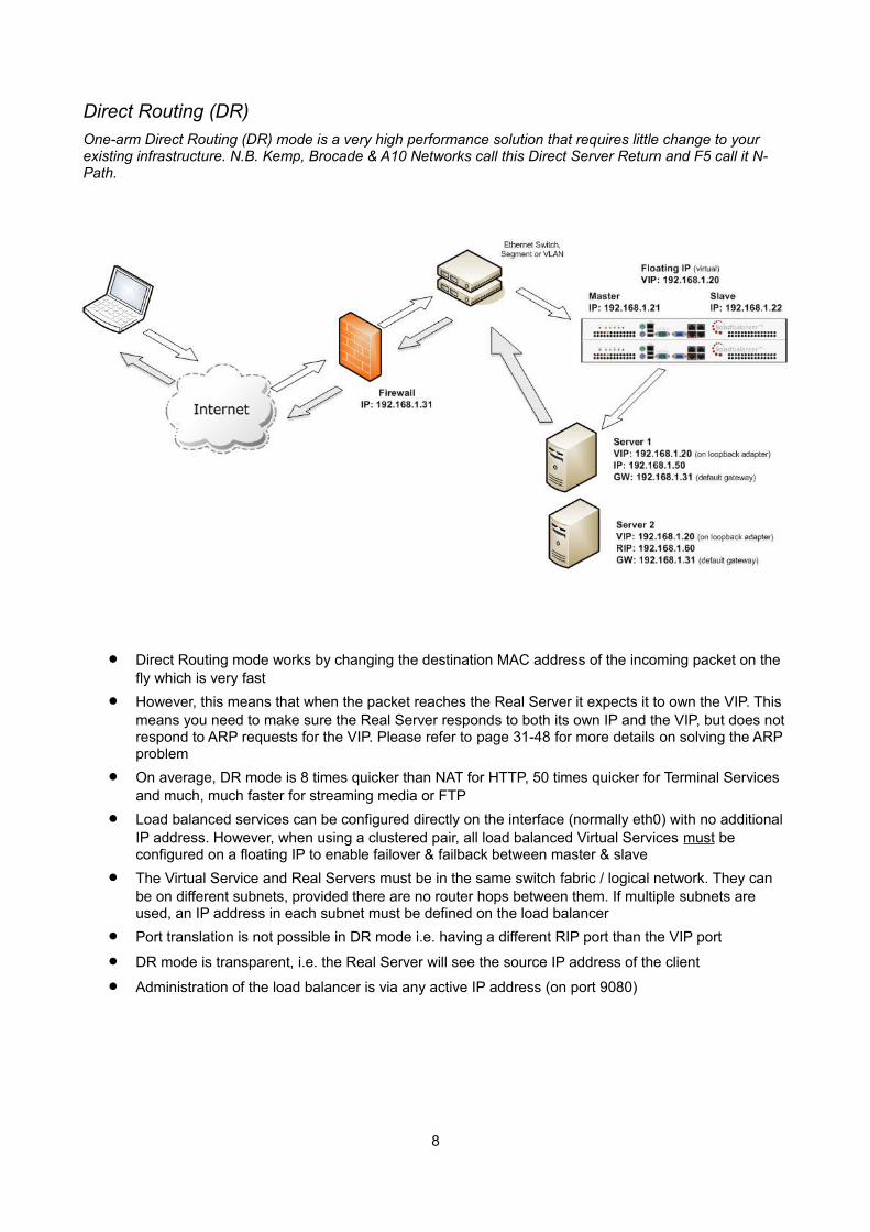
Direct Routing (DR)
One-arm Direct Routing (DR) mode is a very high performance solution that requires little change to your existing infrastructure. N.B. Kemp, Brocade & A10 Networks call this Direct Server Return and F5 call it N-Path.
Direct Routing mode works by changing the destination MAC address of the incoming packet on the fly which is very fast
However, this means that when the packet reaches the Real Server it expects it to own the VIP. This means you need to make sure the Real Server responds to both its own IP and the VIP, but does notrespond to ARP requests for the VIP. Please refer to page 31-48 for more details on solving the ARP problem
On average, DR mode is 8 times quicker than NAT for HTTP, 50 times quicker for Terminal Services and much, much faster for streaming media or FTP
Load balanced services can be configured directly on the interface (normally eth0) with no additional IP address. However, when using a clustered pair, all load balanced Virtual Services must be configured on a floating IP to enable failover & failback between master & slave
The Virtual Service and Real Servers must be in the same switch fabric / logical network. They can be on different subnets, provided there are no router hops between them. If multiple subnets are used, an IP address in each subnet must be defined on the load balancer
Port translation is not possible in DR mode i.e. having a different RIP port than the VIP port
DR mode is transparent, i.e. the Real Server will see the source IP address of the client
Administration of the load balancer is via any active IP address (on port 9080)
8
Network Address Translation (NAT)
Sometimes it's not possible to use DR mode. The two most common reasons being: if the application cannot bind to the RIP & VIP at the same time; or if the host operating system cannot be modified to handle the ARPproblem. The second choice is Network Address Translation (NAT) mode. This is also a high performance solution but it requires the implementation of a two arm infrastructure with an internal and external subnet to carry out the translation (the same way a firewall works).
In two-arm NAT mode the load balancer translates all requests from the external Virtual Service to the internal Real Servers
Normally eth0 is used for the internal network and eth1 is used for the external network although thisis not mandatory. If the Real Servers require Internet access, Autonat should be enabled using the WUI option: Cluster Configuration > Layer 4 – Advanced Configuration, select the external interface
When the wizard is used, Real Servers are automatically given access to the Internet through the load balancer (via Auto-NAT)
The Real Servers must have their default gateway configured to point at the load balancer. When master & slave units are used, a floating IP must be used to enable failover
Load balanced services can be configured directly on the interface (normally eth0) with no additional IP address. However, when using a clustered pair all load balanced Virtual Services must be configured on a floating IP to enable failover & failback between master & slave
Normally the Virtual Service and Real Servers should be located on different subnets within the same logical network (i.e. no router hops) and the load balancer should have an IP address in each subnet. N.B. It is possible to have Real and Virtual Services in the same subnet – please search for 'one-arm (Single Subnet) NAT Mode' in the administration manual. N.B. It is possible to have the IIS servers located on routed subnets, but this would require a customized routing configuration on the IIS servers and is not recommended
If you want Real Servers to be accessible on their own IP address for non-load balanced services, e.g. SMTP or RDP, you will need to setup individual SNAT and DNAT firewall script rules for each Real Server. Please search for 'Enabling Access to non Load-Balanced Services' in the administration manual for more details
NAT mode is transparent, i.e. the Real Server will see the source IP address of the client
Administration of the load balancer is via any active IP address (on port 9080)
Port translation is possible in NAT mode, i.e. VIP:80 → RIP8080 is allowed
9
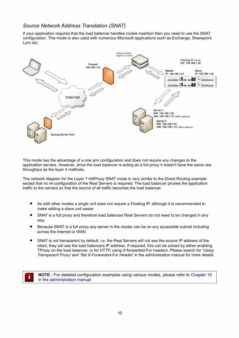
Source Network Address Translation (SNAT)
If your application requires that the load balancer handles cookie insertion then you need to use the SNAT configuration. This mode is also used with numerous Microsoft applications such as Exchange, Sharepoint, Lync etc.
This mode has the advantage of a one arm configuration and does not require any changes to the application servers. However, since the load balancer is acting as a full proxy it doesn't have the same raw throughput as the layer 4 methods.
The network diagram for the Layer 7 HAProxy SNAT mode is very similar to the Direct Routing example except that no re-configuration of the Real Servers is required. The load balancer proxies the application traffic to the servers so that the source of all traffic becomes the load balancer.
As with other modes a single unit does not require a Floating IP, although it is recommended to make adding a slave unit easier
SNAT is a full proxy and therefore load balanced Real Servers do not need to be changed in any way
Because SNAT is a full proxy any server in the cluster can be on any accessible subnet including across the Internet or WAN
SNAT is not transparent by default, i.e. the Real Servers will not see the source IP address of the client, they will see the load balancers IP address. If required, this can be solved by either enabling TProxy on the load balancer, or for HTTP, using X-forwarded-For headers. Please search for 'Using Transparent Proxy' and 'Set X-Forwarded-For Header' in the administration manual for more details.
NOTE : For detailed configuration examples using various modes, please refer to Chapter 10 in the administration manual
10
High-Availability Configuration of two Loadbalancer.org Appliances
Loadbalancer.org's recommended configuration is to use a clustered pair of load balancers to provide a highly available and resilient load balancing solution. In this configuration, the pair uses a heartbeat to determine the state of the other appliance. Should the active device (normally the master) suffer a failure, thepassive device (normally the slave) will take over any resources hosted on the shared floating IP addresses.
NOTE : Using a single load balancer introduces a single point of failure for your infrastructure so it is strongly recommended to use two appliances in a clustered pair.
Clustered Pair Configuration Methods
There are two ways to configure a clustered pair; either by using the wizard or configuring the units manually.
Using the Setup Wizard
The setup wizard enables an HA pair to be configured simply and quickly. This can be done either before or after load balanced services are defined. The IP address of both units must be configured and accessible before running the wizard. The IP address can be configured using one of the methods described on pages 22-23.
NOTE : For more details on using the setup wizard please refer to pages 24-27.
Manual Configuration
An HA pair can also be configured manually.
Points to note:
The role of the unit to be used as the slave must be set to 'slave' using the drop-down located under Local Configuration > Hostname & DNS in the WUI. Once updated, the hostname will be automatically set to 'lbslave'. This can also be changed to a custom value if required
The IP address of the slave must be defined on the master using the Slave Load Balancer Address field located under Cluster Configuration > Heartbeat Configuration in the WUI
The Synchronize Configuration with peer option located under Maintenance > Backup & Restore in the WUI should be used to force replication to the slave so both units are correctly synchronized
Once the IP address is set and synchronization has occurred, heartbeat must be restarted on the master unit as directed. This can be done using the WUI option: Maintenance > Restart Services andclicking Restart Heartbeat
NOTE : For more details please refer to the section Adding a Slave Unit after the Master has been Configured on page 158 in the administration manual
11
Virtual Appliance
The following sections detail the various VA's available, where they can be downloaded and how they are deployed.
Supported Hypervisors
Currently, the Virtual appliance is available for the following hypervisors:
• VMware (Player/Workstation/Server & ESX/ESXi)
• Microsoft Hyper-V
• KVM
Host Requirements
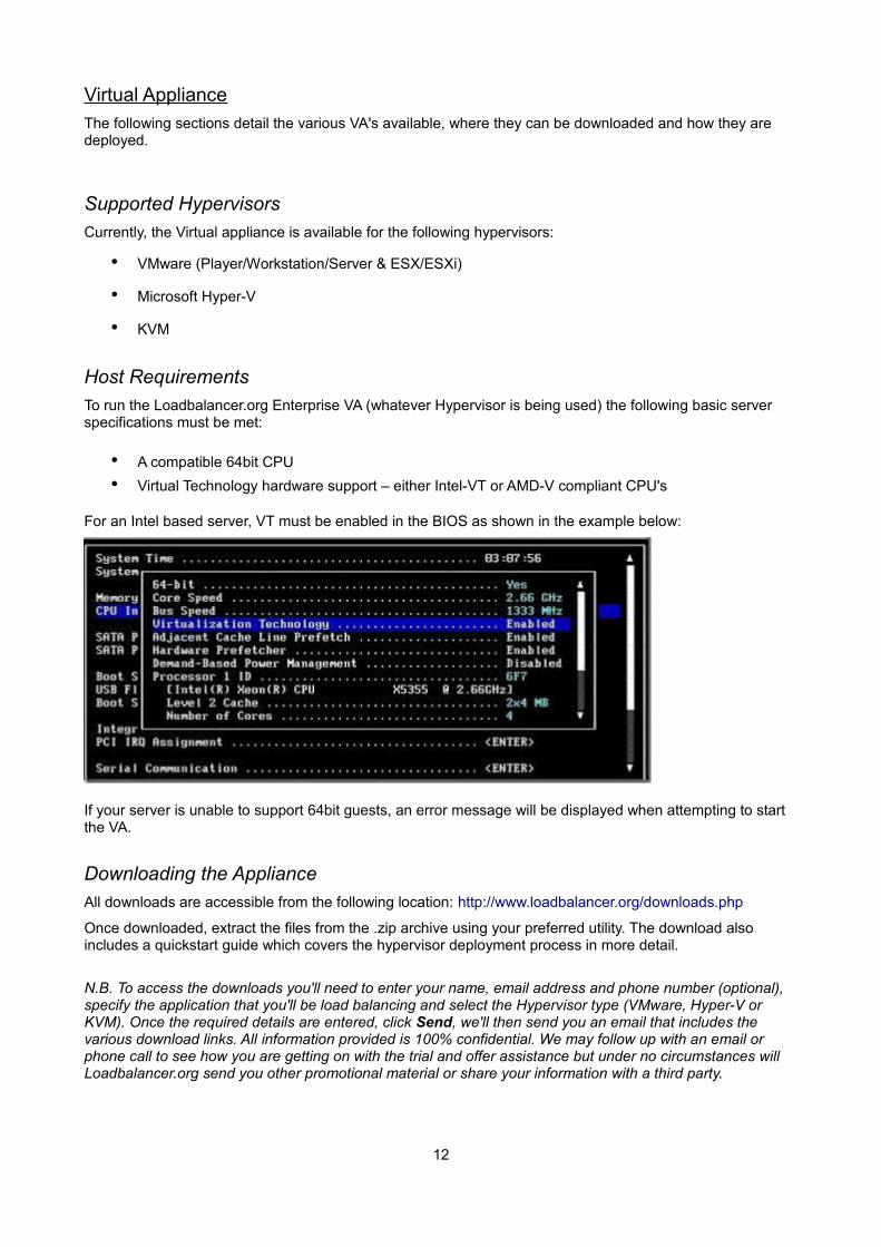
To run the Loadbalancer.org Enterprise VA (whatever Hypervisor is being used) the following basic server specifications must be met:
• A compatible 64bit CPU
• Virtual Technology hardware support – either Intel-VT or AMD-V compliant CPU's
For an Intel based server, VT must be enabled in the BIOS as shown in the example below:
If your server is unable to support 64bit guests, an error message will be displayed when attempting to start the VA.
Downloading the Appliance
All downloads are accessible from the following location: http://www.loadbalancer.org/downloads.php
Once downloaded, extract the files from the .zip archive using your preferred utility. The download also includes a quickstart guide which covers the hypervisor deployment process in more detail.
N.B. To access the downloads you'll need to enter your name, email address and phone number (optional), specify the application that you'll be load balancing and select the Hypervisor type (VMware, Hyper-V or KVM). Once the required details are entered, click Send, we'll then send you an email that includes the various download links. All information provided is 100% confidential. We may follow up with an email or phone call to see how you are getting on with the trial and offer assistance but under no circumstances will Loadbalancer.org send you other promotional material or share your information with a third party.
12
VMware Hypervisors
Three downloads are available as listed below:
1) ESX/ESXi v4.0 and later
• Download LBVMESXv7.zip (ovf v1.0, hardware v7)
2) VMware Player, Server & Workstation
• Download LBVMv7.zip (virtualHW.version = 4)
3) ESX/ESXi v3.5 and earlier
In this case you have two choices:
• Download LBVMESXv7_ovf0.9.zip (ovf v0.9, hardware v4)
or
• Download LBVMv7.zip and use the converter for your environment to convert to a compatible VA
NOTE : Due to Vmxnet3 driver compatibility limitations with earlier versions of ESX & ESXi only the LBVMESXv7.zip download uses the Vmxnet3 network drivers. The other downloads use E1000 drivers.
Deploying the Virtual Appliance
1. Download & extract the appropriate file (see previous section)
2. deploy the VA -
◦ For VMware Server use: Virtual Machine > Add VM to Inventory
◦ For vSphere use: File > Deploy ovf Template
◦ For Virtual Infrastructure use: File > Virtual Appliance > Import
3. Start the Virtual Appliance, allow a minute for booting
4. Now refer to pages 22-23 for details on setting up the network
VMware Tools
VMware tools are pre-installed on the appliance which enables basic console control functions such as power on/off etc. The installed version of the various kernel modules and drivers is controlled by Loadbalancer.org at build time to ensure that only stable, fully tested versions are deployed. If the tools are later upgraded, these drivers and modules may be over-written. Therefore we do NOT recommend a full tool re-installation. If you do want to update the basic tool functionality (i.e. without affecting the installed drivers and modules) please follow the steps listed in the following blog entry:
http://blog.loadbalancer.org/how-to-upgrade-vmware-tools-on-clusterload-esx-or-loadbalancerorg-va/
13
Microsoft Hyper-V
Two downloads are available as listed below depending on the version of Hyper-V:
1) Windows 2012 R2 & Later
• Download LBVMHYPER-V3v7.zip
2) Windows 2008 R2 & Windows 2012
• Download LBVMHYPER-Vv7.zip
Deploying the Virtual Appliance
The following two sections explain how the appliance is deployed under Windows 2008 and Windows 2012.
Windows 2008 R2
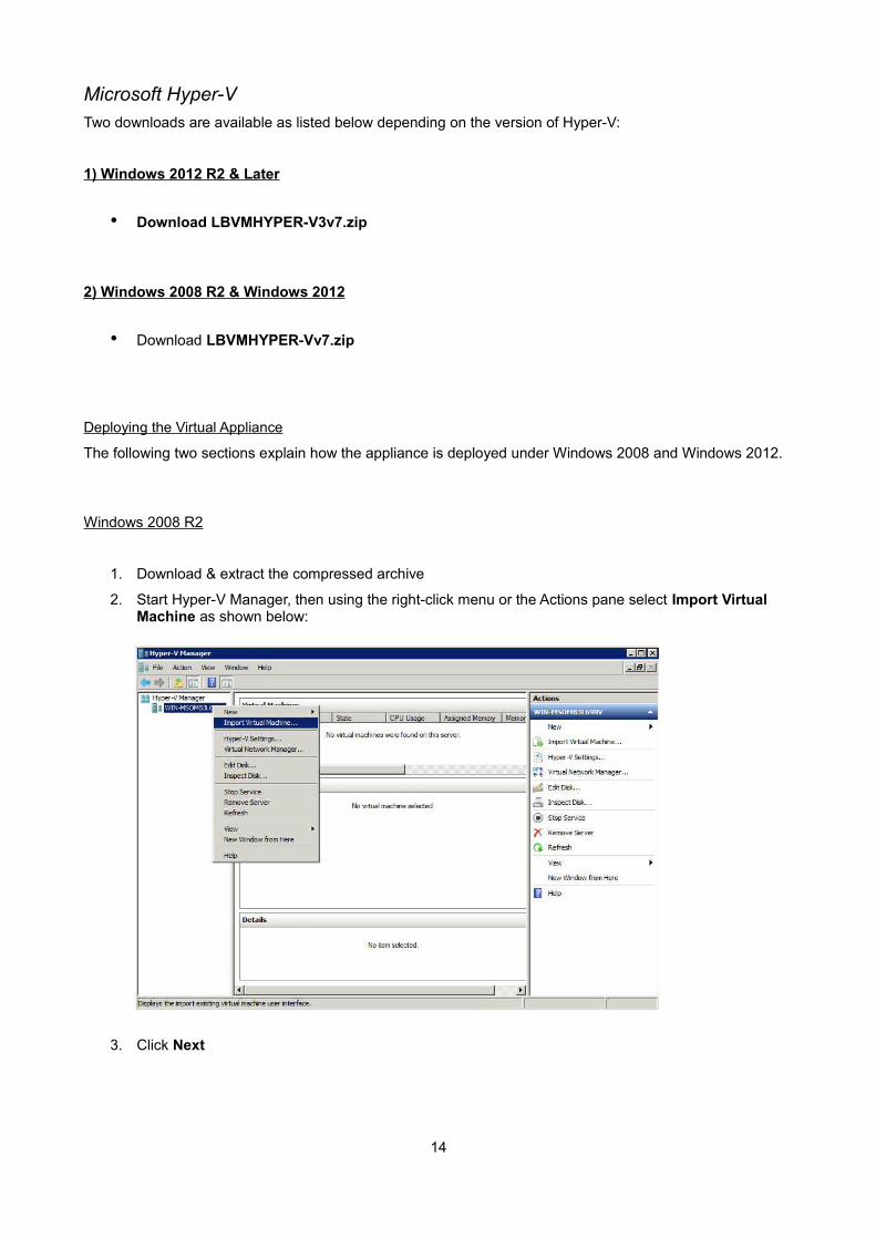
1. Download & extract the compressed archive
2. Start Hyper-V Manager, then using the right-click menu or the Actions pane select Import Virtual Machine as shown below:
3. Click Next
14
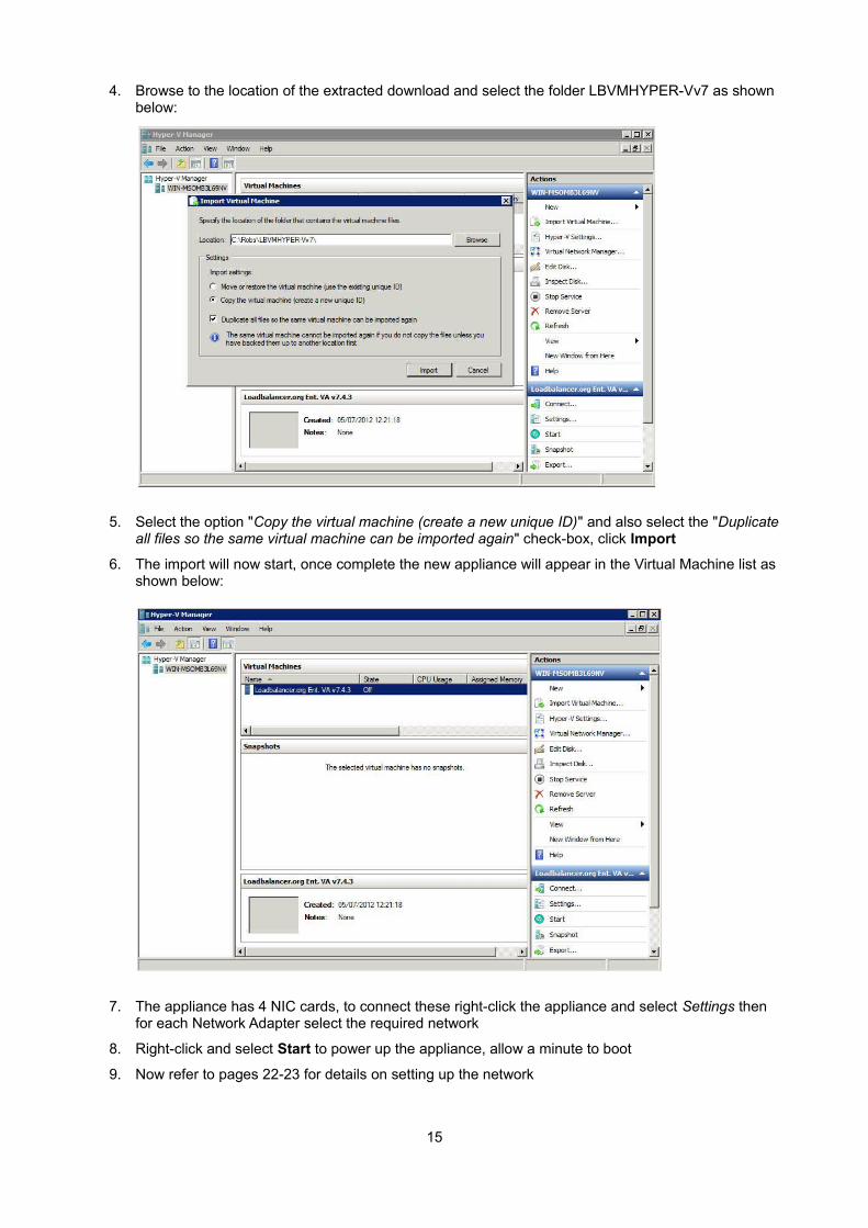
4. Browse to the location of the extracted download and select the folder LBVMHYPER-Vv7 as shown below:
5. Select the option "Copy the virtual machine (create a new unique ID)" and also select the "Duplicate all files so the same virtual machine can be imported again" check-box, click Import
6. The import will now start, once complete the new appliance will appear in the Virtual Machine list as shown below:
7. The appliance has 4 NIC cards, to connect these right-click the appliance and select Settings then for each Network Adapter select the required network
8. Right-click and select Start to power up the appliance, allow a minute to boot
9. Now refer to pages 22-23 for details on setting up the network
15
If you're deploying a clustered pair, you'll first need to do one of the following steps before importing the second virtual machine. If this is not done, the second virtual machine cannot be deployed because the disk from the first import already exists, and there will therefore be a conflict:
• Shutdown the first VM and modify the name of the disk
or
• Change the default file location using the Hyper-V Settings option in the Actions pane
Once one of the above steps is done, repeat steps 2-9 above to create the second virtual machine.
Windows 2012
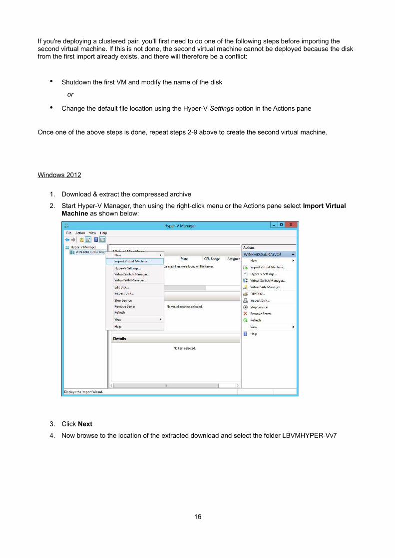
1. Download & extract the compressed archive
2. Start Hyper-V Manager, then using the right-click menu or the Actions pane select Import Virtual Machine as shown below:
3. Click Next
4. Now browse to the location of the extracted download and select the folder LBVMHYPER-Vv7
16
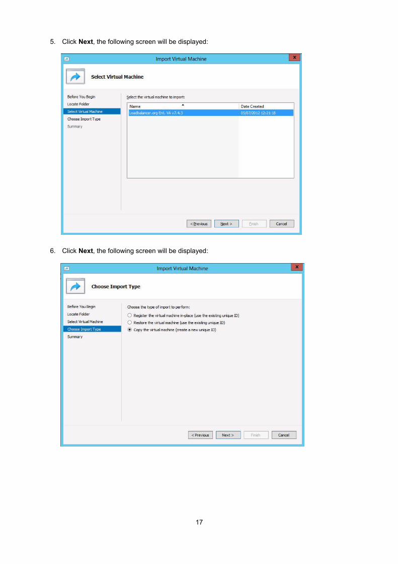
5. Click Next, the following screen will be displayed:
6. Click Next, the following screen will be displayed:
17
7. Make sure that 'Copy the virtual machine (create a new unique ID)' is selected and click Next, the following screen will be displayed:
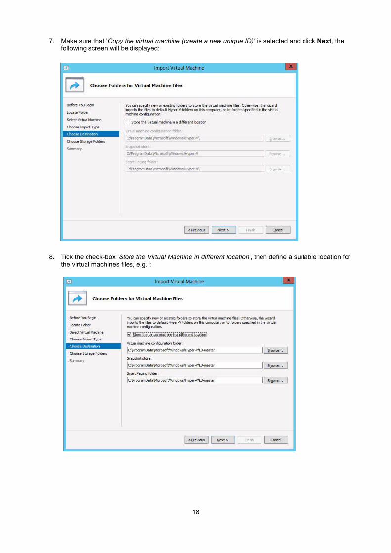
8. Tick the check-box 'Store the Virtual Machine in different location', then define a suitable location for the virtual machines files, e.g. :
18
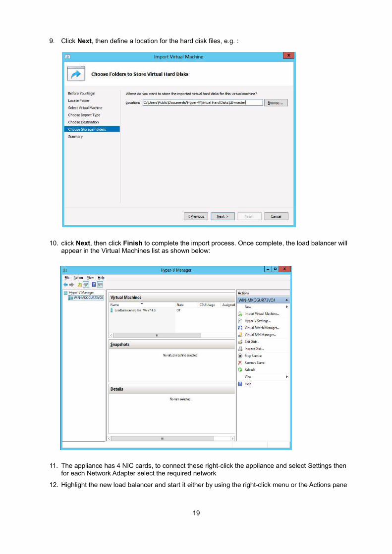
9. Click Next, then define a location for the hard disk files, e.g. :
10. click Next, then click Finish to complete the import process. Once complete, the load balancer will appear in the Virtual Machines list as shown below:
11. The appliance has 4 NIC cards, to connect these right-click the appliance and select Settings then for each Network Adapter select the required network
12. Highlight the new load balancer and start it either by using the right-click menu or the Actions pane
19
13. Now refer to pages 22-23 for details on setting up the network
If you're deploying a clustered pair, repeat steps 2-13 for the slave unit, making sure that a different folder location is selected in steps 8 & 9.
Linux Integration Services
From v7.6.3 of the appliance, Linux Integration Services are pre-installed by default. Manual installation is not required.
KVM
One download is available as listed below, this can be used for all versions of KVM.
1) All Version of KVM
• Download LBVMKVMv7.tar.bz2
Deploying the Virtual Appliance
The following steps should be followed on the KVM host:
1. Extract the archive to /var/lib/libvirt/images/
2. virsh define Loadbalancer*.xml
3. virsh start Loadbalancer*
N.B. Network cards are set to NAT by default so adjust as needed before powering on
N.B. Please refer to the XML file for additional configuration notes
20
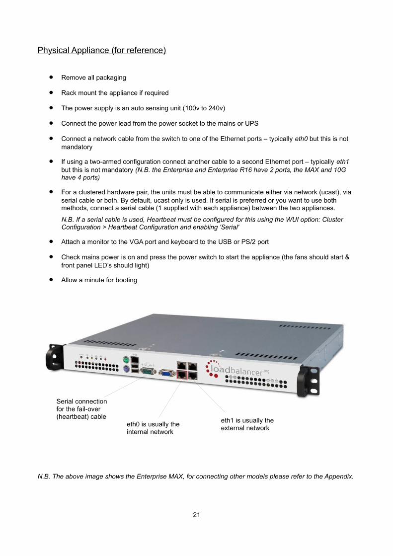
Physical Appliance (for reference)
Remove all packaging
Rack mount the appliance if required
The power supply is an auto sensing unit (100v to 240v)
Connect the power lead from the power socket to the mains or UPS
Connect a network cable from the switch to one of the Ethernet ports – typically eth0 but this is not mandatory
If using a two-armed configuration connect another cable to a second Ethernet port – typically eth1 but this is not mandatory (N.B. the Enterprise and Enterprise R16 have 2 ports, the MAX and 10G have 4 ports)
For a clustered hardware pair, the units must be able to communicate either via network (ucast), via serial cable or both. By default, ucast only is used. If serial is preferred or you want to use both methods, connect a serial cable (1 supplied with each appliance) between the two appliances.
N.B. If a serial cable is used, Heartbeat must be configured for this using the WUI option: Cluster Configuration > Heartbeat Configuration and enabling 'Serial'
Attach a monitor to the VGA port and keyboard to the USB or PS/2 port
Check mains power is on and press the power switch to start the appliance (the fans should start & front panel LED’s should light)
Allow a minute for booting
N.B. The above image shows the Enterprise MAX, for connecting other models please refer to the Appendix.
21
eth1 is usually the external network
eth0 is usually the internal network
Serial connection for the fail-over (heartbeat) cable
Initial Network Interface Configuration
By default the load balancer is pre-configured with the following IP address & subnet mask:
192.168.2.21 / 24 (192.168.2.21 / 255.255.255.0)
This default address can be changed at the console in two ways:
Using the built-in Network Setup Wizard
Using traditional Linux commands
NOTE : For the VA, four NICs are included but only eth0 is connected by default at power on. Ifthe other NICs are required, these should be connected using the network configuration screen within the Hypervisor.
Using the Network Setup Wizard
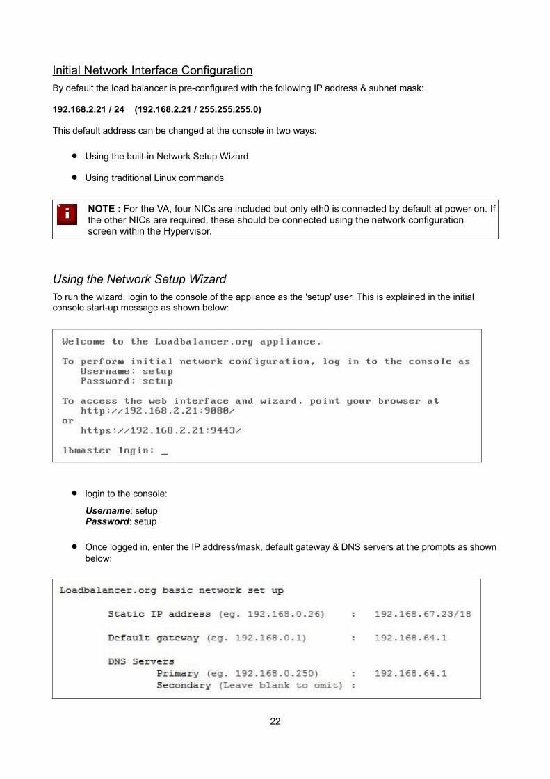
To run the wizard, login to the console of the appliance as the 'setup' user. This is explained in the initial console start-up message as shown below:
login to the console:
Username: setupPassword: setup
Once logged in, enter the IP address/mask, default gateway & DNS servers at the prompts as shownbelow:
22
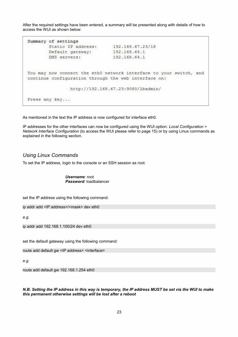
After the required settings have been entered, a summary will be presented along with details of how to access the WUI as shown below:
As mentioned in the text the IP address is now configured for interface eth0.
IP addresses for the other interfaces can now be configured using the WUI option: Local Configuration > Network Interface Configuration (to access the WUI please refer to page 15) or by using Linux commands asexplained in the following section.
Using Linux Commands
To set the IP address, login to the console or an SSH session as root:
Username: rootPassword: loadbalancer
set the IP address using the following command:
ip addr add <IP address>/<mask> dev eth0
e.g.
ip addr add 192.168.1.100/24 dev eth0
set the default gateway using the following command:
route add default gw <IP address> <interface>
e.g.
route add default gw 192.168.1.254 eth0
N.B. Setting the IP address in this way is temporary, the IP address MUST be set via the WUI to make this permanent otherwise settings will be lost after a reboot
23
Accessing the Web User Interface (WUI)
Using a web browser, access the WUI using the following URL:
http://192.168.2.21:9080/lbadmin/
(replace 192.168.2.21 with your IP address if it's been changed)
N.B. If you prefer you can use the HTTPS administration address:
https://192.168.2.21:9443/lbadmin/
(replace 192.168.2.21 with your IP address if it's been changed)
Login to the WUI:
Username: loadbalancerPassword: loadbalancer
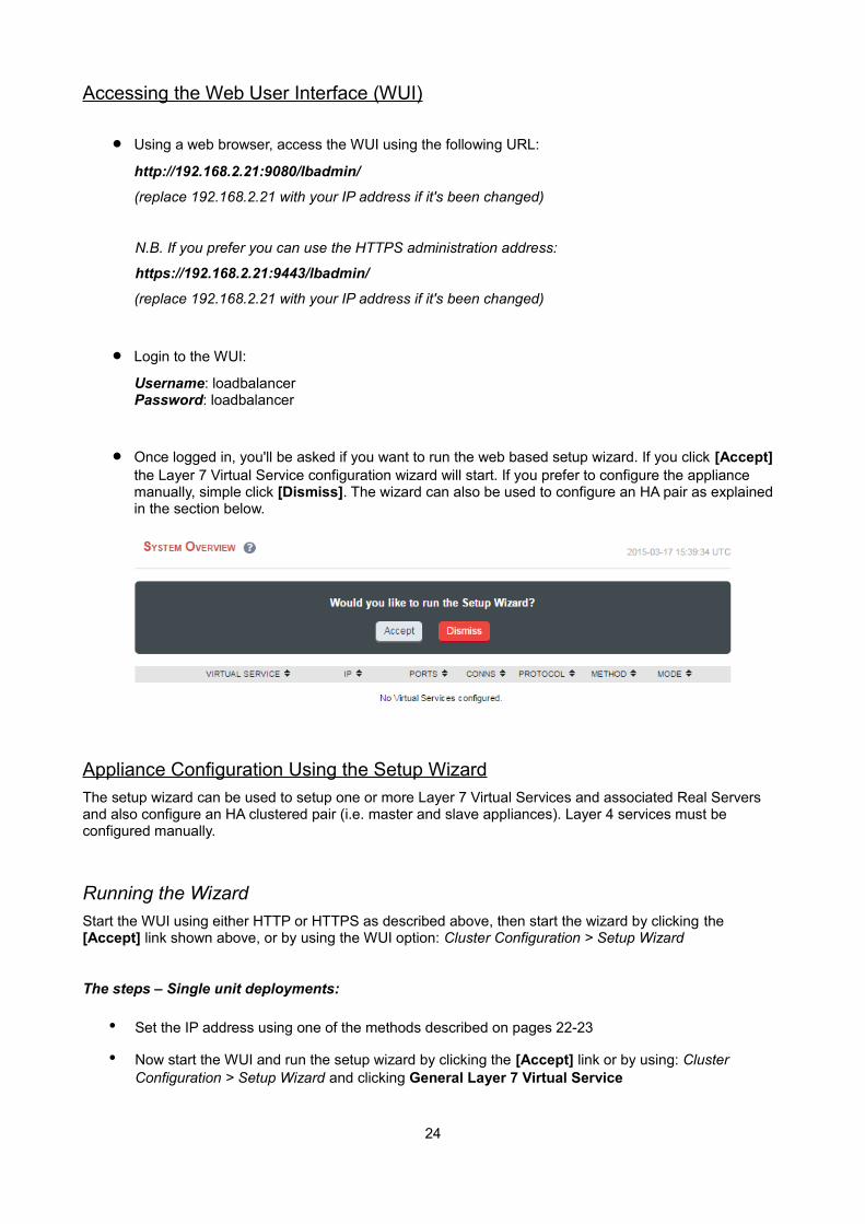
Once logged in, you'll be asked if you want to run the web based setup wizard. If you click [Accept] the Layer 7 Virtual Service configuration wizard will start. If you prefer to configure the appliance manually, simple click [Dismiss]. The wizard can also be used to configure an HA pair as explained in the section below.
Appliance Configuration Using the Setup Wizard
The setup wizard can be used to setup one or more Layer 7 Virtual Services and associated Real Servers and also configure an HA clustered pair (i.e. master and slave appliances). Layer 4 services must be configured manually.
Running the Wizard
Start the WUI using either HTTP or HTTPS as described above, then start the wizard by clicking the [Accept] link shown above, or by using the WUI option: Cluster Configuration > Setup Wizard
The steps – Single unit deployments:
• Set the IP address using one of the methods described on pages 22-23
• Now start the WUI and run the setup wizard by clicking the [Accept] link or by using: Cluster Configuration > Setup Wizard and clicking General Layer 7 Virtual Service
24
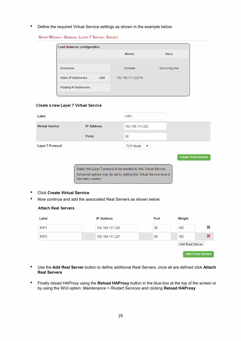
• Define the required Virtual Service settings as shown in the example below:
• Click Create Virtual Service
• Now continue and add the associated Real Servers as shown below:
• Use the Add Real Server button to define additional Real Servers, once all are defined click Attach Real Servers
• Finally reload HAProxy using the Reload HAProxy button in the blue box at the top of the screen or by using the WUI option: Maintenance > Restart Services and clicking Reload HAProxy
25
The steps – Clustered pair deployments:
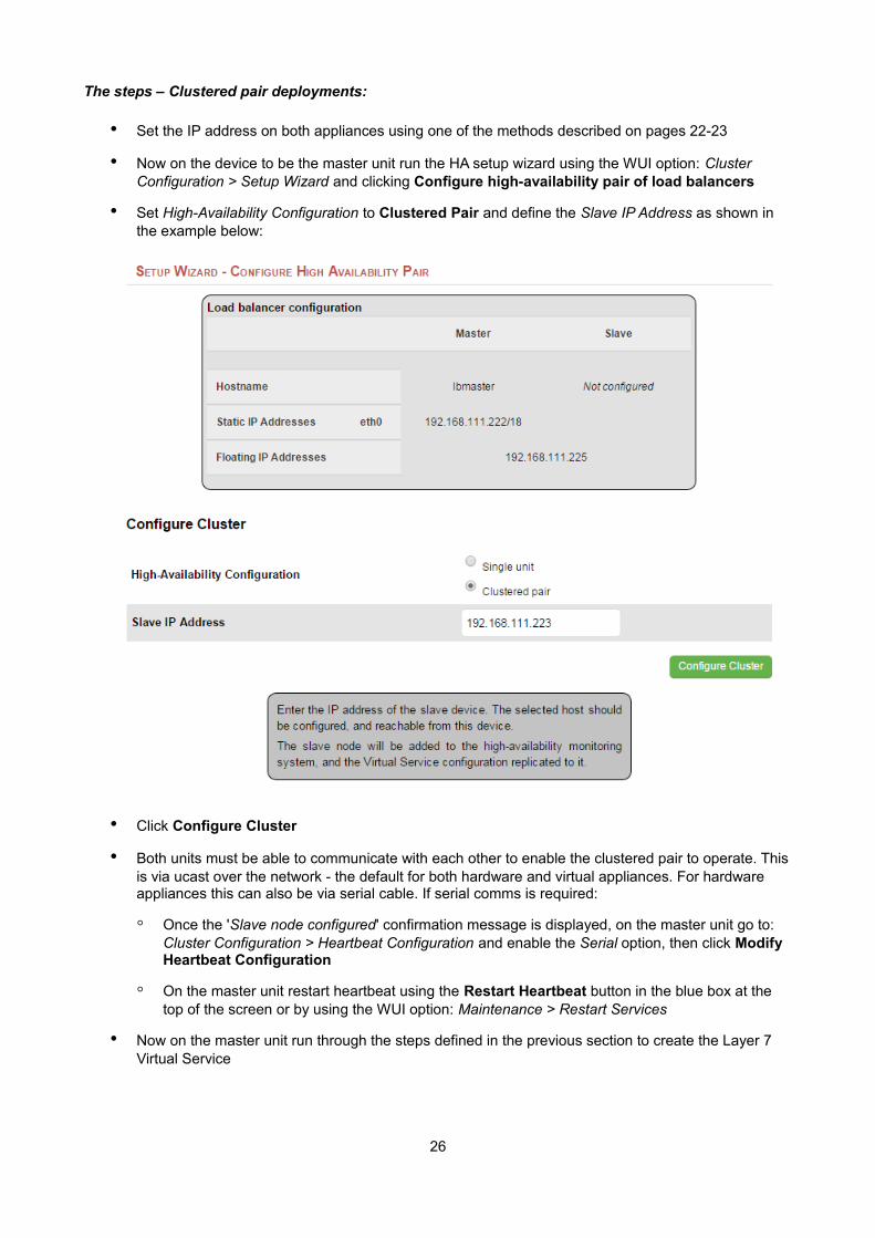
• Set the IP address on both appliances using one of the methods described on pages 22-23
• Now on the device to be the master unit run the HA setup wizard using the WUI option: Cluster Configuration > Setup Wizard and clicking Configure high-availability pair of load balancers
• Set High-Availability Configuration to Clustered Pair and define the Slave IP Address as shown in the example below:
• Click Configure Cluster
• Both units must be able to communicate with each other to enable the clustered pair to operate. Thisis via ucast over the network - the default for both hardware and virtual appliances. For hardware appliances this can also be via serial cable. If serial comms is required:
◦ Once the 'Slave node configured' confirmation message is displayed, on the master unit go to: Cluster Configuration > Heartbeat Configuration and enable the Serial option, then click Modify Heartbeat Configuration
◦ On the master unit restart heartbeat using the Restart Heartbeat button in the blue box at the top of the screen or by using the WUI option: Maintenance > Restart Services
• Now on the master unit run through the steps defined in the previous section to create the Layer 7 Virtual Service
26
NOTE : Running the wizard again will permit additional Layer 7 VIPs and associated RIPs to be defined.
NOTE : To restore manufacturer's settings use the WUI option: Maintenance > Backup & Restore > Restore Manufacturer's Defaults. N.B. this will reset the IP address to 192.168.2.21/24
Appliance Configuration Using the Web User Interface (WUI)
NOTE : For a clustered pair, all configuration must be carried out on the master unit, the slave unit will then be synchronized automatically via the network.
If you have already used the web based wizard, then you will already be using the WUI. From here all administration tasks can be carried out. If not, access the WUI as follows:
With a web browser access the WUI: http://192.168.2.21:9080/lbadmin/
(replace 192.168.2.21 with the correct IP address)
log in to the WUI: Username: loadbalancerPassword: loadbalancer
N.B. If you prefer you can use the HTTPS administration address: https://192.168.2.21:9443/lbadmin/
Once logged in, the WUI is displayed as shown below:
27
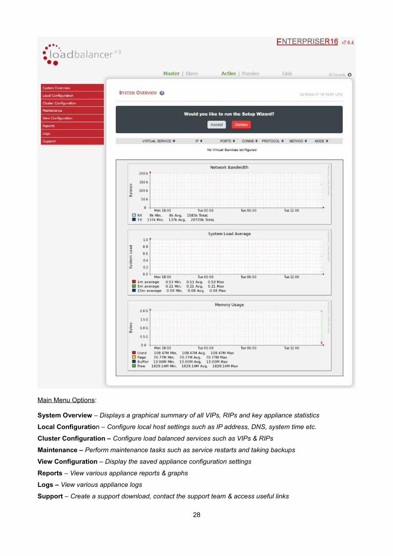
Main Menu Options:
System Overview – Displays a graphical summary of all VIPs, RIPs and key appliance statistics
Local Configuration – Configure local host settings such as IP address, DNS, system time etc.
Cluster Configuration – Configure load balanced services such as VIPs & RIPs
Maintenance – Perform maintenance tasks such as service restarts and taking backups
View Configuration – Display the saved appliance configuration settings
Reports – View various appliance reports & graphs
Logs – View various appliance logs
Support – Create a support download, contact the support team & access useful links
28
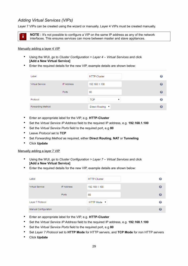
Adding Virtual Services (VIPs)
Layer 7 VIPs can be created using the wizard or manually. Layer 4 VIPs must be created manually.
NOTE : It's not possible to configure a VIP on the same IP address as any of the network interfaces. This ensures services can move between master and slave appliances.
Manually adding a layer 4 VIP
• Using the WUI, go to Cluster Configuration > Layer 4 – Virtual Services and click[Add a New Virtual Service]
• Enter the required details for the new VIP, example details are shown below:
• Enter an appropriate label for the VIP, e.g. HTTP-Cluster
• Set the Virtual Service IP Address field to the required IP address, e.g. 192.168.1.100
• Set the Virtual Service Ports field to the required port, e.g 80
• Leave Protocol set to TCP
• Set Forwarding Method as required, either Direct Routing, NAT or Tunneling
• Click Update
Manually adding a layer 7 VIP
• Using the WUI, go to Cluster Configuration > Layer 7 – Virtual Services and click[Add a New Virtual Service]
• Enter the required details for the new VIP, example details are shown below:
• Enter an appropriate label for the VIP, e.g. HTTP-Cluster
• Set the Virtual Service IP Address field to the required IP address, e.g. 192.168.1.100
• Set the Virtual Service Ports field to the required port, e.g 80
• Set Layer 7 Protocol set to HTTP Mode for HTTP servers, and TCP Mode for non HTTP servers
• Click Update
29
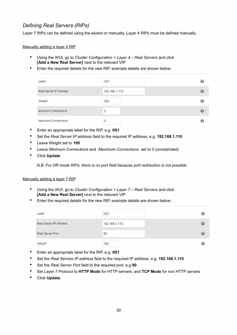
Defining Real Servers (RIPs)
Layer 7 RIPs can be defined using the wizard or manually. Layer 4 RIPs must be defined manually.
Manually adding a layer 4 RIP
• Using the WUI, go to Cluster Configuration > Layer 4 – Real Servers and click[Add a New Real Server] next to the relevant VIP
• Enter the required details for the new RIP, example details are shown below:
• Enter an appropriate label for the RIP, e.g. IIS1
• Set the Real Server IP address field to the required IP address, e.g. 192.168.1.110
• Leave Weight set to 100
• Leave Minimum Connections and Maximum Connections set to 0 (unrestricted)
• Click Update
N.B. For DR mode RIPs, there is no port field because port redirection is not possible
Manually adding a layer 7 RIP
• Using the WUI, go to Cluster Configuration > Layer 7 – Real Servers and click[Add a New Real Server] next to the relevant VIP
• Enter the required details for the new RIP, example details are shown below:
• Enter an appropriate label for the RIP, e.g. IIS1
• Set the Real Service IP address field to the required IP address, e.g. 192.168.1.110
• Set the Real Server Port field to the required port, e.g 80
• Set Layer 7 Protocol to HTTP Mode for HTTP servers, and TCP Mode for non HTTP servers
• Click Update
30
Configuring the Physical Real Servers
Depending on the deployment method (DR, NAT or SNAT) used, the actual physical backend servers may need additional configuration to allow the load balancer to operate correctly. The following sections define what is needed for each mode.
Configuring the Real Servers for Layer 4 NAT Mode
If you are using a two-arm NAT load balancing method, the Real Server configuration is a simple case of configuring the load balancer as the default gateway. Normally, a floating IP address is added using Cluster Configuration > Floating IPs. This is important when a master / slave configuration is used to allow failover & failback of the default gateway address.
NOTE : Failure to correctly configure the Real Servers default gateway is the most common mistake when using NAT mode.
Configuring the Real Servers for Layer 4 DR Mode
When using DR mode, each Real Server (RIP) must be configured to accept packets destined for both the VIP address and the RIP address. This is because in DR mode the destination address of load balanced packets is the VIP address, whilst for other traffic such as health-checks, administration traffic etc. it's the Real Server's own IP address (the RIP). Each Real Server must also be configured so that it does not respond to ARP requests for the VIP address – only the load balancer should do this.
Configuring the Real Servers in this way is referred to as 'Solving the ARP problem'. The steps required depend on the OS used as detailed in the following sections.
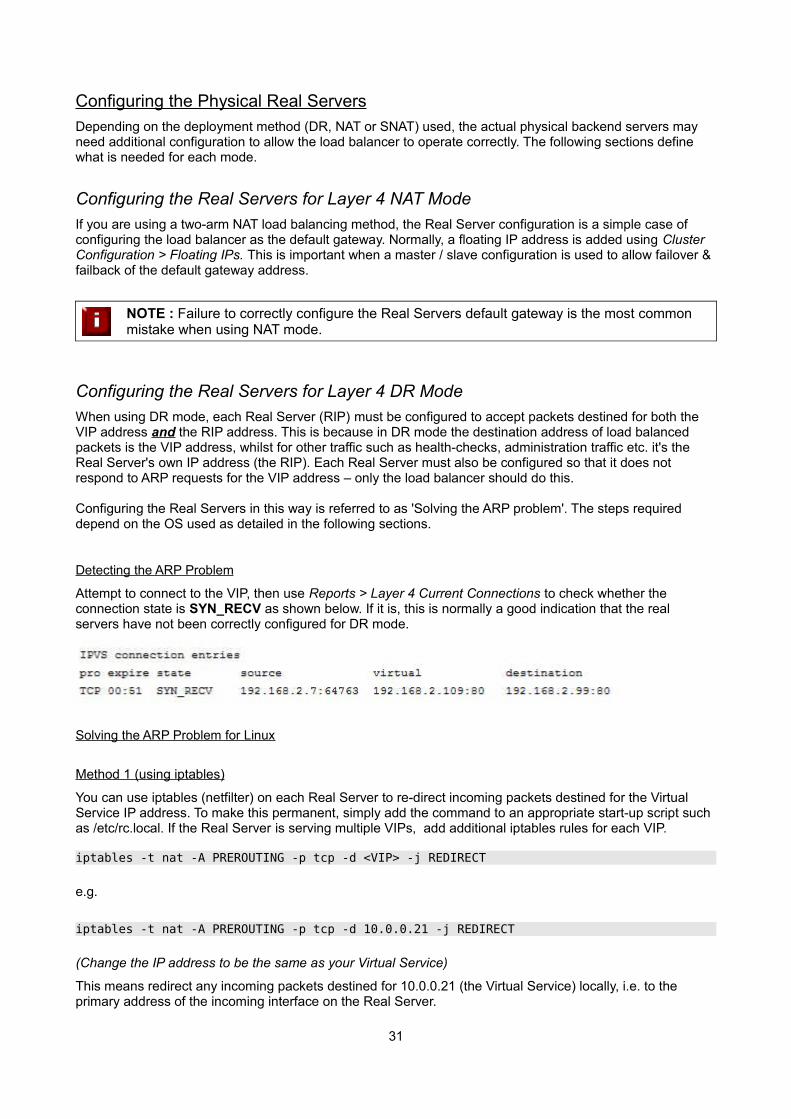
Detecting the ARP Problem
Attempt to connect to the VIP, then use Reports > Layer 4 Current Connections to check whether the connection state is SYN_RECV as shown below. If it is, this is normally a good indication that the real servers have not been correctly configured for DR mode.
Solving the ARP Problem for Linux
Method 1 (using iptables)
You can use iptables (netfilter) on each Real Server to re-direct incoming packets destined for the Virtual Service IP address. To make this permanent, simply add the command to an appropriate start-up script such as /etc/rc.local. If the Real Server is serving multiple VIPs, add additional iptables rules for each VIP.
iptables -t nat -A PREROUTING -p tcp -d <VIP> -j REDIRECT
e.g.
iptables -t nat -A PREROUTING -p tcp -d 10.0.0.21 -j REDIRECT
(Change the IP address to be the same as your Virtual Service)
This means redirect any incoming packets destined for 10.0.0.21 (the Virtual Service) locally, i.e. to the primary address of the incoming interface on the Real Server.
31
NOTE : Method 1 may not always be appropriate if you're using IP-based virtual hosting on your web server. This is because the iptables rule above redirects incoming packets to the primary address of the incoming interface on the web server rather than any of the virtual hoststhat are configured. Where this is an issue, use method 2 below instead.
Also, Method 1 does not work with IPv6 Virtual Services, use method 2 below instead.
Method 2 (using arp_ignore sysctl values)
This is the preferred method as it supports both IPv4 and IPv6. Each Real Server needs the loopback adapter to be configured with the Virtual Services IP address. This address must not respond to ARP requests and the web server also needs to be configured to respond to this address. To set this up follow steps 1-4 below.
Step 1: re-configure ARP on the Real Servers (this step can be skipped for IPv6 Virtual Services)
To do this add the following lines to /etc/sysctl.conf:
net.ipv4.conf.all.arp_ignore=1 net.ipv4.conf.eth0.arp_ignore=1 net.ipv4.conf.eth1.arp_ignore=1 net.ipv4.conf.all.arp_announce=2 net.ipv4.conf.eth0.arp_announce=2 net.ipv4.conf.eth1.arp_announce=2
Step 2: re-configure DAD on the Real Servers (this step can be skipped for IPv4 Virtual Services)
net.ipv6.conf.lo.dad_transmits=0net.ipv6.conf.lo.accept_dad=0
Step 3: apply these settings
Either reboot the Real Server or run the following command to apply these settings:
/sbin/sysctl -p
Step 4: add the Virtual Services IP address to the loopback adapter
Run the following command for each VIP. To make this permanent, simply add the command to an appropriate startup script such as /etc/rc.local.
ip addr add dev lo <IPv4-VIP>/32
for IPv6 addresses use:
ip addr add dev lo <IPv6-VIP>/128
32
N.B. Steps 1, 2 & 3 can be replaced by writing directly to the required files using the following commands:
(temporary until the next reboot)
echo 1 > /proc/sys/net/ipv4/conf/all/arp_ignoreecho 1 > /proc/sys/net/ipv4/conf/eth0/arp_ignoreecho 1 > /proc/sys/net/ipv4/conf/eth1/arp_ignoreecho 2 > /proc/sys/net/ipv4/conf/all/arp_announceecho 2 > /proc/sys/net/ipv4/conf/eth0/arp_announceecho 2 > /proc/sys/net/ipv4/conf/eth1/arp_announceecho 0 > /proc/sys/net/ipv6/conf/lo/dad_transmitsecho 0 > /proc/sys/net/ipv6/conf/lo/accept_dad
Solving the ARP Problem for Solaris & MAC OS X / BSD
Solaris:
With Solaris the loopback interface does not respond to ARP requests so you just add your VIPs to it.
ifconfig lo0:1 plumbifconfig lo0:1 VIP netmask 255.255.255.255 up
You will need to add this to the startup scripts for your server.
MAC OS X or BSD:
OS X is BSDish, so you need to use BSDish syntax:
ifconfig lo0 alias VIP netmask 255.255.255.255 -arp up
You will need to add this to the startup scripts for your server.
NOTE : Don't forget that the service on the Real Servers needs to listen on both the RIP address and VIP address as mentioned previously.
NOTE : Failure to correctly configure the Real Servers to handle the ARP problem is the most common mistake in DR mode configurations.
33
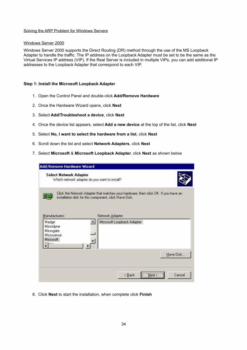
Solving the ARP Problem for Windows Servers
Windows Server 2000
Windows Server 2000 supports the Direct Routing (DR) method through the use of the MS Loopback Adapter to handle the traffic. The IP address on the Loopback Adapter must be set to be the same as the Virtual Services IP address (VIP). If the Real Server is included in multiple VIPs, you can add additional IP addresses to the Loopback Adapter that correspond to each VIP.
Step 1: Install the Microsoft Loopback Adapter
1. Open the Control Panel and double-click Add/Remove Hardware
2. Once the Hardware Wizard opens, click Next
3. Select Add/Troubleshoot a device, click Next
4. Once the device list appears, select Add a new device at the top of the list, click Next
5. Select No, I want to select the hardware from a list, click Next
6. Scroll down the list and select Network Adapters, click Next
7. Select Microsoft & Microsoft Loopback Adapter, click Next as shown below
8. Click Next to start the installation, when complete click Finish
34
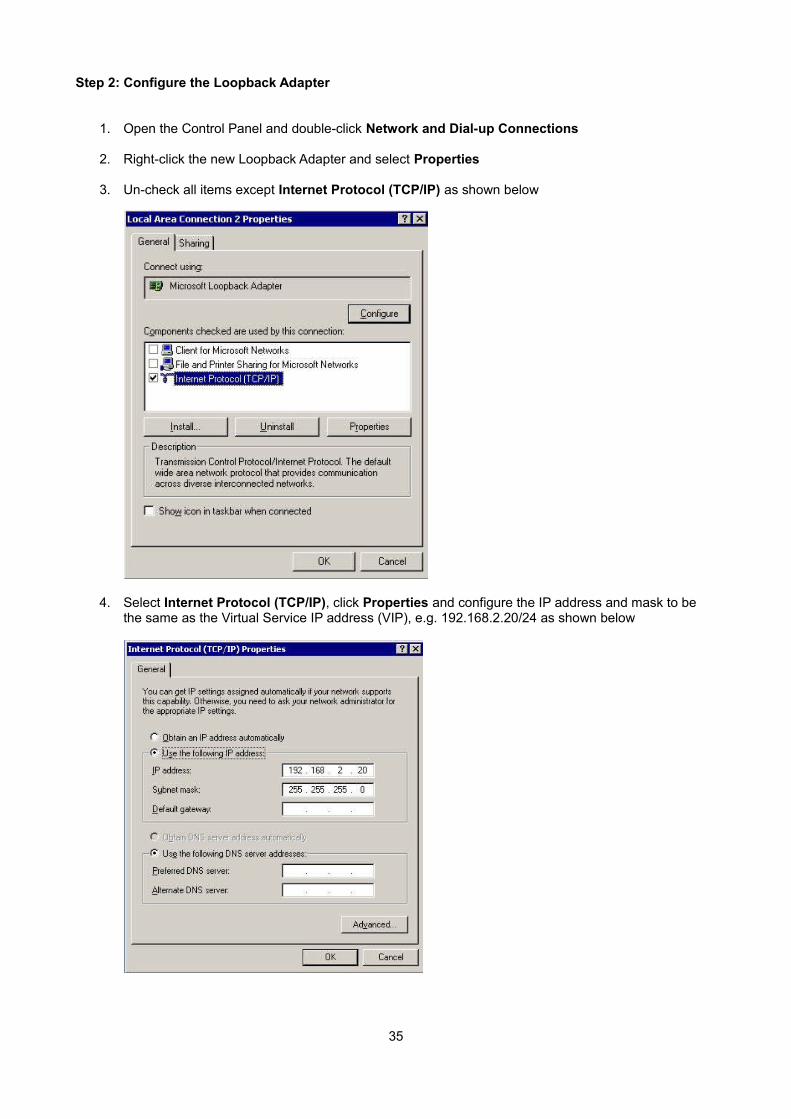
Step 2: Configure the Loopback Adapter
1. Open the Control Panel and double-click Network and Dial-up Connections
2. Right-click the new Loopback Adapter and select Properties
3. Un-check all items except Internet Protocol (TCP/IP) as shown below
4. Select Internet Protocol (TCP/IP), click Properties and configure the IP address and mask to be the same as the Virtual Service IP address (VIP), e.g. 192.168.2.20/24 as shown below
35
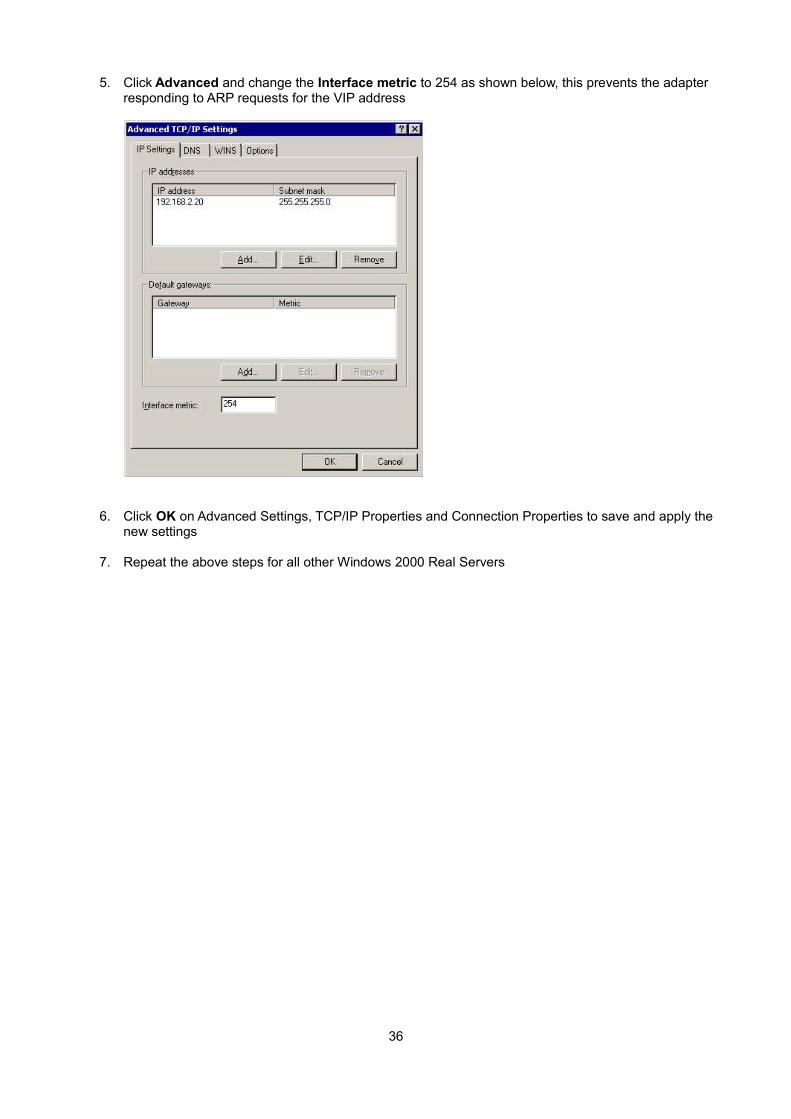
5. Click Advanced and change the Interface metric to 254 as shown below, this prevents the adapter responding to ARP requests for the VIP address
6. Click OK on Advanced Settings, TCP/IP Properties and Connection Properties to save and apply thenew settings
7. Repeat the above steps for all other Windows 2000 Real Servers
36
Windows Server 2003
Windows server 2003 supports the Direct Routing (DR) method through the use of the MS Loopback Adapterto handle the traffic. The IP address on the Loopback Adapter must be set to be the same as the Virtual Services IP address (VIP). If the Real Server is included in multiple VIPs, you can add additional IP addresses to the Loopback Adapter that correspond to each VIP.
Step 1: Install the Microsoft Loopback Adapter
1. Open the Control Panel and double-click Add Hardware
2. Once the Hardware Wizard opens, click Next
3. Select Yes, I have already connected the hardware, click Next
4. Scroll to the bottom of the list, select Add a new hardware device, click Next
5. Select Install the hardware that I manually select from a list (Advanced), click Next
6. Select Network adapters, click Next
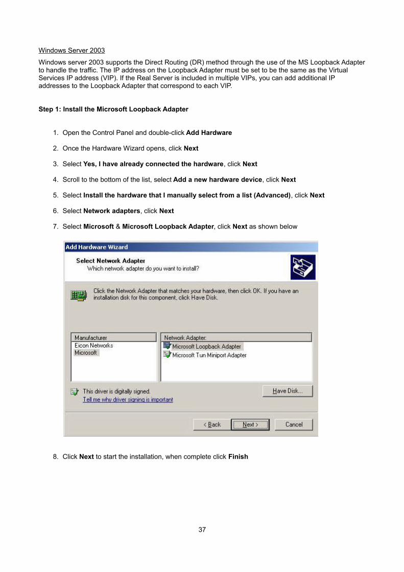
7. Select Microsoft & Microsoft Loopback Adapter, click Next as shown below
8. Click Next to start the installation, when complete click Finish
37
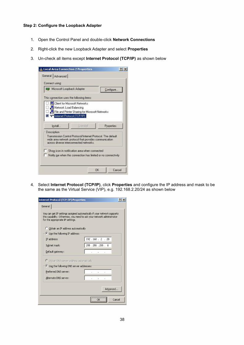
Step 2: Configure the Loopback Adapter
1. Open the Control Panel and double-click Network Connections
2. Right-click the new Loopback Adapter and select Properties
3. Un-check all items except Internet Protocol (TCP/IP) as shown below
4. Select Internet Protocol (TCP/IP), click Properties and configure the IP address and mask to be the same as the Virtual Service (VIP), e.g. 192.168.2.20/24 as shown below
38
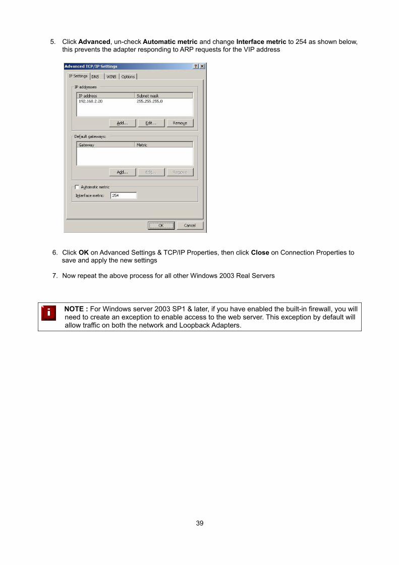
5. Click Advanced, un-check Automatic metric and change Interface metric to 254 as shown below, this prevents the adapter responding to ARP requests for the VIP address
6. Click OK on Advanced Settings & TCP/IP Properties, then click Close on Connection Properties to save and apply the new settings
7. Now repeat the above process for all other Windows 2003 Real Servers
NOTE : For Windows server 2003 SP1 & later, if you have enabled the built-in firewall, you willneed to create an exception to enable access to the web server. This exception by default will allow traffic on both the network and Loopback Adapters.
39
Windows Server 2008
The basic concept is the same as for Windows 2000 / 2003. However, additional steps are required to set thestrong / weak host behavior. This is used to either block or allow interfaces receiving packets destined for a different interface on the same server. As with Windows 2000 / 2003, if the Real Server is included in multipleVIPs, you can add additional IP addresses to the Loopback Adapter that correspond to each VIP.
Step 1: Install the Microsoft Loopback Adapter
1. Click Start, then run hdwwiz to start the Hardware Installation Wizard
2. When the Wizard has started, click Next
3. Select Install the hardware that I manually select from a list (Advanced), click Next
4. Select Network adapters, click Next
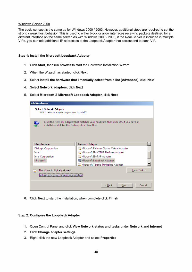
5. Select Microsoft & Microsoft Loopback Adapter, click Next
6. Click Next to start the installation, when complete click Finish
Step 2: Configure the Loopback Adapter
1. Open Control Panel and click View Network status and tasks under Network and internet
2. Click Change adapter settings
3. Right-click the new Loopback Adapter and select Properties
40
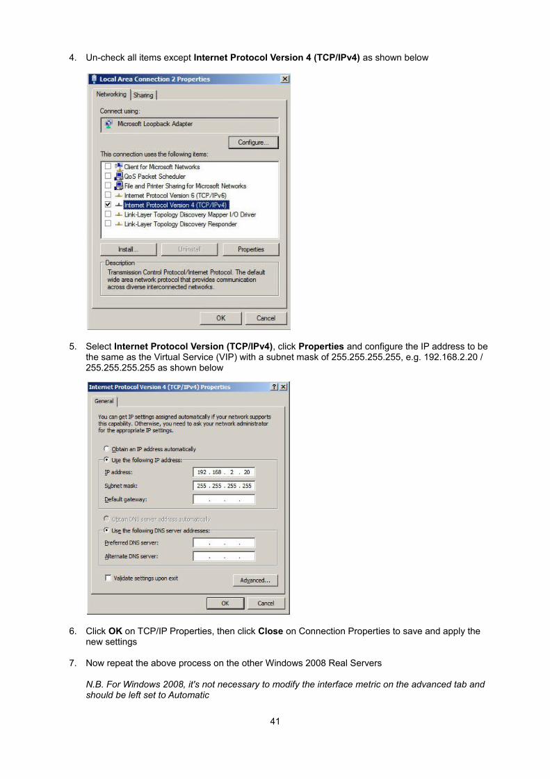
4. Un-check all items except Internet Protocol Version 4 (TCP/IPv4) as shown below
5. Select Internet Protocol Version (TCP/IPv4), click Properties and configure the IP address to be the same as the Virtual Service (VIP) with a subnet mask of 255.255.255.255, e.g. 192.168.2.20 / 255.255.255.255 as shown below
6. Click OK on TCP/IP Properties, then click Close on Connection Properties to save and apply the new settings
7. Now repeat the above process on the other Windows 2008 Real Servers
N.B. For Windows 2008, it's not necessary to modify the interface metric on the advanced tab and should be left set to Automatic
41
Step 3: Configure the strong / weak host behavior
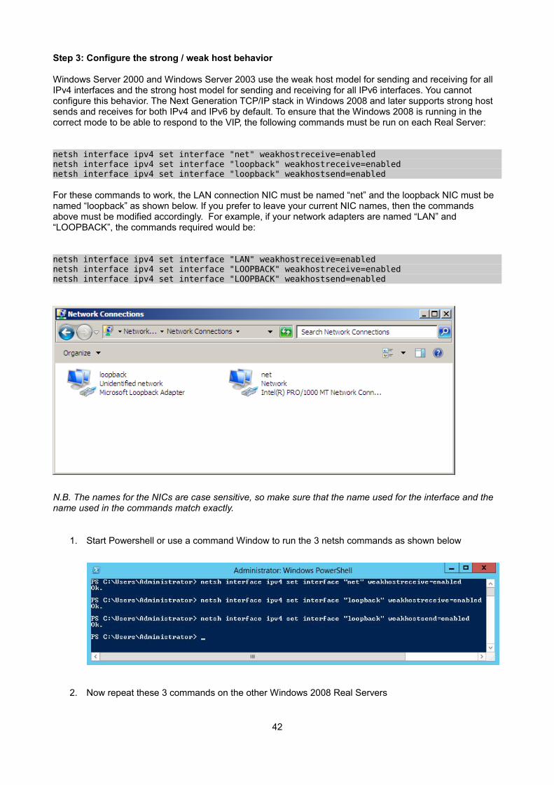
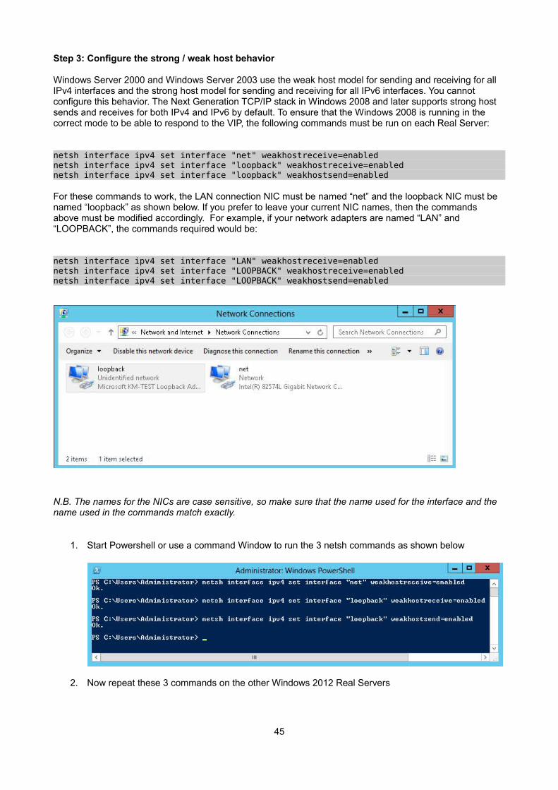
Windows Server 2000 and Windows Server 2003 use the weak host model for sending and receiving for all IPv4 interfaces and the strong host model for sending and receiving for all IPv6 interfaces. You cannot configure this behavior. The Next Generation TCP/IP stack in Windows 2008 and later supports strong host sends and receives for both IPv4 and IPv6 by default. To ensure that the Windows 2008 is running in the correct mode to be able to respond to the VIP, the following commands must be run on each Real Server:
netsh interface ipv4 set interface "net" weakhostreceive=enabled netsh interface ipv4 set interface "loopback" weakhostreceive=enabled netsh interface ipv4 set interface "loopback" weakhostsend=enabled
For these commands to work, the LAN connection NIC must be named “net” and the loopback NIC must be named “loopback” as shown below. If you prefer to leave your current NIC names, then the commands above must be modified accordingly. For example, if your network adapters are named “LAN” and “LOOPBACK”, the commands required would be:
netsh interface ipv4 set interface "LAN" weakhostreceive=enabled netsh interface ipv4 set interface "LOOPBACK" weakhostreceive=enabled netsh interface ipv4 set interface "LOOPBACK" weakhostsend=enabled
N.B. The names for the NICs are case sensitive, so make sure that the name used for the interface and the name used in the commands match exactly.
1. Start Powershell or use a command Window to run the 3 netsh commands as shown below
2. Now repeat these 3 commands on the other Windows 2008 Real Servers
42
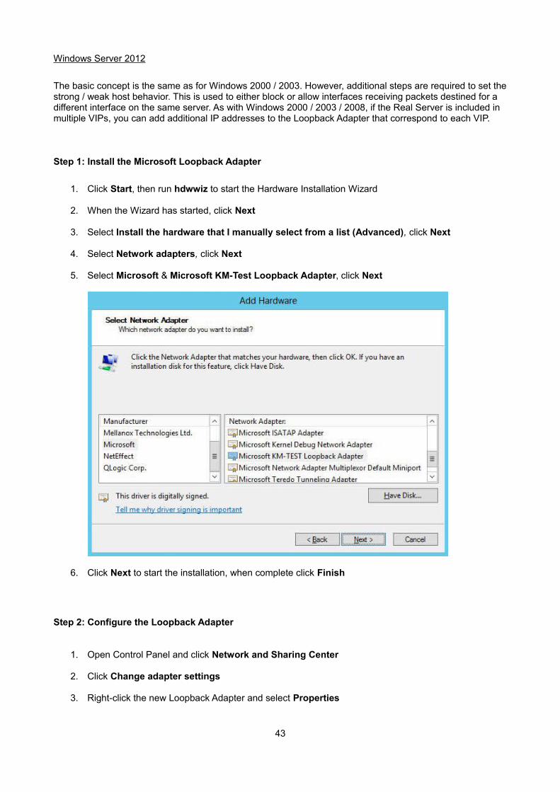
Windows Server 2012
The basic concept is the same as for Windows 2000 / 2003. However, additional steps are required to set thestrong / weak host behavior. This is used to either block or allow interfaces receiving packets destined for a different interface on the same server. As with Windows 2000 / 2003 / 2008, if the Real Server is included in multiple VIPs, you can add additional IP addresses to the Loopback Adapter that correspond to each VIP.
Step 1: Install the Microsoft Loopback Adapter
1. Click Start, then run hdwwiz to start the Hardware Installation Wizard
2. When the Wizard has started, click Next
3. Select Install the hardware that I manually select from a list (Advanced), click Next
4. Select Network adapters, click Next
5. Select Microsoft & Microsoft KM-Test Loopback Adapter, click Next
6. Click Next to start the installation, when complete click Finish
Step 2: Configure the Loopback Adapter
1. Open Control Panel and click Network and Sharing Center
2. Click Change adapter settings
3. Right-click the new Loopback Adapter and select Properties
43
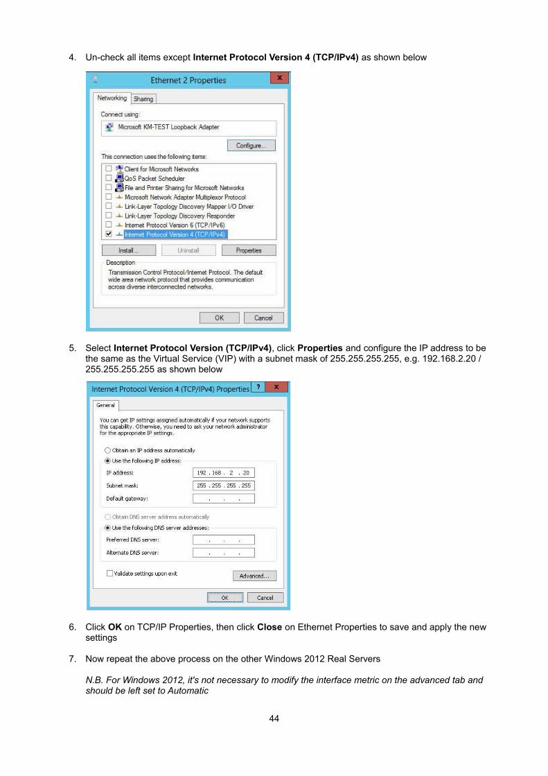
4. Un-check all items except Internet Protocol Version 4 (TCP/IPv4) as shown below
5. Select Internet Protocol Version (TCP/IPv4), click Properties and configure the IP address to be the same as the Virtual Service (VIP) with a subnet mask of 255.255.255.255, e.g. 192.168.2.20 / 255.255.255.255 as shown below
6. Click OK on TCP/IP Properties, then click Close on Ethernet Properties to save and apply the new settings
7. Now repeat the above process on the other Windows 2012 Real Servers
N.B. For Windows 2012, it's not necessary to modify the interface metric on the advanced tab and should be left set to Automatic
44
Step 3: Configure the strong / weak host behavior
Windows Server 2000 and Windows Server 2003 use the weak host model for sending and receiving for all IPv4 interfaces and the strong host model for sending and receiving for all IPv6 interfaces. You cannot configure this behavior. The Next Generation TCP/IP stack in Windows 2008 and later supports strong host sends and receives for both IPv4 and IPv6 by default. To ensure that the Windows 2008 is running in the correct mode to be able to respond to the VIP, the following commands must be run on each Real Server:
netsh interface ipv4 set interface "net" weakhostreceive=enabled netsh interface ipv4 set interface "loopback" weakhostreceive=enabled netsh interface ipv4 set interface "loopback" weakhostsend=enabled
For these commands to work, the LAN connection NIC must be named “net” and the loopback NIC must be named “loopback” as shown below. If you prefer to leave your current NIC names, then the commands above must be modified accordingly. For example, if your network adapters are named “LAN” and “LOOPBACK”, the commands required would be:
netsh interface ipv4 set interface "LAN" weakhostreceive=enabled netsh interface ipv4 set interface "LOOPBACK" weakhostreceive=enabled netsh interface ipv4 set interface "LOOPBACK" weakhostsend=enabled
N.B. The names for the NICs are case sensitive, so make sure that the name used for the interface and the name used in the commands match exactly.
1. Start Powershell or use a command Window to run the 3 netsh commands as shown below
2. Now repeat these 3 commands on the other Windows 2012 Real Servers
45
Verifying netsh Settings for Windows 2008 & 2012
To verify that settings have been configured correctly, run the following command on each Real Server to clearly list the settings that have been applied to the interface:
netsh interface ipv4 show interface <interface name>
i.e.
for the 'loopback' adapter run: netsh interface ipv4 show interface loopback
for the 'net' adapter run: netsh interface ipv4 show interface net
e.g.
This shows that the settings have been applied correctly.
NOTE : For Windows server 2008 / 2012, if you want to leave the built-in firewall enabled, you'll either need to enable the relevant default firewall exceptions or create your own to enable access to the web server. By default these exceptions will allow traffic on both the network and loopback adapters.
NOTE : Failure to correctly configure the Real Servers to handle the ARP problem is the most common problem in DR configurations.
46
Configuring the Application/Service to Respond to both the RIP and VIP
For DR & TUN modes, it's also important to make sure that the application running on the Real Servers (e.g. IIS) responds to both the VIP and RIP addresses.
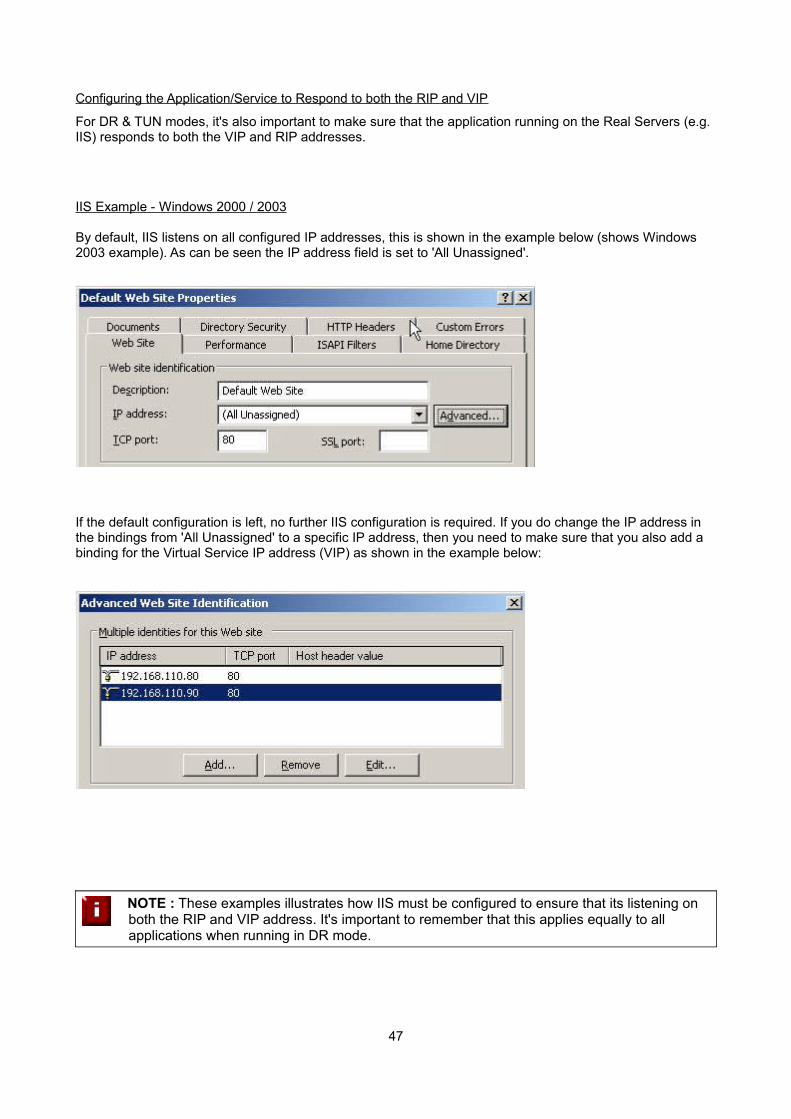
IIS Example - Windows 2000 / 2003
By default, IIS listens on all configured IP addresses, this is shown in the example below (shows Windows 2003 example). As can be seen the IP address field is set to 'All Unassigned'.
If the default configuration is left, no further IIS configuration is required. If you do change the IP address in the bindings from 'All Unassigned' to a specific IP address, then you need to make sure that you also add a binding for the Virtual Service IP address (VIP) as shown in the example below:
NOTE : These examples illustrates how IIS must be configured to ensure that its listening on both the RIP and VIP address. It's important to remember that this applies equally to all applications when running in DR mode.
47
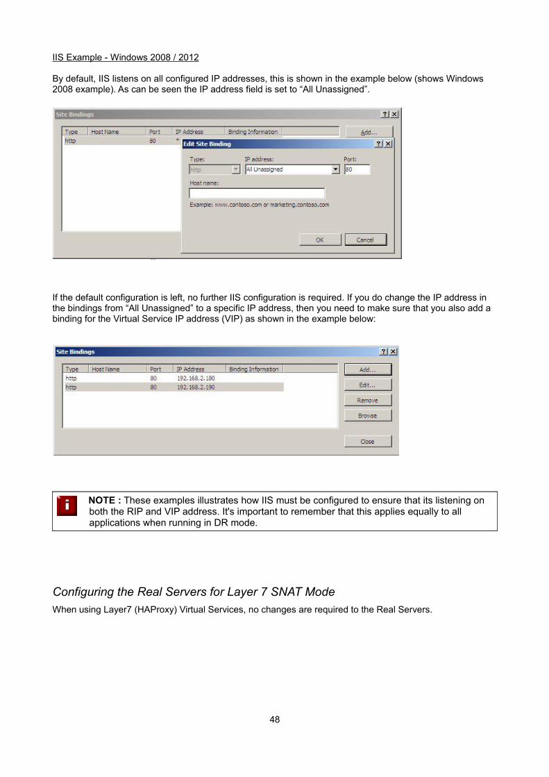
IIS Example - Windows 2008 / 2012
By default, IIS listens on all configured IP addresses, this is shown in the example below (shows Windows 2008 example). As can be seen the IP address field is set to “All Unassigned”.
If the default configuration is left, no further IIS configuration is required. If you do change the IP address in the bindings from “All Unassigned” to a specific IP address, then you need to make sure that you also add a binding for the Virtual Service IP address (VIP) as shown in the example below:
NOTE : These examples illustrates how IIS must be configured to ensure that its listening on both the RIP and VIP address. It's important to remember that this applies equally to all applications when running in DR mode.
Configuring the Real Servers for Layer 7 SNAT Mode
When using Layer7 (HAProxy) Virtual Services, no changes are required to the Real Servers.
48
IPv6 Support
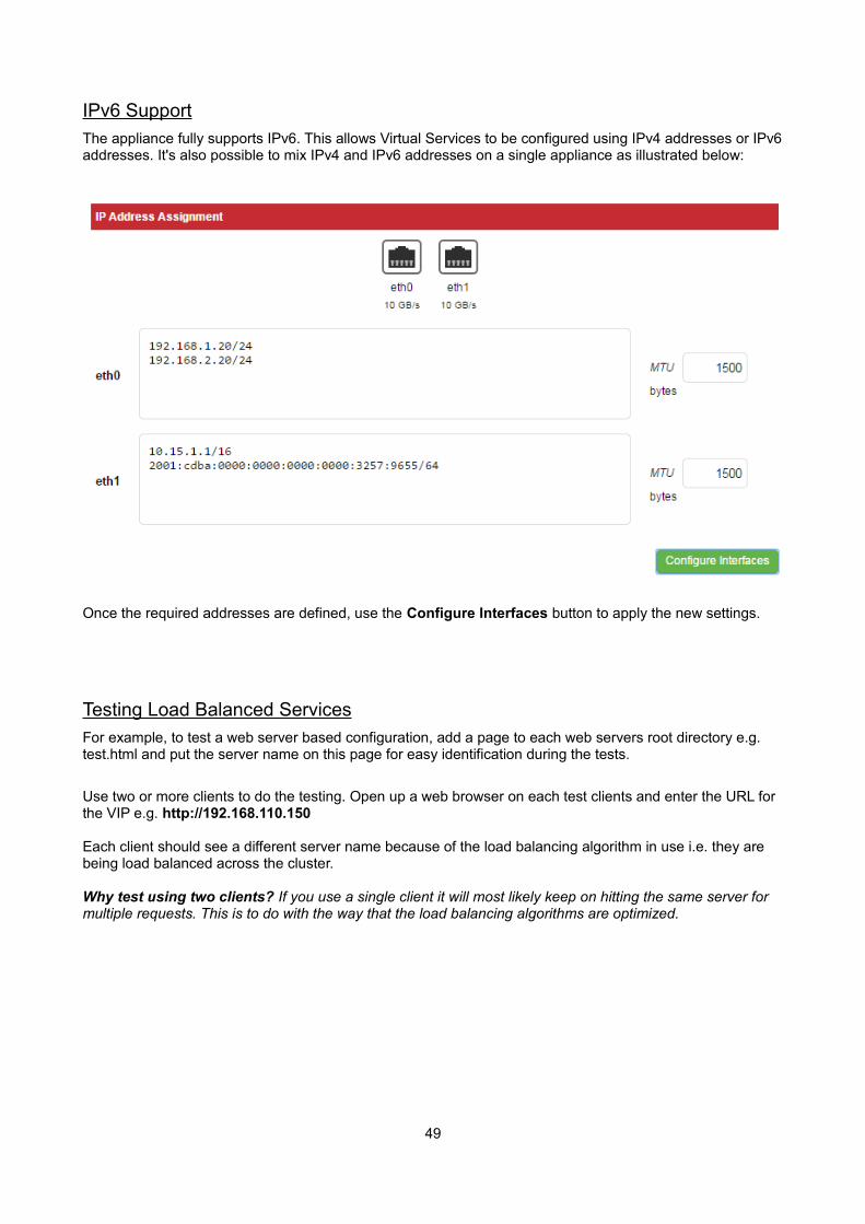
The appliance fully supports IPv6. This allows Virtual Services to be configured using IPv4 addresses or IPv6addresses. It's also possible to mix IPv4 and IPv6 addresses on a single appliance as illustrated below:
Once the required addresses are defined, use the Configure Interfaces button to apply the new settings.
Testing Load Balanced Services
For example, to test a web server based configuration, add a page to each web servers root directory e.g. test.html and put the server name on this page for easy identification during the tests.
Use two or more clients to do the testing. Open up a web browser on each test clients and enter the URL for the VIP e.g. http://192.168.110.150
Each client should see a different server name because of the load balancing algorithm in use i.e. they are being load balanced across the cluster.
Why test using two clients? If you use a single client it will most likely keep on hitting the same server for multiple requests. This is to do with the way that the load balancing algorithms are optimized.
49
Diagnosing VIP Connection Problems
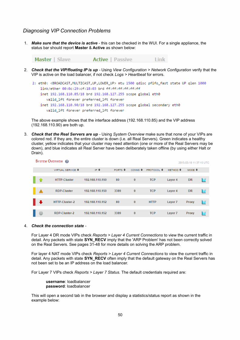
1. Make sure that the device is active - this can be checked in the WUI. For a single appliance, the status bar should report Master & Active as shown below:
2. Check that the VIP/floating IP is up - Using View Configuration > Network Configuration verify that theVIP is active on the load balancer, if not check Logs > Heartbeat for errors.
The above example shows that the interface address (192.168.110.85) and the VIP address (192.168.110.90) are both up.
3. Check that the Real Servers are up - Using System Overview make sure that none of your VIPs are colored red. If they are, the entire cluster is down (i.e. all Real Servers). Green indicates a healthy cluster, yellow indicates that your cluster may need attention (one or more of the Real Servers may be down), and blue indicates all Real Server have been deliberately taken offline (by using either Halt or Drain).
4. Check the connection state -
For Layer 4 DR mode VIPs check Reports > Layer 4 Current Connections to view the current traffic in detail. Any packets with state SYN_RECV imply that the 'ARP Problem' has not been correctly solved on the Real Servers. See pages 31-48 for more details on solving the ARP problem.
For layer 4 NAT mode VIPs check Reports > Layer 4 Current Connections to view the current traffic in detail. Any packets with state SYN_RECV often imply that the default gateway on the Real Servers has not been set to be an IP address on the load balancer.
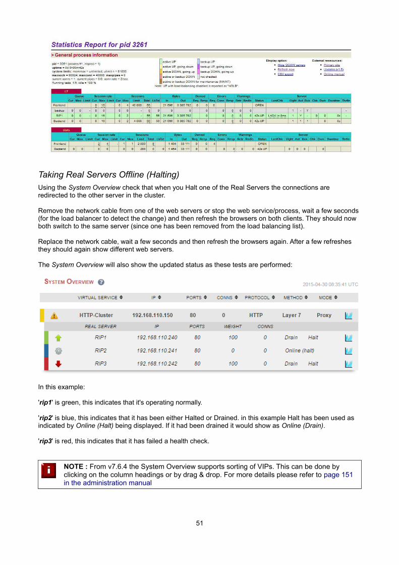
For Layer 7 VIPs check Reports > Layer 7 Status. The default credentials required are:
username: loadbalancerpassword: loadbalancer
This will open a second tab in the browser and display a statistics/status report as shown in theexample below:
50
Taking Real Servers Offline (Halting)
Using the System Overview check that when you Halt one of the Real Servers the connections are redirected to the other server in the cluster.
Remove the network cable from one of the web servers or stop the web service/process, wait a few seconds (for the load balancer to detect the change) and then refresh the browsers on both clients. They should now both switch to the same server (since one has been removed from the load balancing list).
Replace the network cable, wait a few seconds and then refresh the browsers again. After a few refreshes they should again show different web servers.
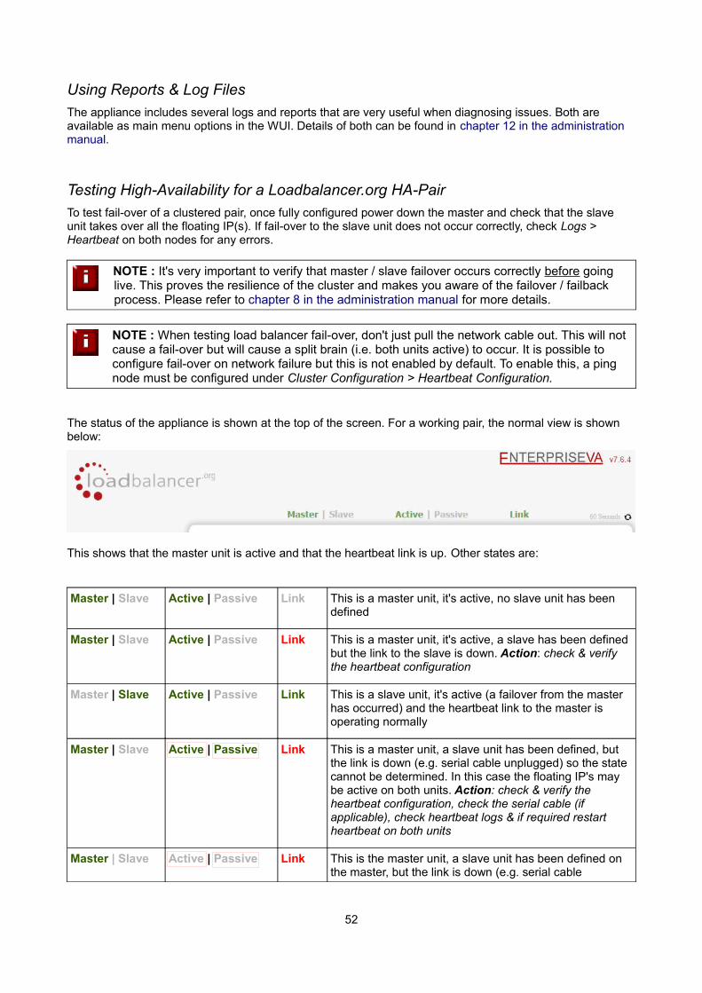
The System Overview will also show the updated status as these tests are performed:
In this example:
'rip1' is green, this indicates that it's operating normally.
'rip2' is blue, this indicates that it has been either Halted or Drained. in this example Halt has been used as indicated by Online (Halt) being displayed. If it had been drained it would show as Online (Drain).
'rip3' is red, this indicates that it has failed a health check.
NOTE : From v7.6.4 the System Overview supports sorting of VIPs. This can be done by clicking on the column headings or by drag & drop. For more details please refer to page 151 in the administration manual
51
Using Reports & Log Files
The appliance includes several logs and reports that are very useful when diagnosing issues. Both are available as main menu options in the WUI. Details of both can be found in chapter 12 in the administration manual.
Testing High-Availability for a Loadbalancer.org HA-Pair
To test fail-over of a clustered pair, once fully configured power down the master and check that the slave unit takes over all the floating IP(s). If fail-over to the slave unit does not occur correctly, check Logs > Heartbeat on both nodes for any errors.
NOTE : It's very important to verify that master / slave failover occurs correctly before going live. This proves the resilience of the cluster and makes you aware of the failover / failback process. Please refer to chapter 8 in the administration manual for more details.
NOTE : When testing load balancer fail-over, don't just pull the network cable out. This will not cause a fail-over but will cause a split brain (i.e. both units active) to occur. It is possible to configure fail-over on network failure but this is not enabled by default. To enable this, a ping node must be configured under Cluster Configuration > Heartbeat Configuration.
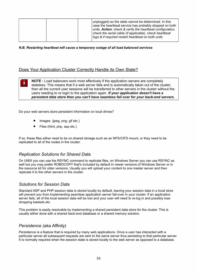
The status of the appliance is shown at the top of the screen. For a working pair, the normal view is shown below:
This shows that the master unit is active and that the heartbeat link is up. Other states are:
Master | Slave Active | Passive Link This is a master unit, it's active, no slave unit has been defined
Master | Slave Active | Passive Link This is a master unit, it's active, a slave has been defined but the link to the slave is down. Action: check & verify the heartbeat configuration
Master | Slave Active | Passive Link This is a slave unit, it's active (a failover from the master has occurred) and the heartbeat link to the master is operating normally
Master | Slave Active | Passive Link This is a master unit, a slave unit has been defined, but the link is down (e.g. serial cable unplugged) so the state cannot be determined. In this case the floating IP's may be active on both units. Action: check & verify the heartbeat configuration, check the serial cable (if applicable), check heartbeat logs & if required restart heartbeat on both units
Master | Slave Active | Passive Link This is the master unit, a slave unit has been defined on the master, but the link is down (e.g. serial cable
52
unplugged) so the state cannot be determined. In this case the heartbeat service has probably stopped on both units. Action: check & verify the heartbeat configuration, check the serial cable (if applicable), check heartbeat logs & if required restart heartbeat on both units
N.B. Restarting heartbeat will cause a temporary outage of all load balanced services
Does Your Application Cluster Correctly Handle its Own State?
NOTE : Load balancers work most effectively if the application servers are completely stateless. This means that if a web server fails and is automatically taken out of the cluster; then all the current user sessions will be transferred to other servers in the cluster without the users needing to re login to the application again. If your application doesn't have a persistent data store then you can't have seamless fail over for your back-end servers.
Do your web servers store persistent information on local drives?
Images (jpeg, png, gif etc.)
Files (html, php, asp etc.)
If so, these files either need to be on shared storage such as an NFS/CIFS mount, or they need to be replicated to all of the nodes in the cluster.
Replication Solutions for Shared Data
On UNIX you can use the RSYNC command to replicate files, on Windows Server you can use RSYNC as well but you may prefer ROBOCOPY that's included by default in newer versions of Windows Server or in the resource kit for older versions. Usually you will upload your content to one master server and then replicate it to the other servers in the cluster.
Solutions for Session Data
Standard ASP and PHP session data is stored locally by default, leaving your session data in a local store will prevent you from implementing seamless application server fail-over in your cluster. If an application server fails, all of the local session data will be lost and your user will need to re-log in and possibly lose shopping baskets etc.
This problem is easily resolvable by implementing a shared persistent data store for the cluster. This is usually either done with a shared back-end database or a shared memory solution.
Persistence (aka Affinity)
Persistence is a feature that is required by many web applications. Once a user has interacted with a particular server all subsequent requests are sent to the same server thus persisting to that particular server. It is normally required when the session state is stored locally to the web server as opposed to a database.
53
What do You do if Your Application is not Stateless?
Some applications require state to be maintained such as:
Terminal Services / Remote Desktop Services
SSH
FTP (upload)
SMTP (incoming)
You may also find that you are unable to modify your HTTP/HTTPS based application to handle shared session data.
For these cases, you can use persistence based on source IP address. You lose the ability to have transparent fail-over, but you do still get increased capacity and manageability. This persistence problem occurs with all load balancers and all vendors use standard methods and technologies to mitigate the issue.
Loadbalancer.org Persistence Options
Source IP (subnet)
Cookie (Active or Passive)
SSL session ID
Microsoft Connection Broker / Session Broker Integration
The standard Layer 4 persistence method is source IP persistence, you can handle millions of persistent connections at Layer 4. Just modify your Virtual Service to be persistent if you require source IP persistence.
Cookies are a Layer 7 based persistence method that can offer more even traffic distribution and also handleany clients where the source IP address may change during the session (e.g. mega proxies).
SSL session ID based persistence is useful in certain circumstances, although due to the way some browsers operate – notably Internet Explorer, the session ID can be renegotiated frequently which effectively breaks the persistence.
Loadbalancer.org Technical Support
If you have any questions regarding the appliance don't hesitate to contact the support team via their email address: [email protected] or your local reseller.
For more details please refer to the administration manual:
http://pdfs.loadbalancer.org/v7/loadbalanceradministrationv7.6.pdf
54
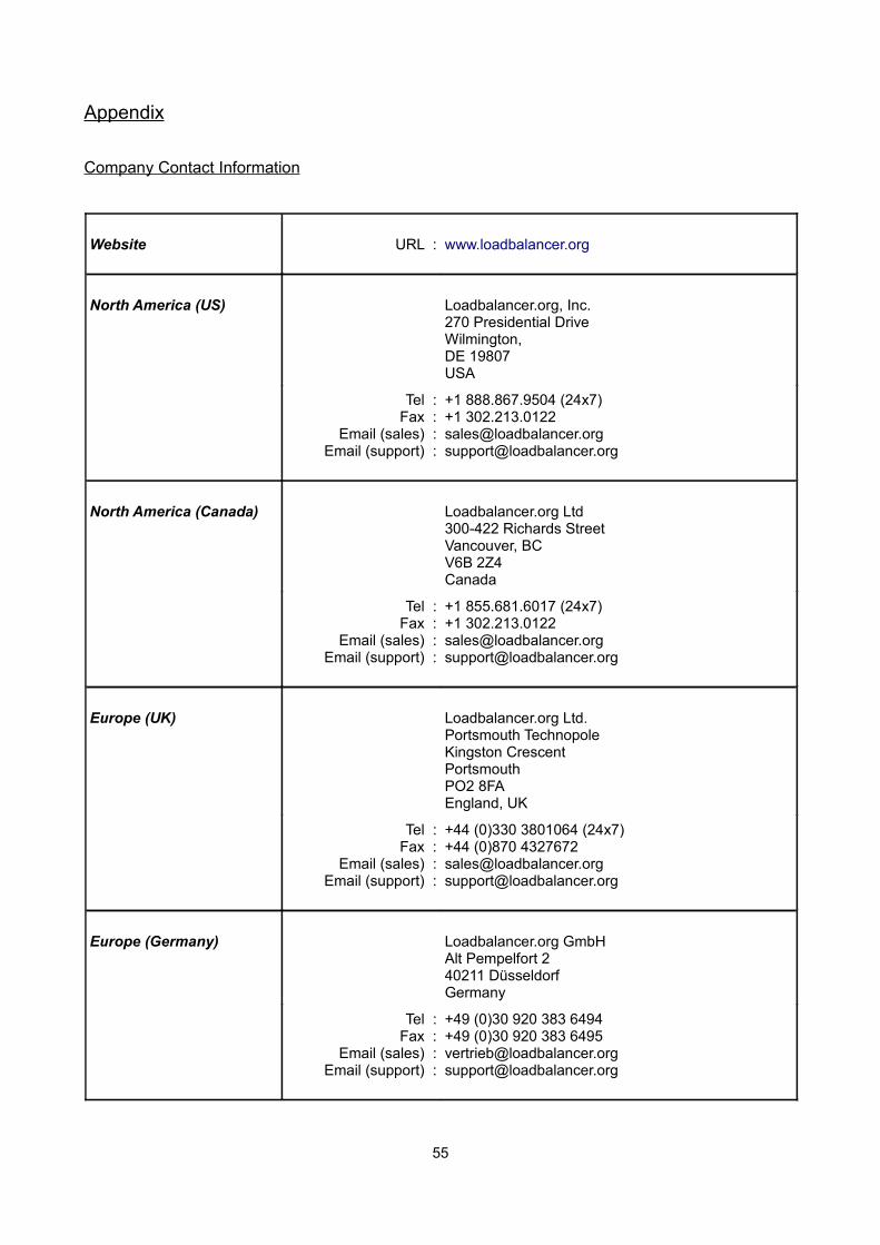
Appendix
Company Contact Information
Website URL : www.loadbalancer.org
North America (US) Loadbalancer.org, Inc.270 Presidential DriveWilmington,DE 19807USA
Tel :Fax :
Email (sales) :Email (support) :
+1 888.867.9504 (24x7) +1 [email protected]@loadbalancer.org
North America (Canada) Loadbalancer.org Ltd300-422 Richards StreetVancouver, BCV6B 2Z4Canada
Tel :Fax :
Email (sales) :Email (support) :
+1 855.681.6017 (24x7)+1 [email protected]@loadbalancer.org
Europe (UK) Loadbalancer.org Ltd.Portsmouth TechnopoleKingston CrescentPortsmouthPO2 8FAEngland, UK
Tel :Fax :
Email (sales) :Email (support) :
+44 (0)330 3801064 (24x7)+44 (0)870 [email protected]@loadbalancer.org
Europe (Germany) Loadbalancer.org GmbHAlt Pempelfort 240211 DüsseldorfGermany
Tel :Fax :
Email (sales) :Email (support) :
+49 (0)30 920 383 6494+49 (0)30 920 383 [email protected]@loadbalancer.org
55
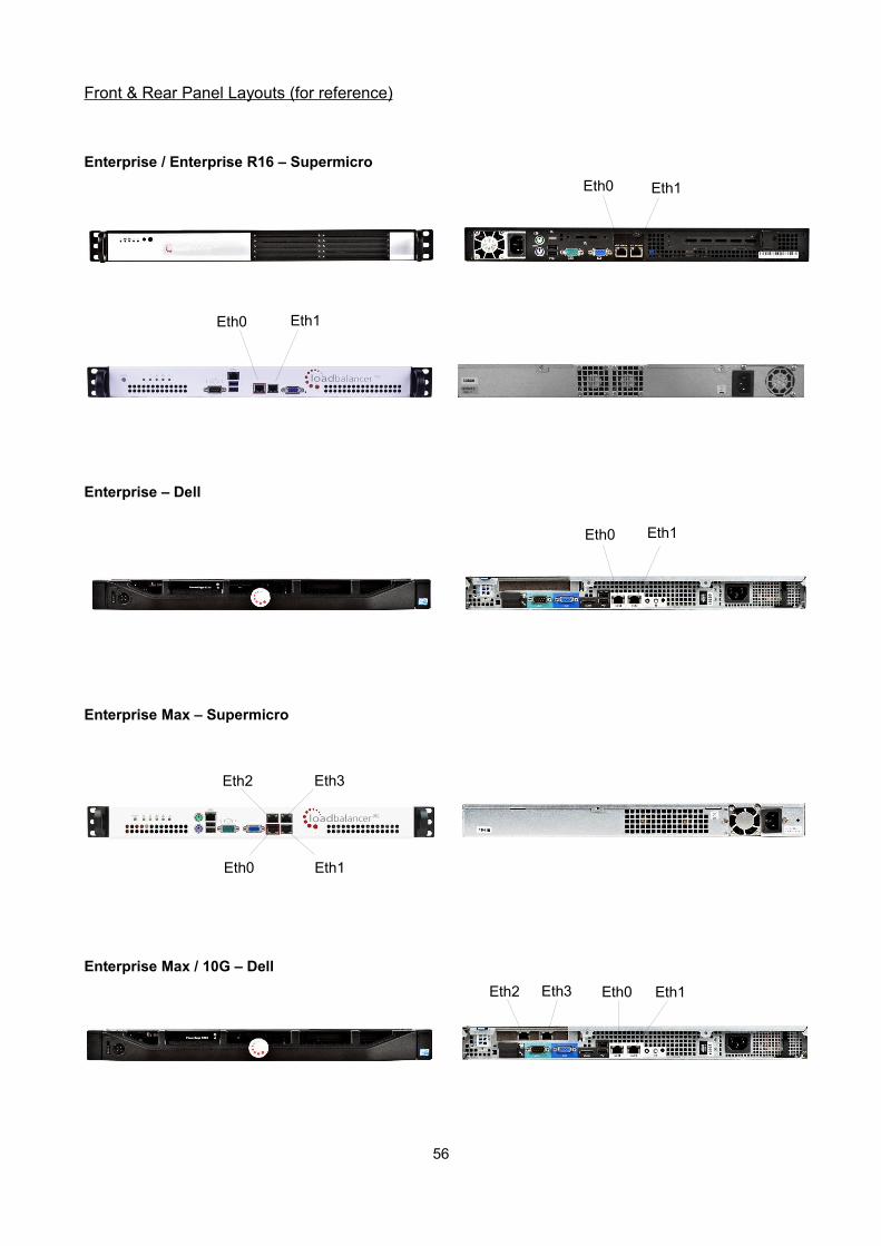
Front & Rear Panel Layouts (for reference)
Enterprise / Enterprise R16 – Supermicro
Enterprise – Dell
Enterprise Max – Supermicro
Enterprise Max / 10G – Dell
56
Eth0 Eth1
Eth2 Eth3
Eth2 Eth3 Eth0 Eth1
Eth0
Eth0 Eth1
Eth1
Eth0 Eth1