
Appendix G Haile Gold Mine EIS Monitoring and Management...
82
Appendix G Haile Gold Mine EIS Monitoring and Management Plan (MMP)
Transcript of Appendix G Haile Gold Mine EIS Monitoring and Management...

Appendix G
Haile Gold Mine EIS
Monitoring and Management Plan
(MMP)

This page is left blank intentionally.

Haile Gold Mine Monitoring and Management Plan
Haile Gold Mine, Inc.
Lancaster County, South Carolina
November 2013

ii
TABLE OF CONTENTS
1 Purpose and Objectives of Proposed Monitoring and Management at the Haile Gold Mine Site 1
1.1 Monitoring Plans and Permits 1
1.1.1 Existing Operations Manuals 2
1.1.2 Referenced, Expected Operations Manuals 2
1.1.3 Permits Available for Review 3
1.1.4 Permit Categories and Monitoring Requirements 4
1.2 Management Planning 4
2 Groundwater Monitoring 6
2.1 Monitoring Plans and Permits 6
2.1.1 Monitoring Program 6
2.1.2 Proposed Monitoring Program Protocols 6
2.1.3 Proposed Sampling Locations 7
2.1.4 Proposed Water Quality Chemical Analyte Monitoring List During Operations 9
2.1.5 Proposed Frequency of Sampling 12
2.2 Groundwater Level Monitoring 12
2.2.1 Monitoring of Groundwater Levels Surrounding Pit Activity 12
2.3 Water Supply Monitoring 12
2.3.1 Monitoring Private Wells Water Supply 12
2.3.2 Management of Private Wells Water Supply 13
2.4 Reporting and Management Planning 13
2.4.1 Federal and State Permit Reporting Requirements 13
2.4.2 Monitoring Reports 13
2.4.3 Management Planning 13
3 Surface Water Monitoring 14
3.1 Monitoring Plans and Permits 14
3.1.1 Monitoring Program 14
3.1.2 Proposed Surface Water Monitoring Program Protocols During Operations 15
3.1.3 Proposed Sampling Locations 16
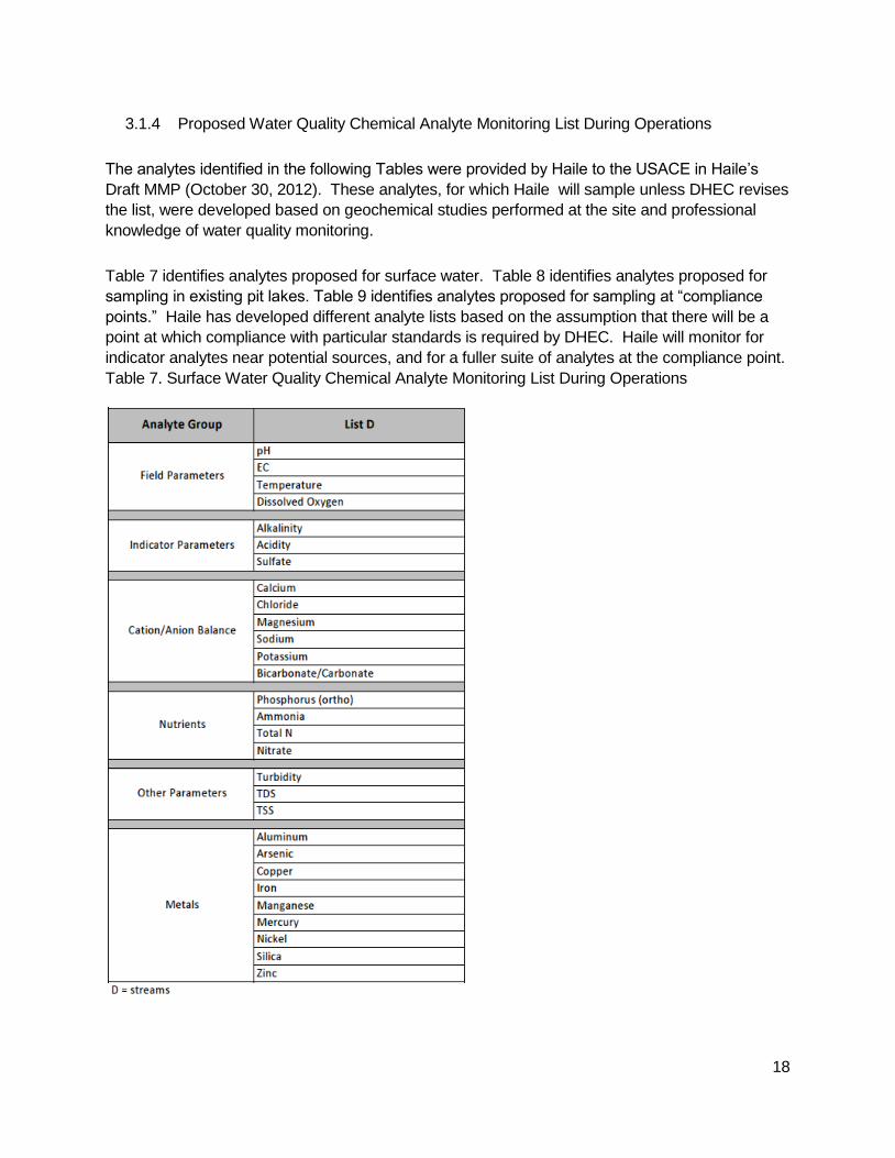
3.1.4 Proposed Water Quality Chemical Analyte Monitoring List During Operations 18
iii
3.1.5 Proposed Frequency of Sampling 21
3.2 Reporting and Management Planning 21
3.2.1 Federal and State Permit Reporting Requirements 21
3.2.2 Monitoring Reports 21
3.2.3 Management Planning 21
4 Wetlands Monitoring 22
4.1 Monitoring Plans and Permits 22
4.2 Wetland and Stream Buffers and Monitoring 22
4.3 Monitoring Program for Indirect Impacts 22
4.3.1 Proposed Monitoring Program Protocols 23
4.3.2 Proposed Monitoring Locations 25
4.3.3 Proposed Sampling Frequency 27
4.4 Reporting and Management Planning 27
4.4.1 Monitoring Reports 27
4.4.2 Management Planning 27
5 Wildlife Monitoring 28
5.1 Monitoring Plans and Permits 28
5.2 Reporting and Management Planning 28
5.2.1 Federal and State Permit Reporting Requirements 28
5.2.2 Monitoring Reports 28
5.2.3 Management Planning 28
6 Facilities Monitoring 33
6.1 Major Facilities Monitored During Operations 33
6.2 TSF 34
6.2.1 TSF Structural Monitoring 35
6.2.2 TSF Monitoring 35
6.2.3 TSF Underdrain Collection Pond 36
6.2.4 Emergency Operating Procedures 37
6.2.5 Reporting and Management Planning 37
6.3 Overburden Monitoring and Management Plan 39
6.3.1 Overburden Classification 39
iv
6.3.2 Overburden Testing 40
6.3.3 Overburden Management & Monitoring 41
6.4 Johnny’s Potentially Acid Generating OSA 43
6.4.1 Site Monitoring 43
6.4.2 Water Quality Monitoring 43
6.4.3 465 & 469 Collection Ponds 44
6.4.4 Reporting and Management Planning 44
6.5 Other Facilities 45
6.5.1 Contact Water Treatment Plant 45
6.5.2 Mill Site 47
6.5.3 Pipelines 54
6.5.4 Stormwater Facilities, Including Roadside Ditches 55
7 Reclamation Plan, Post-Mining Reclamation and Closure Monitoring 58
7.1 Site-Wide Reclamation Plan 58
7.2 Vegetation Plan 59
7.3 Post-Mining Land Use 60
7.4 Proposed Facilities 60
7.4.1 Backfilled Mine Pits 61
7.4.2 Pit Lakes 62
7.4.3 Johnny’s PAG 62
7.4.4 Green OSAs 64
7.4.5 Site Surface Water Management 64
7.4.6 Tailing Storage Facility 65
7.4.7 Borrow Areas 66
7.4.8 Ancillary Facilities 67
7.5 Post-Mining Reclamation and Closure Monitoring 67
7.6 Post-Mining Care and Maintenance 70
8 Cultural Resource Monitoring 71
8.1 Cultural Resources Management Plan 71
9 References 72

v
List of Tables
Table 1. State Permits & Monitoring Requirements 4
Table 2. Proposed Groundwater Monitoring Program Protocols During Operations 7
Table 3. Groundwater Wells Near TSF (Water Quality Chemical Analyte Monitoring List During Operations) 9
Table 4. All Other Groundwater Wells (Water Quality Chemical Analyte Monitoring List During Operations) 10
Table 5. Groundwater Compliance Point (Water Quality Chemical Analyte Monitoring List During Operations) 11
Table 6. Proposed Surface Water Monitoring Program Protocols During Operations 15
Table 7. Surface Water Quality Chemical Analyte Monitoring List During Operations 18
Table 8. Pit Lake Water Quality Chemical Analyte Monitoring List During Operations 19
Table 9. Surface Water Chemical Analyte Monitoring List at Expected Compliance Point 20
Table 10. Proposed Wetland Monitoring Protocol During Operations 24
Table 11. Overburden Classification at Haile Gold Mine 40
Table 12. Proposed Containment Systems for the Mill 50
Table 13. Proposed General Mining Schedule for Pit Development and Site Reclamation 69
List of Figures
Figure 1. Proposed Groundwater Quality Sampling Locations During Operations 8
Figure 2. Proposed Surface Water Quality Sampling Locations During Operations 17
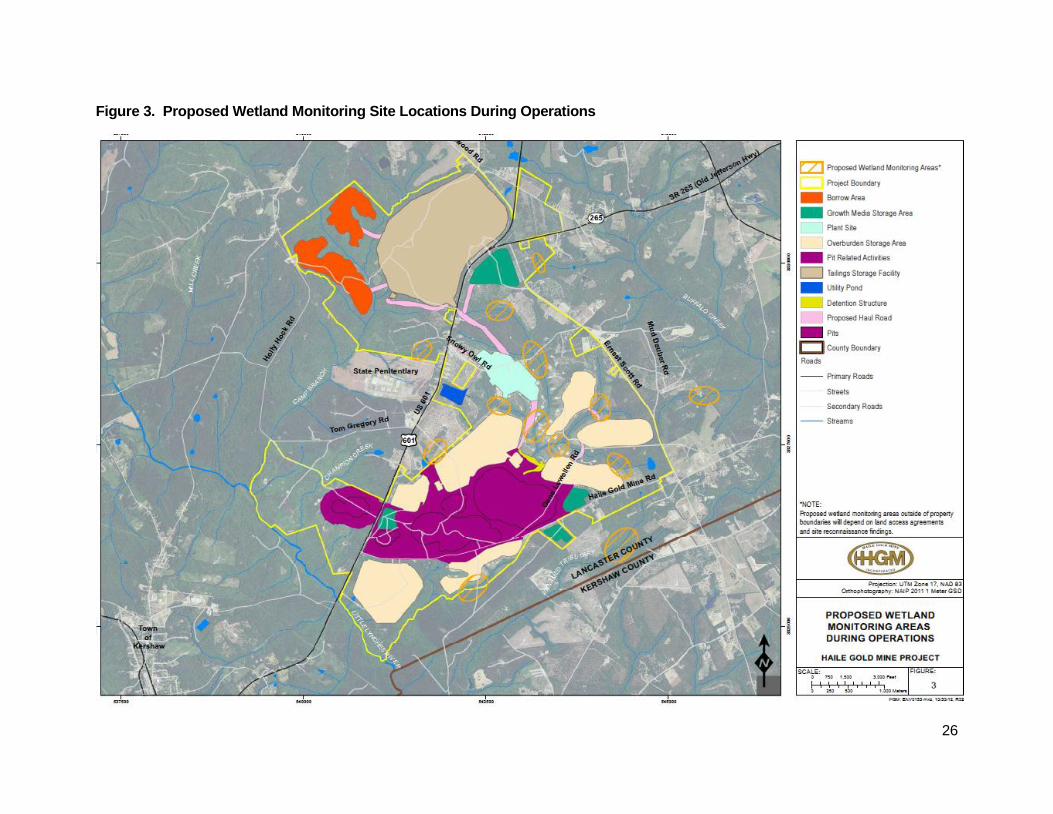
Figure 3. Proposed Wetland Monitoring Site Locations During Operations 26
Figure 4. General Mill Process Flow Sheet 49

vi
List of Acronyms and Abbreviations
ACHP – Advisory Council on Historic Preservation
AD – Acid Drainage
APP – Avian Protection Plan
CIL - Carbon-in-Leach
COC – Constituent of Concern
CWTP – Contact Water Treatment Plant
DHEC – South Carolina Department of Health and Environmental Control
EIS – Environmental Impact Statement
Haile – Haile Gold Mine, Inc.
HDPE – High-Density Polyethylene
HGMC – Haile Gold Mine Creek
LCRS – Leak Collection and Recovery System
MBTA – Migratory Bird Treaty Act
ML – Metal Leaching
MMP – Monitoring and Management Plan
MSDS – Material Safety Data Sheet
MSHA – Mine Safety and Health Act
NAG - Net Acid Generation
NCV - Net Carbonate Value
NEPA – National Environmental Policy Act

vii
NOI – Notice of Intent
Non-PAG – Non-Potentially Acid Generating
NPDES – National Pollutant Discharge Elimination System
NRHP – National Register of Historic Places
OSA – Overburden Storage Area
PAG – Potentially Acid Generating
PMP – Probable Maximum Precipitation Event
PPM – Parts Per Million
Project - Haile Gold Mine Project
SCDNR – South Carolina Department of Natural Resources
SHPO – State Historic Preservation Officer
SOP – Standard Operating Procedures
SPCC – Spill Prevention, Control and Countermeasures
THPO – Tribal Historic Preservation Officer
TSF – Tailing Storage Facility
USACE – United States Army Corps of Engineers
USFWS – United States Fish and Wildlife Service
VWP – Vibrating Wire Piezometer
WAD – Weak Acid Dissociable
WOUS – Waters of the United States

1
1 Purpose and Objectives of Proposed Monitoring and Management at the Haile Gold Mine Site
The purpose of this Proposed Monitoring and Management Plan (MMP) is to summarize the
monitoring and management activities that Haile has committed to perform as part of the Haile
Gold Mine Project (Project). If the South Carolina Department of Health and Environmental
Control (DHEC) issues State permits with alternate or contradictory terms or requirements to
Haile’s proposed MMP, the language of the permits will be controlling. However, Haile
anticipates that DHEC will incorporate the majority of Haile’s proposed monitoring and
management activities as described in this MMP.
Based upon discussions with the U.S. Army Corps of Engineers (USACE) Haile understands that
the USACE does not intend to include the terms of State permits as part of Haile’s Federal 404
permit. Rather, the information in this MMP will be used by the USACE primarily to describe the
Project for purposes of the Environmental Impact Statement (EIS).
This MMP is intended primarily to enable readers of the EIS to understand the monitoring that
Haile will perform for the Project.
The objectives of this MMP are to:
Identify the environmental media that Haile will monitor during the Project and provide
a summary of this monitoring;
Provide an overview of certain major operations and environmental media at the
Project site that Haile anticipates will be regulated by DHEC, as well as Haile’s
commitments for each;
Provide an overview of the major Project facilities to enhance understanding of how
Haile’s environmental monitoring and management activities will address any
potential environmental impacts of those facilities; and
Summarize certain additional information provided by Haile pursuant to the National
Environmental Policy Act (NEPA) process, relevant to monitoring and management
at the Project site.
1.1 Monitoring Plans and Permits
Monitoring programs play a key role in release prevention and identification, as well as providing a
basis for effective worker training. Monitoring is used to assure compliance with permit terms and
regulatory requirements. As explained more fully within this MMP, Haile has committed to
monitoring at intervals adequate to characterize the medium being monitored, as well as to
2
provide information in a timely manner to notify authorities and take any necessary corrective
actions.
1.1.1 Existing Operations Manuals
While most of Haile’s final operational plans are not yet completed, various reports or manuals
that include relevant monitoring or management information have been prepared. Manuals and
plans like these, prepared during Project planning, will be supplemented or replaced by the
operational plans (or manuals) prepared after permits are received to guide actual operations.
To minimize duplication of information and rationale for specific monitoring and sampling
requirements, this MMP relies upon and incorporates information from the following documents,
which are referenced in Sections as noted:
Wetland Monitoring Plan (ERC, February 2013). (See Section 4, Wetland Monitoring, for
further details regarding this plan.)
Wildlife Monitoring Program (Arcadis, 2013). (See Section 5, Wildlife Monitoring, for
further details regarding this plan.)
Tailing Storage Facility Operations, Inspection and Maintenance Manual (AMEC,
August 31, 2012). (See Section 6.2., TSF, for further details regarding this plan.)
Tailing Storage Facility Emergency Action Plan (AMEC, June 2013). (See Section 6.2.,
TSF, for further details regarding this plan.)
Overburden Management Plan (Schafer, November 2010). (See Section 6.3.,
Overburden Management Plan, for further details regarding this plan.)
Reclamation Plan (Date). (See Section 7, Reclamation Plan, for further details regarding
this plan.)
Cultural Resources Management Plan (Date). (See Section 8, Cultural Resources
Management Plan, for further details regarding this plan.)
1.1.2 Referenced, Expected Operations Manuals
In addition, Haile’s submissions to the agencies as part of the NEPA process have made
reference to compliance with certain other operational standards, with certain other operations
standards that, by virtue of the site activities, Haile knows it will develop. The EIS may contain
references to these standards that include information on environmental monitoring, management
and response to certain events, including:

3
Spill Prevention, Control and Countermeasures (SPCC) Plan – for petroleum products
at the Project;
Stormwater Pollution Prevention Plan (SWPPP) – for stormwater at the Project;
Overburden Material Testing Program – to assure that overburden is stored
commensurate with its acid generating potential;
Operational Water Quality Monitoring and Management Plan – which will provide
operational factors for monitoring surface and groundwater;
Operations Plans (for each major facility) – which will include environmental compliance
and monitoring obligations to be conducted by location;
Solid and Hazardous Waste Management Plan – for solid and hazardous waste at the
Project;
Post-Closure Water Quality Monitoring and Management Plan - which will include
environmental compliance and monitoring obligations for surface and groundwater.
1.1.3 Permits Available for Review
Final provisions regarding monitoring will be included in State permits. In some cases, these
permit terms are available for reference in this MMP. The following permits are referenced in this
MMP:
NPDES Individual Discharge Permit No. SC0040479, Outfalls 002 and 003 (October 7,
2013) (hereinafter NPDES Individual Permit)
NPDES General Stormwater Permit for Industrial Activity Permit No. SCR000000
(hereinafter NPDES Industrial General Permit)
NPDES General Permit for Stormwater Discharges Associated with Construction
Activities Permit No. SCR100000 (hereinafter NPDES Construction General Permit)
Air Construction Permit No. 1460-0070-CA (October 6, 2013)
Dam Safety Permit No. 29-0007 (October 7, 2013)

4
1.1.4 Permit Categories and Monitoring Requirements
The following table contains a list of the State permits that will apply to Haile Gold Mine
construction and operational activities, holding open columns where State permits have not yet
been issued.
Table 1. State Permits & Monitoring Requirements
Permit Monitoring Requirements
Air Permit (Construction) See Permit No. 1460-0070-CA (October 6, 2013)
Air Permit (Operations)
Dam Safety Permit See Permit No. 29-0007 (October 7, 2013)
Mining Permit (includes Reclamation Plan)
NPDES Individual Permit See Permit No. SC0040479 (October 7, 2013)
NPDES Industrial General Permit See Permit No. SCR000000
NPDES Construction General Permit See Permit No. SCR100000
CWTP Construction Permit
Surface Water Withdrawal Permit
1.2 Management Planning
This MMP focuses largely on Haile’s commitments for monitoring. Management for
environmental protection goes beyond monitoring, and includes both operational steps to remain
in compliance and procedures for addressing emergencies or other significant events. Haile will
develop the procedures to remain in compliance with permit terms; those procedures will be part
of the operational plans that implement the permits and will also provide for training for
employees.
In general, management of emergencies or significant events is addressed in permits, and
requires notification to the appropriate authorities. Upon notification, the authorities can evaluate
the situation, determine what information is needed, and work with Haile to develop and assure
implementation of the appropriate response. Because there may be many different

5
circumstances that are treated as “emergencies or significant events” under the permits, it is not
feasible to describe the reporting requirements or management planning for response in much
detail in this MMP.
Where appropriate, this MMP describes some of the measures in the Project design that are
intended to protect against adverse impact to environmental media. These include, but are not
limited to: double High-Density Polyethylene (HDPE) lined ponds, double contained pipelines,
lined storage facilities, closed-loop system for process water, concurrent reclamation, cyanide
destruct, and buffers for otherwise non-impacted wetlands and streams. However, complete
details on design of the Project to protect against and minimize potential environmental impacts
are not provided in this MMP.
6
2 Groundwater Monitoring
2.1 Monitoring Plans and Permits
Haile’s Operational Water Quality Monitoring Plan will provide for up-gradient and down-gradient
monitoring of the primary facilities at the Project site, but has not been drafted yet. Groundwater
monitoring associated with reclamation, closure and post-closure is addressed in Section 7. The
location and other details of groundwater modeling remain under development pending results of
hydrology analysis as well as the permitting process.
Monitoring and other provisions of NPDES permits, including Haile’s NPDES Individual Permit,
the NPDES Industrial General Permit, and the NPDES Construction General Permit are not
addressed in this section. Haile’s NPDES Individual Permit is addressed in Section 6.5.1, Contact
Water Treatment Plant. The NPDES Industrial General Permit and NPDES Construction General
Permit are addressed in Section 6.5.4, Stormwater Facilities.
2.1.1 Monitoring Program
Haile will monitor groundwater to comply with the requirements of its Mining Permit. The
groundwater monitoring is also planned to assemble data pertinent to evaluating potential indirect
impacts of Project activities.
Haile’s proposed groundwater monitoring program will enable verification that the extent of
predicted drawdown is occurring, and that, in the event drawdown extents differ from predicted,
adequate data will be available with which to update impact predictions. Primary determinants
of influence will be comparison to existing conditions, if available, and baseline data if existing
conditions are unavailable, as well as comparison to expected changes as predicted in the
model.
The groundwater monitoring program also identifies water quality analytes for which Haile will
monitor, unless DHEC revises Haile’s proposed analyte lists.
2.1.2 Proposed Monitoring Program Protocols
7
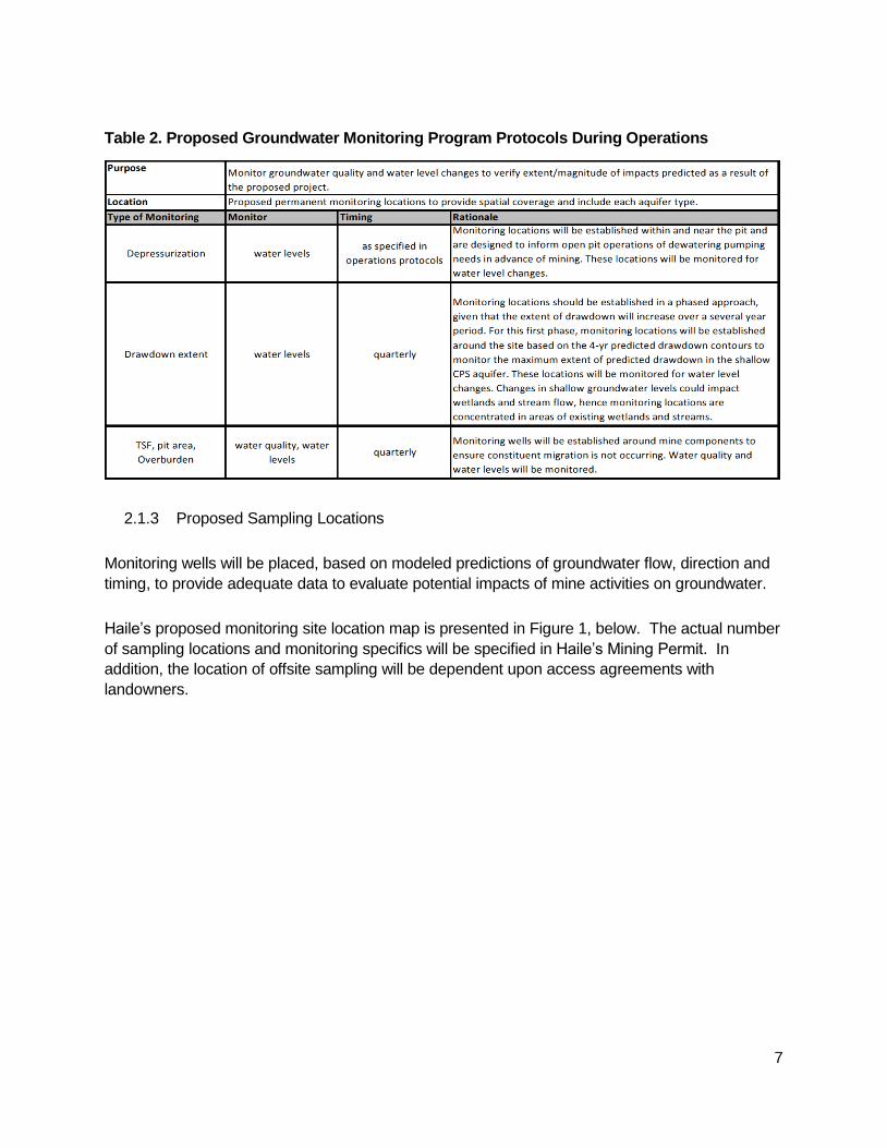
Table 2. Proposed Groundwater Monitoring Program Protocols During Operations
2.1.3 Proposed Sampling Locations
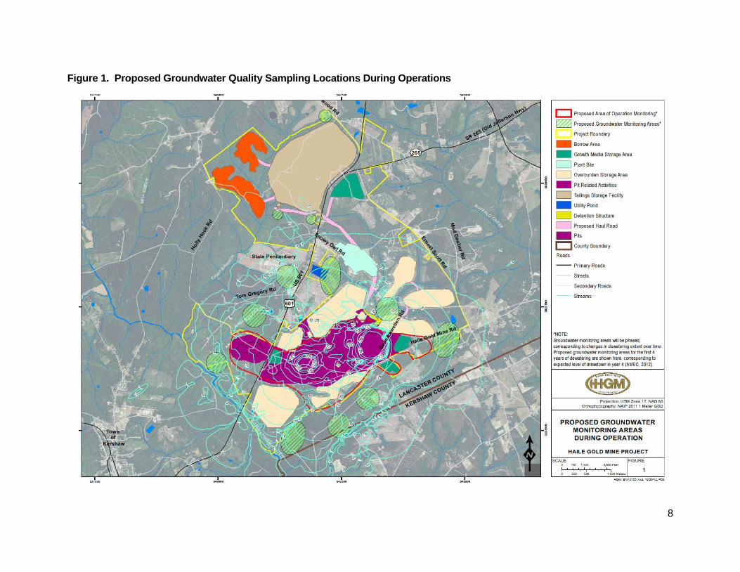
Monitoring wells will be placed, based on modeled predictions of groundwater flow, direction and
timing, to provide adequate data to evaluate potential impacts of mine activities on groundwater.
Haile’s proposed monitoring site location map is presented in Figure 1, below. The actual number
of sampling locations and monitoring specifics will be specified in Haile’s Mining Permit. In
addition, the location of offsite sampling will be dependent upon access agreements with
landowners.
8
Figure 1. Proposed Groundwater Quality Sampling Locations During Operations
9
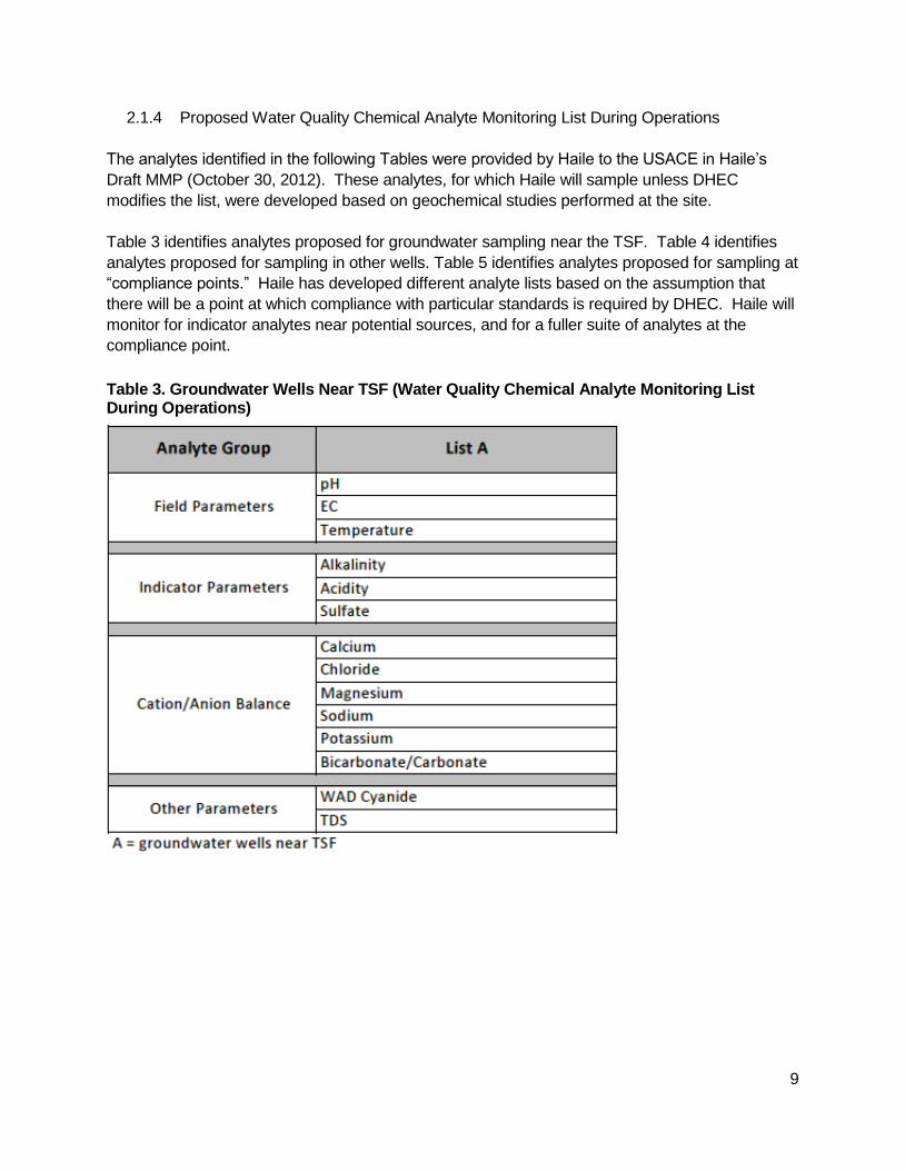
2.1.4 Proposed Water Quality Chemical Analyte Monitoring List During Operations
The analytes identified in the following Tables were provided by Haile to the USACE in Haile’s
Draft MMP (October 30, 2012). These analytes, for which Haile will sample unless DHEC
modifies the list, were developed based on geochemical studies performed at the site.
Table 3 identifies analytes proposed for groundwater sampling near the TSF. Table 4 identifies
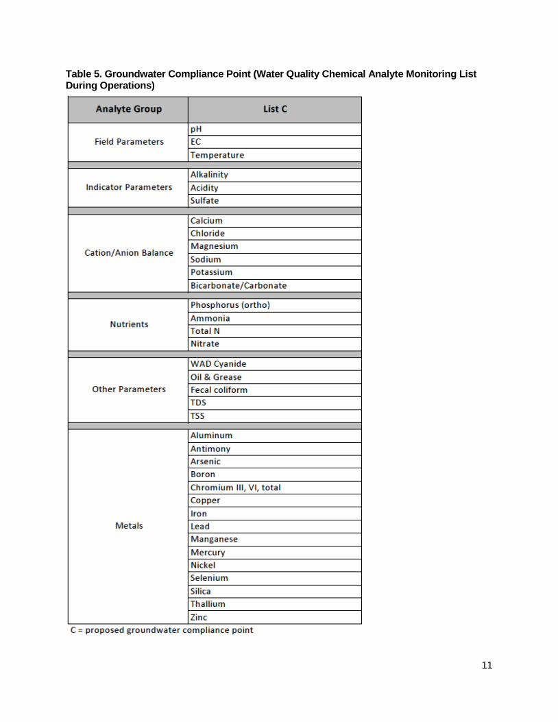
analytes proposed for sampling in other wells. Table 5 identifies analytes proposed for sampling at
“compliance points.” Haile has developed different analyte lists based on the assumption that
there will be a point at which compliance with particular standards is required by DHEC. Haile will
monitor for indicator analytes near potential sources, and for a fuller suite of analytes at the
compliance point.
Table 3. Groundwater Wells Near TSF (Water Quality Chemical Analyte Monitoring List During Operations)

10
Table 4. All Other Groundwater Wells (Water Quality Chemical Analyte Monitoring List During Operations)
11
Table 5. Groundwater Compliance Point (Water Quality Chemical Analyte Monitoring List During Operations)
12
2.1.5 Proposed Frequency of Sampling
Groundwater wells near the TSF will be sampled for water quality parameters quarterly.
All other groundwater wells will be sampled for water quality parameters quarterly.
Groundwater compliance points will be sampled for water quality parameters annually.
2.2 Groundwater Level Monitoring
2.2.1 Monitoring of Groundwater Levels Surrounding Pit Activity
The predicted drawdown of groundwater is likely to evolve as mining operations proceed. Due to
the changing nature of the groundwater drawdown over time, a phased groundwater monitoring
program will be implemented, whereby monitoring wells will be determined at optimum locations
corresponding to expected groundwater conditions between years 1 and 5. As operations
continue beyond this timeframe, new monitoring wells may be placed corresponding to the next
five or more years of groundwater monitoring; to determine optimum locations for years >5, the
groundwater monitoring data will be used to verify or update the groundwater contour conditions
that were predicted originally. Based upon this data analysis and conditions at the time, whether
additional groundwater wells are needed will be determined in consultation with DHEC.
Groundwater quality monitoring at the Project site will be identified in Haile’s Mining Permit and
operational aspects more fully described in Haile’s Operational Water Quality Monitoring Plan.
2.3 Water Supply Monitoring
The objective of the MMP regarding private wells and water supply is to identify potential impacts
to the availability of water in private wells in the vicinity of the mine site as a result of
depressurization activities at the Haile Gold Mine. If Haile is responsible for deprivation of water
supply, it will provide an alternate water supply or other appropriate relief to any affected
landowner(s). The goal of monitoring potential impacts to water supply is to provide timely
response to impacts for which Haile is responsible.
2.3.1 Monitoring Private Wells Water Supply
Haile will install a series of groundwater monitoring wells within the Project Boundary for
purposes, among others, of tracking the lateral and longitudinal movement of the groundwater as
it responds to Haile’s pumping of groundwater for pit depressurization purposes.
The monitoring system is intended to provide information on the impact of depressurization
activities on groundwater and surface water levels in wells, ponds, springs and streams. This
13
monitoring system will be used to anticipate adverse impacts on water sources and to direct the
remedial action that will be taken as a result of data obtained.
2.3.2 Management of Private Wells Water Supply
DHEC has indicated that management of private wells water supply impacted by mine-related
activities will be a condition of Haile’s Mining Permit. Thus, Haile expects that its Mining Permit
will include requirements to:
Establish a requirement to provide for independent, third party evaluation of potential
impacts to private wells and water supply, using the Water Resources Inventory (2013)
of all participating landowners;
Establish a third party independent investigation and review of complaints to determine if a
private party is adversely impacted by Haile’s pumping; and
Provide for appropriate remedial action and/or payment if adverse impacts are discovered to
have resulted from Haile’s pumping.
Haile also will investigate any complaints and work cooperatively with DHEC and the private party
to resolve any such complaints.
2.4 Reporting and Management Planning
2.4.1 Federal and State Permit Reporting Requirements
Haile will comply with the reporting requirements in its Mining Permit.
2.4.2 Monitoring Reports
Haile will submit annual ground water monitoring reports to DHEC.
2.4.3 Management Planning
In the event of sampling data (based on protocols and procedures to be established in
consultation with DHEC) requiring agency notification, DHEC, Mining Division will be notified and
consulted regarding further actions.
14
3 Surface Water Monitoring
The objective of the surface water monitoring is to insure that the Project is in compliance with
permit requirements, including the Mining Permit. Secondarily, the monitoring will provide early
warning of water impacts and a means of identifying contaminant sources to assist in identifying
contingency actions that will be employed. Surface water monitoring associated with reclamation,
closure and post closure is addressed in Section 7. In addition to other surface waters, this MMP
addresses monitoring of the existing pit lakes (Snake, Champion and Gault) during operations;
these pit lakes are currently governed by the on-going reclamation at the Project site. The
location and other details of surface water monitoring remain under development pending results
of hydrology analysis as well as the State permitting process.
Monitoring and other provisions of NPDES permits, including Haile’s NPDES Individual Permit,
the NPDES Industrial General Permit, and the NPDES Construction General Permit, are not
addressed in this section. Haile’s NPDES Individual Permit is addressed in Section 6.5.1, Contact
Water Treatment Plant. The NPDES Industrial General Permit and NPDES Construction General
Permit are addressed in Section 6.5.4, Stormwater Facilities.
3.1 Monitoring Plans and Permits
Surface water monitoring at the Project site will be identified in Haile’s Mining Permit and
operational aspects in Haile’s Operational Water Quality Monitoring Plan, which will include both
surface and groundwater.
3.1.1 Monitoring Program
Haile will monitor surface water to comply with the requirements of its DHEC Mining Permit. The
surface water monitoring will also assemble data pertinent to evaluating potential indirect impacts
of Project activities.

15
3.1.2 Proposed Surface Water Monitoring Program Protocols During Operations
Table 6. Proposed Surface Water Monitoring Program Protocols During Operations

16
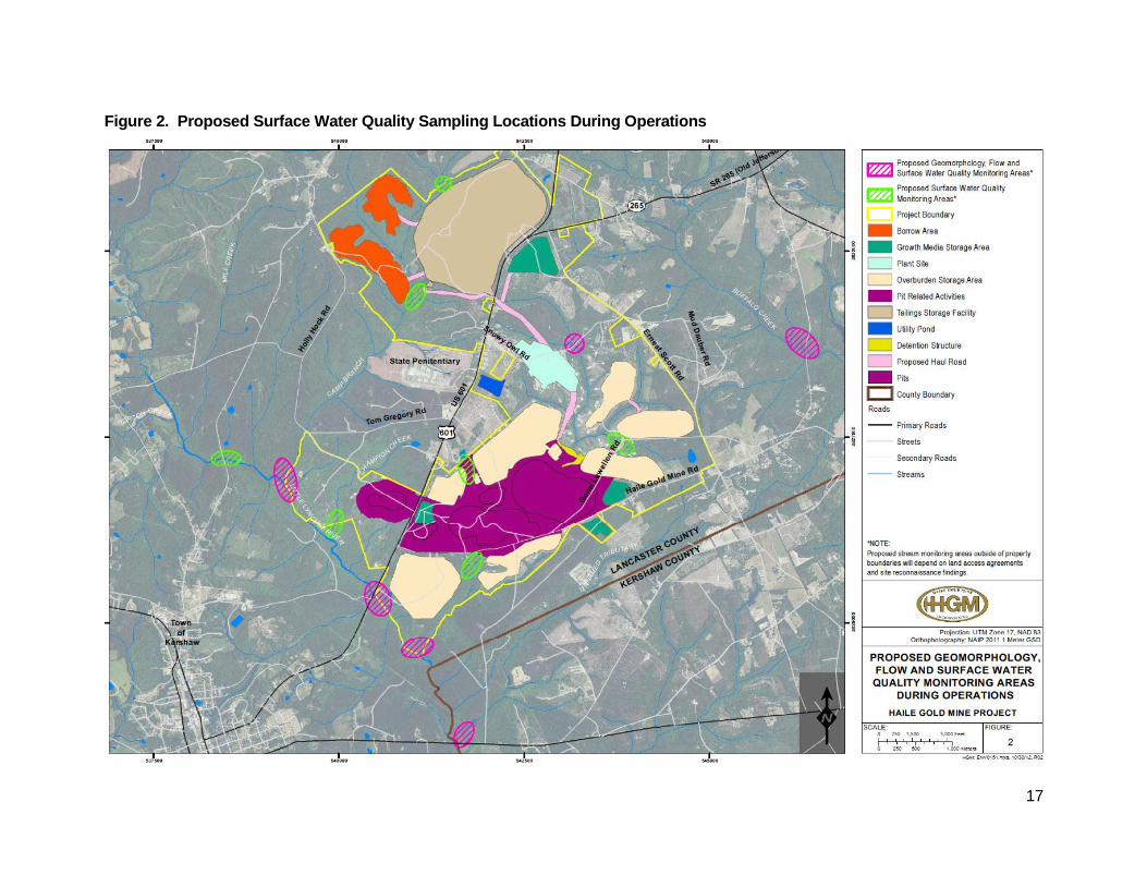
3.1.3 Proposed Sampling Locations
Haile’s proposed monitoring locations are located within drainages on the Project site and
surrounding areas and have been selected based upon location, physical stream characteristics,
site access, as well as those areas potentially influenced by the Project.
Haile’s proposed monitoring site location map is presented in Figure 2, below. The actual number
of sampling locations and monitoring specifics will be identified in Haile’s Mining Permit. In
addition, the location of offsite sampling will be dependent upon access agreements with
landowners.
17
Figure 2. Proposed Surface Water Quality Sampling Locations During Operations
18
3.1.4 Proposed Water Quality Chemical Analyte Monitoring List During Operations
The analytes identified in the following Tables were provided by Haile to the USACE in Haile’s
Draft MMP (October 30, 2012). These analytes, for which Haile will sample unless DHEC revises
the list, were developed based on geochemical studies performed at the site and professional
knowledge of water quality monitoring.
Table 7 identifies analytes proposed for surface water. Table 8 identifies analytes proposed for
sampling in existing pit lakes. Table 9 identifies analytes proposed for sampling at “compliance
points.” Haile has developed different analyte lists based on the assumption that there will be a
point at which compliance with particular standards is required by DHEC. Haile will monitor for
indicator analytes near potential sources, and for a fuller suite of analytes at the compliance point.
Table 7. Surface Water Quality Chemical Analyte Monitoring List During Operations

19
Table 8. Pit Lake Water Quality Chemical Analyte Monitoring List During Operations

20
Table 9. Surface Water Chemical Analyte Monitoring List at Expected Compliance Point
21
3.1.5 Proposed Frequency of Sampling
Streams will be sampled for water quality parameters quarterly.
Streams will be sampled for water flow hourly or quarterly, depending on the stream/sampling
location and methodology.
Existing pit lakes (Snake, Champion and Gault) will be sampled for water quality parameters
quarterly prior to dewatering.
Existing pit lakes (Snake, Champion and Gault) will be sampled for water level annually prior to
dewatering.
Surface Water Compliance Point will be sampled for water quality parameters annually.
3.2 Reporting and Management Planning
3.2.1 Federal and State Permit Reporting Requirements
Haile will comply with the requirements in its Mining Permit.
3.2.2 Monitoring Reports
Haile will submit annual surface water monitoring reports to DHEC.
3.2.3 Management Planning
In the event of sampling data (based on protocols and procedures to be established in
consultation with DHEC) requiring agency notification, DHEC, Mining Division will be notified and
consulted regarding further actions.

22
4 Wetlands Monitoring1
The objective of Haile’s wetlands monitoring is to detect potential alterations of wetland
characteristics resulting from site activities over the life of the Project. The wetland monitoring
program will generate information related to indirect effects to otherwise non-impacted Waters of
the United States (WOUS) that may occur as a result of the Project.
4.1 Monitoring Plans and Permits
Haile has developed a program for wetlands monitoring at and near the Project site. Haile has
proposed a Revised Mitigation Plan (July 2013) that provides compensatory mitigation for direct
and indirect impacts to wetlands and streams. Because of this, monitoring for indirect impacts to
wetlands and streams would be voluntary, since for all intents and purposes the indirect impacts
of the Project have been accounted for in the Revised Mitigation Plan (July 2013).
4.2 Wetland and Stream Buffers and Monitoring
Haile will maintain a vegetated buffer of 50 feet between its activities and wetlands and streams
that are not permitted for direct impact. Haile expects that its Section 404 permit will identify this
buffer as part of the Project, but will not specify routine monitoring or reporting regarding the buffer
area.
Haile expects to mark the buffer areas (e.g., through posting of signs) and identify the buffer areas
as “no disturbance” on maps used during construction and operations. Employees will be trained
to keep equipment and materials out of the buffer areas. Haile will monitor the buffers through
management of its construction and mining activities.
4.3 Monitoring Program for Indirect Impacts
The Wetlands Monitoring Program will record and quantitatively describe characteristic wetland
parameters over the short‐ and long‐term. Monitoring of wetlands within the Project site and
surrounding the site will collect data from the wetlands that could reflect potential indirect impacts
that may occur, including the dominant vegetation communities within those wetlands, the typical
hydrology and soil conditions for those wetlands, and the natural changes that may occur to those
wetlands over time.
1 More information regarding proposed wetlands monitoring at the Haile site can be found in
ERC’s Wetland Monitoring Plan (February 2013).

23
4.3.1 Proposed Monitoring Program Protocols
Table 10 identifies the Proposed Wetland Monitoring Protocol During Operations.

24
Table 10. Proposed Wetland Monitoring Protocol During Operations

25
4.3.2 Proposed Monitoring Locations
Haile has identified potential monitoring locations, on and off-site. Figure 3 identifies 13 locations,
but Haile expects that approximately 10 of the 13 will be selected for monitoring. For off-site
locations, the ability to monitor will depend on obtaining site access to property owned by others.
The suggested monitoring locations have been selected based upon location, physical wetland
characteristics, site access, as well as those areas potentially influenced by the Project.
The map showing the 13 potential monitoring locations (from which approximately 10 will be
selected) is presented in Figure 3, below.
26
Figure 3. Proposed Wetland Monitoring Site Locations During Operations

27
4.3.3 Proposed Sampling Frequency
Haile will conduct sampling as follows:
Vegetation parameters will be sampled annually.
Soil parameters will be sampled annually.
Water parameters will be sampled annually, with the exception of the vibrating wire
piezometer (VWP), which will be sampled continuously (hourly or daily, depending on
methodology).
Haile will develop a wetland monitoring operations manual to address detailed aspects, such as
methodologies, monitoring layouts, device establishment, sampling protocols, time constraints,
data collection and recording methods, and reporting formats.
4.4 Reporting and Management Planning
Haile’s Revised Mitigation Plan (July 2013) provides compensatory mitigation for potential indirect
impacts to wetlands on and near site that may be impacted by the Project. For that reason, Haile
does not expect that the monitoring of wetlands for indirect impacts will be a permit requirement.
4.4.1 Monitoring Reports
Haile anticipates preparing an annual report on wetland monitoring data and providing that report
to DHEC and the USACE. The annual report will provide summary background information on
the monitoring project including methods, monitoring site characteristics, and relevant mapping.
The results of the monitoring will be presented in data tables designed to facilitate comparison
between monitoring sites and against previous years within each monitoring site. Changes in
monitoring measurements that are determined to be statistically different from the previous year’s
measurements will be reported and analyzed. In addition to presenting the quantitative data from
each monitoring location, general information regarding significant on‐site and off‐site
development, abnormal climatic events, and deviations from the monitoring protocol with potential
to affect data quality will be reported.
4.4.2 Management Planning
Haile intends to implement this wetland monitoring program and collect information. Haile will
confer with the USACE and DHEC about any further monitoring and data collection.
28
5 Wildlife Monitoring
The objective of Haile’s Wildlife Monitoring Program is to insure compliance with federal laws
protecting avian species, and to keep records of mortalities to help pinpoint the locations of
mortalities and the extent to which they are occurring.
5.1 Monitoring Plans and Permits
Wildlife monitoring at Haile will also be described in Haile’s standard operating procedures for the
site.
5.2 Reporting and Management Planning
5.2.1 Federal and State Permit Reporting Requirements
Haile does not anticipate any Federal or State permit reporting requirements with respect to
wildlife monitoring, but may have certain management obligations.
5.2.2 Monitoring Reports
Haile does not anticipate any monitoring report requirement with respect to wildlife monitoring.
5.2.3 Management Planning
The following management measures are planned for avian and terrestrial wildlife during all
phases of the mine life:
5.2.3.1 General Management Practices for Birds
Following Migratory Bird Treaty Act (MBTA) terms described in 16 U.S.C. 703 (a), Haile cannot
pursue, hunt, capture, collect, kill or sell/barter any bird or bird part, or any nest, egg or any
product of bird covered under the MBTA. Haile will adhere to these terms.
If injured or trapped bird protected under MBTA is observed, Haile will notify the U.S. Fish and
Wildlife Service (USFWS) and the South Carolina Department of Natural Resources (SCDNR).
Contact information is:
US Fish and Wildlife Office: (843) 727-4707
SCDNR, Nuisance Wildlife Division, Region 2
295 S. Evander Drive, Florence, SC 29506

29
Wildlife 843-661-4766
Fisheries 843-661-4767
Law Enforcement 843-661-4766
If bird mortalities occur at the site, Haile will keep records of the mortalities to help pinpoint the
locations of mortalities and the extent to which they are occurring.
5.2.3.2 General Management Practices for Raptors
The Bald and Golden Eagle Protection Act is a federal law that protects bald and golden eagles
from harmful impacts and actions. In 2007, the USFWS developed The National Bald Eagle
Management Guidelines to advise landowners and land managers who share land with bald
eagles when and under what circumstances the protective provisions of the Eagle Act may apply
to their activities (USFWS 2007). These management guidelines are followed by the SCDNR for
bald and golden eagles year round. Permits can be obtained under this law, but Haile will adhere
to The National Bald Eagle Management Guidelines provided by the USFWS in May of 2007
(USFWS 2007) which obviates the need for a permit. No bald or golden eagles or their nests were
identified during wildlife surveys at and near the Haile Project location. If such species or their
nests are identified, Haile will work with the SCDNR and USFWS to determine the appropriate
actions. Depending upon the circumstances (e.g., whether bald or golden eagles commence
nesting activities at or near the Project during mining activities rather than in advance of Project
activities), the response may differ.
If other active raptor nests are identified during the breeding season (generally April through
August), Haile will work with the SCDNR and USFWS to determine the appropriate actions.
Depending upon the circumstances (e.g., whether the raptors commence nesting activities at or
near the Project during mining activities rather than in advance of Project activities), the response
may differ.
Haile will not intentionally feed any raptors.
If other active raptor nests are identified during the breeding season (generally April through
August), Haile will keep a distance between the activity and active nest (i.e., establish a ‘buffer’).
An active nest is defined as any nest that is frequented or occupied by a raptor (nestling,
fledgling or adult) during the breeding season. The buffer areas serve to minimize visual and
auditory impacts associated with human activities near nest sites. Buffers and activities for other
raptors will be established in consultation with the USFWS and SCDNR.
30
5.2.3.3 General Management Practices for Terrestrial Mammals
Haile will fence all HDPE-lined ponds and TSF perimeter with an eight-foot tall fence and the
Project boundary will be fenced where practicable, which will help deter terrestrial mammal
entry.
All fencing around HDPE-lined ponds and TSF perimeter will be inspected regularly by Haile
personnel, or designee, performing their job functions.
Transportation corridors on site will be periodically visually surveyed for signs of wildlife.
Haile will use skirting to enclose open spaces as necessary beneath raised structures, such as
buildings, to deter wildlife from denning, resting or hiding.
Wildlife will not intentionally be fed, harassed or approached.
Vehicle traffic will follow posted speed limits to prevent accidents with wildlife.
5.2.3.4 Management Practices for Open Solution Ponds, including the TSF
As noted above, fencing will be installed around HDPE-lined ponds and the TSF to restrict entry
and the property will be fenced, where practicable, for security, which will deter some wildlife
entry. Note also that these management practices are consistent with the International Cyanide
Management Code (ICMC 2012) procedures for wildlife for tailings impoundments.
TSF management will be consistent with the principles and safe practices as described in the
International Cyanide Management Code for protection of birds and other wildlife from adverse
effects of cyanide process solution. This includes the following measures:
Where birds or other wildlife have access to water impounded in the TSF, operations will
implement measures to limit the concentration of WAD cyanide in the TSF to a
maximum of 50 ppm.
For managed pond systems, as often as possible, uneven water margins and dam floors
that may form islands will be avoided, as these can attract birds.
Contact and process water ponds will be designed and operated in such a way as to
restrict access where necessary and to provide a means of escape for trapped animals
(textured exit ramps, etc.). It may be possible in some cases to safely rescue wildlife if
discovered quickly enough.
Vegetation surrounding the perimeter of ponds will be cleared, and infrastructure around
open solution ponds and the TSF will be minimized where practicable.

31
As part of the closure of all operations, the steps necessary to decommission mine facilities will
be determined so that the facility can be closed in a manner that prevents adverse impacts to
people, wildlife or the environment. The perimeter fence around HDPE-lined ponds and the TSF
will remain in place for safety (and wildlife deterrence) during reclamation. Reclamation
management is addressed further in Section 7.
Wildlife monitoring will be implemented at all open retention structures that are HDPE-lined. For
these structures, Haile staff will visually inspect each structure and, if wildlife is observed, they
will try to deter the wildlife away from the structures. Measures to deter wildlife will include, but
not be limited to the following: clapping, honking vehicle horn, air horn, more aggressive
mechanical noises or pyrotechnics (bangers/screamers/lighting), or other types of non-
threatening noise making devices.
5.2.3.5 Management Practices for Transmission Lines
The design of substations and distribution and transmission lines for Haile Gold Mine will follow
the guidelines established in the Rural Utilities Service (RUS) Substation Design and
Transmission Line Design Handbooks. Haile will design and construct its transmission lines to
meet these requirements, and will follow the guidelines in the Suggested Practices for Avian
Protection on Power Lines - The State of the Art in 2006 (APLIC 2006) for the protection of
federally and state protected avian species from electrocution and line strikes. Below are the
best management practices and avian protection plan that Haile will implement specific to
transmission lines on the property owned or managed by Haile.
5.2.3.5.1 Best Management Practices
Isolation will be provided when possible. Isolation refers to a minimum separation of 150 cm (60
in) between phase conductors or a phase conductor and grounded hardware/conductor.
Insulation, which refers to cover phases or grounds where adequate separation is not feasible,
will be considered when attempting to make a structure safe for avians. Examples of coverings
are: phase covers, bushing covers, arrester covers, cutout covers, jumper wire hoses, and
covered conductors.
Perch discouragers will be used to deter birds from landing on hazardous (to birds) pole
locations where isolation, covers, or other insulating techniques cannot be used.
Priority will be given to poles preferred by raptors or other birds that have a high electrocution
risk.
5.2.3.5.2 Avian Protection Plan for Transmission Lines
The following Avian Protection Plan (APP) will be implemented at the Haile Mine site for
transmission lines.
32
5.2.3.5.2.1 Training
Haile will provide avian issues training to all appropriate personnel. The training will encompass:
the reasons, needs, and methods for reporting avian mortalities; following nest management
protocols; disposing of carcasses; complying with applicable regulations; and, understanding
the potential consequences of non-compliance.
Supplemental training will be provided when there are changes in regulations, permit conditions,
or internal policies.
5.2.3.5.2.2 Construction Design Standards
Haile will include, at a minimum, the accepted standards for both new construction and
retrofitting techniques as recommended in APLIC (2006) to limit avian interactions when
designing and siting new facilities and operating and maintaining existing facilities.
5.2.3.5.2.3 Nest Management
Haile will develop, in consultation with the SCDNR and USFWS, specific procedures for
managing nests of protected species on utility structures, including a process for problem nests
that need to be relocated or removed. These procedures will be discussed during training to
ensure consistent treatment of avian nest issues and compliance with regulations or permits
related to nest management.
5.2.3.5.2.4 Mortality Reduction Measures
Haile will implement the general management practices for birds described above.
Haile will implement the avian mortality reporting system as described in above.
5.2.3.5.2.5 Quality Control
Haile will review existing APP practices and ensure their efficiency and effectiveness, and
update procedures and standards as needed.
33
6 Facilities Monitoring
6.1 Major Facilities Monitored During Operations
This part of the MMP has been included so that the reviewer can understand how the monitoring
described above relates to the major site facilities during operations, including the following:
Tailing Storage Facility. See Section 6.2.
TSF Impoundment. See Section 6.2.1.
TSF Underdrain Collection Pond. See Section 6.2.3.
Green OSAs (Ramona, Robert, Hayworth, Hilltop, James and 601). See Section 6.3
Johnny’s Potentially Acid Generating (PAG) OSA, including the 465 and 469 Collection
Ponds. See Section 6.4.
Other Facilities
Contact Water Treatment Plant, including the 19 Pond. See Section 6.5.1
Mill Site, including the Process Event Pond. See Section 6.5.2
Pipelines. See Section 6.5.3
Stormwater management facilities, including roadside ditches. See Section 6.5.4

34
6.2 TSF2
Initial, normal, and emergency operating procedures for the TSF are described in the TSF
Operation, Maintenance and Inspection Manual (August 31, 2012). A contingency plan for
emergency conditions and a discussion of safety measures and techniques for periodic
monitoring are also provided therein.
As part of the requirements for Haile’s Dam Safety Permit No. 29-0007, a comprehensive
Emergency Action Plan (June 2013) has also been developed. The goal of an emergency
preparedness plan is a written procedure for reacting to emergency situations caused by a
threat of the TSF embankment failure.
The TSF is designed to receive and store tailing from the Mill processing plant, arriving in a slurry.
The TSF will be operated to separate the liquid and the solids so that the liquid can be recycled for
use in the Mill, and the solids can settle and eventually dewater, starting during operations and
completing the process after closure. Tailing will retain residual Sodium Cyanide solutions at
projected concentrations of less than 50 ppm Weak Acid Dissociable (WAD) Cyanide. The
ultimate TSF would be constructed in four stages with storage to contain the current life-of-mine
total tons of tailing. All four stages allow for the storage of an operating Reclaim Pond and the
Probable Maximum Precipitation (PMP) event with four (4) feet of freeboard above the maximum
water elevation.3
The TSF will be monitored for structural integrity and for possible releases of pollutants into the
environment, in accordance with its Dam Safety Permit No. 29-0007 and/or Mining Permit, as
summarized herein. Final permit terms and conditions of Haile’s Mining Permit have yet to be
established by DHEC.
For reclamation activities associated with the TSF, see Section 7.
2 See Dam Safety Permit No. 29-0007; Haile, Draft Project Description (submitted February 22,
2013 ); TSF Operation, Maintenance and Inspection Manual (August 31, 2012); and, TSF
Emergency Action Plan (June 2013) for additional information on the TSF.
3 A PMP event is defined by the American Meteorological Society as “the theoretically greatest
depth of precipitation for a given duration that is physically possible over a particular drainage
basin at a particular time of year” (AMS, 1959). The PMP storm for the Haile Gold Mine site is
calculated as 47.96 inches for a 72-hour event. Freeboard is a function of the facility design and is
calculated in order to provide a factor of safety greater than that for which the facility is designed.

35
6.2.1 TSF Structural Monitoring
6.2.1.1 TSF Geotechnical Measurements and Structural Integrity
Structural Integrity of the TSF will be monitored in accordance with the terms of Haile’s Dam
Safety Permit No. 29-0007. Monitoring for TSF stability will include visual monitoring as well as
geotechnical instrumentation that will be installed in and around the TSF. Monitoring
instruments include vibrating wire piezometers (VWPs), monuments to measure embankment
settlement and movement, and monitoring of groundwater for possible leaks from the TSF.
Groundwater quality monitoring is addressed more fully in Section 2, Groundwater.
6.2.2 TSF Monitoring
The TSF and the Mill processing facility provide for a “closed loop” system in which there is no
discharge of TSF fluids or materials into surface waters. In accordance with Haile’s Mining
Permit, Haile anticipates that surface water and groundwater in the vicinity of the TSF will be
monitored in order to detect and respond to a release from the tailing and solution stored within
the TSF.
Shallow groundwater will be routed under the TSF in collection pipes installed below the HDPE
and low-permeability soil liner to route groundwater from beneath the facility (to avoid contact with
the tailing material). Initially, per DHEC’s request, this shallow groundwater will be sampled at a
manhole access point and may be pumped to the TSF Underdrain Collection Pond where it would
be pumped back into the TSF Reclaim Pond for return to the Mill for reuse as process water.
The earthfill material used for the TSF embankment is site material classified as “Green” (see
Section 6.3, Overburden Monitoring and Management Plan) or other clean material. Runoff
from the TSF embankment will be monitored in accordance with the requirements of the Industrial
General Stormwater Permit No. SCR000000.
The TSF will have a stormwater management and collection system for non-process water,
meaning run off that does not come into contact with the tailing or tailing pond. Stormwater at
the Haile Gold Mine will be managed in accordance with the Industrial General Stormwater
Permit No. SCR000000. Consequently, water will be released to receiving water without chemical
treatment after suspended solids have been removed in sediment ponds. Stormwater
management and monitoring is described in Section 6.5.4.
6.2.2.1 Surface Water Monitoring
In accordance with Haile’s Mining Permit, Haile anticipates that surface water above and below
the TSF will be monitored. See Section 3 for more details on Surface Water Monitoring at the
Haile site. This monitoring will serve to detect releases from the tailing and solution stored
within the facility. In the event of sampling data indicative (based on protocols and procedures to
be established in consultation with DHEC) of a release from the tailing or solution material, the

36
Management Procedures identified in Section 3.2.3 (surface water) and any applicable Reporting
Procedures in Haile’s State permit(s) will be followed.
6.2.2.2 Groundwater Quality Monitoring
In accordance with Haile’s Mining Permit, Haile will conduct monitoring of groundwater.
Groundwater monitoring is described in Section 2. This monitoring will serve to detect releases
from the tailing and solution stored within the facility. In the event of sampling data indicative
(based on protocols and procedures to be established in consultation with DHEC) of a release
from the tailing or solution material, the Management Procedures identified in Section 2.4.3
(groundwater) and any applicable Reporting Procedures in Haile’s State permit(s) will be followed.
At the TSF, Haile expects that groundwater wells will be installed at the locations identified in
Section 2.1.3, including “upstream” of the TSF and “downstream” of the TSF. Sampling and
characterization of samples from groundwater quality monitoring wells and groundwater
manhole sumps will be conducted in accordance with DHEC permit requirements.
6.2.2.3 Tailing Materials and Process Water
6.2.2.3.1 Cyanide Management
Cyanide will be present only in the “closed-loop” process water used at the Mill and circulated
through the TSF. Under normal operating conditions, flow from the Mill will be pumped to the TSF.
The pipelines from the Mill to the TSF will be double-contained (either one pipe inside another
pipe, or a pipe in a lined ditch). See Section 6.5.3, for further details on pipeline management. If
the cyanide level is greater than or equal to 50 ppm WAD cyanide, the flow would be directed to
the cyanide destruction tanks, where cyanide levels would be reduced using a sulfur dioxide and
air process. In the TSF, UV sunlight and air would naturally decompose cyanide and cyanide
complexes to further decrease cyanide levels.
Haile will operate the gold extraction process at the Mill consistent with the International
Cyanide Management Code so that the cyanide level (measured as weak acid dissociable
cyanide, CNwad) in the TSF will be less than 50 ppm CNwad. In accordance with its Mining Permit,
Haile anticipates that CNwad levels will be tested at the Reclaim Pond in the TSF.
6.2.3 TSF Underdrain Collection Pond
The TSF is designed with an underdrain collection system placed below the tailing (but above
the HDPE liner) that collects seepage of fluids and places them in the double HDPE-lined
Underdrain Collection Pond. Fluids from this Underdrain Collection Pond are pumped back into
the TSF Reclaim Pond and used during operations as process water in the closed-loop
recycling system between the Mill and the TSF.

37
In accordance with the TSF Operation, Maintenance and Inspection Manual, Haile will undertake
periodic visual monitoring and management actions related to the Underdrain Collection Pond,
including the Leakage Collection and Recovery Systems (LCRS) and underdrain collection sump
pumps, for purposes of prevention, identification, and appropriate response in the event that
leakage should develop through the primary HDPE liner in the Underdrain Collection Pond.
6.2.3.1 Leak Collection and Recovery System
All of the double-HDPE lined ponds at the Project site will have a similar Leak Collection and
Recovery System (LCRS). It is described more fully here, but see also Sections 6.4.3 (465 and
469 Collection Ponds) and 6.5.1.2 (19 Pond).
The LCRS will be constructed as part of the Underdrain Collection Pond. The purpose of the
LCRS is to provide a method to collect fluids in the event of a leak in the primary HDPE liner.
Leakage will be collected and removed from a low point located above the secondary HDPE liner.
6.2.3.1.1 LCRS – Monitoring and Response
Leakage through the primary HDPE liner of the Underdrain Collection Pond will be indicated by
the presence of process water in an LCRS sump. Level probes in the sump will start and stop
the LCRS sump pump automatically. A totalizing flow meter on the discharge of the pump
provides local indication of total flow.
Upon detection of leakage, pond levels will be reduced and an investigation conducted to
determine the cause and location of the leakage.
6.2.4 Emergency Operating Procedures
Potential consequences of emergency situations and unforeseen natural disasters are
addressed in Section 3.3. of the TSF Operation, Maintenance and Inspection Manual (August 31,
2013) and the Duckwood Tailing Storage Facility Emergency Action Plan (June 2013).
Contingency procedures are described to reduce the effects of possible loss of tailing material
and process water from the containment facilities.
6.2.5 Reporting and Management Planning
6.2.5.1 Federal and State Permit Reporting Requirements
Haile will comply with the reporting requirements in its Mining Permit. For further information on
Haile’s reporting with respect to surface and groundwater sampling data, see Section 2.4.3 and
3.2.3, respectively.
38
Haile expects that its Mining Permit will require regular reporting of the results of monitoring at
the TSF. Haile also expects that this permit will require notification and reporting to DHEC if
monitoring indicates a serious matter of structural integrity of the TSF or an actual or potential
release of tailing or solution into the environment.
6.2.5.2 Management Planning
Haile will develop operational and management plans to ensure compliance with permit terms,
including any emergency reporting and responses.

39
6.3 Overburden Monitoring and Management Plan4
The purpose of the Overburden Management Plan (Schafer, November 2010) is to describe the
methods that will be used to classify, characterize, segregate and manage overburden at Haile.
The plan identifies materials that pose acid drainage (AD) or metal leaching (ML) risk so that they
can be segregated and managed in a way that decreases environmental risks during and after
mining.
The Overburden Management Plan (Schafer, November 2010) is based on the Haile geochemical
characterization program. The purpose of geochemical characterization is to identify, manage,
and mitigate geochemical risks from the Project.
The purpose of the Overburden Management Plan (Schafer, November 2010) is to assure that
overburden presenting greater risk of release of pollutants or contaminants into the environment is
managed commensurate with the risk and to provide for safe and stable management and
storage of overburden material.
6.3.1 Overburden Classification
Haile has identified significant differences in the AD and ML risk of different overburden and rock
units at the Project site, based on extensive analysis of cores from drilling done at the Project site.
Based on these differences, materials are subdivided into the following classes (see Table 11).
4 Monitoring and management of overburden at the Haile site is more fully described in Haile’s
Overburden Management Plan (Schafer, November 2010).

40
Table 11. Overburden Classification at Haile Gold Mine
S Sulfur
NAG Net Acid Generating
NNP Net Neutralization Potential
6.3.2 Overburden Testing
During the mining phase of the Project, an Overburden Material Testing Program will be used to
classify individual blocks (generally, 25x25x25 feet) of overburden as Red, Yellow or Green. Haile
Operational Testing
Criterion Abundance Characteristics
Proposed
Management
Red PAG - strongly acid generating overburden
Laminated Unit,
Sulfide S > 1% and
NNP < -31 (or NAG
pH <2.5)
About 38 % of
Laminated Unit
When oxidized, contact
water will have low pH
(< 3.0) and very high
metals, sulfate and
acidity (>5,000 mg/L)
Stored in
geomembrane
encapsulated PAG
cell, placed in lifts,
compacted and
Saprolite-lined
outside perimeter to
reduce oxygen
Yellow PAG - moderately acid generating overburden
Sulfide S between 0.2
and 1.0% and NNP
between -31 and 0 (or
NAG pH between 2.5
and 4.5)
About 22 % of
Laminated Unit,
6% of
Metavolcanic unit,
and 5% Saprolite
If allowed to oxidize,
contact water will have
low pH (3.0 to 4.0) and
low to moderate metals
(mostly Fe & Al)
Managed as Red PAG
early in mine life
before completing
first pit, then placed in
lifts with lime (as
needed) as
subaqueous pit
backfill
Green Overburden - not acid generating
Less than 0.2 % sulfide
S or NNP > 0 (or NAG
pH > 4.5)
About 40 %
Laminated Unit,
94 %
Metavolcanics,
95% Saprolite and
all Coastal Plain
Sand
Contact water may have
moderately acidic to
alkaline pH (4.0 to 8.0),
sulfate low (<1,000
mg/L) metals non-
detectable.
Placed in unlined
OSAs. Runoff will
not require treatment
assuming it meets
stormwater
requirements as
expected
41
will identify and classify overburden with a method very similar to that used for segregation of ore
and overburden. During mining, when benches in the pit are drilled, samples will be collected from
each borehole for gold assays. A representative number of holes (not less than one in ten) will
also be measured for geochemical characteristics to permit segregation of Green, Yellow and Red
Overburden. These procedures are described in the Haile Overburden Management Plan
(Schafer, November 2010).
6.3.2.1 Confirmation Overburden Sampling
Confirmation samples will be collected of overburden material each year. An Overburden Material
Testing Program will be developed for DHEC’s review and approval prior to initiating mining.
Based on results, the sampling procedures, test frequency, or the test methods will be modified, if
necessary, to improve the reliability of material classification. In general, the segregation program
will be considered successful if no more than 10 % of Yellow PAG is found to consist of Red PAG.
Similarly, no more than 5 % of Green overburden shall consist of either Red or Yellow PAG.
6.3.3 Overburden Management & Monitoring
Overburden storage areas will be managed and monitored in accordance with Haile’s Overburden
Management Plan (Schafer, November 2010) and Mining Permit. Runoff from Green overburden
storage areas will be managed in accordance with the NPDES Industrial General Permit No.
SCR000000. For Yellow and Red overburden stored at Johnny’s PAG, and contact water
generated there, see Section 6.4, below.
6.3.3.1 Growth Media
During mining, runoff from the Growth Media Storage Areas will be monitored in accordance with
the NPDES Industrial General Permit No. SCR000000. Consequently, water coming into contact
with the growth media will be released to receiving water without chemical treatment after
suspended solids have been removed in sediment ponds.
6.3.3.2 Green Overburden
During mining, runoff from Green overburden will be monitored in accordance with the NPDES
Industrial General Permit No. SCR000000 for waste rock and overburden piles. Consequently,
water coming into contact with the Green overburden will be released to receiving water without
chemical treatment after suspended solids have been removed in sediment ponds.
6.3.3.3 Yellow Overburden
Yellow PAG material placed in backfilled mine pits will be restricted to elevations that are a
minimum of 5 feet below the ultimate water table that is expected to develop (based on historic
groundwater levels and model predictions) in the backfilled pits after closure. Pit backfill will be
placed in lifts not more than 50 feet thick and material will be amended with process lime or an

42
equivalent amount of other alternative suitable alkaline material (which could include limestone or
various by-products such as lime kiln dust or carbide from acetylene production). (The current
anticipated rate of lime amendment is 2 pounds of lime per ton of yellow PAG, subject to DHEC
review and final determination.) To add the lime, haul trucks loaded with yellow PAG material will
drive beneath a bin containing lime. Lime will be dropped onto the yellow PAG material as the
truck passes beneath the bin. The truck would end-dump the material into the pit; this end-
dumping over a 50 foot height causes the PAG material to mix with the lime.
Yellow PAG material not used as pit backfill will be permanently stored at Johnny’s PAG. See
Section 6.4 below.
6.3.3.4 Red Overburden
Red overburden will be permanently stored at Johnny’s PAG. See Section 6.4 below, for details
regarding Johnny’s PAG.
6.3.3.5 Reporting and Management Planning
6.3.3.5.1 Federal and State Permit Reporting Requirements
Haile will comply with the reporting requirements in the Industrial General Stormwater Permit No.
SCR000000 and its Mining Permit.
6.3.3.5.2 Management Planning
Haile will develop operational and management plans to ensure compliance with permit terms,
including any emergency reporting and responses.
43
6.4 Johnny’s Potentially Acid Generating OSA5
Johnny’s PAG, which will contain Red (and some Yellow) PAG, as well as a temporary low-grade
ore stockpile, will be constructed with an 80-mil thick, HDPE geomembrane liner underlain with
low permeability soils in order to contain and route seepage and runoff waters to the 465 and 469
Collection Ponds for water treatment or use in the Mill. Red PAG will be placed in lifts not more
than 50 feet in height. The outside perimeter of each bench will contain a minimum 20 foot wedge
of saprolite and a minimum of 5 feet of saprolite on top after placement of the last PAG material.
Also, the top of each bench will be compacted. These measures will help minimize oxygen and
meteoric water entry/infiltration into the PAG during operations.
For reclamation activities associated with Johnny’s PAG, see Section 7, below.
6.4.1 Site Monitoring
Surface water and groundwater in the vicinity of Johnny’s PAG will be monitored for purposes of
leak detection in accordance with Haile’s Mining Permit, as described in Sections 2 and 3 of this
MMP. This monitoring will serve to detect any release of the PAG material stored within the
facility through the HDPE liner and low permeability soils. In the event of sampling data
indicative (based on protocols and procedures to be established in consultation with DHEC) of a
release from Johnny’s PAG, the Management Procedures identified in Sections 2.4.3
(groundwater) and 3.2.3 (surface water) and any applicable Reporting Procedures in Haile’s
Mining Permit will be followed.
6.4.2 Water Quality Monitoring
6.4.2.1 Surface Water
Any water in contact with the material on Johnny’s PAG (including the low-grade ore stockpile) will
be managed as contact water. Collection channels are built within the HDPE-lined facility and
surround Johnny’s PAG to divert untreated surface runoff to HDPE-lined collection ponds (the 465
and 469 Collection Ponds) that are sized to capture the 100-year, 24-hour storm (a model storm
of a 24-hour duration with an intensity that is only likely to occur once every 100 years). This
“contact” stormwater runoff will be used in the closed-loop process at the Mill or treated at the on-
site Contact Water Treatment Plant and released or returned back to the Mill as a make-up water
source.
5 See Haile, Draft Project Description (submitted February 22, 2013 ) for additional details
regarding Johnny’s PAG.
44
6.4.2.2 Shallow Groundwater
Shallow groundwater will be routed under Johnny’s PAG (to avoid contact with the PAG materials)
via collection pipes that will be installed below the low-permeability soil liner to route shallow
groundwater from beneath the facility. Shallow groundwater will be routed and discharged to a
tributary of Haile Gold Mine Creek (HGMC) in accordance with Haile’s Mining Permit.
6.4.3 465 & 469 Collection Ponds
The 465 Collection Pond has a capacity of 2.61 million cubic feet (19.5 million gallons) with an
additional 3 feet of freeboard and it will collect the internal seepage from within Johnny’s PAG and
runoff from the east side of Johnny’s PAG. The 469 Collection Pond has a capacity of 1.60 million
cubic feet (12.0 million gallons) with an additional 3 feet of freeboard and it will collect the internal
seepage from within Johnny’s PAG and runoff from the west side of Johnny’s PAG. Both ponds
are sized such that each can contain the entire 100-year, 24-hr storm volume plus 10 percent
excess storage capacity. Each is also designed so that the 100-year runoff volume can be
emptied in 72 hours, with water pumped to the 19 Pond for treatment at the CWTP and discharge
or use as make-up water at the Mill.
The 465 Collection Pond and 469 Collection Pond are double HDPE-lined with a leak collection
and recovery system (LCRS). See Section 6.2.3.1 for details regarding LCRS. Fluids in these
ponds will be pumped to the 19 Pond as the ponds are designed to be maintained empty, rather
than as holding ponds.
6.4.3.1 Monitoring Plans & Permits
Since the 465 and 469 Collection Ponds are a source of contact water that may be treated, Haile
expects that they will be managed in accordance with either its CWTP Construction Permit or
Mining Permit, or both.
6.4.4 Reporting and Management Planning
6.4.4.1 Federal and State Permit Reporting Requirements
Haile will comply with the reporting requirements for Johnny’s PAG and the 465 and 469
Collection Ponds in Haile’s CWTP Construction Permit or Mining Permit, or both.
6.4.4.2 Management Planning
Haile will develop operational and management plans to ensure compliance with permit terms,
including any emergency reporting and responses.
45
6.5 Other Facilities
6.5.1 Contact Water Treatment Plant6
Haile’s Contact Water Treatment Plant (CWTP) will treat contact water in accordance with Haile’s
Individual NPDES Permit No. SC0040479. The CWTP is designed to treat 1,200 gpm and to
handle variable low flows efficiently. The proposed treatment approach is a two-stage clarification
system to address the estimated influent metals loading from contact water generated on site
during operational activities. The water treatment process approach was selected to provide
flexibility and reliability in meeting discharge permit standards for the variable flow rates and water
quality from the contact water generated on site (the inflow to the CWTP will vary, over time, in
both quantity and quality). Redundancy has been provided for critical process areas and unit
process equipment to ensure NPDES compliance and to better handle the variable water quality
and loading.
The CWTP is a self-contained facility within the Mill Site. Contact water is collected in the double
HDPE-lined 19 Pond, which can be a makeup source for the Mill or can be sent to the CWTP,
where it will be treated and released or returned back to the Mill as a make-up water source. The
treatment process is two reaction tanks, two clarifiers, and a multi-media filtration process that is
designed to precipitate the metal hydroxides into flocculated solids. The solids that settle in the
containment compartments ultimately are disposed in the TSF.
6.5.1.1 Sources of Contact Water
Contact water is water that comes into contact with PAG material. Contact water originates from
the following sources:
Dewatering of the surface water within active and inactive pits (not reclaimed) mined into
PAG material, including seepage, stormwater runoff, and pit wall runoff;
Runoff from Johnny’s PAG;
Seepage from Johnny’s PAG; and
Runoff and seepage from ore stockpile(s) – including the low grade ore stockpile at
Johnny’s PAG, the primary crusher, and the ore stockpile at the Mill.
6 See Haile, Draft Project Description (submitted February 22, 2013 ) for additional details
regarding the CWTP.
46
6.5.1.2 19 Pond
The 19 Pond is designed to store approximately 19 million gallons of water (2.54 million cubic
feet) with an additional 2 feet of freeboard. The 19 Pond is designed to be used as a buffer
between the various sources of contact water and the CWTP. The 19 Pond is sized to insure the
465 and 469 Collection Ponds can be evacuated of runoff from the 100-year event within 72 hours
in coordination with running the CWTP. The water reporting to the 19 Pond will either be treated in
the CWTP or be sent to the Mill for make-up water.
The 19 Pond is double HDPE-lined with a leak collection and recovery system (LCRS). See
Section 6.2.3.1 for details on the LCRS.
6.5.1.3 Monitoring Plans & Permits
The CWTP will be monitored in accordance with Haile’s NPDES Individual Permit No. SC0040479
and operational aspects in accordance with Haile’s Operations and Maintenance Manual for the
CWTP. Water quality at the CWTP will be monitored in accordance with Haile’s NPDES
Individual Permit No. SC0040479.
Since the 19 Pond is a source of contact water that may be treated, Haile expects that it will be
managed in accordance with its CWTP Construction Permit.
6.5.1.4 Reporting and Management Planning
6.5.1.4.1 Federal and State Permit Reporting Requirements
Haile will follow the reporting procedures in its NPDES Individual Permit No. SC0040479, Part II,
Section L, Reporting Requirements.
6.5.1.4.2 Monitoring Reports
Haile will submit monitoring reports in accordance with its NPDES Individual Permit No.
SC0040479, Part II, Section L, Reporting Requirements.
6.5.1.4.3 Management Planning
In the event of any non-compliance, including that which may endanger health or the environment
(as these terms are defined in Haile’s NPDES Individual Permit No. SC0040479), Haile will follow
the reporting procedures in Part II, Section L, Reporting Requirements. This includes notification
of the DHEC local office within 24 hours, and a written submission within 5 days of the time Haile
becomes aware of the circumstances. “The written submission shall contain a description of the
noncompliance and its cause; the period of noncompliance, including exact dates and times, and

47
if the noncompliance has not been corrected, the anticipated time it is expected to continue; and
steps taken or planned to reduce, eliminate, and prevent reoccurrence of the noncompliance.”
6.5.2 Mill Site7
6.5.2.1 Process Flow
Gold bearing ore will be sent to the Mill where it will go through a process of physical size
reduction and chemical separation to extract the precious metals. TSF reclaim water will be re-
used in the Mill process. The reclaim water will cycle between the Mill and the HDPE-lined TSF in
a closed loop, which will prevent the Mill process water from being discharged into the
environment.
Sodium cyanide will be used only in tanks and in the following manner within the closed-loop
system for the Mill process water. Sodium cyanide will be added with activated carbon in the
concentrate and flotation tailing treatment stages. (Prior to those stages, the slurry is aerated to
oxidize the ore, which reduces the amount of sodium cyanide required to extract the gold.) In
addition to sodium cyanide and activated carbon, lead nitrate and lime will be added in the
concentrate and flotation tailing treatment stages in various amounts to enhance gold recovery
and maintain the pH to ensure protective alkalinity. The Carbon-in-Leach (CIL) process will then
take place in eight tanks. Slurry will advance from tank to tank by gravity and the discharge from
the last tank would report to the carbon screen. Because the particles of activated carbon with the
adsorbed gold are larger than the slurry mixture, they would be retained in the tanks by screens
while the “waste slurry” will pass through from tank-to-tank and finally out of the circuit.
Under normal operating conditions, the slurry will be pumped to the TSF. If the cyanide level is
greater than or equal to 50 ppm WAD cyanide, the flow will be directed to the cyanide destruction
tanks, where cyanide levels will be reduced using a sulfur dioxide and air process.
In the cyanide destruction tanks, WAD cyanide is oxidized to form cyanate (OCN-). The process
utilizes sulfur dioxide and air at a slightly alkaline pH in the presence of soluble copper to oxidize
the cyanide. Through this process, the cyanate quickly decomposes in water to ammonium (NH4)
and bicarbonate (HCO3) ions that are stable. This process was developed in the 1980’s and is
currently in use in over 30 mine sites worldwide. Ammonium bisulfite will be the source of sulfur
dioxide, and air will be the source of oxygen. Copper sulfate will be added as a catalyst, as
needed, and lime will be added to control pH.
7 See Haile, Draft Project Description (submitted February 22, 2013 ) for additional information
regarding the Mill Site.

48
Figure 4 presents the general Mill process flow sheet, showing Primary crushing (Brown),
Grinding (SAG and Ball Mill) (Blue), Flotation (Red), Regrind (Red), Carbon-in-Leach (CIL)
(Green), Carbon stripping and Gold processing (Purple).

49
Figure 4. General Mill Process Flow Sheet
Source: Haile, Draft Project Description (submitted February 22, 2013).
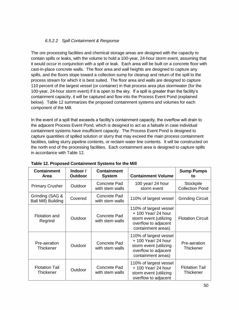
50
6.5.2.2 Spill Containment & Response
The ore processing facilities and chemical storage areas are designed with the capacity to
contain spills or leaks, with the volume to hold a 100-year, 24-hour storm event, assuming that
it would occur in conjunction with a spill or leak. Each area will be built on a concrete floor with
cast-in-place concrete walls. The floor area and wall heights are designed to capture any
spills, and the floors slope toward a collection sump for cleanup and return of the spill to the
process stream for which it is best suited. The floor area and walls are designed to capture
110 percent of the largest vessel (or container) in that process area plus stormwater (for the
100-year, 24-hour storm event) if it is open to the sky. If a spill is greater than the facility’s
containment capacity, it will be captured and flow into the Process Event Pond (explained
below). Table 12 summarizes the proposed containment systems and volumes for each
component of the Mill.
In the event of a spill that exceeds a facility’s containment capacity, the overflow will drain to
the adjacent Process Event Pond, which is designed to act as a failsafe in case individual
containment systems have insufficient capacity. The Process Event Pond is designed to
capture quantities of spilled solution or slurry that may exceed the main process containment
facilities, tailing slurry pipeline contents, or reclaim water line contents. It will be constructed on
the north end of the processing facilities. Each containment area is designed to capture spills
in accordance with Table 12.
Table 12. Proposed Containment Systems for the Mill
Containment Area
Indoor / Outdoor
Containment System Containment Volume
Sump Pumps to
Primary Crusher Outdoor Concrete Pad
with stem walls 100 year/ 24 hour
storm event Stockpile
Collection Pond
Grinding (SAG & Ball Mill) Building
Covered Concrete Pad
with stem walls 110% of largest vessel Grinding Circuit
Flotation and Regrind
Outdoor Concrete Pad
with stem walls
110% of largest vessel + 100 Year/ 24 hour storm event (utilizing overflow to adjacent containment areas)
Flotation Circuit
Pre-aeration Thickener
Outdoor Concrete Pad
with stem walls
110% of largest vessel + 100 Year/ 24 hour storm event (utilizing overflow to adjacent containment areas)
Pre-aeration Thickener
Flotation Tail Thickener
Outdoor Concrete Pad
with stem walls
110% of largest vessel + 100 Year/ 24 hour storm event (utilizing overflow to adjacent
Flotation Tail Thickener
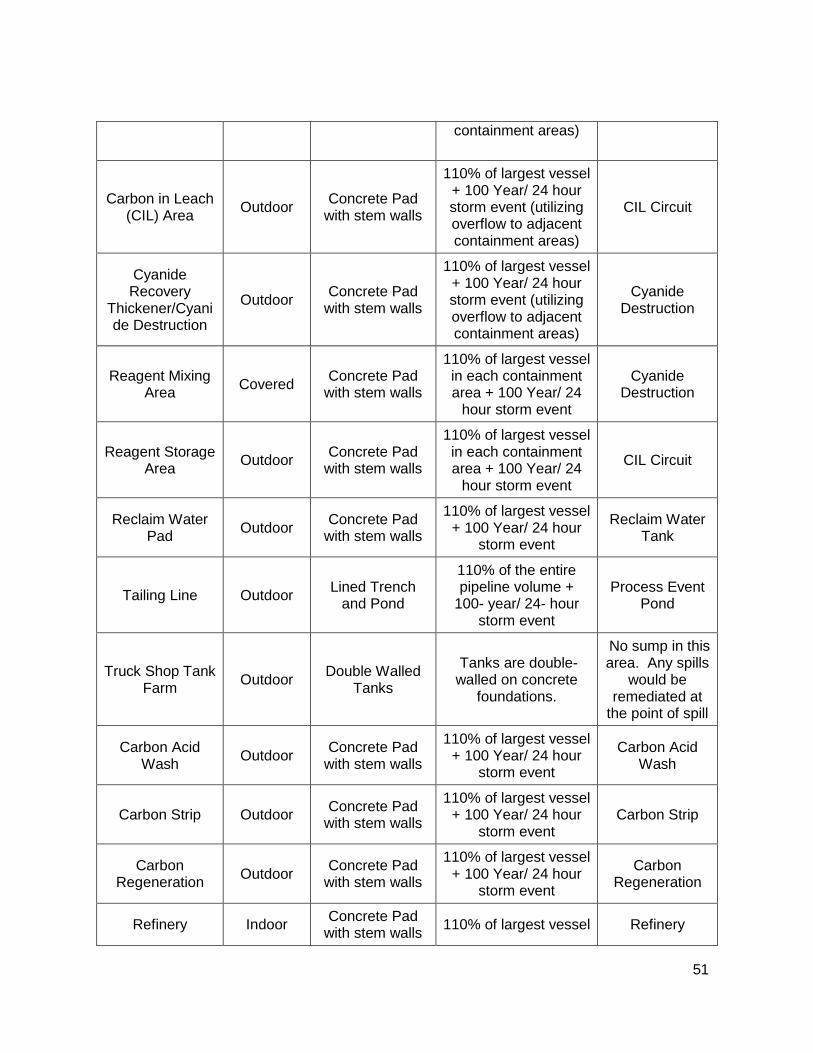
51
containment areas)
Carbon in Leach (CIL) Area
Outdoor Concrete Pad
with stem walls
110% of largest vessel + 100 Year/ 24 hour storm event (utilizing overflow to adjacent containment areas)
CIL Circuit
Cyanide Recovery
Thickener/Cyanide Destruction
Outdoor Concrete Pad
with stem walls
110% of largest vessel + 100 Year/ 24 hour storm event (utilizing overflow to adjacent containment areas)
Cyanide Destruction
Reagent Mixing Area
Covered Concrete Pad
with stem walls
110% of largest vessel in each containment area + 100 Year/ 24
hour storm event
Cyanide Destruction
Reagent Storage Area
Outdoor Concrete Pad
with stem walls
110% of largest vessel in each containment area + 100 Year/ 24
hour storm event
CIL Circuit
Reclaim Water Pad
Outdoor Concrete Pad
with stem walls
110% of largest vessel + 100 Year/ 24 hour
storm event
Reclaim Water Tank
Tailing Line Outdoor Lined Trench
and Pond
110% of the entire pipeline volume +
100- year/ 24- hour storm event
Process Event Pond
Truck Shop Tank Farm
Outdoor Double Walled
Tanks
Tanks are double-walled on concrete
foundations.
No sump in this area. Any spills
would be remediated at
the point of spill
Carbon Acid Wash
Outdoor Concrete Pad
with stem walls
110% of largest vessel + 100 Year/ 24 hour
storm event
Carbon Acid Wash
Carbon Strip Outdoor Concrete Pad
with stem walls
110% of largest vessel + 100 Year/ 24 hour
storm event Carbon Strip
Carbon Regeneration
Outdoor Concrete Pad
with stem walls
110% of largest vessel + 100 Year/ 24 hour
storm event
Carbon Regeneration
Refinery Indoor Concrete Pad
with stem walls 110% of largest vessel Refinery

52
Fuel Storage Outdoor Double Walled
Tanks
Tanks are double-walled on concrete
foundations.
No sump in this area. Any spills
would be remediated at
the point of spill
Source: Haile Draft Project Description (February 2013)
Systems and procedures at the Mill Site will be in place to address potential recovery of
released solutions, remediation of any contaminated soil, and possible failures of the tank
trucks, as necessary to protect surface and ground water.
6.5.2.3 Process Event Pond
The Process Event Pond will be approximately a 1.5 million gallon capacity HDPE-lined pond
to handle overflow events where the fluids will require treatment before release to the
environment. Should multiple spill events occur in the Mill processing area, any material that
would not fit within the containment area would flow to the Process Event Pond. The additional
solution or slurry from the failure would exit the containment area through a pipeline and would
flow by gravity within a pipe to the HDPE-lined Process Event Pond. Should a failure of the
tailing or process water pipelines occur, or in the event of a prolonged unplanned power
outage, the material from the pipelines would drain to the Process Event Pond.
Once the failures have been repaired, or power restored, the material in the Process Event
Pond would be returned to the cyanide recovery thickener or applicable area for processing.
Water from a spill or incident that contacts processing reagents would be suitable for use in the
closed-loop system, which includes use of process water from the TSF.
6.5.2.4 Monitoring Plans & Permits
The Mill and Process Event Pond will be monitored in accordance with Haile’s Mining Permit,
and operational aspects in accordance with Haile’s Operating Plans and Procedures for the
Mill, which will describe the standard practices necessary for the safe and environmentally
sound operation of the facility, and specific measures needed for compliance with applicable
regulatory requirements. Haile’s Operating Plans and Procedures for the Mill will be consistent
with the International Cyanide Management Code.
6.5.2.5 Water Quality Monitoring
Sections 2, Groundwater, and Section 3, Surface Water, provide for up-gradient and down-
gradient monitoring of the primary facilities at the Project site, to determine whether constituent
migration from the Mill is occurring, as well as appropriate reporting and response activities.

53
6.5.2.5.1 Cyanide Management
Unloading of liquid cyanide and other chemicals used at the Mill will be done on a concrete
surface to prevent any leakage from reaching the environment. Cyanide storage and mixing
tanks will be located on concrete surface to prevent seepage to the subsurface. Secondary
containment will be employed to contain any releases from the tanks, and for any
precipitation that may come in contact with the cyanide. Should there be any releases from
the tanks, the material/liquid will be recovered and returned to the cyanide process or proper
disposal of any contaminated materials.
6.5.2.6 Air Quality Control and Monitoring
Haile’s Air Quality State Construction Permit No. 1460-0070-CA and Operating Permit (not yet
issued) from the South Carolina DHEC, Bureau of Air Quality, will contain emissions
limitations, work practice standards, recordkeeping requirements, equipment monitoring
requirements and reporting obligations. See Air Construction Permit No. 1460-0070-CA,
Sections C-N.
6.5.2.7 Reporting and Management Planning
6.5.2.7.1 Federal and State Permit Reporting Requirements
Haile will follow the reporting procedures in its Air Construction Permit No. 1460-0070-CA and
Air Operating Permit or Mining Permit, as appropriate.
6.5.2.7.2 Management Planning
Haile will develop operational and management plans to ensure compliance with permit
terms, including any emergency reporting and responses.
54
6.5.3 Pipelines8
6.5.3.1 Spill Prevention, Containment & Response
The tailing slurry (from the Mill to the TSF) and process water pipelines (from the TSF to the
Mill) are designed to have double containment – with one pipe placed inside another pipe (the
containment pipe) and/or a pipe in an HDPE-lined ditch – to minimize the potential of an
accidental spill. Haile will also install pressure-sensing alarms on these pipelines.
Should a failure of the tailing or process water pipelines occur, or in the event of a prolonged
unplanned power outage, the material from the pipelines would drain to the Process Event
Pond (See Section 6.5.2.3 for details on the Process Event Pond). Once the failures have
been repaired, or power restored, the material in the Process Event Pond would be returned to
the cyanide recovery thickener or applicable area for processing. Water from a spill or incident
that contacts processing reagents would be suitable for use in the closed-loop system, which
includes use of process water from the TSF.
The contact water pipelines will carry contact water from its source to the 19 Pond for
treatment or use in the Mill. The contact water pipelines and pump systems have not yet been
designed; however, Haile expects that these will be single-wall pipes that will have differential
pressure-sensing alarms and/or an automatic shut-off system to respond to a change in
pressure in the pipe (which is a standard indicator of a potential leak).
6.5.3.2 Monitoring Plans & Permits
Tailing slurry and process water pipelines will be monitored in accordance with Haile’s Mining
Permit. Haile’s contact water pipelines from originating sources to the 19 Pond are expected to
be addressed in Haile’s CWTP Construction Permit.
6.5.3.3 Reporting and Management Planning
6.5.3.3.1 Federal and State Permit Reporting Requirements
Haile will comply with the reporting requirements in its Mining Permit and NPDES Individual
Permit, as appropriate.
6.5.3.3.2 Management Planning
8 See Haile, Draft Project Description (submitted February 22, 2013 ) for additional information
regarding the pipelines at the Project site.
55
Haile will develop operational and management plans to ensure compliance with permit
terms, including any emergency reporting and responses.
6.5.4 Stormwater Facilities, Including Roadside Ditches
Management of non-contact stormwater involves routing runoff from undisturbed areas around
mine facilities, collection of stormwater runoff from non-PAG mine facilities, sediment control
and release of non-contact waters to the stream system.
6.5.4.1 Monitoring Plans & Permits
Stormwater management will be more fully described in Haile’s Stormwater Pollution
Prevention Plan (SWPPP), which will be completed in conjunction with the NPDES Industrial
General Permit. Methods of managing sediment and erosion control during construction will
follow guidelines presented in the South Carolina Stormwater Management Handbook (DHEC
2005), and be in accordance with the NPDES Industrial Permit.
For construction activities at the Mill area, Haile will comply with the NPDES Construction
General Permit. Following construction, this area will follow the NPDES Industrial General
Permit.
6.5.4.2 Stormwater Management
Stormwater management at Haile will be guided by the regulations and standards set by the
DHEC and Haile’s current coverage under the NPDES Industrial General Permit. Presently, all
covered stormwater discharges are being managed in accordance with the requirements of the
NPDES Industrial General Permit. Regulation R61-9.122.26(b)(14) defines “Stormwater
discharge associated with industrial activity” to mean “the discharge from any conveyance that
is used for collecting and conveying stormwater and that is directly related to manufacturing,
processing or raw materials storage areas at an industrial plant. The term does not include
discharges from facilities or activities excluded from the NPDES program under this
regulation.”
The NPDES Industrial General Permit includes Part 8 (Sector-Specific Requirements for
Industrial Activity), Subpart G (Sector G-Metal Mining). The sector-specific requirements apply
to those areas of the mine facility where those sector-specific activities occur. These sector-
specific requirements are in addition to any requirements specified in the permit. Coverage is
required for metal mining facilities that discharge stormwater contaminated by contact with, or
that has come into contact with, any overburden, raw material, intermediate product, finished
product, byproduct or waste product located on the site of the operation (see Part 8.G.1,
Covered Stormwater Discharges). Part 8.G.2, Covered Discharges from Active and
Temporarily Inactive Facilities, identifies the stormwater discharges covered under Part 8,
Subpart G. In accordance with the NPDES Industrial General Permit, Part 5, Stormwater

56
Pollution Prevention Plan (SWPPP), Haile will update its existing SWPPP to document the
selection design, and installation of control measures, and implementation (including
inspections, maintenance, monitoring, and corrective action) of the permit requirements.
DHEC has determined that construction of the Mill Site will require coverage under the NPDES
Construction General Permit and associated SWPPP for stormwater discharges associated
with construction. As a result, Haile submitted its Notice of Intent (NOI) for coverage under the
NPDES Construction General Permit to DHEC on June 28, 2013. Upon completion of the
construction activities for the Mill Site, stormwater discharges associated with industrial
activities at the Mill Site will return to being regulated by the NPDES Industrial General Permit.
Other earthmoving activities at the mine are covered by the NPDES Industrial General Permit.
Stormwater control design measures and implementation procedures are in process for
several of the planned facilities at the mine site, and Haile is working with DHEC to ensure
compliance with all stormwater permitting requirements. Haile will have complete stormwater
plans, which will have been reviewed by DHEC, prior to conducting any construction and
industrial activities not otherwise covered under the current NPDES Industrial General Permit.
6.5.4.3 Reporting and Management Planning
6.5.4.3.1 Federal and State Permit Reporting Requirements
Haile will comply with the reporting requirements in Section 7.0 and Part 8, Sector G, 8.G.8 of
the NPDES Industrial General Permit and in Appendix C of the NPDES Construction General
Permit.
6.5.4.3.2 Management Planning
6.5.4.3.2.1 NPDES Industrial General Permit
Under the NPDES Industrial General Permit, Haile must report any noncompliance which may
endanger health or the environment. Any information must be provided orally to DHEC
within 24 hours from the time Haile becomes aware of the circumstances. A written
submission to DHEC must also be provided within five days of the time Haile becomes aware
of the circumstances.
Under the NPDES Industrial General Permit, if follow-up monitoring (as defined in Section 6.3
of the permit) exceeds a numeric effluent limit, Haile must submit an Exceedance Report to
DHEC no later than 30 days after it has received its lab results. Haile’s report must include
the following:
a. NPDES permit tracking number;

57
b. Facility name, physical address and location;
c. Name of receiving water;
d. Monitoring data from this and the preceding monitoring event(s);
e. An explanation of the situation; what Haile has done and intends to do (should the
Company’s corrective actions not yet be complete) to correct the violation; and
f. An appropriate contact name and phone number.
6.5.4.3.2.2 NPDES Construction General Permit
Under the NPDES Construction General Permit, Haile shall report to DHEC any
noncompliance which may endanger health or the environment. Any information shall be
provided orally within 24 hours from the time Haile becomes aware of the circumstances. A
written submission to DHEC shall also be provided within 5 days of the time Haile becomes
aware of the circumstances. The written submission shall contain:
a. A description of the noncompliance and its cause;
b. The period of noncompliance, including exact dates and times, and if the noncompliance
has not been corrected, the anticipated time it is expected to continue;
c. And steps taken or planned to reduce, eliminate, and prevent reoccurrence of the
noncompliance.
Under the NPDES Construction General Permit, Haile shall report to DHEC all other instances
of noncompliance at the time monitoring reports are submitted. The monitoring reports shall
contain the above-listed information.

58
7 Reclamation Plan, Post-Mining Reclamation and Closure Monitoring9
The Haile Gold Mine Reclamation Plan has been developed to meet the requirements of
Section 48-20-90 of the South Carolina Mining Act. The Reclamation Plan (DATE) is designed
to describe methods used to reclaim land disturbed by mining, ore processing operations, and
associated activities to a stabilized condition that will provide for the long-term protection of
land and water resources, minimize the adverse impacts of mining, and support the intended
post-mining land use.
In addition, the Reclamation Plan serves as a basis for calculating reclamation costs,
identifying long-term post-reclamation monitoring and maintenance requirements, and
determining financial assurance. As mining activities at the Haile Gold Mine progress, the
Reclamation Plan will be continuously refined and expanded, while adhering to the concepts
outlined therein. Appropriate financial assurance will be provided for proposed reclamation
and closure activities to ensure that funds for reclamation and closure are available.
Due to its past reclamation successes at the Haile Gold Mine site, Haile has experience and
understanding of the reclamation process, including what vegetation can and will grow at the
site. During mining operations, Haile will take every opportunity to perform reclamation
concurrent with operations. Concurrent reclamation will be performed on disturbed areas once
all planned mining activities in the area are completed and no future mining activity is
expected. Final reclamation will be completed as soon as practicable after mining activities
cease at the facility. Haile will also conduct post-mining reclamation and closure maintenance
and monitoring.
7.1 Site-Wide Reclamation Plan
The Haile Gold Mine Reclamation Plan describes the reclamation of disturbed land from
mining and ore processing operations to a stabilized condition that will provide for the long-
term protection of land and water resources for post-mining land uses. Additional goals
include:
• Reducing the environmental impacts of mining.
9 Haile’s reclamation activities are more fully described in its Reclamation Plan (DATE). For
additional information on anticipated soil erosion from HDPE-covered facilities, see AMEC, Soil
Erosion Loss Analysis (August 2013), which is Appendix A of the Reclamation Plan.
59
• Utilizing concurrent reclamation where appropriate throughout the mining process .
• Minimizing the need for long-term active water management requirements through the
conversion to and use of passive treatment technology at the TSF and Johnny’s PAG.
• Abating the generation of acid rock drainage from the sulfide materials exposed as a
result of the mining operations.
• Meeting state and federal regulatory requirements.
During operations, Haile will perform aspects of the final reclamation activities as part of
operational activities. This concurrent reclamation is planned for stabilization and vegetation of
the outboard slopes of the TSF and OSAs, backfill and reclamation of certain mine pits, and
grading and reseeding areas where previously reclaimed facilities were removed. Final
reclamation (which is anticipated to include reclamation of the TSF, Johnny’s PAG, the Mill
Site, roads, pit lakes, and the associated revegetation efforts) will begin immediately upon
cessation of mining and milling operations. Reclamation will be completed as expeditiously as
practicable and in compliance with SC Mining Regulations 89-80.B: “Reclamation shall be
conducted simultaneously with mining whenever feasible and in any event shall be initiated at
the earliest practicable time, but no later than within 180 days following termination of mining
on any segment of the mine and shall be completed within two years after completion or
termination of mining on any segment of the mine.”
7.2 Vegetation Plan
Re-establishing vegetation on impacted lands will be essential to preventing erosion, restoring
surface stability, providing site productivity, and providing wildlife forage/cover opportunities as
well as visual/aesthetic values at the Haile Gold Mine Project site during operations and
reclamation. The vegetation procedures planned for the Haile site are based on industry
standards, site specific experience in South Carolina, and past reclamation success. Appendix
B of the Reclamation Plan (DATE) provides the proposed seed mixes.
Generally speaking, two seed mixes are proposed to be used at Haile. One is a standard seed
mix and the second is a wetland seed mix. Haile is not currently proposing any “other
plantings.” All seed shall be certified noxious weed-free. The standard seed mix was chosen
based on species characteristics, varied soil conditions at site, and the planned land use and
maintenance of the area. An annual grass is used in the mix and will change dependent on
the time of year the planting is made. The primary goal of revegetation is soil stabilization
while a secondary goal is to provide a habitat for wildlife and the natural succession of
vegetation.
During the mine operating period, Haile will consult with SCDNR and DHEC, establish
vegetation test plots and perform other studies to establish, confirm and refine appropriate
60
vegetation species and seeding rates, determine the need for soil amendments, and determine
overall vegetation procedures to ensure sustainable vegetation post-mining for the intended
land use.
Based on previous experience at the mine site, Haile believes that the majority of the disturbed
surfaces will be suitable to sustain vegetation without the need to supplement the soil. This
assumption will be verified with test plots and vegetative studies during operations. As a
precaution, however, sufficient growth media will be stockpiled during mine development to
fully reclaim the site in accordance with SC Mining Regulation 89-140. Where Haile, in
conjunction with the State, determines that growth media is needed to establish vegetation,
material will be recovered from the storage areas and used during reclamation activities.
Opportunities for concurrent reclamation are expected to arise within the first three years of
mining activities. Therefore, vegetation studies will begin as soon as practicable following
commencement of mining activities. Previous revegetation success and concurrent
reclamation activities will be used to refine revegetation techniques throughout the mine life.
7.3 Post-Mining Land Use
Consistent with the individual locations that will be reclaimed as described in Sections 7.4.1 to
7.4.8, the goal of Haile’s reclamation plan is to return the disturbed areas to a stable condition
that can support a productive post-mining land use. After reclamation, assuming such uses
are consistent with local zoning laws, the majority of the site will be suitable for other uses (i.e.,
industrial, commercial, residential, and agriculture & forestry), restored to their natural condition
(i.e., wetlands and streams), or reclaimed as pit lakes. Future activities at the TSF and
Johnny’s PAG will be limited, consistent with post-closure restrictions.
7.4 Proposed Facilities
The proposed facilities at the Haile Gold Mine that are addressed in the Reclamation Plan
(DATE) include:
• Backfilled Mine Pits
• Pit Lakes
• Green OSAs
• Johnny’s PAG
• Site surface water management facilities
61
• TSF
• Mill Site and associated infrastructure
• Roads, on-site power lines, and other ancillary facilities
Following is an overview of the proposed reclamation activities planned for the above facilities:
7.4.1 Backfilled Mine Pits
Mill Zone, Haile, Red Hill, and Chase Pits will be completely backfilled with overburden and the
Snake Pit will be partially backfilled with overburden and reclaimed to facilitate post mining land
uses. A reclamation approach for each pit has been designed to best suit the location,
geometry, and timing of mining within the scope of the current mine plan and reclamation
concepts. Generally speaking, these pits will be backfilled with Yellow and Green overburden
as part of overburden placement during operations (i.e., concurrent backfilling).
As Yellow overburden material is placed in the pit backfill, the overburden will be amended with
lime at a rate of 2 lbs per ton of overburden.10 Lime amendment will assist in neutralizing acid
rock drainage that forms within the pit backfill material until depressurization activities cease,
and the water level in the pit backfill has risen so as to fully inundate the yellow overburden.
Yellow overburden will be placed using lift heights no greater than 50 feet.
The final lift of Yellow overburden will stop a minimum of 5 feet below the anticipated
inundation level (based on historic levels and groundwater modeling). Above the Yellow
overburden, a minimum of 5 feet of saprolite will be placed to reduce oxygen entry into the
backfill. Once water levels in the pit backfill have recovered to the inundation level, the Yellow
overburden will be permanently submerged, limiting the oxygen available and thereby reducing
the potential to generate acid rock drainage.
The top of the backfill will be regraded to minimize impoundment of storm waters and flow
concentration. Occasional large boulders that are uncovered during re-grading may be left on
the surface to provide topographic diversity, microhabitats for wildlife and vegetation, and to
break the linear appearance of the final slope.
10 This rate is based on current studies of the expected backfill material geochemistry
conducted to date and may be adjusted during operations based on on-going sampling and
testing of overburden material during mining operations, and DHEC approval.

62
The backfilled surface will be seeded using an approved seed mix and appropriate seeding
methods, described above in Section 7.2. Agricultural, forestry and hunting are anticipated
appropriate future uses of these areas.
7.4.2 Pit Lakes
Ledbetter, Champion and Small Pits will not be backfilled during operations and will be
reclaimed as pit Lakes. As noted above, the portion of Snake Pit that is not backfilled will also
be reclaimed as a lake which would become part of the Ledbetter Pit Lake. A safety berm will
be constructed around any portions of the Pit Lakes that did not have these during operations.
Appropriate signage will be placed at regular intervals on the berm warning of the hazards of
the pit highwall and pit lake.
Pit lake water quality studies have been performed based on pre-mining information (Schafer,
2011) (Arcadis, 2012). They indicate that water quality of the pit lakes will meet water quality
standards. With lime addition, all pit lakes can be maintained with a neutral to alkaline pH
level. Ledbetter Pit Lake is predicted to require lime addition for 13 years and Champion for 17
years after filling commences. A long-term annual lime requirement will be required at the
Small Pit Lake after filling commences. However, once groundwater modeling has been
completed, these estimates may be revised.
During operations, as additional information is acquired related to acid generating
characteristics of the pit walls and refined groundwater modeling, an additional pit lake study
will be performed to refine the predictions of the quantity and water quality of the expected pit
lakes.
During pit filling and until stability has been achieved, the pit lake water quality in the pit lakes
will be monitored and managed to insure water quality meets applicable requirements. Lime
will be added, as necessary, to maintain the pit lakes with an appropriate pH level.
7.4.3 Johnny’s PAG
One OSA, Johnny’s PAG, will be designated to receive all Red overburden and any Yellow
overburden not utilized for the pit backfills. Low grade ore will also be stored within the lined
area of Johnny’s PAG; however, the plan is to remove and process the low grade ore prior to
final closure and reclamation of Johnny’s PAG. Any low grade ore left within Johnny’s PAG
would be closed and reclaimed with the Red/Yellow overburden. Additionally, spent ore from
the existing Chase and South Heap Leach Pads and existing passive cell material will be
placed in Johnny’s PAG; Red or Yellow material from existing overburden facilities and backfill
material from previously backfilled pits that are within the proposed pit footprints will be placed
in Johnny’s PAG.
63
Johnny’s PAG will be constructed with an 80-mil thick, HDPE geomembrane liner underlain
with low permeability soils in order to contain and route seepage and runoff waters to two
collection ponds (the 465 and 469 Collection Ponds) for water treatment. The HDPE liner
would be overlaid with two (2) feet of sand, to protect the liner during operations and removal
of the low grade ore stockpile for processing at the Mill. Collection channels are built within the
HDPE-lined facility and surround Johnny’s PAG to divert untreated surface runoff and seepage
from the PAG to HDPE-lined collection ponds that have been sized to capture the 100-year 24-
hour precipitation event. Groundwater would be routed under Johnny’s PAG to avoid contact
via collection pipes that would be installed below the low- permeability soil liner to route
groundwater from beneath the facility.
Red PAG will be placed in lifts not more than 50 feet in height. The outside perimeter of each
bench will contain a minimum 20 foot wedge of saprolite. Also, the top of each bench will be
compacted. These measures will help minimize oxygen and meteoric water entry/infiltration
into the pile. The top surface of the regraded PAG will be covered with a minimum five (5) feet
of saprolite cover.
Once the pile is constructed and capped to final configuration, the entire surface of Johnny’s
PAG will be covered with a double textured HDPE geomembrane to limit the infiltration of water
and restrict oxygen movement. A minimum of two feet of growth media material will be placed
on top of the liner. The growth media will be vegetated. See Section 7.2. Once vegetated, a
petition to re-classify stormwater as non-contact will be submitted to DHEC. After DHEC
approves, runoff will be treated as stormwater.
After the geomembrane cover is installed and infiltration into the OSA is cut off, seepage from
Johnny’s PAG is anticipated to report to the seepage collection pond at a low flow rate and be
of poor quality for an extended duration. However, the quantity of seepage is expected to
decrease quickly once the HDPE cover is installed and additional precipitation is prevented
from infiltrating the PAG material. Haile anticipates that the long term treatment of this flow will
be performed using a passive treatment facility. Unless and until the flow is capable of being
treated by passive technology, Haile will use the on-site CWTP to treat and discharge the
seepage from Johnny’s PAG.
Construction and operation of the proposed passive wastewater treatment facility is regulated
by the DHEC.
These passive treatment systems will treat the seepage using an anaerobic (no-oxygen)
treatment cell filled with organic media containing beneficial bacteria followed by an aerobic
(with oxygen) polishing treatment cell and discharge. The 465 and 469 Collection Ponds
currently proposed for Johnny’s PAG will each be of sufficient size to contain a passive
treatment system capable of addressing the effluent from their portion of Johnny’s PAG.
64
Passive systems use gravity to move the water. The system is planned to be constructed in
the lined 465 and 469 Collection Ponds. Due to the passive (no pumping) nature of the
system, the maintenance is expected to be minimal. The media in the cells have been
assumed to require replacement every 20 years for bonding purposes.
7.4.4 Green OSAs
Six OSAs are designated to receive only Green overburden (601, Ramona, Hayworth, Hilltop,
James, and Robert OSAs). All operational slopes of the OSAs will be constructed with
alternating benches and angle of repose slopes to have an overall slope no steeper than
3H:1V. Concurrent with placement of the overburden, the angle of repose slopes will be
pushed down to develop inter-bench slopes of 2.5H:1V slopes with surface water controls to
limit erosion. Benches will remain to provide surface water control to limit erosion from the
slope face. Any portion of the OSA that can be safely accessed without impacting overburden
placement will be regraded in this manner concurrent with mining activities.
Once final reclamation of a facility has begun, any remaining regrading will be performed to
achieve the above configuration over the remainder of the OSA slopes. Additionally, access
ramps will be removed or reduced, the top surface will be regraded to promote drainage and
minimize erosion, and any additional surface water control features that are needed for
reclamation will be shaped into the overburden surface. During final grading, occasional large
boulders that are uncovered during sloping may be left on the surface to provide topographic
diversity, microhabitats for wildlife and vegetation, and to break the linear appearance of the
final slope.
7.4.5 Site Surface Water Management
The development and active mining of the Mill Zone, Haile, Red Hill, Snake and Ledbetter Pits
will impact stretches of Haile Gold Mine Creek and North Fork Creek. Stream diversions will
commence during Pre-Production.
As the South Pit complex is backfilled and reclamation is completed, the North Fork Creek
drainage will be re-established on the surface of the backfill. However, restoring of the flow in
the re-established stream will not be done immediately. The North Fork diversion pipe is
expected to be relocated from the Mill Zone diversion bench on the west side of the pit
adjacent to the newly reestablished stream gradient. The re-established portion of the North
Fork Creek will meet the undisturbed portion of the North Fork Creek on the downgradient
edge of the backfilled South Pit. Haile expects that the North Fork stream flow will be
maintained in the relocated diversion pipe for several years before removing the pipe and
returning flows to the reestablished channel, after settling of backfilled locations and
appropriate establishment and stabilization of a stream bed. Erosion controls, such as riprap
or gabion structures will be installed to limit erosion of the main channel and vegetated

65
overbanks These diversions will be constructed to convey the flow from the 100-yr, 24-hr
storm event.
A portion of Haile Gold Mine Creek flow (downstream of the Ledbetter Pit) that is in the
diversion pipe on the Red Hill and Haile diversion bench will be relocated to flow in a
reconstructed stream placed over the Red Hill and Haile Pits backfilled area. This
reconstructed channel is planned to join a portion of the North Fork and then flow into Haile
Gold Mine Creek. The Haile Gold Mine Creek Detention and Diversion Structure and pipes will
either be modified and remain in place above this reconstructed channel, or replaced with a
low head dam. The Haile Gold Mine Creek flow from upstream of the Ledbetter Pit will be split
between a diversion to allow some flow into Ledbetter Pit Lake and some flow through the
diversion pipes to the reconstructed stream channel. Haile will divert flow into the Ledbetter Pit
Lake only as may be authorized by the South Carolina DHEC, Bureau of Water, Surface Water
Withdrawal Permitting Section standards consistent with State standards for “safe yield” from
the creek. See Haile, Anticipated Mine Production and Operations (Supplemental Report
December 2012) for further details.
The reestablished stream channels (North Fork and HGMC) will be designed to function as
natural streams, with appropriate sinuosity and the potential for adjacent wetland
establishment. Wetlands impacted by construction of road crossings (culverts or bridges) will
be reclaimed using the wetland seed mix.
Upon the filling of Ledbetter Pit Lake to equilibrium (approximately 95%), the Haile Gold Mine
Creek Detention and Diversion Structure / low head dam is expected to be removed and all
streamflows in Haile Gold Mine Creek will flow into Ledbetter Pit Lake with flows exiting the pit
lake through an engineered outlet structure into the reestablished downstream channel. It is
expected that filling of the Ledbetter Pit Lake to equilibrium will take approximately 20 years
post mining and the engineered outlet structure will be designed prior to this time in
cooperation with DHEC. The plan is to allow the upper Haile Gold Mine Creek to flow through
the Ledbetter Pit Lake, out of Ledbetter Pit Lake through an engineered outlet structure, into
reestablished stream channels constructed over the backfilled pits, into the Lower Haile Gold
Mine Creek, and into the Little Lynches River.
7.4.6 Tailing Storage Facility
The TSF will be constructed using conventional downstream construction methods to raise the
embankment in four stages. The site topography is such that to achieve the total storage
capacity the embankment will be a four-sided ring dike configuration, approximately 5,500 feet
by 3,500 feet along the embankment crest centerline for the longest embankment legs.
The facility will be underlain by a composite liner consisting of a low permeable soil liner and a
60 mil HDPE liner. An underdrain system over the 60 mil HDPE liner system will collect
seepage from the tailing and convey it by gravity to the Underdrain Collection Pond at the toe

66
of the southwest embankment. Groundwater will be routed under the TSF in collection pipes
installed below the HDPE and low-permeability soil liner to route groundwater from beneath the
facility (to avoid contact with the tailing material).
As the outboard slopes of the TSF achieve final configuration, they will be vegetated using
established procedures. See Section 7.2 for details.
At the cessation of milling, the TSF will be reclaimed using a dry closure approach. In order to
dewater the tailing facility, the CWTP will be reconfigured to treat the water within the tailing
impoundment and Underdrain Collection Pond. Water collected from the Underdrain
Collection Pond and any remaining free water in the impoundment will be treated in the
reconfigured water treatment plant and discharged though the same outfall used during
operations.
As consolidation in an area of the tailing nears completion, that portion of the tailing will be
covered with a smooth HDPE geomembrane laid directly on the tailing surface or foundation
layer. The geomembrane will limit infiltration and will reduce long term seepage to the TSF
underdrains, allowing the eventual use of passive treatment technology. The geomembrane
cover will extend over the entire tailing surface to the edge of the TSF impoundment and will be
sealed directly to the exposed TSF geomembrane liner at the perimeter of the TSF.
Following placement of the geomembrane cover, a minimum 2-foot thick layer of growth media
will be placed over the geomembrane to protect it from damage, UV radiation, and freezing and
to provide a soil layer for establishing vegetation. The growth media will be placed over any
exposed geomembrane liner on the interior TSF embankment and the top of the TSF
embankment, extending to the outboard slopes of the TSF embankment. The surface the
embankment will be graded to allow precipitation on this surface to drain to the outside of the
TSF embankment. The final surface will be vegetated with an approved seed mix and
established seeding methods. See Section 7.2 for details.
Draindown would continue to be collected in the TSF Underdrain Collection Pond and treated
as provided for under the NPDES permit until the seepage is determined to be at the point
where a passive treatment cell can treat the volume of flow from the seepage collection
system. As described for Johnny’s PAG, see Section 7.4.3, the passive treatment cell will
improve the water chemistry of the seepage to acceptable levels for state permitting
requirements. As with all passive treatment system, the nature of the organic strata must be
specifically tailored to the effluent stream, and permitted by DHEC.
7.4.7 Borrow Areas
Two borrow areas (Holly and Hock) will be developed to provide material for construction and
expansion of the TSF. Borrow material from these two locations will be used for the second
stage of construction in Year 2 and the third stage of construction scheduled for Year 4. Once

67
material from the borrow areas have been exhausted the areas will be reclaimed. Haile
anticipates that the Holly Borrow Area will be reclaimed following completion of the second
stage of the TSF expansion and the Hock Borrow Area will be reclaimed after the third stage of
the TSF expansion.
During removal of material for construction from both borrow areas, slopes on the edges of the
borrow areas will be maintained at a 3H:1V or shallower. Since material is being removed to
lower the elevation without creating pits, slope grading should be minimal during reclamation.
Also during operations, slopes retained within the borrow areas will allow precipitation to flow
off the areas and not create pooling. Reclamation of the borrow areas will include scarifying to
loosen compacted soils and revegetating with an approved seed mix using approved seeding
techniques.
7.4.8 Ancillary Facilities
Haile anticipates that other facilities at the mine, including the Mill Site, growth media storage
areas, sediment and settling ponds, disturbed land, roads, power lines, pipelines and surface
water controls, that are not required for post-mining monitoring or maintenance will be
regraded, demolished, salvaged and/or removed as appropriate. Specific areas (such as
portions of the Mill Site) will be covered with a layer of growth media. All disturbed areas will
be vegetated using established procedures.
7.5 Post-Mining Reclamation and Closure Monitoring
Haile will conduct post-mining reclamation and closure monitoring for purposes of ensuring
continued compliance with permit requirements. However, Haile expects that a Post-Closure
Water Quality Monitoring and Management Plan will be adapted from the operational water
quality plan. In addition, monitoring will be coordinated with requirements of permits in effect.
Overall objectives are to demonstrate that receiving waters are meeting water quality criteria.
Secondarily, the plan will provide early warning of water impacts and a means of identifying
contaminant sources. Finally, the plan will identify contingency actions that will be employed if
monitoring objectives are not satisfied.
Haile will develop a detailed post mining monitoring plan prior to mine closure based on a
continuation of the operational monitoring plan. As noted above in Sections 2 and 3, Haile
anticipates that the operational monitoring plan will have sampling sites in surface and
groundwater that provide up-gradient and down-gradient monitoring. These sites may also be
suitable for post mining monitoring. It will also include required discharge monitoring.
The Post-Mining Reclamation and Closure Water Quality Monitoring and Management Plan
will be designed to assure:

68
Surface and ground waters are monitored up gradient and down gradient (as
appropriate) of permanent post mining features.
There is monitoring in place between any potential sources of contamination and
receiving waters to provide for adequate response time.
All discharges are monitored in accordance with applicable regulation.
Any known sources of contamination are appropriately monitored.
Post mining monitoring for a period specified by regulation or agency requirements.
Groundwater monitoring will be used to determine the performance of reclaimed and closed
facilities that may have subsurface discharges. Selected wells will be used to assess the
potential loads contributed to groundwater from various facilities. Actual monitoring locations
will be designated in plans submitted before final reclamation commences. These points will be
selected for their ability to provide pertinent information on up gradient and down gradient
water quality.
Based on early post-mining monitoring, the parameter list and sampling frequency may be
adjusted to reflect the observed conditions. The parameters analyzed will be selected based
on parameters observed during operations and having the potential to adversely impact water
quality downstream.

69
Table 13. Proposed General Mining Schedule for Pit Development and Site Reclamation
Source: Haile Draft Project Description (February 2013). Note: For Champion and Small Pit Lakes, this is the time-frame to reach 95% full. 1
st half of Johnny’s PAG is constructed and begins receiving material in
Pre-Production. *Period of monitoring will be in accordance with DHEC regulations.

70
7.6 Post-Mining Care and Maintenance
The reclamation designs for the facilities at the Haile Site were developed to reduce the need for
long-term care and maintenance. Haile anticipates that DHEC will require staged-level monitoring
at the Site that will be reduced or terminated (for specific facilities) over the life of the mine, based
upon Haile demonstrating that its reclamation and closure designs meet physical and chemical
performance standards on a facility-by-facility basis.
The use of passive treatment cells for ongoing treatment of the drainage effluent from the TSF
and Johnny’s PAG are expected to function over the long term, but will require periodic
replacement of the organic media within the facility. Haile has assumed that the cells will require
replacement approximately every 20 years, or as necessary (based on the functionality of the
media).
Maintenance of vegetation will also be required on Johnny’s PAG and the TSF following closure.
Maintenance activities would be conducted to prevent woody species from becoming established.
Haile will accomplish this via chemical application (i.e., spot spraying) and/or mechanical (i.e.,
bush hogging) every two to five years, or as otherwise required by DHEC.
Additional maintenance costs will include the addition of lime to the pit lakes to maintain a neutral
pH until the water level inundates any potential acid generating material in the pit walls. Haile
anticipates that lime would be added to Ledbetter Pit Lake for approximately 13 years and to
Champion Pit for 17 years, after pit filling commences. Small Pit would require lime addition on an
annual basis after filling commences. See Section 7.4.2. However, once groundwater modeling
has been completed, these estimates may be revised.
Post-mining monitoring and maintenance will also consist of surface and groundwater monitoring
on a Site-wide basis beginning in Year 15 of the Mine Schedule (surface and groundwater will
also be monitored during Years 0-14 as part of operations) and continue for approximately 30
years after the Pit Lakes reach equilibrium (i.e., until Year 63 of the Mine Schedule). However, it
is expected that the intensity and frequency of the surface and groundwater monitoring would be
decreased over time as performance standards are achieved, until eliminated.
Importantly, however, DHEC and Haile will be better able to determine appropriate post-mining
monitoring and management obligations, as well as the appropriate length of time for which these
activities should occur, once reclamation activities are underway and more Site-specific
information is available.

71
8 Cultural Resource Monitoring
8.1 Cultural Resources Management Plan
[PAGE INTENTIONALLY LEFT BLANK]

72
9 References
Arcadis, Ecological Risk Assessment for the Proposed Future Ledbetter Pit Lake (April 2012).
AMEC, Tailing Storage Facility Operations, Inspection and Maintenance Manual (August 2013)
AMEC, Tailing Storage Facility Emergency Action Plan (June 2013)
ERC, Wetland Monitoring Plan (February 2013)
Haile, Cultural Resources Management Plan (DATE)
Haile, TSF Dam Permit Application (September 2012)
Haile, Anticipated Mine Production and Operations (Supplemental Report December 2012)
(submitted in response to RAI 2-GI-06 on January 10, 2013)
Haile, Draft Project Description (February 2013)
Haile, Reclamation Plan (DATE)
Haile, Water Resources Inventory (2013)
International Cyanide Management Code (ICMC 2012)
National Bald Eagle Management Guidelines (USFWS 2007)
Revised Mitigation Plan (July 2013)
Schafer Limited LLC, Overburden Management Plan (November 2010)
Schafer Limited LLC, Haile Gold Mine Post-Closure Water Quality Impact Evaluation (May 2011).
Schafer Limited LLC, Draft Revised Post-Closure Water Quality Impact Evaluation (February
2013)
South Carolina Stormwater Management Handbook (SCDHEC 2005)
Suggested Practices for Avian Protection on Power Lines -The State of the Art in 2006 (APLIC
2006)

This page is left blank intentionally.


