APPENDIx c - UNESCO | Building peace in the minds of men …€¦ · · 2016-03-03hull that...
11
Author Christopher J. Underwood APPENDIX C Introduction to Metal Shipbuilding Technology
Transcript of APPENDIx c - UNESCO | Building peace in the minds of men …€¦ · · 2016-03-03hull that...
Author Christopher J. Underwood
The Protection of the Underwater Cultural Heritage
APPENDIx c
Introduction to Metal Shipbuilding Technology

APPENDIx c
Core Knowledge of the Appendix ................................................ 2
Introduction to the Appendix ........................................................ 2
1 Metal Ship Construction .................................................... 3
2 Description of the Main Structural Features ............... 4
Appendix Summary ......................................................................... 15
Suggested Timetable ...................................................................... 16
Teaching Suggestions ..................................................................... 16
Suggested Reading: Full List ..........................................................17
APPENDIx c Contents
Published by UNESCO BangkokAsia and Pacific Regional Bureau for EducationMom Luang Pin Malakul Centenary Building920 Sukhumvit Road, Prakanong, KlongtoeyBangkok 10110, Thailand
© UNESCO 2012All rights reserved
ISBN: 978-92-9223-413-3 (Print version) ISBN: 978-92-9223-414-0 (Electronic version)
The designations employed and the presentation of material throughout this publication do not imply the expression of any opinion whatsoever on the part of UNESCO concerning the legal status of any country, terri-tory, city or area or of its authorities, or concerning the delimitation of its frontiers or boundaries.
The authors are responsible for the choice and the presentation of the facts contained in this book and for the opinions expressed therein, which are not necessarily those of UNESCO and do not commit the organization.
UNESCO Bangkok is committed to widely disseminating information and to this end welcomes enquiries for reprints, adaptations, republishing or translating this or other publications. Please contact [email protected] for further information.
Technical editing: Martijn M. Manders and Christopher J. UnderwoodCopy-editing: Sara M. Mabelis Design/Layout/Illustration: Warren FieldCover photo: The Mannok Shipwreck Site. © UAD, Thailand
Printed in Thailand
CLT/12/OS/015

2
Training Manual for the UNESCO Foundation Course on the Protection and Management of Underwater Cultural Heritage in Asia and the Pacific A P P E N D I X C I N T R O D U C T I O N TO M E TA L S H I P B U I L D I N G T E C H N O LO G Y
3
APPENDIx c
2
Core Knowledge of the Appendix
On completion of the Introduction to Metal Shipbuilding Technology appendix students will:
• Understand the various factors that influence the design of vessels
• Understand how vessels gradually evolved from wood to metal and from sail to steam in different geographic regions
• Have knowledge of the terminology and function of the main structural components of metal ships
• Have knowledge of the terminology and function of the propulsion system of a metal steamship
• Have knowledge of the terminology and function of deck fixtures and fittings
• Understand how nautical terms are a technical language
• Understand how a shipwreck can be identified by the study of its structure
• Understand how a metal shipwreck’s structural integrity will deteriorate at varying rates according to the site’s environmental conditions
• Have knowledge of where and in what condition, structural components, fixtures and fittings are commonly found on wreck sites
Introduction to the AppendixThis appendix provides students with sufficient knowledge of metal shipbuilding technology to enable an assessment of the Mannok shipwreck site (see Additional Information 1) and is in addition to Unit 14: Asian Shipbuilding Technology.
This appendix assumes that students have a low level of prior knowl-edge of the subject and is therefore aimed at providing an introduc-tion to metal ship construction, propulsion, fixtures and fittings.
Although some components referred to, such as the lower structural features, (keel, keelson, floors and the propeller) are not currently visible on the Mannok wreck site they are fundamental parts of a metal steam powered vessel and so are included.
1 Metal Ship Construction
For the purposes of the Foundation Course, students require the knowledge to:
• Identify, interpret and assess the condition of the main structural components of the Mannok shipwreck including parts of the propulsion system and other fixtures and fittings
• Recognize and interpret the cultural objects that form part of the site, plus other material that although forms part of the wreck site, is not an original part of the site. (See Additional Information 2)
To place the content in a cultural heritage/archaeological context, and although Unit 14 has covered these topics, this lecture also reminds students that the same rela-tionships apply to metal shipwrecks:
• How the relationships between factors such as ideology, technology, tradition, economy, use, climate and materials, influence the construction of (metal) vessels
• The importance of studying material cultural remains from different perspectives, including historical, techno-logical and social
• The transition from wooden to metal vessels is not the same in all geographic regions (See Additional Information 3)
• In common with wooden vessels, metal vessels are designed for specific purposes, for example, war and trade and fishing, but within these categories there is a large variety of shape, size and design
APPENDIx c Introduction to Metal Shipbuilding Technology
Author Christopher J. Underwood
Plan of the Mannok Island shipwreck. © UNESCO
ADDITIONAL INFORMATION
1 The assessment forms part of the development of a management plan for the wreck site, as well as provid-ing information for the story-boards in Unit 16: Museology.
2 Within the wreck site there are numerous objects associ-ated with fishing, including small clusters of rocks roped together or in small nets to form anchors or net weights, larger fish traps, as well as detritus such as bottles, cans, plastics, etc.
3 Transition from wood to metal and from sail to steam. These factors are particularly important for courses in other geographic regions where there might be different traditions.
This is illustrated using the example of copper nails in the Bronze Age wreck Kyrenia and the use of iron fastenings in predominantly wooden constructed Euro-pean vessels, dating from the fifth century AD. (See Suggested Reading: Milne, G. McKewan. C. and Goodburn, D. (1998). This then evolves into the use of more sub-stantial structural ship com-ponents, such as iron knees from the seventeenth cen-tury (See Suggested Reading: Goodwin, P. 1997), iron-clad steam powered vessels in the mid-nineteenth century, to the metal steam powered vessels characteristic of the late nineteenth and early twen tieth century.
4
Training Manual for the UNESCO Foundation Course on the Protection and Management of Underwater Cultural Heritage in Asia and the Pacific A P P E N D I X C I N T R O D U C T I O N TO M E TA L S H I P B U I L D I N G T E C H N O LO G Y
5
APPENDIx c
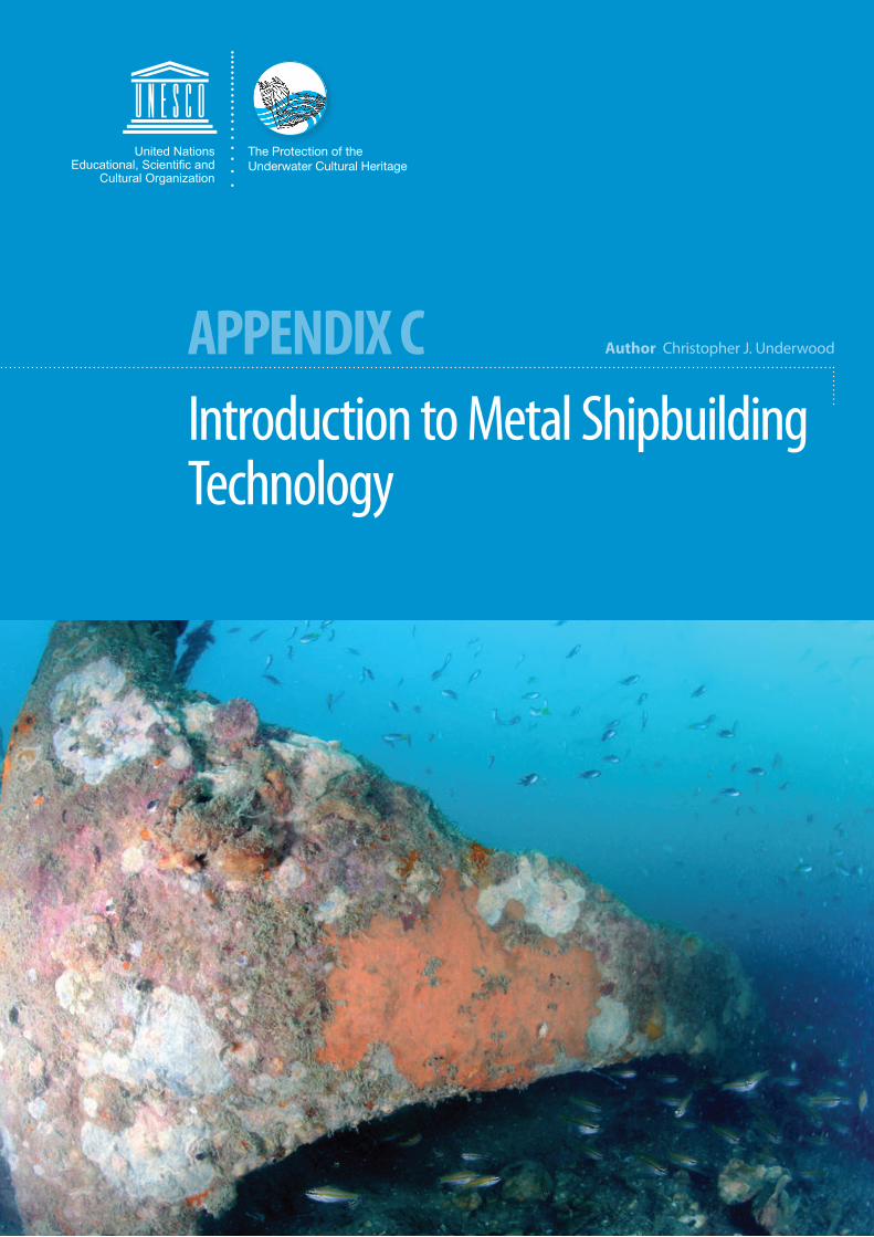
Bow: the forward part of a vessel’s hull.
Other ancillary parts of the ship and equipment asso-ciated with the bow include: the chain locker, anchors, anchor chain, hawse pipe(s), cargo derrick, capstan(s), windlass, and mooring bitts.
Forecastle: is often where the crew’s cabins are located and can be defined as the section of the deck that is forward of the foremast (if one is present).
Stem: the leading part of the bow. It is joined to the keel and rises to the forecastle.
Stern: the rear part of a nineteenth century vessel’s hull that includes the stern frame, steering gear, rudder and propeller.
Stern frame: consists of the rudder post, body post and connecting arch, with an extension for the connection to the keel.
As this appendix is part of the preparation for the fieldwork, it is impor-tant that trainers explain and illustrate to what extent components can be expected to survive in a typical wreck site. (See Additional Information 4)
Suggested Reading
Adams, J. 2001. Ships and Boats as Archaeological Source Material. World Archaeology, Vol. 32(3). Taylor and Francis Ltd, pp. 292-310.
Conlin, L. D. 1998. Ship Evolution, Ship ‘Ecology’ and the ‘Masked Value Hypothesis’. The International Journal of Nautical Archaeology. No.27, pp. 3-15.
Delgado, J.P. (ed.). 1997. Encyclopaedia of Underwater and Maritime Archaeol-ogy. London, British Museum Press.
Westerdahl, C. 1994. Maritime Cultures and Ship Types: Brief Comments on the Significance of Maritime Archaeology. The International Journal of Nautical Archaeology, Vol. 23.4, pp. 265-210.
2 Description of the Main Structural Fe atures
In relatively simple terms a ship can be considered a box that is strength-ened by numerous parts that join, brace or provide support. The strength of the box is dependent on each of these individual components, not-ing that some parts are more important than others in keeping the ves-sel afloat and is only as strong as its weakest component. (See Additional Information 5)
LEFT: The badly eroded bow section of the Mannok Island shipwreck. © UAD, Thailand
TOP RIGHT: The bow section of a late nineteenth century ves-sel’s hull. © Christopher J. Underwood
MIDDLE RIGHT: Stern of a nineteenth century vessel showing the stern frame arch and top of the rudder. © Christopher J. Underwood
RIGHT: Stern frame arch and the top part of the rudder on the Mannok Island shipwreck. © UAD, Thailand
ADDITIONAL INFORMATION
4 Deterioration of wreck material. The survival and rate of change is dependent on a number of factors:
• The length of time underwater
• Dynamic nature of the sinking
• Human impacts to the site, such as salvage and fishing
Combined with the site’s specific environmental characteristics, such as:
• Salinity• Temperature• Oxygenation• Light• Marine growth• Water movement • Burial by sediments
NB. This description is aimed at stating that ferrous metal objects will usually be more corroded and, therefore, are less easily recognizable than non-ferrous objects. It is not a detailed explanation of the physical, biological or chemical processes, which are covered in considerable depth in Unit 11: Finds Han-dling and Conservation.
5 The aim of a nautical architect is to design a vessel that is ‘fit for purpose’ and to be economical in the use of materials in its construction and conform to regulations.
Although the chain locker is below the deck, a capstan, mooring bollard (double bitt), anchor derrick and anchor can all be seen on the foredeck. © Christopher J. Underwood

6
Training Manual for the UNESCO Foundation Course on the Protection and Management of Underwater Cultural Heritage in Asia and the Pacific A P P E N D I X C I N T R O D U C T I O N TO M E TA L S H I P B U I L D I N G T E C H N O LO G Y
7
APPENDIx c
Other parts of the vessel and equipment associ-ated with stern include: the steering gear, pro-peller, capstan(s), windlass and mooring bitts.
Rudder: hangs on the stern frame by hinges which are formed by two parts, pintles and gudgeons. The weight of the rudder is nor-mally supported by the lower gudgeon.
Gudgeons: attached to the stern frame or can be cast or forged as an integral part of it.
Pintles: part of the rudder assembly.
Middle or midship: the remaining portion of the hull between the bow and stern sections. Usually a more rectangular box shape contain-ing components such as the cargo holds, fuel and water tanks, boilers, engine room. On the upper deck are located the cargo hatches, cargo winches, bridge and smaller fitings, such as scuppers (fittings that allow excess water to run off the decks) that often survive on shipwrecks.
Keel: is located along the exterior centre line of a vessel’s hull between the stem and stern frame. The keel can have a flat profile known as a flat keel plate or it can be a distinct rectangular shaped section, known as a bar keel.
Keelson: the corresponding reinforcement plate or beam that is located down the inte-rior centreline of the vessel between the stem and stern. The keelson is fixed to the transverse structural compo-nents, such as floors.
Floor(s): vertical plates that extend laterally across the vessel from the keelson to where the ship’s hull begins to form the side of the vessel, providing latitudinal strength to the structure.
Frame(s): formed from angle bars that rise upwards from the floors to the gunwhale (nor-mally the upper edge of the side of the vessel, on the upper deck). Frames are located along both sides of the vessel from stem to stern and are also commonly known as the ‘ribs’ of a vessel.
Side keelson(s): perform a similar function to the keelson, but are located parallel to the cen-tre keelson.
Bilge keelson(s): similar to side keelsons, but they curve upwards and inwards following the shape of the bow and stern.
Stringer(s): angle bar fixed along the interior lon-gitudinal axis of the vessel’s hull, usually riveted or welded to the frames.
Ship’s bridge. © Christopher J. Underwood
From left to right, ship’s navigation compass, ship’s wheel and telegraph. © Christopher J. Underwood
TOP: Floor section of a steamship wreck. © Christopher J. Underwood
MIDDLE: Frames and deck beams. © Christopher J. Underwood
LEFT: © Frames of the Mannok Island
Shipwreck site. © UAD, Thailand

8
Training Manual for the UNESCO Foundation Course on the Protection and Management of Underwater Cultural Heritage in Asia and the Pacific A P P E N D I X C I N T R O D U C T I O N TO M E TA L S H I P B U I L D I N G T E C H N O LO G Y
9
APPENDIx c
Deck beam(s): placed transversally across the vessel, they prevent the frames spreading out-wards and also support the decks. They are riv-eted or welded to the ship’s frames on the side of the vessel.
Beam knee(s): end section of a beam that allows it to be attached to the frame. They can be an integral part of the beam or as is the most com-mon method, a separate piece (built knee) that is riveted or welded to the beam and frame.
Deck(s): constructed from flat metal plates (or wooden planking) that lay over the beams. There can be one or more decks depending on the size and purpose of the vessel.
Pillar(s): hollow or solid vertical posts that pro-vide support for the deck(s). Where a central pil-lar is fitted, it will significantly increase the load capacity of the deck.
Bulkhead(s): longitudinal or transverse parti-tions that divide the vessel into compartments and can be made watertight to prevent flooding from spreading throughout a vessel.
Plating: forms the exterior shell of the hull, cab-ins partitions, decks and bulkheads. The plating is riveted or welded to structural components, such as frames and beams.
Riveting: the traditional method for joining the various components of metal ships prior to weld-ing. Most joints are made by overlapping plates to form a lap joint.
There is archaeological evidence of riveting that dates to the Bronze Age in the construction of daggers (See Useful Websites: Portable Antiqui-ties Scheme 2011).
Pillars supporting the main deck of the SS Sarmiento. © Christopher J. Underwood
Deck beams. © Christopher J. Underwood
Deck. © Christopher J. Underwood
ABOVE LEFT: Riveted hull construction. © Christopher J. Underwood
ABOVE MIDDLE: Riveting pattern of an overlapping hull plate joint. © Christopher J. Underwood
ABOVE RIGHT: Butt strap riveted joint of non-overlapping hull plates. © Christopher J. Underwood
RIGHT: Hull plating of the Mannok Island shipwreck. © UAD, Thailand
Deck beam end and beam plate on the Mannok Island shipwreck. © UAD, Thailand
Small section of a deck or walkway in the engine room of the Mannok Island shipwreck. © UAD, Thailand
Watertight bulkhead (across the beam of the vessel). © Christopher J. Underwood
10
Training Manual for the UNESCO Foundation Course on the Protection and Management of Underwater Cultural Heritage in Asia and the Pacific A P P E N D I X C I N T R O D U C T I O N TO M E TA L S H I P B U I L D I N G T E C H N O LO G Y
11
APPENDIx c
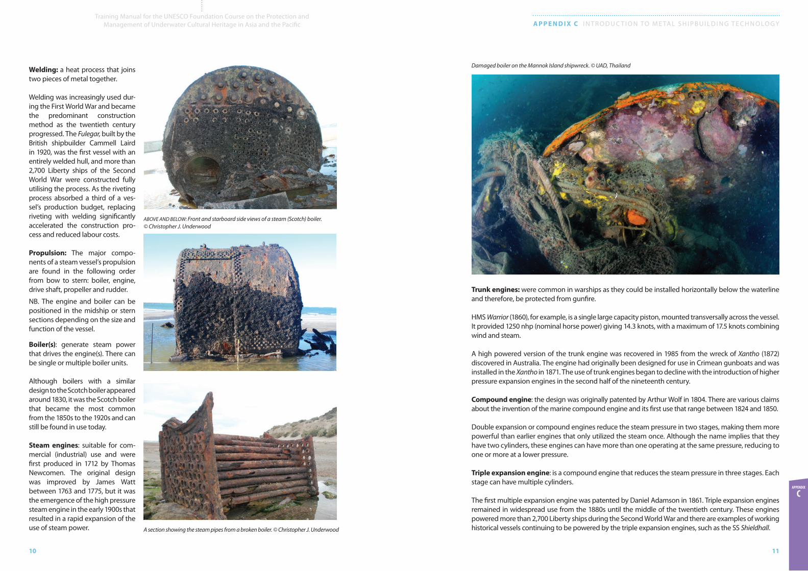
Trunk engines: were common in warships as they could be installed horizontally below the waterline and therefore, be protected from gunfire.
HMS Warrior (1860), for example, is a single large capacity piston, mounted transversally across the vessel. It provided 1250 nhp (nominal horse power) giving 14.3 knots, with a maximum of 17.5 knots combining wind and steam.
A high powered version of the trunk engine was recovered in 1985 from the wreck of Xantho (1872) discovered in Australia. The engine had originally been designed for use in Crimean gunboats and was installed in the Xantho in 1871. The use of trunk engines began to decline with the introduction of higher pressure expansion engines in the second half of the nineteenth century.
Compound engine: the design was originally patented by Arthur Wolf in 1804. There are various claims about the invention of the marine compound engine and its first use that range between 1824 and 1850.
Double expansion or compound engines reduce the steam pressure in two stages, making them more powerful than earlier engines that only utilized the steam once. Although the name implies that they have two cylinders, these engines can have more than one operating at the same pressure, reducing to one or more at a lower pressure.
Triple expansion engine: is a compound engine that reduces the steam pressure in three stages. Each stage can have multiple cylinders.
The first multiple expansion engine was patented by Daniel Adamson in 1861. Triple expansion engines remained in widespread use from the 1880s until the middle of the twentieth century. These engines powered more than 2,700 Liberty ships during the Second World War and there are examples of working historical vessels continuing to be powered by the triple expansion engines, such as the SS Shieldhall.
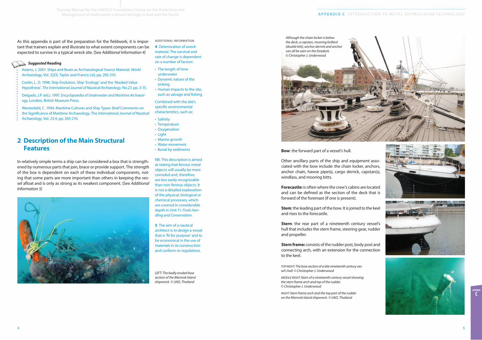
Welding: a heat process that joins two pieces of metal together.
Welding was increasingly used dur-ing the First World War and became the predominant construction method as the twentieth century progressed. The Fulegar, built by the British shipbuilder Cammell Laird in 1920, was the first vessel with an entirely welded hull, and more than 2,700 Liberty ships of the Second World War were constructed fully utilising the process. As the riveting process absorbed a third of a ves-sel’s production budget, replacing riveting with welding significantly accelerated the construction pro-cess and reduced labour costs.
Propulsion: The major compo-nents of a steam vessel’s propulsion are found in the following order from bow to stern: boiler, engine, drive shaft, propeller and rudder.
NB. The engine and boiler can be positioned in the midship or stern sections depending on the size and function of the vessel.
Boiler(s): generate steam power that drives the engine(s). There can be single or multiple boiler units.
Although boilers with a similar design to the Scotch boiler appeared around 1830, it was the Scotch boiler that became the most common from the 1850s to the 1920s and can still be found in use today.
Steam engines: suitable for com-mercial (industrial) use and were first produced in 1712 by Thomas Newcomen. The original design was improved by James Watt between 1763 and 1775, but it was the emergence of the high pressure steam engine in the early 1900s that resulted in a rapid expansion of the use of steam power.
Damaged boiler on the Mannok Island shipwreck. © UAD, Thailand
ABOVE AND BELOW: Front and starboard side views of a steam (Scotch) boiler. © Christopher J. Underwood
A section showing the steam pipes from a broken boiler. © Christopher J. Underwood
12
Training Manual for the UNESCO Foundation Course on the Protection and Management of Underwater Cultural Heritage in Asia and the Pacific A P P E N D I X C I N T R O D U C T I O N TO M E TA L S H I P B U I L D I N G T E C H N O LO G Y
13
APPENDIx c
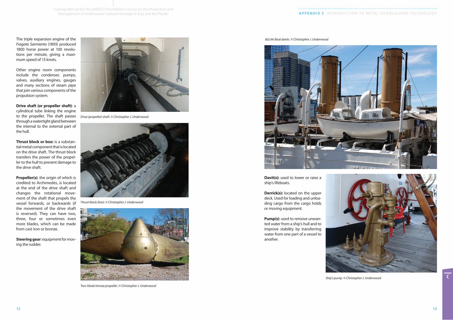
The triple expansion engine of the Fragata Sarmiento (1893) produced 1800 horse power at 100 revolu-tions per minute, giving a maxi-mum speed of 13 knots.
Other engine room components include the condenser, pumps, valves, auxiliary engines, gauges and many sections of steam pipe that join various components of the propulsion system.
Drive shaft (or propeller shaft): a cylindrical tube linking the engine to the propeller. The shaft passes through a watertight gland between the internal to the external part of the hull.
Thrust block or box: is a substan-tial metal component that is located on the drive shaft. The thrust block transfers the power of the propel-ler to the hull to prevent damage to the drive shaft.
Propeller(s): the origin of which is credited to Archimedes, is located at the end of the drive shaft and changes the rotational move-ment of the shaft that propels the vessel forwards, or backwards (if the movement of the drive shaft is reversed). They can have two, three, four or sometimes even more blades, which can be made from cast iron or bronze.
Steering gear: equipment for mov-ing the rudder.
Davit(s): used to lower or raise a ship’s lifeboats.
Derrick(s): located on the upper deck. Used for loading and unloa-ding cargo from the cargo holds or moving equipment.
Pump(s): used to remove unwan-ted water from a ship’s hull and to improve stability by transferring water from one part of a vessel to another.
BELOW: Boat davits. © Christopher J. Underwood
Thrust block (box). © C. J. Underwood
Drive (propeller) shaft. © Christopher J. Underwood
Thrust block (box). © Christopher J. Underwood
Two-blade bronze propeller. © Christopher J. Underwood
Ship’s pump. © Christopher J. Underwood
14
Training Manual for the UNESCO Foundation Course on the Protection and Management of Underwater Cultural Heritage in Asia and the Pacific A P P E N D I X C I N T R O D U C T I O N TO M E TA L S H I P B U I L D I N G T E C H N O LO G Y
15
APPENDIx c
Suggested Reading
Abbott, P. (ed.). 1917. Nautical Architecture. The Cambridge Technical Series. London, Cambridge University Press.
Bingeman, J.M., Bethell, J.P., Goodwing, P. and Mack, A. 2000. Copper and Other Sheathing in the Royal Navy. International Journal of Nautical Archaeology. No. 29.2, pp. 218-29.
Bingeman, J.M. 2010. The First HMS Invincible (1747-58): Her Excavations, 1980-1991. Oxbow Books.
Corlett, E. 1975. The Iron Ship: The Story of Brunel’s SS Great Britain. London, Conway.
Credland, A. 1982. Earles of Hull: Iron and Steel Shipbuilding on the Humber. City of Kingston upon Hull Museums and Art Galleries.
Curryer, N. B. 1999. Anchors: An Illustrated History. London, Chatham Publishing.
Garcia, R. and McCarthy, M. An Analysis of the Threads on the SS Xantho. Department of Western Australian Maritime Museum.
Goodwin, P. 1997. The Influence of Iron in Ship Construction: 1660 to 1830. Mariner’s Mirror. 84.1, pp. 26-40.
Johnston, P. and Robinson, D.S. 1993. The Wreck of the 1848 Propeller Indiana: Interim Report. International Journal of Nautical Archaeology, Vol. 22, 19-235.
McCarthy, M. 1988. SS. Xantho: The Pre-Disturbance, Assessment, Excavation and Management of an Iron Steam Shipwreck off the Coast of Western Australia. International Journal of Nautical Archaeology and Underwater Exploration, Vol. 17, pp. 339-347.
McCarthy, M. 1996. Ships Fastenings: a Preliminary Study Revisited. International Journal of Nautical Archaeology, Vol. 25, pp. 177-206.
McCarthy, M. 2001. Iron and Steamship Archaeology: Success and Failure on the SS Xantho. New York, Kluwer, Plenum.
McCarthy, M. 2005. Ship’s Fastenings: From Sewn Boat to Steamships. Texas A&M University Press.
Milne, G. McKewan, C. and Goodburn, D. 1998. Nautical Archaeology on the Foreshore: Hulk Recording on the Medway. Swindon. RCHM.
Molloy, E. 1943. Engineering Materials: Dealing with Ferrous and Non-ferrous Metals. London. George Newnes.
Nicol, G. 1937. Ship Construction and Calculations. Glasgow, Brown, Son and Ferguson.
Nordbok, A.B. 1975. The Lore of Ships, Revised Edition. Gothenburg, New Interlitho S.P.A.
Oertling, T.J. 1996. Ship’s Bilge Pumps: A History of their Development, 1500-1900. Texas A&M, University Press.
Paasch, H. 1997. Illustrated Marine Dictionary. London, Conway Maritime Press.
Quinn, P. 2003. Wrought Iron’s Suitability for Shipbuilding. Mariner’s Mirror. 89.4, pp. 437-61.
Reed, E.J. 2011. Shipbuilding in Iron and Steel: A Practical Treatise. New York, Cambridge University Press.
Reed, E.J. 2011. Our Iron-Clad Ships: Their Qualities, Performance and Cost. Cambridge Library Collections Technology.
Rees, G. 1971. Copper Sheathing: An Example of Technological Diffusion in the English Merchant Fleet. Journal of Transport History, Vol. 1, pp. 85-86.
Sawyer, L.A. and Mitchell, W.H. 1985. The Liberty Ships. The History and the ‘Emergency’ Type Cargo Ships Constructed in the United States during the Second World War. London, Lloyd’s of London Press.
Singer, C. et al, (eds.). 1978. A History of Technology, Volume III, From the Renaissance to the Industrial Revolution. Oxford, Clarendon Press.
Stammers, K. M. 2001. Iron Knees in Wooden Vessels: An Attempt at a Typology. International Journal of Nautical Archaeology. Elsevier Science. 30.1, pp. 115-121.
Staniforth, M. 1985. The Introduction and Use of Copper Sheathing, Including a Section Entitled: The Copper Sheathing and Fastenings of the American China Trader Rapid (1812). Bulletin of the Australian Institute for Maritime Archaeology. 9.1/2, pp. 21-48.
Stewart, I.G. 1992. Liberty Ships in Peacetime and their Contribution to World Shipping History. Rockingham. Marine Publications.
Stone, L. D. 1983. The Wreck Divers Guide to Sailing Ship Artefacts of the 19th Century. Underwater Archaeology Society of British Columbia. Vancouver, British Columbia.
Thearle, S. 1874. Naval Architecture: A Treatise on Laying Off and Building Wood, Iron and Composite Ships. London, William Collins and Sons.
Thearle, S. 1910. The Modern Practice of Ship-Building in Iron and Steel. William Collins and Sons.
Thiesen, W.H. 2003. Job 170 at Roach’s Shipyard, a Documented Sequence of Building an Iron Steamer. Nautical Research Journal. 48.3 (Fall), pp. 165-176.
Walton, T. 1992. Steel Ships: Their Construction and Maintenance. A Manual for Shipbuilders, Ship Superintendents, Students, and Marine Engineers, Second Edition. London, Charles Griffin.
Winton, T. 1992. Modern Steam Practice and Engineering: A Guide to Approved Methods of Construction and the Principles Relating Thereto. With Examples, Practical Rules and Formulae. London, Blackie and Sons.
Appendix Summary
It is important to recognize that this appendix is aimed at providing sufficient information to enable students to carry out an assessment of the wreck site that is then used in the development of a manage-ment plan. The additional information is provided to place the content in an archaeological or historical perspective and is not intended to be a detailed study of naval architecture.

16
Training Manual for the UNESCO Foundation Course on the Protection and Management of Underwater Cultural Heritage in Asia and the Pacific A P P E N D I X C I N T R O D U C T I O N TO M E TA L S H I P B U I L D I N G T E C H N O LO G Y
17
APPENDIx c
Suggested Timetable
The information provided by this appendix can be presented in three parts; two in the classroom prior to the diving project, with the third part during the fieldwork.
10 mins
Introduction to Metal Shipbuilding Technology
- The various factors that influence the design of vessels
- How vessels gradually evolved from wood to metal and from sail to steam in different geographic regions
40 mins
Part 1: Lecture
- Terminology and function of the main structural components of metal ships
- Terminology and function of the propulsion system of a metal steamship
- Terminology and function of deck fixtures and fittings
- Technical language concerning nautical terminology
- Demonstration of how a shipwreck can be identified by the study of its structure
- Discussion of how a metal shipwreck’s structural integrity will deteriorate at varying rates according to the site’s environmental conditions
- Illustration of the condition of structural components, fixtures and fittings that are commonly found on wreck sites
30 minsPart 2: Knowledge Review- Class participation session using an existing example drawing of a typical steamship.
Students will be asked to list out main features of the vessel from the drawing.
10 mins Concluding Remarks and Closure
Part 3: Practical Assistance to help students understand and interpret the various features found on the wreck site, provided as required during the field project.
Teaching Suggestions
The information on ship construction is kept at a generic level to avoid students becoming overwhelmed with the nautical terms and complexities of metal ship design.
Due to the commonality of many metal and wooden ship component names, trainers should highlight those parts of metal ships where there is overlap with wooden vessels introduced in Unit 14: Asian Shipbuilding Technology and its appendices
Useful Websites
• HMS Victory: www.hms-victory.com (Accessed November 2011.)
• HMS Warrior: www.hmswarrior.org (Accessed November 2011.)
• Liberty Ship Jeromiah O’Brien: www.ssjeremiahobrien.org (Accessed November 2011.)
• Portable Antiquities Scheme: use of riveting during the Bronze Age finds.org.uk/database/artefacts/record/id/276077 (Accessed November 2011.)
• SS Xantho: museum.wa.gov.au/broadhurst/xantho-Shipwreck (Accessed November 2011.)
• SS Shieldhall: www.ss-shieldhall.co.uk/Shieldhall/Technical.html (Accessed November 2011.)
18
Training Manual for the UNESCO Foundation Course on the Protection and Management of Underwater Cultural Heritage in Asia and the Pacific A P P E N D I X C I N T R O D U C T I O N TO M E TA L S H I P B U I L D I N G T E C H N O LO G Y
19
APPENDIx c
Suggested Reading: Full List
Abbott, P. (ed.). 1917. Nautical Architecture. The Cambridge Technical Series. London, Cambridge University Press.
Adams, J. 2001. Ships and Boats as Archaeological Source Material. World Archaeology, Vol. 32(3). Taylor and Francis Ltd, pp. 292-310.
Bingeman, J.M., Bethell, J.P., Goodwing, P. and Mack, A. 2000. Copper and Other Sheathing in the Royal Navy. International Journal of Nautical Archaeology. No. 29.2, pp. 218-29.
Bingeman, J.M. 2010. The First HMS Invincible (1747-58): Her Excavations, 1980-1991. Oxbow Books.
Conlin, L. D. 1998. Ship Evolution, Ship ‘Ecology’, and the ‘Masked Value Hypothesis’. The International Journal of Nautical Archaeology. No.27, pp. 3-15.
Corlett, E. 1975. The Iron Ship: The Story of Brunel’s SS Great Britain. London, Conway.
Credland, A. 1982. Earles of Hull: Iron and Steel Shipbuilding on the Humber. City of Kingston upon Hull Museums and Art Galleries.
Curryer, N. B. 1999. Anchors: An Illustrated History. London, Chatham Publishing.
Delgado, J.P. (ed.). 1997. Encyclopaedia of Underwater and Maritime Archaeology. London, British Museum Press.
Garcia, R. and McCarthy, M. An Analysis of the Threads on the SS Xantho. Department of Western Australian Maritime Museum.
Goodwin, P. 1997. The Influence of Iron in Ship Construction: 1660 to 1830. Mariner’s Mirror. 84.1, pp. 26-40.
Johnston, P. and Robinson, D.S. 1993. The Wreck of the 1848 Propeller Indiana: Interim Report. International Journal of Nautical Archaeology, Vol. 22, pp. 19-235.
McCarthy, M. 1988. SS. Xantho: The Pre-Disturbance, Assessment, Excavation and Management of an Iron Steam Shipwreck off the Coast of Western Australia. International Journal of Nautical Archaeology and Underwater Exploration, Vol. 17, pp. 339-347.
McCarthy, M. 1996. Ships Fastenings: a Preliminary Study Revisited. International Journal of Nautical Archaeology, Vol. 25, pp. 177-206.
McCarthy, M. 2001. Iron and Steamship Archaeology: Success and Failure on the SS Xantho. New York, Kluwer, Plenum.
McCarthy, M. 2005. Ship’s Fastenings: From Sewn Boat to Steamships. Texas A&M University Press.
Milne, G. McKewan, C. and Goodburn, D. 1998. Nautical Archaeology on the Foreshore: Hulk Recording on the Medway. Swindon. RCHM.
Molloy, E. Engineering Materials: Dealing with Ferrous and Non-ferrous Metals. London, George Newnes.
Molloy, E. 1943. Engineering Materials: Dealing with Ferrous and Non-ferrous Metals. London, George Newnes.
Nicol, G. 1937. Ship Construction and Calculations. Glasgow, Brown, Son and Ferguson.
Nordbok, A.B. 1975. The Lore of Ships, Revised Edition. Gothenburg, New Interlitho S.P.A.
Oertling, T.J. 1996. Ship’s Bilge Pumps: A History of their Development, 1500-1900. Texas A&M University Press.
Paasch, H. 1997. Illustrated Marine Dictionary. London, Conway Maritime Press.
Quinn, P. 2003. Wrought Iron’s Suitability for Shipbuilding. Mariner’s Mirror. 89.4, pp. 437-61.
Reed, E.J. 2011. Shipbuilding in Iron and Steel: A Practical Treatise. New York, Cambridge University Press.
Reed, E.J. 2011. Our Iron-Clad Ships: Their Qualities, Performance and Cost. Cambridge Library Collections Technology.
Rees, G. 1971. Copper Sheathing: An Example of Technological Diffusion in the English Merchant Fleet. Journal of Transport History, Vol.1, pp. 85-86.
Sawyer, L.A. and Mitchell, W.H. 1985. The Liberty Ships. The History and the ‘Emergency’ Type Cargo Ships Constructed in the United States during the Second World War. London, Lloyd’s of London Press.
Singer, C. et al, (eds.). 1978. A History of Technology, Volume III, From the Renaissance to the Industrial Revolution. Oxford, Clarendon Press.
Stammers, K. M. 2001. Iron Knees in Wooden Vessels: An Attempt at a Typology. International Journal of Nautical Archaeology. Elsevier Science. 30.1, pp. 115-121.
Staniforth, M. 1985. The Introduction and Use of Copper Sheathing, Including a Section Entitled: The Copper Sheathing and Fastenings of the American China Trader Rapid (1812). Bulletin of the Australian Institute for Maritime Archaeology. 9.1/2, pp. 21-48.
Stewart, I.G. 1992. Liberty Ships in Peacetime and their Contribution to World Shipping History. Rockingham, Marine Publications.
Stone, L. D. 1983. The Wreck Divers Guide to Sailing Ship Artefacts of the 19th Century. Underwater Archaeology Society of British Columbia. Vancouver, British Columbia.
Thearle, S. 1874. Naval Architecture: A Treatise on Laying Off and Building Wood, Iron and Composite Ships. London, William Collins and Sons.
Thearle, S. 1910. The Modern Practice of Ship Building in Iron and Steel. William Collins and Sons.
Thiesen, W.H. 2003. Job 170 at Roach’s Shipyard, a Documented Sequence of Building an Iron Steamer. Nautical Research Journal. 48.3 (Fall), pp. 165-176.
Walton, T. 1992. Steel Ships: Their Construction and Maintenance. A Manual for Shipbuilders, Ship Superintendents, Students, and Marine Engineers, Second Edition. London, Charles Griffin.
Westerdahl, C. 1994. Maritime Cultures and Ship Types: Brief Comments on the Significance of Maritime Archaeology. The International Journal of Nautical Archaeology, Vol. 23.4, pp. 265-210.
Winton, T. 1992. Modern Steam Practice and Engineering: A Guide to Approved Methods of Construction and the Principles Relating Thereto. With Examples, Practical Rules and Formulae. London, Blackie and Sons.