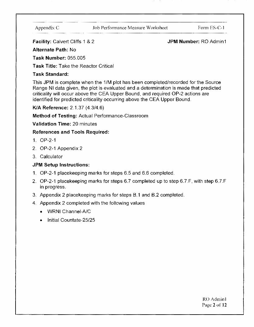
· Appendix C Job Performance Measure Worksheet Facility: Calvert Cliffs 1 & 2 Alternate Path: No...
384
Examinee: ----- Calvert Cliffs Nuclear Power Plant 2018 NRC Initial Licensed Operator Exam JPM-RO Admin1
Transcript of · Appendix C Job Performance Measure Worksheet Facility: Calvert Cliffs 1 & 2 Alternate Path: No...

Examinee: -----
Calvert Cliffs Nuclear Power Plant
2018 NRC Initial Licensed Operator Exam
JPM-RO Admin1
Appendix C Job Performance Measure Worksheet
Facility: Calvert Cliffs 1 & 2
Alternate Path: No
Task Number: 055.005
Task Title: Take the Reactor Critical
Task Standard:
Form ES-C-1
JPM Number: RO Admin1
This JPM is complete when the 1/M plot has been completed/recorded for the Source Range NI data given, the plot is evaluated and a determination is made that predicted criticality will occur above the CEA Upper Bound, and required OP-2 actions are identified for predicted criticality occurring above the CEA Upper Bound.
K/A Reference: 2.1.37 (4.3/4.6)
Method of Testing: Actual Performance-Classroom
Validation Time: 20 minutes
References and Tools Required:
1. OP-2-1
2. OP-2-1 Appendix 2
3. Calculator
JPM Setup Instructions:
1. OP-2-1 placekeeping marks for steps 6.5 and 6.6 completed.
2. OP-2-1 placekeeping marks for steps 6.7 completed up to step 6.7.F, with step 6.7.F in progress.
3. Appendix 2 placekeeping marks for steps B.1 and B.2 completed.
4. Appendix 2 completed with the following values
• WRNI Channel-A/C
• Initial Countate-25/25
RO Adminl Page 2 of 12

Appendix C Job Performance Measure Worksheet Form ES-C-1
Directions to the Examinee:
I will explain the initial conditions, which steps to simulate or discuss, and provide initiating cues. When you complete the task successfully, the objective for this job performance measure will be satisfied.
Hand Examinee's Cue Sheet to Examinee at this time.
Initial Conditions:
1. You are performing the duties of an extra RO.
2. Unit-1 Reactor tripped 4 days ago.
3. 1/M is the only available reactivity monitoring method due to PPG 1/M Application and SUR Monitor issues.
4. RCS boron sample is within 1 PPM of ECG boron concentration.
5. ECG is Group 4 at 90".
6. ECG CEA Lower Bound is Group 4 at 16".
7. ECG CEA Upper Bound is Group 5 at 59.25".
8. Reactor Startup is in progress per OP-2.
9. Base countrate, CR1, was 25 CPS.
Initiating Cue:
1. The Unit Supervisor assigns you three tasks:
Task 1
Complete the 1/M plot, given the following data table, for each CEA position as the CEAs were/are being withdrawn.
CEA Position WRNI-A (CPS)
Reg Group 1- O" 25
Reg Group 1 - 95.25" 31
Reg Group 2 - 108.75" 42
Reg Group 3 - 122.5" 63
Reg Group 4 - 81.5" 80
Reg Group 5 - 54.5" 125
WRNI-C (CPS)
25
31
42
63
80
125
RO Adminl Page 3 of 12
Appendix C Job Performance Measure Worksheet Form ES-C-1
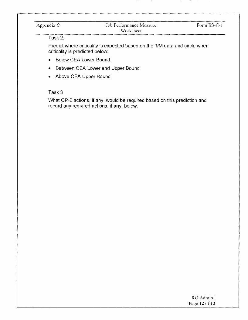
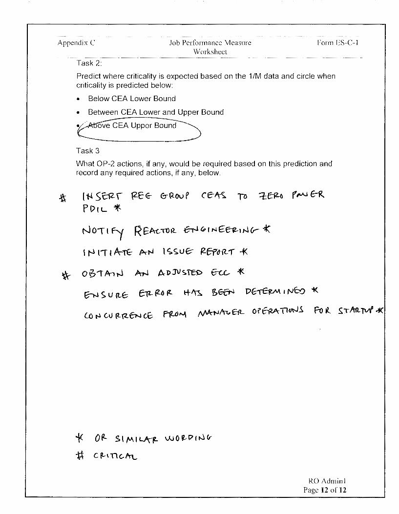
Task 2:
Predict where criticality is expected based on the 1/M data and circle when criticality is predicted below:
• Below CEA Lower Bound
• Between CEA Lower and Upper Bound
• Above CEA Upper Bound
Task 3
What OP-2 actions, if any, would be required based on this prediction and record any required actions, if any, below.
2. Are there any questions? You may begin.
RO Adminl Page 4 of 12

Appendix C Job Performance Measure Worksheet Form ES-C-1
1--
STEP STANDARD 1-- <( ELEMENT <( en
en z ::::>
TIME START:
CUE After Examinee reviews Cue Sheet, provide a calculator, the partially completed OP-2-1, and the partially completed OP-2-1 Appendix 2.
Examiner NOTE
The following addresses Task 1 from the Cue Sheet.
APP 1/M METHOD OF REACTIVITY Identifies next step to
2 MONITORING complete is Appendix 2 based - -on Examinee Cue Sheet.
Comment
Examiner NOTE
If a data point is not calculated and/or plotted, the Critical Step can be considered met if a trend line drawn through the 1/M plot would have intersected the data point(s) not specifically calculated by the Examinee.
RO Adminl Page 5 of 12
Appendix C Job Performance Measure Worksheet Form ES-C-1
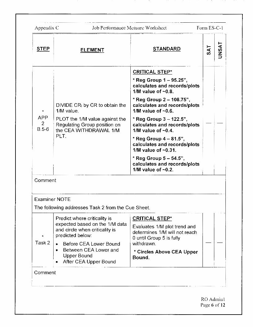
STEP ELEMENT STANDARD
CRITICAL STEP*
! * Reg Group 1 - 95.25",
! calculates and records/plots 1/M value of-0.8.
* Reg Group 2 -108.75", DIVIDE CR1 by CR to obtain the calculates and records/plots
* 1/M value. 1/M value of -0.6. APP PLOT the 1 /M value against the * Reg Group 3 - 122.5",
2 Regulating Group position on calculates and records/plots B.5-6 the CEA WITHDRAWAL 1/M 1/M value of -0.4.
PLT. * Reg Group 4 - 81.5", calculates and records/plots 1/M value of -0.31.
* Reg Group 5 - 54.5", calculates and records/plots 1/M value of -0.2.
Comment
Examiner NOTE
The following addresses Task 2 from the Cue Sheet.
Predict where criticality is CRITICAL STEP* expected based on the 1 /M data Evaluates 1/M plot trend and and circle when criticality is determines 1 /M will not reach
* predicted below: 0 until Group 5 is fully Task 2 • Before CEA Lower Bound withdrawn.
• Between CEA Lower and * Circles Above CEA Upper Upper Bound Bound.
• After CEA Upper Bound
Comment
I-I- <{ <{ en en z
::J
- -
- -
RO Adminl Page 6 of 12
Appendix C Job Performance Measure Worksheet Form ES-C-1
STEP ELEMENT STANDARD
Examiner NOTE
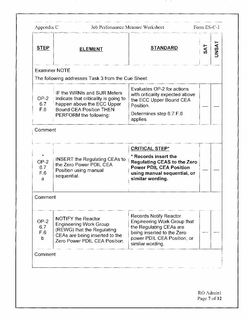
The following addresses Task 3 from the Cue Sheet.
OP-2 6.7 F.6
IF the WRNls and SUR Meters indicate that criticality is going to happen above the ECC Upper Bound CEA Position THEN PERFORM the following:
Comment
* OP-2 6.7 F.6 a
INSERT the Regulating CEAs to the Zero Power PDIL CEA Position using manual sequential.
Comment
OP-2 6.7 F.6 b
NOTIFY the Reactor Engineering Work Group (REWG) that the Regulating CEAs are being inserted to the Zero Power PDIL CEA Position.
Comment
Evaluates OP-2 for actions with criticality expected above the ECC Upper Bound CEA Position.
Determines step 6.7.F.6 applies.
CRITICAL STEP*
* Records insert the Regulating CEAS to the Zero Power POil CEA Position using manual sequential, or similar wording.
Records Notify Reactor Engineering Work Group that the Regulating CEAs are being inserted to the Zero power PDIL CEA Position, or similar wording.
1--1-- <( <( U'J U'J z
:::,
RO Adminl Page 7 of 12

Appendix C Job Performance Measure Worksheet Form ES-C-1
STEP ELEMENT
OP-2 ' INITIATE and Issue Report to 6.7
F.6 j document any ECC
C discrepancy.
Comment
* OP-2
OBTAN an adjusted ECC from 6.7 REWG PER NEOP-302. F.6
d
Comment
STANDARD
Records Initiate an Issue Report, or similar wording.
CRITICAL STEP*
*Records obtain an adjusted ECC from REWG per NEOP-302, or similar wording.
r r <( <( en en z
::J
- -
- -
RO Adminl Page 8 of 12
Appendix C Job Performance Measure Worksheet Form ES-C-1
STEP
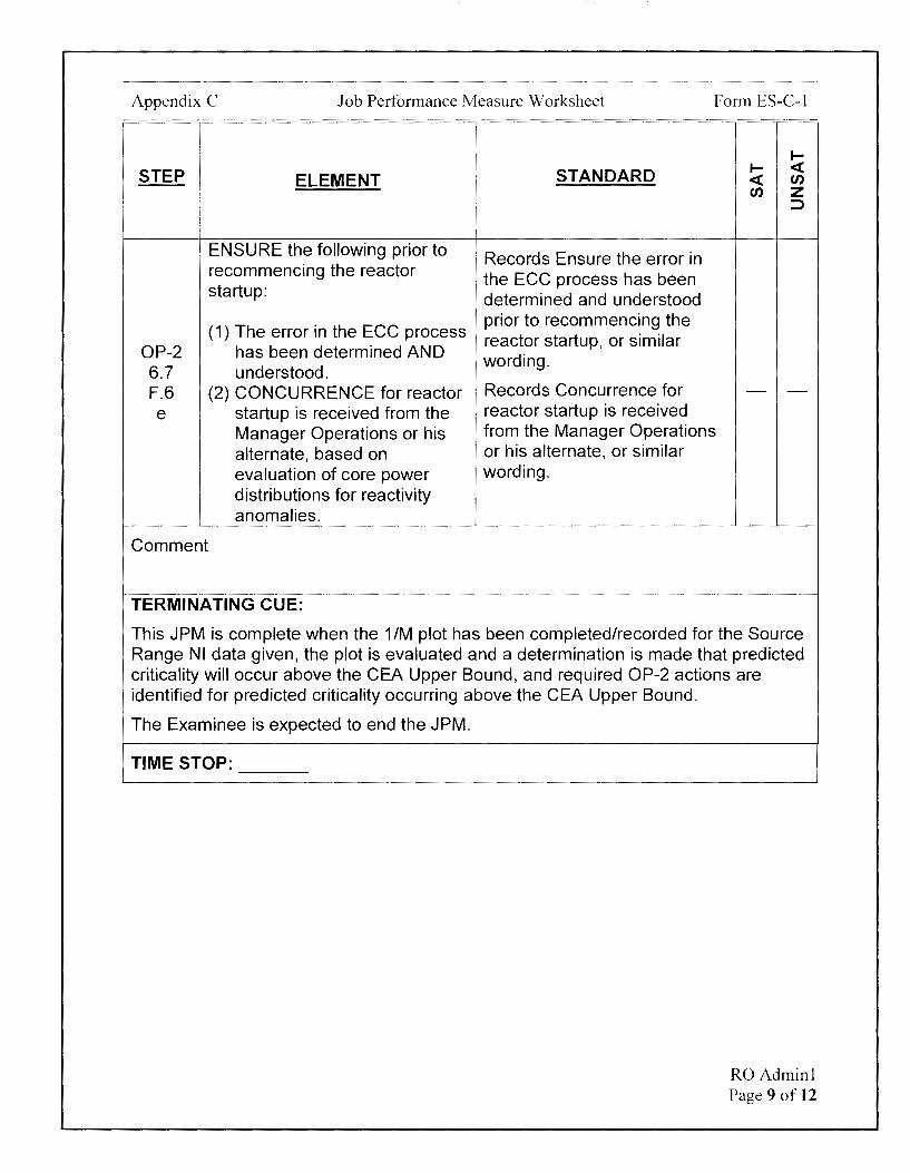
OP-2 6.7 F.6 e
Comment
ELEMENT
ENSURE the following prior to recommencing the reactor startup:
(1) The error in the ECC process has been determined AND understood.
(2) CONCURRENCE for reactor startup is received from the Manager Operations or his alternate, based on evaluation of core power distributions for reactivity anomalies.
TERMINATING CUE:
STANDARD
Records Ensure the error in the ECC process has been determined and understood prior to recommencing the reactor startup, or similar wording.
Records Concurrence for reactor startup is received from the Manager Operations or his alternate, or similar wording.
I<( f/)
I<( f/) z :J
This JPM is complete when the 1/M plot has been completed/recorded for the Source Range NI data given, the plot is evaluated and a determination is made that predicted criticality will occur above the CEA Upper Bound, and required OP-2 actions are identified for predicted criticality occurring above the CEA Upper Bound.
The Examinee is expected to end the JPM.
TIME STOP: ---
RO Adminl Page 9 of 12
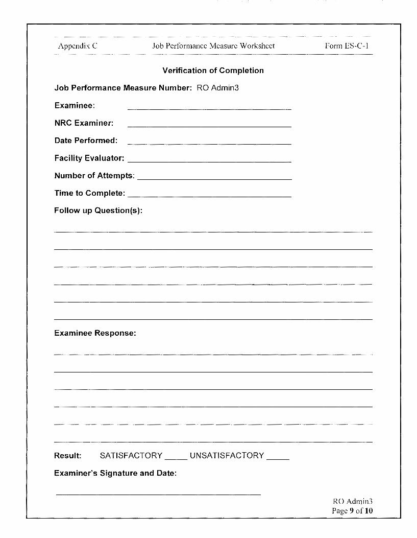
Appendix C Job Performance Measure Worksheet
Verification of Completion
Job Performance Measure Number: RO Admin1
Examinee:
NRC Examiner:
Date Performed:
Facility Evaluator: ________________ _
Number of Attempts: _______________ _
Time to Complete: ________________ _
Follow up Question(s):
Examinee Response:
Result: SATISFACTORY UNSATISFACTORY -- --
Examiner's Signature and Date:
Form ES-C-1
RO Adminl Page 10 of 12

Appendix C
Initial Conditions:
Job Performance Measure Worksheet
EXAMINEE'S CUE SHEET
1. You are performing the duties of an extra RO.
2. Unit-1 Reactor tripped 4 days ago.
Form ES-C-1
3. 1/M is the only available reactivity monitoring method due to PPC 1/M Application and SUR Monitor issues.
4. RCS boron sample is within 1 PPM of ECC boron concentration.
5. ECC is Group 4 at 90".
6. ECC CEA Lower Bound is Group 4 at 16".
7. ECC CEA Upper Bound is Group 5 at 59.25".
8. Reactor Startup is in progress per OP-2.
9. Base countrate, CR1, was 25 CPS.
Initiating Cue:
1. The Unit Supervisor assigns you three tasks:
Task 1
Complete the 1/M plot, given the following data table, for each CEA position as the CEAs were/are being withdrawn.
CEA Position WRNI-A (CPS)
Reg Group 1- O" 25
Reg Group 1 - 95.25" 31
Reg Group 2- 42 108.75"
Reg Group 3 - 122.5" 63
Reg Group 4 - 81.5" 80
Reg Group 5 - 54.5" 125
Cue continued on next page
WRNI-C (CPS)
25
31
42
63
80
125
RO Adminl Page 11 of 12
Appendix C
Task 2:
Job Performance Measure Worksheet
Form ES-C-1
Predict where criticality is expected based on the 1 /M data and circle when criticality is predicted below:
• Below CEA Lower Bound
• Between CEA Lower and Upper Bound
• Above CEA Upper Bound
Task 3
What OP-2 actions, if any, would be required based on this prediction and record any required actions, if any, below.
RO Adminl Page 12 of 12

1/M 1.0
0.9
0.8
0.7
0.6
0.5
0.4
0.3
0.2
0.1
0.0
PLANT STARTUP FROM HOT STANDBY TO MINIMUM LOAD
OP-2 APPENDIX 2 Rev. 05000/Unit 1 Page 4 of 4
1/M METHOD OF REACTIVITY MONITORING [80032)
CEA WITHDRAWAL 1/M PLOT
A: C WRNI Channel_!_
f"l' , Initial Countrate !!"___':::, I}-)_
~ '-
'"'-V"\4 ...... .( ;7 • ;). .. , ~ I
c,r....
"' 7) 0{,
" ~ ?..1 ~s, l.tl-r'\
L P'.... '- ~"' l1, .s i 1;
N""\ )
c,i...
l'1< ) -· _. I - ..... ' --" :/'f, 'ii) ' <'
r-:J
~t. ), <is'<> l"'-t ' \. ~
' "' I 1 I I 3 I I I I 5 I <
0 54.4 108.8 0 54.4 108.8 0 54.4 108.8 27.2 81.6 136 27.2 81.6 136 27.2 81.6 136
I I 2 I I I 4 I 0 54.4 108.8 0 54.4 108.8
27.2 81.6 136 27.2 81.6 136
CEA WITHDRAWAL (INCHES)
Appendix C
Task 2:
Job Perfonnance Measure Worksheet
Form ES-C-1
Predict where criticality is expected based on the 1/M data and circle when criticality is predicted below:
• Below CEA Lower Bound
• Between CEA Lower and Upper Bound
ove CEA Upper Bound
Task 3
What OP-2 actions, if any, would be required based on this prediction and record any required actions, if any, below.
(1'lSc12-, {2.EE- <:r~0uP ce-~ n> -=t.~ r/lAJ&R PDlL '* N o-r , ry Rf Ac. TO,~ e,-.i (;, , r,.1 E E1?--, N (,.- -t
l ~ l 1" I A-i'E- A-rJ \ <;. 5. U E;- 12.tfo R "f 1<
\\-- o ~, A. .J ArJ AD JV s. t6:> £-u.... « ~ s V (LE; e,z.. (<.O (l. tt'n.. 1>66'-I D~ I tvt0 1(
(0 ~ C-v l?-~ f-N cf; F(Ll> ~ f\!,ktJl'rv 8L Of~ Tl ~1 Fo at S -r-lt1t:rvf .)}(
i( 0 p_ $ l fJ" LJ\"'fZ. W O lt- r,> I ~ Cr
-:t:\: C (L \ TI C- Ai_
RO Adminl Page 12 of 12

Examinee:
Calvert Cliffs Nuclear Power Plant
2018 NRC Initial Licensed Operator Exam
JPM-RO Admin2
Appendix C Job Performance Measure Worksheet
Facility: Calvert Cliffs 1 & 2
Alternate Path: No
Task Number: 201.005
Task Title: Evaluate the need for plant cooldown
Task Standard:
Form ES-C-1
JPM Number: RO Admin2
This JPM is complete when available condensate inventory is evaluated using EOP Attachment (9), and it is determined there is insufficient water to cooldown to< 300° F and the plant could be maintained in hot standby conditions for 3 days from the trip.
K/A Reference: 2.1.25 (3.9/4.2)
Method of Testing: Actual Performance-Classroom
Validation Time: 7 minutes
References and Tools Required:
1. EOP Attachment (9)
2. Calculator
JPM Setup Instructions:
1. N/A
RO Admin2 Page 2 of 13
Appendix C Job Performance Measure Worksheet Form ES-C-1
Directions to the Examinee:
I will explain the initial conditions, which steps to simulate or discuss, and provide initiating cues. When you complete the task successfully, the objective for this job performance measure will be satisfied.
Hand Examinee's Cue Sheet to Examinee at this time.
Initial Conditions:
1. You are performing the duties of the Unit-2 CRO.
2. Unit-2 is operating at 100% power when a Station Blackout occurs.
3. EOP-7-2, Station Blackout, is implemented.
4. The need for a Unit-2 plant cooldown is being evaluated with the following current conditions:
• Unit-1 is in Mode 6
• Unit-2 tripped 2 hours ago.
• Unit-2 is in Hot Standby
• The TBVs are not available
• 21 CST level is 30'
• 12 CST level is 24.5'
• 11 CST is empty for maintenance
Initiating Cue:
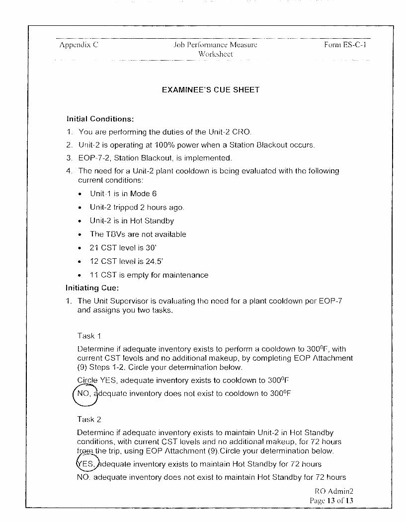
1. The Unit Supervisor is evaluating the need for a plant cooldown per EOP-7 and assigns you two tasks.
Task 1
Determine if adequate inventory exists to perform a cooldown to 300°F, with current CST levels and no additional makeup, by completing EOP Attachment (9) Steps 1-2. Circle your determination below.
Circle YES, adequate inventory exists to cooldown to 300°F
NO, adequate inventory does not exist to cooldown to 300°F
Task 2
Determine if adequate inventory exists to maintain Unit-2 in Hot Standby conditions, with current CST levels and no additional makeup, for 72 hours from the trip, using EOP Attachment (9).Circle your determination below.
YES, adequate inventory exists to maintain Hot Standby for 72 hours
NO, adequate inventory does not exist to maintain Hot Standby for 72 hours
RO Admin2 Page 3 of 13

Appendix C Job Performance Measure Worksheet
2. Are there any questions? You may begin.
Form ES-C-1
RO Admin2 Page 4 of 13
Appendix C Job Performance Measure Worksheet Form ES-C-1
1--
STEP STANDARD 1-- <( ELEMENT <( en
en z ::::,
TIME START:
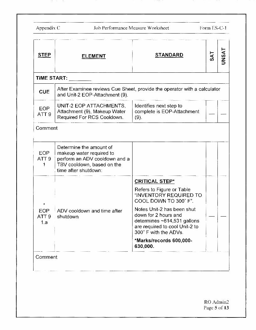
CUE After Examinee reviews Cue Sheet, provide the operator with a calculator and Unit-2 EOP-Attachment (9).
EOP UNIT-2 EOP ATTACHMENTS,
ATT9 Attachment (9), Makeup Water Required For RCS Cooldown.
Comment
Determine the amount of EOP makeup water required to
ATT9 perform an ADV cooldown and a 1 TBV cooldown, based on the
time after shutdown:
*
EOP ADV cooldown and time after ATT9 shutdown
1.a
Comment
Identifies next step to complete is EOP-Attachment (9).
CRITICAL STEP*
Refers to Figure or Table "INVENTORY REQUIRED TO COOL DOWN TO 300° F".
Notes Unit-2 has been shut down for 2 hours and determines -614,531 gallons are required to cool Unit-2 to 300° F with the ADVs.
*Marks/records 600,000-630,000.
- -
- -
RO Admin2 Page 5 of 13

Appendix C Job Performance Measure Worksheet Form ES-C-1
STEP ELEMENT
EOP ATT9
TBV cooldown and time after shutdown
1.b
Comment
EOP Determine the amount of ATT9 makeup water available in the
2 CSTs:
* EOP
Record the level in 21 CST. ATT9
2.a
Comment
* EOP
Record the level in 12 CST. ATT9
2.b
Comment
STANDARD
Refers to Figure or Table "INVENTORY REQUIRED TO COOL DOWN TO 300° F".
Notes Unit-2 has been shut down for 2 hours and determines -88,490 gallons are required to cool Unit-2 to 300° F with the TBVs.
Marks/records 83,000-93,000 or N/A.
CRITICAL STEP*
*Records 21 CST level as 30 ft.
CRITICAL STEP*
*Records 12 CST level as 24.5 ft.
I-I- <{ <{ en en z
::::>
- -
- -
- -
RO Admin2 Page 6 of 13

Appendix C Job Performance Measure Worksheet
STEP ELEMENT STANDARD
* CRITICAL STEP* EOP
Record the level in 11 CST. ATT9 *Records 11 CST level as 0
2.c ft.
Comment
EOP Determine the status of Unit-1
ATT9 2.d
(check one):
Evaluates Unit-1 condition EOP
Mode 1, 2 or 3 and does NOT from Examinee Cue Sheet. ATT9
require AFW operation. Determines Unit-1 is not in 2.d (1) Mode 1-3.
Comment
Evaluates Unit-1 condition EOP
Mode 1, 2 or 3 and does require from Examinee Cue Sheet. ATT9
AFW operation. Determines Unit-1 is not in 2.d (2) Mode 1-3.
Comment
CRITICAL STEP*
* Evaluates Unit-1 condition
EOP from Examinee Cue Sheet.
ATT9 Mode 4, 5, 6 or defueled. *Determines condition is
2.d (3) applicable and checks/marks 2.d.(3) as Unit-1 current condition.
Comment
Form ES-C-1
I-I- <( <( en en z
:::,
- -
- -
- -
- -
RO Admin2 Page 7 of 13
Appendix C Job Performance Measure Worksheet Form ES-C-1
I-
STANDARD I- <( STEP ELEMENT <( ff)
ff) z ::>
EOP ATT9
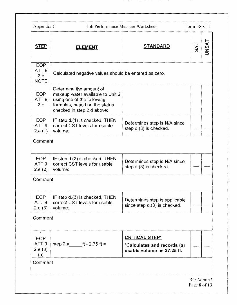
Calculated negative values should be entered as zero. 2.e
NOTE
Determine the amount of EOP makeup water available to Unit 2
ATT9 using one of the following 2.e formulas, based on the status
checked in step 2.d above:
EOP IF step d.(1) is checked, THEN Determines step is NIA since
ATT9 correct CST levels for usable step d.(3) is checked. - -
2.e (1) volume:
Comment
EOP i 1F step d.(2) is checked, THEN Determines step is N/A since
ATT9 correct CST levels for usable step d.(3) is checked. - -
2.e (2) , volume: i
Comment
EOP IF step d.(3) is checked, THEN Determines step is applicable
ATT9 correct CST levels for usable 2.e (3) volume:
Comment
* EOP
ATT9 step 2.a 2.e (3)
(a)
Comment
since step d.(3) is checked.
CRITICAL STEP* ft - 2.75 ft= *Calculates and records (a)
usable volume as 27 .25 ft.
- -
- -
RO Admm2 Page 8 of 13

Appendix C Job Performance Measure Worksheet Form ES-C-1
STEP ELEMENT
* EOP
ATT9 step 2.b ft-2.5ft= 2.e (3)
(b)
Comment
* EOP
ATT9 step 2.c ft - 2.75 ft= 2.e (3)
(c)
Comment
* EOP
step(a) ft+ step(b) ATT9
ft+ step(c) ft = 2.e (3)
(d)
Comment
* Convert the amount of CST level EOP into gallons.
ATT9 (ft available) ft X 9636.78 2.e (3)
(f) gal/ft=
Comment
STANDARD
CRITICAL STEP*
*Calculates and records (b) usable volume as 22 ft.
CRITICAL STEP*
* Calculates and records (b) usable volume as O ft.
CRITICAL STEP*
* Calculates and records e.(3) usable volume as 49.25 ft.
CRITICAL STEP*
* Calculates and records 2.f gallons available between 474,573-474,622 gals.
~ ~ <t <t en en z
:::)
- -
- -
- -
- -
RO Admin2 Page 9 of 13
Appendix C Job Performance Measure Worksheet Form ES-C-1
STEP ELEMENT
Examiner NOTE
The following addresses Task 1.
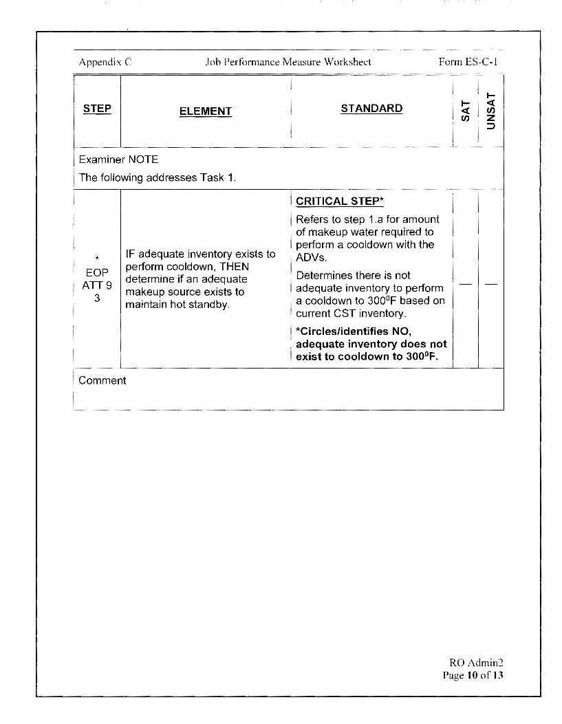
* IF adequate inventory exists to
EOP perform cooldown, THEN determine if an adequate
ATT9 3
makeup source exists to maintain hot standby.
I
Comment
t-
STANDARD t- <( <( u, u, z
:::>
CRITICAL STEP*
Refers to step 1.a for amount of makeup water required to perform a cooldown with the ADVs.
Determines there is not adequate inventory to perform - -
a cooldown to 300°F based on current CST inventory.
*Circles/identifies NO, adequate inventory does not exist to cool down to 300°F.
RO Admin2 Page 10 of 13

Appendix C Job Performance Measure Worksheet Form ES-C-1
STEP ELEMENT
Examiner NOTE
The following addresses Task 2.
* EOP
ATT9 4
I
IF adequate inventory does NOT exist to perform cooldown, THEN evaluate the following:
• Maintaining hot standby conditions
Comment
TERMINATING CUE:
STANDARD
CRITICAL STEP*
Refers to Figure or Table "MAKEUP WATER REQUIRED TO MAINTAIN HOT STANDBY".
Determines - 450,000 gallons are required to maintain Unit-2 in Hot Standby for 3 days (72 hours).
*Circles/identifies YES, adequate inventory exists to maintain Hot Standby for 72 hours.
II- <( <C en en z
::J
This JPM is complete when available condensate inventory is evaluated using EOP Attachment (9), and it is determined there is insufficient water to cooldown to< 300° F and the plant could be maintained in hot standby conditions for 3 days from the trip.
The Examinee is expected to end the JPM.
TIME STOP: ---
RO Admin2 Page 11 of 13

Appendix C Job Performance Measure Worksheet
Verification of Completion
Job Performance Measure Number: RO Admin2
Examinee:
NRC Examiner:
Date Performed:
Facility Evaluator: ________________ _
Number of Attempts: ----------------Time to Complete: ________________ _
Follow up Question(s):
Examinee Response:
Result: SATISFACTORY UNSATISFACTORY -- --
Examiner's Signature and Date:
Form ES-C-1
RO Admin2 Page 12 of 13

Appendix C
Initial Conditions:
Job Performance Measure Worksheet
EXAMINEE'S CUE SHEET
1. You are performing the duties of the Unit-2 CRO.
2. Unit-2 is operating at 100% power when a Station Blackout occurs.
3. EOP-7-2, Station Blackout, is implemented.
Form ES-C-1
4. The need for a Unit-2 plant cooldown is being evaluated with the following current conditions:
• Unit-1 is in Mode 6
• Unit-2 tripped 2 hours ago.
• Unit-2 is in Hot Standby
• The TBVs are not available
• 21 CST level is 30'
• 12 CST level is 24.5'
• 11 CST is empty for maintenance
Initiating Cue:
1. The Unit Supervisor is evaluating the need for a plant cooldown per EOP-7 and assigns you two tasks.
Task 1
Determine if adequate inventory exists to perform a cooldown to 300°F, with current CST levels and no additional makeup, by completing EOP Attachment (9) Steps 1-2. Circle your determination below.
Circle YES, adequate inventory exists to cooldown to 300°F
NO, adequate inventory does not exist to cooldown to 300°F
Task 2
Determine if adequate inventory exists to maintain Unit-2 in Hot Standby conditions, with current CST levels and no additional makeup, for 72 hours from the trip, using EOP Attachment (9).Circle your determination below.
YES, adequate inventory exists to maintain Hot Standby for 72 hours
NO, adequate inventory does not exist to maintain Hot Standby for 72 hours
RO Admin2 Page 13 of 13
,·
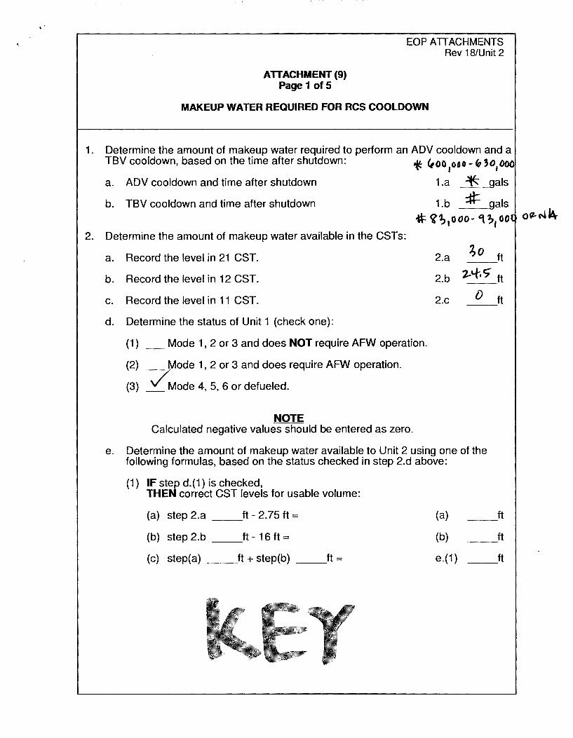
ATTACHMENT(9) Page 1 of 5
EOP ATTACHMENTS Rev 18/Unit 2
MAKEUP WATER REQUIRED FOR RCS COOLDOWN
1. Determine the amount of makeup water required to perform an ADV cooldown and a TBV cooldown, based on the time after shutdown: .u. <,oo ooo - "Jo ooo
°l'- I I
a. ADV cooldown and time after shutdown 1.a -*' gals
b. TBV cooldown and time after shutdown 1.b :tl= gals
if ~; 1000- 't ;1oo
2. Determine the amount of makeup water available in the CSTs:
a. Record the level in 21 CST. 2.a ;o ft
b. Record the level in 12 CST. 2.b 1-"f-, c; ft
C.
d.
Record the level in 11 CST.
Determine the status of Unit 1 (check one):
(1) _ Mode 1, 2 or 3 and does NOT require AFW operation.
(2) _ Mode 1, 2 or 3 and does require AFW operation.
(3) /Mode 4, 5, 6 or defueled.
NOTE Calculated negative values should be entered as zero.
2.c D
e. Determine the amount of makeup water available to Unit 2 using one of the following formulas, based on the status checked in step 2.d above:
(1) IF step d.(1) is checked, THEN correct CST levels for usable volume:
(a) step 2.a ft-2.75ft= (a)
(b) step 2.b ft-16ft= (b)
(c) step(a) ft+ step(b) ft= e.(1)
ft
ft
ft
ft
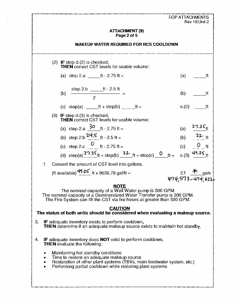
AlTACHMENT (9) Page2 of 5
EOP ATTACHMENTS Rev 18/Unit 2
MAKEUP WATER REQUIRED FOR RCS COOLDOWN
(2) IF step d.(2) is checked, THEN correct CST levels for usable volume:
(a) step 2.a ft - 2.75 ft=
step 2.b ft - 2.5 ft (b) =
2
(c) step(a) ft+ step(b) ft=
(3) IF step d.(3) is checked, THEN correct CST levels for usable volume:
(a) step 2.a 30 ft - 2.75 ft=
(b) step 2.b '2-'-r.S' ft - 2.5 ft =
(c) step 2.c 0 ft - 2.75 ft=
(d) step(a) '2, .i.S'ft + step(b) 1.-1- ft+ step(c)
f. Convert the amount of CST level into gallons.
(ft available) c.t1 ,2.~ ft x 9636. 78 gal/ft =
NOTE
0 ft=
(a)
(b)
e.(2)
(a)
(b)
(c)
__ ft
__ ft
ft --
1.-1.2-~ft
'2/J.- ft
0 ft
e.(3) 4-,.2-s- ft
2.f ~ gals
tf-', If, '?t ~ ..- l.\--1 +i bi l. ~
The nominal capacity of a Well Water pump is 300 GPM. The nominal capacity of a Demineralized Water Transfer pump is 300 GPM.
The Fire System can fill the CST via fire hoses at greater than 500 GPM.
CAUTION The status of both units should be considered when evaluating a makeup source.
3. IF adequate inventory exists to perform cooldown, THEN determine if an adequate makeup source exists to maintain hot standby.
4. IF adequate inventory does NOT exist to perform cooldown, THEN evaluate the following:
• Maintaining hot standby conditions • Time to restore an adequate makeup source • Restoration of other plant systems (TBVs, main feedwater system, etc.) • Performing partial cooldown while restoring plant systems

70000 0
600000
(I) 500000 z 0 _, -;i_ 400000
(!) I
~ 300000
C(
200000
10000
0
...,
j
..
..
0
INVENTORY REQUIRED TO COOL DOWN TO 300°F
I I I - ADV Cooldown • No Fill & Chill .. •• ... TBV Cooldown • 50°F/hour
"' ~ .. " ~ 1:--
'· -··-.,,,.._,, ......
~ -f··-... -... , ............. ~·-···-··· ..... -... -.... 1t,, ........... ·---...... ~ ~
._
. . . . .
10 20 30 40 50 60 70
TIME AFTER SHUTDOWN TO START COOLDOWN - HOURS
1 40000
1 20000
1 00000
0000
60000
.
. 0
80
0000
0000
== ~ m C: ,, ; ~ :a l>
Cl) m ,,~ 0
z C: c! n 0 5j fD :I: _., m wa: _., C 9.~ <( ~ C,
c.n -I ~ -I s
> :a m g ... n
0 0 r-C
i m 0
z "'O )> -i
::D ~ ~ (') -1,. :c ~s:: cm :::, z ;::;: ..., I\) C/)

rn z g ..J <( C,
I
~ z w ~ w a: -::> 0 w a: a: w I-
i ...J
~ ~
MAKEUP WATER REQUIRED TO MAINTAIN HOT STANDBY
600000 i i
500 000 . I
'; i
) . i
400
';.\
300 ~
... ,,,
200 '} -
100000 '/ 0
0
I I
V _ Total • gallons
~ ,_,., Rate- gaVmin I
~ L~ ----
/ ;/ --
V .. ~ ,., ., ... ..... ,, ... ··~ !.!!a ·-.,,. I" ...... -.... ,, ..... ,_. •1i--rn .. .,,_ ........
11 ........ ...... / ...
~ ~
10 20 30 40 50 60 70 80 90
TIME AFTER SHUTDOWN - HOURS
300
.
250
200
.
150
100
50
0 100
i: w ~ I- m ::, C: z 'ti - =e ~ ::::i ~ <( m :c (!J :c >
m ,,~ w 0
ti: C: ~ (') :6 tD :c
a: m A, a: z C om
cS ... z
0 UI~
j:: :c -s Q. :c ~
(') CJ) ::, (') en 0 z 0
0 r-(.) C
0 m a: =e 0 w z "U I- )>
~ :o~ ~ () ..... :c CX) s::: ........ m §=z ;:;: -I I\) C/)
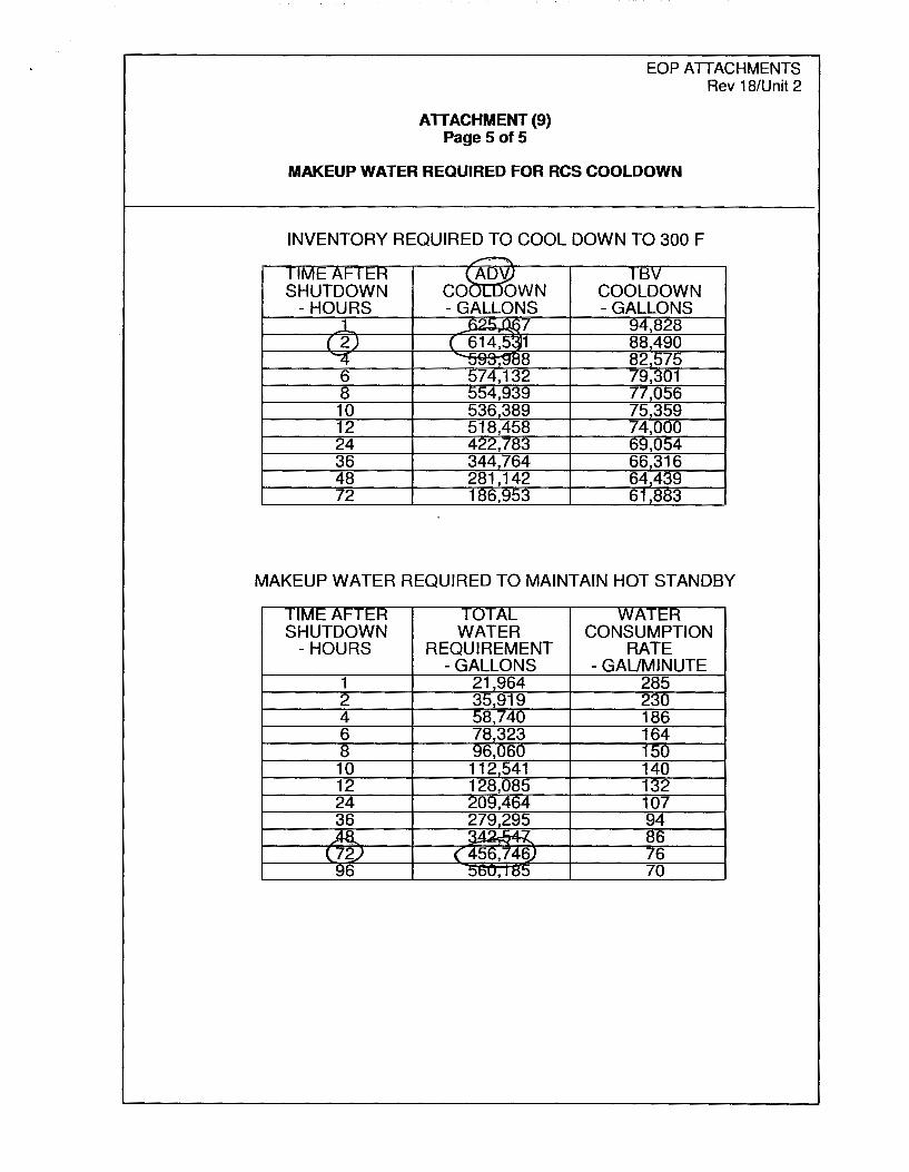
ATTACHMENT (9) Pages of 5
EOP ATTACHMENTS Rev 18/Unit 2
MAKEUP WATER REQUIRED FOR RCS COOLDOWN
INVENTORY REQUIRED TO COOL DOWN TO 300 F ~
TIME AFTER )~
11:SV SHUTDOWN CO OWN COOLDOWN
-HOURS -GALLONS -GALLONS _1 f:,0,:;; n, 7 94,828
( 2) ( 614,5: 1 88,490 4 v.:1S,~c8 82,575 6 574,132 79,301 8 554,939 77,056 10 536,389 75,359 12 518,458 74,000 24 422,783 69,054 36 344,764 66,316 48 281,142 64.439 72 186,953 61,883
MAKEUP WATER REQUIRED TO MAINTAIN HOT STANDBY
SHUTDOWN - HOURS
1 2 4 6 8
10 12 24
WATER REQUIREMENT
-GALLONS 21,964 35,919 58,740 78,323 96,060
112,541 128,085 209,464
CONSUMPTION RATE
-GAUMINUTE 285 230 186 164 150 140 132
0
Appendix C
Initial Conditions:
---~ ----------
Job Performance Measure Worksheet
EXAMINEE'S CUE SHEET
1. You are performing the duties of the Unit-2 CRO.
2. Unit-2 is operating at 100% power when a Station Blackout occurs.
3. EOP-7-2, Station Blackout, is implemented.
Form ES-C-1
4. The need for a Unit-2 plant cooldown is being evaluated with the following current conditions:
• Unit-1 is in Mode 6
• Unit-2 tripped 2 hours ago.
• Unit-2 is in Hot Standby
• The TBVs are not available
• 21 CST level is 30'
• 12 CST level is 24.5'
• 11 CST is empty for maintenance
Initiating Cue:
1. The Unit Supervisor is evaluating the need for a plant cooldown per EOP-7 and assigns you two tasks.
Task 1
Determine if adequate inventory exists to perform a cooldown to 300°F, with current CST levels and no additional makeup, by completing EOP Attachment (9) Steps 1-2. Circle your determination below.
Circle YES, adequate inventory exists to cooldown to 300°F
®dequate inventory does not exist to cooldown to 300°F
Task 2
Determine if adequate inventory exists to maintain Unit-2 in Hot Standby conditions, with current CST levels and no additional makeup, for 72 hours ~-zhe trip, using EOP Attachment (9).Circle your determination below.
~dequate inventory exists to maintain Hot Standby for 72 hours
NO. adequate inventory does not exist to maintain Hot Standby for 72 hours
RO Admin2 Page 13 of 13

Examinee:
Calvert Cliffs Nuclear Power Plant
2018 NRC Initial Licensed Operator Exam
JPM-RO Admin3
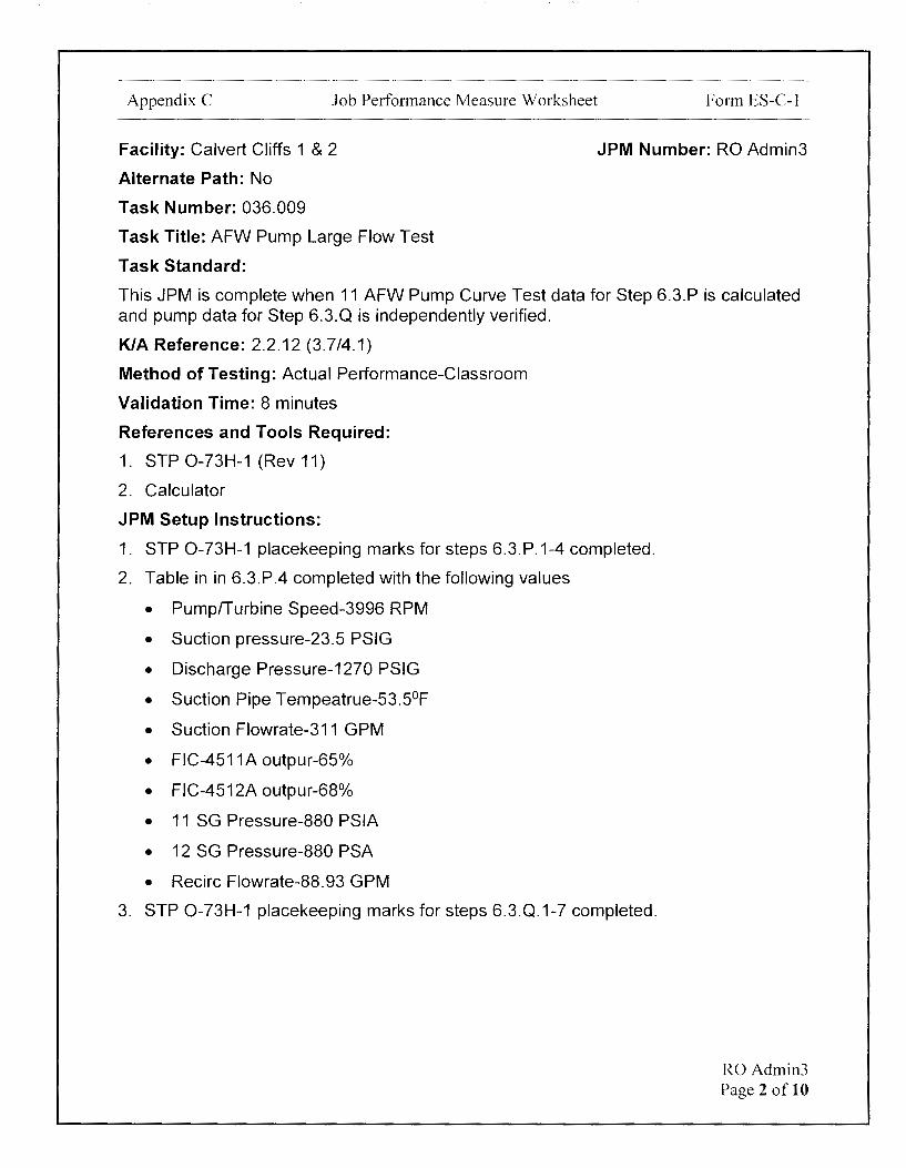
Appendix C Job Performance Measure Worksheet
Facility: Calvert Cliffs 1 & 2
Alternate Path: No
Task Number: 036.009
Task Title: AFW Pump Large Flow Test
Task Standard:
Form ES-C-1
JPM Number: RO Admin3
This JPM is complete when 11 AFW Pump Curve Test data for Step 6.3.P is calculated and pump data for Step 6.3.Q is independently verified.
K/A Reference: 2.2.12 (3.7/4.1)
Method of Testing: Actual Performance-Classroom
Validation Time: 8 minutes
References and Tools Required:
1. STP 0-73H-1 (Rev 11)
2. Calculator
JPM Setup Instructions:
1. STP 0-73H-1 placekeeping marks for steps 6.3.P.1-4 completed.
2. Table in in 6.3.P.4 completed with the following values
• Pump/Turbine Speed-3996 RPM
• Suction pressure-23.5 PSIG
• Discharge Pressure-1270 PSIG
• Suction Pipe Tempeatrue-53.5°F
• Suction Flowrate-311 GPM
• FIC-4511A outpur-65%
• FIC-4512A outpur-68%
• 11 SG Pressure-880 PSIA
• 12 SG Pressure-880 PSA
• Recirc Flowrate-88.93 GPM
3. STP 0-73H-1 placekeeping marks for steps 6.3.Q.1-7 completed.
RO Admin3 Page 2 of 10

Appendix C Job Performance Measure Worksheet Form ES-C-1
4. Table in in 6.3.Q.3 completed with the following values
• Pump/Turbine Speed-3993 RPM
• Suction pressure-26.0 PSIG
• Discharge Pressure-1280 PSIG
• Suction Pipe Tempeatrue-57.8°F
• Suction Flowrate-253 GPM
• FIC-4511A outpur-73%
• FIC-4512A outpur-76%
• 11 SG Pressure-880 PSIA
• 12 SG Pressure-880 PSA
• Recirc Flowrate-89.5 GPM
5. Step 6.3.Q.4 completed with 1280 and 1280.64 PSID as recorded values.
6. Step 6.3.Q.5 completed with 1280.64, 26.0, and 1254.64 PSID as recorded values.
7. Step 6.3.Q.6 completed with 2.309 as recorded value.
8. Step 6.3.Q.47completed with 1254.64, 2.309, and 2896.96 FT as recorded values.
R0Admin3 Page 3 of 10

Appendix C Job Performance Measure Worksheet Form ES-C-1
Directions to the Examinee:
I will explain the initial conditions, which steps to simulate or discuss, and provide initiating cues. When you complete the task successfully, the objective for this job performance measure will be satisfied.
Hand Examinee's Cue Sheet to Examinee at this time.
Initial Conditions:
1. You are performing the duties of the Unit-1 CRO.
2. STP 0-73H-1 is in progress.
3. 11 AFW Pump Curve Test is currently being performed.
Initiating Cue:
1. The Unit Supervisor directs you to first complete Steps 6.3.P.5 through 6.3.P.8.
2. Once Steps 6.3.P.5-8 are completed, the Unit Supervisor directs you to perform an independent verification for 6.3.Q.8. If any errors are identified during the independent verification, circle the errors in the STP.
3. Are there any questions? You may begin.
RO Admin3 Page 4 of 10
Appendix C Job Performance Measure Worksheet Form ES-C-1
1--
STEP STANDARD 1-- <( ELEMENT <( Cl)
Cl) z :::,
TIME START:
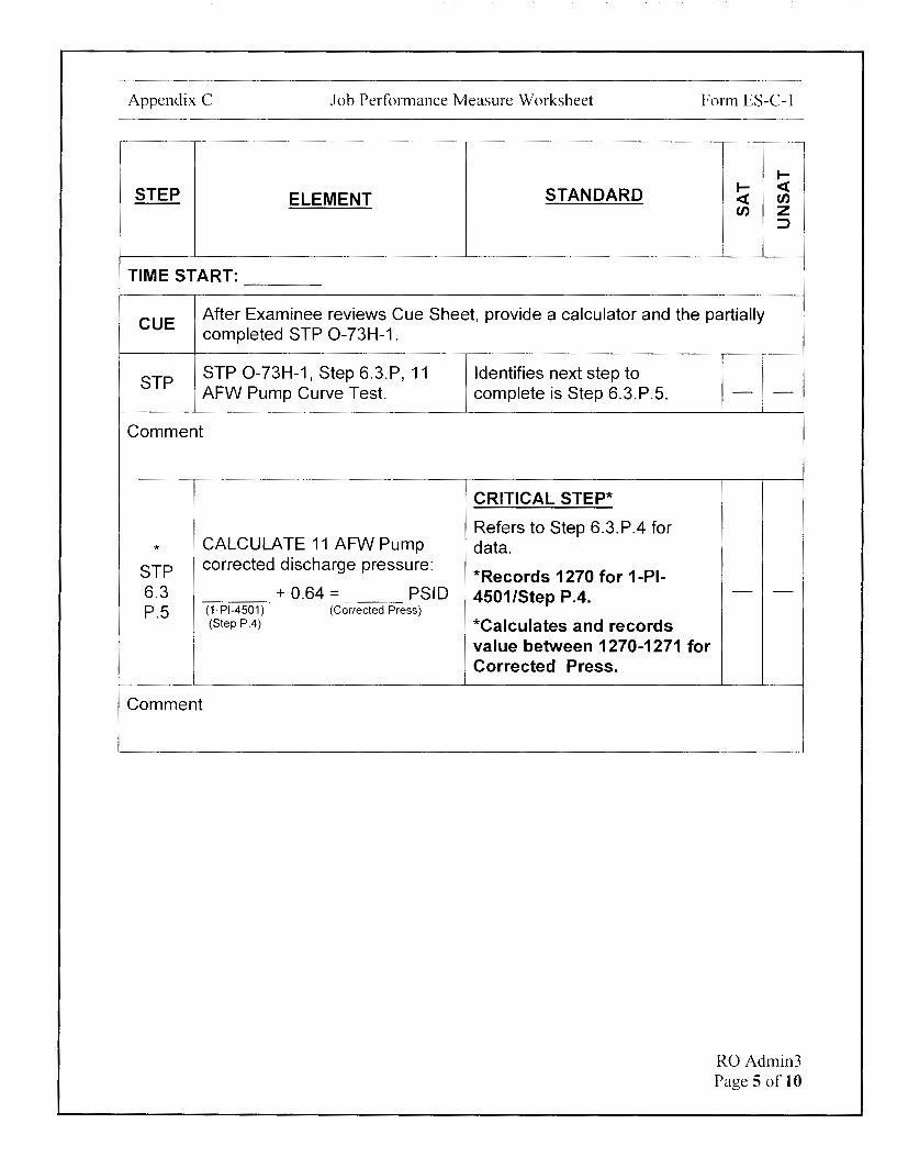
CUE After Examinee reviews Cue Sheet, provide a calculator and the partially completed STP 0-73H-1 .
STP STP 0-73H-1, Step 6.3.P, 11 AFW Pump Curve Test.
Comment
* CALCULATE 11 AFW Pump
STP corrected discharge pressure:
6.3 + 0.64 = PSID P.5 (1-Pl-4501) (Corrected Press)
(Step P.4)
Comment
Identifies next step to complete is Step 6.3.P.5.
CRITICAL STEP*
Refers to Step 6.3.P.4 for data.
*Records 1270 for 1-PI-4501/Step P.4.
*Calculates and records value between 1270-1271 for Corrected Press.
- -
- -
RO Admin3 Page 5 of 10
Appendix C Job Performance Measure Worksheet Form ES-C-1
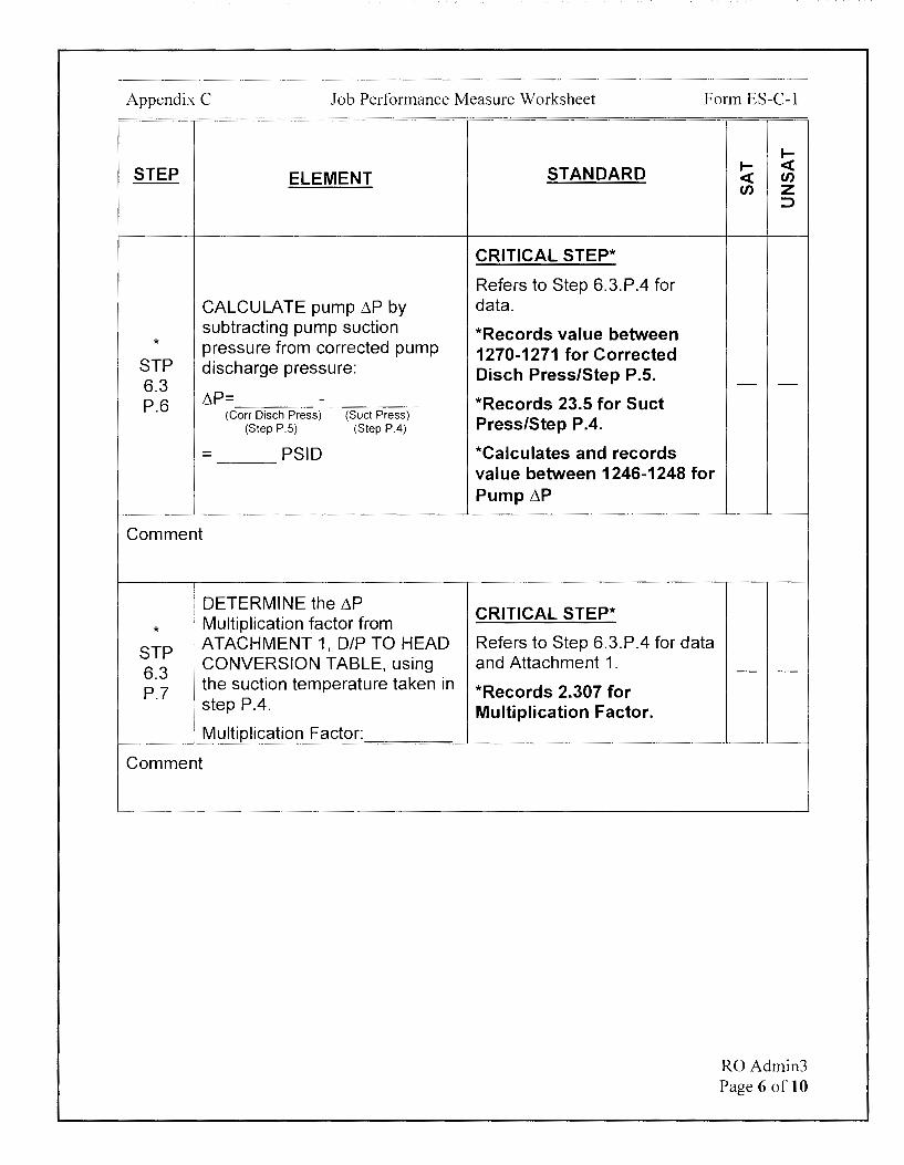
STEP ELEMENT
CALCULATE pump L\P by subtracting pump suction
* pressure from corrected pump STP discharge pressure: 6.3 P.6 L\P= -
(Corr Disch Press) (Suet Press) (Step P.5) (Step P.4)
= PSID
Comment
I ! DETERMINE the L\P
* Multiplication factor from
STP ATACHMENT 1, D/P TO HEAD CONVERSION TABLE, using
6.3 P.7 the suction temperature taken in
step P.4.
Multiplication Factor:
Comment
STANDARD
CRITICAL STEP*
Refers to Step 6.3.P.4 for data.
*Records value between 1270-1271 for Corrected Disch Press/Step P.5.
*Records 23.5 for Suet Press/Step P .4.
*Calculates and records value between 1246-1248 for Pump 11P
CRITICAL STEP*
Refers to Step 6.3.P.4 for data and Attachment 1.
*Records 2.307 for Multiplication Factor.
I-I- <( <( en en z
::>
- -
- -
RO Admin3 Page 6 of 10

Appendix C Job Performance Measure Worksheet Form ES-C-1
STEP ELEMENT
* CALCULATE 11 AFW Pump
STP Total Developed Head Below:
6.3 (~P)X (mull factor)
P.8 (Step P.6) (Step P.7)
= FT (TOH)
Comment
1
STP STP 0-73H-1, Step 6.3.Q, 11 AFW Pump Curve Test.
i
Comment
STANDARD
CRITICAL STEP*
Refers to Step 6.3.P.4 for data.
*Records value between 1246-1248 for Step P.6.
*Records 2.307 for Step P. 7.
*Calculates and records value between 2874-2879 for Total Developed Head.
Identifies next step to complete is Step 6.3.Q.8 based on Examinee Cue Sheet.
1--1-- <( <( en en z
::::,
- -
- -
RO Admin3 Page 7 of 10

Appendix C Job Performance Measure Worksheet Form ES-C-1
.... STEP STANDARD .... <(
ELEMENT <( en en z
:::>
CRITICAL STEP*
Refers to Step 6.3.Q.4 for data and evaluates calculations in steps Q.4, Q.5, Q.6, and Q.7.
Determines Multiplication Factor from Attachment 1 in Step Q.6 is incorrect.
* Independently CHECK *Circles/identifies that STP calculations and Multiplication Multiplication Factor from 6.3 Factor determination in steps Attachment 1 in Step Q.6 is - -Q.8 Q.4, Q.5, Q.6, and Q.7. incorrect.
I Determines Calculation for
I
Total Developed Head in Step Q.7 is incorrect.
*Circles/identifies that calculation for Total Developed Head in Step Q. 7 is incorrect.
Comment
TERMINATING CUE:
This JPM is complete when 11 AFW Pump Curve Test data for Step 6.3.P is calculated and pump data for Step 6.3.Q is independently verified.
The Examinee is expected to end the JPM.
TIME STOP:
RO Admin3 Page 8 of 10
Appendix C Job Performance Measure Worksheet
Verification of Completion
Job Performance Measure Number: RO Admin3
Examinee:
NRC Examiner:
Date Performed:
Facility Evaluator: ________________ _
Number of Attempts: _______________ _
Time to Complete: ________________ _
Follow up Question(s):
Examinee Response:
Result: SATISFACTORY UNSATISFACTORY -- --
Examiner's Signature and Date:
Form ES-C-1
RO Admin3 Page 9 of 10
Appendix C
Initial Conditions:
Job Performance Measure Worksheet
EXAMINEE'S CUE SHEET
1. You are performing the duties of the Unit-1 CRO.
2. STP 0-73H-1 is in progress.
3. 11 AFW Pump Curve Test is currently being performed.
Initiating Cue:
Form ES-C-1
1. The Unit Supervisor directs you to first complete Steps 6.3.P.5 through 6.3.P.8.
2. Once Steps 6.3.P.5-8 are completed, the Unit Supervisor directs you to perform an independent verification for 6.3.Q.8. If any errors are identified during the independent verification, circle the errors in the STP.
RO Admin3 Page 10 of 10

AFW PUMP LARGE FLOW TEST
6.3.P jj AFW PUMP CURVE TEST [82117] (Continued)
5. CALCULATE 11 AFW Pump corrected discharge pressure: \ ~ ,D + 0.64 = ~ PSID ,f:_
STP 0-73H-1 Rev. 11/Unit 1 Page 68 of 125
INITIALS
(l-PI-4501) (Step P.4)
(corrected Press) I d-10- I d-1 (
6. CALCULATE pump 6P by subtracting pump suction pressure from pump corrected discharge pressure:
(d,:10, \~,, ~ ?-?;.S' :\f--L'.P = - = ----- PSID :It- IJ% - ti~
(Corr Disch Press) (Suet Press) (Step P.5) (Step P.4)
7. DETERMINE the 6P multiplication factor from ATTACHMENT 1, D/P TO HEAD CONVERSION TABLE, using the suction temperature taken in step P.4.
Multiplication Factor: i..~o,
\ 8. CALCULATE 11 AFW Pump T1tal Developed Head Below:
~ \2..'-\<-·\2-L\i *- 'J.,'2yo7 ~ ____ (L'.P) X (mul t factor) = FT (Step P.6) (Step P.7)
9. Independently CHECK calculations AND Multiplication Factor determination in steps P.5 through P.8.
(TOH)
v ,-..11, svfBZ-'1 ,s.oe l{t\S G1veJ S""fff 1 111 ~o~ ~o. p~ c~ tllo 17"iSI' l

6.3.Q
AFW PUMP LARGE FLOW TEST
11 AFW PUMP CURVE TEST [82117] (Continued)
0 DETERMINE the t..P multiplication factor from ATTACHMENT 1, D/P TO HEAD CO ION TABLE, using the suction temperature tak in step .
8. Independently CH ulations AND Multiplication Factor determination in steps Q.4, Q.5, 0.6 and 0.7.
R. ESTABLISH a test flow rate of 190-215 GPM as follows:
NOTE
STP 0-73H-1 Rev. 11/Unit 1 Page 71 of 125
INITIALS
Flows should be balanced between controllers to feed equal amounts of AFW to the Steam Generators. j j
1. ADJUST BOTH 11 S/G Flow Controller 1-FIC-4511A AND 12 SIG Flow Controller 1-FIC-4512A to obtain an average suction flowrate of 190-215 GPM for 5 minutes at 3980 to 4000 RPM. ( 5 minute average read on Ultrasonic Flowmeter.)
2. CHECK S/G levels are being properly maintained between ±10 inches.
Examinee:
Calvert Cliffs Nuclear Power Plant
2018 NRC Initial Licensed Operator Exam
JPM-RO Admin4

Appendix C Job Performance Measure Worksheet Form ES-C-1
Facility: Calvert Cliffs 1 & 2
Alternate Path: No
Task Number: 204.111
Task Title: Perform duties as Emergency Communicator
Task Standard:
JPM Number: RO Admin4
This JPM is complete when the ERO is activated using the primary method via the Training Everbridge account. (Time Critical)
K/A Reference: 2.4.39 (3.9/3.8)
Method of Testing: Actual Performance-Classroom
Validation Time: 7 minutes
References and Tools Required:
1. Shift Communicator Binder
2. EP-AA-112-100-F-57 (ERONS Notification Details)
JPM Setup Instructions:
1. Shift Communicator binder is available.
2. Place keep the Shift Communicator Checklist (EP-AA-112-100-F-51) to indicate that Initial Actions 1.1 is completed and Initial Actions 1.2 and 1.3 are in progress.
3. Create a completed Training Version of EP-AA-112-1 OO-F-57 (ERONS Notification Details) with the following information completed:
• 1.1 "Calvert Cliffs" is circled • 1.2 "Simulator Actual Event Respond to Facility" is circled • Write time of 1315 at bottom of first page.
4. An internet assessable computer with Everbridge shortcut is available.
RO Admin4 Page 2 of 12
Appendix C Job Performance Measure Worksheet Form ES-C-1
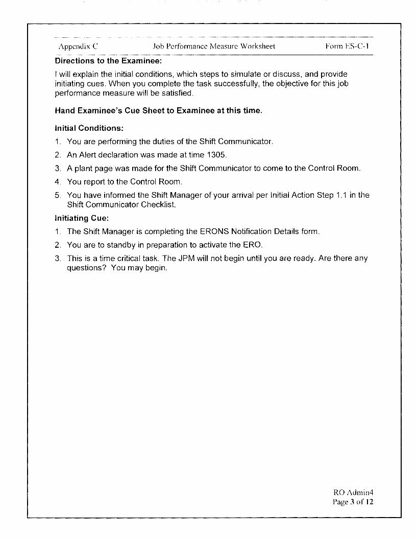
Directions to the Examinee:
I will explain the initial conditions, which steps to simulate or discuss, and provide initiating cues. When you complete the task successfully, the objective for this job performance measure will be satisfied.
Hand Examinee's Cue Sheet to Examinee at this time.
Initial Conditions:
1. You are performing the duties of the Shift Communicator.
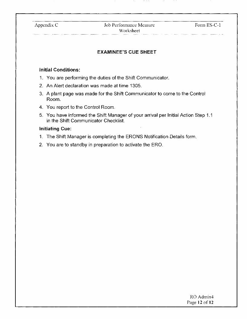
2. An Alert declaration was made at time 1305.
3. A plant page was made for the Shift Communicator to come to the Control Room.
4. You report to the Control Room.
5. You have informed the Shift Manager of your arrival per Initial Action Step 1.1 in the Shift Communicator Checklist.
Initiating Cue:
1. The Shift Manager is completing the ERONS Notification Details form.
2. You are to standby in preparation to activate the ERO.
3. This is a time critical task. The JPM will not begin until you are ready. Are there any questions? You may begin.
RO Adrnin4 Page 3 of 12

Appendix C Job Performance Measure Worksheet Form ES-C-1
I-
STEP STANDARD I- <( ELEMENT <( en
en z :::>
TIME START:
Examiner NOTE
The intent of this JPM is to activate the Training Everbridge account. The Examinee will not actually activate the ERO when performing this task. It is important to verify that the Training ERONS Notification Details Form is used as this form contains passwords that ensure only the Training Everbridge account is accessed during this JPM.
The time critical part of the JPM starts when the ERONS Notification Details Form is handed to the Operator.
CUE After Examinee reviews Cue Sheet, provide the operator with the Shift Communicator binder.
!
Identifies next step to
, Locates Shift Communicator complete in Shift
sec 1
1 binder. Communicator Checklist is - -EP-AA-112-100-F-51 Steps
I
1.2 and 1.3.
Comment
Provide a copy of the Training ERONS Notification Details Form, EP-AA-112-110-F-57.
CUE Activate the ERO per the ERONS Notification Details Form.
Note ERONS Start Time
If directed by the Shift Manager, Determines step is applicable based on Cue.
sec then INITIATE ERO Activation 1.3 (call out) using an ERO Proceeds to EP-AA-112-110-
Notification form. F-57, ERONS Notification Details (CNG).
Comment
- -
RO Admin4 Page 4 of 12
Appendix C Job Performance Measure Worksheet Form ES-C-1
I-
STEP STANDARD I- <( ELEMENT <( en
en z ::,
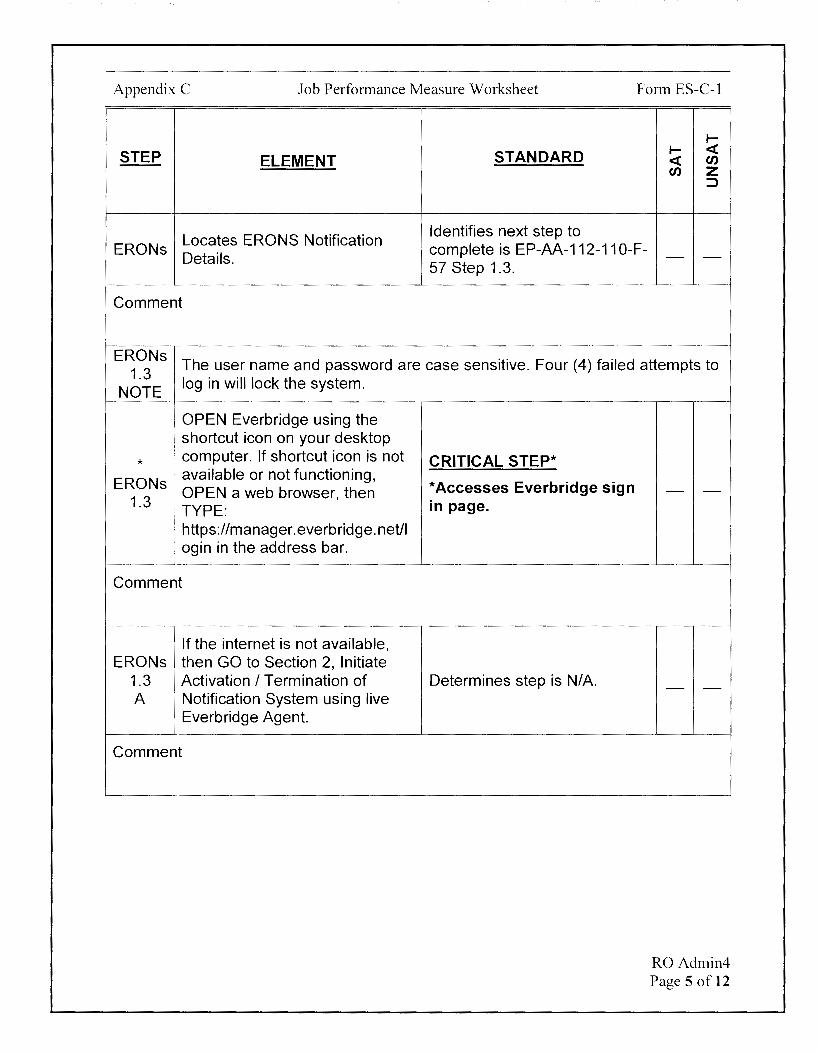
Locates ERONS Notification Identifies next step to
ERONs complete is EP-AA-112-110-F-Details. - -
57 Step 1.3.
Comment
ERONs The user name and password are case sensitive. Four (4) failed attempts to
1.3 NOTE
log in will lock the system.
[ OPEN Everbridge using the • shortcut icon on your desktop
* computer. If shortcut icon is not
ERONs available or not functioning, OPEN a web browser, then
1.3 . TYPE: : https://manager.everbridge.net/1 ogin in the address bar.
Comment
If the internet is not available, ERONs then GO to Section 2, Initiate
1.3 Activation I Termination of A Notification System using live
Everbridge Agent.
Comment
CRITICAL STEP*
*Accesses Everbridge sign in page .
Determines step is N/A.
- -
- -
RO Admin4 Page 5 of 12
Appendix C Job Performance Measure Worksheet Form ES-C-1
1--
STEP STANDARD 1-- <C ELEMENT <C en
en z ::>
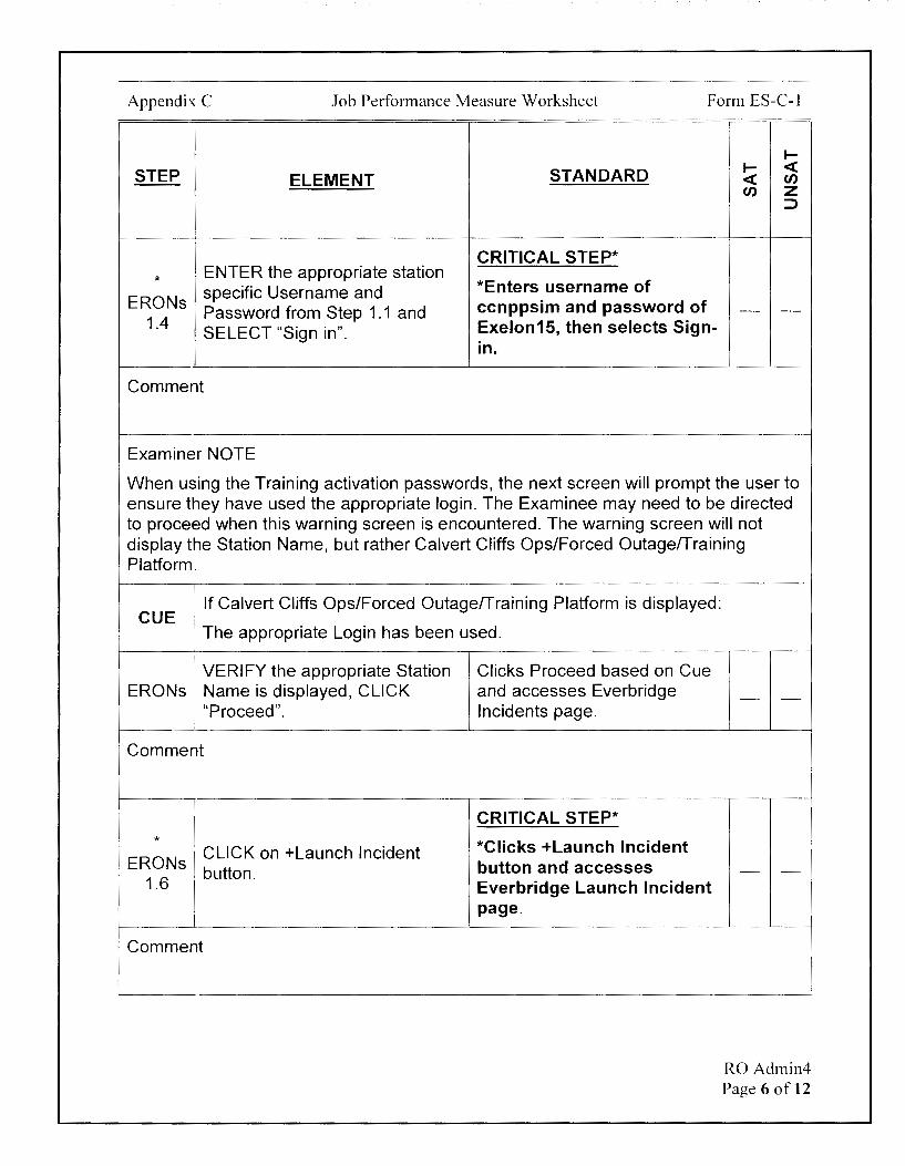
CRITICAL STEP* *
ENTER the appropriate station *Enters username of specific Username and
ERONs Password from Step 1.1 and ccnppsim and password of - -
1.4 SELECT "Sign in". Exelon15, then selects Sign-
in.
Comment
Examiner NOTE
When using the Training activation passwords, the next screen will prompt the user to ensure they have used the appropriate login. The Examinee may need to be directed to proceed when this warning screen is encountered. The warning screen will not display the Station Name, but rather Calvert Cliffs Ops/Forced Outage/Training Platform.
CUE / 1t Calvert Cliffs Ops/Forced Outage!Training Platform is displayed:
I The appropriate Login has been used. I
VERIFY the appropriate Station Clicks Proceed based on Cue ERONs Name is displayed, CLICK and accesses Everbridge
"Proceed". Incidents page.
Comment
CRITICAL STEP* * *Clicks +Launch Incident CLICK on +Launch Incident
ERONs button. button and accesses
1.6 Everbridge Launch Incident page.
Comment
- -
- -
RO Admin4 Page 6 of 12
Appendix C Job Performance Measure Worksheet Form ES-C-1
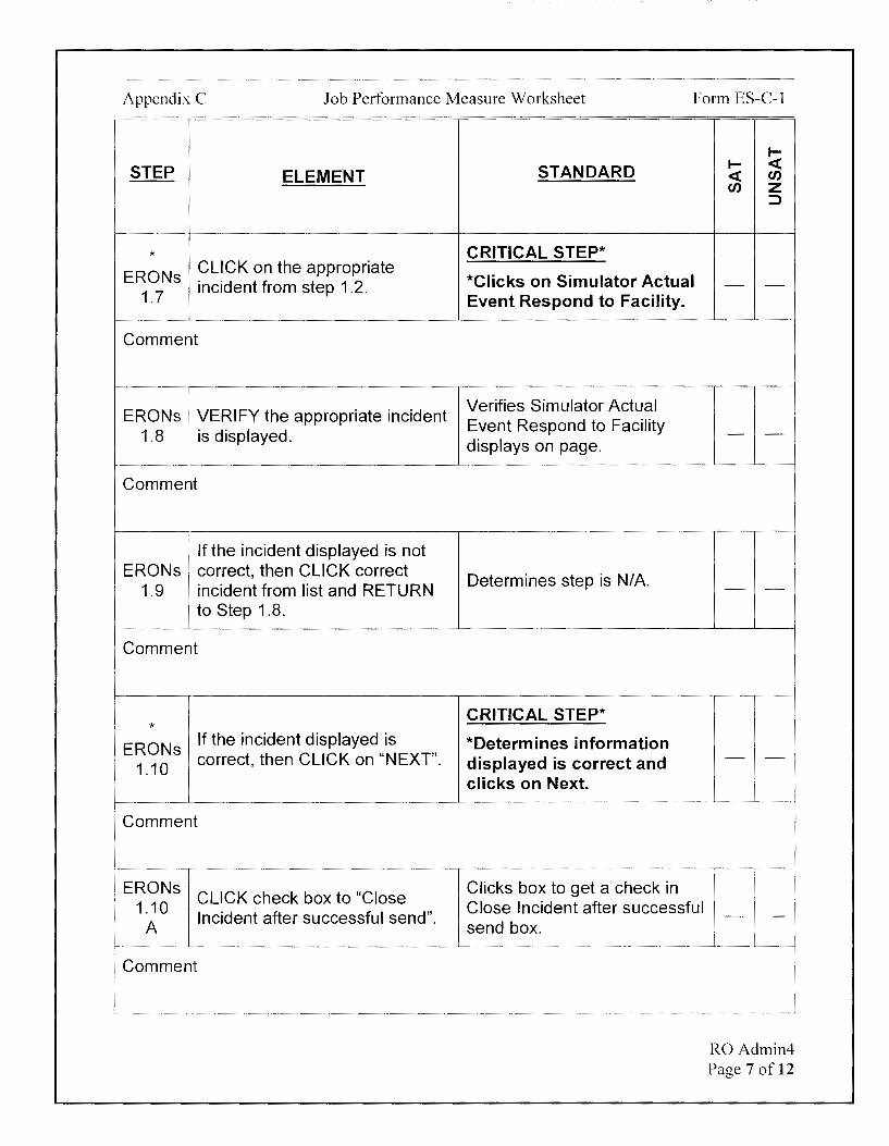
STEP ELEMENT
* ERONs
CLICK on the appropriate incident from step 1.2.
1.7
Comment
ERONs VERIFY the appropriate incident 1.8 : is displayed.
Comment
I I
' If the incident displayed is not ERONs correct, then CLICK correct
1.9 incident from list and RETURN to Step 1.8.
Comment
* ERONs
If the incident displayed is correct, then CLICK on "NEXT".
1.10
Comment
ERONs CLICK check box to "Close
1.10 Incident after successful send".
A
Comment
STANDARD
CRITICAL STEP*
*Clicks on Simulator Actual Event Respond to Facility.
Verifies Simulator Actual Event Respond to Facility displays on page.
Determines step is N/A.
CRITICAL STEP*
*Determines information displayed is correct and clicks on Next.
Clicks box to get a check in Close Incident after successful send box.
I-I- ~ ~ en en z
::J
- -
- -
- -
- -
- -
RO Admin4 Page 7 of 12
Appendix C Job Performance Measure Worksheet Form ES-C-1
I-
STEP STANDARD I- <( ELEMENT <( en
en z :::,
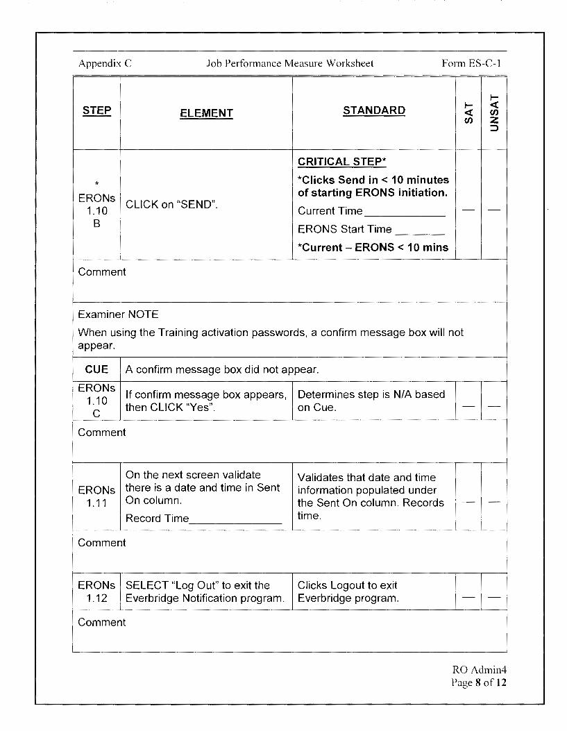
CRITICAL STEP*
* *Clicks Send in < 10 minutes
ERONs of starting ERONS initiation.
1.10 CLICK on "SEND".
Current Time - -B ERONS Start Time
I *Current - ERONS < 10 mins
Comment
Examiner NOTE
When using the Training activation passwords, a confirm message box will not appear.
CUE A confirm message box did not appear.
ERONs If confirm message box appears, Determines step is N/A based
1.10 then CLICK "Yes". on Cue.
C
Comment
On the next screen validate Validates that date and time ERONs there is a date and time in Sent information populated under
1.11 On column. the Sent On column. Records
Record Time time.
Comment
ERONs SELECT "Log Out" to exit the Clicks Logout to exit 1.12 Everbridge Notification program. Everbridge program.
Comment
- -
- -
- -
RO Admin4 Page 8 of 12

Appendix C Job Performance Measure Worksheet Form ES-C-1
I-
STEP STANDARD I- ,ct ELEMENT ,ct rn
rn z =>
Examiner NOTE
When using the Training Everbridge account, the remaining activities associated with activating the ERO will not occur and must be simulated. The Examiner should ask what actions are required when the ERO is activated and what actions would be taken if the ERO was not activated.
Ask the Examinee: CUE What are the expected responses and any further actions required once
logging out of Everbridge?
ERONs 1.13 Additional actions required. 1.15
Comment
Determines that a call to the Control Room from the ERO notification system should be received within 10 minutes after initiating the system.
Determines the Shift Emergency Director/Shift Manager should be notified of ERONS initiation.
- -
RO Admin4 Page 9 of 12

Appendix C Job Performance Measure Worksheet Form ES-C-1
1--
STEP STANDARD 1-- <C ELEMENT <C en
en z :>
Ask the Examinee: CUE What actions would be required if a call was not received in the Control
Room from the ERO notification system?
Actions if a confirmation call was Alternate activation method of
ERONs not received in the Control
calling an Everbridge Live 1.14
! Room. Agent via the telephone would - -need to be initiated.
Comment
TERMINATING CUE:
This JPM is complete when the ERO is activated using the primary method via the Training Everbridge account.
The Examiner is expected to end the JPM.
TIME STOP:
RO Admin4 Page 10 of 12

Appendix C Job Performance Measure Worksheet
Verification of Completion
Job Performance Measure Number: RO Admin4
Examinee:
NRC Examiner:
Date Performed:
Facility Evaluator: ________________ _
Number of Attempts: ________________ _
Time to Complete: ________________ _
Follow up Question(s):
Examinee Response:
Result: SATISFACTORY UNSATISFACTORY -- --
Examiner's Signature and Date:
Form ES-C-1
RO Admin4 Page 11 of 12
Appendix C
Initial Conditions:
Job Performance Measure Worksheet
EXAMINEE'S CUE SHEET
1. You are performing the duties of the Shift Communicator.
2. An Alert declaration was made at time 1305.
Form ES-C-1
3. A plant page was made for the Shift Communicator to come to the Control Room.
4. You report to the Control Room.
5. You have informed the Shift Manager of your arrival per Initial Action Step 1.1 in the Shift Communicator Checklist.
Initiating Cue:
1. The Shift Manager is completing the ERONS Notification Details form.
2. You are to standby in preparation to activate the ERO.
RO Admin4 Page 12 of 12
Examinee: -----
Calvert Cliffs Nuclear Power Plant
2018 NRC Initial Licensed Operator Exam
JPM-SRO Admin1

Appendix C Job Performance Measure Worksheet Form ES-C-1
Facility: Calvert Cliffs 1 & 2
Alternate Path: No
JPM Number: SRO Admin1
Task Number: 203.013
Task Title: Verify Core Alteration preparations are complete
Task Standard:
This JPM is complete when the OP-7 Core Alteration Checklist has been reviewed and steps signed off for conditions met and entries made on the Core Alteration Checklist Issue Tracking for conditions not currently met.
KIA Reference: 2.1.36 (3.0/4.1)
Method of Testing: Actual Performance-Classroom
Validation Time: 18 minutes
References and Tools Required:
1. OP-7 Core Alteration Checklist for Fuel Movement
2. OP-CA-114, Containment Closure
3. Refueling Tech Specs (3.9)
4. Refueling Machine TRM (15.9.3)
5. 01-220, Fuel Handling Area Ventilation System
6. NEOP-13 Figure 1.11.A.6.
7. COLR for Tech Spec 3.9.1
8. eSOMS logs search for Core Alteration related entries (STP 0-59, STP 0-60, STP 0-55A, Containment Closure Tags, etc.)
9. Two pages of Core Alteration Checklist Issue Tracking Sheet.
SRO Adminl Page 2 of 17

Appendix C Job Performance Measure Worksheet Form ES-C-1
JPM Setup Instructions:
1. OP-7-1 placekeeping marks for Steps 6.9.B.2 d, f, g h, i, j, k (except for Operations), I, m, n, and o completed.
2. OP-7-1 placekeeping marks for Steps, 6.9.8.3.a, d, e, and f completed.
3. OP-7-1 placekeeping marks for Steps 6.9.8.4.c, d, f, and g completed.
4. eSOMS log search completed per the attached.
5. Two page Core Alteration Checklist Issue Tracking Sheet created per the attached.
6. Row 1 completed on Core Alteration Checklist Issue Tracking Sheet with Step 2.k and Operations Surveillance Requirements.
7. Picture of 1C10 with 11 IRU available and 12/13 IRU OOS.
8. Picture of 1 C34 with SFP ventilation fans all secured and Charcoal Filters bypassed.
9. Picture ofTR-351 with RCS temperatures of 110°F.
SRO Adminl Page 3 of 17
Appendix C Job Performance Measure Worksheet Form ES-C-1
Directions to the Examinee:
I will explain the initial conditions, which steps to simulate or discuss, and provide initiating cues. When you complete the task successfully, the objective for this job performance measure will be satisfied.
Hand Examinee's Cue Sheet to Examinee at this time.
Initial Conditions:
1. You are performing the duties of an extra SRO.
2. Unit-1 is in Mode 6 preparing to perform a full core off-load.
3. This will be the first movement of fuel this outage on Unit-1.
4. 11 LPSI Pump is in service with Shutdown Cooling Flow at 3000 GPM.
5. Required Refueling Boron Concentration per NEOP-13 and COLR is.:::. 2560 PPM.
6. Today's date is 8/5/18 and time is 1200
7. Fuel offload is scheduled to begin at 1800 today.
8. OP-7 Step 6.9.B, Core Alternation Checklist for Fuel Movement, has been partially completed.
Initiating Cue:
1. The Shift Manager has directed you to complete the Core Alternation Checklist for Fuel Movement, per OP-7 Step 6.9.B.
2. An administrative aid, a Core Alteration Checklist Issue Tracking Sheet, has been created to communicate issues with the Outage Control Center.
3. Document any issues/deviations (i.e. steps that currently cannot be signed off) that prevent moving fuel on the Core Alteration Checklist Issue Tracking Sheet.
4. Are there any questions? You may begin.
SRO Adminl Page 4 of 17
Appendix C Job Performance Measure Worksheet Form ES-C-1
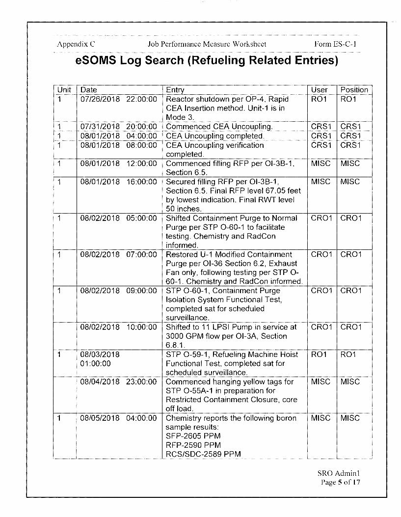
eSOMS Log Search (Refueling Related Entries)
Unit Date 1 07/26/2018 22:00:00
1 07/31/2018 20:00:00 1 08/01/2018 04:00:00 1 08/01/2018 08:00:00
1 08/01/2018 12:00:00
1 08/01/2018 16:00:00
1 08/02/2018 05:00:00
1 08/02/2018 07:00:00
1 08/02/2018 09:00:00
08/02/2018 10:00:00
1 08/03/2018 01:00:00
08/04/2018 23:00:00
1 08/05/2018 04:00:00
Entry Reactor shutdown per OP-4, Rapid CEA Insertion method. Unit-1 is in Mode 3. Commenced CEA Uncoupling. CEA Uncoupling completed. CEA Uncoupling verification completed. Commenced filling RFP per 01-38-1, Section 6.5. Secured filling RFP per 01-38-1, Section 6.5. Final RFP level 67.05 feet by lowest indication. Final RWT level 50 inches. Shifted Containment Purge to Normal Purge per STP 0-60-1 to facilitate testing. Chemistry and RadCon informed. Restored U-1 Modified Containment Purge per 01-36 Section 6.2, Exhaust Fan only, following testing per STP 0-60-1. Chemistry and RadCon informed. STP 0-60-1, Containment Purge Isolation System Functional Test, completed sat for scheduled surveillance. Shifted to 11 LPSI Pump in service at 3000 GPM flow per Ol-3A, Section 6.8.1. STP 0-59-1, Refueling Machine Hoist Functional Test, completed sat for scheduled surveillance. Commenced hanging yellow tags for STP 0-55A-1 in preparation for Restricted Containment Closure, core off load. Chemistry reports the following boron sample results: SFP-2605 PPM RFP-2590 PPM RCS/SDC-2589 PPM
User Position R01 R01
CRS1 CRS1 CRS1 CRS1 CRS1 CRS1
MISC MISC
MISC MISC
CR01 CR01
CR01 CR01
CR01 CR01
CR01 CR01
R01 R01
MISC MISC
MISC MISC
SRO Adminl Page 5 of 17
Appendix C Job Performance Measure Worksheet Form ES-C-1
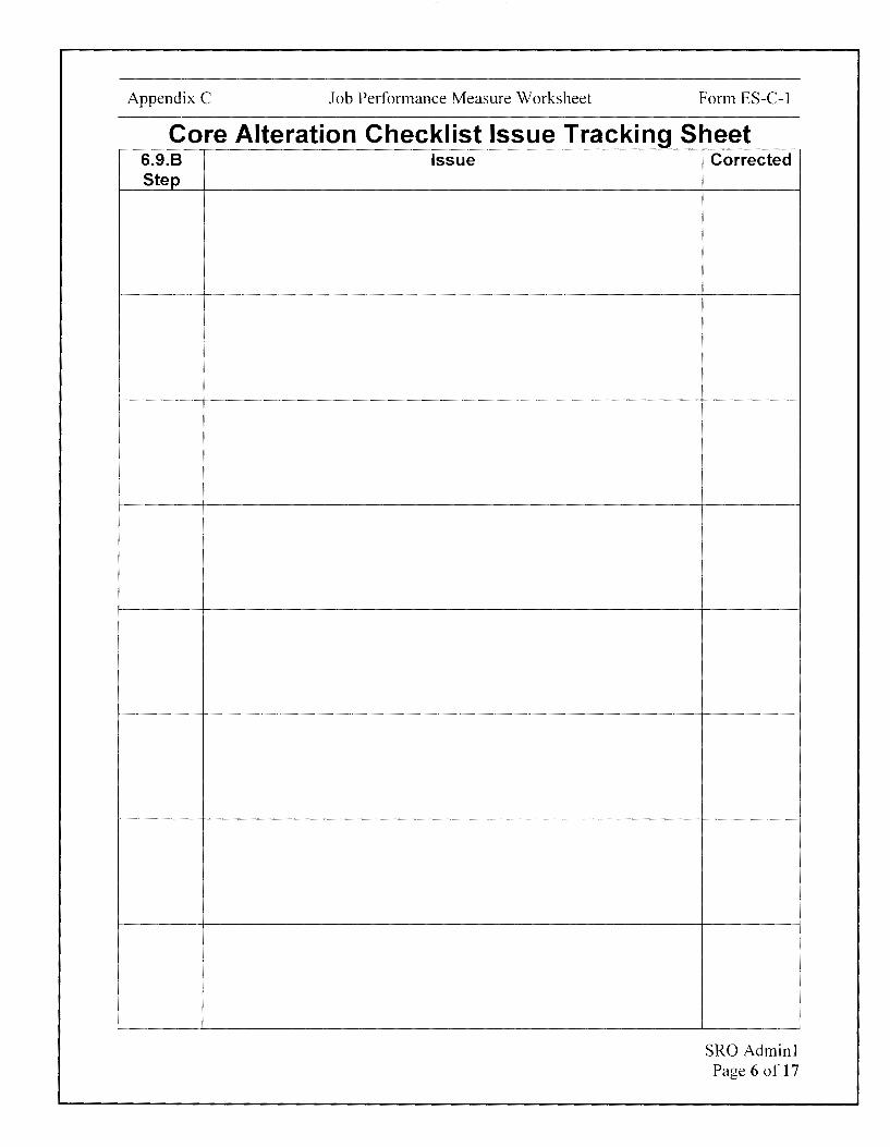
Core Alteration Checklist Issue Tracking Sheet 6.9.8 Issue Step
Corrected
SRO Adminl Page 6 of 17

Appendix C Job Performance Measure Worksheet Form ES-C-1
..... STEP ELEMENT STANDARD ..... <C
<C en en z :::::>
TIME START: ----
Examiner NOTE
Multiple steps in the OP-7 Core Alteration Checklist are marked as complete when the Examinee starts the JPM. Only steps needing evaluation by the Examinee are included in the JPM.
After Examinee reviews Cue Sheet, provide:
• Partially completed OP-7, Core Alteration Checklist for Fuel Movement • OP-CA-114, Containment Closure • Refueling Tech Specs (3.9) • Refueling Machine TRM (15.9.3)
CUE • 01-220, Fuel Handling Area Ventilation System • NEOP-13 Figure 1.11.A.6 and COLR for Tech Spec3.9.1 • eSOMS logs search for Core Alteration related entries (STP 0-59, STP
0-60, STP 0-55A, Containment Closure Tags, etc.) • Partially completed Core Alteration Checklist Issue Tracking Sheet. • Picture of TR-351 with RCS temperatures • Picture of IRUs on 1C10 • Picture of SFP Ventilation on 1 C34
I OP-7, Core Alteration Checklist
OP-7 1 for Fuel Movement.
Comment
6.9.B 1
IF onloading an empty core, THEN verify the Core Support Plate cleanliness is acceptable for fuel onload. (N/A if NOT onloading an empty core.)
Comment
Identifies next step to complete is Step 6.9.8.1.
Determines Step is NIA based on Cue Sheet.
Marks step NIA.
SRO Adminl Page 7 of 17
Appendix C Job Performance Measure Worksheet Form ES-C-1
t-
STEP STANDARD t- <( ELEMENT <( en
en z :::,
6.9.B 2 Steps in this section may be performed concurrently and in any order.
NOTE
IF performing core alterations 6.9.B MORE THAN 72 HOURS since
2 the last core alteration, THEN PERFORM THE following:
Comment
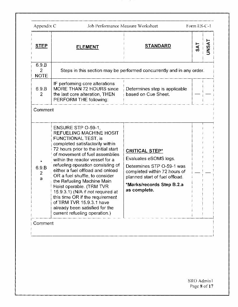
ENSURE STP 0-59-1, REFUELING MACHINE HOSIT FUNCTIONAL TEST, is completed satisfactorily within 72 hours prior to the initial start of movement of fuel assemblies
* within the reactor vessel for a
6.9.B ! refueling operation consisting of
2 either a fuel offload and onload
I OR a fuel shuffle, to consider a
the Refueling Machine Main Hoist operable. (TRM TVR 15.9.3.1) (NIA if not required at this time OR if the requirement ofTRM TVR 15.9.3.1 have already been satisfied for the current refueling operation.)
Comment
Determines step is applicable based on Cue Sheet.
CRITICAL STEP*
Evaluates eSOMS logs.
Determines STP 0-59-1 was completed within 72 hours of planned start of fuel offload.
*Marks/records Step 8.2.a as complete.
- -
- -
SRO Adminl Page 8 of 17
Appendix C Job Performance Measure Worksheet Form ES-C-1
STEP ELEMENT
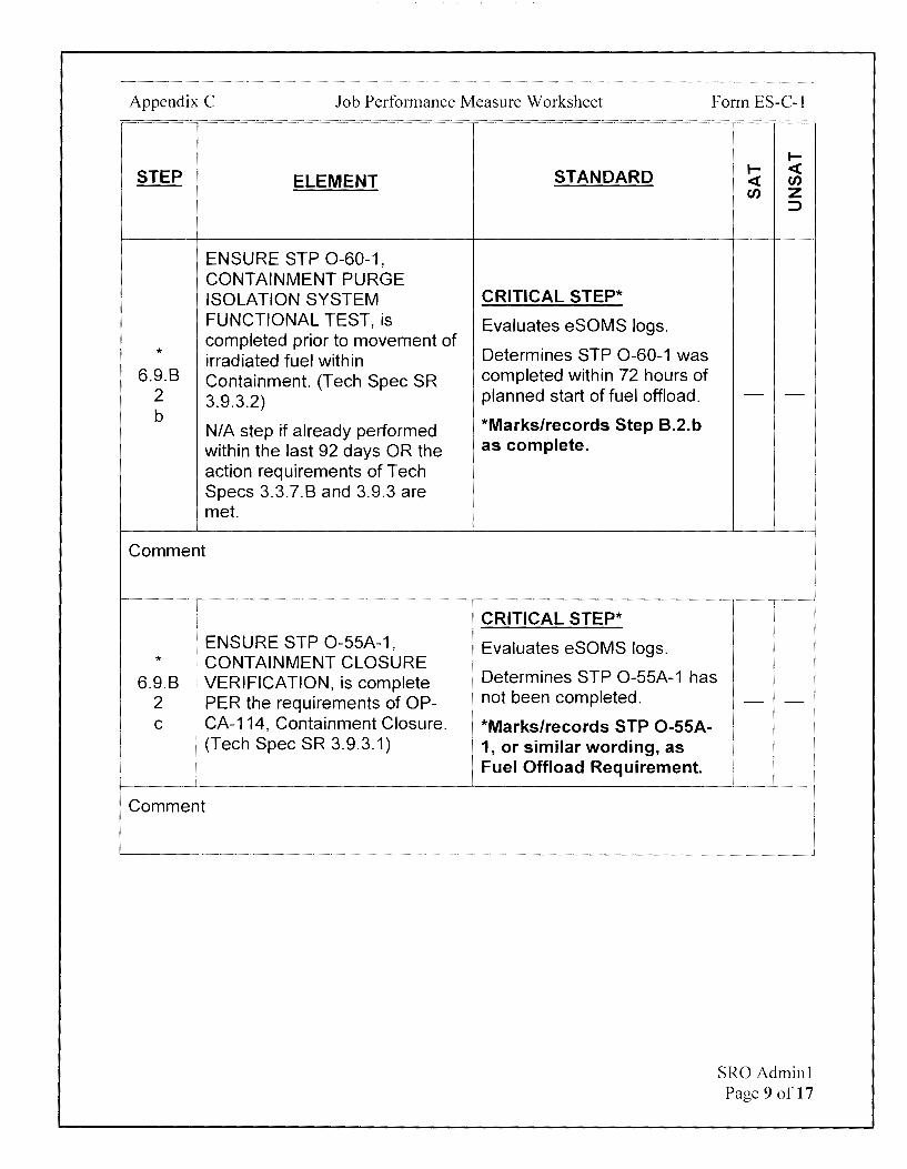
ENSURE STP 0-60-1, CONTAINMENT PURGE ISOLATION SYSTEM FUNCTIONAL TEST, is
* completed prior to movement of irradiated fuel within
6.9.B Containment. (Tech Spec SR 2 3.9.3.2) b
NIA step if already performed within the last 92 days OR the action requirements of Tech Specs 3.3.7.B and 3.9.3 are met.
Comment
ENSURE STP 0-55A-1, * CONTAINMENT CLOSURE
6.9.B VERIFICATION, is complete 2 PER the requirements of OP-C ! CA-114, Containment Closure.
' (Tech Spec SR 3.9.3.1)
Comment
STANDARD
CRITICAL STEP*
Evaluates eSOMS logs.
Determines STP 0-60-1 was completed within 72 hours of planned start of fuel offload.
*Marks/records Step 8.2.b as complete.
CRITICAL STEP*
Evaluates eSOMS logs.
Determines STP 0-55A-1 has not been completed.
*Marks/records STP 0-55A-1, or similar wording, as Fuel Offload Requirement.
I-I- <( <( en en z
::>
- -
- -
SRO Adminl Page 9 of 17

Appendix C Job Performance Measure Worksheet Form ES-C-1
STEP ELEMENT
ENSURE the Containment
* Closure tags are controlled by
6.9.B STP 0-55A-1 and OP-CA-114,
2 CONTAINMENT CLOSURE during movement of irradiated
e fuel assemblies within containment.
Comment
REQUEST the responsible
6.9.B 1
discipline VERIFY Surveillance : Requirements under their
2 I responsibility are current to k , allow core alterations AND are
' established on the schedule to remain current:
Comment
I-
STANDARD I- <C <C en en z
:::>
CRITICAL STEP*
Evaluates eSOMS logs.
Determines Containment Closure tags have not been all hung per STP 0-55A-1 and OP-CA-114. - -
*Marks/records Containment Closure tags, or similar wording, as Fuel Offload Requirement.
Determines Operations has not verified Surveillance requirements are current yet.
Marks/records Operations Surveillance Requirements, or similar wording, as Fuel Offload Requirement
OR
Determines condition is already listed on Fuel Offload Requirement.
- -
SRO Adminl Page 10 of 17

Appendix C Job Performance Measure Worksheet Form ES-C-1
1--
STEP STANDARD 1-- <( ELEMENT <( en
en z ::>
ENSURE the Reactor has been CRITICAL STEP*
* subcritical for at least 100 hours Evaluates eSOMS logs.
6.9.B (TRM TVR 15.9.1.1) prior to
Determines Reactor has been movement of irradiated fuel 3 subcritical for > 100 hours. - -b
assemblies in the reactor vessel. (N/A if couple CEAs after fuel *Marks/records Step 8.3.b movement) as complete.
Comment
CRITICAL STEP*
Evaluates eSOMS logs. * The RCS (SOC), RFP, and SFP Determines RCS (SOC), RFP,
6.9.B boron concentrations are greater and SFP are all greater than 3 than the Refueling Boron NEOP-13/COLR value of> - -C Concentration PER NEOP-13. 2560 PPM.
' *Marks/records Step 8.3.c
\ as complete.
Comment
6.9.B 4 Steps in this section may be performed concurrently and in any order.
NOTE
IF performing core alterations 6.9.B MORE THAN ONE HOUR since
4 the last core alteration, THEN PERFORM the following:
Comment
Determines step is applicable based on Cue Sheet. - -
SRO Adminl Page 11 of 17
Appendix C Job Performance Measure Worksheet Form ES-C-1
STEP ELEMENT
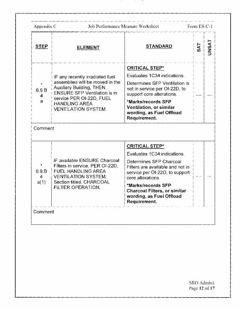
IF any recently irradiated fuel
* assemblies will be moved in the
6.9.B Auxiliary Building, THEN
4 ENSURE SFP Ventilation is in
a service PER Ol-22D, FUEL HANDLING AREA VENTILATION SYSTEM.
Comment
I I I
: IF available ENSURE Charcoal * Filters in service, PER Ol-22D,
6.9.B I FUEL HANDLING AREA 4 . VENTILATION SYSTEM,
a(1) Section titled, CHARCOAL FILTER OPERATION.
Comment
.... STANDARD
.... <( <( en en z
::>
CRITICAL STEP*
Evaluates 1 C34 indications.
Determines SFP Ventilation is not in service per Ol-22D, to support core alterations. - -
*Marks/records SFP Ventilation, or similar wording, as Fuel Offload Requirement.
CRITICAL STEP*
Evaluates 1 C34 indications.
Determines SFP Charcoal Filters are available and not in service per Ol-22D, to support core alterations.
*Marks/records SFP Charcoal Filters, or similar wording, as Fuel Offload Requirement.
- -
SRO Adminl Page 12 of 17
Appendix C Job Performance Measure Worksheet Form ES-C-1
STEP ELEMENT
ESTABLISH direct
6.9.B communications between the
4 Control Room and personnel at
b the refueling station(s), within 1 hour prior to the start of core alterations (TRM 15.9.2)
Comment
* 6.9.B
ENSURE at least one
4 1 Containment Iodine Filter is
' available for service. e
Comment
STANDARD
Determines current time is > 1 hour before start of core alterations.
Marks/records Direct Communications, or similar wording, as Fuel Offload Requirement.
OR
Leaves step unmarked since not applicable until within 1 hour prior to start of core alterations.
CRITICAL STEP*
Evaluates 1C10 indications.
Determines 11 IRU is available.
*Marks/records Step 8.4.e as complete.
I-I- <( <( en en z
:::,
- -
- -
SRO Adminl Page 13 of 17

Appendix C Job Performance Measure Worksheet Form ES-C-1
STEP ELEMENT
* The RCS temperature is greater
6.9.B 4
than 70°F and less than or equal
h to 140°F (SR 3.9.1.1)
Comment
\ 1f moving fuel assemblies within
* / containment, THEN SOC loop in
6.9.B operation circulating reactor coolant at a flow rate of >1500
4 , gpm OR meeting the
I I requirements of LCO 3.9.4 note I
i 1. (SR 3.9.4.1, 3.9.5.2)
Comment
If coupling CEA's, THEN SOC
6.9.B loop in operation circulating
4 reactor coolant at a flow rate of ~1500 gpm OR meeting the
J requirements of LCO 3.9.4 note 2. (SR 3.9.4.1, 3.9.5.2)
Comment
1--
STANDARD 1-- <( <( en en z
:::)
CRITICAL STEP*
Evaluates RCS temperature on TR-351 indications.
Determines RCS temperature - -is> 70°F and< 140°F.
*Marks/records Step 8.4.h as complete.
CRITICAL STEP*
Determines 11 LPSI Pump is in operation and SOC flow rate is 3000 gpm based on Cue - -Sheet or eSOMS logs.
*Marks/records Step 8.4.i as complete.
Determines Step is NIA based on Cue Sheet.
- -Marks step N/A.
SRO Adminl Page 14 of 17
Appendix C Job Performance Measure Worksheet Form ES-C-1
I-
STEP STANDARD I- <C ELEMENT <C en
en z ::J
Determines check list is not complete based on multiple
Core alteration check list steps awaiting completion.
6.9.B complete with all issues that will Marks/records Checklist
5 affect the refueling operation complete, or similar wording, - -resolved. as Fuel Offload Requirement
OR
Leaves step unmarked
Comment
TERMINATING CUE:
This JPM is complete when the OP-7 Core Alteration Checklist has been reviewed and steps signed off for conditions met and entries made on the Core Alteration Checklist Issue Tracking for conditions not currently met.
The Examinee is expected to end the JPM.
TIME STOP:
SRO Adminl Page 15 of 17
Appendix C Job Performance Measure Worksheet
Verification of Completion
Job Performance Measure Number: SRO Admin1
Examinee:
NRC Examiner:
Date Performed:
Facility Evaluator: ________________ _
Number of Attempts: _______________ _
Time to Complete: ________________ _
Follow up Question(s):
Examinee Response:
Result: SATISFACTORY UNSATISFACTORY -- --
Examiner's Signature and Date:
Form ES-C-1
SRO Adminl Page 16 of 17

Appendix C
Initial Conditions:
Job Performance Measure Worksheet
EXAMINEE'S CUE SHEET
1. You are performing the duties of an extra SRO.
2. Unit-1 is in Mode 6 preparing to perform a full core off-load.
3. This will be the first movement of fuel this outage on Unit-1.
Form ES-C-1
4. 11 LPSI Pump is in service with Shutdown Cooling Flow at 3000 GPM.
5. Required Refueling Boron Concentration per NEOP-13 and COLR is~ 2560 PPM.
6. Today's date is 8/5/18 and time is 1200
7. Fuel offload is scheduled to begin at 1800 today.
8. OP-7 Step 6.9.B, Core Alternation Checklist for Fuel Movement, has been partially completed.
Initiating Cue:
1. The Shift Manager has directed you to complete the Core Alternation Checklist for Fuel Movement, per OP-7 Step 6.9.B.
2. An administrative aid, a Core Alteration Checklist Issue Tracking Sheet, has been created to communicate issues with the Outage Control Center.
3. Document any issues/deviations (i.e. steps that currently cannot be signed off) that prevent moving fuel on the Core Alteration Checklist Issue Tracking Sheet.
SRO Adminl Page 17 of 17
CALVERT CLIFFS NUCLEAR POWER PLANT
UNIT ONE
OP-7
SHUTDOWN OPERATIONS
REVISION 05600
Safety Related
REFERENCE USE
SFAM:
Director Site Operations
~ V\ ,,. S "rC--f> ~6;) ~S N lA. Co 1'A r \k- T€- - s:re-r . ~~---o />rs co"" r LE--T€ SnvL- '2-e-&t'-', ~--P .,. s~ r-Jo,-~ ~ CiJ1'A r~
~ D A-Cf\ o tJ .S r-J e-fy ~ (2e«J (2-0t)) o .-J co (re ~ ~ c,,,J c i,\'€t,\l-L, s -r \ > S \) f TI,A--(,\£ IN (, S ~
SHUTDOWN OPERATIONS
TABLE OF CONTENTS
TITLE
OP-7 Rev. 05600/Unit 1 Page 3 of 240
1.0 PURPOSE . .................................. ........ .... .. ................... ......... .... ... .................................... 6
2.0 APPLICABILITY/SCOPE ....... ................... .. ....... .. .............. .. ....... ....... .. ..... .. .. .................... 6
3.0 REFERENCES AND DEFINITIONS .. .............. ....... .............. .. .. ..... ................................... 7
4.0 PREREQUISITES ............................................................................................................. 10
5.0 PRECAUTIONS ......................... .. ......... .............................. ... .... ..... .................................. 11
6.0 PROCEDURE ............................ ................ ....................................................................... 18
6.1 COLLAPSE THE PRESSURIZER BUBBLE ........... .......................................... 18
6.2 RCS DRAINING BETWEEN 100 INCHES PZR LEVEL AND 41 FT ELEVATION ..................................................................................................... 42
6.3 ENTERING REDUCED INVENTORY CONDITION [80073] ............................ 59
6.4 REDUCED INVENTORY OPERATIONS[B0073] ............................................. 85
6.5 EXITING REDUCED INVENTORY OPERATIONS .......................................... 95
6.6 RCS FILLING OPERATIONS WITH LEVEL GREATER THAN 41 FT ELEVATION ..................................................................................................... 97
6.7 MODE 6 PREPARATIONS ............................................................................... 99
6.8 MODE 6 ENTRY .. ............ .................................. ............................................... 109
6.9 CORE ALTERATIONS PREPARATIONS[B0408] ............................................ 110
A. CHECKLIST FOR CORE AL TE RATIONS OTHER THAN FUEL MOVES ............................................................................................ 110
B. CORE ALTERATION CHECKLIST FOR FUEL MOVEMENT .......... 115
C. CORE ALTERATION CHECKLIST FOR CEA COUPLING AFTER FUEv.MOVEMENT .......................................................................... 125
6. 10 MODE 5 PREPARATIONS . .. . . . . . . . . . .. . . . . ... . . . . ... . .. .. .. ... . . . . .. .. . .. . . .. .. . .. . . ... .. .. . .. .... .. ... 127
6.11 MODE 5 ENTRY ............................................................................................... 135
6.12 PREPARE RCS FOR DRAWING PRESSURIZER BUBBLE ........................... 136
6.13 FILL THERCSANDGOSOLID ....................................................................... 147
6.14 DRAW PRESSURIZER BUBBLE 157

SHUTDOWN OPERATIONS OP-7 Rev. 05600/Unit 1 Page 115 of 240
8. CORE AL TERA TION CHECKLIST FOR FUEL MOVEMENT
1. IF onloading an empty core,
2.
THEN verify the Core Support Plate cleanliness is acceptable for fuel onload. (N/A if NOT onloading an empty core.)
RE DATE INITIALS
COMPLETED
IF performing core alterations MORE THAN 72 HOURS since the last core alteration, THEN PERFORM the following: [80408]
a. ENSURE STP 0-59-1, REFUELING MACHINE HOIST FUNCTIONAL TEST, is completed satisfactorily within 72 hours prior to the initial start of movement of fuel assemblies within the reactor vessel for a refueling operation consisting of either a fuel offload and onload OR a fuel shuffle, to consider the Refueling Machine Main Hoist operable. (TRM TVR 15.9.3.1) (N/A if not required at this time OR if the requirements of TRM TVR 15.9.3.1 have already been satisfied for the current refueling operation.)
INITIALS DATE TIME
START
COMPLETED
b. ENSURE STP 0-60-1, CONTAINMENT PURGE ISOLATION SYSTEM FUNCTIONAL TEST, is completed prior to movement of irradiated fuel within Containment. (Tech Spec SR 3.9.3.2)
I I INITIALS I COMPLETED
DATE (OM fL€1£
NIA step if already performed within the last 92 days OR the action requirements of Tech Specs 3.3.7.B and 3.9.3 are met.

SHUTDOWN OPERATIONS OP-7 Rev. 05600/Unit 1 Page 116 of 240
6.9.8.2 ~ORE AL TERA TION CHECKLIST FOR FUEL MOVEMENT (Continued)
c. ENSURE STP 0-55A-1, CONTAINMENT CLOSURE VERIFICATION, is complete PER the requirements of OP-CA-114, Containment Closure. (Tech Spec SR 3.9.3.1) [80089]
INITIALS DATE
START
COMPLETED
/_;.(.NOTIFY the Operations FSTC to ensure that STP 0-55A-1 is scheduled to )'-9-·/ be performed on a weekly basis during movement of irradiated fuel
assemblies within containment. (May be carried as a turn-over item until the FSTC is on site.)
INITIAL_S DATE
e. ENSURE the Containment Closure tags are controlled by STP-0-55A-1 and OP-CA-114, CONTAINMENT CLOSURE during movement of irradiated fuel assemblies within containment. [80089]
$,(L-L-I COMPLETED I INITIALS I DATE \2.~U I 12-t:O
~EVIEW the Temporary Alteration Log for operability impact of equipment required for core alterations. (Ref MD-1-100)
INITIALS
1 e1~1ct I SM
€:REVIEW AND EVALUATE ALL procedure controlled temporary plant configuration changes PER MN-1-110, Appendix PC, for operability impact of equipment required for core alterations.
INITIALS DATE I 8/r; 1,t SM
SHUTDOWN OPERATIONS
6.9.8.2 CORE AL TERA TION CHECKLIST FOR FUEL MOVEMENT (Continued)
OP-7 Rev. 05600/Unit 1 Page 117 of 240
(~~;ERIFY post-Maintenance testing on completed maintenance orders (status /(_,/ W8, W9, T1, T2, and T3) and in any working status (W1, W2, and W3)
identified as core alterations restraints are complete or will NOT impact core alterations.
INITIALS DATE
WEC - SRO \l--!/'''• .. -0 VERIFY there are no tag outs which affect equipment required for core
alterations.
WEC - SROI INITIALS
,0' ENSURE access to the Fuel Transfer Tube access hatch walkway (45' Cntmt) has been restricted. [81243] (NIA if coupling CEAs after fuel movement)
INITIALS
Rad-con Ops
(-k~ REQUEST the responsible discipline VERIFY Surveillance Requirements \._./ under their responsibility are current to allow core alterations AND are
established on the the schedule to remain current:
DISCIPLINE
operations
Fire Protection E&C
Mechanical Maint
Snubbers
Programs Engineering
INITIALS DATE
A 'l'Jf:,.; !."f\ Nfr (CM\" t.-~O't-' Of ors S-Y?s,

SHUTDOWN OPERATIONS
6.9.B.2 CORE ALTERATION CHECKLIST FOR FUEL MOVEMENT (Continued)
OP-7 Rev. 05600/Unit 1 Page 118 of 240
( /~EQUEST the responsible Engineering Supervisors to certify and initial that ~_) no project OR modifications are currently outstanding which could impact
core alterations.
INITIALS DATE
ENGINEERING MANAGER-BOP p g (f-1\g ENGINEERING MANAGER-PRIMARY ML- i l;' ft ENGINEERING MANAGER-E&C JJ(3 0 ff 'f6 MANAGER-REACTOR ENGINEERING BB l5, I f'I If
%EQUEST the responsible maintenance supervisors certify and initial that ALL maintenance activities, associated post-maintenance tests and supporting surveillance tests have been completed satisfactorily on components that are required for performing core alterations.
INITIALS DATE . . .
MANAGER- MMD Lv o 'ff rt MANAGER-SITE PROJECT MANAGEMENT I> f g l+ft8
MANAGER- EMO Gi+ r 4 t<l MANAGER- IMO t'f ,: 4 ,~
' ~EQUEST the PORC Chairman certify and initial that any PORC Open XJ ~ems that prohibit core alterations are appropriately closed.
RESPONSIBILITY INITIALS DATE
PORC chairman
~REQUEST the responsible supervisors certify and initial that there are no )c:l~pen CRs OR RHOs that restrain core alterations.
RESPONSIBILITY
supervisor-Calvert cliffs warehouse unit (RHOs)
outage Manager (CRs)
INITIALS DATE
D

SHUTDOWN OPERATIONS
6.9.B CORE AL TERA TION CHECKLIST FOR FUEL MOVEMENT (Continued)
OP-7 Rev. 05600/Unit 1 Page 119 of 240
NOTE Steps in this section may be performed concurrently and in any order. _____ ____,
f;§:_'> IF performing core alterations MORE THAN 24 HOURS since the last core alteration, THEN PERFORM the following: [80408]
/""-( 9;, Approval for the movement of fuel has been received from the Manager-Site )tG/ Operations.
(N/A if coupling CEAs after fuel movement)
COMPLETED
b. ENSURE the Reactor has been subcritical for at least 100 hours (TRM TVR 15.9. 1.1) prior to movement of irradiated fuel assemblies in the reactor vessel. (N/A if coupling CEAs after fuel movement)
Rx S/D DATE/ TIME INITIALS
Co M f' i,e,--e:
!COMPLETED
INITIALS DATE TIME
c. The RCS (SOC), RFP, and SFP boron concentrations are greater than the Refueling Boron Concentration PER NEOP-13.
INITIALS
COMPLETED
DATE C6MPlXTC

SHUTDOWN OPERATIONS
6.9.8.3 CORE AL TERA TION CHECKLIST FOR FUEL MOVEMENT (Continued)
t-Jo;ra
OP-7 Rev. 05600/Unit 1 Page 120 of 240
An evaluation to ensure compliance with thef'SAR, is required for instances when these radiation monitors are all out of service.
~~;RIFY ONE of the following is in service. • '--·-·" (N/A if coupling CEAs after fuel movement)
~/Fuel Handling Area Vent Radiation Monitor, O-Rl-5420 r ,.," e> O-RE-7025, AUX. BLDG SPENT FUEL POOL SERVICE PLATFORM
/'" /
f.(!) O-RE-7024A, "SFP AREA DETECTOR- NORMAL RANGE" ,.,-...,,_-,
~) O-RE-70248, SFP AREA DETECTOR- HIGH RANGE
INITIALS DATE
COMPLETED g s; g'
ffe.NSURE Required Train of CREVS operable PER Tech Spec 3.7.8. (N/A if coupling CEAs after fuel movement)
INITIALS DATE
COMPLETED g 5 1 ~-
e,ENSURE Required Train of CRETS operable PER Tech Spec 3.7.9. (N/A if coupling CEAs after fuel movement)
INITIALS DATE I
COMPLETED
SHUTDOWN OPERATIONS
6.9.8 CORE AL TERA TION CHECKLIST FOR FUEL MOVEMENT (Continued)
OP-7 Rev. 05600/Unit 1 Page 121 of 240
C NOTE Steps in this section may be performed concurrently and in any order. ------
4. IF performing core alterations MORE THAN ONE HOUR since the last core alteration, THEN PERFORM the following: [80408]
a. IF any recently irradiated fuel assemblies will be moved in the Auxiliary Building, THEN ENSURE SFP Ventilation is in service PER 01-220, FUEL HANDLING AREA VENTILATION SYSTEM.
TIME I I INITIALS I DATE COMP
(1) IF available ENSURE Charcoal Filters in service, PER 01-220, FUEL HANDLING AREA VENTILATION SYSTEM, Section titled, CHARCOAL FILTER OPERATION.
INITIALS DATE TIME
NOTE Communications shall be established for all core alterations.
b. ESTABLISH direct communication between the Control Room and personnel at the refueling station(s), within 1 hour prior to the start of core alterations (TRM 15.9.2)
INITIALS DATE TIME \J JJ MA ~\t-6:!:>
OR
s nl.,L, f2-eQ0 l rvG-o

SHUTDOWN OPERATIONS
6.9.8.4 _GORE ALTERATION CHECKLIST FOR FUEL MOVEMENT (Continued)
Communications shall be ?e'rffied for all core alterations.
OP-7 Rev. 05600/Unit 1 Page 122 of 240
C NOE _____ _____,
~DD note to the Shift Turnover Sheet under non-routine surveillance requirements, to verify communications at a frequency not to exceed once every 12 hours during core alterations. (TRM TVR 15.9.2.1)
INITIALS DATE TIME
COMPLETED
/
C/vERIFY RFP level, per the lowest indication, is greater than the 65 foot )c;.,J ~levation (normally 67 feet) within 24 hours prior to movement of irradiated
fuel assemblies within Containment and every 24 hours thereafter. (Tech Spec 3.9.6.1) [80407] (NIA if coupling CEAs after fuel movement)
INITIALS DATE TIME
COMPLETED
' ffihe RFP level alarm band is set to plus or minus 0.2 ft.
e. ENSURE at least one Containment Iodine Filter is available for service. [80014]
INITIALS DATE (OMi'~ COMPLETED
(~NSURE no containment closure deviations, other than allowed by Tech ~ ~pee 3.9.3, exist during movement of irradiated fuel assemblies within
Containment.
INITIALS DATE
COMPLETED
SHUTDOWN OPERATIONS
6.9.8.4 CORE AL TERA TION CHECKLIST FOR FUEL MOVEMENT (Continued)
OP-7 Rev. 05600/Unit 1 Page 123 of 240
ENSURE the operable WRNls to be used for refueling meet the @,.
9 requirements of the Fuel Handling procedures to be used for core alterations (i.e. Two operable channels should be in the vicinity of the last fuel assemblies removed during a core offload, and the first fuel assemblies inserted during a core onload).
COMPLETED
SE/NFM INITIALS DATE
h. The RCS temperature is greater than 70°F and less than or equal to 140°F. (SR 3.9.1.1) [80477]
I COMPLETED
INITIALS DATE
i. IF moving fuel assemblies within containment, THEN SOC loop in operation circulating reactor coolant at a flow rate of ~1500 gpm OR meeting the requirements of L.C.O. 3.9.4 note 1. (SR 3.9.4.1, 3.9.5.2)
I COMPLETED
INITIALS DATE (QM.fl~
j. IF coupling CEA's, THEN SOC loop in operation circulating reactor coolant at a flow rate of ~1500 gpm OR meeting the requirements of L.C.O. 3.9.4 note 2. (SR 3.9.4.1, 3.9.5.2)
INITIALS DATE
COMPLETED
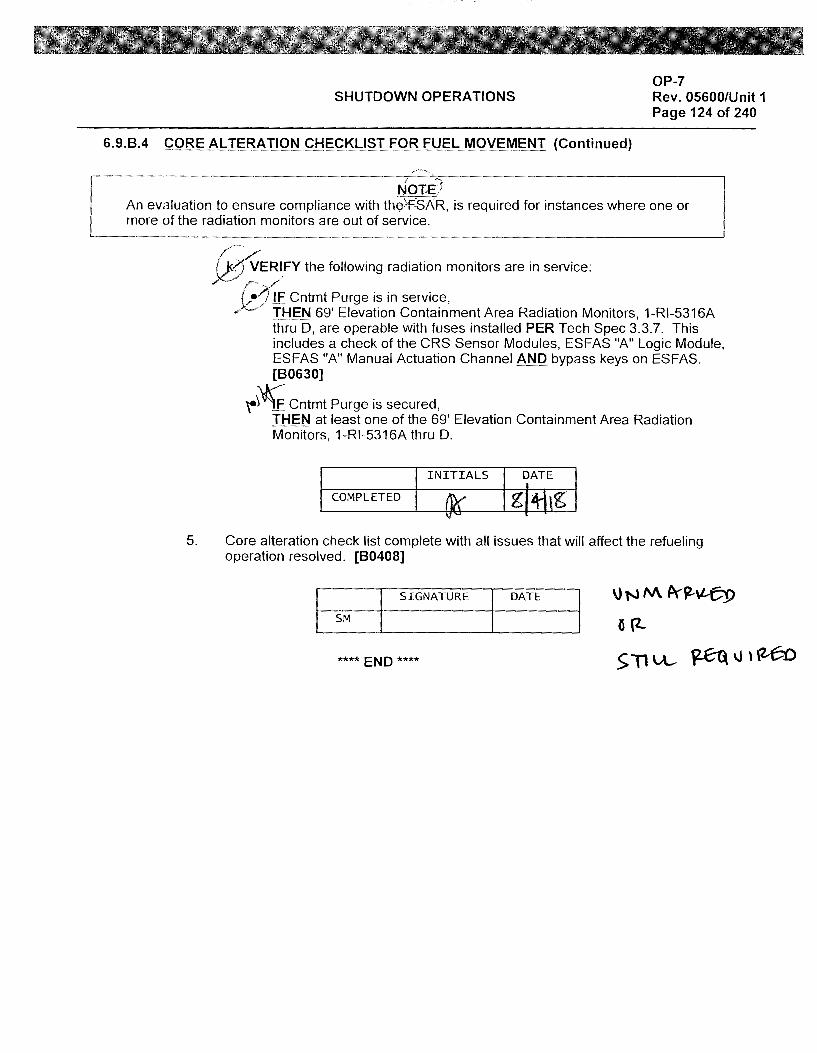
SHUTDOWN OPERATIONS OP-7 Rev. 05600/Unit 1 Page 124 of 240
6.9.8.4 CORE ALTERATION CHECKLIST FOR FUEL MOVEMENT (Continued)
NOTE1 An evaluation to ensure compliance with th~>F:SAR, is required for instances where one or more of the radiation monitors are out of service.
/ .. -·· /
~ERI_FY the following radiation monitors are in service:
(•1,F Cntmt Purge is in service, .)C:> THEN 69' Elevation Containment Area Radiation Monitors, 1-Rl-5316A
thru D, are operable with fuses installed PER Tech Spec 3.3.7. This includes a check of the CRS Sensor Modules, ES FAS "A" Logic Module, ESFAS "A" Manual Actuation Channel AND bypass keys on ESFAS. [80630]
~ ~ Cntmt Purge is secured, THEN at least one of the 69' Elevation Containment Area Radiation Monitors, 1-Rl-5316A thru D.
INITIALS DATE
COMPLETED
5. Core alteration check list complete with all issues that will affect the refueling operation resolved. [80408]
SIGNATURE
SM
**** END ****
DATE \)NM A'~\l--~
6 {2-
s Tl vL- ~ \J n'Z.-6.o
Examinee: -----
Calvert Cliffs Nuclear Power Plant
2018 NRC Initial Licensed Operator Exam
JPM-SRO Admin2

Appendix C Job Performance Measure Worksheet Form ES-C-1
Facility: Calvert Cliffs 1 & 2
Alternate Path: No
JPM Number: SRO Admin2
Task Number: 202.247
Task Title: Verify an Estimated Critical Condition Calculation
Task Standard:
This JPM is complete when several Estimated Critical Conditions have been reviewed, errors identified, and correct data entered on a blank line in Section 4 of NEOP-302 Attachment 2.
KIA Reference: 2.1.25 (4.2)
Method of Testing: Actual Performance-Classroom
Validation Time: 25 minutes
References and Tools Required:
1. NEOP-302, Estimated Critical Condition
2. NEOP-13, Technical Data Book (Unit-1-Rev 39)
3. Calculator
JPM Setup Instructions:
1. NEOP-302 placekeeping marks for steps 4.6, 6.1, 6.2, and 6.3 completed up to Step 6.3.2.
2. NEOP-302 Attachment 1, and Attachment 2 completed per attached.
3. Xenon Worth Calculator provided per attached.
SRO Admin2 Page 2 of 12
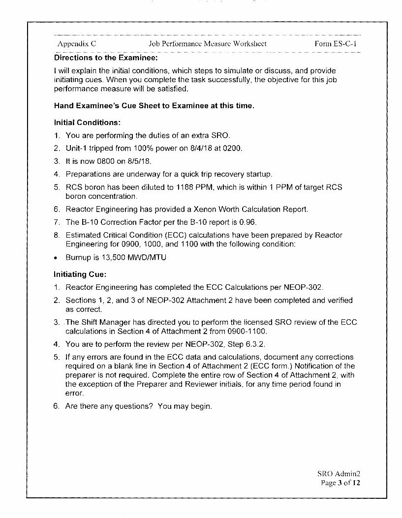
Appendix C Job Performance Measure Worksheet Form ES-C-1
Directions to the Examinee:
I will explain the initial conditions, which steps to simulate or discuss, and provide initiating cues. When you complete the task successfully, the objective for this job performance measure will be satisfied.
Hand Examinee's Cue Sheet to Examinee at this time.
Initial Conditions:
1. You are performing the duties of an extra SRO.
2. Unit-1 tripped from 100% power on 8/4/18 at 0200.
3. It is now 0800 on 8/5/18.
4. Preparations are underway for a quick trip recovery startup.
5. RCS boron has been diluted to 1188 PPM, which is within 1 PPM of target RCS boron concentration.
6. Reactor Engineering has provided a Xenon Worth Calculation Report.
7. The B-10 Correction Factor per the B-10 report is 0.96.
8. Estimated Critical Condition (ECG) calculations have been prepared by Reactor Engineering for 0900, 1000, and 1100 with the following condition:
• Burnup is 13,500 MWD/MTU
Initiating Cue:
1. Reactor Engineering has completed the ECG Calculations per NEOP-302.
2. Sections 1, 2, and 3 of NEOP-302 Attachment 2 have been completed and verified as correct.
3. The Shift Manager has directed you to perform the licensed SRO review of the ECG calculations in Section 4 of Attachment 2 from 0900-1100.
4. You are to perform the review per NEOP-302, Step 6.3.2.
5. If any errors are found in the ECG data and calculations, document any corrections required on a blank line in Section 4 of Attachment 2 (ECG form.) Notification of the preparer is not required. Complete the entire row of Section 4 of Attachment 2, with the exception of the Preparer and Reviewer initials, for any time period found in error.
6. Are there any questions? You may begin.
SRO Admin2 Page 3 of 12

Appendix C Job Performance Measure Worksheet Form ES-C-1
t-STEP STANDARD t- <(
ELEMENT <( en en z
::::>
TIME START:
CUE After Examinee reviews Cue Sheet, provide a calculator, NEOP-13 (Rev 39), the partially completed NEOP-302, and the Xenon Worth Calculation.
NEOP NEOP-302, Step 6.3, Estimated Critical Conditions.
Comment
SUBMIT Section 4 to a licensed NEOP SRO for review. Prior to 6.3.2 performing the review, the SRO
shall review Step 4.5.2
Comment
Some calculations performed in this procedure are originated by Reactor Engineering (RE) and
' then reviewed by a Senior
NEOP . Reactor Operator (SRO). If data 1 required as an input for a certain
4.5.2 calculation has been previously approved (i.e. previously signed off by an SRO), then it is not necessary to re-validate that data. When reviewing calculations, the SRO shall:
NEOP Verify that the previous critical 4.5.2 condition is correct if not
1 previously reviewed.
Identifies next step to complete is Step 6.3.2. - -
Determines Step 4.5.2 needs to be reviewed. - -
Determines that Input Data in Section 1 for previous critical condition was previously reviewed by an SRO as shown - -
by SRO signature on Attachment 2 Section 1.
SRO Admin2 Page 4 of 12

Appendix C Job Performance Measure Worksheet Form ES-C-1
STEP ELEMENT
Comment
NEOP INDEPENDENTLY VERIFY that
4.5.2 all recorded data and calculations in the section being
2 reviewed are accurate.
Comment
.... STANDARD .... <(
<( en en z
::J
Reviews data and calculations in Section 4 of Attachment 2. Determines the following:
0900 Xenon Worth value used is incorrect.
0900 CEA Worth is incorrect based on both Xenon Worth and math error.
0900 ECC CEA, Lower, and Upper Bound errors exist due to CEA Worth being incorrect.
1000 ECC data and calculations are correct.
1100 ECC data and calculations are correct.
- -
SROAdmin2 Page 5 of 12

Appendix C Job Performance Measure Worksheet Form ES-C-1
I-
STEP STANDARD I- <( ELEMENT <( en
en z ::,
Reviews data and calculations in Section 4 of Attachment 2. Determines the following:
0900 ECC Gp 5/Gp 4 are incorrect
VERIFY that the ECC Upper 0900 Lower CEA Bound pcm and Lower Bounds are is incorrect
NEOP calculated correctly AND the 0900 Lower CEA Bound Gp
4.5.2 established bounds are between 4/Gp 3 are incorrect 135 inches withdrawn on Reg - -
3 Group 5 and Zero Power POil, 0900 Upper CEA Bound pcm
if reviewing an estimated critical is incorrect
condition. 0900 Upper CEA Bound Gp 5 is incorrect
1000 Data and calculations are correct
1100 ECC data and calculations are correct.
Comment
CUE
I If notified of an error:
Document any corrections required on a blank line on the Section 4 of Attachment 2 (ECC form.)
Complete the entire row of Section 4 of Attachment 2, with the exception of the Preparer and Reviewer initials, for any time period found in error.
SR0Admin2 Page 6 of 12
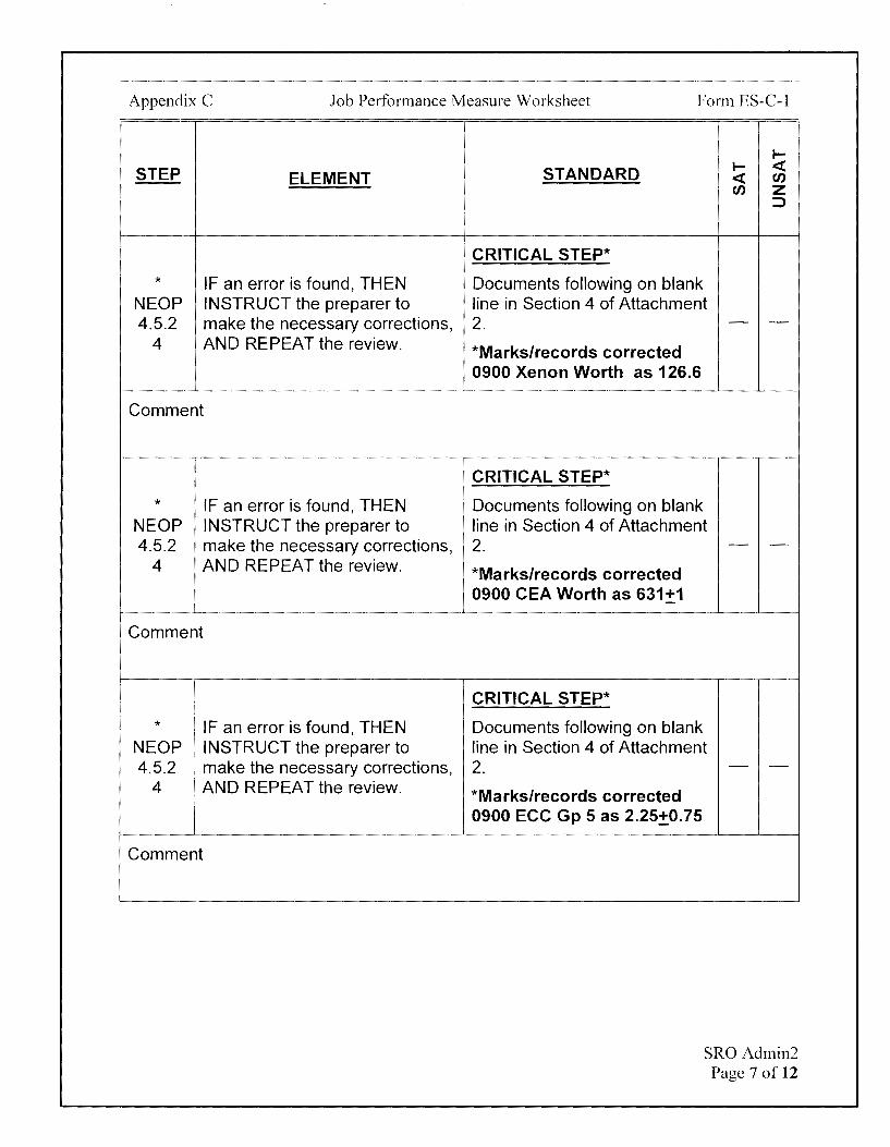
Appendix C Job Performance Measure Worksheet Form ES-C-1
STEP ELEMENT
* IF an error is found, THEN NEOP INSTRUCT the preparer to 4.5.2 make the necessary corrections,
4 AND REPEAT the review.
Comment
* IF an error is found, THEN NEOP INSTRUCT the preparer to 4.5.2 make the necessary corrections,
4 AND REPEAT the review.
Comment
I * I IF an error is found, THEN
NEOP !. INSTRUCT the preparer to 4.5.2 make the necessary corrections,
4 ) AND REPEAT the review.
I Comment
I-
STANDARD I- <i: <i: en en z
::::>
CRITICAL STEP*
Documents following on blank line in Section 4 of Attachment 2. - -*Marks/records corrected 0900 Xenon Worth as 126.6
CRITICAL STEP*
Documents following on blank line in Section 4 of Attachment 2. - -
*Marks/records corrected 0900 CEA Worth as 631.±1
CRITICAL STEP*
Documents following on blank line in Section 4 of Attachment 2. - -
*Marks/records corrected 0900 ECC Gp 5 as 2.25_±0.75
SRO Admin2 Page 7 of 12

Appendix C Job Performance Measure Worksheet Form ES-C-1
STEP ELEMENT
* IF an error is found, THEN NEOP INSTRUCT the preparer to 4.5.2 make the necessary corrections,
4 AND REPEAT the review.
Comment
* IF an error is found, THEN NEOP INSTRUCT the preparer to 4.5.2 make the necessary corrections,
4 AND REPEAT the review.
Comment
I
* I IF an error is found, THEN NEOP ' INSTRUCT the preparer to 4.5.2 make the necessary corrections,
4 AND REPEAT the review.
Comment
I-
STANDARD I- <( <( en en z
:::>
CRITICAL STEP*
Documents following on blank line in Section 4 of Attachment 2. - -*Marks/records corrected 0900 ECC Gp 4 as 92.25+0.75
CRITICAL STEP*
Documents following on blank line in Section 4 of Attachment 2. - -*Marks/records corrected 0900 Lower CEA Bound pcm as 1131+1
CRITICAL STEP*
Documents following on blank line in Section 4 of Attachment 2. - -*Marks/records corrected 0900 Lower CEA Bound Gp 4 as 21.75+0.75
SROAdmin2 Page 8 of 12

Appendix C Job Performance Measure Worksheet Form ES-C-1
STEP ELEMENT
* IF an error is found, THEN NEOP INSTRUCT the preparer to 4.5.2 make the necessary corrections,
4 AND REPEAT the review.
Comment
* IF an error is found, THEN NEOP INSTRUCT the preparer to 4.5.2 make the necessary corrections,
4 AND REPEAT the review.
Comment
' :
* IF an error is found, THEN NEOP INSTRUCT the preparer to 4.5.2 make the necessary corrections,
4 AND REPEAT the review.
Comment
I-
STANDARD I- c:i: c:i: en en z
::::>
CRITICAL STEP*
Documents following on blank line in Section 4 of Attachment 2. - -*Marks/records corrected 0900 Lower CEA Bound Gp 3 as 111.75+0.75
CRITICAL STEP*
Documents following on blank line in Section 4 of Attachment 2. - -*Marks/records corrected 0900 Upper CEA Bound pcm as 131+1
CRITICAL STEP*
Documents following on blank line in Section 4 of Attachment 2. - -*Marks/records corrected 0900 Upper CEA Bound Gp 5 as 99.75_:t0.75
SROAdmin2 Page 9 of 12

Appendix C Job Performance Measure Worksheet Form ES-C-1
I-
STEP STANDARD I- < ELEMENT < en
en z ::,
TERMINATING CUE:
This JPM is complete when several Estimated Critical Conditions have been reviewed, errors identified, and correct data entered on a blank line in Section 4 of NEOP-302 Attachment 2.
The Examinee is expected to end the JPM.
TIME STOP:
SRO Admin2 Page 10 of 12
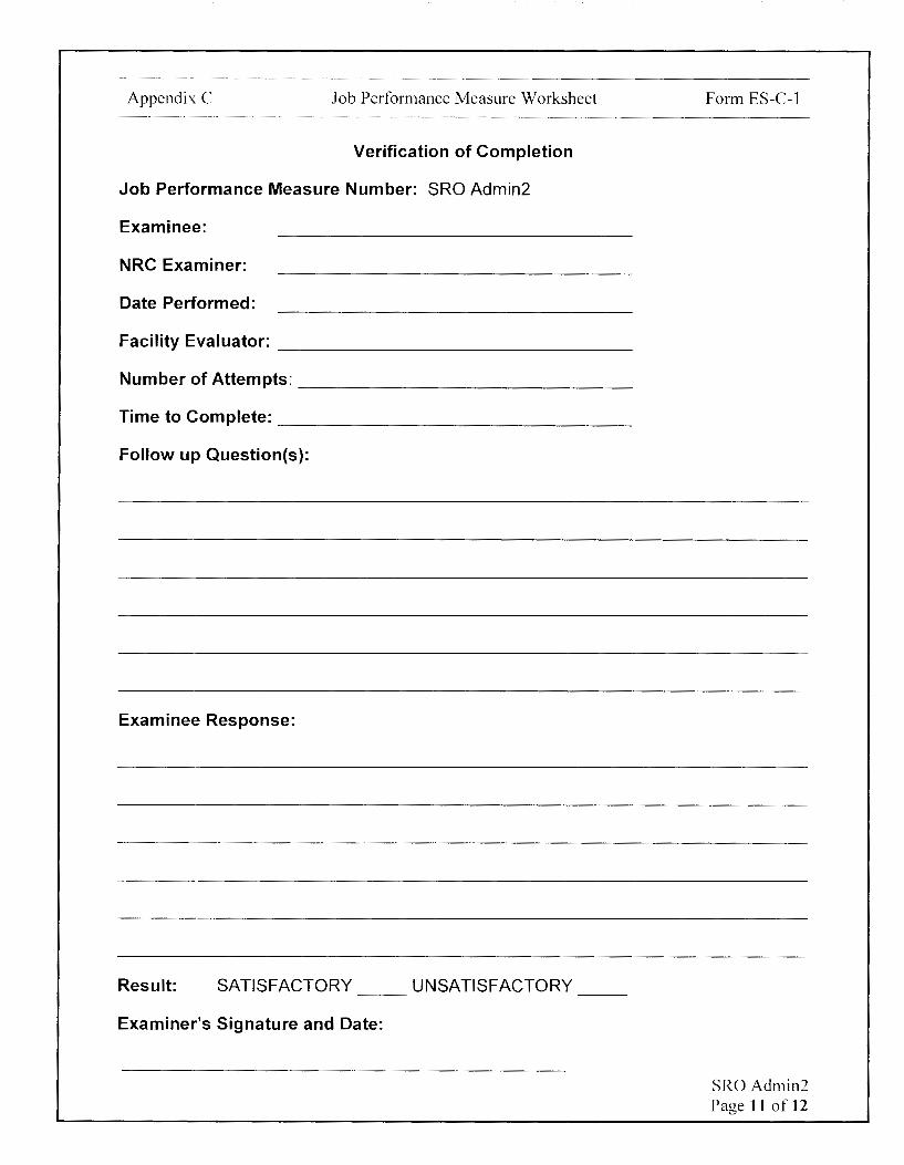
Appendix C Job Performance Measure Worksheet
Verification of Completion
Job Performance Measure Number: SRO Admin2
Examinee:
NRC Examiner:
Date Performed:
Facility Evaluator: ________________ _
Number of Attempts: ----------------Time to Complete: -----------------Follow up Question(s):
Examinee Response:
Result: SATISFACTORY UNSATISFACTORY -- --
Examiner's Signature and Date:
Form ES-C-1
SRO Admin2 Page 11 of 12
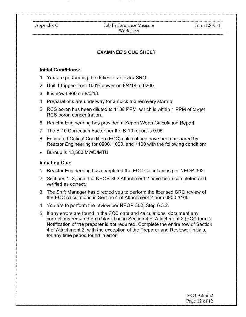
Appendix C
Initial Conditions:
Job Performance Measure Worksheet
EXAMINEE'S CUE SHEET
1. You are performing the duties of an extra SRO.
2. Unit-1 tripped from 100% power on 8/4/18 at 0200.
3. It is now 0800 on 8/5/18.
4. Preparations are underway for a quick trip recovery startup.
Form ES-C-1
5. RCS boron has been diluted to 1188 PPM, which is within 1 PPM of target RCS boron concentration.
6. Reactor Engineering has provided a Xenon Worth Calculation Report.
7. The 8-10 Correction Factor per the 8-10 report is 0.96.
8. Estimated Critical Condition (ECC) calculations have been prepared by Reactor Engineering for 0900, 1000, and 1100 with the following condition:
• 8urnup is 13,500 MWD/MTU
Initiating Cue:
1. Reactor Engineering has completed the ECC Calculations per NEOP-302.
2. Sections 1, 2, and 3 of NEOP-302 Attachment 2 have been completed and verified as correct.
3. The Shift Manager has directed you to perform the licensed SRO review of the ECC calculations in Section 4 of Attachment 2 from 0900-1100.
4. You are to perform the review per NEOP-302, Step 6.3.2.
5. If any errors are found in the ECC data and calculations, document any corrections required on a blank line in Section 4 of Attachment 2 (ECC form.) Notification of the preparer is not required. Complete the entire row of Section 4 of Attachment 2, with the exception of the Preparer and Reviewer initials, for any time period found in error.
SRO Admin2 Page 12 of 12
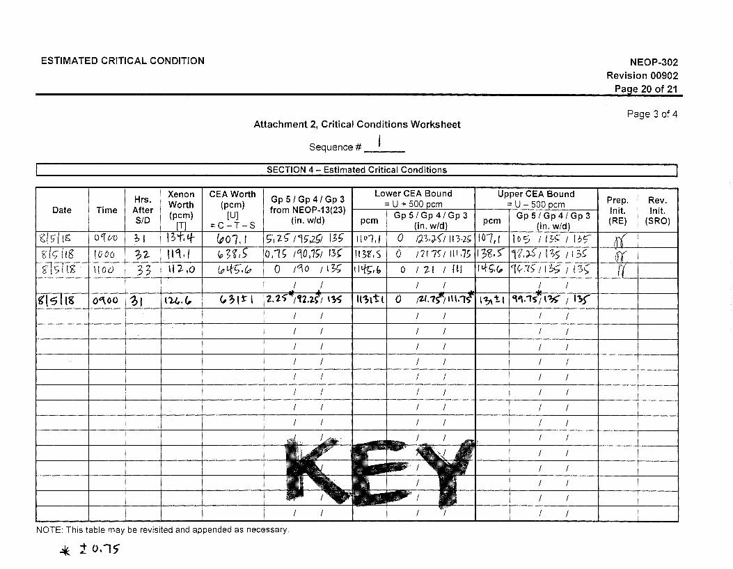
ESTIMATED CRITICAL CONDITION
Attachment 2, Critical Conditions Worksheet
Sequence# __ _
SECTION 4 - Estimated Critical Conditions
Hrs. Xenon CEA Worth Gp 5 / Gp 4 / Gp 3
Lower CEA Bound Worth (pcm) = U + 500 ocm
Date I Time I After (pcm) [UJ from NEOP-13(23)
Gp 5 / Gp 4 / Gp 3 SID [T] =C-T-S (in. w/d) pcm
(in. w/d) 0 'f UV ;1 I 3t, tf- (po,, I s-, 2~ ns-,29 1_;~ 1[01,1 0 f'J.""1,"J.ft ,n.i; 1000 ;2 II'\ I I <o~<l1S 0.1~ 1°i,0,1S1 13, 113B' I'S 0 ;21.7<:; 111.75
\tOU 33 \11,0 (p ttS",4, 0 ;qo /I~; 11%,!, 0 I if / I!/
I I I I
!l5 I tK I o"'oo 1 i, 1tu.<, l <,?It I 12, t S-"/12.2.(1 11~ 11'?,t t l 0 /Z.f.'7('°; 1\l,1s' I I I I I
I I I I
I I I I
I I I I
I I I I
I I I I
I I I I
I I I I
I I I I
NOTE: This table may be revisited and appended as necessary.
'*- 1 o.-,,
Upper CEA Bound = U - 500 pcm
Gp 5 / Gp 4 / Gp 3 pcm
(in. w/d)
10"7, I I o 5 I I 3''> I I ;,'.7 ( 3'6,) , e. ;;is 1 1 :;5 1 , 3~ I 4'~.<, 4<r ~le I~ .., " . , ., I I l ::oS,
I I ... 17\'tl 'V\.,s~i I'?> / 1,.(
I I
I I
I I
I I
I I
I I
I I
I I
I I
I I
I I
I
I
I I
NEOP-302 Revision 00902
Paoe 20 of 21
Page 3 of 4
Prep. Rev. lnit. lnit. (RE) (SRO)
Examinee:
Calvert Cliffs Nuclear Power Plant
2018 NRC Initial Licensed Operator Exam
JPM-SRO Admin3
Appendix C Job Performance Measure Worksheet Form ES-C-1
Facility: Calvert Cliffs 1 & 2
Alternate Path: No
Task Number: 210.003
Task Title: Perform the initial review of a completed STP
Task Standard:
JPM Number: SRO Admin3
This JPM is complete when STP 0-73H-2 Acceptance Criteria for Step 6.2 is completed and any required actions are identified.
KIA Reference: 2.2.12 (3.7/4.1)
Method of Testing: Actual Performance-Classroom
Validation Time: 14 minutes
References and Tools Required:
1. STP 0-73H-2 (Rev 13)
1. Tech Spec 3.7.3
JPM Setup Instructions:
1. STP 0-73H-2 placekeeping marks for Steps 4.0 and 5.0 completed.
2. Tables and data in Step 6.2 completed per the attached.
3. STP 0-73H-2 placekeeping marks for Step 6.2 completed up to 6.2.BC.
4. WC-AA-111 requirements in Step 6.2.BC removed.
5. Attachment 1 of STP 0-73H-2 included.
SRO Admin3 Page 2 of 11
Appendix C Job Performance Measure Worksheet Form ES-C-1
Directions to the Examinee:
I will explain the initial conditions, which steps to simulate or discuss, and provide initiating cues. When you complete the task successfully, the objective for this job performance measure will be satisfied.
Hand Examinee's Cue Sheet to Examinee at this time.
Initial Conditions:
1. You are performing the duties of the Unit-2 Unit Supervisor.
2. 21 AFW Pump is currently aligned for Automatic Operation and 22 AFW Pump is currently aligned for Standby Operation.
3. STP 0-73H-2 is in progress. Only Section 6.2, 23 and 13 AFW Pump Flow Verification, is being performed.
4. Section 6.2 of STP 0-73H-2 has been completed with exception of Acceptance Criteria review.
Initiating Cue:
1. You are to perform the Supervisory Review by completing Step 6.2.BC, Acceptance Criteria.
1. Document any further actions required, if any, as a result of the Supervisory Review below. Notifications, if required, are not to be made verbally. Notifications, if required, should be documented below as well.
2. Are there any questions? You may begin.
SRO Admin3 Page 3 of 11

Appendix C Job Performance Measure Worksheet Form ES-C-1
I-
STEP STANDARD I- <C ELEMENT <C en
en z :::>
TIME START:
CUE After Examinee reviews Cue Sheet, provide the partially completed STP 0-73H-2 and a calculator.
STP STP 0-73H-2, Step 6.2.BC, Identifies next step to Acceptance Criteria. complete is Step 6.2.BC. - -
Comment
6.2 Performance of this step constitutes a supervisor review. Actual observation
BC of equipment response by the SRO performing this review is not required.
1 Answering YES to a step below signifies that the referenced step has been
NOTE completed and signed off by a qualified operator other than the SRO reviewer and that the actual equipment response is acceptable and valid.
I CRITICAL STEP* Were 23 AFW PP INBD AND Reviews vibration
* OUTBD bearing vibration accelerometer readings in 6.2 • accelerometer readings less Step 6.2.R. BC than ACTION RANGE limit as - -1 recorded in Step 6.2.R? (NIA if Determines all readings were
NOT tested in step 6.2.R) less than ACTION RANGE.
*Circles YES
Comment
SRO Admin3 Page 4 of 11
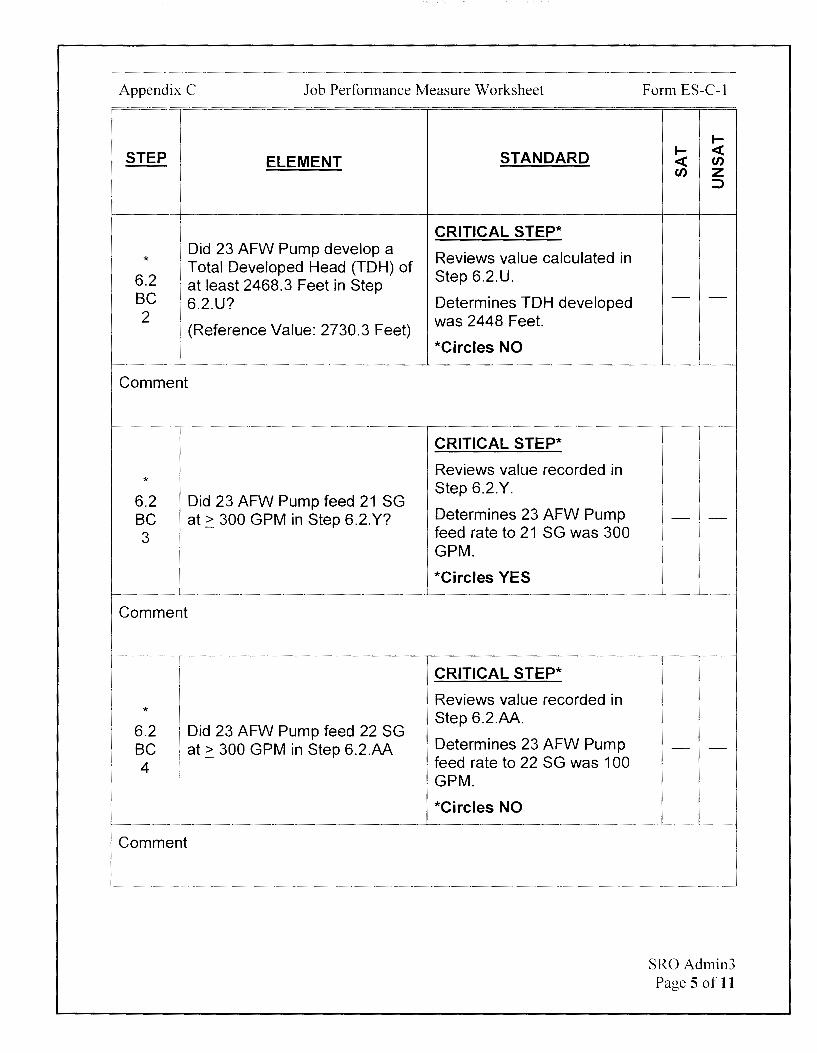
Appendix C Job Performance Measure Worksheet
STEP ELEMENT STANDARD
CRITICAL STEP*
* Did 23 AFW Pump develop a
Reviews value calculated in
6.2 Total Developed Head (TOH) of
Step 6.2.U. at least 2468.3 Feet in Step
BC 6.2.U? Determines TOH developed 2 was 2448 Feet.
(Reference Value: 2730.3 Feet) *Circles NO
Comment
CRITICAL STEP*
Reviews value recorded in *
6.2 Did 23 AFW Pump feed 21 SG Step 6.2.Y.
BC at~ 300 GPM in Step 6.2.Y? Determines 23 AFW Pump
3 feed rate to 21 SG was 300 GPM.
*Circles YES
Comment
CRITICAL STEP*
Reviews value recorded in *
6.2 Did 23 AFW Pump feed 22 SG Step 6.2.AA.
BC at~ 300 GPM in Step 6.2.AA Determines 23 AFW Pump ' feed rate to 22 SG was 100 4 i
GPM.
*Circles NO
Comment
Form ES-C-1
I-I- <( <( en en z
::::,
- -
- -
- -
SRO Admin3 Page 5 of 11
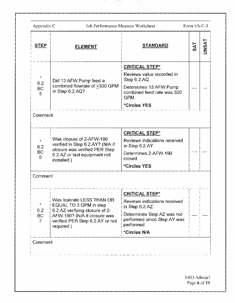
Appendix C Job Performance Measure Worksheet Form ES-C-1
STEP ELEMENT
* 6.2
Did 13 AFW Pump feed a
BC combined flowrate of ~300 GPM
5 in Step 6.2.AQ?
Comment
* . Was closure of 2-AFW-190
6.2 ! verified in Step 6.2.AY? (NIA if
BC ' closure was verified PER Step
6 6.2.AZ or test equipment not
1 installed.)
I
Comment
Was leakrate LESS THAN OR * EQUAL TO 3 GPM in step
6.2 6.2.AZ verifying closure of 2-BC AFW-190? (N/A if closure was 7 verified PER Step 6.2.A Y or not
required.)
Comment
STANDARD
CRITICAL STEP*
Reviews value recorded in Step 6.2.AQ.
Determines 13 AFW Pump combined feed rate was 300 GPM.
*Circles YES
CRITICAL STEP*
Reviews indications received in Step 6.2.A Y.
Determines 2-AFW-190 closed.
*Circles YES
CRITICAL STEP*
Reviews indications received in Step 6.2.AZ.
Determines Step AZ was not performed since Step A Y was performed.
*Circles NIA
I-I- <C <C en en z
:::>
- -
- -
- -
SRO Admin3 Page 6 of 11

Appendix C Job Performance Measure Worksheet Form ES-C-1
I-
STEP STANDARD I- <( ELEMENT <( t./J
t./J z :::::>
CRITICAL STEP*
Reviews answers in 6 .2 .BC .1-*
This test is considered 7. 6.2
satisfactory if YES OR NIA was BC Determines Steps 6.2.BC.2 - -B answered in the steps above. and 6.2.BC.4 were answered
NO.
*Circles UNSAT
Comment
6.2 BC IF unsat, THEN: Determines step is applicable. - -Ba
Comment
CUE If Examinee is attempting to notify the Shift Manager (SM), record any
i further actions required on Cue Sheet.
* 6.2 CRITICAL STEP* BC
NOTIFY SM. *Marks/records action of Ba notifying the Shift Manager, 1st or similar wording.
Bullet
Comment
- -
SRO Admin3 Page 7 of 11
Appendix C Job Performance Measure Worksheet Form ES-C-1
.... STEP STANDARD
.... <C ELEMENT <C u,
u, z :::)
* CRITICAL STEP* 6.2 * Marks/records action of BC DECLARE affected equipment declaring the 23 AFW Pump, Ba inoperable. the motor-driven pump, - -
2nd inoperable, or similar Bullet wording.
Comment
CUE After Examinee determines Tech Spec actions are required, provide Tech Spec 3.7.3.
* I 6.2 I
BC TAKE action as required by Ba Technical Specifications. 3rd !
Bullet
Comment
CRITICAL STEP*
Determines TS 3.7.3 Condition B applies.
* Marks/records action of aligning the 22 AFW Pump, the standby steam-driven pump, for Automatic Operation within 72 hours, - -
or similar wording.
*Marks/records action of returning 23 AFW Pump, the motor-driven pump, to OPERABLE status within 7 days, or similar wording.
SRO Admin3 Page 8 of 11
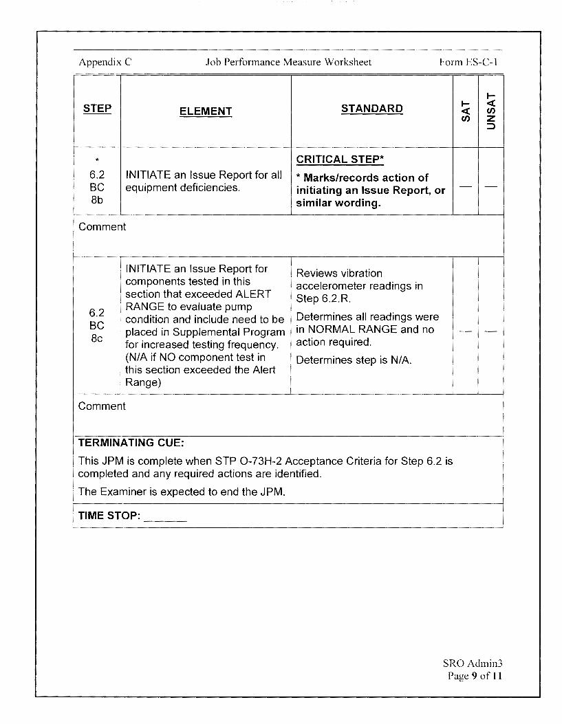
Appendix C Job Performance Measure Worksheet Form ES-C-1
I-
STEP STANDARD I- <( ELEMENT <( en
en z ::::>
* CRITICAL STEP* 6.2 INITIATE an Issue Report for all * Marks/records action of BC equipment deficiencies. initiating an Issue Report, or - -8b similar wording.
Comment
INITIATE an Issue Report for Reviews vibration components tested in this accelerometer readings in section that exceeded ALERT Step 6.2.R.
6.2 RANGE to evaluate pump
Determines all readings were condition and include need to be BC
placed in Supplemental Program in NORMAL RANGE and no - -Be
for increased testing frequency. action required.
(NIA if NO component test in Determines step is NIA. this section exceeded the Alert
'
I Range)
Comment
TERMINATING CUE:
This JPM is complete when STP 0-73H-2 Acceptance Criteria for Step 6.2 is completed and any required actions are identified.
The Examiner is expected to end the JPM.
TIME STOP:
SRO Admin3 Page 9 of 11
Appendix C Job Performance Measure Worksheet
Verification of Completion
Job Performance Measure Number: SRO Admin3
Examinee:
NRC Examiner:
Date Performed:
Facility Evaluator: ________________ _
Number of Attempts: _______________ _
Time to Complete: -----------------Follow up Question(s}:
Examinee Response:
Result: SATISFACTORY UNSATISFACTORY -- --
Examiner's Signature and Date:
Form ES-C-1
SRO Admin3 Page 10 of 11
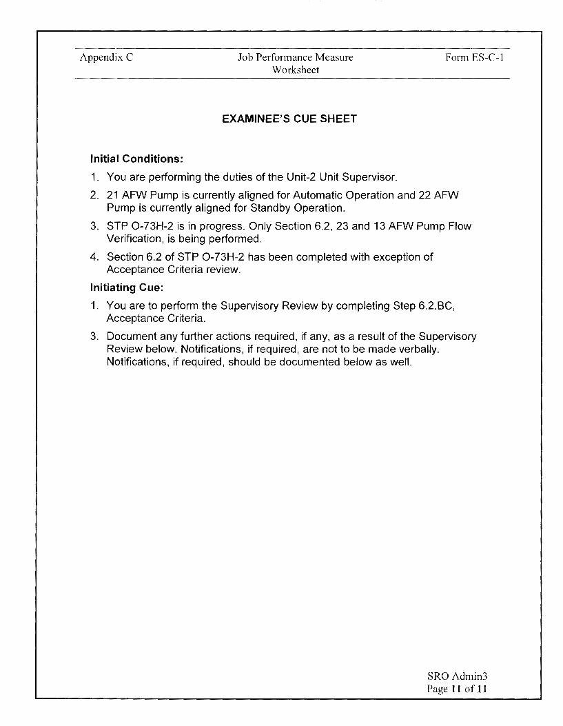
Appendix C
Initial Conditions:
Job Performance Measure Worksheet
EXAMINEE'S CUE SHEET
1. You are performing the duties of the Unit-2 Unit Supervisor.
Form ES-C-1
2. 21 AFW Pump is currently aligned for Automatic Operation and 22 AFW Pump is currently aligned for Standby Operation.
3. STP 0-73H-2 is in progress. Only Section 6.2, 23 and 13 AFW Pump Flow Verification, is being performed.
4. Section 6.2 of STP 0-73H-2 has been completed with exception of Acceptance Criteria review.
Initiating Cue:
1. You are to perform the Supervisory Review by completing Step 6.2.BC, Acceptance Criteria.
3. Document any further actions required, if any, as a result of the Supervisory Review below. Notifications, if required, are not to be made verbally. Notifications, if required, should be documented below as well.
SR0Admin3 Page 11 of 11

6.2
AFW PUMP LARGE FLOW TEST
23 AND 13 AFW PUMP FLOW VERIFICATION [82117] (Continued)
BC ACCEPTANCE CRITERIA:
NOTE
STP 0-73H-2 Rev. 13/Unit 2 Page 59 of 120
INITIALS
Performance of this step constitutes a supervisory review. Actual observation of equipment response by the SRO performing this review is not required. Answering YES to a step below signifies that the referenced step has been completed and signed off by a qualified operator other than the SRO reviewer and that the actual equipment response is acceptable and valid.
1. Were 23 AFW PP INBD AND OUTBD bearing vibration accelerometer readings less than ACTION RANGE limit as recorded in Step 6.2.R? (NIA if NOT tested in step 6.2.R)
2. Did 23 AFW Pump develop a Total Developed Head (TOH) of at least 2468.3 Feet and no greater than 2812.2 Feet in Step 6.2.U? (Reference Value: 2730.3 Feet)
3. Did 23 AFW PP feed 21 SG at ~300 GPM in Step 6.2.Y?
A SRO
SRO
NO one) SRO
4. Did 23 AFW PP feed 22 SG at ~300 GPM in Step 6.2.AA?
YES~ (circl~)
5. Did 13 AFW PP feed a combined flowrate of ~300 GPM in Step 6.2.AQ.
6. Was closure of 2-AFW-190 verified in Step 6.2.A Y ? (NIA if closure was verified PER Step 6.2.AZ or test equipment not installed.)
SRO
SRO
A SRO
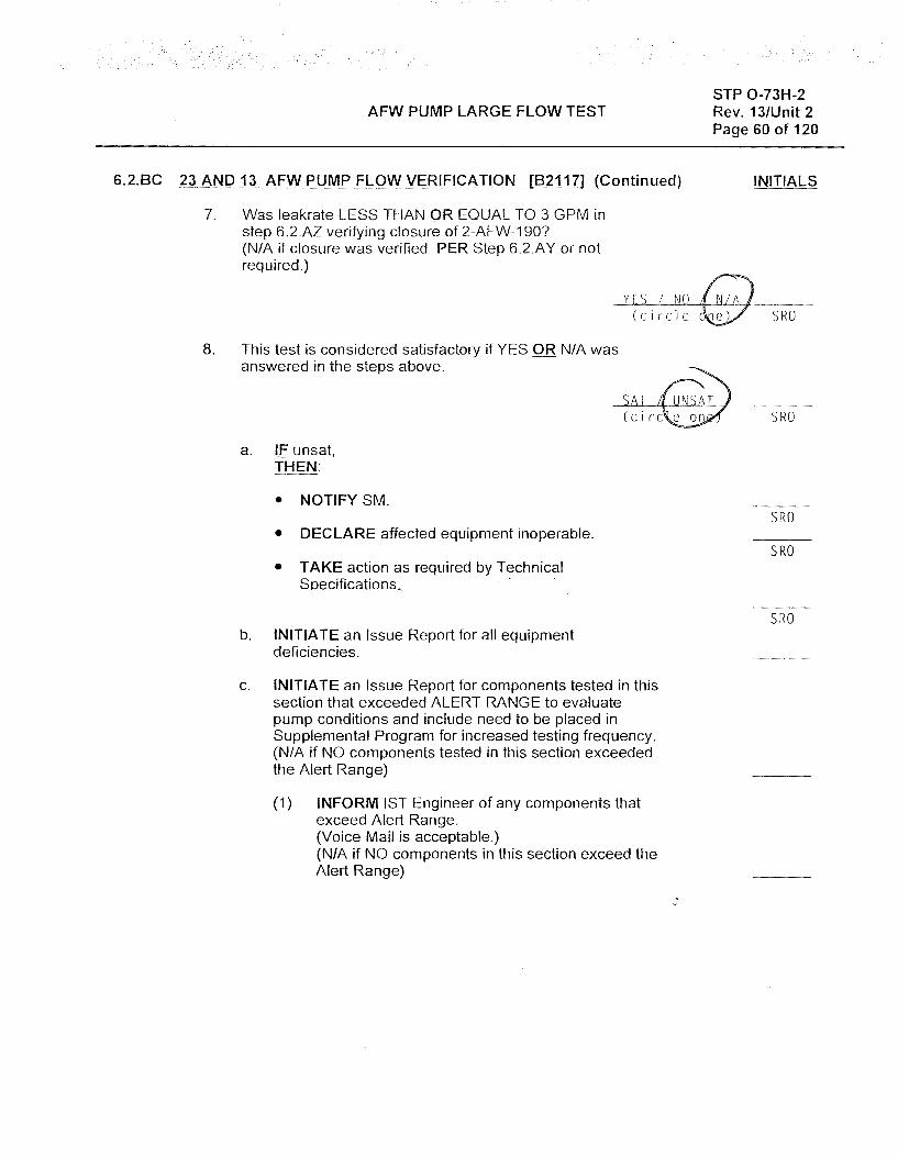
AFW PUMP LARGE FLOW TEST
6.2.BC _23 AND 13 AFW PUMP FLOW VERIFICATION [82117] (Continued)
7. Was leakrate LESS THAN OR EQUAL TO 3 GPM in step 6.2.AZ verifying closure of 2-AFW-190? (N/A if closure was verified PER Step 6.2.A Y or not required.)
STP 0-73H-2 Rev. 13/Unit 2 Page 60 of 120
INITIALS
YES LJiQ Q __ _ (circle~ SRO
8. This test is considered satisfactory if YES ORN/A was answered in the steps above.
a. IF unsat, THEN:
• NOTIFY SM.
• DECLARE affected equipment inoperable.
• TAKE action as required by Technical Specifications.
b. INITIATE an Issue Report for all equipment deficiencies.
c. INITIATE an Issue Report for components tested in this section that exceeded ALERT RANGE to evaluate pump conditions and include need to be placed in Supplemental Program for increased testing frequency. (NIA if NO components tested in this section exceeded the Alert Range)
(1) INFORM 1ST Engineer of any components that exceed Alert Range. (Voice Mail is acceptable.) (NIA if NO components in this section exceed the Alert Range)
SRO
SRO
SRO
SRO
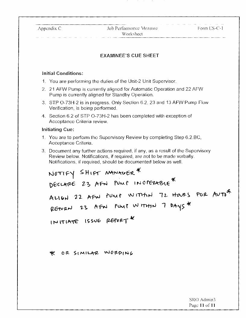
Appendix C
Initial Conditions:
Job Performance Measure Worksheet
EXAMINEE'S CUE SHEET
·--·-~------~---·-- ·-
Form ES-C-1
1. You are performing the duties of the Unit-2 Unit Supervisor.
2. 21 AFW Pump is currently aligned for Automatic Operation and 22 AFW Pump is currently aligned for Standby Operation.
3. STP 0-73H-2 is in progress. Only Section 6.2, 23 and 13 AFW Pump Flow Verification, is being performed.
4. Section 6.2 of STP 0-73H-2 has been completed with exception of Acceptance Criteria review.
Initiating Cue:
1. You are to perform the Supervisory Review by completing Step 6.2.BC, Acceptance Criteria.
3. Document any further actions required, if any, as a result of the Supervisory Review below. Notifications, if required, are not to be made verbally. Notifications, if required, should be documented below as well.
~ H t f1'-' /\NrN ,w f;;ft * Z ~ ~r,J f lJM f I N O f~t,E 1E
A. l..-\ C, .J 1, 2 A-fvJ ? l) A.A f v,.J 11"\1', t,J
(2..G--iv.i. ..J '2.-~ ft- f°w PVM f vJ 1Tl-t1 ,J
t N l'T I~ l S S\lf;- (2-Gfo fZ-t ~
SRO Admin3 Page 11 of 11

AFW PUMP LARGE FLOW TEST
6.2 23 AND 13 AFW PUMP FLOW VERIFICATION [82117) (Continued)
r---· lE
STP 0-73H-2 Rev. 13/Unit 2 Page 48 of 120
INITIALS
~ottling of gauge isolation valves to dam en gauge needle oscillations is permissible.
w~HEN 23 AFW Pump has been running for at least 5 minutes with an average flowrate of 420 (410-425) GPM (5 minute average as read on the Ultrasonic Flowmeter), r( THEN RECORD the following data:
PARAMETER ACCEPTABLE RANGE READING
suction Pressure N/A [SIG (2-PI-4542) j..l ,'1
Discharge Pressure N/A fOll ·1 PSIG (2-PI-4544)
Pump suction Pipe N/A '10.r Temperature "F
Pump suet Flowrate 420 GPM 'tli,1 (5 minute average) ( 410-42 5) GPM
21 S/G Flow controller io output signal N/A %
(2-FIC-4525A)
22 S/G Flow Controller (, 1,t;' output signal N/A %
(2-FIC-4535A)
21 Steam Generator N/A 180 Pressure (2-PI-1013A) PSIA
22 Steam Generator N/A iio Pressure (2-PI-1023A) PSIA
23 AFW PP Recirc N/A flowrate Jj..&f. ~ GPM
(5 minute average)
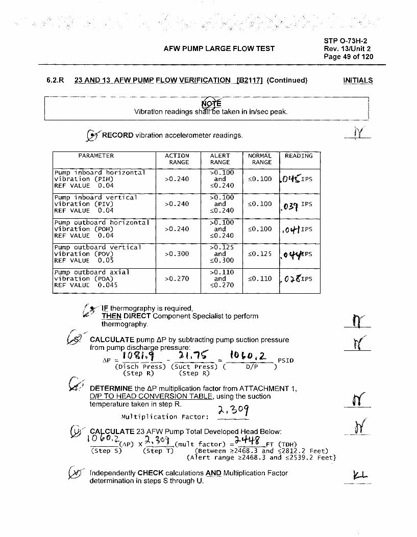
AFW PUMP LARGE FLOW TEST
6.2.R 23 AND 13 AFW PUMP FLOW VERIFICATION [82117] {Continued)
Vibration readings sh e taken in in/sec peak.
W RECORD vibration accelerometer readings.
PARAMETER ACTION ALERT NORMAL RANGE RANGE RANGE
Pump inboard horizontal >0.100 vibration (PIH) >0.240 and $0.100 REF VALUE 0.04 :,:;0.240
Pump inboard vertical >0.100 vibration (PIV) >0.240 and :s;0.100 REF VALUE 0.04 :,:;0.240
Pump outboard horizontal >0.100 vibration (POH) >0.240 and :s;0.100 REF VALUE 0.04 :s;0.240
Pump outboard vertical >0.125 vibration (POV) >0.300 and $0.125 REF VALUE 0.05 :,:;0.300
Pump outboard axial >0.110 vibration (POA) >0.270 and :s;0.110 REF VALUE 0.045 :,:;0.270
IF thermography is required, THEN DIRECT Component Specialist to perform thermography.
READING
.Ott(IPS
.031 IPS
,O"f'iIPS
,OWPS
~ 0 ;).g'IPS
CALCULATE pump ~p by subtracting pump suction pressure from pump discha']e pressure:
L'iP = IOil,1 _ ll,1~ = 101,0,2. PSID (Disch Press) (Suet Press) ( D/P )
(Step R) (Step R)
DETERMINE the ~p multiplication factor from ATTACHMENT 1, D/P TO HEAD CONVERSION TABLE, using the suction temperature taken in step R.
Multiplication Factor:
@,.,, CALCULATE 23 AFW Pump Total Developed Head Below:
lO(f.0,'2.(L'iP) x;l.,1°l (mult factor) =d'-"tffg' FT (TOH)
STP 0-73H-2 Rev. 13/Unit 2 Page 49 of 120
INITIALS
(Step S) (Step T) (Between ~2468.3 and :s:;2812.2 Feet) (Alert range ~2468.3 and :,:;2539.2 Feet}
Independently CHECK calculations AND Multiplication Factor determination in steps S through U.
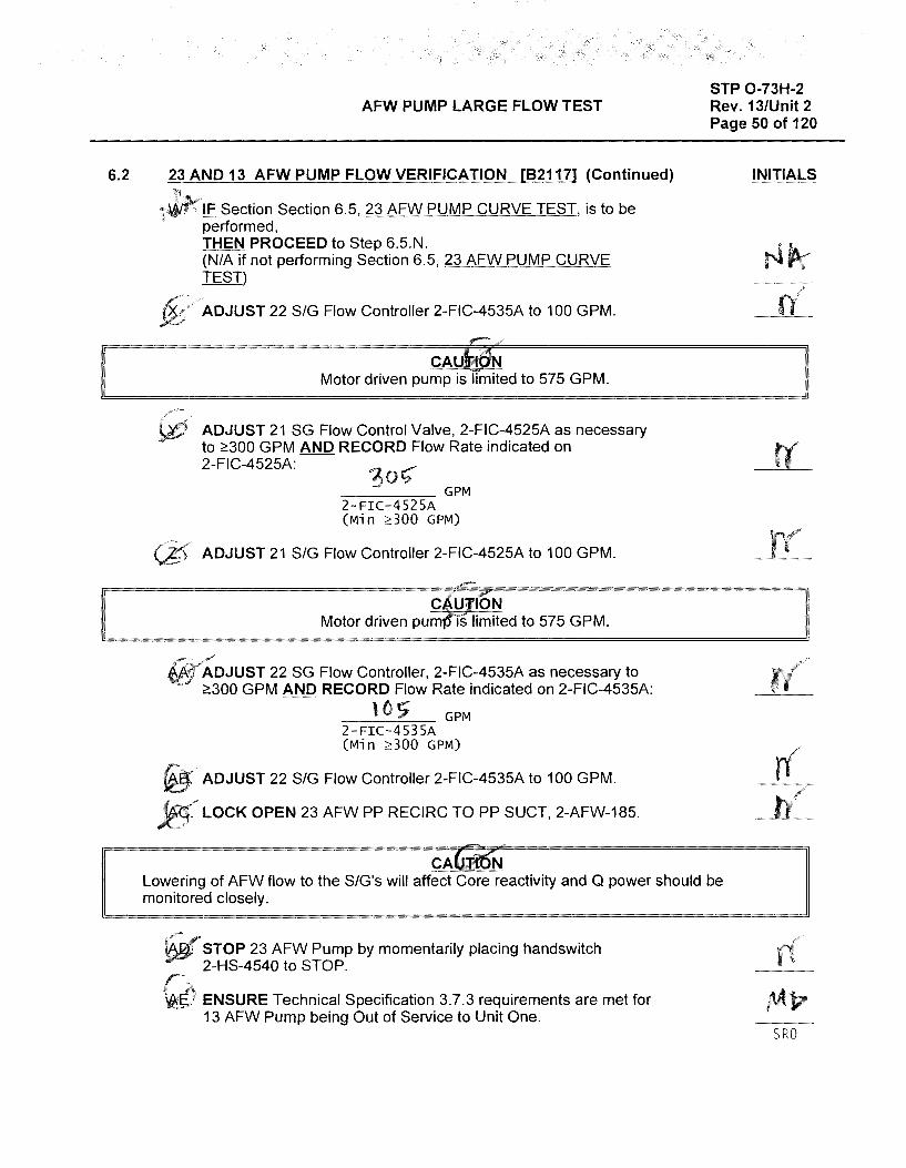
6.2
AFW PUMP LARGE FLOW TEST
23 AND 13 AFW PUMP FLOW VERIFICATION (82117] (Continued)
IF Section Section 6.5, 23 AFW PUMP CURVE TEST, is to be performed, THEN PROCEED to Step 6.5.N. (NIA if not performing Section 6.5, 23 AFW PUMP CURVE TEST)
ADJUST 22 SIG Flow Controller 2-FIC-4535A to 100 GPM.
CA Motor driven pump is limited to 575 GPM.
ADJUST 21 SG Flow Control Valve, 2-FIC-4525A as necessary to 2!300 GPM AND RECORD Flow Rate indicated on 2-FIC-4525A:
----- GPM 2-FIC-4525A (Min 2:300 GPM)
ADJUST 21 SIG Flow Controller 2-FIC-4525A to 100 GPM.
STP 0-73H-2 Rev. 13/Unit 2 Page 50 of 120
INITIALS
II c 'u (oN Motor driven pum i's limited to 575 GPM.
======i
/" ADJUST 22 SG Flow Controller, 2-FIC-4535A as necessary to 2!300 GPM AND RECORD Flow Rate indicated on 2-FIC-4535A:
l O !? ----- GPM 2-FIC-4535A (Min ;:,:300 GPM)
ADJUST 22 SIG Flow Controller 2-FIC-4535A to 100 GPM.
LOCK OPEN 23 AFW PP RECIRC TO PP SUCT, 2-AFW-185.
CACJi.ir>N Lowering of AFW flow to the S/G's will affect Core reactivity and Q power should be monitored closely.
STOP 23 AFW Pump by momentarily placing handswitch 2-HS-4540 to STOP. r-_
~_g} ENSURE Technical Specification 3.7.3 requirements are met for 13 AFW Pump being Out of Service to Unit One.
SRO
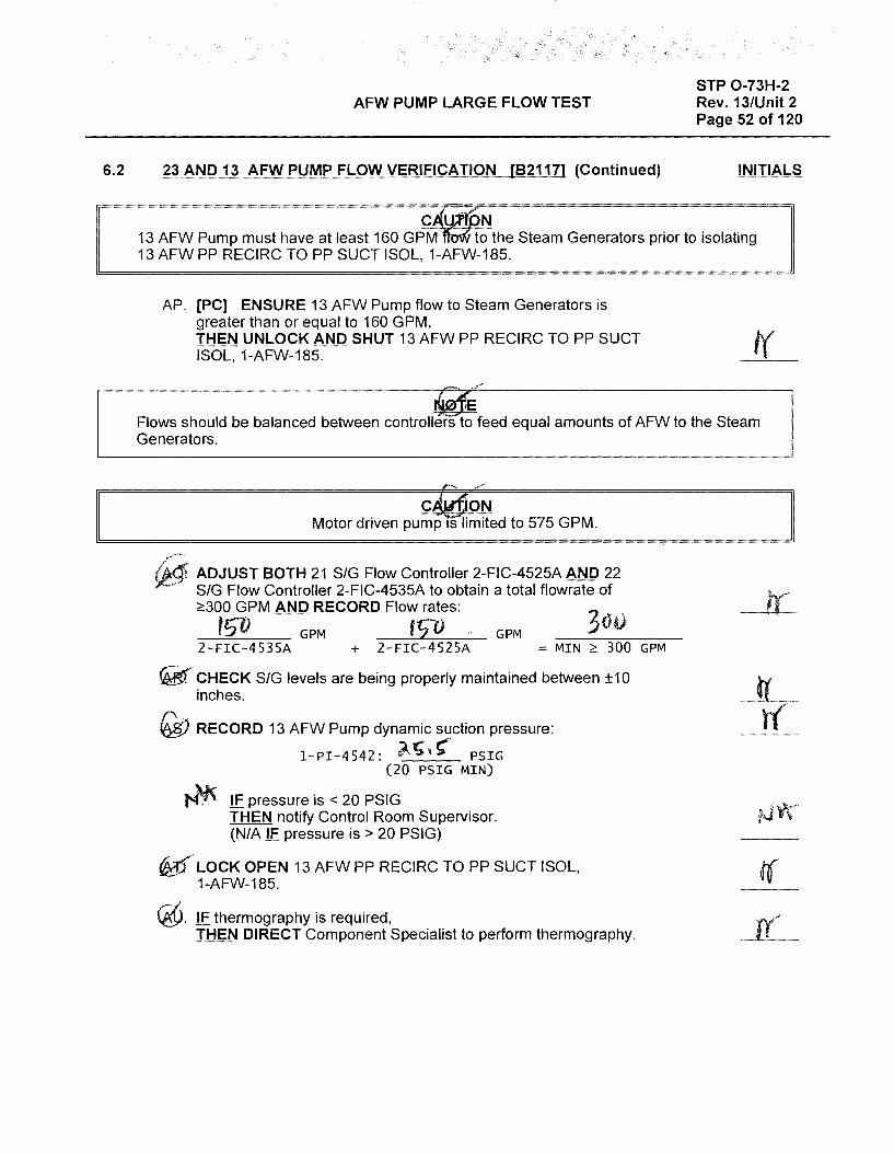
6.2
AFW PUMP LARGE FLOW TEST
23 AND 13 AFW PUMP FLOW VERIFICATION [821171 (Continued)
C , N
STP 0-73H-2 Rev. 131Unit 2 Page 52 of 120
INITIALS
W Pump must have at least 160 GPM to the Steam Generators prior to isolating WPP RECIRC TO PP SUCT !SOL, 1-AFW-185.
AP. [PC] ENSURE 13 AFW Pump flow to Steam Generators is greater than or equal to 160 GPM, THEN UNLOCK AND SHUT 13 AFW PP RECIRC TO PP SUCT ISOL, 1-AFW-185. I(
Flows should be balanced between controllers to feed equal amounts of AFW to the Steam Generators.
ck.rlloN Motor driven pump Tslimited to 575 GPM.
/'.~--
5,t<ti ADJUST BOTH 21 SIG Flow Controller 2-FIC-4525A AND 22 • SIG Flow Controller 2-FIC-4535A to obtain a total flowrate of
:2:300 GPM AND RECORD Flow rates:
t5D -GPM f sv GPM 2-FIC-4535A + 2-FIC-4525A =MIN~ 300 GPM
~-CHECK SIG levels are being properly maintained between ±10 inches.
~ RECORD 13 AFW Pump dynamic suction pressure:
1-PI-4542: /-.~t" PSIG (20 PSIG MIN)
~· IF pressure is < 20 PSIG THEN notify Control Room Supervisor. (NIA IF pressure is > 20 PSIG)
~( LOCK OPEN 13 AFW PP RECIRC TO PP SUCT ISOL, 1-AFW-185.
@. lE thermography is required, JHEN DIRECT Component Specialist to perform thermography.
t(
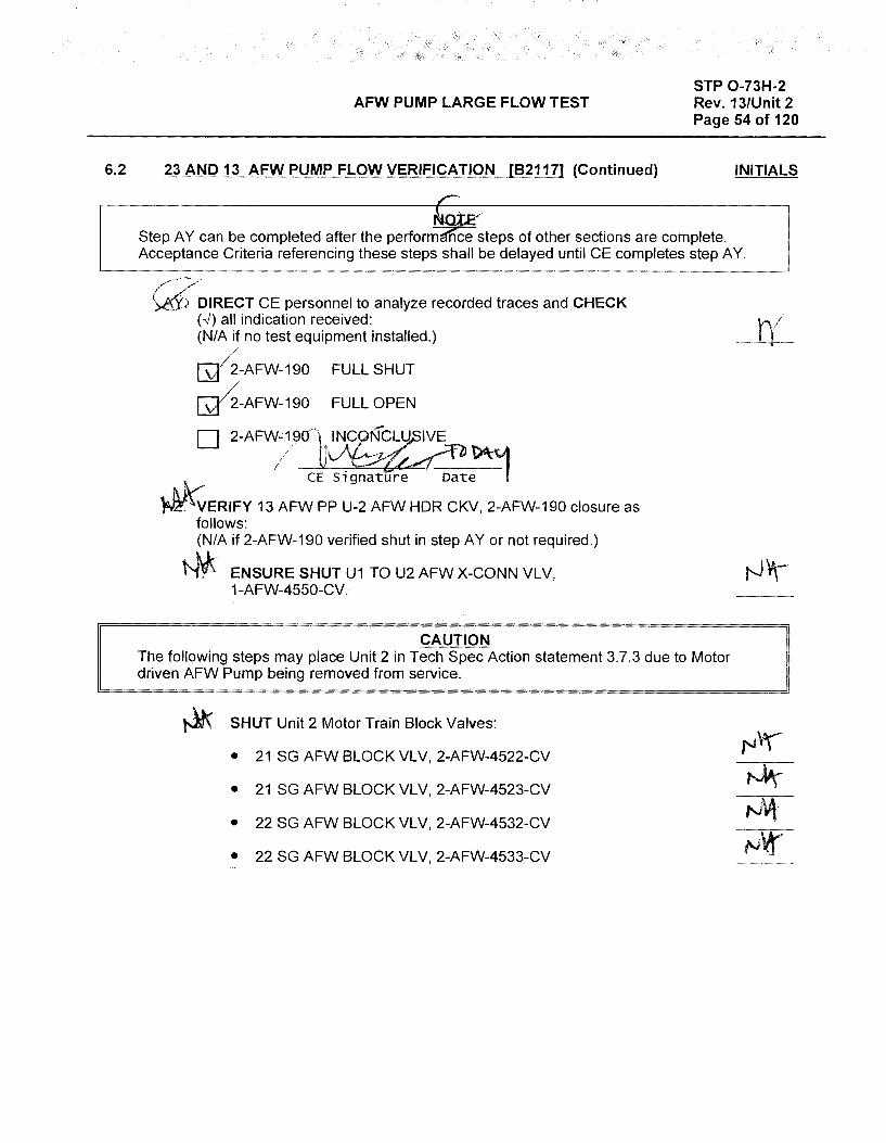
6.2
AFW PUMP LARGE FLOW TEST
23 AND 13 AFW PUMP FLOW VERIFICATION [82117] (Continued)
STP 0-73H-2 Rev. 13/Unit 2 Page 54 of 120
INITIALS
Step A Y can be completed after the perform ce steps of other sections are complete. Acceptance Criteria referencing these steps shall be delayed until CE completes step AY.
/-/ w) DIRECT CE personnel to analyze recorded traces and CHECK (.,_/) all indication received: (NIA if no test equipment installed.)
~-AFW-190 FULL SHUT
~-AFW-190 FULL OPEN
D 2-AFWc191~
CE signature oat~
~ERIFY 13 AFW PP U-2 AFW HOR CKV, 2-AFW-190 closure as follows: (NIA if 2-AFW-190 verified shut in step AY or not required.)
~ ENSURE SHUT U1 TO U2 AFW X-CONN VLV, 1-AFW-4550-CV.
CAUTION The following steps may place Unit 2 in Tech Spec Action statement 3.7.3 due to Motor driven AFW Pump being removed from service.
~ SHUT Unit 2 Motor Train Block Valves:
• 21 SG AFW BLOCK VLV, 2-AFW-4522-CV
• 21 SG AFW BLOCK VLV, 2-AFW-4523-CV
• 22 SG AFW BLOCK VLV, 2-AFW-4532-CV
• 22 SG AFW BLOCK VLV, 2-AFW-4533-CV
r{
Examinee:
Calvert Cliffs Nuclear Power Plant
2018 NRC Initial Licensed Operator Exam
JPM-SRO Admin4

Appendix C Job Performance Measure Worksheet Form ES-C-1
Facility: Calvert Cliffs 1 & 2
Alternate Path: No
Task Number: 093.080
JPM Number: SRO Admin4
Task Title: Startup Steam Generator Slowdown to the Condenser/Gire Water
Task Standard:
This JPM is complete when a SG Slowdown Liquid Radioactive Waste Continuous Release Permit is reviewed, conditions are evaluated for continued release, and ODCM actions are identified if RMS and Flow Instruments are taken OOS.
KIA Reference: 2.3.6 (2.0/3.8)
Method of Testing: Actual Performance-Classroom
Validation Time: 17 minutes
References and Tools Required:
1. CP-0601 Attachment (3), Steam Generator Slowdown Liquid Radioactive Waste Release Permit
2. ODCM Part 3.0/4.0.
3. 01-35, Radiation Monitoring System, Section 6.10 and Table 1.
SRO Admin4 Page 2 of 11

Appendix C Job Performance Measure Worksheet Form ES-C-1
JPM Setup Instructions:
1. CP-0601 Attachment (3), Steam Generator Slowdown Liquid Radioactive Waste Release Permit completed with following values
• Unit: 1
• Permit Number: L-20180401-1002-C
• Pre-Release Gamma Scan Number: 5Aug18 200002
• Release Source Volume: 3.679E+07 Liters
• Discharge Point: Unit-2 Checked
• Minimum Number Circulating Water Pumps Required: 5
• Dilution Flow Rate Pre-Release: 1.000E+06
• Maximum Release Flow Rate: 225
• 1 (2)-RE-4014 Background: 8.300E+01
• 1 (2)-RE-4095 Background: 1.800E+02
• Expected Response 1 (2)-RE-4014: 8.300E+01
• Expected Response 1 (2)-RE-4095: 1.800E+02
• Adjustable/Max Setpoint 1 (2)-RE-4014: 2.075E+02
• Adjustable/Max Setpoint 1 (2)-RE-4095: 4.500E+02
• Signatures for Independent Verification for Calculations, Prepared By, and SCO Approval with date of 8/5/18.
SRO Admin4 Page 3 of 11
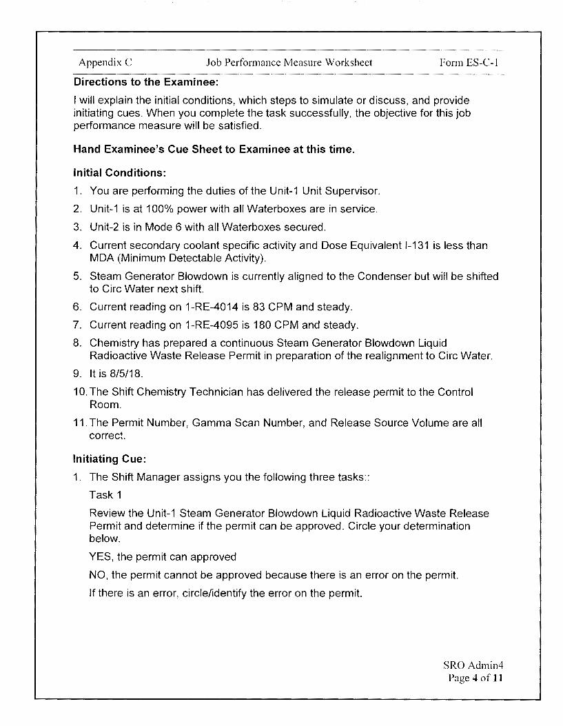
Appendix C Job Performance Measure Worksheet Form ES-C-1
Directions to the Examinee:
I will explain the initial conditions, which steps to simulate or discuss, and provide initiating cues. When you complete the task successfully, the objective for this job performance measure will be satisfied.
Hand Examinee's Cue Sheet to Examinee at this time.
Initial Conditions:
1. You are performing the duties of the Unit-1 Unit Supervisor.
2. Unit-1 is at 100% power with all Waterboxes are in service.
3. Unit-2 is in Mode 6 with all Waterboxes secured.
4. Current secondary coolant specific activity and Dose Equivalent 1-131 is less than MDA (Minimum Detectable Activity).
5. Steam Generator Slowdown is currently aligned to the Condenser but will be shifted to Gire Water next shift.
6. Current reading on 1-RE-4014 is 83 CPM and steady.
7. Current reading on 1-RE-4095 is 180 CPM and steady.
8. Chemistry has prepared a continuous Steam Generator Slowdown Liquid Radioactive Waste Release Permit in preparation of the realignment to Gire Water.
9. It is 8/5/18.
10. The Shift Chemistry Technician has delivered the release permit to the Control Room.
11. The Permit Number, Gamma Scan Number, and Release Source Volume are all correct.
Initiating Cue:
1. The Shift Manager assigns you the following three tasks::
Task 1
Review the Unit-1 Steam Generator Slowdown Liquid Radioactive Waste Release Permit and determine if the permit can be approved. Circle your determination below.
YES, the permit can approved
NO, the permit cannot be approved because there is an error on the permit.
If there is an error, circle/identify the error on the permit.
SRO Admin4 Page 4 of 11

Appendix C Job Performance Measure Worksheet Form ES-C-1
Task 2
Maintenance planned on 8/6/18, will remove both 1-RE-4014 and 1-RE-4095 from service, but power will be maintained to both RMS during the maintenance. In addition to a permit change, determine if Steam Generator blowdown to Circ Water can continue with both 1-RE-4014 and 1-RE-4095 OOS. Circle your determination below.
YES, blowdown can continue during the maintenance on both RMSs
NO, blowdown will have to be secured during the maintenance
If YES, document any required actions per the ODCM below.
Task 3
Maintenance planned on 8/13/18, will remove 1-Fl-4089, Steam Generator Slowdown Flow, from service. Determine if Steam Generator blowdown to Circ Water can continue with 1-Fl-4089 OOS. Circle your determination below.
YES, blowdown can continue during the maintenance on 1-Fl-4089
NO, blowdown will have to be secured during the maintenance
If YES, document any required actions per the ODCM below.
2. Are there any questions? You may begin.
SRO Admin4 Page 5 of 11
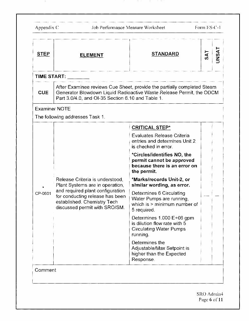
Appendix C Job Performance Measure Worksheet Form ES-C-1
I-
STEP STANDARD I- <C ELEMENT <C en
en z ::J
TIME START:
After Examinee reviews Cue Sheet, provide the partially completed Steam CUE Generator Slowdown Liquid Radioactive Waste Release Permit, the ODCM
Part 3.0/4.0, and 01-35 Section 6.10 and Table 1.
Examiner NOTE
The following addresses Task 1.
Release Criteria is understood,
* Plant Systems are in operation,
CP-0601 and required plant configuration
. for conducting release has been '! established. Chemistry Tech · discussed permit with SRO/SM.
Comment
CRITICAL STEP*
Evaluates Release Criteria entries and determines Unit 2 is checked in error.
*Circles/identifies NO, the permit cannot be approved because there is an error on the permit.
*Marks/records Unit-2, or similar wording, as error.
Determines 6 Circulating - -Water Pumps are running, which is > minimum number of 5 required.
Determines 1.000 E+06 gpm is dilution flow rate with 5 Circulating Water Pumps running.
Determines the Adjustable/Max Setpoint is higher than the Expected Response.
SRO Admin4 Page 6 of 11
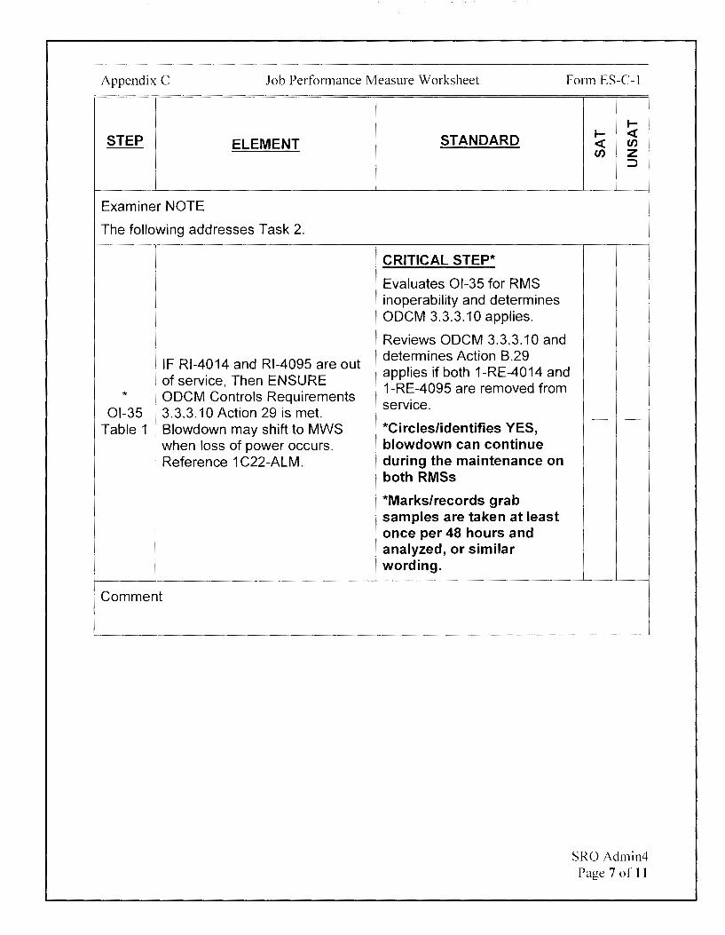
Appendix C Job Performance Measure Worksheet Form ES-C-1
STEP ELEMENT
Examiner NOTE
The following addresses Task 2.
IF Rl-4014 and Rl-4095 are out of service, Then ENSURE
* ODCM Controls Requirements 01-35 3.3.3.10 Action 29 is met.
Table 1 Blowdown may shift to MWS when loss of power occurs. Reference 1 C22-ALM.
'
Comment
STANDARD
CRITICAL STEP*
Evaluates 01-35 for RMS inoperability and determines ODCM 3.3.3.10 applies.
Reviews ODCM 3.3.3.10 and determines Action B.29 applies if both 1-RE-4014 and 1-RE-4095 are removed from service.
*Circles/identifies YES, blowdown can continue during the maintenance on both RMSs
*Marks/records grab samples are taken at least once per 48 hours and analyzed, or similar wording.
I-I- <( <( en en z
:J
- -
SRO Admin4 Page 7 of 11

Appendix C Job Performance Measure Worksheet Form ES-C-1
1--
STEP STANDARD 1-- <( ELEMENT <( en
en z ::::>
Examiner NOTE
The following addresses Task 3.
CRITICAL STEP*
Reviews ODCM 3.3.3.10 and determines Action 8.30
IF Fl-4089 is out of service, applies if 1-Fl-4089 is Then ENSURE ODCM Controls removed from service.
* 01-35
Requirements 3.3.3.10 Action *Circles/identifies YES, 30 is met. blowdown can continue - -
Table 1 During release, ESTIMATE flow during the maintenance on rate every four hours. 1-Fl-4089
*Marks/records flow rate is estimated at least once per 4 hours, or similar wording.
Comment
TERMINATING CUE:
This JPM is complete when a SG Slowdown Liquid Radioactive Waste Continuous Release Permit is reviewed, conditions are evaluated for continued release, and ODCM actions are identified if RMS and Flow Instruments are taken OOS.
The Examinee is expected to end the JPM.
TIME STOP:
SRO Admin4 Page 8 ofl 1

Appendix C Job Performance Measure Worksheet
Verification of Completion
Job Performance Measure Number: SRO Admin4
Examinee:
NRC Examiner:
Date Performed:
Facility Evaluator: ________________ _
Number of Attempts: ----------------Time to Complete: -----------------Follow up Question(s):
Examinee Response:
Result: SATISFACTORY UNSATISFACTORY -- --
Examiner's Signature and Date:
Form ES-C-1
SRO Admin4 Page 9 of 11

Appendix C
Initial Conditions:
Job Performance Measure Worksheet
EXAMINEE'S CUE SHEET
1. You are performing the duties of the Unit-1 Unit Supervisor.
2. Unit-1 is at 100% power with all Waterboxes are in service.
3. Unit-2 is in Mode 6 with all Waterboxes secured.
Form ES-C-1
4. Current secondary coolant specific activity and Dose Equivalent 1-131 is less than MDA (Minimum Detectable Activity).
5. Steam Generator Slowdown is currently aligned to the Condenser but will be shifted to Circ Water next shift.
6. Current reading on 1-RE-4014 is 83 CPM and steady.
7. Current reading on 1-RE-4095 is 180 CPM and steady.
8. Chemistry has prepared a continuous Steam Generator Slowdown Liquid Radioactive Waste Release Permit in preparation of the realignment to Circ Water.
9. It is 8/5/18.
10. The Shift Chemistry Technician has delivered the release permit to the Control Room.
11. The Permit Number, Gamma Scan Number, and Release Source Volume are all correct.
Initiating Cue:
1. The Shift Manager assigns you the following three tasks::
Task 1
Review the Unit-1 Steam Generator Slowdown Liquid Radioactive Waste Release Permit and determine if the permit can be approved. Circle your determination below.
YES, the permit can approved
NO, the permit cannot be approved because there is an error on the permit.
If there is an error, circle/identify the error on the permit.
Continued on next page
SRO Admin4 Page 10 of 11

Appendix C
Task 2
Job Performance Measure Worksheet
Form ES-C-1
Maintenance planned on 8/6/18, will remove both 1-RE-4014 and 1-RE-4095 from service, but power will be maintained to both RMS during the maintenance. In addition to a permit change, determine if Steam Generator blowdown to Circ Water can continue with both 1-RE-4014 and 1-RE-4095 OOS. Circle your determination below.
YES, blowdown can continue during the maintenance on both RMSs
NO, blowdown will have to be secured during the maintenance
If YES, document any required actions per the ODCM below.
Task 3
Maintenance planned on 8/13/18, will remove 1-Fl-4089, Steam Generator Blowdown Flow, from service. Determine if Steam Generator blowdown to Circ Water can continue with 1-Fl-4089 OOS. Circle your determination below.
YES, blowdown can continue during the maintenance on 1-Fl-4089
NO, blowdown will have to be secured during the maintenance
If YES, document any required actions per the ODCM below.
SRO Admin4 Page 11 of 11

OPENEMS LIQUID RADIOACTIVE WASTE RELEASE PERMITS CP-0601 Revision 02100
Page 50 of 57
Page 1 of 1 Attachment 3, Unit _i _ Steam Generator Slowdown Liquid Radioactive Waste Release Permit
Permit Number: L- 20 \{ 0 Y-'D l - l Ou 2 -- C/
Pre-Release Gamma Scan Number: '5AVt> \[ 200 062,.
Release Source Volume: "'.?.. {p"l9 E + n_, . ~ I L/1f't.S
RELEASE CRITERIA i~ ~ Discharge Point: D Unit 1j .@'Unit 2 } I Minimum Number Circulating Water Pumps Required: 5 Dilution Flow Rate Pre-Rele~e: l~O l;-+-O(o gpm Maximum Release Flow Rate: 225 gpm
1(2)-RE-4014 Background: i--:; 0 () £:- -r O ! cpm 1 (2)-RE-4095 Background: I, goo -e-+01.. cpm
Expected Response 1 (2)-RE-4014: 1, '?)o o £: 1 o I cpm Expected Response 1 (2)-RE-4095: l1 ~ 00 t:: T () t,. cpm
Adjustable/Max Setpoint 1(2)-RE-4014: '2 .D7 .>€"IO). cpm "--
Adjustable/Max Setpoint 1 (2)-RE-4095: +, S-o O t: t-o 2,.cpm
Independent Verification for Calculations: ,:-;ft-;71 , '~ V V u
Approval (Release Criteria is within ODCM Requirements)
Prepared By: Av<;.11 t-1 S /v\ I T1-i 00c) Print Name Time
SCO Approval: ro Ht-A '"1es t1' 1020
Release Criteria is understood, Plant Systems are in operation, and required plant configuration for conducting release has been established. Chemistry Tech discussed permit with SRO/SM.
SM/CRS: Print Name Si nature Date Time
RMS Pre-Op checks have been completed and release criteria reviewed. Correct setpoints entered in computer and Peer Checked. Flow Rate Meter Channel Check Satisfactory.
CRO: Print Name
Independent Verification of Alarm Setpoints.
CRO: Print Name
Release Data
Release Start Date:
Release End Date:
Number Circulating Water Pumps Operating During Release:
Post-Release Data and Review
Post-Release Gamma Scan Number:
Post-Release Volume:
Independent Verification for Calculations:
Permit Closed Out:
SCO Approval: (Required)
Print Name
Si nature Date
Si nature Date
Release Start Time:
Release End Date:
I Number Saltwater Pumps Operating During Release:
Date
Si nature Date
Time
Time
gpm
nme
Time

Appendix C
Initial Conditions:
Job Performance Measure Worksheet
EXAMINEE'S CUE SHEET
1. You are performing the duties of the Unit-1 Unit Supervisor.
2. Unit-1 is at 100% power with all Waterboxes are in service.
3. Unit-2 is in Mode 6 with all Waterboxes secured.
Form ES-C-1
4. Current secondary coolant specific activity and Dose Equivalent 1-131 is less than MDA (Minimum Detectable Activity).
5. Steam Generator Blowdown is currently aligned to the Condenser but will be shifted to Circ Water next shift.
6. Current reading on 1-RE-4014 is 83 CPM and steady.
7. Current reading on 1-RE-4095 is 180 CPM and steady.
8. Chemistry has prepared a continuous Steam Generator Blowdown Liquid Radioactive Waste Release Permit in preparation of the realignment to Circ Water.
9. It is 8/5/18.
10. The Shift Chemistry Technician has delivered the release permit to the Control Room.
11. The Permit Number, Gamma Scan Number, and Release Source Volume are all correct.
Initiating Cue:
1. The Shift Manager assigns you the following three tasks::
Task 1
Review the Unit-1 Steam Generator Blowdown Liquid Radioactive Waste Release Permit and determine if the permit can be approved. Circle your determination below.
permit cannot be approved because there is an error on the permit.
ere is an error, circle/identify the error on the permit.
Continued on next page
SRO Admin4 Page 10 of 11

Appendix C
Task 2
Job Performance Measure Worksheet
Form ES-C-1
Maintenance planned on 8/6/18, will remove both 1-RE-4014 and 1-RE-4095 from service, but power will be maintained to both RMS during the maintenance. In addition to a permit change, determine if Steam Generator blowdown to Circ Water can continue with both 1-RE-4014 and 1-RE-4095
~ircle your determination below.
~owdown can continue during the maintenance on both RMSs
NO, blowdown will have to be secured during the maintenance
If YES, document any required actions per the ODCM below.
G 12A-e, s A-M , ~ Tldc.&J A-r" Lt-~, ev e-rz, ~ ~<:. Pr,.lt> ~lrt.-'f ~f;o *
Task 3
Maintenance planned on 8/13/18, will remove 1-Fl-4089, Steam Generator Blowdown Flow, from service. Determine if Steam Generator blowdown to Circ Water can continue with 1-Fl-4089 OOS. Circle your determination
e. blowdown can continue during the maintenance on 1-Fl-4089
, blowdown will have to be secured during the maintenance
If YES, document any required actions per the ODCM below.
f- U>v.J ~ 15 ~ Tl t'VtTc1) /'rT (£-t'r=;., 0 N <K
r~ +. ttovtz,S ,t(
SRO Admin4 Page 11 of 11
Examinee:
Calvert Cliffs Nuclear Power Plant
2018 NRC Initial Licensed Operator Exam
JPM-SRO Admin5

Appendix C Job Performance Measure Worksheet Form ES-C-1
Facility: Calvert Cliffs 1 & 2
Alternate Path: No
JPM Number: SRO Admin5
Task Number: 204.025
Task Title: Determine whether a Reportable Occurrence has occurred
Task Standard:
This JPM is complete when seismic event data is evaluated to determine a Unit shutdown is required and the Operations Decision Tree #1 evaluated and Safety (SAF) Reportability events identified.
KIA Reference: 2.4.29 (3.1/4.4)
Method of Testing: Actual Performance-Classroom
Validation Time: 30 minutes
References and Tools Required:
1. 01-46, Seismic Measurement Equipment
2. ERPIP-3.0, Immediate Actions, Attachment (14), Seismic Event
3. Seismic Event Report Page 1
4. LS-AA-1020, Reportability Tables and Decision Trees
5. LS-AA-1010 Safety (SAF) Reportable Events
JPM Setup Instructions:
1. 01-46 placekeeping marks completed up to Step 6.3.B.2.
2. ERPIP-3.0 Attachment (14) placekeeping marks completed with the following information:
• Implementation Time: 1200
• Implementation Date: 8/5/18
• Steps 1.0, 1.1, and 1.2 marked as completed
3. Seismic Event Report Page 1 created with data per the attached.
4. Blank Operations Decision Tree #1 with LS-AA-1020 Pages 95-98.
SRO Admin5 Page 2 of 13

Appendix C Job Performance Measure Worksheet Form ES-C-1
KMI Condor Event Summary
Automatic Processing Date: 08/05/2018 12:00:00 (Local)
Date Time Abs Max Peaks (g) Recorder
Event
Run
Time Ch. 1 Ch.2 Ch.3
(ROOl) R001_BQ003.EVT OYEOOl
08/05/2018 11:57:00 01:81 0.0801 0.0531 0.0811
(R002) R002_BM003.EVT OYE002
08/05/2018 11:57:00 01:81 0.0801 0.0531 0.0811
(R003) R003_BH003.EVT OYE003
08/05/2018 11:57:00 01:81 0.0801 0.0531 0.0811
(R004) R004_BJ003.EVT OYE004
08/05/2018 11:57:00 01:81 0.0802 0.0532 0.0831
(ROOS) ROOS_BF003.EVT OYE005
08/05/2018 11:57:00 01:81 0.1410 0.0950 0.0131
Footnotes: When assembling output, be sure to use event time as your collating
basis because Recorder/Event numbers may not be concurrent.
Copies of record/Event files for this event, if generated, will be found in the
C:\AssociatedEvents\20131219_152106\directory, with file extension .EVT.
OBE
Exc'd
YES
YES
YES
YES
YES
SRO Admin5 Page 3 of 13
Appendix C Job Performance Measure Worksheet Form ES-C-1
Directions to the Examinee:
I will explain the initial conditions, which steps to simulate or discuss, and provide initiating cues. When you complete the task successfully, the objective for this job performance measure will be satisfied.
Hand Examinee's Cue Sheet to Examinee at this time.
Initial Conditions:
1. You are performing the duties of the Unit-2 Unit Supervisor.
2. Both Units were initially at 100% power.
3. Annunciator SEISMIC EVENT alarms on 1 C26.
4. An earthquake is felt by personnel on site.
5. Unit-1 automatically tripped due to a loose wire in the Main Generator Exciter ground circuit.
6. Unit-2 remained at 100%
7. EOP-1 was implemented on Unit-1.
8. The Shift Manager has implemented ERPIP-3.0 Attachment 14 for a Seismic Event.
9. Page 1 of the Seismic Event Report has been obtained per 01-46.
10. The Shift Manager has declared an Alert and is in the process of completing the Initial Notification Form.
Initiating Cue:
1. The Shift Manager has assigned you two tasks while he is completing and initiating the communication of the Initial Notification Form:
Task 1
Evaluate ERPIP-3.0 Attachment 14 and determine if a Unit-2 Shutdown is required. Circle your determination below.
YES, Unit-2 must be shutdown
NO, Unit-2 can remain at 100% power.
If YES, document the reason below:
SRO Admin5 Page 4 of 13

Appendix C
Task 2
Job Performance Measure Worksheet Form ES-C-1
Determine if a Reportable Event has occurred per Operations Decision Tree #1 in LS-AA-1020. Evaluate only the Safety (SAF) Reportability Events for both units using the Operations Decision Tree #1. Operations Decision Trees #2-4, the Radiological (RAD), Security (SEC), and Environmental (ENV) Reportability Events will all be evaluated by the Shift Manager after the Initial Notification Form is communicated.
Document the Safety (SAF) evaluation by using LS-AA-1020 Operations Decision Tree #1. Circle all Yes/No answers and circle all applicable SAF Reportability Events on the Operations Decision Tree. SAF 3.2 and 3.3 do not apply to Calvert Cliffs.
The following information is known:
• The plant is not in an unanalyzed condition based on the Seismic Event Report data
• All systems are responding as expected
• A walkdown by the Equipment Operators has determined no system degradation
• All communications systems are available
• The grid is stable
2. Are there any questions? You may begin.
SRO Admin5 Page 5 of 13

Appendix C Job Performance Measure Worksheet Form ES-C-1
I-
STEP STANDARD I- < ELEMENT < U) U) z
::>
TIME START:
After Examinee reviews Cue Sheet, provide partially completed 01-46,
CUE Seismic Event Report Page 1, partially completed ERPIP-3.0 Attachment 14, LS-AA-1020, LS-AA-1110, and a blank Operations Decision Tree #1 from LS-AA-1020.
Examiner NOTE
The following addresses Task 1.
Determines ERPIP-3.0
Task 1 Determine if a Unit-2 shutdown Attachment 14 guidance must is required. be evaluated to determine if - -
Unit-2 shutdown is required.
Comment
Evaluates Seismic Event If peak acceleration values are Report data.
I greater than: Determines max Horizontal
0.15g Horizontal OR 0.10 g reading from Ch.1 is 0.141 . 3.0 . Vertical (Design Basis
Att 14 1 Earthquake), THEN: Determines max Vertical reading from Ch. 2 is 0.0950. - -
2.0 2.1 COMMENCE a controlled shutdown PER OP-3, AND Determines step is NIA since
PLACE both Units in Mode 5 as max Horizontal reading is <
expeditiously as possible. 0.15g and max Vertical reading is < 0.1 Og.
Comment
SRO Admin5 Page 6 of 13
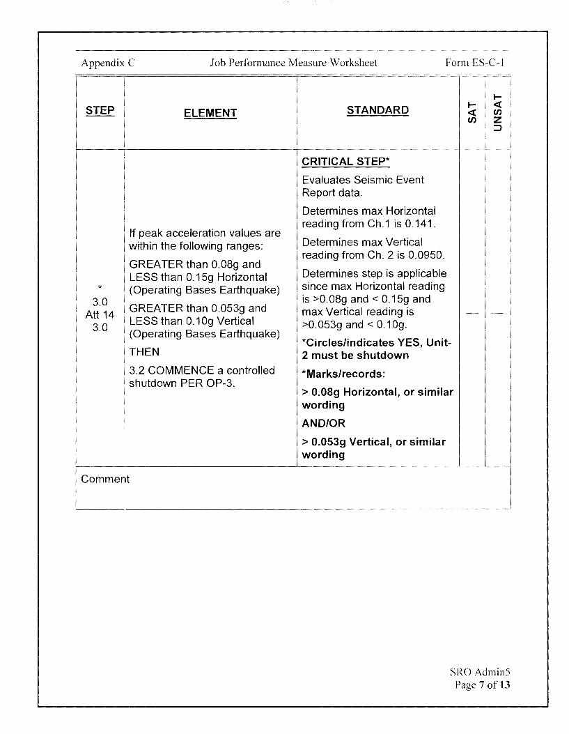
Appendix C Job Performance Measure Worksheet Form ES-C-1
STEP ELEMENT
If peak acceleration values are within the following ranges:
GREATER than 0.08g and LESS than 0.15g Horizontal
* (Operating Bases Earthquake) 3.0 GREATER than 0.053g and
Att 14 3.0
LESS than 0.1 Og Vertical (Operating Bases Earthquake)
THEN
3.2 COMMENCE a controlled shutdown PER OP-3.
Comment
I-
STANDARD I- <( <( en en z
:J
CRITICAL STEP*
Evaluates Seismic Event Report data.
Determines max Horizontal reading from Ch.1 is 0.141.
Determines max Vertical reading from Ch. 2 is 0.0950.
Determines step is applicable since max Horizontal reading is >0.08g and < 0.15g and max Vertical reading is - ->0.053g and< 0.10g.
*Circles/indicates YES, Unit-2 must be shutdown
*Marks/records:
> 0.08g Horizontal, or similar wording
AND/OR
> 0.053g Vertical, or similar wording
SRO Admin5 Page 7 of 13

Appendix C Job Performance Measure Worksheet Form ES-C-1
I-
STEP STANDARD I- <( ELEMENT <( en
en z :::>
Examiner NOTE
The following addresses Task 2.
Determines LS-AA-1020 and LS-AA-1110 must be
Determine Safety (SAF) evaluated to determine what
Task 2 Reportability Events per LS-AA- Safety related Reportability 1020 using Operations Decision Events apply. - -
Tree Proceeds to LS-AA-1020 Operations Decision Tree #1.
Comment
Examiner NOTE
Examinee may also select SAF 1.12 when evaluating the Operations Decision Tree if earthquake is interpreted as posing an actual threat to the safety of the plant.
! I
*
1020 Emergency Plan Activated
Tree #1
Comment
CRITICAL STEP*
Determines Emergency Plan activated based on Cue Sheet.
*Circles YES for Decision Diamond.
Evaluates SAF 1.1, 1.2, 1.3, 1.4, 1.5, 1.7, 1.8, 1.10, 1.12, 1.13, and 1.16 against event using LS-AA-1110.
Determines SAF 1.1 applies.
*Circles/indicates SAF 1.1 Reportable Events on the Operations Decision Tree #1.
- -
SRO Admin5 Page 8 of 13
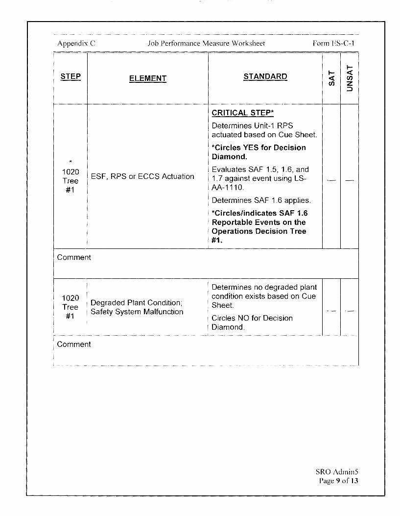
Appendix C Job Performance Measure Worksheet Form ES-C-1
STEP ELEMENT
* 1020 Tree
ESF, RPS or ECCS Actuation
#1
Comment
1020 Tree
Degraded Plant Condition;
1
Safety System Malfunction #1
Comment
I-
STANDARD I- <( <( en en z
:)
CRITICAL STEP*
Determines Unit-1 RPS actuated based on Cue Sheet.
*Circles YES for Decision Diamond.
Evaluates SAF 1.5, 1.6, and 1. 7 against event using LS- - -AA-1110.
Determines SAF 1.6 applies.
*Circles/indicates SAF 1.6 Reportable Events on the Operations Decision Tree #1.
Determines no degraded plant condition exists based on Cue Sheet.
Circles NO for Decision Diamond.
- -
SRO Admin5 Page 9 of 13
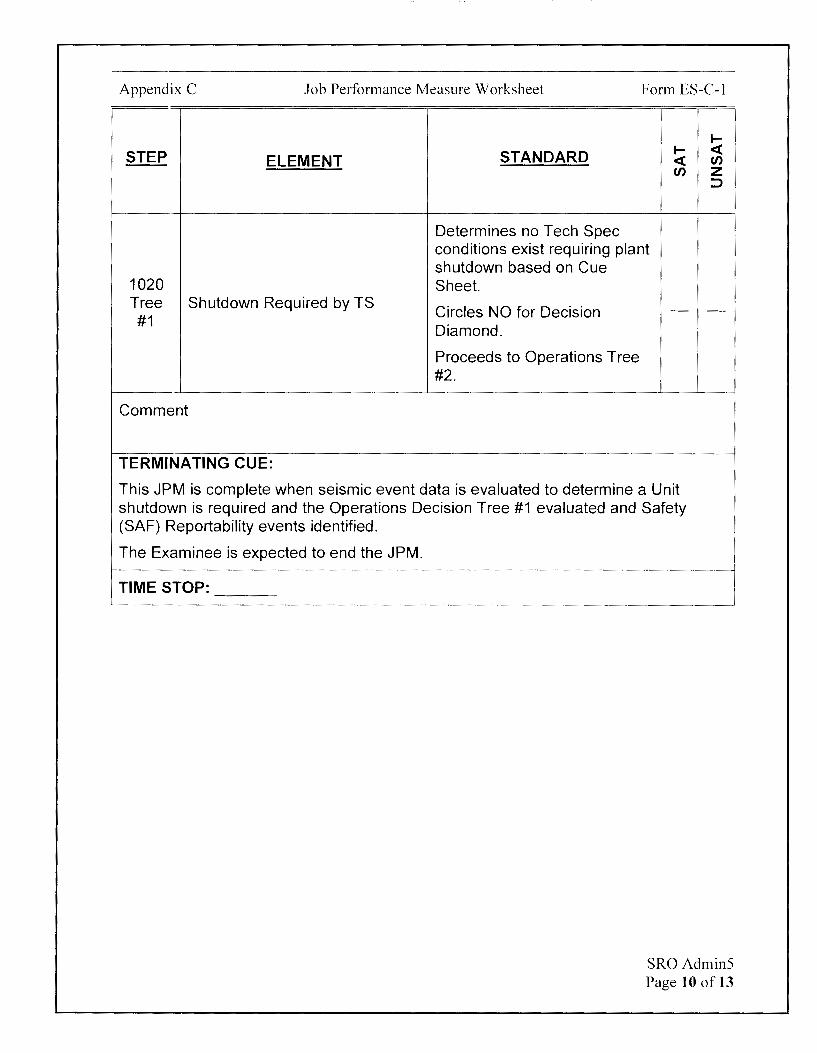
Appendix C Job Performance Measure Worksheet Form ES-C-1
I-
STEP STANDARD I- <( ELEMENT <( Cl)
Cl) z :::>
Determines no Tech Spec conditions exist requiring plant shutdown based on Cue
1020 Sheet. Tree Shutdown Required by TS
Circles NO for Decision - -#1
Diamond.
Proceeds to Operations Tree #2.
Comment
TERMINATING CUE:
This JPM is complete when seismic event data is evaluated to determine a Unit shutdown is required and the Operations Decision Tree #1 evaluated and Safety (SAF) Reportability events identified.
The Examinee is expected to end the JPM.
TIME STOP:
SR0Admin5 Page 10 of 13

Appendix C Job Performance Measure Worksheet
Verification of Completion
Job Performance Measure Number: SRO Admin5
Examinee:
NRC Examiner:
Date Performed:
Facility Evaluator: ________________ _
Number of Attempts: _______________ _
Time to Complete: ________________ _
Follow up Question(s):
Examinee Response:
Result: SATISFACTORY UNSATISFACTORY -- --
Examiner's Signature and Date:
Form ES-C-1
SRO Admin5 Page 11 of 13
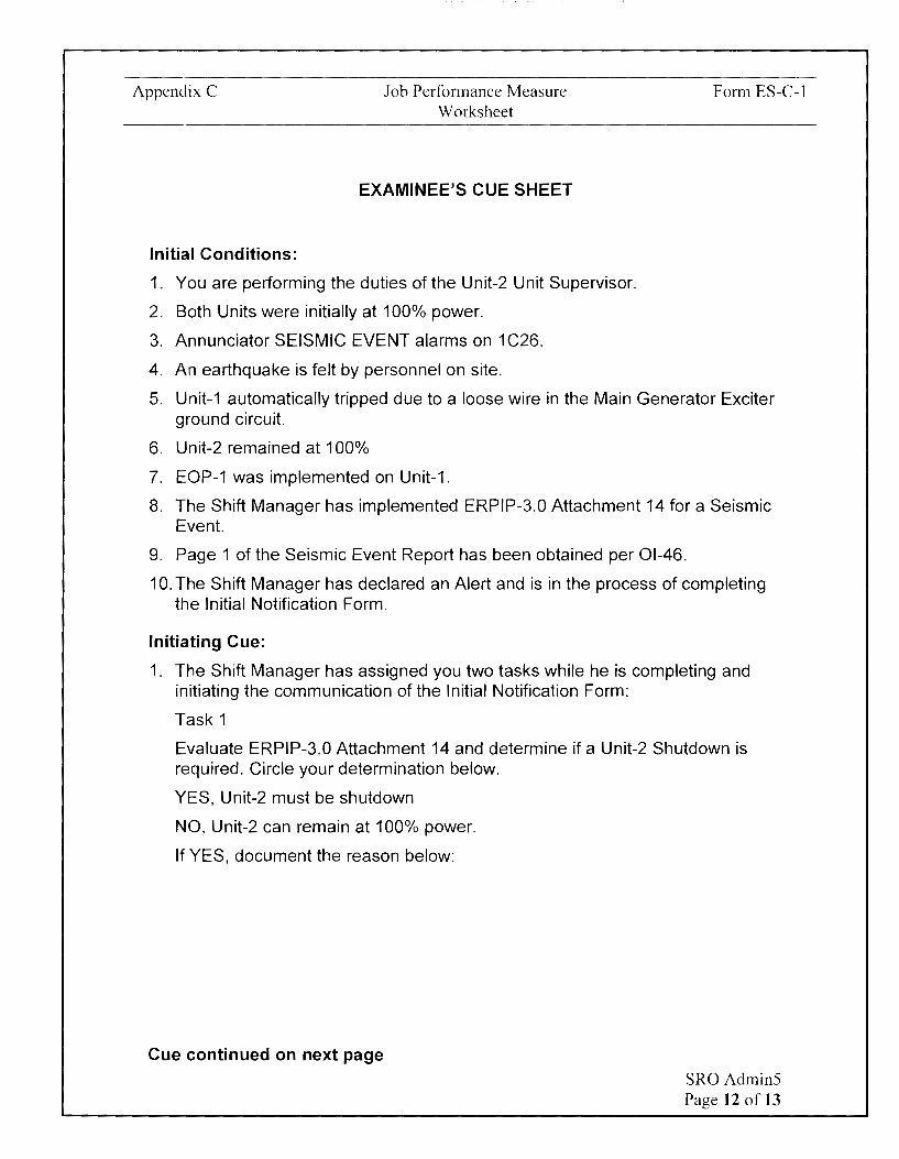
Appendix C
Initial Conditions:
Job Performance Measure Worksheet
EXAMINEE'S CUE SHEET
1. You are performing the duties of the Unit-2 Unit Supervisor.
2. Both Units were initially at 100% power.
3. Annunciator SEISMIC EVENT alarms on 1 C26.
4. An earthquake is felt by personnel on site.
Form ES-C-1
5. Unit-1 automatically tripped due to a loose wire in the Main Generator Exciter ground circuit.
6. Unit-2 remained at 100%
7. EOP-1 was implemented on Unit-1.
8. The Shift Manager has implemented ERPIP-3.0 Attachment 14 for a Seismic Event.
9. Page 1 of the Seismic Event Report has been obtained per 01-46.
10. The Shift Manager has declared an Alert and is in the process of completing the Initial Notification Form.
Initiating Cue:
1. The Shift Manager has assigned you two tasks while he is completing and initiating the communication of the Initial Notification Form:
Task 1
Evaluate ERPIP-3.0 Attachment 14 and determine if a Unit-2 Shutdown is required. Circle your determination below.
YES, Unit-2 must be shutdown
NO, Unit-2 can remain at 100% power.
If YES, document the reason below:
Cue continued on next page SRO Admin5 Page 12 of 13

Appendix C
Task 2
Job Performance Measure Worksheet
Form ES-C-1
Determine if a Reportable Event has occurred per Operations Decision Tree # 1 in LS-AA-1020. Evaluate only the Safety (SAF) Reportability Events for both units using the Operations Decision Tree #1. Operations Decision Trees #2-4, the Radiological (RAD), Security (SEC), and Environmental (ENV) Reportability Events will all be evaluated by the Shift Manager after the Initial Notification Form is communicated.
Document the Safety (SAF) evaluation by using LS-AA-1020 Operations Decision Tree #1. Circle all Yes/No answers and circle all applicable SAF Reportability Events on the Operations Decision Tree. SAF 3.2 and 3.3 do not apply to Calvert Cliffs.
The following information is known:
• The plant is not in an unanalyzed condition based on the Seismic Event Report data
• All systems are responding as expected
• A walkdown by the Equipment Operators has determined no system degradation
• All communications systems are available
• The grid is stable
SR0Admin5 Page 13 of 13
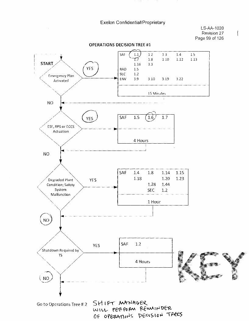
Exelon Confidential/Proprietary
OPERATIONS DECISION TREE #1
r----1 SAF 1.2 1.3
1.8 1.10
I STARY s 1.16 3.3
I ~ne,geocy Piao
RAD 1.5
SEC 1.2
~ Activated ENV 3.9 3.10 3.19
15 Minutes
NO ---~-~ --- --~-- --
0', RPS oc ECCS
~ Actuation
NO
Degraded Plant
Condition; Safety
System
Malfunction
Shutdown Required by
TS
Q
YES
YES
SAF 1.5 1.7
4 Hours
SAF 1.4 1.8 1.14 1.18 1.20
1.28 1.44
SEC 1.2
1 Hour
SAF 1.2
4 Hours
Go to Operations Tree# 2 SH I P"r"" J\A}n.JPa,Bl..._ W \ \;\...- f~ ft> fW ?--~ I rJ t)f;"ft
1.4
1.12
3.22
1.15 1.23
Of- OVE::tlA'flor.l~ \)6-«Slo~ '~
1.5
LS-AA-1020 Revision 27
Page 99 of 126
1.13

Appendix C
Initial Conditions:
Job Performance Measure Worksheet
EXAMINEE'S CUE SHEET
1. You are performing the duties of the Unit-2 Unit Supervisor.
2. Both Units were initially at 100% power.
3. Annunciator SEISMIC EVENT alarms on 1 C26.
4. An earthquake is felt by personnel on site.
Form ES-C-1
5. Unit-1 automatically tripped due to a loose wire in the Main Generator Exciter ground circuit.
6. Unit-2 remained at 100%
7. EOP-1 was implemented on Unit-1.
8. The Shift Manager has implemented ERPIP-3.0 Attachment 14 for a Seismic Event.
9. Page 1 of the Seismic Event Report has been obtained per 01-46.
10. The Shift Manager has declared an Alert and is in the process of completing the Initial Notification Form.
Initiating Cue:
1. The Shift Manager has assigned you two tasks while he is completing and initiating the communication of the Initial Notification Form:
Task 1
Evaluate ERPIP-3.0 Attachment 14 and determine if a Unit-2 Shutdown is ~d. Circle your determination below.
~nit-2 must be shutdown
NO, Unit-2 can remain at 100% power.
If YES, document the reason below:
7 0. o 8 '<I- in 11, 1 'tt> .. 11\"l- lt.><O / rn_ f o . o q 't If oZ-1 , e1n. ~
Cue continued on next page
SRO Admin5 Page 12 of 13
Calvert Cliffs Nuclear Power Plant
2018 NRC Initial Licensed Operator Exam
JPM-Simulator1

Appendix C Job Performance Measure Worksheet
Facility: Calvert Cliffs 1 & 2
Alternate Path: Yes
Task Number: 041.007
Task Title: Dilute the RCS via eves Task Standard:
Form ES-C-1
JPM Number: Simulator1
This JPM is complete when a 30 gallon DI is makeup to the VCT is completed, the unexpected loss of 1Y10 has been identified, and immediate actions are taken per AOP-7J-1 for a loss of 1Y10.
Time Critical Task: No
K/A Reference: 004A2.06 (4.2/4.3)
Method of Testing: Actual Performance-Simulator
Validation Time: 10 minutes
References and Tools Required:
1. 01-28. eves Boration, Dilution And Makeup Operations
2. Immediate Actions from 100% Power
3. AOP-71, Loss of 4KV, 480Volt, Or 208/120 Volt Instrument Bus Power
JPM Setup Instructions:
1. Reset to IC-34 (Both Units 100%, MOC).
2. Ensure 1-FQIS-21 OX on 1 CO? is set to O gallons (i.e. reads O while pushing red button)
3. Ensure 1-FQIS-21 OY on 1 CO? reading 0.
4. Malfunctions:
a. 120v002 02 on Event 1
Simulator I Page 2 of 13

Appendix C Job Performance Measure Worksheet Form ES-C-1
Directions to the Examinee:
I will explain the initial conditions, which steps to simulate or discuss, and provide initiating cues. When you complete the task successfully, the objective for this job performance measure will be satisfied.
Hand Examinee's Cue Sheet to Examinee at this time.
Initial Conditions:
1. You are performing the duties of the Unit-1 RO.
2. Unit-1 is at 100%.
3. A 30 gallon DI addition to the VCT is now required to maintain normal power level.
Initiating Cue:
1. You are to complete the 30 gallon dilution per Ol-2B, Step 6.18, Page 74.
2. Are there any questions? You may begin.
Simulator I Page 3 of 13
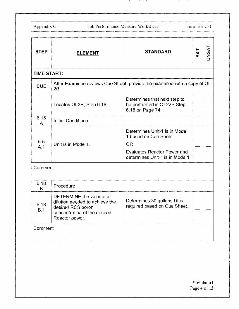
Appendix C Job Performance Measure Worksheet Form ES-C-1
I-
STEP STANDARD I- <( ELEMENT <( rn
rn z ::J
TIME START:
CUE After Examinee reviews Cue Sheet, provide the examinee with a copy of 01-28.
Locates 01-28, Step 6.18
6.18 Initial Conditions
A
6.5 Unit is in Mode 1.
A.1
Comment
6.18 1. Procedure
8
' DETERMINE the volume of
6.18 dilution needed to achieve the desired RCS boron
8.1 concentration of the desired Reactor power.
Comment
Determines that next step to be performed is 01-228 Step 6.18 on Page 74.
Determines Unit-1 is in Mode 1 based on Cue Sheet
OR
Evaluates Reactor Power and determines Unit-1 is in Mode 1
Determines 30 gallons DI is required based on Cue Sheet.
- -
- -
- -
Simulator I Page 4 of 13
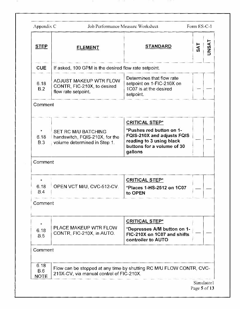
Appendix C Job Performance Measure Worksheet Form ES-C-1
I-
STEP STANDARD I- <( ELEMENT <( en
en z ::J
CUE If asked, 100 GPM is the desired flow rate setpoint.
ADJUST MAKEUP WTR FLOW Determines that flow rate
6.18 CONTR, FIC-21 OX, to desired
setpoint on 1-FIC-21 OX on 8.2 1 CO? is at the desired - -
flow rate setpoint. setpoint.
Comment
CRITICAL STEP*
* SET RC M/U BATCHING *Pushes red button on 1-
6.18 handswitch, FQIS-21 OX, for the FQIS-210X and adjusts FQIS
[ volume determined in Step 1. reading to 3 using black - -8.3
buttons for a volume of 30 gallons
Comment
* CRITICAL STEP* 6.18 OPEN VCT M/U, CVC-512-CV. *Places 1-HS-2512 on 1 C07 --8.4 to OPEN
Comment
CRITICAL STEP* *
6.18 PLACE MAKEUP WTR FLOW *Depresses AIM button on 1-CONTR, FIC-210X, in AUTO. FIC-21 OX on 1 C07 and shifts - -
8.5 controller to AUTO
Comment
6.18 Flow can be stopped at any time by shutting RC MIU FLOW CONTR, CVC-
8.6 NOTE
21 OX-CV, via manual control of FIC-21 OX.
Simulatorl Page 5 of 13

Appendix C Job Performance Measure Worksheet Form ES-C-1
I-
STEP STANDARD I- <( ELEMENT <( (J)
(J) z ::J
CRITICAL STEP*
WHEN CVC-21 OX-CV indicates Observes 1-RCS-21 OX-CV
* indication on 1 CO? 6.18
intermediate, THEN PLACE M/U MODE SEL SW, HS-210, in *After RCS-210X-CV - -
B.6 DILUTE. indicates intermediate or in
the open position, places 1-HS-210 on 1 C07 to DILUTE
Comment
Observes 1-FQIS-210X on 1 CO? and determines FQIS is
WHEN desired to secure dilution counting down. 6.18 OR the RC MIU BATCHING 8.7 handswitch, FQIS-210X counts After 1-FQIS-210X has - -
! down to zero, THEN: counted down to zero, i determines step is now
applicable.
Comment
Examiner NOTE
Examinee can perform 6.18.B.7 bulleted steps in any order.
* 6.18 CRITICAL STEP* 8.7
PLACE VCT M/U handswitch, *Places 1-HS-2512 on 1C07 HS-2512, to CLOSE. - -
1st to CLOSE Bullet
Comment
Simulator! Page 6 of 13

Appendix C Job Performance Measure Worksheet Form ES-C-1
1--
STEP STANDARD 1-- <( ELEMENT <( (J)
(J) z :::>
6.18 B.7 Due to circuit design the selected RCMU Pump may continue to run after 2nd taking M/U MODE SEL SW, HS-210 to MANUAL. The RCMU Pump can be
Bullet stopped by taking he selected pump handswitch to STOP. NOTE 6.18 B.7 PLACE M/U MODE SEL SW, Places 1-HS-210 on 1C07 to 2nd HS-210, to MANUAL MANUAL
Bullet
Comment
6.18 Depresses AIM button on 1-
PLACE MAKEUP WTR FLOW FIC-210X on 1C07 and shifts B.7
CONTR, FIC-210X, in MANUAL controller to MANUAL. 3rd
Bullet , with a 0% output signal. Lowers controller output of 1-I
i FIC-210X on 1C07 to 0%. I
Comment
Examiner NOTE
Direct Simulator Driver to insert Event 1. This will cause loss of 1Y10.
Alternate Path Starts Here
- -
- -
Simulator I Page 7 of 13

Appendix C Job Performance Measure Worksheet Form ES-C-1
I-
STEP STANDARD I- <( ELEMENT <( en
en z ::::>
After Examinee notes unexpected alarms:
Monitor the Primary. CUE Once the monitoring report is provided:
CRO reports RPS is not calling for a trip. Evaluate for a potential bus loss based on indications at 1 C05 only.
Notes unexpected alarms and announces multiple alarms.
Monitors the primary using Determines multiple unexpected monitoring plaque on 1 C05 alarms received and monitors and determines primary is not - -the Primary. stable based on PZR level
trends on 1 C06.
Reports to the Unit Supervisor
i
the Primary is not stable.
Comment
Evaluates indications at 1 C05 Determines that 1Y10 as a minimum is lost based on
for electrical power malfunction. - -indications at 1 C05.
After the Examinee has evaluated for and reported the potential bus loss based on 1 C05 indications:
CUE The STA will evaluate the Preliminary section of AOP-71-1. Perform the Immediate Actions for a loss of 1Y10. Hand Immediate Actions From 100% Power to Examinee.
Examiner NOTE
Examinee may first perform Charging Pump actions (41h bullet) before Opening MOV-501 and before evaluating Tcold for trends.
Simulator I Page 8 of 13

Appendix C Job Performance Measure Worksheet Form ES-C-1
1--
STEP STANDARD I- <( ELEMENT <( en
en z :J
Locates Immediate Actions Locates Immediate Actions From 100% Power steps for loss From 100% Power steps for - -of 1Y10. loss of 1Y10.
* IA CRITICAL STEP*
1Y10 Open VCT outlet CV-501. *Places 1-HS-2501 on 1 C07 - -1st to OPEN
Bullet
Comment
* I IA CRITICAL STEP*
1Y10 / Shut RWT to CHG CV-504. *Places 1-HS-2504 on 1 C07 - -2nd I to CLOSE
Bullet
Comment
Examiner NOTE
Examinee may first perform Charging Pump actions (41h bullet) while evaluating Tcold for trends.
Examinee must ensure Tcold is within 2°F of program and may choose to raise Tcold by lowering Turbine load once Tcold is< 2°F of program.
Simulator! Page 9 of 13

Appendix C Job Performance Measure Worksheet Form ES-C-1
I-
STEP STANDARD I- < ELEMENT < en
en z ::::>
CRITICAL STEP*
Monitors Tcold on either 1-TI-124 on 1C05 or 1-TI-112C/122C on 1 C06.
Determines if Tcold is within 2°F of program.
* *If Tc> 2°F off program, IA
Adjust Turbine to maintain Tc on lowers Turbine load by 1Y10 placing 1-CS-80 on 1C02 to program. - -3rd LOWER until Tcold is < 2°F
Bullet off program.
OR
*If Tc > 2°F off program, lowers Turbine load by selecting LOWER on MK6 Load Set Manual Adj until Tcold is < 2°F off program.
Comment
Examiner NOTE
Examinee may place all three Charging Pump handswitches in PULL TO LOCK based on PZR level.
Simulatorl Page 10 of 13
Appendix C Job Performance Measure Worksheet Form ES-C-1
I-
STEP STANDARD I- <( ELEMENT <( Cl)
Cl) z ::J
If Examinee recommends placing all three Charging Pumps in PULL TO LOCK:
CUE Place all three Charging Pumps in PULL TO LOCK.
If Examinee reports PZR level is > 225":
Ensure all three Charging Pumps in PULL TO LOCK.
CRITICAL STEP*
* *Places at least two of the
IA following three handswitches in PULL TO
1Y10 Place 2 Charging Pumps in PTL. LOCK: - -4th
Bullet • 1-HS-224X on 1 C07 • 1-HS-224Y on 1 C07 • 1-HS-2242 on 1 C07
i
Comment
TERMINATING CUE: This JPM is complete when a 30 gallon DI makeup to the VCT is completed, the unexpected loss of 1Y10 has been identified, and immediate actions are taken per AOP-7 J-1 for a loss of 1Y10.
The Examiner is expected to end the JPM.
TIME STOP:
Simulator! Page 11 of 13

Appendix C Job Performance Measure Worksheet
Verification of Completion
Job Performance Measure Number: Simulator1
Examinee:
NRC Examiner:
Date Performed:
Facility Evaluator: ________________ _
Number of Attempts: _______________ _
Time to Complete: -----------------
Follow up Question(s):
Examinee Response:
Result: SATISFACTORY UNSATISFACTORY -- --
Examiner's Signature and Date:
Form ES-C-1
Simulator I Page 12 of 13
Appendix C
Initial Conditions:
Job Performance Measure Worksheet
EXAMINEE'S CUE SHEET
1. You are performing the duties of the Unit-1 RO.
2. Unit-1 is at 100%.
Form ES-C-1
3. A 30 gallon DI addition to the VCT is now required to maintain normal power level.
Initiating Cue:
1. You are to complete the 30 gallon dilution per 01-28, Step 6.18, Page 74.
Simulator! Page 13 of 13
Calvert Cliffs Nuclear Power Plant
2018 NRC Initial Licensed Operator Exam
JPM-Simulator2

Appendix C Job Performance Measure Worksheet Form ES-C-1
Facility: Calvert Cliffs 1 & 2
Alternate Path: No
JPM Number: Simulator2
Task Number: 201.057
Task Title: Monitor ESFAS Actuation
Task Standard: This JPM is complete when SIAS has been reset.
K/A Reference: 013A4.02 (4.3/4.4)
Method of Testing: Actual Performance-Simulator
Validation Time: 13 minutes
References and Tools Required:
1. EOP-6, Steam Generator Tube Rupture
2. EOP-Attachments
JPM Setup Instructions:
1. Placekeep EOP-Attachment (2) SIAS Verification Checklist with steps 1C08/1C09/1C10 a-i, all 1C13, all 1C18A/1C18B, all 1C34, all 1C90, and all 1C101 steps marked as complete.
2. Annotate on EOP-Attachment (2) SIAS Verification Checklist steps 1 C08/1C09/1C10 a-b that HSPI and LPSI are in PTL for HPSI Throttling.
3. Reset to IC-34.
4. Ensure keys are inserted in 1-HS-5 and 1-HS-6 on 1C10.
5. Place 1-HS-5464 in OPEN on 1C10.
6. Insert Override P1 CO? F07 L TON to Off. - -
7. Insert a 10 GPM SG tube leak on 11 SG using malfunction ms001_01.
8. Once Condenser Off-Gas RMS alarms, manually trip the Reactor.
9. Initiate SIAS manually by depressing 1-HS-1 on 1C09 and 1-HS-2 on 1C10.
10. Perform the following EOP-0 actions:
• Manually trip 11A and 128 RCPs on 1 C06.
• Start 13 AFW Pump at 1 C03.
• Trip both 11 and 12 SGFPs at 1 C03.
• Place 1-HS-4011 and 1-HS-4013 in CLOSE on 1C03.
• Place 1-HS-4516 and 1-HS-4517 in CLOSE on 1C03.
• Place 1-HS-2515 and 1-HS-2516 in CLOSE on 1C07.
Simulator2 Page 2 of 13

Appendix C Job Performance Measure Worksheet Form ES-C-1
11. Commence a cooldown/depressurization to establish the following conditions:
• RCS pressure < 1500 PSIA
• RCS temperature < 500°F
• Lower cooldown rate once < 500°F
• Plant cooldown in progress with limited Annunciators coming in alarm
12. While cooling down, perform the following EOP-6 actions:
• Place 1-HS-2501 in CLOSE on 1 C07
• Place 1-HS-2504 in CLOSE on 1 C07
• Block SGIS
• Isolate 11 SG per EOP-6
• Establish 11 SG between (-) 10 and O"
• PZR level > 120"
• Place 11/13 HPSI Pumps in PULL TO LOCK
• Place 11/12 LPSI Pumps in PULL TO LOCK
• Place 11/12/13 Condensate Booster Pumps in PULL TO LOCK
• Place 13 Condensate Pump in PULL TO LOCK
• Place 11/12 Heater Drain Pumps in PULL TO LOCK
• Place all PZR heaters in OFF on 1 C06
13. Match the following handswitch flags to running conditions:
• 11 /12/13 Charging Pumps on 1 C07
• 11 /12 Boric Acid Pumps on 1 C07
• 11 and 12 Containment Spray on 1 C08/1 C09
14. Match handswitches as appropriate per SIAS Verification Checklist on 1C13.
Simulator2 Page 3 of 13

Appendix C Job Performance Measure Worksheet Form ES-C-1
Directions to the Examinee:
I will explain the initial conditions, which steps to simulate or discuss, and provide initiating cues. When you complete the task successfully, the objective for this job performance measure will be satisfied.
Hand Examinee's Cue Sheet to Examinee at this time.
Initial Conditions:
1. You are performing the duties of the Unit-1 CRO.
2. A Steam Generator Tube Rupture has occurred in 11 SG.
3. A SIAS occurred during EOP-0, Post-Trip Immediate Actions.
4. EOP-6, Steam Generator Tube Rupture, has been implemented.
5. 11 SG has been isolated.
6. An RCS cooldown and depressurization are in progress.
7. HPSI and LPSI have been throttled by placing the pumps in PULL TO LOCK.
8. Recovery actions are in progress.
Initiating Cue:
1. The RO has alarm control on all panels except for 1 COB, 1 C09, and 1C10.
2. You are to prevent an uncontrolled system restoration by matching handswitches in their required checklist position and reset SIAS per EOP-6 Step IV.S on Page 64.
3. Are there any questions? You may begin.
Simulator2 Page 4 of 13

Appendix C Job Performance Measure Worksheet Form ES-C-1
I-
STEP STANDARD I- <( ELEMENT <( en
en z ::>
TIME START:
CUE After Examinee reviews Cue Sheet, provide the examinee with a copy of EOP-6.
Examiner NOTE
Direct Simulator Driver to acknowledge and reset all alarms that occur except for those on 1C08, 1C09, and 1C10.
I Determines that next step to
EOP-6 !, Locates EOP-6, Step IV.S. be performed is EOP-6, Step - -IV.Son Page 64.
IV.S IF SIAS has actuated, THEN Determines SIAS has actuated
1 reset SIAS as follows: based on Cue Sheet and step - -is applicable.
Comment
IV.S Performance of procedure steps and present plant conditions may create 1.a
NOTE acceptable exceptions to the checklist.
IV.S To prevent uncontrolled system restoration, handswitches should be 1.a matched to the checklist positions unless specified otherwise.
CAUTION
Simulator2 Page 5 of 13
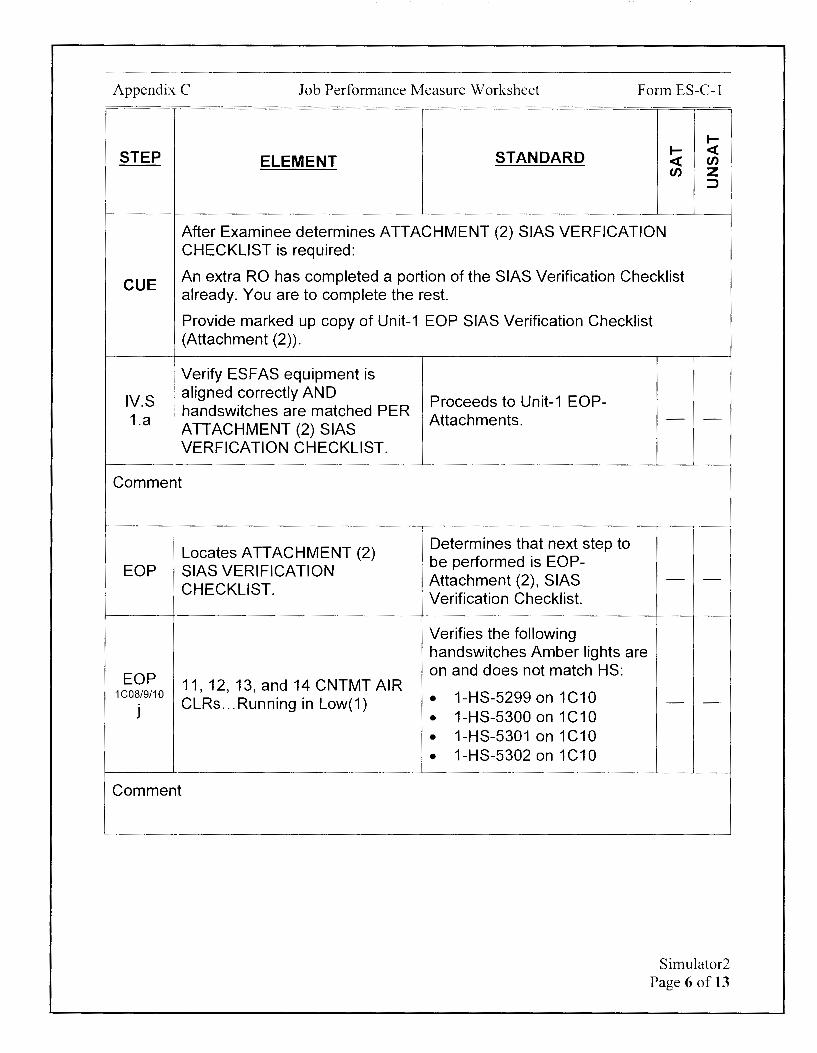
Appendix C Job Performance Measure Worksheet Form ES-C-1
I-
STEP STANDARD I- <( ELEMENT <( u,
u, z ::::>
After Examinee determines ATTACHMENT (2) SIAS VERFICATION CHECKLIST is required:
CUE An extra RO has completed a portion of the SIAS Verification Checklist already. You are to complete the rest.
Provide marked up copy of Unit-1 EOP SIAS Verification Checklist (Attachment (2)).
Verify ESFAS equipment is
IVS aligned correctly AND
Proceeds to Unit-1 EOP-, handswitches are matched PER
1.a Attachments. - -ATTACHMENT (2) SIAS VERFICATION CHECKLIST.
Comment
Locates ATTACHMENT (2) EOP SIAS VERIFICATION
CHECKLIST.
EOP 11, 12, 13, and 14 CNTMT AIR 1 COS/9/10
CLRs ... Running in Low(1) j
Comment
Determines that next step to be performed is EOP-Attachment (2), SIAS Verification Checklist.
Verifies the following handswitches Amber lights are on and does not match HS:
• 1-HS-5299 on 1C10
• 1-HS-5300 on 1C10
• 1-HS-5301 on 1C10
• 1-HS-5302 on 1C10
- -
- -
Simulator2 Page 6 of 13
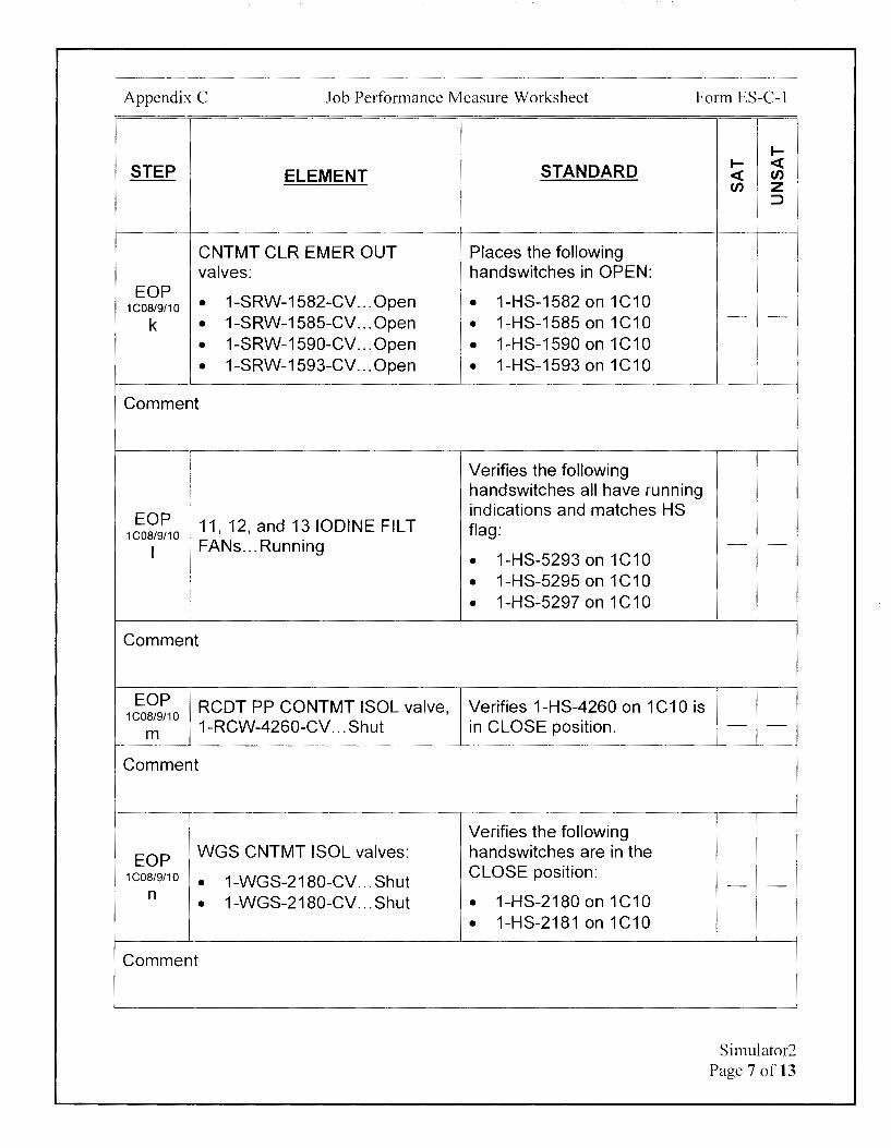
Appendix C Job Performance Measure Worksheet Form ES-C-1
STEP ELEMENT
CNTMT CLR EMER OUT valves:
EOP 1-SRW-1582-CV. .. Open 1C08/9/10 •
k • 1-SRW-1585-CV. .. Open
• 1-SRW-1590-CV. .. Open
• 1-SRW-1593-CV ... Open
Comment
i
EOP 1C08/9/10
11, 12, and 13 IODINE FIL T
I FANs ... Running
i Comment
EOP RCDT PP CONTMT ISOL valve, 1C08/9/10
1-RCW-4260-CV. .. Shut m
Comment
EOP WGS CNTMT ISOL valves: 1 C08/9/10 • 1-WGS-2180-CV. .. Shut
n 1-WGS-2180-CV. .. Shut •
Comment
STANDARD
Places the following handswitches in OPEN:
• 1-HS-1582 on 1C10
• 1-HS-1585 on 1C10
• 1-HS-1590 on 1C10
• 1-HS-1593 on 1C10
Verifies the following handswitches all have running indications and matches HS flag:
• 1-HS-5293 on 1C10
• 1-HS-5295 on 1C10
• 1-HS-5297 on 1C10
Verifies 1-HS-4260 on 1C10 is in CLOSE position.
Verifies the following handswitches are in the CLOSE position:
• 1-HS-2180 on 1C10
• 1-HS-2181 on 1C10
I-I- <( <( en en z
::::>
- -
- -
- -
- -
Simulator2 Page 7 of 13
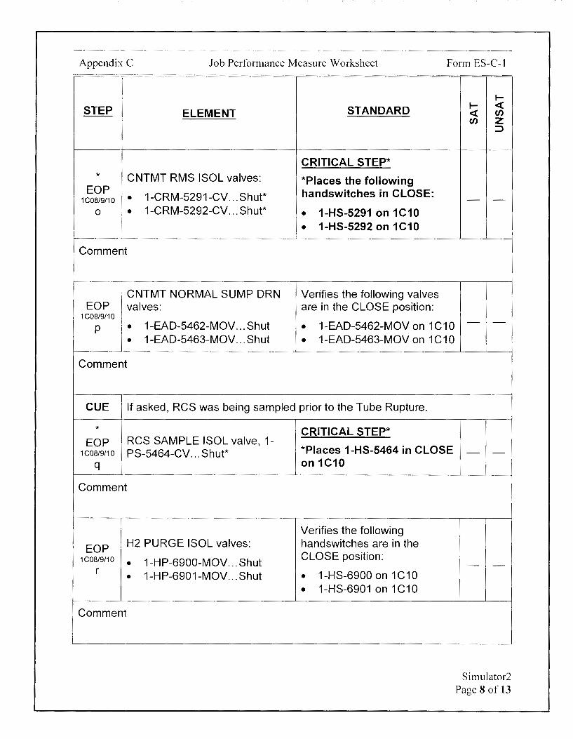
Appendix C Job Performance Measure Worksheet Form ES-C-1
STEP ELEMENT STANDARD
CRITICAL STEP* * CNTMT RMS ISOL valves: *Places the following
EOP 1-CRM-5291-CV. .. Shut* handswitches in CLOSE:
1 COS/9/10 • 0 1• 1-CRM-5292-CV. .. Shut* • 1-HS-5291 on 1C10
I 1-HS-5292 on 1C10 I • !
Comment
CNTMT NORMAL SUMP ORN Verifies the following valves EOP valves: are in the CLOSE position:
1C08/9/10
1-EAD-5462-MOV. .. Shut 1-EAD-5462-MOV on 1C10 p 1: • 1-EAD-5463-MOV. .. Shut • 1-EAD-5463-MOV on 1C10
Comment
CUE If asked, RCS was being sampled prior to the Tube Rupture.
* CRITICAL STEP* EOP RCS SAMPLE ISOL valve, 1-
*Places 1-HS-5464 in CLOSE 1COS/9/10 PS-5464-CV. .. Shut* q on 1C10
Comment
Verifies the following
EOP H2 PURGE ISOL valves: handswitches are in the 1COS/9/10 • 1-HP-6900-MOV. .. Shut CLOSE position:
r 1-HP-6901-MOV. .. Shut 1-HS-6900 on 1C10 • • • 1-HS-6901 on 1C10
Comment
I-I- <( <( en en z
:::::,
- -
- -
- -
- -
Simulator2 Page 8 of 13

Appendix C Job Performance Measure Worksheet Form ES-C-1
STEP ELEMENT
EOP LID CNTMT ISOL valves:
1C07 • 1-CVC-515-CV ... Shut a • 1-CVC-515-CV. .. Shut
Comment
EOP : 11, 12, and 13 CHG
1C07 ! PPs ... Running
b
:
Comment
EOP VCT OUT valve, 1-CVC-501-
1C07 MOV ... Shut
C
Comment
EOP VCT M/U valve, 1-CVC-512-
1C07 CV. .. Shut
d
Comment
EOP BA DIRECT M/U valve, 1-CVC-
1C07 514-MOV ... Open
e
Comment
STANDARD
Verifies the following handswitches are in the CLOSE position:
• 1-HS-2515 on 1C07
• 1-HS-2516 on 1C07
Verifies the following handswitches all have running indications.
• 1-HS-224X on 1 CO?
• 1-HS-224Y on 1 CO?
• 1-HS-224Z on 1 CO?
Verifies 1-HS-2501 on 1C07 is in CLOSE.
Verifies 1-HS-2512 on 1C07 is in CLOSE.
Verifies 1-HS-2514 on 1 CO? indicates OPEN.
1--1-- <C <C en en z
:::>
- -
- -
- -
- -
- -
Simulator2 Page 9 of 13

Appendix C Job Performance Measure Worksheet
STEP ELEMENT STANDARD
Verifies the following
EOP handswitches both have
1C07 11 and 12 BA PPs ... Running running indications.
f • 1-HS-226X on 1 CO?
• 1-HS-2226 on 1 CO?
Comment
Verifies the following
EOP BAST GRAVITY FD valves: handswitches both indicate I OPEN: 1C07 1. 1-CVC-508-MOV. .. Open
g : . 1-CVC-509-MOV. .. Open • 1-HS-2508 on 1 CO?
• 1-HS-2509 on 1 CO?
Comment
EOP BAST RECIRC valves: Places the following handswitches in CLOSE:
1C07 • 1-CVC-510-CV ... Shut 1-HS-2510 on 1C07 h • • 1-CVC-511-CV. .. Shut 1-HS-2511 on 1C07 •
Comment
CRITICAL STEP* * RCP BLEED-OFF ISOL valves: *Places the following
EOP 1C07 • 1-CVC-505-CV. .. Shut* handswitches in CLOSE:
I • 1-CVC-506-CV. .. Shut* • 1-HS-2505 on 1 C07 • 1-HS-2506 on 1 C07
Comment
Form ES-C-1
I-I- <( <( en en z
:)
- -
- -
- -
- -
Simulator2 Page 10 of 13
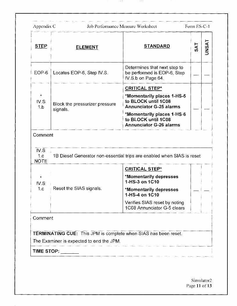
Appendix C Job Performance Measure Worksheet Form ES-C-1
I-
STEP STANDARD I- <( ELEMENT <( en
en z ::,
Determines that next step to EOP-6 Locates EOP-6, Step IVS. be performed is EOP-6, Step - -
IVS.b on Page 64.
CRITICAL STEP*
* *Momentarily places 1-HS-5 IVS Block the pressurizer pressure
to BLOCK until 1 COB 1.b Annunciator G-25 alarms
signals. - -*Momentarily places 1-HS-6 to BLOCK until 1 COB Annunciator G-26 alarms
Comment
IVS 1.c 1 B Diesel Generator non-essential trips are enabled when SIAS is reset
NOTE
I CRITICAL STEP*
* *Momentarily depresses i
1-HS-3 on 1C10 IVS 1.c Reset the SIAS signals. *Momentarily depresses
1-HS-4 on 1C10
Verifies SIAS reset by noting 1 COB Annunciator G-5 clears
Comment
TERMINATING CUE: This JPM is complete when SIAS has been reset.
The Examiner is expected to end the JPM.
TIME STOP:
- -
Simulator2 Page 11 of 13

Appendix C Job Performance Measure Worksheet
Verification of Completion
Job Performance Measure Number: Simulator2
Examinee:
NRC Examiner:
Date Performed:
Facility Evaluator: ________________ _
Number of Attempts: ----------------Time to Complete: -----------------Follow up Question(s):
Examinee Response:
Result: SATISFACTORY UNSATISFACTORY -- --
Examiner's Signature and Date:
Form ES-C-1
Simulator2 Page 12 of 13
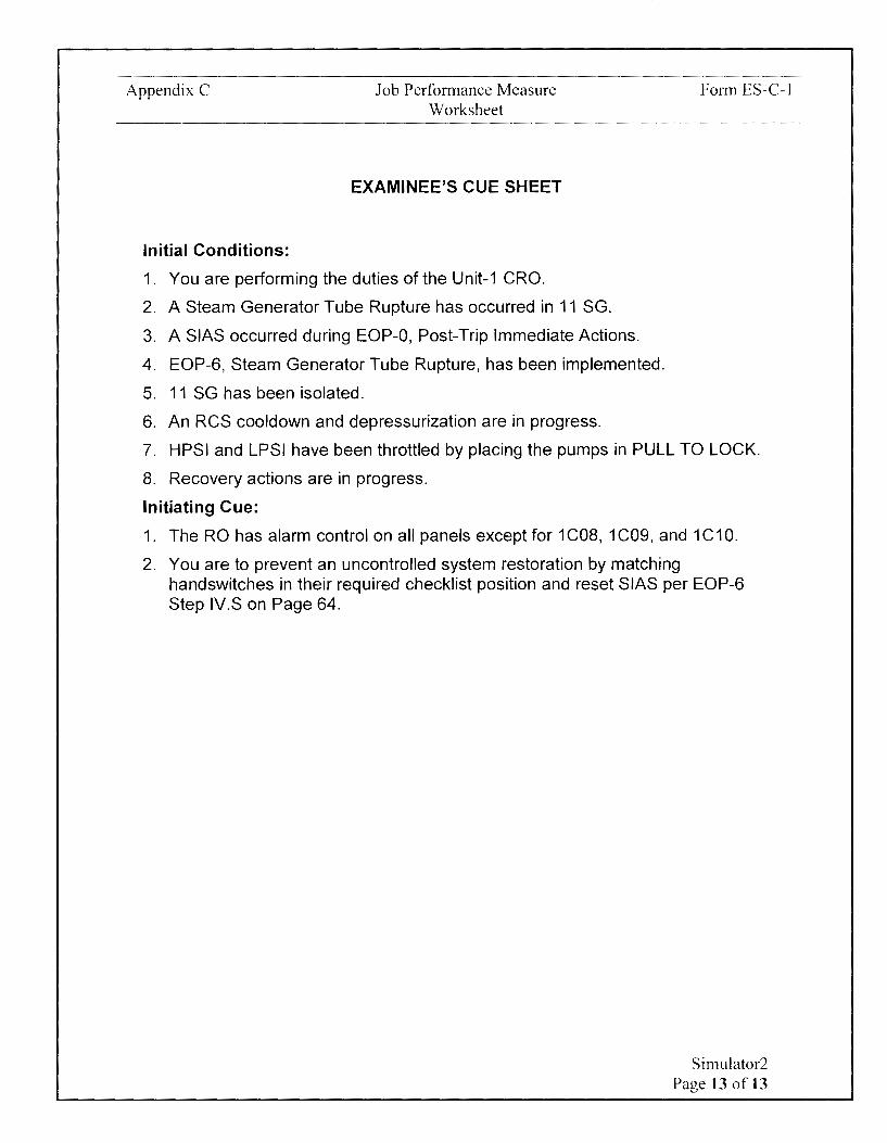
Appendix C Job Performance Measure Worksheet
EXAMINEE'S CUE SHEET
Initial Conditions:
1. You are performing the duties of the Unit-1 CRO.
2. A Steam Generator Tube Rupture has occurred in 11 SG.
3. A SIAS occurred during EOP-0, Post-Trip Immediate Actions.
4. EOP-6, Steam Generator Tube Rupture, has been implemented.
5. 11 SG has been isolated.
6. An RCS cooldown and depressurization are in progress.
Form ES-C-1
7. HPSI and LPSI have been throttled by placing the pumps in PULL TO LOCK.
8. Recovery actions are in progress.
Initiating Cue:
1. The RO has alarm control on all panels except for 1C08, 1C09, and 1C10.
2. You are to prevent an uncontrolled system restoration by matching handswitches in their required checklist position and reset SIAS per EOP-6 Step IV.Son Page 64.
Simulator2 Page 13 of 13
Calvert Cliffs Nuclear Power Plant
2018 NRC Initial Licensed Operator Exam
JPM-Simulator3
Appendix C Job Performance Measure Worksheet
Facility: Calvert Cliffs 1 & 2
Alternate Path: Yes
Task Number: 052/061.016
Task Title: Fill SITs using various flowpaths
Task Standard:
Form ES-C-1
JPM Number: Simulator3
This JPM is complete when 11A SIT level has been returned to normal and 11A SIT pressure has been restored to normal following the vent line leak.
Time Critical Task: No
K/A Reference: 006A 1.13 (3.5/3.7)
Method of Testing: Actual Performance-Simulator
Validation Time: 18 minutes
References and Tools Required:
1. Ol-3A Safety Injection and Containment Spray
2. 1C09-ALM, ESFAS 12 Alarm Manual
JPM Setup Instructions:
1. IC with startup in progress and power -1 E-4%.
2. Ol-3A, Safety Injection and Containment Spray, is completed with placekeeping indicating that Steps 6.3.A and B.1-12 are completed and identifies all of the associated 11A SIT valves operated (617-MOV, etc)
3. CCV tag on 1-HS-3618 on 1 COS.
4. CCV tag on 1-HIC-3618 on 1C08.
5. CCV tag on 1-HS-3617 on 1 COS.
6. Establish PPC screen with following trends:
• RWT Level (L4142)
• QT Pressure (P116)
• QT Level (L 116)
7. Establish level of -188" in 11A SIT by performing Ol-3A, Step 6.7.
8. Ensure pressure is -213 PSIG in 11A SIT. If pressure needs to be adjusted, raise pressure by performing Ol-3A, Step 6.1.
9. Verify the 11A SIT PRESS alarm on 1C09 is not in.
10. Pump 11 RCDT per Ol-17C-2, Step 6.14.
11. Start 11 HPSI Pump.
Simulator3 Page 2 of 16

Appendix C Job Performance Measure Worksheet Form ES-C-1
12.Verify 1-HIC-361S controller output on 1COS is <0%.
13. Place 1-HS-361 Son 1 COS to OPEN. The valve indication should indicate closed due to HIC-361 S output.
14. Using dry erase marker, mark current SIT level indications on 1 COS and 1 C09.
15. Overrides:
a. P1 COS 1 CV613 L TGREEN to On - -b. P1 COS 1 CV613 L TRED to On - -
C. P1 COS 1 HS3613 to OPEN on event 1
d. P1COS 1HS3613 to CLOSE on event 2
e. P1 COS 1 Pl311A MT to 221.0 on event 3 - -
f. P1 COS 1 PIA311 MT to 222.0 on event 3 - -g. P1 C09 H01 L TON to Off on event 3 - -
h. P1 COS 1 Pl311A MT to 220.0 on event 4 - -I. P1 COS 1 PIA311 MT to 221.0 on event 4
16. Insight Table open to fast fill 11A SIT to -192" (Cell 1026 to 0.547.)
Simulator3 Page 3 of 16
Appendix C Job Performance Measure Worksheet Form ES-C-1
Directions to the Examinee:
I will explain the initial conditions, which steps to simulate or discuss, and provide initiating cues. When you complete the task successfully, the objective for this job performance measure will be satisfied.
Hand Examinee's Cue Sheet to Examinee at this time.
Initial Conditions:
1. You are performing the duties of the Unit-1 CRO.
2. Unit-1 is in Mode 2 and continuing with a startup following a Forced Outage.
3. 11A Safety Injection Tank (SIT) level is low at 188" and needs to be filled.
4. Instrument Maintenance is preparing a Troubleshooting Plan to evaluate 1 C09 intermediate indication for 11A SIT VENT CV, 1-HS-3613.
5. Ol-3A, Safety Injection and Containment Spray, was implemented to fill 11A SIT.
6. Plant Computer trends have been established to monitor RWT level, Quench Tank pressure, and Quench Tank level.
7. 11 HPSI Pump was started and the Aux HPSI Header flushed per 01-3A, Safety Injection and Containment Spray. Ol-3A Steps 6.3.B.1-12 have been completed.
8. 11A SIT Checkvalve Leakage CV, 1-Sl-618-CV, is currently shut with 1-HIC-3618 output at 0% and valve handswitch, 1-HS-3618, in OPEN.
9. Chemistry reports that HPSI header boron concentration is 2505 PPM.
Initiating Cue:
1. You are to continue with Ol-3A, Safety Injection and Containment Spray, Step 6.3.B.13 on page 17 and fill 11A SIT to -193".
2. Are there any questions? You may begin.
Simulator3 Page 4 of 16
Appendix C Job Performance Measure Worksheet Form ES-C-1
I-
STEP STANDARD I- <( ELEMENT <( en
en z ::>
TIME START:
CUE After Examinee reviews Cue Sheet, provide the examinee with a copy of 01-
1 3A-1 with appropriate placekeeping marks.
i Locates AOP-Ol-3A, Step Determines that next step to
Ol-3A be performed is 6.3.B.13 on ! 6.3.B.13 - -
Page 17.
CHECK HPSI header boron Evaluates Chemistry HPSI concentration meets the
6.3 following: (TS SR 3.5.1.4) header sample results.
B.13 HPSI header boron Determines 2505 PPM is - -• within limits based on Cue
concentration is between
I 2450 and 2700 PPM Sheet.
Comment -
CUE Chemistry has recorded the HPSI Header boron concentration in eSOMS.
6.3 RECORD the boron Determines that step has been
B.14 concentration is the CRO Daily completed by the Chemistry - -Log based on the Cue.
Comment
6.3 The HPSI header isolation must be the same to ensure the sample is B.15
CAUTION representative of the boron concentration to the fill the SIT(s).
Simulator3 Page 5 of 16
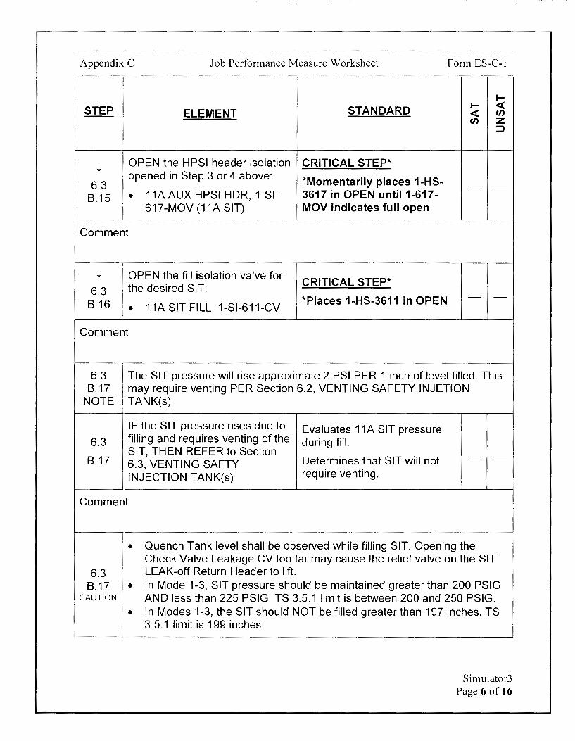
Appendix C Job Performance Measure Worksheet Form ES-C-1
I-
STEP STANDARD I- <( ELEMENT <( en
en z :::>
OPEN the HPSI header isolation CRITICAL STEP* *
6.3 opened in Step 3 or 4 above: *Momentarily places 1-HS-
11A AUX HPSI HOR, 1-SI- 3617 in OPEN until 1-617- - -8.15 •
617-MOV (11A SIT) MOV indicates full open
Comment
* OPEN the fill isolation valve for the desired SIT: CRITICAL STEP*
6.3 *Places 1-HS-3611 in OPEN - -
8.16 1 .•
11A SIT FILL, 1-Sl-611-CV
Comment
6.3 The SIT pressure will rise approximate 2 PSI PER 1 inch of level filled. This 8.17 may require venting PER Section 6.2, VENTING SAFETY INJETION
NOTE TANK(s)
IF the SIT pressure rises due to Evaluates 11A SIT pressure 6.3 filling and requires venting of the during fill.
8.17 SIT, THEN REFER to Section
Determines that SIT will not - -6.3, VENTING SAFTY INJECTION TANK(s) require venting.
Comment
•
6.3 8.17 •
CAUTION
•
Quench Tank level shall be observed while filling SIT. Opening the Check Valve Leakage CV too far may cause the relief valve on the SIT LEAK-off Return Header to lift. In Mode 1-3, SIT pressure should be maintained greater than 200 PSIG AND less than 225 PSIG. TS 3.5.1 limit is between 200 and 250 PSIG. In Modes 1-3, the SIT should NOT be filled greater than 197 inches. TS 3.5.1 limit is 199 inches.
Simulator3 Page 6 of 16
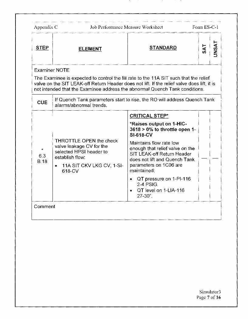
Appendix C Job Performance Measure Worksheet Form ES-C-1
STEP ELEMENT
Examiner NOTE
STANDARD I
I- <( <( ff) ff) z
::>
The Examinee is expected to control the fill rate to the 11A SIT such that the relief valve on the SIT LEAK-off Return Header does not lift. If the relief valve does lift, it is not intended that the Examinee address the abnormal Quench Tank conditions.
CUE j If Quench Tank parameters start to rise, the RO will address Quench Tank i alarms/abnormal trends.
* 6.3
8.18
i
I
: THROTTLE OPEN the check , valve leakage CV for the
selected HPSI header to establish flow:
• 11A SIT CKV LKG CV, 1-Sl-618-CV
Comment
CRITICAL STEP*
*Raises output on 1-HIC-3618 > 0% to throttle open 1-Sl-618-CV
Maintains flow rate low enough that relief valve on the SIT LEAK-off Return Header does not lift and Quench Tank parameters on 1 C06 are maintained:
• QT pressure on 1-Pl-116 2-4 PSIG.
• QT level on 1-LIA-116 27-30".
Simulator3 Page 7 of 16

Appendix C Job Perfo1mance Measure Worksheet Form ES-C-1
~
STEP STANDARD ~ <( ELEMENT <( en
en z ::,
Once 11A SIT level is rising:
Simulator will be forwarded in time. CUE Direct Simulator Driver to fast fill the 11A SIT to 192" using Insight Table.
Direct Simulator Driver to initiate Event 4. This will raise 11A SIT pressure.
11A SIT level is now 192" and rising.
CRITICAL STEP*
Monitors SIT level on 1-LI-311A.
Raises 11A SIT level to 192-
* WHEN at the desired level or 194".
6.3 SIT pressure approaches 225 *Once at required level, PSIG, THEN SHUT the check
B.19 valve leakage CV opened.
shuts 1-Sl-618-CV by:
Lowering output on 1-HIC-3618 to< 0%
AND/OR
Places 1-HS-3618 to CLOSE i
Comment
* . SHUT the SIT fill isolation valve CRITICAL STEP*
6.3 \ opened. B.20 *Places 1-HS-3611 to CLOSE
Comment
6.3 IF additional SIT(s) are to be
B.21 filled, THEN REPEAT Steps 16- Determines step is N/A 20 to fill each additional SIT.
Comment
- -
- -
- -
Simulator3 Page 8 of 16

Appendix C Job Performance Measure Worksheet Form ES-C-1
STEP ELEMENT
* 6.3
SHUT the MAIN or AUX HPSI HOR isolation opened.
B.22
Comment
* 6.3
STOP running HPSI Pump.
B.23 • 11 HPSI Pump, 1-HS-301X
Comment
IF ANY SI Check Valve Leak
6.3 Indicators, 1-PIA-319, 329,339,
B.24 I or 349 indicate > 300 PISG 1 THEN PERFORM the following I to lower pressure to < 300 PSIG:
Comment
* 6.3 OPEN LEAKOFF TO RCDT, 1-
B.24 Sl-661-CV. a
Comment
STANDARD
CRITICAL STEP*
*Momentarily places 1-HS-3617 to CLOSE until 1-SI-617-MOV indicates closed
CRITICAL STEP*
*Momentarily places 1-HS-301X in STOP
Evaluates pressure indicators and determines 1-PIA-319, is reading > 300 PSIG.
Determines step is applicable.
CRITICAL STEP*
*Places 1-HS-3661 to OPEN
I-I- <( <( en en z
::J
- -
- -
- -
- -
Simulator3 Page 9 of 16
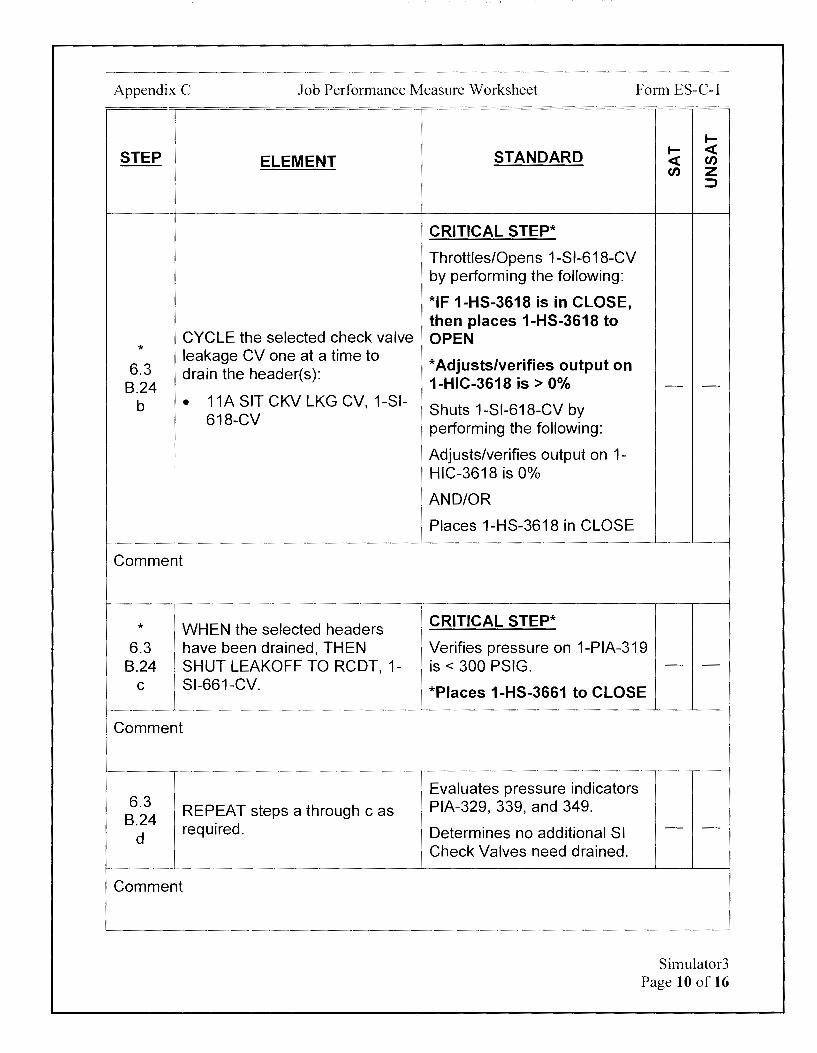
Appendix C Job Performance Measure Worksheet Form ES-C-1
STEP ELEMENT
CYCLE the selected check valve * leakage CV one at a time to
6.3 drain the header(s): 8.24
b • 11A SIT CKV LKG CV, 1-SI-618-CV
Comment
* WHEN the selected headers 6.3 have been drained, THEN
8.24 SHUT LEAKOFF TO RCDT, 1-C Sl-661-CV.
Comment
6.3 REPEAT steps a through c as
8.24 required.
d
Comment
I-
STANDARD I- <( <( en en z
::>
CRITICAL STEP*
Th rattles/Opens 1-S 1-618-CV by performing the following:
*IF 1-HS-3618 is in CLOSE, then places 1-HS-3618 to OPEN
*Adjusts/verifies output on 1-HIC-3618 is> 0% - -
Shuts 1-Sl-618-CV by performing the following:
Adjusts/verifies output on 1-HIC-3618 is 0%
AND/OR
Places 1-HS-3618 in CLOSE
CRITICAL STEP*
Verifies pressure on 1-PIA-319 is < 300 PSIG. - -
*Places 1-HS-3661 to CLOSE
Evaluates pressure indicators PIA-329, 339, and 349.
Determines no additional SI Check Valves need drained.
- -
Simulator3 Page 10 of 16
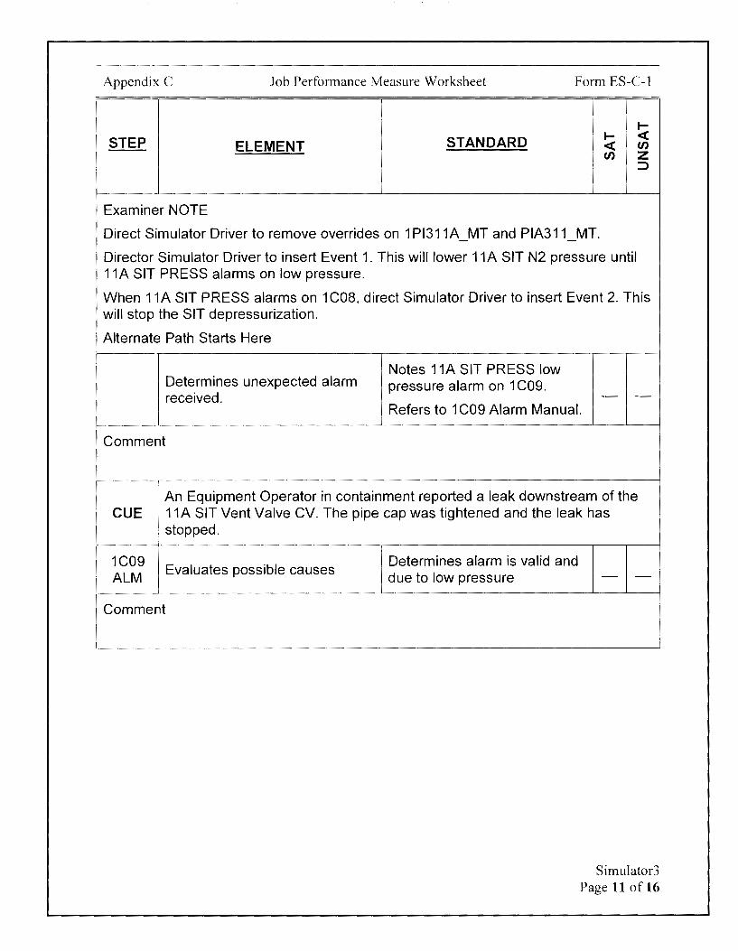
Appendix C Job Performance Measure Worksheet Form ES-C-1
I-
STEP STANDARD I- < ELEMENT < en en z
::,
Examiner NOTE
Direct Simulator Driver to remove overrides on 1 Pl311A MT and PIA311 MT. -
Director Simulator Driver to insert Event 1. This will lower 11A SIT N2 pressure until 11A SIT PRESS alarms on low pressure.
When 11A SIT PRESS alarms on 1 COS, direct Simulator Driver to insert Event 2. This will stop the SIT depressurization.
Alternate Path Starts Here
Notes 11A SIT PRESS low Determines unexpected alarm pressure alarm on 1 C09. received. - -
Refers to 1 C09 Alarm Manual.
Comment
An Equipment Operator in containment reported a leak downstream of the CUE
1 11A SIT Vent Valve CV. The pipe cap was tightened and the leak has
! stopped.
1C09 Evaluates possible causes
ALM
Comment
Determines alarm is valid and due to low pressure - -
Simulator3 Page 11 of 16
Appendix C Job Performance Measure Worksheet Form ES-C-1
STEP ELEMENT STANDARD
CUE The Unit Supervisor will evaluate Tech Spec 3.5.1.
Restore 11A SIT pressure to -220 PSIG per Ol-3A.
RAISE 11A SIT pressure by 1C09 raising N2 pressure or raising Refers to Ol-3A and ALM SIT level (whichever is more determines Step 6.1 will be
1 practical), PER Ol-3A, Safety used to restore pressure in Injection and Containment 11A SIT. Spray.
Comment
i
6.1 [ Initial Conditions Evaluates 11A SIT pressure
A.1 · SIT pressure is less than 225 on 1-Pl-311A and determines
PSIG. pressure is <225 PSIG
Comment
6.1 IF in Cold Shutdown, THEN SIT Determines step is NIA
A.2 pressure is less than 215 PSIG.
Comment
CUE After the direction is given to the ABO, O-N2-236 is open.
* Procedure CRITICAL STEP* 6.1 OPEN U-1 SAFETY INJ TKS N2 *Directs ABO to open O-N2-8.1 SUPP VLV, O-N2-236 236
Comment
I-I- < < en en z
::::>
- -
- -
- -
- -
Simulator3 Page 12 of 16
Appendix C Job Performance Measure Worksheet Form ES-C-1
I-
STEP STANDARD I- <( ELEMENT <( en
en z ::::>
CUE If asked, the Unit Supervisor has assigned an Extra RO as the dedicated operator and the Extra RO is stationed.
Determines that Unit STATION a dedicated operator Supervisor has assigned and in the Control Room to isolate stationed a dedicated operator
6.1 the penetration by closing the N2 based on Cue 8.2 supply control valve, if - -
Containment isolation is OR
required. Designates themselves as the dedicated operator.
Comment
6.1 To avoid excessive SIT pressure during plant heatup, maximum SIT
8.3 NOTE
pressure in Cold Shutdown should be limited to 215 PSIG.
6.1 I
: In Modes 1, 2, and 3, SIT pressure should be maintained greater than 200 8.3 PSIG and less than 225 PSIG.
CAUTION
i OPEN the N2 Supply control
* valve for the SIT to be CRITICAL STEP*
6.1 pressurized: *Places 1-HS-3612 to OPEN - -
8.3 • 11A SIT N2 SUPP, 1-Sl-612-CV
Comment
Simulator3 Page 13 of 16
Appendix C Job Performance Measure Worksheet Form ES-C-1
I-
STEP STANDARD I- <( ELEMENT <( en
en z ::>
Examiner NOTE
SIT pressure rises very slowly when raising pressure with N2.
After 1-Sl-612-CV is open and the Examinee has determined 11A SIT pressure is rising:
CUE Simulator will be forwarded in time. Direct Simulator Driver to insert Event 3, which will fast pressurize 11A SIT to 220 PSIG. 11A SIT pressure is now 220 PSIG.
CRITICAL STEP*
* WHEN the SIT being
Determines 11A SIT pressure 6.1
pressurized is at the desired is restored to desired pressure pressure, THEN SHUT the SIT - -
8.4 N2 supply control valve opened
based on Cue.
*Places 1-HS-3612 to CLOSE
Comment
TERMINATING CUE: This JPM is complete when 11A SIT level has been returned to normal and 11A SIT pressure has been restored to normal following the vent line leak.
The Examiner is expected to end the JPM.
TIME STOP:
Simulator3 Page 14 of 16
Appendix C Job Performance Measure Worksheet
Verification of Completion
Job Performance Measure Number: Simulator3
Examinee:
NRC Examiner:
Date Performed:
Facility Evaluator: ----------------
Number of Attempts: ----------------
Time to Complete: ________________ _
Follow up Question(s):
Examinee Response:
Result: SATISFACTORY __ UNSATISFACTORY __
Examiner's Signature and Date:
Form ES-C-1
Simulator3 Page 15 of 16
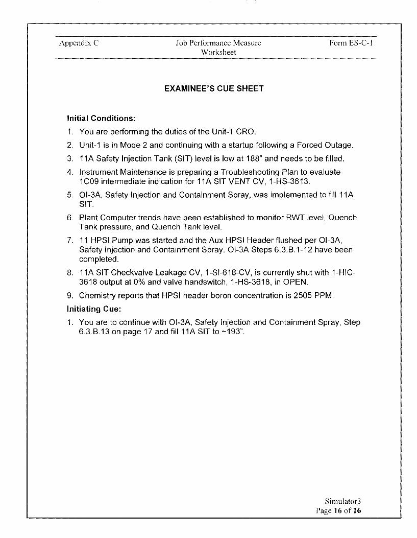
Appendix C
Initial Conditions:
Job Performance Measure Worksheet
EXAMINEE'S CUE SHEET
1. You are performing the duties of the Unit-1 CRO.
Form ES-C-1
2. Unit-1 is in Mode 2 and continuing with a startup following a Forced Outage.
3. 11A Safety Injection Tank (SIT) level is low at 188" and needs to be filled.
4. Instrument Maintenance is preparing a Troubleshooting Plan to evaluate 1C09 intermediate indication for 11A SIT VENT CV, 1-HS-3613.
5. 01-3A, Safety Injection and Containment Spray, was implemented to fill 11A SIT.
6. Plant Computer trends have been established to monitor RWT level, Quench Tank pressure, and Quench Tank level.
7. 11 HPSI Pump was started and the Aux HPSI Header flushed per Ol-3A, Safety Injection and Containment Spray. Ol-3A Steps 6.3.8.1-12 have been completed.
8. 11A SIT Checkvalve Leakage CV, 1-Sl-618-CV, is currently shut with 1-HIC-3618 output at 0% and valve handswitch, 1-HS-3618, in OPEN.
9. Chemistry reports that HPSI header boron concentration is 2505 PPM.
Initiating Cue:
1. You are to continue with Ol-3A, Safety Injection and Containment Spray, Step 6.3.8.13 on page 17 and fill 11A SIT to -193".
Simulator3 Page 16 of 16

Calvert Cliffs Nuclear Power Plant
2018 NRC Initial Licensed Operator Exam
JPM-Simulator4

Appendix C Job Performance Measure Worksheet
Facility: Calvert Cliffs 1 & 2
Alternate Path: Yes
Task Number: 093.015
Task Title: Verify Automatic Turbine trip on Unit-2
Form ES-C-1
JPM Number: Simulator4
Task Standard: This JPM is complete when 500 KV Line voltage is initially raised to -530 KV and Turbine Trip is performed in EOP-0.
KIA Reference: 045A3.11 (2.6/2.9)
Method of Testing: Actual Performance-Simulator
Validation Time: 15 minutes
References and Tools Required:
1. Ol-43A, Main Turbine and Generator/Exciter Operation
2. EOP-0, Post-Trip Immediate Actions
JPM Setup Instructions:
1. Reset to IC-34 (Both Units 100%, MOC).
2. Bottom Turbine Ovation Screen on 2C02 on Control display.
3. Top Turbine Ovation Screen on 2C02 on Control display with 9.9% ramp rate.
4. Lower 500KV Sensitive Volts (O-El-1001) on 1C01 to 526 KV by lowering MVARs on both Units.
5. Verify both Unit-1 and Unit-2 MVARs are - matched in the LAG after the 500 KV Sensitive Volt adjustment.
6. Two mimics available to the Simulator Driver to indicate 2-MS-4019-CV valve position on Turbine Ovation screens is open (red).
7. Events
a. P1C01_11GEVRAUTO_SWRAISE (U-1 Voltage Regulator Raised) on event 1
b. P1 C01_21 GENEXCBK_SWTRIP (U-2 Generator Field Stopped) on event 4
Simulator4 Page 2 of 17
Appendix C Job Performance Measure Worksheet
8. Overrides:
a. P2C17 22BA MT to 500.00000 on event 1 - -
b. P2C17 22AA MT to 500.00000 on event 1 - -
c. P1 C20 21 BZA MT to 490.00000 on event 1 - -
d. P1 C20 21AZA MT to 490.00000 on event 1 - -
e. P1C19 24BZB MT to 600.00000 on event 1 - -
f. P2C 17 23B MT to 4.20000 on event 1 - -
g. set ISEXT_GRID_V=510 on event 2
h. P1 C01 A09 L TON to On on event 2 - -
1. P1 C01 A02 L TON to On on event 2 delete in 2
J. P1 C01 A02 L TON after 6 to On on event 2 delete in 10
k. P1C01 A10 LTONafter10to0nonevent2 - -
I. P2C02 2HS8250 after 15 to TRIP on event 2
m. P1 C01 MGS2TERMV MT to 21.00000 on event 2 - -
n. P1C07 1RR202 to 75.00000 on event 2
o. P1 C01 MGS2K41 M L TGRE to Off on event 2 - -p. P1C01_MGS2K41M_LTRED to On on event 2
q. P1 C01_MGS2K41 M_L TGRE to On event 4
r. P1 C01 MGS2K41 M L TRED to Off on event 4 - -s. P1 CO? 1 RR202 to O on event 4
t. P1 C01 MGS2TERMV MT to O on event 4 - -9. Verify Schedule is in RUN
10. Verify Events is Open.
Fom1 ES-C-1
Simulator4 Page 3 of 17
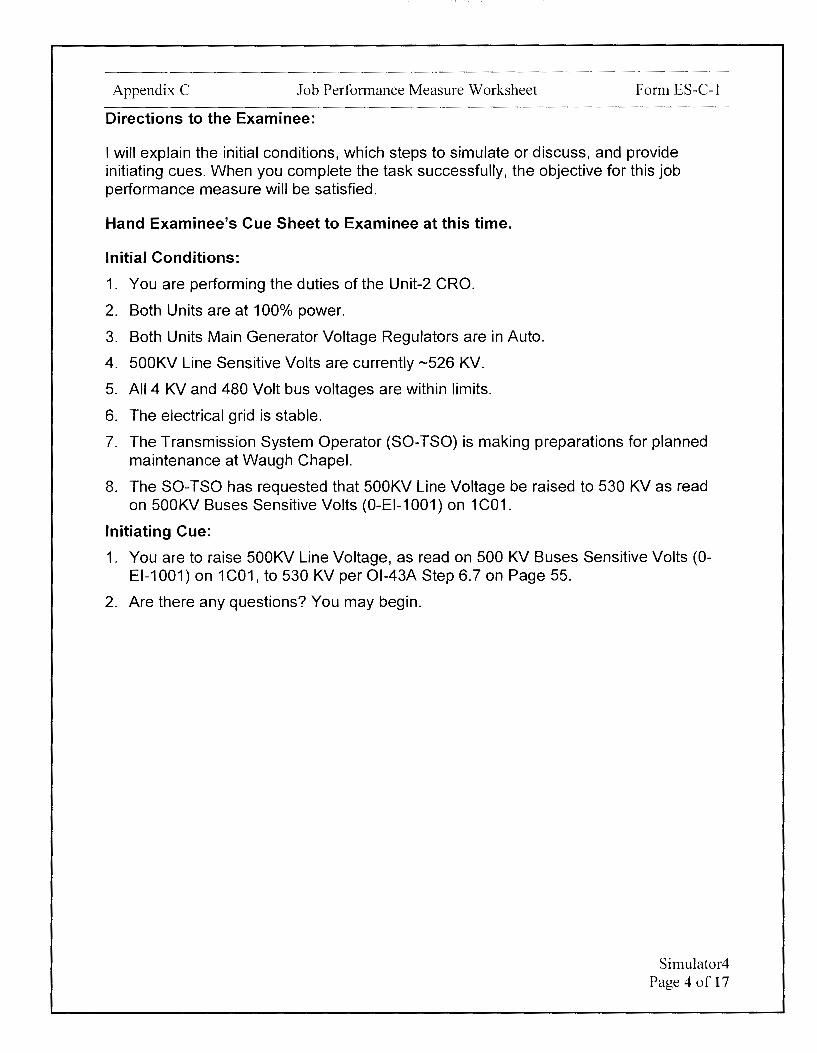
Appendix C Job Performance Measure Worksheet Form ES-C-1
Directions to the Examinee:
I will explain the initial conditions, which steps to simulate or discuss, and provide initiating cues. When you complete the task successfully, the objective for this job performance measure will be satisfied.
Hand Examinee's Cue Sheet to Examinee at this time.
Initial Conditions:
1. You are performing the duties of the Unit-2 CRO.
2. Both Units are at 100% power.
3. Both Units Main Generator Voltage Regulators are in Auto.
4. 500KV Line Sensitive Volts are currently -526 KV.
5. All 4 KV and 480 Volt bus voltages are within limits.
6. The electrical grid is stable.
7. The Transmission System Operator (SO-TSO) is making preparations for planned maintenance at Waugh Chapel.
8. The SO-TSO has requested that 500KV Line Voltage be raised to 530 KV as read on 500KV Buses Sensitive Volts (O-El-1001) on 1 C01.
Initiating Cue:
1. You are to raise 500KV Line Voltage, as read on 500 KV Buses Sensitive Volts (OEl-1001) on 1C01, to 530 KV per Ol-43A Step 6.7 on Page 55.
2. Are there any questions? You may begin.
Simulator4 Page 4 of 17

Appendix C Job Performance Measure Worksheet Form ES-C-1
~
STEP STANDARD ~ <t ELEMENT <t en
en z ::J
TIME START:
CUE After Examinee reviews Cue Sheet, provide the examinee with a copy of 01-43A-2.
Determines that next step to Locates Ol-43A Step 6.7. be performed is Ol-43A Step - -
I 6.7 on Page 55. I
6.7 I
A ' Initial Conditions
6.7 Initial Conditions A.1 Anyone of the following occurs:
'
6.7 I System Operator-Transmission Determines initial condition is
A.1 I
• System Operator (SO-TSO) has met based on Examinee Cue
1st j requested line voltage be - -bullet adjusted.
Sheet.
Comment
6.7 It is desired to adjust 13 KV or 4
A.1 Determines initial condition is 2nd
KV bus voltage by adjusting 500 N/A. - -
bullet KV line voltage.
Comment
6.7 Procedure
B 6.7
Steps 1.c and 1.d can be performed in any order and as many times as B.1 NOTE needed to obtain proper line voltage.
6.7 Line voltage should be maintained between 514.5-535.5 KV (525_±2%) to B.1 assure PJM voltage and stability operating guidelines.
CAUTION
Simulator4 Page 5 of 17
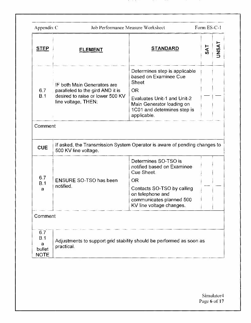
Appendix C Job Performance Measure Worksheet Form ES-C-1
._ STEP STANDARD
._ < ELEMENT < en en z
::J
Determines step is applicable based on Examinee Cue
IF both Main Generators are Sheet
6.7 paralleled to the gird AND it is OR B.1 , desired to raise or lower 500 KV - -
Evaluates Unit-1 and Unit-2 line voltage, THEN: Main Generator loading on
1 C01 and determines step is applicable.
Comment
CUE If asked, the Transmission System Operator is aware of pending changes to 500 KV line voltage.
Determines SO-TSO is notified based on Examinee Cue Sheet.
6.7 ENSURE SO-TSO has been OR
B.1 notified. - -
a Contacts SO-TSO by calling on telephone and communicates planned 500 KV line voltage changes.
Comment
6.7 B.1
Adjustments to support grid stability should be performed as soon as a
bullet NOTE
practical.
Simulator4 Page 6 of 17
Appendix C Job Performance Measure Worksheet Form ES-C-1
!
'
I-
STEP ELEMENT STANDARD I- <( <( u, u, z
::>
IF notified to make adjustment to
6.7 support grid stability, AND the
B.1 adjustment can NOT be
a performed with 30 minutes, Determines step is NIA. - -
bullet THEN NOTIFY the SO-TSO why the adjustment is NOT achievable.
Comment
Evaluates 500 KV Buses
IF line Voltage is outside 514.5- Sensitive Line Volts on 0-EI-
535.5 KV (525_±2%), THEN 1001 on 1 C01 and determines
PERFORM the following: voltage is within limits and 6.7
(1) CONTACT SO-TSO for step is NIA
B.1 direction. OR
b - -
(2) ENSURE a log entry made in Determines 500 KV line
Control Room logs noting Line voltage is within limits based
Voltage outside band. on Examinee Cue Sheet.
Determines step is N/A.
Comment
6.7 B.1 Reactive load should be maintained in the lag direction when the Voltage
C
NOTE 6.7 B.1
C
Regulator is in Manual.
ADJUST U-1 Voltage Regulator as follows:
Simulator4 Page 7 of 17

Appendix C Job Performance Measure Worksheet Form ES-C-1
I-
STEP STANDARD I- < ELEMENT < en
en z
I
:)
Examiner NOTE
Examinee is allowed to adjust either Units Voltage Regulator in either order (i.e. Unit-1 first or Unit-2 first). Examinee is allowed to adjust either Units Voltage Regulator multiple times to achieve the desired 500KV line voltage. The Critical Tasks are met when Voltage Regulator adjustments are completed and the 500 KV Buses Sensitive Line Volts on O-El-1001 at 1C01 reads 529-531 KV.
CRITICAL STEP*
Determines U-1 Voltage Regulator is in Auto based on Examinee Cue Sheet or 1-CS-43 position on 1 C01.
* IF U-1 Voltage Reg is in AUTO, *Momentarily places 1-CS-90 in RAISE to raise 500KV line
6.7 THEN ADJUST 11 GEN AUTO voltage B.1 VOLT CONTR, 1-CS-90, to
C achieve approximately one-half If U-1 Voltage Regulator is first
1st of the required change in line to be adjusted, then first 500
bullet voltage. KV line voltage change is from 526 KV to -527 -529 KV.
*If Unit-1 Voltage Regulator is the last one adjusted:
500 KV Buses Sensitive Line Volts on O-El-1001 at 1C01 read 529-531 KV
Comment
- -
Simulator4 Page 8 of 17
Appendix C Job Performance Measure Worksheet Form ES-C-1
.... STEP STANDARD .... <(
ELEMENT <( en en z
! :::,
6.7 IF U-1 Voltage Reg is in
B.1 • MANUAL, THEN ADJUST 11
C GEN MANUAL VOLT CONTRO, Determines step is NIA. 1-CS-70, to achieve - -
2nd , approximately one-half of the
bullet !
1
required change in line voltage.
Comment
6.7 B.1 Reactive load should be maintained in the lag direction when the Voltage d Regulator is in Manual.
NOTE 6.7
ADJUST U-2 Voltage Regulator B.1 d
as follows:
* 6.7 ADJUST 21 GEN VOLT REG B.1 ADJUST, 2-CS-90V, to achieve d approximately one-half of the
1st required change in line voltage. bullet
Comment
CRITICAL STEP*
*Momentarily places 2-CS-90V in RAISE to raise 500KV line voltage.
If U-2 Voltage Regulator is first to be adjusted, then first 500 KV line voltage change is from 526 KV to -527 -529 KV.
*If Unit-2 Voltage Regulator is the last one adjusted:
500 KV Buses Sensitive Line Volts on O-El-1001 at 1C01 read 529-531 KV
- -
Simulator4 Page 9 of 17
Appendix C Job Performance Measure Worksheet Form ES-C-1
STEP ELEMENT STANDARD I
I- <( <C en en z
::,
Examiner NOTE
Only the Unit-2 buses are intended to be evaluated.
CUE
I 'i All Unit-1 4KV and 480 Volt buses are within their limits and only Unit-2 4KV i and 480 Volt buses need to be evaluated.
If Examinee is evaluating voltages on all three phases:
Voltages on all 3 phases are identical.
After Examinee notes high voltage on 248 480V bus:
There is an Issue Report for the failed high 248 480V bus voltage indication on 1C19. Compensatory bus reading from fluke behind the panel indicates 248 480V bus is 505 Volts.
Simulator4 Page 10 of 17
Appendix C Job Performance Measure Worksheet Form ES-C-1
STEP ELEMENT
6.7 ENSURE BOTH Units 4 KV and B.1 480 Volt buses are within their e limits.
Comment
STANDARD
Determines spec for 4 KV buses us 4.1-4.35 KV.
Determines spec for 480V buses is 445-510 V.
Evaluates following Unit-2 indications and determines that all 4 KV buses are within 4.1-4.35 KV limits:
• 21 (2-El-421) on 1C20
• 22 (2-El-404) on 2C17 • 23 (2-El-405) on 2C17
• 24 (2-El-424) on 1 C20
• 25 (2-El-401) on 2C17
• 26 (2-El-400) on 2C17
Evaluates following Unit-2 indications and determines that all 480 Volt buses are within 445-51 OV limits except for 248 480V bus, which is reading high on 1C19. Determines actual 248 bus voltage reading given from Cue is within 445-51 OV limits:
• 21A (2-El-521A) on 1 C20
• 218 (2-El-5218) on 1C20
• 22A (2-El-504) on 2C17 • 228 (2-El-505) on 2C 17
• 23A (2-El-506) on 2C 17
• 238 (2-El-507) on 2C17 • 24A (2-El-524A) on 1C19
• 248 (2-El-5248) on 1C19
• 25 (2-El-508) on 2C17
I-I- <( <( tn tn z
::::>
- -
Simulator4 Page 11 of 17

Appendix C Job Performance Measure Worksheet Form ES-C-1
I-
STEP STANDARD I- <( ELEMENT <( (/)
(/) z :::>
Examiner NOTE
Direct Simulator Driver to insert Event 2. This will cause loss a large electrical grid disturbance and result in trip of Unit-2 Reactor/Turbine.
Alternate Path Starts Here
f After TURB TRIP alarms on 2C02: CUE I
1 RO reports Unit-2 Reactor Trip. Implement EOP-0.
Determines multiple unexpected Notes unexpected alarms on I alarms received. 1C01. I
I
i Determines that next step to EOP-0 I Locates EOP-0 Step IV.B be performed is EOP-0 Step
IV.Bon 2C02 plaque.
Examiner NOTE
Unit-2 Reactor status is not available on the simulator.
CUE Unit-2 Reactor is tripped.
IV.B Check the Reactor has tripped.
Determines Reactor is tripped 1 based on Cue.
Comment
IV.B Ensure the Turbine has tripped
2 by performing the following actions:
IV.B Depress the U-2 MAIN TURB Momentarily depresses 2-HS-
2 TRIP button. 8250 on 2C02.
a
Comment
- -
- -
- -
- -
Simulator4 Page 12 of 17
Appendix C Job Performance Measure Worksheet Form ES-C-1
STEP ELEMENT
IV.B 2
Check the TURBINE
1 THROTTLE valves shut.
b !
Comment
IV.B 2 Check Turbine speed drops. C
Comment
IF the Turbine was paralleled to the grid, THEN check the Turbine Generator Output
IV.B breakers open:
2 • 21 GEN BUS BKR, 0-CS-d 552-61
• 21 GEN TIE BKR, O-CS-552-63
Comment
1--
STANDARD 1-- <( <( Cl) Cl) z
:::>
Evaluates either Turbine Ovation screen and determines Turbine Throttle Valves are shut based on TV1, - -
TV2, TV3, and TV4 valves indicating closed/green or -0.
Evaluates either Turbine Ovation screen and determines Turbine speed is < 1800 RPM and lowering.
Evaluates Turbine Generator Output breakers and determines 0-552-61 and 0-552-63 are open on 1 C01.
- -
- -
Simulator4 Page 13 of 17
Appendix C Job Performance Measure Worksheet Form ES-C-1
I-
STEP STANDARD I- <i: ELEMENT <i: en
en z ::>
CRITICAL STEP*
* Notes that 2-CS-90SS IV.B Verify 21 GEN EXITATION, 2- indicates closed on 1 C01.
2 CS-90SS, is stopped. - -Momentarily places 2-CS-
e 90SS on 1C01 in STOP until 2-CS-90SS indicates open*
Comment
1 If Examinee does not note identify 2-MSR-4019-CV as open due to issues
CUE with mimic:
I 2-MSR-4019-CV valve color icon is red on Turbine Ovation screens.
CUE i After Turbine Trip alternate action report is made, acknowledge report.
Evaluates either Turbine Ovation screen and
Ensure the Main Steam to MSR determines 2-MSR-
Second Stage Control Valves 4018/4017/4020-CVs are shut
shut: and 2-MSR-4019-CV is open.
IV.B Determines alternate actions 3 • 2-MS-4018-CV (21 MSR) - -are required and reports to the
• 2-MS-4019-CV (22 MSR) Unit Supervisor "Taking
• 2-MS-4017-CV (23 MSR) Alternate Actions for MSR • 2-MS-4020-CV (24 MSR) Second Stage Control Vales
remaining open" or similar wording.
Comment
Simulator4 Page 14 of 17
Appendix C Job Performance Measure Worksheet Form ES-C-1
I-
STEP STANDARD I- < ELEMENT < en
en z :::>
CUE When directed to shut 2-MS-343, acknowledge order.
IF ANY Main Steam to MSR Second Stage Control Valve fails to shut, THEN dispatch an operator to shut the MAIN
CRITICAL STEP* * STEAM SUPPLY to MSR 2ND IV.B STAGE ISOLATION VALVE: *Dispatches an Equipment - -3.1
• (2-MS-4018-CV) 2-MS-341 Operator to shut 2-MS-343
• (2-MS-4019-CV) 2-MS-343
• (2-MS-4017-CV) 2-MS-346 I e (2-MS-4020-CV) 2-MS-348 !
Comment
CUE After Turbine Trip report is made, acknowledge report.
Reports either 'Turbine Trip is complete" or "Monitoring
IV.B Turbine Trip Assessment Turbine Trip for MSR Second - -Stage Control Valve isolation" or similar wording.
Comment
TERMINATING CUE: This JPM is complete when 500 KV Line voltage is initially raised to -530 KV and Turbine Trip is performed in EOP-0.
The Examiner is expected to end the JPM.
TIME STOP:
Simulator4 Page 15 of 17

Appendix C Job Performance Measure Worksheet
Verification of Completion
Job Performance Measure Number: Simulator4
Examinee:
NRC Examiner:
Date Performed:
Facility Evaluator: ________________ _
Number of Attempts: _______________ _
Time to Complete: ________________ _
Follow up Question(s):
Examinee Response:
Result: SATISFACTORY __ UNSATISFACTORY __
Examiner's Signature and Date:
Form ES-C-1
Simulator4 Page 16 of 17

Appendix C
Initial Conditions:
Job Performance Measure Worksheet
EXAMINEE'S CUE SHEET
1. You are performing the duties of the Unit-2 CRO.
2. Both Units are at 100% power.
3. Both Units Main Generator Voltage Regulators are in Auto.
4. 500KV Line Sensitive Volts are currently -526 KV.
5. All 4 KV and 480 Volt bus voltages are within limits.
6. The electrical grid is stable.
Form ES-C-1
7. The Transmission System Operator (SO-TSO) is making preparations for planned maintenance at Waugh Chapel.
8. The SO-TSO has requested that 500KV Line Voltage be raised to 530 KV as read on 500KV Buses Sensitive Volts (O-El-1001) on 1 CO 1.
Initiating Cue:
1. You are to raise 500KV Line Voltage, as read on 500 KV Buses Sensitive Volts (O-El-1001) on 1C01, to 530 KV per Ol-43A Step 6.7 on Page 55.
Simulator4 Page 17 of 17
Calvert Cliffs Nuclear Power Plant
2018 NRG Initial Licensed Operator Exam
JPM-Simulator5
Appendix C Job Performance Measure Worksheet Form ES-C-1
Facility: Calvert Cliffs 1 & 2
Alternate Path: No
JPM Number: Simulator5
Task Number: 048.028
Task Title: Notes failure of Containment Spray and manually initiates
Task Standard:
This JPM is complete when CSAS flow has been established on 12 CS Header and actions are taken for an idle 12 SRW Header when CAC voiding conditions exist.
K/A Reference: 026A 1.01 (3.9/4.2)
Method of Testing: Actual Performance-Simulator
Validation Time: 9 minutes
References and Tools Required:
1. EOP-5, Loss of Coolant Accident
2. 1 COB-ALM, ESFAS 11 Alarm Manual
JPM Setup Instructions:
1. Reset to IC-34.
2. Place EOP-5 Procedure PPC screen on monitor above 1 C04.
3. Place 11 CS Pump, 1-HS-4516, on 1C08 in PULL TO LOCK.
4. Place INFO tag on 1-HS-4516 on 1C08.
5. Malfunctions:
a. si004 01
b. esfa004 02
c. dg001_02 on event 2
6. Remotes:
a. 152-1109 A to RACKED OUT - -
b. 152-1109 A after 0.2 to RACKED IN on event 1
Simulator5 Page 2 of 16
Appendix C
7. Overrides:
Job Performance Measure Worksheet
a. P1C07 F07 LTON to off
b. P1C13 1H1570 LTGREE to On - -
C. P1C13 1H1571 LTGREEtoOn - -
d. P1C13 1H1571 to STOP
e. P1C18 M04 LTON to Off - -f. P1C188 18DGFREQ MT to 60.0 - -g. P1C188 18DGVOLT MTto4.0 - -
h. P1C18 M10 LTON to Off - -
I. P1C188 A81 L TON to Off
J. P1C188 A82 L TON to Off - -
k. P1C188 A85 LTON to Off - -
I. P1C13 1 HS1570 LTGREE to Off on event 1 - -m. P1C188 A81 LTON to On on event 2 - -n. P1C188 A82 L TON to On on event 2 - -o. P1C188 A85 LTON to On on event 2 - -
p. P1C18_M10_LTON to On on event2
q. P1C188_ 18DGFREQ_MT to 59.2 on event 2
r. P1C188 18DGVOL T MT to O on event 2 - -
8. Events:
a. P1C13_1HS1570_SWSTART assigned to event 1
9. Place Schedule in RUN.
10. Place Simulator in RUN.
11. Insert a 10000 GPM leak with rcs002.
12.Allow the Reactor to trip automatically.
13. Secure all 4 RCPs on 1 C06.
14. Start 13 AFW Pump on 1 C04.
15. Place 13 SRW Pump in PULL TO LOCK on 1C13.
16.Placean INFO tag on 13SRWPump, 1-HS-1572, on 1C13.
17. Run until Containment Pressure is 15 PSIG.
18. Ensure Events File is open.
Form ES-C-1
Simulator5 Page 3 of 16

Appendix C Job Performance Measure Worksheet Form ES-C-1
Directions to the Examinee:
I will explain the initial conditions, which steps to simulate or discuss, and provide initiating cues. When you complete the task successfully, the objective for this job performance measure will be satisfied.
Hand Examinee's Cue Sheet to Examinee at this time.
Initial Conditions:
1. You are performing the duties of the Unit-1 CRO.
2. 13 SRW Pump is OOS.
3. A Large Break LOCA has occurred.
4. EOP-5, Loss of Coolant Accident, has been implemented.
Initiating Cue:
1. You are to Maintain the Containment Environment per EOP-5 Step Hon Page 19.
2. Are there any questions? You may begin.
Simulator5 Page 4 of 16

Appendix C Job Performance Measure Worksheet Form ES-C-1
I-
STEP STANDARD I- <( ELEMENT <( Cl)
Cl) z ::::,
TIME START:
After Examinee reviews Cue Sheet, provide the examinee with a copy of
CUE EOP-5-1.
Direct Simulator Driver to acknowledge all alarms on all panels.
Determines that next step to EOP-5 Locates EOP-5, Step H. be performed is EOP-5 Step H
on Page 19.
IF SIAS has NOT actuated, THEN perform the following:
Checks if ACTUATION SYS
H a. Start ALL available CNTMT SIAS TRIP alarm on 1 COB has 1 AIR CLRs in HIGH. actuated.
b. Open the CNTMT CLR Determines step is N/A.
EMER OUT valves for the
' operating CNTMT AIR CLRs.
Comment
Checks Containment pressure using indications on 1 C09 or the PCC:
H IF containment pressure rises to • 1-P 1-5310 and/or
2 2.8 PSIG, THEN verify ESFAS • 1-Pl-5307 and/or actuation of the following: • 1-Pl-5308
Determines that containment pressure is > 2.8 PSIG and step is applicable.
Comment
- -
- -
- -
Simulator5 Page 5 of 16

Appendix C
STEP
H 2
SIAS 1st
bullet
I
Comment
Job Performance Measure Worksheet Form ES-C-1
ELEMENT STANDARD
Verifies SIAS by:
Checks that ACTUATION SYS SIAS TRIP alarm on 1 COS has actuated.
Verifies 11 HPSI Pump is running by checking 1-HS-301X on 1C08.
Verifies 13 HPSI Pump is running by checking 1-HS-301Z on 1C09.
Verifies all Main HPSI Header MOVs are open by checking 1-H S-3616/3626/3636/3646 on 1 C08/1 C09.
Verifies all Aux HPSI Header MOVs are open by checking 1-HS-3617 /3627 /3637 /364 7 on 1 C08/1 C09.
Determines SIAS has actuated and is verified.
I-I- <( <( en en z
:J
- -
Simulator5 Page 6 of 16
Appendix: C Job Performance Measure Worksheet Form ES-C-1
1--
STEP STANDARD 1-- <t ELEMENT <t en
en z ::,
Verifies CIS by:
Checks that ACTUATION SYS CIS TRIP alarm on 1 COB has
H actuated.
2 CIS Verifies CCW valves to
2nd Containment are closed using - -bullet 1-HS-3832 and 1-HS-3833 on
1C10.
Determines CIS has actuated and is verified.
Comment
' Determines step is applicable.
Checks RCP status using following handswitches on
i 1 C06 and determines all H i IF CIS has actuated, THEN trip RCPs are secured: 3 ALL RCPs. - -
', • 1-HS-151
• 1-HS-161
• 1-HS-171
• 1-HS-181
Comment
CUE After Examinee dispatches Equipment Operator, acknowledge request.
Verify the SRW Pump Room H Ventilation is in service PER 4 SRW Pump Room Ventilation
section of 01-15.
Comment
Dispatches Equipment Operator to verify SRW Pump Room Ventilation is in service PER 01-15.
- -
Simulators Page 7 of 16

Appendix C Job Performance Measure Worksheet Form ES-C-1
STEP ELEMENT
! I
I
IF containment pressure rises to 4.25 PSIG, THEN verify CSAS has actuated and spray flow is
* approximately 1350 GPM per
H pump by flow indicators:
5 • (11 CS HOR FLOW) 1-FI-4148
• (12 CS HOR FLOW) 1-FI-4149
Comment
STANDARD
CRITICAL STEP*
Checks Containment pressure using indications on 1 C09 or the PCC:
• 1-Pl-5310 and/or
• 1-Pl-5307 and/or
• 1-Pl-5308
Determines that containment pressure is > 4.25 PSIG and step is applicable.
Evaluates 11 CS flow using 1-Fl-4148 on 1 COB and determines flow is O due to 11 CS Pump OOS.
Evaluates 12 CS flow using 1-Fl-4149 on 1 C09 and determines flow is O due to 1-Sl-4151-CV not open.
*Places 1-HS-4151 in OPEN OR momentarily depresses 1-HS-11 on 1C10.
Evaluates 12 CS flow using 1-Fl-4149 on 1 C09 after opening Sl-4151-CV and determines 12 CS flow is acceptable.
Checks that ACTUATION SYS CSAS TRIP alarm on 1 COB has actuated.
Evaluates 1-HS-4453, 1-HS-4460, and 1-HS-4467 on 1C03 and determines all CBPs have tripped.
1--1-- <( <( en en z
::J
- -
Simulator5 Page 8 of 16
Appendix C Job Performance Measure Worksheet Form ES-C-1
I-
STEP STANDARD I- <t: ELEMENT <t: en
en z ::J
H The following step provides actions to prevent waterhammer damage from 6
CAUTION CAC voiding.
H 6 SRW Pumps start when power is restored to the associated 4KV Bus.
CAUTION
CUE If asked, there are no known discrepancies with 11 or 12 Service Water Pump.
1 IF CSAS has actuated, AND
H 1 EITHER SRW Header is NOT in 6 operation, THEN perform the
following actions: I
Comment
H IF 11 SRW Header is idle, 6 THEN restart 11 SRW Header a as follows:
Comment
H Check that Containment Pressure has remained less 6 than 25 PSIG with 11 SRW
a(1) Header idle.
Comment
Evaluates 1-HS-1570 and 1-HS-1571 on 1C13 and determines a SRW Header is idle and the step is applicable.
Determines step is applicable.
Checks Containment pressure using indications on 1 C09 or the PCC:
• 1-Pl-5310 and/or • 1-Pl-5307 and/or
• 1-Pl-5308
Determines that containment pressure has remained < 25 PSIG.
- -
- -
- -
Simulator5 Page 9 of 16

Appendix C Job Performance Measure Worksheet Form ES-C-1
I-
STEP STANDARD I- <( ELEMENT <( U)
U) z :::>
* CRITICAL STEP* H Attempt to start the desired *Momentarily places 1-HS-6 SRW PP on 11 SRW Header. 1570 in START until 11 SRW - -
a(2) Pump starts.
Comment
H IF 12 SRW Header is idle, 6 THEN restart 12 SRW Header Determines step is applicable. - -b [ as follows:
Comment
Checks Containment pressure using indications on 1 C09 or the PCC:
H Check that Containment 1-Pl-5310 and/or • 6 Pressure has remained less 1-Pl-5307 and/or
b than 10 PSIG with 12 SRW • - -(1) Header idle. • 1-Pl-5308
Determines that containment pressure has not remained < 10 PSIG.
Comment
H 6 1 B DG SRW flow is less than SRW PP minimum flow requirements. This
b.1 step permits restoration of SRW to supply 1 B DG. CAUTION
H 6 High radiation levels may exist in the Auxiliary Building. RAS may
b.1 significantly raise existing radiation levels. WARNING
Simulator5 Page 10 of 16
Appendix C Job Performance Measure Worksheet Form ES-C-1
._ STEP STANDARD
._ <( ELEMENT <( en
en z ::,
H IF Containment Pressure Determines that step is
6 exceeded 10 PSIG, THEN applicable. - -
b.1 perform the following actions:
Comment
H 6
Restart 12 SRW Header: b.1 (1)
CUE After Examinee dispatches Equipment Operator, report that 1-SRW-149 is
! shut. !
* Shut 13 CNTM CLG U MAN H SUPP FR 12 SRW SUBSYS, 1- CRITICAL STEP* 6 1
1
SRW-149, located 27 ft East *Dispatches Equipment - -b.1 I Pen Room south of Containment Operator to shut 1-SRW-149.
(1 )(a) I Purge Supply.
Comment
CUE After Examinee dispatches Equipment Operator, report that 1-SRW-156 is shut.
* H
Shut 14 CNTM CLG SUPP FR
6 12 SRW SUBSYS, 1-SRW-156, located 5 ft West Pen Room
b.1 along west wall.
(1)(b)
Comment
CRITICAL STEP*
*Dispatches Equipment - -Operator to shut 1-SRW-156.
Simulator5 Page 11 of 16

Appendix C Job Performance Measure Worksheet Form ES-C-1
I-
STEP STANDARD I- <( ELEMENT <( en
en z ::)
H Momentarily places 1-HS-6 Attempt to start the desired 1571 to START and
b.1 SRW PP on 12 SRW Header. determines 12 SRW Pump - -(1)(c) does not start.
Comment
If Examinee determines communication with the Technical Support Center
CUE is required:
The Unit Supervisor is informing the Technical Support that the 11 SRW system was restored but the 12 SRW system has not yet been restored.
I
H I Consult with the Plant Technical
6 Support Center for guidance on
b.1 (1)(d)
system restoration.
Comment
H IF 12 SRW Header can NOT be
6 restarted, THEN perform the
b.1 (2)
following actions:
Comment
May inform Unit Supervisor that consultation with the Technical Support Center is required
- -OR
May move directly to Step H.6.b.1.(2).
Determines step is applicable. - -
Simulator5 Page 12 of 16
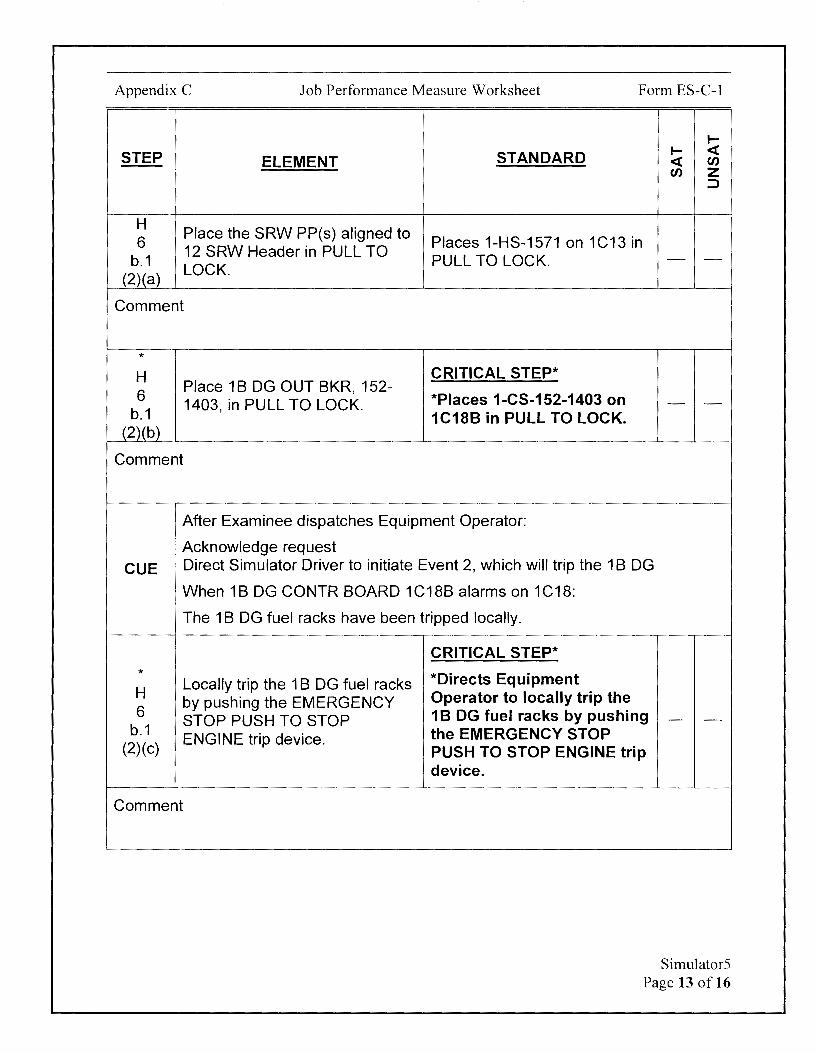
Appendix C Job Performance Measure Worksheet Form ES-C-1
I-
STEP ELEMENT STANDARD I- <( <( Cl) Cl) z
::>
H Place the SRW PP(s) aligned to
6 Places 1-HS-1571 on 1C13 in 12 SRW Header in PULL TO
b.1 PULL TO LOCK. - -
(2)(a) LOCK.
Comment
* H CRITICAL STEP* 6
Place 1 B DG OUT BKR, 152-*Places 1-CS-152-1403 on 1403, in PULL TO LOCK. - -
b.1 1C188 in PULL TO LOCK. (2)(b)
Comment
I After Examinee dispatches Equipment Operator:
Acknowledge request CUE I Direct Simulator Driver to initiate Event 2, which will trip the 1 B DG
; When 18 DG CONTR BOARD 1C18B alarms on 1C18:
The 1 B DG fuel racks have been tripped locally.
CRITICAL STEP* * H
Locally trip the 1 B DG fuel racks *Directs Equipment
by pushing the EMERGENCY Operator to locally trip the 6 1 B DG fuel racks by pushing STOP PUSH TO STOP - -
b.1 ENGINE trip device. the EMERGENCY STOP
(2)(c) PUSH TO STOP ENGINE trip device.
Comment
Simulators Page 13 of 16

Appendix C Job Performance Measure Worksheet Form ES-C-1
I-
STEP STANDARD I- <( ELEMENT <( en
en z ::::,
CUE After Examinee determines communication with the Technical Support Center is required, acknowledge the report.
H Informs the Unit Supervisor or
Consult with the Plant Technical determines consultation with 6
Support Center for guidance on the Technical Support Center b.1 is required - -
(2)(d) system restoration.
Comment
TERMINATING CUE:
This JPM is complete when CSAS flow has been established on 12 CS Header and actions are taken for an idle 12 SRW Header when CAC voiding conditions exist.
The Examiner is expected to end the JPM.
TIME STOP:
Simulators Page 14 of 16
Appendix C Job Performance Measure Worksheet
Verification of Completion
Job Performance Measure Number: Simulators
Examinee:
NRC Examiner:
Date Performed:
Facility Evaluator: -----------------
Number of Attempts: _______________ _
Time to Complete: ________________ _
Follow up Question(s):
Examinee Response:
Result: SATISFACTORY UNSATISFACTORY --- ---
Examiner's Signature and Date:
Form ES-C-1
Simulator5 Page 15 of 16

Appendix C
Initial Conditions:
Job Performance Measure Worksheet
EXAMINEE'S CUE SHEET
1. You are performing the duties of the Unit-1 CRO.
2. 13 SRW Pump is OOS.
3. A Large Break LOCA has occurred.
4. EOP-5, Loss of Coolant Accident, has been implemented.
Initiating Cue:
Form ES-C-1
1. You are to Maintain the Containment Environment per EOP-5 Step Hon Page 19.
Simulator5 Page 16 of 16

Examinee:
Calvert Cliffs Nuclear Power Plant
2018 NRC Initial Licensed Operator Exam
JPM-Simulator6

Appendix C Job Performance Measure Worksheet Form ES-C-1
Facility: Calvert Cliffs 1 & 2
Alternate Path: No
Task Number: 004.007
Task Title: Transfer ESF Buses from SMECO to BG&E Grid
Task Standard:
JPM Number: Simulator6
This JPM is complete when 11 4KV Bus is transferred from SMECO to the BGE Grid.
Time Critical Task: No
KIA Reference: 062A4.01 (3.3/3.1)
Method of Testing: Actual Performance-Simulator
Validation Time: 10 minutes
References and Tools Required:
1. Ol-27E, SMECO Offsite Power System
2. 01-218, 1 B Diesel Generator
Simulator6 Page 2 of 13

Appendix C Job Performance Measure Worksheet Form ES-C-1
JPM Setup Instructions:
1. Reset to IC-34.
2. Trip Unit-1 Reactor.
3. Disable 1A DG by inserting malfunction dg002_02.
4. Disable OC DG by inserting malfunction dg002_01.
5. Initiate Steam Driven AFW on 1 C04.
6. Ensure MSR 2nct Stage Source MO Vs indicate shut at 1-HS-4025 on 1 CO2.
7. Initiate LOOP by opening 1-252-1104 on 1C18.
8. Open 1-252-1201 on 1C18.
9. Open 2-252-2201 on 1C19.
10.0pen 2-252-2104 on 1C19.
11.Tie 1Y09 to 1Y10 using Remote 1SY09 to 1Y10.
12. Shut SMECO Tie Breaker Shut using Remote 252-2301 to CLOSED.
13. Power 11 13KV Bus from SM ECO by shutting 1-252-1105 on 1 C 18.
14. Reset all lockouts by using Remote RESET _86_PLANT to RESET.
15. Match HS flags (to green) on all open breakers on 11 13KV Bus.
16. Match HS flags (to green) on all open breakers on Unit-1 4KV Buses.
17.Close 1-252-1102 on 1C18.
18.Place 1-HS-25on 1C18to0N.
19.Close 1-152-1115 on 1C18 using sync stick.
20. Place 1-HS-25 on 1C18 to NORM.
21. Return sync stick to HOME BASE on 1C19.
22.Shut 2-CS-252-2104 on 1C19.
23. Reset all lockouts by using Remote RESET _86_PLANT to RESET.
24. Place 1A DG Output Breaker, 1-152-1703, in Pull To Lock on 1C18A.
25. Place Abnormal Component tag on 1A DG Output Breaker, 1-152-1703.
26. Place OC DG Breaker, 0-152-0703, in Pull To Lock on 1 C 19C.
27. Hang info tags on OC DG:
• 0-152-0703 on 1C19C
• O-HS-0707 on 1 C 19C
• O-HS-0708 on 1 C 19C
28. Place 11 and 12 Charging Pumps in Pull to Lock on 1 CO?.
Simulator6 Page 3 of 13

Appendix C Job Performance Measure Worksheet
29.Start 12 CCW Pump on 1C13.
30. Ensure SMECO mimic indicates 252-2301 shut on 1C19.
31.ADV position established to maintain RCS temperatures constant.
Form ES-C-1
Simulator6 Page 4 of 13

Appendix C Job Performance Measure Worksheet Form ES-C-1
Directions to the Examinee:
I will explain the initial conditions, which steps to simulate or discuss, and provide initiating cues. When you complete the task successfully, the objective for this job performance measure will be satisfied.
Hand Examinee's Cue Sheet to Examinee at this time.
Initial Conditions:
1. You are performing the duties of the Unit-1 CRO.
2. OC DG was tagged out.
3. A Loss of Offsite Power occurred.
4. 1A DG did not start and is still not available.
5. 1 B DG started and is powering 14 4KV Bus.
6. 1Y09 was tied to 1Y10 with 1Y10 supplying power.
7. 11 13KV Bus was powered by SMECO per Ol-27E.
8. 11 4KV Bus was powered by SMECO per Ol-27E.
9. Offsite Power has been restored and is powering 21 13KV Bus.
Initiating Cue:
1. Initial conditions for Step 6.5 have been verified by the Unit Supervisor.
2. You are to restore 11 4KV Bus to the BG&E Grid on 21 13KV Bus per Ol-27E, Step 6.5.F, starting on Page 39.
3. No other Operators are available to assist.
4. Are there any questions? You may begin.
Simulator6 Page 5 of 13

Appendix C Job Performance Measure Worksheet Form ES-C-1
I-
STEP STANDARD I- <( ELEMENT <( en
en z ::>
TIME START:
CUE After Examinee reviews Cue Sheet, provide the examinee with a copy of 01-27E.
Determines that next step to Locates Ol-27E, Step 6.5.F be performed is Ol-27E Step
6.5.F on Page 39.
i Determines 21 13KV bus is powered from the BG&E Grid based on Cue Sheet
:
6.5 ENSURE 21 13KV Service Bus OR F.1 · energized from BG&E grid. Evaluates electrical mimic on
1C19 and 1C20 and determines 21 13KV bus is
' powered from P-13000-2. i
Comment
CUE If asked, the 1A DG is still not available.
IF 1A Diesel Generator available, THEN PERFORM the
6.5 following: Determines that step is NIA F.2 a. ST ART 1 A Diesel Generator based on Cue Sheet or Cue.
PER Ol-21A, 1A DIESEL GENERATOR.
Comment
6.5 IF 1A Diesel Generator is not
Determines step is applicable available, THEN PERFORM the
F.3 based on Cue Sheet or Cue. following:
- -
- -
- -
- -
Simulator6 Page 6 of 13
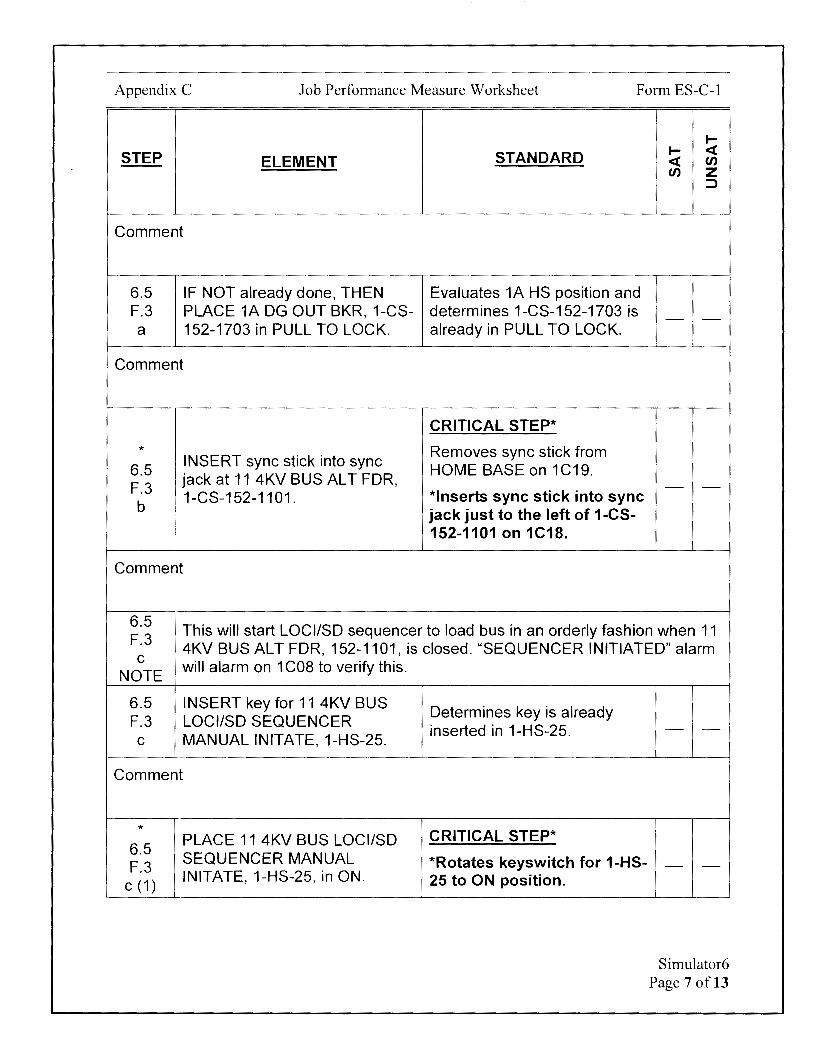
Appendix C Job Performance Measure Worksheet Form ES-C-1
I-
STEP STANDARD I- <( ELEMENT <( en
en z ::>
Comment
6.5 IF NOT already done, THEN Evaluates 1A HS position and F.3 PLACE 1A DG OUT BKR, 1-CS- determines 1-CS-152-1703 is - -a 152-1703 in PULL TO LOCK. already in PULL TO LOCK.
Comment
CRITICAL STEP*
* Removes sync stick from 6.5
INSERT sync stick into sync HOME BASE on 1C19.
F.3 jack at 11 4KV BUS ALT FDR, - -
b 1-CS-152-1101. *Inserts sync stick into sync
! jack just to the left of 1-CS-!
152-1101 on 1C18.
Comment
6.5 This will start LOCI/SD sequencer to load bus in an orderly fashion when 11
F.3 C
4KV BUS ALT FDR, 152-1101, is closed. "SEQUENCER INITIATED" alarm
NOTE will alarm on 1 COS to verify this.
6.5 INSERT key for 11 4KV BUS F.3 LOCI/SD SEQUENCER
C MANUAL INITATE, 1-HS-25.
Comment
* PLACE 11 4KV BUS LOCI/SD
6.5 SEQUENCER MANUAL
F.3 C (1)
INITATE, 1-HS-25, in ON.
Determines key is already inserted in 1-HS-25.
CRITICAL STEP*
*Rotates keyswitch for 1-HS-25 to ON position.
- -
- -
Simulator6 Page 7 of 13

Appendix C Job Performance Measure Worksheet Form ES-C-1
I-
STEP STANDARD I- <t ELEMENT <t en
en z ::::>
Comment
6.5 F.3
The following steps will be a "dead bus" transfer. d
NOTE
Examiner NOTE
Direct Simulator Driver to acknowledge all annunciators during remainder of JPM.
CUE If informed of pending temporary loss of 11 4KV Bus, acknowledge report.
* 6.5 OPEN 11 4KV BUS NORMAL F.3 FDR, 1-CS-152-1115 d
Comment
* 6.5 CLOSE U-4000-21 13KV FDR, F.3 2-CS-252-2102. e
Comment
* 6.5 CLOSE 11 4KV BUS ALT FDR, F.3 1-CS-152-1101. f
Comment
CRITICAL STEP*
*Momentarily places 1-CS-152-1115 to TRIP until breaker 1-152-1115 is open.
CRITICAL STEP*
*Momentarily places 2-CS-252-2102 to CLOSE until breaker 2-252-2102 is shut.
CRITICAL STEP*
*Momentarily places 1-CS-152-1101 to CLOSE until breaker 1-152-1101 is shut.
- -
- -
- -
Simulator6 Page 8 of 13
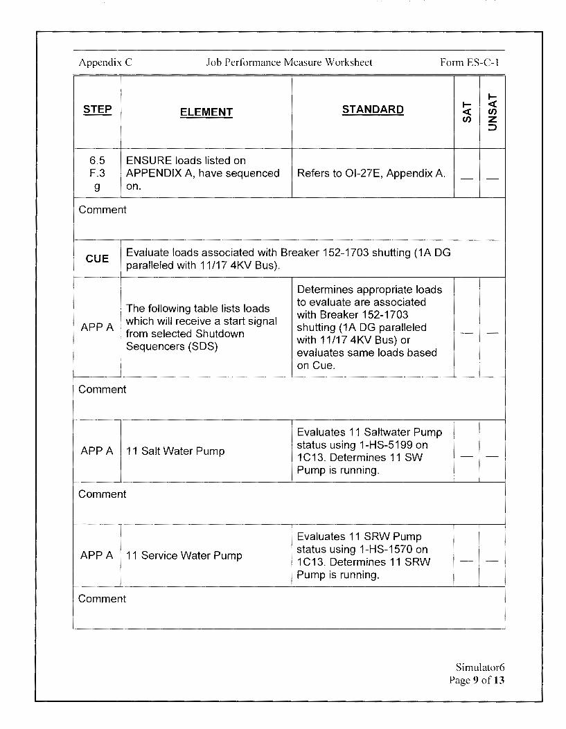
Appendix C Job Performance Measure Worksheet Form ES-C-1
I-
STEP STANDARD I- <( ELEMENT <( en
en z :::,
6.5 ENSURE loads listed on F.3 APPENDIX A, have sequenced Refers to Ol-27E, Appendix A. - -g on.
Comment
CUE Evaluate loads associated with Breaker 152-1703 shutting (1A DG paralleled with 11/17 4KV Bus).
The following table lists loads
APPA which will receive a start signal from selected Shutdown Sequencers (SOS)
I
i
Comment
APPA 11 Salt Water Pump
Comment
APPA 11 Service Water Pump
Comment
Determines appropriate loads to evaluate are associated with Breaker 152-1703 shutting (1A DG paralleled with 11/17 4KV Bus) or evaluates same loads based on Cue.
Evaluates 11 Saltwater Pump status using 1-HS-5199 on 1C13. Determines 11 SW Pump is running.
Evaluates 11 SRW Pump status using 1-HS-1570 on 1C13. Determines 11 SRW Pump is running.
- -
- -
- -
Simulator6 Page 9 of 13

Appendix C Job Performance Measure Worksheet Form ES-C-1
.... STEP STANDARD .... <(
ELEMENT <( en en z
::::,
Evaluates 11 CR HVAC status
APPA 11 Control Room NC using O-HS-5340 on 1 C34. Compressor Determines 11 CR HVAC is - -
running.
Comment
CUE After dispatching Equipment Operator:
11 Switchgear Room Ventilation is in service and running per Ol-22H.
APPA 11 Swgr A/C Compressor
Comment
APPA 11 Instrument Air Compressor
Comment
6.5 ENSURE loads listed on F.3 APPENDIX A, have sequenced g on.
Comment
Directs Equipment Operator to evaluate status of 11 SWGR.
Determines 11 SWGR HVAC - -
is running based on Cue.
Evaluates 11 IA COMPR indications at 1C13 and - -determines 11 IAC is running.
Determines all loads listed on APPENDIX A have sequenced - -on.
Simulator6 Page 10 of 13
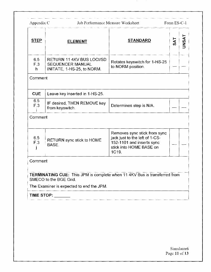
Appendix C Job Performance Measure Worksheet Form ES-C-1
I-
STEP STANDARD I- < ELEMENT < en
en z ::::,
6.5 RETURN 11 4KV BUS LOCI/SD Rotates keyswitch for 1-HS-25
F.3 SEQUENCER MANUAL to NORM position. - -
h INITATE, 1-HS-25, to NORM.
Comment
CUE Leave key inserted in 1-HS-25.
6.5 IF desired, THEN REMOVE key
F.3 Determines step is N/A. from keyswitch. - -
I
Comment
I Removes sync stick from sync 6.5
RETURN sync stick to HOME jack just to the left of 1-CS-
F.3 152-1101 and inserts sync BASE. - -
J stick into HOME BASE on 1C19.
Comment
TERMINATING CUE: This JPM is complete when 11 4KV Bus is transferred from SMECO to the BGE Grid.
The Examiner is expected to end the JPM.
TIME STOP:
Simulator6 Page 11 of 13

Appendix C Job Performance Measure Worksheet
Verification of Completion
Job Performance Measure Number: Simulator6
Examinee:
NRC Examiner:
Date Performed:
Facility Evaluator: ________________ _
Number of Attempts: _______________ _
Time to Complete: -----------------Follow up Question(s):
Examinee Response:
Result: SATISFACTORY UNSATISFACTORY -- --
Examiner's Signature and Date:
Form ES-C-1
Simulator6 Page 12 of 13
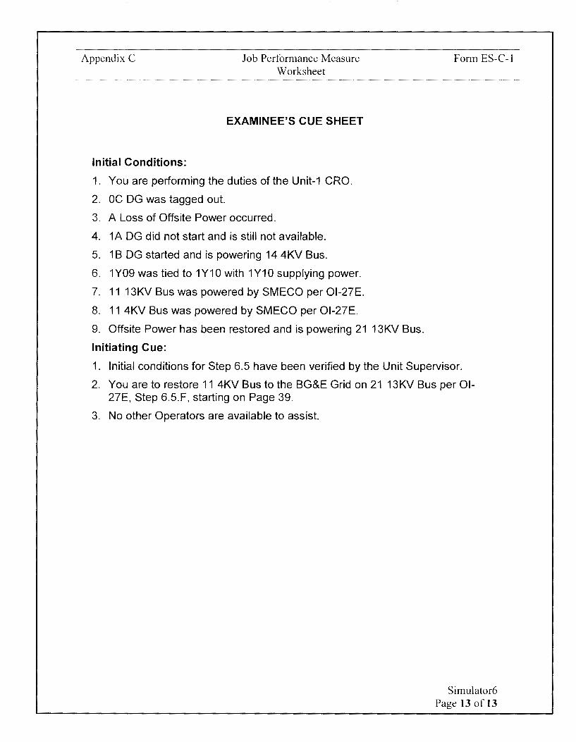
Appendix C
Initial Conditions:
Job Performance Measure Worksheet
EXAMINEE'S CUE SHEET
1. You are performing the duties of the Unit-1 CRO.
2. OC DG was tagged out.
3. A Loss of Offsite Power occurred.
4. 1A DG did not start and is still not available.
5. 1 B DG started and is powering 14 4KV Bus.
6. 1Y09 was tied to 1Y10 with 1Y10 supplying power.
7. 11 13KV Bus was powered by SMECO per Ol-27E.
8. 11 4KV Bus was powered by SMECO per Ol-27E.
9. Offsite Power has been restored and is powering 21 13KV Bus.
Initiating Cue:
Form ES-C-1
1. Initial conditions for Step 6.5 have been verified by the Unit Supervisor.
2. You are to restore 11 4KV Bus to the BG&E Grid on 21 13KV Bus per Ol-27E, Step 6.5.F, starting on Page 39.
3. No other Operators are available to assist.
Simulator6 Page 13 of 13

Calvert Cliffs Nuclear Power Plant
2018 NRC Initial Licensed Operator Exam
JPM-Simulator7
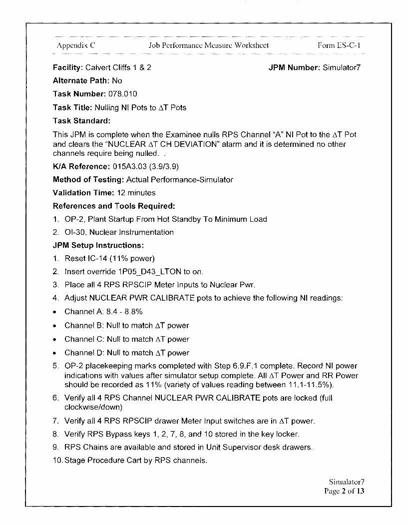
Appendix C Job Performance Measure Worksheet
Facility: Calvert Cliffs 1 & 2
Alternate Path: No
Task Number: 078.010
Task Title: Nulling NI Pots to ~T Pots
Task Standard:
Form ES-C-1
JPM Number: Simulator?
This JPM is complete when the Examinee nulls RPS Channel "A" NI Pot to the~ T Pot and clears the "NUCLEAR ~T CH DEVIATION" alarm and it is determined no other channels require being nulled ..
KIA Reference: 015A3.03 (3.9/3.9)
Method of Testing: Actual Performance-Simulator
Validation Time: 12 minutes
References and Tools Required:
1. OP-2, Plant Startup From Hot Standby To Minimum Load
2. 01-30, Nuclear Instrumentation
JPM Setup Instructions:
1. Reset IC-14 (11 % power)
2. Insert override 1 P05 D43 L TON to on.
3. Place all 4 RPS RPSCIP Meter Inputs to Nuclear Pwr.
4. Adjust NUCLEAR PWR CALIBRATE pots to achieve the following NI readings:
• Channel A: 8.4 - 8.8%
• Channel B: Null to match~ T power
• Channel C: Null to match~ T power
• Channel D: Null to match~ T power
5. OP-2 placekeeping marks completed with Step 6.9.F.1 complete. Record NI power indications with values after simulator setup complete. All ~ T Power and RR Power should be recorded as 11% (variety of values reading between 11.1-11.5%).
6. Verify all 4 RPS Channel NUCLEAR PWR CALIBRATE pots are locked (full clockwise/down)
7. Verify all 4 RPS RPSCIP drawer Meter Input switches are in ~T power.
8. Verify RPS Bypass keys 1, 2, 7, 8, and 10 stored in the key locker.
9. RPS Chains are available and stored in Unit Supervisor desk drawers.
10. Stage Procedure Cart by RPS channels.
Simulator7 Page 2 of 13

Appendix C Job Performance Measure Worksheet Form ES-C-1
Directions to the Examinee:
I will explain the initial conditions, which steps to simulate or discuss, and provide initiating cues. When you complete the task successfully, the objective for this job performance measure will be satisfied.
Hand Examinee's Cue Sheet to Examinee at this time.
Initial Conditions:
1. You are performing the duties of the Unit-1 CRO.
2. A Unit-1 startup is in progress.
3. Power is approximately 11% and holding.
4. 1C05 Annunciator Window D-43, "NUCLEAR flT CH DEVIATION" is in.
Initiating Cue:
1. You are to Null the NI Pots per OP-2, Step 6.9.F.2 on Page 54.
2. Are there any questions? You may begin.
Simulator7 Page 3 of 13

Appendix C Job Performance Measure Worksheet Form ES-C-1
~
STEP STANDARD ~ <( ELEMENT <( en
en z ::,
TIME START:
CUE After Examinee reviews Cue Sheet, provide the examinee with a copy of OP-2-1.
Determines that next step to OP-2 Locates OP-2, Step 6.9.F.2. be performed is OP-2 Step - -
6.9.F.2 on Page 54.
• When nulling NI pots, the possibility exists that the pot may reach its
6.9 hard stop before the NUCLEAR POWER-~ T POWER deviation meter reaches zero.
F.2 NOTE • Tech Spec 3.3.1 requires the Axial Power Distribution Trip and the Loss
of Load Trip to be active when NUCLEAR INSTRUMENT POWER is> 15% RTP.
I I Determines power is between '
10-12% based on Examinee WHEN Reactor power is Cue Sheet and determines 01-between 10 and 12%, THEN 30 must be implemented
6.9 NULL the NI pot for each OR
F.2 1 channel that NI power is reading - -less than Delta-T power PER Evaluates ~ T power
, 01-30, section titled, NULLING indications on 1C15 and NI POTS TO DEL TAT POTS. determines power is between
10-12% and 01-30 must be implemented.
Comment
01-30 Locates 01-30 Step 6.10.
6.10 Initial Conditions
A
Determines that next step to be performed is 01-30 Step 10 on Page 45.
- -
Simulator7 Page 4 of 13

Appendix C Job Performance Measure Worksheet Form ES-C-1
I-
STEP STANDARD I- <( ELEMENT <( en
en z ::,
Evaluates Nuclear PWR-1'.1 T PWR(%) on RPS Calibration &
NI Power is indication less than Indication Panels on 1C15. 6.10
Delta-T Power for the channels A.1 Determines RPS Channel A NI - -
being adjusted. Power is less than Delta-T Power and initial condition is met.
Comment
I
Determines power is between I
10-12% based on Examinee Cue Sheet and determines initial condition is met
i
6.10 I Rated thermal power is less OR A.2 : than or equal to 30%. - -
Evaluates Delta-T power indications on 1C15 and determines power is between 10-12% and initial condition is met.
Comment
6.10 8
6.10 8.1
NOTE
6.7 8.1
CAUTION
Procedure
• Tech Spec 3.3.1 requires the Axial Power Distribution Trip and the Loss of Load Trip to be active when NUCLEAR INSTRUMENT POWER is> 15% RTP.
• Excore NI Power Range Safety Channels are adjusted one entire channel at a time, with the channels selected in any order.
Adjustment of an Excore NI Power Range Safety Channel renders the channel inoperable AND requires entry into Technical Specification Action Statement 3.3.1.
Simulator7 Page 5 of 13
Appendix C Job Performance Measure Worksheet Form ES-C-1
I-
STEP STANDARD I- <( ELEMENT <( en
en z :::>
After Examinee determines Tech Spec 3.3.1 must be entered when
CUE adjusting NI pots:
The Unit Supervisor and the RO have evaluated and implemented all actions required by Tech Spec 3.3.1.
NULL the NI pot for each
6.10 channel that NI power is reading Determines that only Channel
B.1 less than Delta-T power, by A NI power is reading less - -
1 performing Steps a. through i. than Delta-T power.
! for a specific channel.
Comment
BYPASS the following RPS trips for the channel to be adjusted:
* TRIP UNIT BYPASS KEY 6.10 B.1 HI POWER 1
a HI RATE 2 TM/LO PRES 7 LOSS LOAD 8 AXIAL PWR 10
Comment
CRITICAL STEP*
Obtains RPS Bypass keys 1, 2, 7, 8, and 10 from key cabinet.
At RPS Channel A on 1C15, inserts bypass key and then rotates key until bypass light illuminates for the following Trip Units:
Trip Unit 1
Trip Unit 2
Trip Unit 7
Trip Unit 8
Trip Unit 10
- -
Simulator7 Page 6 of 13
Appendix C Job Performance Measure Worksheet Form ES-C-1
I-
STEP STANDARD I- <( ELEMENT <( en
en z ::J
After Examinee requests an independent verification that correct RPS
CUE Channel "A" Trip Units 1, 2, 7, 8 & 10 are bypassed:
The independent verification has been completed Step 6.10.B.1.b is complete
6.10 INDEPENDENTLY VERIFY that Requests an independent
B.1 RPS Trip Units 1, 2, 7, 8 & 10 verification that the correct RPS Trip Units have been - -
b are bypassed. bypassed.
Comment
CRITICAL STEP* * *Places METER INPUT
6.10 PLACE the DVM METER INPUT switch on 1C15 RPS B.1 switch in NUCLEAR PWR. Channel A Calibration & - -
C Indication Panel to NUCLEAR PWR.
Comment
• Counterclockwise rotation raises the reading . 6.10 B.1 • When nulling NI pots, the possibility exists that the pot may reach its
d hard stop before the NUCLEAR POWER-Li T POWER deviation meter
NOTE reaches zero. During a plant startup, this is acceptable as long as the NUCLEAR LiT CH DEVIATION alarm is clear.
6.10 Potentiometer adjustments must be stopped immediately if 1 (2)C05 B.1 annunciator "POWER LEVEL HIGH CHANNEL PRE-TRIP" alarms while d adjusting a potentiometer.
CAUTION
Examiner NOTE
Direct Simulator Driver to remove 1 C05 D-43 Override when the NUCLEAR PWR CALIBRATE potentiometer is adjusted and Nuclear PWR-LiT PWR(o/o) on Channel A RPS Calibration & Indication Panel on 1C15 is -(-)2%.
Simulator7 Page 7 of 13
Appendix C Job Performance Measure Worksheet Form ES-C-1
STEP ELEMENT
UNLOCK AND slowly ADJUST * the NUCLEAR PWR
6.10 CALIBRATE potentiometer B.1 (FIGURE 1 - Item D) to zero the d NUCLEAR POWER DEL TA-T
POWER deviation meter.
Comment
1 IF 1 (2)C05 annunciator
6.10 ' "POWER LEVEL HIGH
B.1 CHANNEL PRE-TRIP" alarms
d while potentiometer is being adjusted, THEN STOP
(1) adjustment AND ENSURE test switch alignment is correct.
Comment
IF 1 (2)C05 annunciator "POWER LEVEL HIGH
6.10 CHANNEL PRE-TRIP" alarmed B.1 AND test switch alignment is d correct, THEN REQUEST IM to
(2) check HIGH POWER Trip Unit pre-trip AND trip setpoints on that channel.
Comment
STANDARD
CRITICAL STEP*
*Unlocks NUCLEAR PWR CALIBRATE potentiometer and adjusts NUCLEAR PWR CALIBRATE potentiometer until Nuclear PWR-~ T PWR(%) on Channel A RPS Calibration & Indication Panel on 1C15 reads - 0.
Evaluates annunciator POWER LEVEL HIGH CHANNEL PRE-TRIP alarm on 1 C05 and determines step is N/A.
Evaluates annunciator POWER LEVEL HIGH CHANNEL PRE-TRIP alarm on 1 C05 and determines step is NIA.
I-I- <( <( en en z
:)
- -
- -
- -
Simulator7 Page 8 of 13

Appendix C Job Performance Measure Worksheet Form ES C I - -
STEP ELEMENT
6.10 LOCK the locking device on the B.1 NUCLEAR PWR CALIBRATE e potentiometer.
Comment
6.10 IF tripped, THEN RESET VOPT
B.1 AND RPS Trip Units 1, 7 and 1 O
f AND associated Control Room annunciators.
Comment
* 6.10
REMOVE the Trip Bypass Keys
B.1 from RPS Trip Units 1, 2, 7, 8 & 10.
g
Comment
STANDARD
Locks the NUCLEAR PWR CALIBRATE potentiometer by rotating lock full clockwise/down.
Evaluates RPS Trip Unit status on Channel A on 1 C 15 and determines step is N/A as no trip units are in a tripped condition.
CRITICAL STEP
* At RPS Channel A on 1C15, rotates bypass key, verifies the bypass light goes out, and then removes key for the following Trip Units:
Trip Unit 1
Trip Unit 2
Trip Unit 7
Trip Unit 8
Trip Unit 10
I-I- <( <( en en z
::J
- -
- -
- -
Simulator7 Page 9 of 13

Appendix C Job Performance Measure Worksheet Form ES-C-1
I-
STEP STANDARD I- ~ ELEMENT ~ en
en z ::J
After Examinee requests an independent verification that the bypass keys have been correctly removed from RPS Channel "A" Trip Units 1, 2, 7, 8 &
CUE 10:
The independent verification has been completed Step 6.10.B.1.h is complete
Requests an independent 6.10 INDEPENDENTLY VERIFY that verification that bypass keys B.1 Trip Bypass Keys are removed have been correctly removed h from Trip Units 1, 2, 7, 8 & 10. from RPS Channel "A" Trip
Un its 1 , 2, 7, 8 & 10.
Comment
6.10 Places METER INPUT switch
PLACE the DVM METER INPUT on 1C15 RPS Channel A B.1
switch in 6 T PWR. Calibration & Indication Panel I
to 6T PWR.
Comment
Evaluates Nuclear PWR-6 T PWR(%) on Channel B, C,
6.10 REPEAT Steps a. through i. for and D RPS Calibration & B.1 the next NI channel until all Indication Panels on 1C15.
J desired channels are nulled. Determines process is NOT ' required for RPS Channels B,
C, or D.
Comment
- -
- -
- -
Simulator7 Page 10 of 13
Appendix C Job Performance Measure Worksheet Form ES-C-1
I-
STEP STANDARD I- <( ELEMENT <( en
en z =>
Evaluates green POWER light
6.10 CHECK the POWER ON LED is for RPS Channels A, 8, C, and illuminated for ALL four D. Determines that POWER
8.2 - -channels. ON LED is lit for all four
channels.
Comment
6.10 IF POWER ON LED is NOT
8.2 illuminated, THEN INITIATE an Determines step is NIA. 1st - -
bullet i IR to investigate and repair. i
Comment
TERMINATING CUE:
This JPM is complete when the Examinee nulls RPS Channel "A" NI Pot to the 11 T Pot and clears the "NUCLEAR 11 T CH DEVIATION" alarm and it is determined no other channels require being nulled.
The Examiner is expected to end the JPM.
TIME STOP:
Simulator7 Page 11 of 13
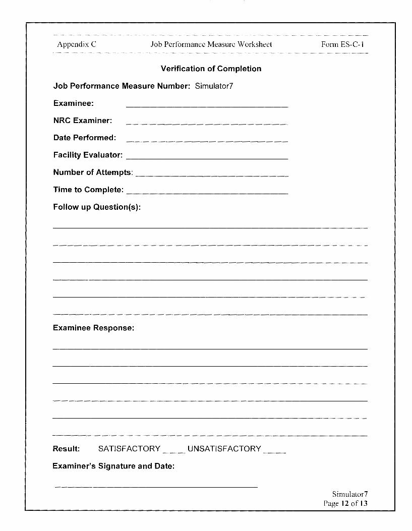
Appendix C Job Performance Measure Worksheet
Verification of Completion
Job Performance Measure Number: Simulator?
Examinee:
NRC Examiner:
Date Performed:
Facility Evaluator: -----------------Number of Attempts: ----------------Time to Complete: -----------------Follow up Question(s):
Examinee Response:
Result: SATISFACTORY UNSATISFACTORY -- --
Examiner's Signature and Date:
Form ES-C-1
Simulator7 Page 12 of 13
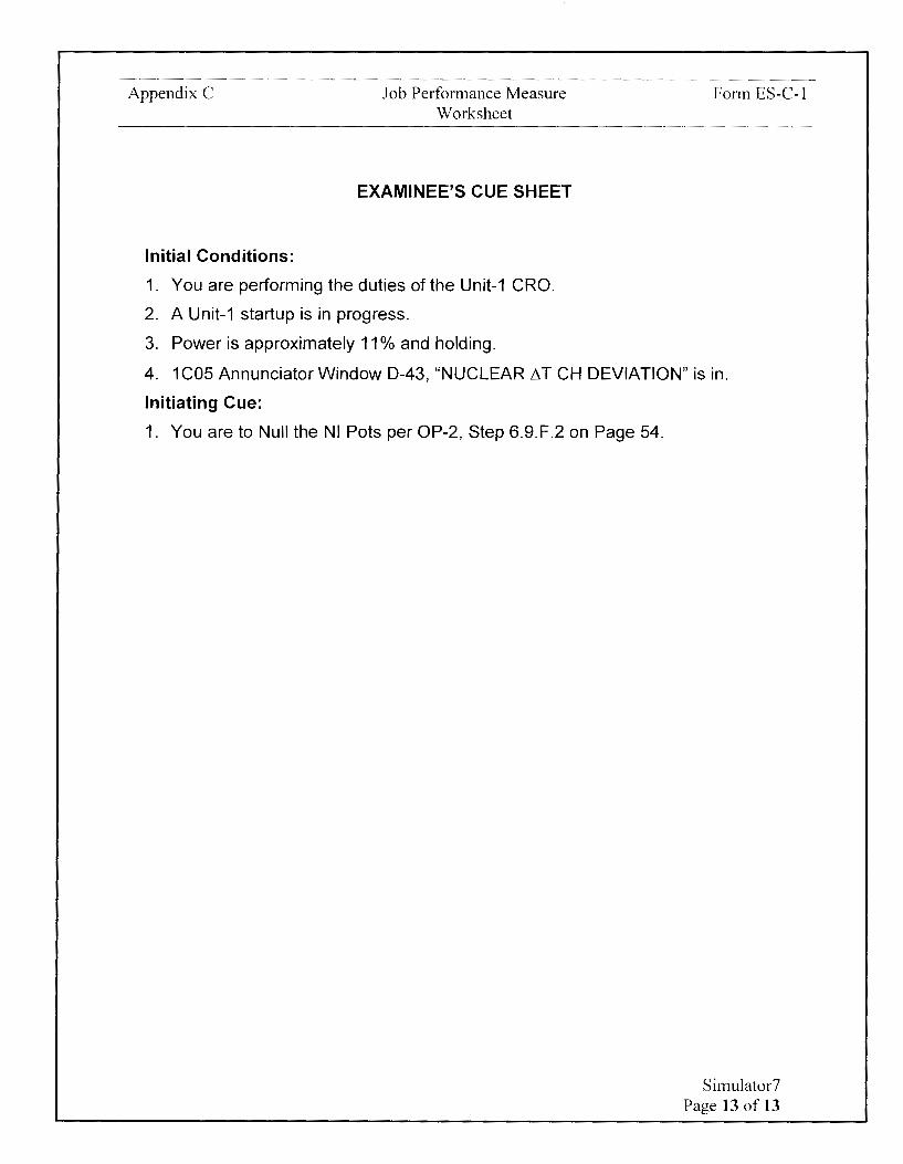
Appendix C
Initial Conditions:
Job Performance Measure Worksheet
EXAMINEE'S CUE SHEET
1. You are performing the duties of the Unit-1 CRO.
2. A Unit-1 startup is in progress.
3. Power is approximately 11 % and holding.
Form ES-C-1
4. 1C05 Annunciator Window D-43, "NUCLEAR L'lT CH DEVIATION" is in.
Initiating Cue:
1. You are to Null the NI Pots per OP-2, Step 6.9.F.2 on Page 54.
Simulator7 Page 13 of 13
Calvert Cliffs Nuclear Power Plant
2018 NRC Initial Licensed Operator Exam
JPM-Simulator8

Appendix C Job Performance Measure Worksheet Form ES-C-1
Facility: Calvert Cliffs 1 & 2
Alternate Path: Yes
Task Number: 202.055
Task Title: Respond to loss of Refueling Pool level
Task Standard:
JPM Number: Simulators
This JPM is complete when SOC flow has been lowered, a lowering RFP level is identified, the SFP is isolated from the RFP, and actions to contain airborne activity are completed from the Control Room.
K/A Reference: 029A 1.02 (3.4/3.4)
Method of Testing: Actual Performance-Simulator
Validation Time: 14 minutes
References and Tools Required:
1. 01-38. Shutdown Cooling
2. AOP-6E, Loss of Unit-1 Refueling Pool Level
JPM Setup Instructions:
1. Reset to IC-4.
2. Verify the following keys are inserted: 25-28, 25, 35, 37-39, 47and 48.
3. Fill RFP to 67' using Insight Table Refueling Pool Level and cells 701, 707, and 708.
4. Verify SOC in service with 11 LPSI Pump running at 3000 GPM.
5. Verify that Sl-657-CV position will allow SOC flow to be lowered< 1500 GPM (i.e. adjusted such that with Sl-306-CV full shut, SOC flow is < 1500 GPM.)
6. Verify tags on 1 CO? indicate SOC purification is secured (1-Sl-464/465/475-Shut).
7. Verify 1-HS-2520 in BYPASS on 1C07.
8. Verify 11 Main Exhaust Fan (1-HS-5412) is running on Unit-1 on 1C34.
9. Verify 21 Main Exhaust Fan (2-HS-5412) is running on Unit-2 on 1 C34.
10. Verify 11 AUX BLDG & WP EXH FAN (1-HS-5410) is running on Unit-1 on 1 C34.
11. Verify 21 AUX BLDG & WP EXH FAN (2-HS-5410) is running on Unit-2 on 1 C34.
12. Verify 11 SFP EXH FAN (O-HS-5419) is running on 1 C34.
13. Verify 11 AUX BLDG & WP SUPP FAN (1-HS-5422) is running on 1 C34.
14.Start 12 AUX BLDG & WP SUPP FAN (1-HS-5423) on 1C34.
15. Open AUX BLDG & WP XCONN 2-HVAC-5440 (2-HS-5440) on 1 C34.
16.Stop 21 AUX BLDG & WP SUPP FAN (2-HS-5422) on 1C34.
Simulator 8 Page 2 of 17

Appendix C Job Performance Measure Worksheet Form ES-C-1
17.Verify SFP EXH FILT handswitch, O-HS-5416, in the FILTER position at 1C34.
18. Cover 1 C05 and 1 C06 PAMS screens with paper stating Reactor Vessel Head removed.
19. Malfunctions:
a. rcs002 to 10000.0 on Event 1
20. Overrides:
a. P1C10 J21 LTON to On on Event 1 - -
b. P1C08 1LIA4144 MT from Oto 2.00000 in 600 on event 1 - -c. P 1 C09 1 LIA4145 MT from O to 2 .00000 in 600 on event 1 - -
21. Ensure Schedule in RUN.
Simulator 8 Page 3 of 17

Appendix C Job Performance Measure Worksheet Form ES-C-1
Directions to the Examinee:
I will explain the initial conditions, which steps to simulate or discuss, and provide initiating cues. When you complete the task successfully, the objective for this job performance measure will be satisfied.
Hand Examinee's Cue Sheet to Examinee at this time.
Initial Conditions:
1. You are performing the duties of the Unit-1 CRO.
2. SRW is running in a normal lineup for testing support.
3. Unit-1 is in Mode 6 with refueling activities in progress.
4. Shutdown Cooling (SOC) is in service per Ol-3B Section 6.1.1 with 11 LPSI Pump in service
5. SOC purification is not in service.
6. RCS boron is 2529 PPM and steady.
7. RCS temperature band is 100-120°F.
8. The Fuel Handling Supervisor has requested that SOC flow be lowered to 2000 GPM due to fuel moves near the 12 Hot Leg.
Initiating Cue:
1. You are to lower SOC flow from 3000 to between 1500-1525 GPM per Ol-3B Step 6.8.4 on Page 109.
2. Are there any questions? You may begin.
Simulator 8 Page 4 of 17

Appendix C Job Performance Measure Worksheet Form ES-C-1
I-
STEP STANDARD I- <( ELEMENT <( en
en z ::>
TIME START:
CUE After Examinee reviews Cue Sheet, provide the examinee with a copy of 01-38-1.
Determines that next step to 01-38 Locates 01-38, Step 6.8.4. be performed is 01-38, Step
6.8.4.
6.8.4 Initial Conditions
A
6.8.4 SOC in operation PER Section Determines that Initial condition is met per Examinee
A.1 6.1.1, Normal Initiation of SOC. Cue Sheet.
Comment
CUE If asked, there are no dilution activities in progress.
6.8.4 / NO reduction in RCS boron Determines that Initial
A.2 concentration is in progress. condition is met per Examinee Cue Sheet.
Comment
6.8.4 Procedure
8
6.8.4 IF desired THEN LOWER SOC Determines step is applicable based on Examinee Cue
8.1 FLOW to 1500 GPM as follows: Sheet.
Comment
- -
- -
- -
- -
Simulator 8 Page 5 of17
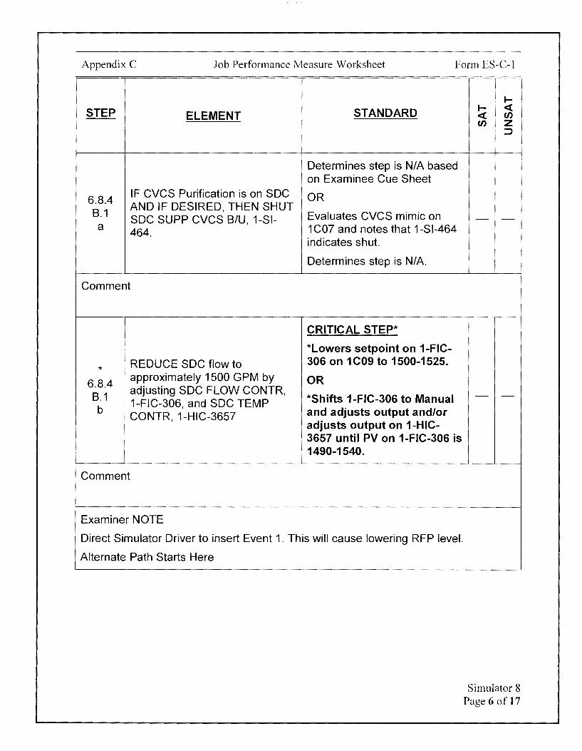
Appendix C Job Performance Measure Worksheet Form ES-C-1
STEP ELEMENT STANDARD
Determines step is NIA based on Examinee Cue Sheet
6.8.4 IF CVCS Purification is on SOC OR
8.1 AND IF DESIRED, THEN SHUT
Evaluates CVCS mimic on soc SUPP eves 8/U, 1-SI-a
464. 1 CO? and notes that 1-Sl-464 indicates shut.
Determines step is NIA
Comment
CRITICAL STEP*
*Lowers setpoint on 1-FIC-REDUCE SOC flow to 306 on 1 C09 to 1500-1525.
* 6.8.4
1 approximately 1500 GPM by OR
8.1 I adjusting SOC FLOW CONTR, *Shifts 1-FIC-306 to Manual 1-FIC-306, and SOC TEMP
b 1 CONTR, 1-HIC-3657 and adjusts output and/or adjusts output on 1-HIC-3657 until PV on 1-FIC-306 is 1490-1540.
Comment
Examiner NOTE
Direct Simulator Driver to insert Event 1. This will cause lowering RFP level.
Alternate Path Starts Here
I-I- <( <( (J) (J) z
::::>
- -
- -
Simulator 8 Page 6 of 17
Appendix C Job Performance Measure Worksheet Form ES-C-1
I-
STEP STANDARD I- <( ELEMENT <( en
en z ::J
After Examinee notes unexpected alarms, direct the Examinee to monitor the Refueling Cart.
Once the Examinee notes that RFP level is lowering:
• A large leak from the North Refueling Cavity has been identified by the CUE Containment Coordinator
• The RO and an extra RO will implement AOP-3B .
• Isolate the Spent Fuel Pool from the Refueling Pool per AOP-6E, Step IV. B
• Provide Examinee with copy of AOP-6E.
I Notes unexpected CNTMT
I
NORMAL SUMP LVL HI alarm I
on 1C10.
Monitors the parameters on I Determines unexpected alarm the Refueling Cart and , received. determines that RFP level is - -I lowering.
Determines that AOP-6E must be implemented based on the Cue.
Comment
AOP-6E Locates AOP-6E, Step IV.B.
B ISOLATE THE SFP FROM THE RFP.
Determines that next step to be performed is AOP-6E, Step IV.Bon Page 9.
- -
Simulator 8 Page 7 of 17
Appendix C Job Performance Measure Worksheet Form ES-C-1
.... STEP STANDARD .... <C
ELEMENT <C en en z
::>
After Examinee requests Transfer Carriage status:
CUE The RCRO reports that the Fuel Transfer Carriage is in the Spent Fuel Pool and the carriage is currently in the Horizontal position.
IF the Transfer Carriage is in the
B.1 RFP, THEN transfer it to the Determines step is N/A based SFP PER Ol-25E, FUEL on Cue. - -
TRANFER SYSTEM.
Comment
B Shutting the Transfer Tube Gate Valve, O-SFP-1, may be delayed if
2 NOTE
additional time is needed to place a Fuel Assembly in a safe location.
B WHEN the Transfer Carriage is
2 I in the SFP, THEN perform the following actions:
Comment
B Ensure that it is in the horizontal 2.a position.
Comment
Determines following steps can be performed based on Cue.
Determines that Transfer Carriage is in the horizontal position based on Cue.
- -
- -
Simulator 8 Page 8 of 17

Appendix C Job Performance Measure Worksheet Form ES-C-1
I-
STEP STANDARD I- <( ELEMENT <( en
en z ::::>
CRITICAL STEP*
Stop 11 and 12 SFP CLG PPS: *Places the following
* handswitches momentarily B • O-HS-1994 to TRIP or to PULL TO LOCK
2.b • O-HS-1995 on 1C13:
• O-HS-1994 • O-HS-1995
Comment
CUE \ After Examinee dispatches Equipment Operator:
i O-SFP-1 is shut.
* CRITICAL STEP* B
Shut the transfer Tube Gate Valve, O-SFP-1. *Directs an Equipment
2.c Operator to shut O-SFP-1.
Comment
CUE After Examinee dispatches Equipment Operator:
O-SFP-103 and O-SFP-107 are shut.
Shut the SPF Pump Discharge CRITICAL STEP* * Valves: B *Directs an Equipment
2.d • (11 SFP Pump) O-SFP-103 Operator to shut O-SFP-103 • (12 SFP Pump) O-SFP-107 and O-SFP-107.
Comment
- -
- -
- -
Simulator 8 Page 9 of 17

Appendix C Job Performance Measure Worksheet Form ES-C-1
I-
STEP STANDARD I- <( ELEMENT <( en
en z ::::>
Inform Examinee that AOP-6E Step IV. C is being performed by the Unit-2
CUE Unit Supervisor.
Perform AOP-6E Step IV. D, Contain the Airborne Activity.
Determines that next step to AOP-6E Locates AOP-6E, Step IV.D. be performed is AOP-6E, Step - -
IV.Don Page 11.
D Isolate Containment Purge:
1
CRITICAL STEP*
* *Places the following
D Stop 11 CNTMT PURGE SUPP handswitches in STOP on and EXH F ANs. 1C34: - -
1.a • 1-HS-5290
I
I • 1-HS-5289 I
Comment
Close 11 CNTMT PURGE * SUPP and EXH valves: D
1.b • 1(2)-HS-1410
• 1(2)-HS-1412
Comment
CRITICAL STEP*
*Places the following handswitches in CLOSE on 1C10:
• 1-HS-1410 • 1-HS-1412
- -
Simulator 8 Page 10 of 17

Appendix C Job Performance Measure Worksheet Form ES-C-1
I-
STEP STANDARD I- <( ELEMENT <( en
en z ::J
CRITICAL STEP* Start all available IODINE FIL T *Momentarily places
* FANs: following handswitches in D • 11 FAN 1 (2)-HS-5293 START on 1C10: - -2 • 12 FAN 1 (2)-HS-5295 1-HS-5293 •
• 13 FAN 1 (2)-HS-5297 • 1-HS-5295 • 1-HS-5297
Comment
D Log the start time of the Iodine Logs start time for each fan in 3 Filter Fans. AOP-6E. - -
Comment
D I Ensure the minimum flow requirement (1700 GPM) for the SRW pumps is 4 I · t · d
CAUTION i main ame .
CUE If asked, SRW is not in a reduced load lineup.
I
IF the SRW system is aligned D · for reduced load operation, 4 THEN start a second SRW
pump.
Comment
Evaluates SRW Pump indications on 1C13 or Cue.
Determines 2 SRW Pumps are - -
running and step is NIA.
Simulator 8 Page 11 of 17
Appendix C Job Performance Measure Worksheet
STEP ELEMENT STANDARD
Open the CNTMT CLR EMER CRITICAL STEP*
OUT valves on ALL available * Places following Containment Air Coolers handswitches in OPEN on
* (CACs): 1C09: D 5 • (11 CAC) 1-HS-1582
(12 CAC) 1-HS-1585 • 1-HS-1582 • (13 CAC) 1-HS-1590 • 1-HS-1585 • (14 CAC) 1-HS-1593 • 1-HS-1590 •
• 1-HS-1593
Comment
Verifies SRW flow is greater than zero on flow indications on 1 C09 below or using the
D Verify SRW flow through the Plant Computer: available Containment Air
6 • 1-Fl-1581 Coolers. • 1-Fl-1584
I 1-Fl-1589
I • • 1-Fl-1592
'
Comment
i CRITICAL STEP* i
. Start ALL available CNTMT AIR *Momentarily places 1
CLRs in HIGH speed: following handswitches in * D • (11 CAC) 1-HS-5299 HIGH on 1 C09:
7 • (12 CAC) 1-HS-5300 • 1-HS-5299 • (13 CAC) 1-HS-5301 • 1-HS-5300 • (14 CAC) 1-HS-5302 • 1-HS-5301
• 1-HS-5302
Comment
Form ES-C-1
I-I- <( <( en en z
::J
- -
- -
- -
Simulator 8 Page 12 of 17

Appendix C Job Performance Measure Worksheet Form ES-C-1
I-
STEP ELEMENT STANDARD I- <( <( en en z
::J
D Maintain a negative pressure in 8 the Aux Building:
Check that ONE of the MAIN Evaluates Main Exhaust Fans
EXH FANs is running on EACH at 1C34.
D unit: Determines that 11 Main 8.a
11(21) Fan 1(2)-HS-5412 Exhaust Fan is running on - -
• • 12(22) Fan 1 (2)-HS-5413
Unit-1 and 21 Main Exhaust Fan is running on Unit-2.
Comment
Evaluates Aux Building
Check that ONE of the AUX Ventilation Fans at 1 C34.
BLDG & WP EXH FANs is Determines that 11 AUX D running on EACH unit: BLDG & WP EXH FAN (1-HS-
8.b 11 (21) Fan 1(2)-HS-5410
5410) is running on Unit-1. - -
' . I
! • 12(22) Fan 1 (2)-HS-5411 Determines that 21 AUX BLDG & WP EXH FAN (2-HS-5410) is running on Unit-2.
I
Comment
CUE After Examinee dispatches Equipment Operator:
The 69 foot to 45 foot rolling door is shut.
D Verify shut the Cask Unloading
9 Hatch (69 foot to 45 foot rolling door).
Comment
Directs Equipment Operator to verify the Cask Unloading Hatch (69 foot to 45 foot rolling - -
door) is shut.
Simulator 8 Page 13 of 17
Appendix C Job Performance Measure Worksheet Form ES-C-1
STEP ELEMENT
D Maintain a negative pressure in
10 the Fuel Handling Area by performing the following:
Check that ONE of the SFP EXH FANs is running:
D • 11 SFP EXH FAN 0-HS-10.a 5419
• 12 SFP EXH FAN 0-HS-5420
Comment
Check that TWO AUX BLDG & WP SUPPLY FANs are running:
D • 11 (21) AUX BLDG & WP
10.b ' SUPP FAN 1-HS-5422 (2-HS-5422)
• 12 AUX BLDG & WP SUPP I FAN 1-HS-5423
i Comment
Verify the SFP EXH FIL T D 11
handswitch, O-HS-5416, in the FILTER position.
Comment
I-
STANDARD I- <( <( en en z
=>
Evaluates SFP Ventilation Fans at 1 C34.
Determines that 11 SFP EXH - -
FAN (O-HS-5419) is running.
Evaluates Aux Building Ventilation Fans at 1 C34.
Determines that 11 AUX BLDG & WP SUPP FAN (1-HS-5422) is running. - -
Determines 12 AUX BLDG & WP SUPP FAN (1-HS-5423) is running.
Evaluates SFP Ventilation on 1C34.
Determines SFP EXH FIL T handswitch (O-HS-5416) is in the FILTER position.
- -
Simulator 8 Page 14 of 17

Appendix C Job Performance Measure Worksheet Form ES-C-1
TERMINATING CUE:
This JPM is complete when SOC flow has been lowered, a lowering RFP level is identified, the SFP is isolated from the RFP, and actions to contain airborne activity are completed from the Control Room.
The Examiner is expected to end the JPM.
TIME STOP: ---
Simulator 8 Page15of17

Appendix C Job Performance Measure Worksheet
Verification of Completion
Job Performance Measure Number: Simulators
Examinee:
NRC Examiner:
Date Performed:
Facility Evaluator: ________________ _
Number of Attempts: _______________ _
Time to Complete: ________________ _
Follow up Question(s):
Examinee Response:
Result: SATISFACTORY UNSATISFACTORY -- --
Examiner's Signature and Date:
Form ES-C-1
Simulator 8 Page 16 of 17
Appendix C
Initial Conditions:
Job Performance Measure Worksheet
EXAMINEE'S CUE SHEET
1. You are performing the duties of the Unit-1 CRO.
2. SRW is running in a normal lineup for testing support.
3. Unit-1 is in Mode 6 with refueling activities in progress.
Form ES-C-1
4. Shutdown Cooling (SOC) is in service per Ol-3B Section 6.1.1 with 11 LPSI Pump in service
5. SOC purification is not in service.
6. RCS boron is 2529 PPM and steady.
7. RCS temperature band is 100-120°F.
8. The Fuel Handling Supervisor has requested that SOC flow be lowered to 1500 GPM due to fuel moves near the 12 Hot Leg.
Initiating Cue:
1. You are to lower SOC flow from 3000 to between 1500-1525 GPM per Ol-3B Step 6.8.4 on Page 109.
Simulator 8 Page 17 of 17
Examinee:
Calvert Cliffs Nuclear Power Plant
2018 NRC Initial Licensed Operator Exam
JPM-Plant1

Appendix C Job Performance Measure Worksheet Form ES-C-1
Facility: Calvert Cliffs 1 & 2
Alternate Path: No
Task Number: 202.123
Task Title: Secure the MG Sets
Task Standard:
JPM Number: Plant1
This JPM is complete when the MG sets have been shutdown locally, the Reactor is verified shutdown, and SG Blowdown/RCP Bleedoff/Letdown/RCS Sampling are all isolated to conserve SG and RCS inventory.
Time Critical Task: No
KIA Reference: 001A1 .06 (4.1/4.4)
Method of Testing: Simulated-Plant
Validation Time: 12 minutes
References and Tools Required:
1. AOP-98-2, Safe Shutdown Due to a Severe Cable Spreading Room Fire
2. Pictures of cabinet 2-NX-001A 1 internals
JPM Setup Instructions:
1. AOP-98-2, Safe Shutdown Due to a Severe Cable Spreading Room Fire, printed single sided, in a procedure binder.
2. Pictures available for examinee of cabinet 2-NX-001 A 1 internals, per attached.
Plant I Page 2 of 15

Appendix C Job Performance Measure Worksheet Form ES-C-1
Plant I Page 3 of 15

Appendix C Job Performance Measure Worksheet Form ES-C-1
Directions to the Examinee:
I will explain the initial conditions, which steps to simulate or discuss, and provide initiating cues. When you complete the task successfully, the objective for this job performance measure will be satisfied.
Hand Examinee's Cue Sheet to Examinee at this time.
Initial Conditions:
1. You are performing the duties of the Unit-2 CRO.
2. A severe fire has started in the Unit-2 Cable Spreading Room.
3. AOP-98-2, Safe Shutdown Due to a Severe Cable Spreading Room Fire, has been implemented.
4. All actions in the Unit-2 Control Room have been attempted.
5. Unit-2 personnel have evacuated the Control Room.
6. You have obtained your necessary key ring and equipment at the Safe Shutdown Panel in the Unit-2 45' SWGR Room per Step IV.H.
Initiating Cue:
1. The Unit Supervisor directs you to respond to the Unit-2 Cable Spreading Room fire using AOP-98-2, Safe Shutdown Due to a Severe Cable Spreading Room Fire.
2. Starting in the Unit-2 45' SWGR Room, you are to commence with Step IV.I, Shutdown 21 and 22 GEOM MG Sets, on page 10.
3. You are to perform all CRO position-specific steps.
4. No other Operators are available to assist.
5. All component actions will be simulated.
6. Are there any questions? You may begin.
Plant I Page 4 of 15
Appendix C Job Performance Measure Worksheet Form ES-C-1
t-
STEP STANDARD t- <( ELEMENT <( en
en z :::,
TIME START:
CUE After Examinee reviews Cue Sheet, provide the examinee with a copy of AOP-98-2.
Locates AOP-98-2, Step IV.I- Determines that next step to SHUTDOWN21AND22CEDM be performed is IV.I, to MG SETS shutdown 21 and 22 MG Sets
IV.I On GEOM MG Set Control Locates panel 2C87 in U-2 45' 1 Panel: Switchgear Room
Comment
Initially, the Local LOAD ON light is lit.
CUE After Local LOAD OFF Pushbutton is depressed:
Local LOAD ON light goes out Local/22 MG Generator Amps read zero.
I I CRITICAL STEP* *
IV.I Depress Local LOAD OFF
*Depresses Local LOAD ! Pushbutton. 1.a
i OFF button on 2C87
Comment
- -
- -
- -
Plant I Page S of 15
Appendix C Job Performance Measure Worksheet Form ES-C-1
I-
STEP STANDARD I- <( ELEMENT <( CJ')
CJ') z :)
Initially, the Remote LOAD ON light is lit.
CUE After Remote LOAD OFF Pushbutton is depressed:
Remote LOAD ON light goes out. Remote/21 MG Generator Amps read zero.
* CRITICAL STEP* IV.I
Depress Remote LOAD OFF *Depresses Remote LOAD Pushbutton. - -
1.b OFF button on 2C87
Comment
Initially, the Local MOTOR ON light is lit.
CUE After Local MOTOR OFF Pushbutton is depressed for several seconds:
Local MOTOR ON light goes out Local/22 MG Generator Volts and Exciter Field Amps ramp to zero Noise level from 22 MG starts to lower.
CRITICAL STEP* I
* 1 Depress and hold Local MOTOR *Depresses and holds Local IV.I OFF Pushbutton until MOTOR MOTOR OFF button on 2C87 1.c j ON light deenergizes. until Local MOTOR ON light
' goes out I
Comment
- -
Plant I Page 6 of 15
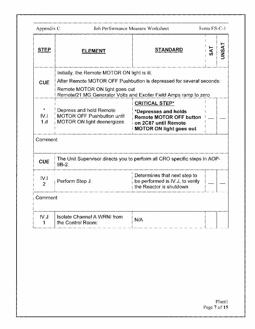
Appendix C Job Performance Measure Worksheet Form ES-C-1
I-
STEP STANDARD I- ~ ELEMENT ~ en
en z ::>
Initially, the Remote MOTOR ON light is lit.
CUE After Remote MOTOR OFF Pushbutton is depressed for several seconds:
Remote MOTOR ON light goes out Remote/21 MG Generator Volts and Exciter Field Amps ramp to zero
CRITICAL STEP* * Depress and hold Remote *Depresses and holds
IV.I MOTOR OFF Pushbutton until Remote MOTOR OFF button - -1.d MOTOR ON light deenergizes. on 2C87 until Remote
MOTOR ON light goes out
Comment
CUE The Unit Supervisor directs you to perform all CRO specific steps in AOP-98-2.
IV.I 2 I Perform Step J.
' Comment
IV.J Isolate Channel A WRNI from 1 the Control Room:
Determines that next step to be performed is IV.J, to verify the Reactor is shutdown
NIA
- -
Plant I Page 7 of 15

Appendix C Job Performance Measure Worksheet Form ES-C-1
I-
STEP STANDARD I- <( ELEMENT <( en
en z :)
After locating and simulating how to open cabinet 2-NX-001A 1:
CUE The cabinet is open. Provide pictures of cabinet 2-NX-001A 1 internals. Voltage in the cabinet is< 50 volts and no electrical PPE is required.
Locates cabinet 2-NX-001A 1
IV.J Open OPT. ISOL, 2-NX-001A 1 and opens the cabinet by
1.a (behind 2C43). loosening screws on the right - -and moving the holding brackets
Comment
Initially, 2HS001A 1 is in the fully counter-clockwise/CTRL ROOM position.
CUE After the HS is manipulated:
. 2HS001A 1 is in the fully clockwise/OFF position.
I CRITICAL STEP* * I
IV.J Place 2-HS-001A 1 in OFF. *Rotates 2HS001A1 fully
1.b clockwise to the OFF position
Comment
- -
Plantl Page 8 of 15

Appendix C Job Performance Measure Worksheet Form ES-C-1
I-
STEP STANDARD I- <( ELEMENT <( en
en z ::::>
Initially, 2-HS-0158 is in the fully clockwise/C position.
CUE After HS is manipulated:
2-HS-0158 is in the fully counter-clockwise/A position.
CRITICAL STEP*
* Locates 2-HS-0158 on panel
IV.J On 2C43, verify 2-HS-0158 2C43 selected to A. - -
1.c *Rotates 2-HS-0158 to the fully counter-clockwise/A position
Comment
IV.J Reactivity Control is satisfactory when Reactor Power is less than 1040/o NOTE power and constant or lowering.
After locating indications: CUE Power on 2-Nl-016 is 10-2 % and continuing to slowly lower
Power on 2-Nl-015 is reading pegged high.
Verify Reactor Power is trending Locates% Power indication on
IV.J 2-Nl-016 and determines 2
to, or is less than 1 o-4% power power is trending towards
and lowering. 1 o-4% and power is lowering
Comment
- -
Plant I Page 9 of 15

Appendix C Job Performance Measure Worksheet Form ES-C-1
1--
STEP STANDARD 1-- <( ELEMENT <( en
en z ::J
Determines that next step to IV.J
Perform Step M. be performed is IV.M, to
3 isolate SG Slowdown and - -
conserve RCS inventory
Comment
CUE After demonstrating inserting the key, key is fully inserted.
IV.M Insert key for 21 SIG SURF and
Fully inserts key into 2-HS-1
BOT B/0, 2-80-4010-CV I 2-4010A - -
80-4011-CV.
Comment
l Initially, 2-HS-401 OA is in the fully counter-clockwise/OPEN position.\
CUE 1
After HS is manipulated: ,,
, 2-HS-401 OA is in the fully clockwise/CLOSE position.
CRITICAL STEP* *
IV.M Rotate key to CLOSE. *Rotates 2-HS-401 OA to the fully clockwise/CLOSE 2 position
Comment
CUE After demonstrating inserting the key, key is fully inserted.
IV.M Insert key for 22 SIG SURF and
Fully inserts key into 2-HS-3
BOT 8/0, 2-80-4012-CV I 2-4012A
BD-4013-CV.
Comment
- -
- -
Plant I Page IO of 15

Appendix C Job Performance Measure Worksheet Form ES-C-1
I-
STEP STANDARD I- <( ELEMENT <( Cl)
Cl) z ::,
Initially, 2-HS-4012A is in the fully counter-clockwise/OPEN position.
CUE After HS is manipulated:
2-HS-4012A is in the fully clockwise/CLOSE position.
CRITICAL STEP* *
IV.M Rotate key to CLOSE. *Rotates 2-HS-4012A to the fully clockwise/CLOSE 4 position
Comment
CUE After demonstrating inserting the key, key is fully inserted.
IV.M Insert key for RCP CBO ISOL, Fully inserts key into 2-HS-5 / 2-CVC-505-CV. 2505A
Comment
Initially, 2-HS-2505A is in the fully clockwise/NORMAL position.
CUE After HS is manipulated:
2-HS-2505A is in the fully counter-clockwise/CLOSE position.
CRITICAL STEP* *
IV.M Rotate key to CLOSE. *Rotates 2-HS-2505A to the fully counter-6 clockwise/CLOSE position
Comment
- -
- -
- -
Plant I Page 11 of 15

Appendix C Job Performance Measure Worksheet
STEP ELEMENT STANDARD
CUE After demonstrating inserting the key, key is fully inserted.
IV.M Insert key for LID CNTMT ISOL, Fully inserts key into 2-HS-7 2-CVC-516-CV. 2516A
Comment
Initially, 2-HS-2516A is in the fully clockwise/NORMAL position.
CUE After HS is manipulated:
I 2-HS-2516A is in the fully counter-clockwise/CLOSE position.
CRITICAL STEP* *
IV.M Rotate key to CLOSE. *Rotates 2-HS-2516A to the fully counter-8
i clockwise/CLOSE position
Comment
CUE After demonstrating inserting the key, key is fully inserted.
IV.M Insert key for RC SAMPLE Fully inserts key into 2-HS-9 ISOL, 2-PS-5464-SV. 54648
Comment
Form ES-C-1
1--1-- < < en en z
::)
- -
- -
- -
Plant I Page 12 of 15

Appendix C Job Performance Measure Worksheet Form ES-C-1
I-
STEP STANDARD I- <( ELEMENT <( en
en z :::,
Initially, 2-HS-54648 is in the fully clockwise/NORMAL position.
CUE After HS is manipulated:
2-HS-54648 is in the fully counter-clockwise/CLOSE position.
CRITICAL STEP* *
IV.M Rotate key to CLOSE. *Rotates 2-HS-54648 to the fully counter- - -
10 clockwise/CLOSE position
Comment
TERMINATING CUE: This JPM is complete when the MG sets have been shutdown locally, the Reactor is verified shutdown, and SG Blowdown/RCP Bleedoff/Letdown/RCS Sampling are all isolated to conserve SG and RCS inventory.
The Examiner is expected to end the JPM.
TIME STOP:
Plantl Page 13 of 15

Appendix C Job Performance Measure Worksheet
Verification of Completion
Job Performance Measure Number: Plant1
Examinee:
NRC Examiner:
Date Performed:
Facility Evaluator: ________________ _
Number of Attempts: _______________ _
Time to Complete: ________________ _
Follow up Question(s):
Examinee Response:
Result: SATISFACTORY UNSATISFACTORY -- --
Examiner's Signature and Date:
Form ES-C-1
Plant I Page 14 of 15
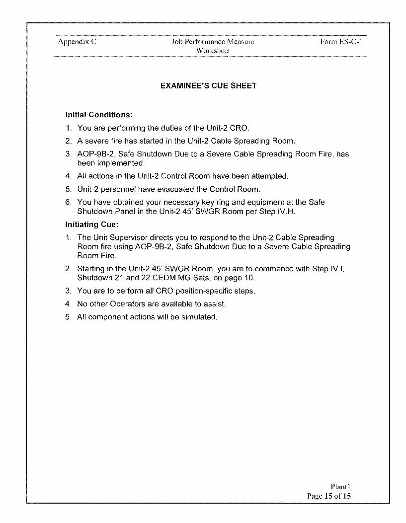
Appendix C
Initial Conditions:
Job Performance Measure Worksheet
EXAMINEE'S CUE SHEET
1. You are performing the duties of the Unit-2 CRO.
2. A severe fire has started in the Unit-2 Cable Spreading Room.
Form ES-C-1
3. AOP-98-2, Safe Shutdown Due to a Severe Cable Spreading Room Fire, has been implemented.
4. All actions in the Unit-2 Control Room have been attempted.
5. Unit-2 personnel have evacuated the Control Room.
6. You have obtained your necessary key ring and equipment at the Safe Shutdown Panel in the Unit-2 45' SWGR Room per Step IV.H.
Initiating Cue:
1. The Unit Supervisor directs you to respond to the Unit-2 Cable Spreading Room fire using AOP-98-2, Safe Shutdown Due to a Severe Cable Spreading Room Fire.
2. Starting in the Unit-2 45' SWGR Room, you are to commence with Step IV.I, Shutdown 21 and 22 CEDM MG Sets, on page 10.
3. You are to perform all CRO position-specific steps.
4. No other Operators are available to assist.
5. All component actions will be simulated.
Plant I Page 15 oflS
Calvert Cliffs Nuclear Power Plant
2018 NRC Initial Licensed Operator Exam
JPM-Plant2

Appendix C Job Performance Measure Worksheet
Facility: Calvert Cliffs 1 & 2
Alternate Path: No
Task Number: 204.137
Task Title:
Form ES-C-1
JPM Number: Plant2
Apply the watchstander's role as part of the Control Room Team in Normal, Abnormal, Emergency, and ERPIP situations
Task Standard:
This JPM is complete when local control has been established for 11 SWAC and 11 SWAC has been started, after 11 Cavity Cooling Fan Damper has been isolated for fire effects, and 11 SWGR HVAC is started.
Time Critical Task: No
K/A Reference: 068AA 1.21 (3.9/4.1)
Method of Testing: Simulated-Plant
Validation Time: 12 minutes
References and Tools Required:
1. AOP-9A-1, Control Room Evacuation and Safe Shutdown Due to a Severe Control Room Fire
JPM Setup Instructions:
1. AOP-9A-1, Control Room Evacuation and Safe Shutdown Due to a Severe Control Room Fire, printed single sided, in a procedure binder
Plant2 Page 2 of 11

Appendix C Job Performance Measure Worksheet Form ES-C-1
Directions to the Examinee:
I will explain the initial conditions, which steps to simulate or discuss, and provide initiating cues. When you complete the task successfully, the objective for this job performance measure will be satisfied.
Hand Examinee's Cue Sheet to Examinee at this time.
Initial Conditions:
1. You are performing the duties of the Unit-1 ABO.
2. A severe fire has started in the Control Room.
3. AOP-9A-1, Control Room Evacuation and Safe Shutdown Due to a Severe Control Room Fire, has been implemented.
4. You have obtained your necessary key ring and equipment at the Safe Shutdown Panel in the Unit-1 45' SWGR Room.
5. You are currently performing steps in the Unit-1 69' West Electrical Penetration Room.
6. You have just notified 1C43 that Channel D WRNI has been isolated from the Control Room per Step IV. BS.
Initiating Cue:
1. You are to commence with AOP-9A-1, Control Room Evacuation and Safe Shutdown Due to a Severe Control Room Fire, Step IV.BT, Start 11 Saltwater Air Compressor, on page 80.
2. You are to perform all remaining ABO position-specific steps.
3. No other Operators are available to assist.
4. All component actions will be simulated.
5. Are there any questions? You may begin.
Plant2 Page 3 of 11

Appendix C Job Performance Measure Worksheet Form ES-C-1
J-
STEP STANDARD J- <( ELEMENT <( en
en z :::,
TIME START:
CUE After Examinee reviews Cue Sheet, provide the examinee with a copy of AOP-9A-1.
Locates AOP-9A-1, Step IV.BT- Determines that next step to START 11 SALTWATER AIR be performed is IV. BT, to start COMPRESSOR 11 Saltwater Air Compressor
Any attempt to use the Radio is not effective.
CUE After Examinee contacts 1 C43 on the phone:
/ Load Center 11 Bis energized per Step BO.
I
Contact 1 C43 to verify Load Contacts 1 C43 by dialing
IV.BT Center 11 B is energized PER
either 3501, 5625, or 3511 on 1
[ Step BO. the telephone and verifies that Step BO has been completed
!
Comment
CUE After demonstrating inserting the key, key is fully inserted.
On north end of MCC 114R, Locates 11 SWAG controls in IV.BT insert key into 11 Saltwater Air U-1 69' West Electrical
2 Compressor Local/Remote Penetration Room and fully Handswitch, 1-HS-5204A 1. inserts key into 1-HS-5204A 1
Comment
- -
- -
- -
Plant2 Page 4 of 11
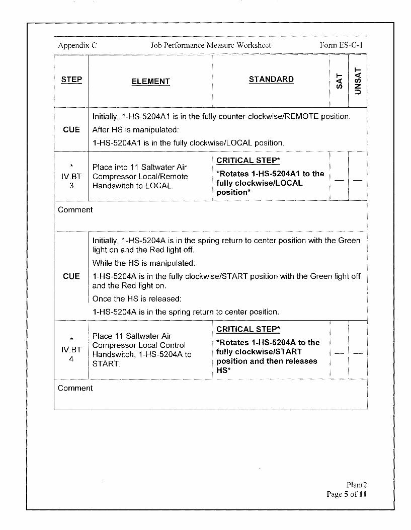
Appendix C Job Performance Measure Worksheet Form ES-C-1
I-
STEP STANDARD I- <( ELEMENT <( en
en z :::,
Initially, 1-HS-5204A 1 is in the fully counter-clockwise/REMOTE position.
CUE After HS is manipulated:
1-HS-5204A 1 is in the fully clockwise/LOCAL position.
CRITICAL STEP* * Place into 11 Saltwater Air
IV.BT Compressor Local/Remote *Rotates 1-HS-5204A 1 to the fully clockwise/LOCAL - -
3 Handswitch to LOCAL. position*
Comment
Initially, 1-HS-5204A is in the spring return to center position with the Green light on and the Red light off.
While the HS is manipulated:
CUE 1-HS-5204A is in the fully clockwise/START position with the Green light off and the Red light on.
, Once the HS is released:
1-HS-5204A is in the spring return to center position.
r
CRITICAL STEP* I I
* ! Place 11 Saltwater Air Compressor Local Control *Rotates 1-HS-5204A to the
IV.BT fully clockwise/START Handswitch, 1-HS-5204A to - -4
START. position and then releases HS*
Comment
Plant2 Page 5 of 11
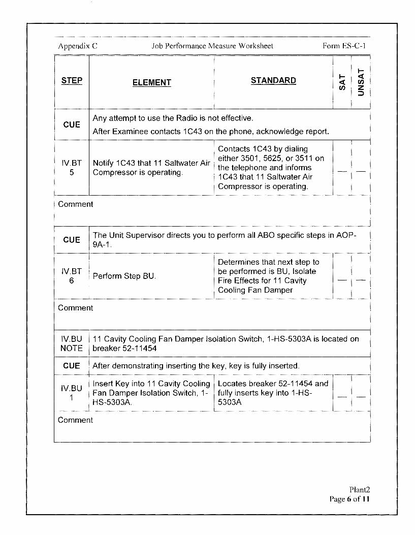
Appendix C Job Performance Measure Worksheet Form ES-C-1
I-
STEP STANDARD I- <t: ELEMENT <t: en
en z ::::>
CUE Any attempt to use the Radio is not effective.
After Examinee contacts 1 C43 on the phone, acknowledge report.
Contacts 1 C43 by dialing
IV.BT Notify 1 C43 that 11 Saltwater Air either 3501, 5625, or 3511 on
5 Compressor is operating. the telephone and informs - -1 C43 that 11 Saltwater Air Compressor is operating.
Comment
CUE The Unit Supervisor directs you to perform all ABO specific steps in AOP-9A-1.
I Determines that next step to
IV.BT 1 Perform Step BU. be performed is BU, Isolate
6 Fire Effects for 11 Cavity - -
I Cooling Fan Damper
Comment
IV.BU 11 Cavity Cooling Fan Damper Isolation Switch, 1-HS-5303A is located on NOTE breaker 52-11454
CUE After demonstrating inserting the key, key is fully inserted.
IV.BU Insert Key into 11 Cavity Cooling Locates breaker 52-11454 and
1 Fan Damper Isolation Switch, 1- fully inserts key into 1-HS-HS-5303A. 5303A
Comment
- -
Plant2 Page 6 of 11
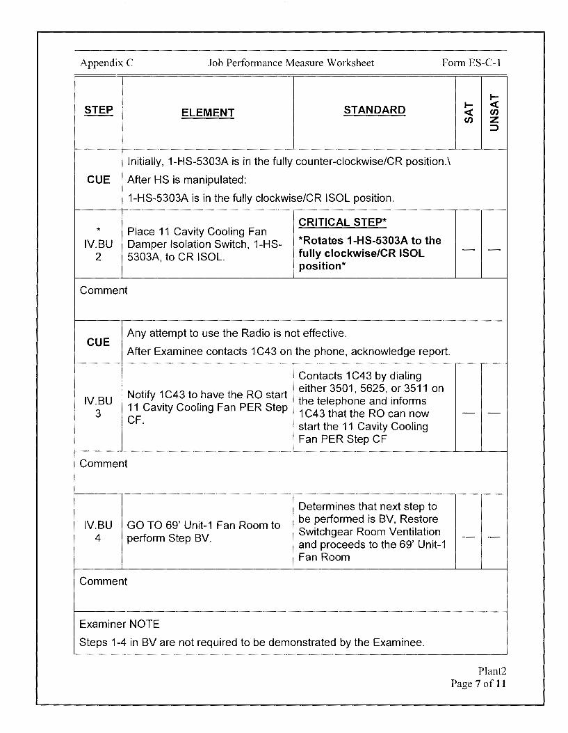
Appendix C Job Performance Measure Worksheet Form ES-C-1
STEP ELEMENT STANDARD
Initially, 1-HS-5303A is in the fully counter-clockwise/CR position.\
CUE After HS is manipulated:
1-HS-5303A is in the fully clockwise/CR ISOL position.
CRITICAL STEP* * Place 11 Cavity Cooling Fan
IV.BU Damper Isolation Switch, 1-HS- *Rotates 1-HS-5303A to the fully clockwise/CR ISOL 2 5303A, to CR ISOL. position*
Comment
CUE Any attempt to use the Radio is not effective.
After Examinee contacts 1 C43 on the phone, acknowledge report.
I Contacts 1 C43 by dialing I
· Notify 1 C43 to have the RO start erther3501,5625,or3511 on
IV.BU I 11 Cavity Cooling Fan PER Step
the telephone and informs 3 1 C43 that the RO can now
! CF. start the 11 Cavity Cooling Fan PER Step CF
Comment
Determines that next step to
IV.BU GO TO 69' Unit-1 Fan Room to be performed is BV, Restore
4 perform Step BV. Switchgear Room Ventilation and proceeds to the 69' Unit-1 Fan Room
Comment
Examiner NOTE
Steps 1-4 in BV are not required to be demonstrated by the Examinee.
~ ~ <( <( Cl) Cl) z
:::>
- -
- -
- -
Plant2 Page 7 of 11

Appendix C Job Performance Measure Worksheet Form ES-C-1
1--
STEP STANDARD 1-- <{ ELEMENT <{ U)
U) z :,
Once Examinee enters the 69' Unit-1 Fan Room: CUE Steps BV 1-3 have been completed by an extra Equipment Operator.
Perform remainder of ABO actions startinQ at Step IV.BV.5. IV.BV
Equipment to tie the damper is located at 11 SWGR HVAC NOTE
Determines steps 1-3 have
IV.BV Tie open ATMOS DISCH been completed by another Equipment Operator based on
1 GRAVITY DMPR, 1-HVAC-230 Cue.
Proceeds to step 5.
Comment
Any attempt to use the Radio is not effective.
CUE After Examinee contacts 1 C43 on the phone:
Load Center 11A is energized per Step BN.
Contact 1 C43 to verify Load Contacts 1 C43 by dialing
IV.BV either 3501, 5625, or 3511 on 5
Center 11A is energized PER the telephone and verifies that
Step BN. Step BN has been completed
Comment
- -
- -
Plant2 Page 8 of 11
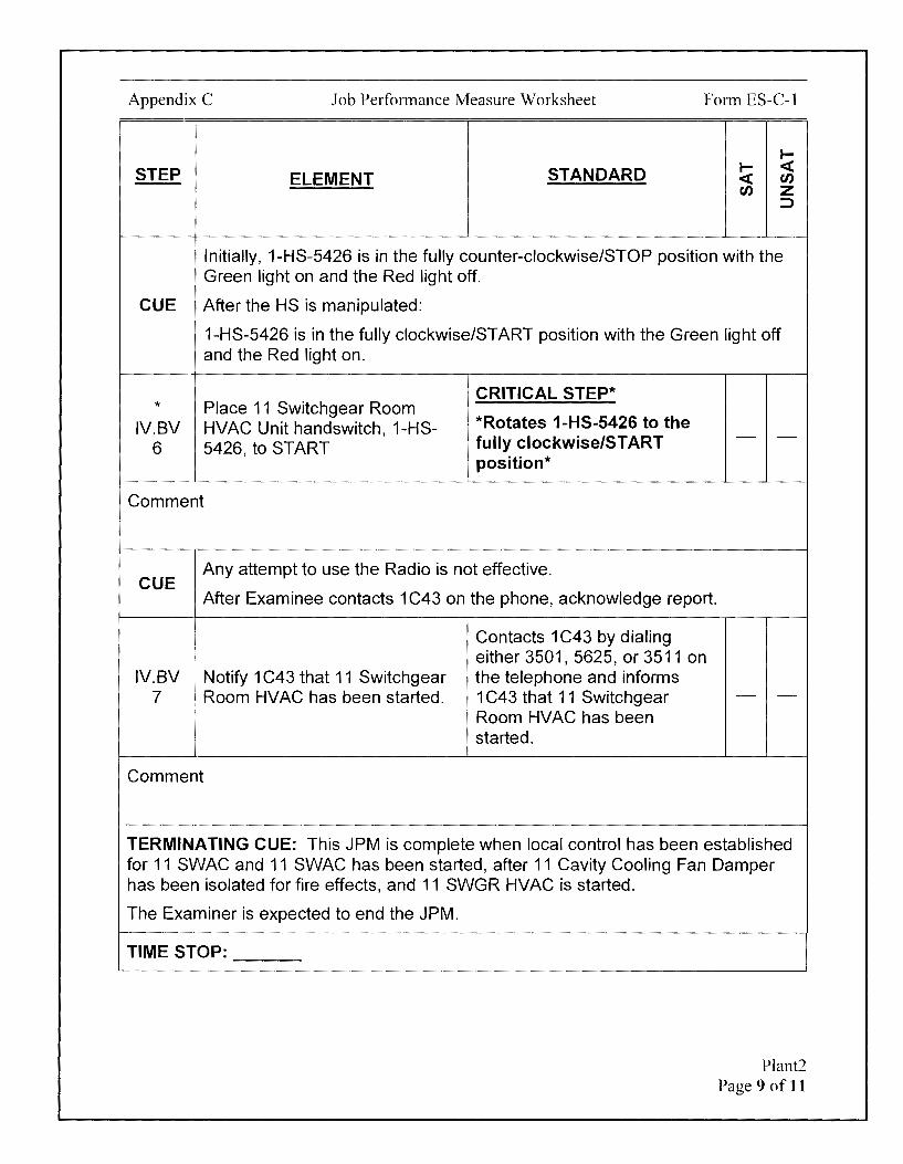
Appendix C Job Performance Measure Worksheet Form ES-C-1
I-
STEP STANDARD I- <( ELEMENT <( rn
rn z :::>
Initially, 1-HS-5426 is in the fully counter-clockwise/STOP position with the Green light on and the Red light off.
CUE After the HS is manipulated:
1-HS-5426 is in the fully clockwise/START position with the Green light off and the Red light on.
CRITICAL STEP* * Place 11 Switchgear Room
IV.BV HVAC Unit handswitch, 1-HS- *Rotates 1-HS-5426 to the fully clockwise/START - -
6 5426, to ST ART position*
Comment
CUE Any attempt to use the Radio is not effective.
After Examinee contacts 1 C43 on the phone, acknowledge report.
Contacts 1 C43 by dialing either 3501, 5625, or 3511 on
IV.BV I Notify 1 C43 that 11 Switchgear the telephone and informs 7 i Room HVAC has been started. 1 C43 that 11 Switchgear - -
I Room HVAC has been started.
Comment
TERMINATING CUE: This JPM is complete when local control has been established for 11 SWAC and 11 SWAC has been started, after 11 Cavity Cooling Fan Damper has been isolated for fire effects, and 11 SWGR HVAC is started.
The Examiner is expected to end the JPM.
TIME STOP:
Plant2 Page 9 of 11
Appendix C Job Performance Measure Worksheet
Verification of Completion
Job Performance Measure Number: Plant2
Examinee:
NRC Examiner:
Date Performed:
Facility Evaluator: ________________ _
Number of Attempts: _______________ _
Time to Complete: ________________ _
Follow up Question(s):
Examinee Response:
Result: SATISFACTORY UNSATISFACTORY -- --
Examiner's Signature and Date:
Form ES-C-1
Plant2 Page 10 of 11

Appendix C
Initial Conditions:
Job Performance Measure Worksheet
EXAMINEE'S CUE SHEET
1. You are performing the duties of the Unit-1 ABO.
2. A severe fire has started in the Control Room.
Form ES-C-1
3. AOP-9A-1 , Control Room Evacuation and Safe Shutdown Due to a Severe Control Room Fire, has been implemented.
4. You have obtained your necessary key ring and equipment at the Safe Shutdown Panel in the Unit-1 45' SWGR Room.
5. You are performing steps in the Unit-1 69' West Electrical Penetration Room.
6. You have just notified 1 C43 that Channel D WRNI has been isolated from the Control Room per Step IV.BS.
Initiating Cue:
1. You are to commence with AOP-9A-1, Control Room Evacuation and Safe Shutdown Due to a Severe Control Room Fire, Step IV.BT, Start 11 Saltwater Air Compressor, on page 80.
2. You are to perform all remaining ABO position-specific steps.
3. No other Operators are available to assist.
4. All component actions will be simulated.
Plant2 Page 11 of 11

Calvert Cliffs Nuclear Power Plant
2018 NRC Initial Licensed Operator Exam
JPM-Plant3

Appendix C Job Performance Measure Worksheet Form ES-C-1
Facility: Calvert Cliffs 1 & 2
Alternate Path: No
JPM Number: Plant3
Task Number: 002.018
Task Title: Place/Remove a 125VDC Battery Charger in/from service
Task Standard:
This JPM is complete when 21 Battery Charger is started and sharing load on 21 DC Bus with 13 Battery Charger.
Time Critical Task: No
KIA Reference: 063A3.01 (2.7/3.1)
Method of Testing: Simulated-Plant
Validation Time: 11 minutes
References and Tools Required:
1. Ol-26A, 125 Volt Vital DC
2. SA-CA-129-1001, Electrical Safety Task Matrices/PPE Requirements
JPM Setup Instructions:
1. Ol-26A, 125 Volt Vital DC, printed single sided.
2. SA-CA-129-1001, Electrical Safety Task Matrices/PPE Requirements, Attachment 1, printed single sided.
Plant3 Page 2 of 13
Appendix C Job Performance Measure Worksheet Form ES-C-1
Directions to the Examinee:
I will explain the initial conditions, which steps to simulate or discuss, and provide initiating cues. When you complete the task successfully, the objective for this job performance measure will be satisfied.
Hand Examinee's Cue Sheet to Examinee at this time.
Initial Conditions:
1. You are performing the duties of the Unit-2 CRO.
2. 21 Battery Charger was removed from service for emergent maintenance.
3. 21 DC Bus has remain energized with 13 Battery Charger in service during the 21 Battery Charger maintenance window. 13 Battery Charger DC OUTPUT amps are currently 110 Amps and steady.
4. All repairs to the 21 Battery Charger have been completed.
5. The Clearance was removed with the following conditions:
• 480V load center breaker for the 21 Battery Charger, 52-2407, left in the CLOSED position
• 21 Battery Charger AC INPUT breaker left in the OFF position • 21 Battery Charger DC OUTPUT breaker left in the OFF position. • 21 BATT CHGR FUSED DISC SW, 95-2102, left in the OFF position
6. PPE requirements were identified at the brief as 100% cotton long-sleeve shirt and pants and safety glasses.
7. You are wearing a 100% cotton long-sleeve shirt and pants.
Initiating Cue:
1. The Unit Supervisor directs you to place 21 Battery Charger in service Ol-26A, 125 Volt Vital DC.
2. All component actions will be simulated.
3. Are there any questions? You may begin.
Plant3 Page 3 of 13

Appendix C Job Performance Measure Worksheet Form ES-C-1
I-
STEP STANDARD I- <( ELEMENT <( en
en z :::>
TIME START:
CUE After Examinee reviews Cue Sheet, provide the examinee with a copy of 01-26A.
Locates Ol-26A Step 6.4, Determines that 01 section to Placing a Battery Charge in return 21 Battery Charger to - -
i Service service is Ol-26A Step 6.4
Comment
6.4 '
1
Initial Conditions NIA A
Examiner NOTE
It is not intended for the Examinee to locally evaluate 21 DC Bus and 13 Battery Charger status.
If the Examinee is evaluating 21 DC Bus and 13 Battery Charger status:
CUE 21 DC bus has remain energized with 13 Battery Charger in service during the entire maintenance window.
The DC bus is energized from Based on the Cue Sheet,
6.4 determines that 21 DC bus A.1
the Battery and/or the other has remain energized with 13 - -
Battery Charger. Battery Charger in service
Comment
Examiner NOTE
It is not intended for the Examinee to locally verify that the 480V load center feeder breaker for 21 Battery Charger is closed.
Plant3 Page 4 of 13

Appendix C Job Performance Measure Worksheet Form ES-C-1
.... STEP STANDARD .... < ELEMENT < en
en z :::>
If the Examinee is evaluating 480V load center feeder breaker status:
CUE Power is available to the 21 Battery Charger with 480V load center breaker 52-2407 in the CLOSED position.
Based on the Cue Sheet, determines that power is
6.4 The associated 480V load available to the 21 Battery A.2 center breaker is closed. Charger with 480V load center - -
breaker 52-2407 in the CLOSED position
Comment
CUE AC INPUT volts, DC OUTPUT amps, and DC OUTPUT volts on Panel 2005 all read zero.
Indication is available for Battery 6.4 A.3
Charger output voltage and current.
Comment
6.4 Procedure
B
Locates 21 Battery Charger in the U-2 Cable Spreading Room. Evaluates voltage and output indications on Panel 2005 and determines indications are available for 21 Battery Charger output voltage and current
NIA
- -
Plant3 Page 5 of 13

Appendix C Job Performance Measure Worksheet Form ES-C-1
I-
STEP STANDARD I- <C ELEMENT <C en
en z :::>
CUE DC OUTPUT breaker on Panel 2005 is in the full down/OFF position.
Verifies position of DC 6.4 CHECK the Battery Charger DC OUTPUT breaker on Panel B.1 OUTPUT BREAKER is OFF. 2005 is in the full down/OFF - -
position.
Comment
CUE AC INPUT breaker on Panel 2005 is in the full down/OFF position.
6.4 CHECK the Battery Charger AC Verifies position of AC INPUT INPUT CIRCUIT BREAKER is breaker on Panel 2005 is in
B.2 OFF. the full down/OFF position.
Comment
Initially, 95-2102 is in the fully clockwise/down/OFF position.
CUE After BATT CHGR FUSED DIS SW is manipulated:
95-2102 is in the fully counter-clockwise/up/ON position.
CRITICAL STEP*
Determines BATT CHGR FUSED DIS SW to be operated is 95-2102.
* Check the BATT CHGR FUSED 6.4 DIS SW for the battery charger
*While wearing Safety Glasses, rotates BATT
B.3 being placed in service is ON: CHGR FUSED DIS SW 95-2102 on 2001 counter-clockwise to the fully counter-clockwise/up/ON position*
Comment
- -
- -
Plant3 Page 6 of 13
Appendix C Job Performance Measure Worksheet Form ES-C-1
I-
STEP STANDARD I- <( ELEMENT <( (/)
(/) z :::>
CUE 2001 bus amps read O amps and bus voltmeter reads 133 volts.
Check the associated DC bus Locates bus voltmeter on 6.4 voltmeter on 1 (2)001 OR 2001 and determines DC bus B.4 - -1(2)002 indicates 125 to 137.5
I voe. volts are within desired range
Comment
Initially, DC OUTPUT breaker on Panel 2005 is in the full down/OFF position.
CUE After the breaker is manipulated:
21 Battery Charger DC OUTPUT breaker on Panel 2005 is in the full up/ON position.
CRITICAL STEP*
* *While wearing Safety
6.4 Place the Battery Charger DC Glasses, places 21 Battery OUTPUT BREAKER to ON. Charger DC OUTPUT - -
B.5 breaker on Panel 2D05 to full up/ON position*
Comment
CUE
6.4 B.6
Comment
Red light for "REVERSE POLARITY" on Panel 2005 is dark/not lit.
Locates red "REVERSE Check the "REVERSE POLARITY" lamp on Panel POLARITY" lamp is NOT lit. 2005 and determines lamp is
not on. - -
Plant3 Page 7 of 13
Appendix C Job Performance Measure Worksheet Form ES-C-1
I-
STEP STANDARD I- <( ELEMENT <( Cl)
Cl) z :)
6.4 Trouble lights will cycle on and off until the Charger has stabilized on the
B.7 NOTE
bus.
Initially, AC INPUT breaker on Panel 2005 is in the full down/OFF position, AC INPUT volts, DC OUTPUT amps, and DC OUTPUT volts on Panel 2D05
I all read zero. I
CUE After the breaker is manipulated:
, 21 Battery Charger AC INPUT breaker on Panel 2D05 is in the full up/ON I position ' DC OUTPUT volts on Panel 2D05 rise to 134 VDC and steadies
DC OU PUT amps on Panel 2D05 rise to 10 amps and steadies All red trouble liQht blink once and then QO out/are dark.
CRITICAL STEP*
* *While wearing Safety
6.4 Place the Battery Charger AC Glasses, places 21 Battery INPUT BREAKER to ON. Charger AC INPUT breaker - -
B.7 on Panel 2005 to full up/ON position*
Comment
6.4 As battery charge assumes load, the amperage indication will rise to some
B.8 NOTE
CUE
6.4 B.8
Comment
value and stabilize.
DC OUTPUT volts on Panel 2D05 rises to 134 VDC and steadies.
Check the Battery Charger Evaluates DC OUTPUT volts on Panel 2D05 and
voltage is indicating between determines DC OUTPUT volts
125 and 137.5 voe. are within desired range
- -
Plant3 Page 8 of 13
Appendix C Job Performance Measure Worksheet Form ES-C-1
I-
STEP STANDARD I- <( ELEMENT <( fl')
fl') z ::::>
6.4 When the chargers set voltage is reached, the Charger Ammeter will 8.9 indicate a composite of required bus current and battery float current. This
NOTE composite current will always be above O amps.
Examiner NOTE
When 21 Battery Charger initially assumes load, 13 Battery Charger DC OUTPUT amps will lower from initial 150 amps to 140 amps. The Battery Chargers will not be sharing load properly until the SHARING LOAD RESET is depressed. After the SHARING LOAD RESET is depressed, 13 Battery Charger DC OUTPUT amps will lower from 140 amps to 80 amps while 21 Battery Charger DC OUTPUT amps rise from 10 amps to 70 amps.
CUE DC OUTPUT amps on Panel 2005 read 10 amps and steady.
If evaluated, DC OUTPUT amps on Panel 1007 read 140 amps and steady.
Check the Battery Charger DC Evaluates DC OUTPUT amps
6.4 on Panel 2005 and 8.9
Ammeter is indicating greater determines DC OUTPUT - -
than O amps. amps are within desired range
Comment
CUE No red TROUBLE lights are lit/on.
Evaluates red TROUBLE 6.4 Check that NO TROUBLE lights lights on Panel 2005 and
8.10 are lit. determines that no TROUBLE - -lights are on.
Comment
6.4 Master and Slave load currents should begin to slowly converge until they
8.11 NOTE
are within 50 amps of each other.
Plant3 Page 9 of 13

Appendix C Job Performance Measure Worksheet Form ES-C-1
I-
STEP STANDARD I- <( ELEMENT <( en
en z :::>
IF load sharing with similar style Determines step is applicable
6.4 since 13 and 21 Battery B.11
Charger, THEN CHECK the Chargers are similar style - -
Load Sharing operation: Chargers.
Comment
CUE 21 Battery Charger EQUALIZE TIMER on Panel 2D05 reads zero and 13 Battery Charger EQUALIZE TIMER on Panel 1 DO? reads zero.
Checks 21 Battery Charger
i EQUALIZE TIMER on Panel 2D05 and 13 Battery Charger
VERIFY that both equalize EQUALIZE TIMER on Panel 6.4
timers are in the timed out 1D07. B.11.a
position. Determines both equalize timers are timed out based on both EQUALIZE TIMERs reading zero.
Comment
- -
Plant3 Page 10 of 13
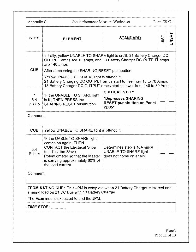
Appendix C Job Performance Measure Worksheet Form ES-C-1
I-
STEP STANDARD I- <C ELEMENT <C en
en z :::>
Initially, yellow UNABLE TO SHARE light is on/lit, 21 Battery Charger DC OUTPUT amps are 10 amps, and 13 Battery Charger DC OUTPUT amps are 140 amps.
CUE After depressing the SHARING RESET pushbutton:
Yellow UNABLE TO SHARE light is off/not lit. 21 Battery Charging DC OUTPUT amps start to rise from 10 to 70 Amps. 13 Battery Charger DC OUTPUT amps start to lower from 140 to 80 Amps.
CRITICAL STEP* * IF the UNABLE TO SHARE light
6.4 *Depresses SHARING is lit, THEN PRESS the RESET pushbutton on Panel - -
B.11.b SHARING RESET pushbutton. 2005*
Comment
CUE Yellow UNABLE TO SHARE light is off/not lit.
IF the UABLE TO SHARE light comes on again, THEN
6.4 I CONTACT the Electrical Shop Determines step is N/A since
B.11.c , to adjust the Slave UNABLE TO SHARE light - -Potentiometer so that the Master does not come on again
I is carrying approximately 60% of the load current.
i
Comment
TERMINATING CUE: This JPM is complete when 21 Battery Charger is started and sharing load on 21 DC Bus with 13 Battery Charger.
The Examinee is expected to end the JPM.
TIME STOP:
Plant3 Page 11 of 13

Appendix C Job Performance Measure Worksheet
Verification of Completion
Job Performance Measure Number: Plant3
Examinee:
NRC Examiner:
Date Performed:
Facility Evaluator: ________________ _
Number of Attempts: _______________ _
Time to Complete: ________________ _
Follow up Question(s):
Examinee Response:
Result: SATISFACTORY UNSATISFACTORY -- --
Examiner's Signature and Date:
Form ES-C-1
Plant3 Page 12 of 13

Appendix C
Initial Conditions:
Job Performance Measure Worksheet
EXAMINEE'S CUE SHEET
1. You are performing the duties of the Unit-2 CRO.
Form ES-C-1
2. 21 Battery Charger was removed from service for emergent maintenance.
3. 21 DC Bus has remain energized with 13 Battery Charger in service during the 21 Battery Charger maintenance window. 13 Battery Charger DC OUTPUT amps are currently 110 Amps and steady.
4. All repairs to the 21 Battery Charger have been completed.
5. The Clearance was removed with the following conditions:
• 480V load center breaker for the 21 Battery Charger, 52-2407, left in the CLOSED position
• 21 Battery Charger AC INPUT breaker left in the OFF position • 21 Battery Charger DC OUTPUT breaker left in the OFF position. • 21 BATT CHGR FUSED DISC SW, 95-2102, left in the OFF position
6. PPE requirements were identified at the brief as 100% cotton long-sleeve shirt and pants and safety glasses.
7. You are wearing a 100% cotton long-sleeve shirt and pants.
Initiating Cue:
1. The Unit Supervisor directs you to place 21 Battery Charger in service Ol-26A, 125 Volt Vital DC.
2. All component actions will be simulated.
Plant3 Page 13 of 13
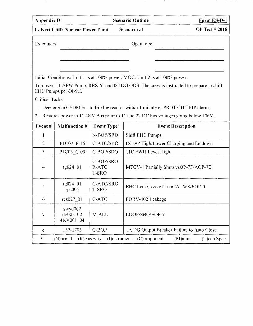
Appendix D Scenario Outline Form ES-D-1
Calvert Cliffs Nuclear Power Plant Scenario #1 OP-Test# 2018
Examiners: Operators:
Initial Conditions: Unit-I is at 100% power, MOC. Unit-2 is at 100% power.
Turnover: 11 AFW Pump, RRS-Y, and OC DG OOS. The crew is instructed to prepare to shift EHC Pumps per 0I-9C.
Critical Tasks
1. Deencrgize CEDM bus to trip the reactor within 1 minute of PROT CH TRIP alarm.
2. Restores power to 11 4KV Bus prior to 11 and 22 DC bus voltages going below 106V.
Event# Malfunction # Event Type* Event Description
1 N-BOP/SRO Shift EHC Pumps
2 PIC07 F-16 C-ATC/SRO IX DIP High/Lower Charging and Letdown 1 Pl C03 C-09 C-BOP/SRO 11 C FWH Level High .)
-
C-BOP/SRO 4 tg024_01 R-ATC MTCV-1 Partially Shuts/ AOP-7F / AOP-7E
T-SRO
5 tg024_01 C-ATC/SRO
EHC Leak/Loss of Load/ A TWS/EOP-0 rps005 T-SRO
6 rcs027 01 C-ATC PORV-402 Leakage
swyd002 7 i dg002_02 M-ALL LOOP/SBO/EOP-7
' 4KV001 04
8 152-1703 C-BOP IA DG Output Breaker Failure to Auto Close
* (N)ormal (R)eactivity (I)nstrument (C)omponent (M)ajor (T)ech Spec
Appendix D Scenario Outline
Calvert Cliffs Nuclear Power Plant Scenario #1
Scenario Overview
Initial Conditions: Unit-1 at 100% power, MOC Unit-2 at I 00% power Equipment OOS: 11 AFW Pump, RRS-Y and OC DG OOS Abnormal Conditions: Maximizing purification due to high sulfates Instructions for shift: Shift EHC Pumps due to high vibrations on 11 EHC Pump
Event 1
Form ES-D-1
OP-Test# 2018
The crew will start 12 EHC Pump and then secure 11 EHC pump per OI-9C due to high vibrations identified by Condition Monitoring.
Event 2 The crew will receive a CVCS Purification IX DIP high alarm on 1C07. The IX's will be immediately bypassed. Chemistry will request that Charging and letdown be lowered and the IX be placed back in service until another Purification IX can be loaded. The crew will lower Charging and Letdown to one Charging Pump and restore purification flow per OI-2A.
Event 3 11 C FWH Level will drift high due to a faulty Level Controller and level will challenge Turbine Trip values. The crew will respond using the 1 C03 Alarm Manual and manually open the High Level Dump CV to prevent a Turbine Trip and isolate air to the control valve.
Event 4 A Main Turbine Control Valve (MTCV) will partially fail shut, causing a loss of load. Temperature will rise and exceed DNB Tech Spec 3.4.1 limits. The crew will take immediate actions and lower power per AOP-7F to restore RCS temperature to program. The crew will also implement AOP-7E for the Turbine Valve malfunction and adjust the TBV controller to minimize further transients caused by the partially open MTCV going further shut.
Event 5 A large EHC leak will develop causing two of the MTCVs to rapidly shut. RCS temperature will exceed DNB Tech Spec 3.4.1 limits and PZR level will exceed Tech Spec 3.4.9 limits. The loss of load will result in a high RCS Pressure condition reaching trip criteria. RPS will not automatically trip the reactor. The crew will need to recognize manual trip failure and implement EOP-0. The crew will perform the Critical Task of deenergizing the CED Ms in order to trip the reactor
Event 6 A PORV that lifts due to the high RCS pressure condition will remain partially open, resulting in a RCS leak. The crew will note the lowering RCS pressure trend in EOP-0 and manually isolate the leaking PORV by shutting the PORV Block MOV. RCS temperature will also be controlling lower than normal due to the TBV Controller setting established in AOP-7E, requiring the Controller setpoint to be restored to normal to restore temperature.
Page 2 of27
Appendix D Scenario Outline Form ES-D-1
Calvert Cliffs Nuclear Power Plant Scenario #1 OP-Test# 2018
Event 7 Once RCS temperature and pressure are restoring, a Loss of Offsite power will occur. The IA DG will fail to start and the 14 4K v Bus will fault, resulting in a Station Blackout. The crew will establish RCS heat removal by initiating AFW and directing local control of the ADV s. The crew will implement EOP-7 and verify the MSIV s are shut to protect the condenser. RCP bleedoff will be isolated to minimize RCS inventory loss. The Main Feedwater System will be secured. The electrical system will be aligned for restoration and the 1 A DG will be returned to service. The crew will direct local restart of the DG.
Event 8 When the 1 A DG is started, the output breaker will not auto close. The crew will need to manually close the breaker to complete the Critical Task ofrestoring power to the 11 4KV bus.
If plant conditions degrade or the crew is unsure of the diagnosis it is acceptable for them to enter EOP-8 instead ofEOP-7. lfEOP-8 is entered, all critical tasks still apply unless individual tasks are invalidated by the exam team.
Page 3 of27

Appendix D Scenario Outline Form ES-D-1
Calvert Cliffs Nuclear Power Plant Scenario #1 OP-Test# 2018
Scenario Setup Instructions
1. Reset to IC-34.
2. Place simulator in RUN and advance charts.
3. Place simulator in FREEZE.
4. Enter Triggers:
a. CEA_ROD_POSITION(l) < 5 (CEA 01 on bottom (IYlO required)) on event 6
b. P 1 C03 _ l HS 1451 _ SW OPEN (11 C FWH Dump Opened) on event 18
c. P1C07_1HS2520_SWBYPASS (CVCS IX Bypassed) on event 19
5. Enter ,\1alfunctions:
a. afwOOl 01 -
b. dg002_01
C. tg024_01 to 40.0 on event 4
d. rps005 on event 5
e. rps006 on event 5
f. esfa008 01 on event 5
g. esfa008 02 on event 5
h. tg024_01 to O on event 5
I. tg004 _ 02 after 15 on event 5
J· rcs027 01 after 120 to 10.0 on event 6
k. swvd002 on event 7
l. dg002 _ 02 on event 7
m. 4h001 04 on event 7
n. dgOO l _ 02 on event 16
6. Enter Remote Functions:
a. l-MS-3988 after 5 to 1.0
Page 4 of27

Appendix D Scenario Outline Form ES-D-1
Calvert Cliffs Nuclear Power Plant Scenario #1 OP-Test# 2018
7. Enter Panel Overrides:
8.
9.
a. P1C04 1STP3986 LTREDtooff - -
b. Pl C04 1 STP3986 LTWHIT to off - -
C. Pl C04 1HS3986 LTWHIT to off - -
d. PIC07 F16 LTON to On on event 2 - -
e. P1C07 F16 LTONafter20to0ffonevent 19 - -
f. P1C03 1LI1450 MT to 5.50000 on event 3 - -
g. P 1 C03 C09 L TON to On on event 3 - -
h. P 1 C03 11 CFWHTR L TBRI to On on event 3 - -
I. Pl C03 1LI1450 MT from 5.50000 to -5 in 60 on event 18
J. Pl C03 C09 LTON to Off on event 18
k. P 1 C03 11 CFWHTR L TBRI to Off on event 18 - -
I. Pl Cl 8A KFl 703 to TRIP on event 7
Administrative:
a. Upper Right Mk 6 screen set to lube-hyd oil on 1 CO2 (with EHC pressures visible)
b. Place an "INFO" tag on 11 AFW Pump indication.
C.
d.
Place Protected Equipment tags on 12 and 13 AFW Pumps.
Place an off normal tag on RRS-Y.
e. Raise Charging and Letdown with 11 and 12 Charging Pumps in service per OI-2A, Step 6.3.
f.
g.
h.
Start 12 CR HV AC.
Secure 11 CR HV AC.
Place OC DG Output breaker in Pull To Lock.
I. Place "INFO" tags on OC DG Output Breaker, OC Emergency Start, and OC Slow Start pushbuttons.
J. Ensure correct magnetic plaques are in place.
Independently verify correct completion of the following:
a. Event Triggers correctly entered
b. Malfunctions correctly entered
c. Remote Functions correctly entered
d. Panel Overrides correctly entered
e. Administrative actions correctly performed
Page 5 of27
Appendix D Scenario Outline Form ES-D-1
Calvert Cliffs Nuclear Power Plant Scenario #1 OP-Test# 2018
10. Place simulator in RUN.
11. Ensure schedule files are in RUN.
12. Ensure Trigger files are in RUN.
13. Reset/Acknowledge panel and PPC alarms.
14. Ensure all PPC screens selected to Main Menu, Alarms, or SPDS Operating Summary page.
15. Select "Clock" and ensure "Horn On" for annunciators.
16. Brief the Crew:
I. Present plant conditions: Both Units are at I 00% power
Unit-I is in MOC
2. Power history: Unit-I has been at I 00% for last 3 months
RRS-Y ,, Equipment out of .) .
OCDG service:
11 AFW Pump
2 Charging Pumps in service due to high RCS sulfates
4. Abnormal conditions: 12 Charging Pump has developed a 0.03 GPM packing leak. When charging can be shifted/lowered, secure 12 Charging Pump.
5. Surveillances due: None
6. Instructions for shift: Shift to 12 EHC Pump due to higher vibrations on 11 EHC Pump and through Filter I
17. Allow crew 3-5 minutes to acclimate themselves with their positions.
Page 6 of27

Appendix D Scenario Outline Form ES-D-1
Calvert Cliffs Nuclear Power Plant Scenario #1 OP-Test# 2018
18. Instructions for the Booth Operator:
a. Event 1 : When directed by Lead Examiner, call into Control Room as TBO and report 'Tm on station and ready for shift of EHC pumps."
b. Event 2: Activate IX DIP High/Lower Charging and Letdown when directed by Lead Examiner.
c. Event 3: Activate 11 C FWH Level High when directed by Lead Examiner.
d. Event 4: Activate MTCV-1 Partially Shuts/AOP-7F/AOP-7E when directed by Lead Examiner.
e. Event 5: Activate EHC Leak/Loss of Load/ATWS/EOP-0 when directed by Lead Examiner
f. Event 6: No actions in booth necessary to activate PORV-402 Leakage.
g. Event 7: Activate EHC Leak/Loss ofLoad/ATWS/EOP-0 when directed by Lead Examiner.
h. Event 8: When directed by Lead Examiner, call into Control Room as WEC and report "IA DG issues have been repaired. The IA DG is available.
Page 7 of27

Appendix D Scenario Outline Form ES-D-1
Calvert Cliffs Nuclear Power Plant Scenario #1 OP-Test# 2018
Responses to Crew Requests
If a request and response is not listed, delay the response until reviewed with the examiner. If one request is dependent upon completion of another, then subsequent actions should not be responded to until the appropriate time delay has been observed. Responses to routine requests, which have no effect the scenario, do not require examiner clearance.
Allow 2-3 minutes to perform requests from or to give reports to the Control Room unless otherwise specified.
•:> \i;, :>~{, V
1{]3SPQN;Sl; :. REQUEST <"',/
' ... . ... ·,,"'•/,, · .. · . Event 1- Shift EHC Pumps
Acknowledge request. I. Place Filter I in service. • After 2 minutes, report Filter I is in
service.
2. WEC informed of EHC pump shift. Acknowledge request. No further actions are required.
Event 2- IX DIP High/Lower Charging and Letdown.
I. WEC informed of high IX DIP. Acknowledge request. No further actions are required.
Acknowledge request.
• Immediately report "Local DIP is 50
2. Investigate high IX DIP. PSID. I had a note on my turnover that IX DIP was approaching the high limit and Chemistry may ask for lower purification flow if that happens."
Acknowledge information.
• Immediately report "RCS chemistry is still elevated due to sulfates. We need to
3. Chemistry informed of high IX DIP. minimize the time without purification. We would like you to lower Charging and Letdown and then place the IXs back in service until another IX bed can be prepared for purification."
4. Rad Con Shift Supervisor informed of Acknowledge request. No further actions are change in eves lineup. required.
5. Chemistry informed of change in CVCS Acknowledge request. No further actions are lineup. required.
Acknowledge request. 6. Flowrate on Process Rad Monitor. • After I minute report "Process Rad
Monitor flow rate is I GPM."
Page 8 of27
Appendix D Scenario Outline Form ES-D-1
Calvert Cliffs Nuclear Power Plant Scenario #1 OP-Test# 2018
REQUEST RESPONSE
Event 3-11 C FWH Level High
1. WEC informed of 11 C FWH level issue. Acknowledge request. No further actions are required.
Acknowledge request.
• After 2 minutes, report "I hear a small air 2. Investigate 11 C FWH level and control leak inside LC-1450 controller."
systems. • If the High Level dump valve is open, report "The NLCV, HDV-1450-CV, is shut."
Acknowledge request. 3. Isolate NLCV Air Isolation and bleed off the • After 3 minutes, report "The air isolation
air. is shut and air has been bled off the 11 C FWHNLCV."
4. Place 11 C FWH in service. Acknowledge request. No further actions are required.
Event 4-MTCV-1 Partially Shuts/AOP-7F/AOP-7E
1. WEC informed of MTCV issue. Acknowledge request. No further actions are required.
2. Notify Main Turbine System Engineer and Acknowledge request. No further actions are support. required.
Acknowledge request.
• After 2 minutes, report "MTCV-1 is open
3. Local indications at MTCV -1. - 40% locally. There is a small EHC leak on the actuator and we have adequate spill prevention controls to capture the EHC fluid."
Page 9 of27

Appendix D Scenario Outline Form ES-D-1
Calvert Cliffs Nuclear Power Plant Scenario #1 OP-Test# 2018
REQUEST RESPONSE
Event 5- EHC Leak/Loss of Load/ATWS/EOP-0
Acknowledge request.
• After 2 minutes report "All MTCVs and MTSVs are shut. EHC leakage has
1. Local status of MTCV s. stopped, but it looks like the leak on MTCV -1 got larger and a leak started on MTCV-2 as well. All EHC fluid is being adequately contained."
Event 6- PORV-402 Leakage
1. WEC informed of PORV issue. Acknowledge request. No further actions are required.
Event 7- LOOP/SBO/EOP-7
Acknowledge request.
• After I minutes, position ADV (I-MS-
1. Manually operate ADV s. 3938-CV and l-MS-3939-CV using Remotes with a I minute ramp.
• After an additional minute, report ADVs are positioned as requested.
Acknowledge request. 2. Verify SWGR ventilation in service per 01- • After 2 minutes report "Neither 11 or 12
22H. SWGR HY AC are in service due to loss of power effects."
Acknowledge request.
3. Status of 4KV Buses. • After 2 minutes report "14 4KV bus flags indicate 14 4KV bus is faulted. 11 4KV bus is not faulted."
Acknowledge request. 4. Status of IB DG. • After 2 minutes report "I B DG is
running without auxiliaries."
Acknowledge request.
• After 2 minutes report "I A DG has multiple alarms. Generator Lockout Relay is one of them. I'll call the WEC
5. Status of IA DG. and inform him of the condition so the Electricians can evaluate the indications.
• After an additional minute report "The I A DG output breaker is open with no abnormal indications at the breaker locally and no faults on 11 4KV bus."
Page 10 of27
Appendix D Scenario Outline Form ES-D-1
Calvert Cliffs Nuclear Power Plant Scenario #1 OP-Test# 2018
REQUEST RESPONSE
Acknowledge request.
6. Locally trip the lB DG. • After 2 minutes, initiate Director Event 16 and report "1 B DG has been tripped locally and is secured."
Acknowledge request. 7. Status of OC DG maintenance. • Immediately report "OC DG will be OOS
until at least the next shift."
Acknowledge request.
8. Status of electrical grid/Off site power. • After 2 minutes report "Large scale grid issue. BGE and SMECO are all unavailable."
9. Shut MS Upstream Drain MOVs locally. Acknowledge request. No further actions are required.
10. Shut FW-4516 and FW-4517-MOVs locally. Acknowledge request. No further actions are required.
11. Control AFW flow locally. Acknowledge request. No further actions are required.
12. Shut CD-410 and CD-411. Acknowledge request. No further actions are required.
Acknowledge request.
13. Locally open SITE POWER FDR • Immediately initiate Director Event 15. BREAKER 252-1106. • After another 2 minutes report "Site
Power breaker 252-1106 is open."
Page 11 of27

Appendix D Scenario Outline Form ES-D-1
Calvert Cliffs Nuclear Power Plant Scenario #1 OP-Test# 2018
REQUEST RESPONSE
Event 8- 1 A DG Output Breaker Failure to Auto Close
Acknowledge request.
• Immediately report "The SM has 1. I A DG Prelube status. evaluated time since loss of power and
determined prelube can be waived due to emergency condition."
Acknowledge request.
• Remove malfunction dg002 _ 02 .
• Place a camera on IA DG Output breaker on IC18B.
• After another 2 minutes, initiate Director
2. Start the IA DG locally per OI-21A. Event 8 and report "1 A DG start indications are normal. The output breaker is not shut, but there are no abnormal indications at the breaker and 17/11 4KV bus is not faulted."
• When the I A DG output breaker is taken to close, immediately remove oveJTide Pl Cl 8A KFI 703.
Page 12 of27
Appendix D Scenario Outline Form ES-D-2
Calvert Cliffs Nuclear Power Plant Scenario #1 OP-Test# 2018
Event #1 Shift EHC Pumps I N-BOP/SRO
Time Position Applicant's Actions or Behavior
BOP Refers to OI-9C Step 6.2 to shift EHC Pumps.
BOP Starts 12 EHC Pump.
BOP Verifies EHC pump discharge pressure is between 1500-1700 PSIG.
BOP Verifies expected alarms are received and 12 EHC pump runs for at least 30 seconds.
BOP Stops 11 EHC Pump.
BOP Verifies all alarms are clear.
BOP Directs TBO to place Filter 1 in service.
Examiner notes:
Event concludes when PURIF IX DIFF PRESS HI alarms on 1 C07.
NOTE TO EXAMINER
Cue Booth Operator to initiate Event #2, IX DIP High/Lower Charging and Letdown.
Page 13 of27

Appendix D Scenario Outline Form ES-D-2
Calvert Cliffs Nuclear Power Plant Scenario #1 OP-Test# 2018
Event #2 IX DIP High
C-ATC/SRO Lower Charging and Letdown.
Time Position Applicant's Actions or Behavior
ATC Notes PURIF IX DIFF PRESS HI alarms on 1 C07. Informs the SRO.
ATC Refers to 1 C07 Alarm Manual and determines CVCS IX must be bypassed.
ATC Places IX BYPASS, CVC-520-CV, in BYP.
ATC/BOP Notifies Chemistry of condition.
SRO
SRO Directs A TC to lower Charging and Letdown to 1 Charging Pump in service to restore purification.
ATC Refers to OI-2A Step 6.4 to lower Charging and Letdown.
ATC/BOP Notifies RadCon and Chemistry that Charging and Letdown will be SRO lowered to one pump in service.
ATC Places 13 Charging Pump HS in PULL TO LOCK.
ATC Places BACKCUP CHARGING PUMP SELECT switch to 12&13.
ATC Stops 12 Charging Pump.
ATC Lowers BIAS on LETDOWN THROTTLE VL CONTROLER, HIC-110, to approximately (-) 11
ATC Places 13 Charging Pump HS in AUTO
ATC Places IX BYPASS, CVC-520-CV, in AUTO.
Examiner notes:
Event concludes when FW L VL HI alarms on 1 C03.
NOTE TO EXAMINER
Cue Booth Operator to insert next malfunction, 11 C FWH Level High, when desired.
Page 14 of27
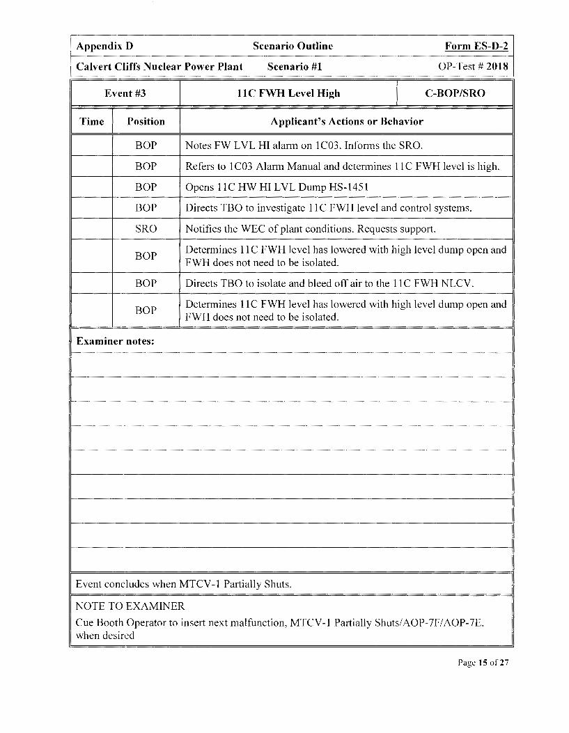
Appendix D Scenario Outline Form ES-D-2
Calvert Cliffs Nuclear Power Plant Scenario #1 OP-Test# 2018
Event #3 11 C FWH Level High I C-BOP/SRO
Time Position Applicant's Actions or Behavior
BOP Notes FW L VL HI alarm on 1 C03. Informs the SRO.
BOP Refers to 1 C03 Alarm Manual and determines I IC FWH level is high.
BOP Opens I IC HW HI LVL Dump HS-1451
BOP Directs TBO to investigate 11 C FWH level and control systems.
SRO Notifies the WEC of plant conditions. Requests support.
BOP Determines 11 C FWH level has lowered with high level dump open and FWH does not need to be isolated.
BOP Directs TBO to isolate and bleed off air to the 11 C FWH NLCV.
BOP Determines 11 C FWH level has lowered with high level dump open and FWH does not need to be isolated.
Examiner notes:
Event concludes when MTCV-1 Partially Shuts.
NOTE TO EXAMINER
Cue Booth Operator to insert next malfunction, MTCV-1 Partially Shuts/AOP-7F/AOP-7E, when desired
Page 15 of27
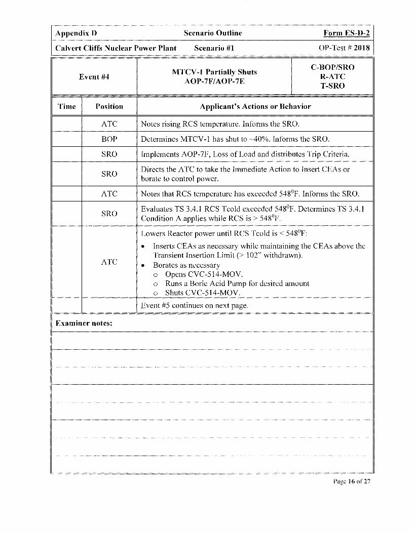
Appendix D Scenario Outline Form ES-D-2
Calvert Cliffs Nuclear Power Plant Scenario #1 OP-Test# 2018
MTCV-1 Partially Shuts C-BOP/SRO
Event #4 R-ATC AOP-7F/AOP-7E
T-SRO
Time Position Applicant's Actions or Behavior
ATC Notes rising RCS temperature. Informs the SRO.
BOP Determines MTCV-1 has shut to ~40%. Informs the SRO.
SRO Implements AOP-7F, Loss of Load and distributes Trip Criteria.
SRO Directs the A TC to take the Immediate Action to Insert CEAs or borate to control power.
ATC Notes that RCS temperature has exceeded 548°F. Informs the SRO.
SRO Evaluates TS 3.4.1 RCS Tcold exceeded 548°F. Determines TS 3.4.1 Condition A applies while RCS is> 548°F.
Lowers Reactor power until RCS Tcold is< 548°F:
• Inserts CEAs as necessary while maintaining the CEAs above the
ATC Transient Insertion Limit (> I 02" withdrawn).
• Borates as necessary 0 Opens CVC-514-MOV. 0 Runs a Boric Acid Pump for desired amount 0 Shuts CVC-514-MOV.
Event #5 continues on next page.
Examiner notes:
Page 16 of27

Appendix D Scenario Outline Form ES-D-2
Calvert Cliffs Nuclear Power Plant Scenario #1 OP-Test# 2018
MTCV-1 Partially Shuts C-BOP/SRO
Event #4 R-ATC AOP-7F/AOP-7E
T-SRO
Time Position Applicant's Actions or Behavior
ATC Verifies RCS pressure is returning to 2250 PSIA and PZR level is returning to 216".
SRO Implements AOP-7E, Main Turbine Malfunction Step XIV for Turbine Valve Failures.
SRO Notifies the WEC of plant conditions. Requests notification of the Main Turbine System Engineer and support.
BOP Adjusts TURBINE BYPASS VL V CONTR, PIC-4056, setpoint just above Main Steam header pressure but not lower than 830 PSIA.
Examiner notes:
Event concludes when MTCV-1 Fully Shuts. If SRO's understanding of the Technical Specification applicability is not clearly observable, follow-up questioning may be required upon completion of the scenario.
NOTE TO EXAMINER
Cue Booth Operator to insert next malfunction, EHC Leak/Loss of Load/ATWS/EOP-0, when desired.
Page 17 of27
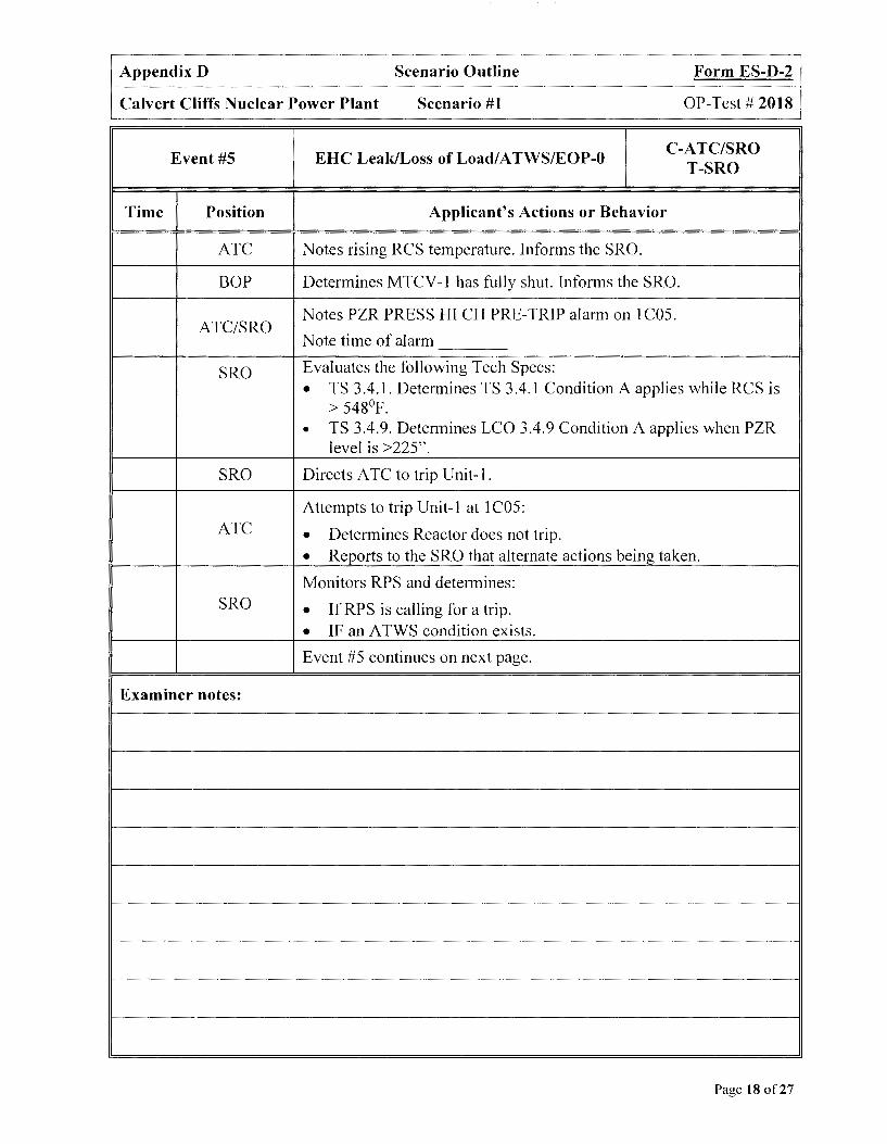
Appendix D Scenario Outline Form ES-D-2
Calvert Cliffs Nuclear Power Plant Scenario #1 OP-Test# 2018
Event #5 EHC Leak/Loss ofLoad/ATWS/EOP-0 C-ATC/SRO
T-SRO
Time Position Applicant's Actions or Behavior
ATC Notes rising RCS temperature. Informs the SRO.
BOP Determines MTCV-1 has fully shut. Informs the SRO.
Notes PZR PRESS HI CH PRE-TRIP alarm on IC05. ATC/SRO
Note time of alarm
SRO Evaluates the following Tech Specs:
• TS 3.4.1. Determines TS 3.4.1 Condition A applies while RCS is > 548°F.
• TS 3.4.9. Determines LCO 3.4.9 Condition A applies when PZR level is >225".
SRO Directs ATC to trip Unit-1.
Attempts to trip Unit-1 at I COS: ATC • Determines Reactor does not trip .
• Reports to the SRO that alternate actions being taken .
Monitors RPS and determines: SRO • If RPS is calling for a trip .
• IF an ATWS condition exists .
Event #5 continues on next page.
Examiner notes:
Page 18 of27

Appendix D Scenario Outline Form ES-D-2
Calvert Cliffs Nuclear Power Plant Scenario #1 OP-Test# 2018
Event #5
Time Position
ATC
BOP/ATC
ATC
ATC
BOP
Examiner notes:
EHC Leak/Loss of Load/ATWS/EOP-0
Determines that Reactor is tripped.
Reenergizes 12A and 13A 480V Buses:
• Shuts 12A 480V BUS FDR, 52-1201. • Shuts 13A 480V BUS FDR, 52-1301.
C-ATC/SRO T-SRO
Determines Reactivity Safety Function is met. Informs the SRO that Reactivity is complete.
Determines MSR Source MOY s, MS-4025/MS-4026, are going shut. Reports to the SRO monitoring Turbine Trip for MSR 211
d Stage Source MOVs going shut.
Event concludes when ATC begins Pressure and Inventory Control Safety Function. IfSRO's understanding of the Technical Specification applicability is not clearly observable, follow-up questioning may be required upon completion of the scenario.
NOTE TO EXAMINER
Event #6, PORV-402 Leakage, is automatically inserted when the Reactor is tripped. The Booth Operator is not required to initiate the malfunction.
Page 19 of27
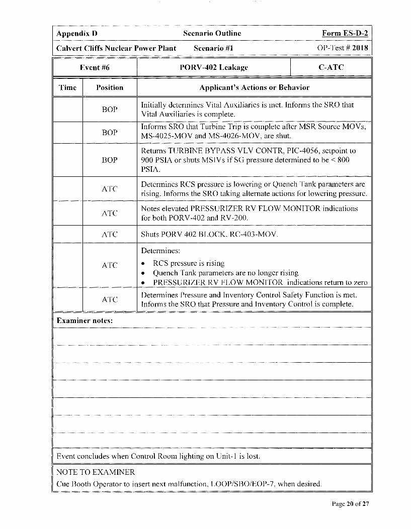
Appendix D Scenario Outline Form ES-D-2
Calvert Cliffs Nuclear Power Plant Scenario #1 OP-Test# 2018
Event #6 PORV-402 Leakage C-ATC
Time Position Applicant's Actions or Behavior
BOP Initially determines Vital Auxiliaries is met. Informs the SRO that Vital Auxiliaries is complete.
BOP Informs SRO that Turbine Trip is complete after MSR Source MOVs, MS-4025-MOV and MS-4026-MOV, are shut.
Returns TURBINE BYPASS VL V CONTR, PIC-4056, setpoint to BOP 900 PSIA or shuts MSIV s if SG pressure determined to be < 800
PSIA.
ATC Determines RCS pressure is lowering or Quench Tank parameters are rising. Informs the SRO taking alternate actions for lowering pressure.
ATC Notes elevated PRESSURIZER RV FLOW MONITOR indications for both PORV-402 and RV-200.
ATC Shuts PORV 402 BLOCK, RC-403-MOV.
Determines:
ATC • RCS pressure is rising
• Quench Tank parameters are no longer rising
• PRESSURIZER RV FLOW MONITOR indications return to zero
ATC Determines Pressure and Inventory Control Safety Function is met. Informs the SRO that Pressure and Inventory Control is complete.
Examiner notes:
Event concludes when Control Room lighting on Unit-] is Jost.
NOTE TO EXAMINER
Cue Booth Operator to insert next malfunction, LOOP/SBO/EOP-7, when desired.
Page 20 of27
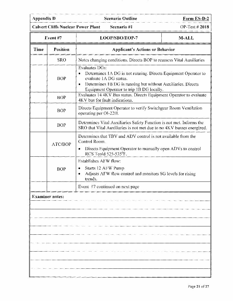
Appendix D Scenario Outline Form ES-D-2
Calvert Cliffs Nuclear Power Plant Scenario #1 OP-Test# 2018
Event #7 LOOP/SBO/EOP-7 M-ALL
Time Position Applicant's Actions or Behavior
SRO Notes changing conditions. Directs BOP to reassess Vital Auxiliaries
Evaluates DGs:
• Determines 1 A DG is not running. Directs Equipment Operator to BOP evaluate 1 A DG status.
• Determines 1 B DG is running but without Auxiliaries. Directs Equipment Operator to trip 1 B DG locally.
BOP Evaluates 14 4KV Bus status. Directs Equipment Operator to evaluate 4KV bus for fault indications.
BOP Directs Equipment Operator to verify Switchgear Room Ventilation operating per OI-22H.
BOP Determines Vital Auxiliaries Safety Function is not met. Informs the SRO that Vital Auxiliaries is not met due to no 4KV busses energized.
Determines that TBV and ADV control is not available from the
ATC/BOP Control Room.
• Directs Equipment Operator to manually open ADVs to control RCS Tcold 525-535°F.
Establishes AFW flow:
BOP • Starts 12 AFW Pump
• Adjusts AFW flow control and monitors SG levels for rising trends.
Event #7 continued on next page
Examiner notes:
Page 21 of27

Appendix D Scenario Outline Form ES-D-2
Calvert Cliffs Nuclear Power Plant Scenario #1 OP-Test# 2018
Event #7 LOOP/SBO/EOP-7 M-ALL
Time Position Applicant's Actions or Behavior
Determines Core and RCS Heat Removal Safety Function is not met. BOP Informs the SRO that Core and RCS Heat Removal is not met due to
no RCPs.
ATC/BOP Determines Containment Environment Safety Function is met. Informs the SRO that Containment Environment is complete.
Determines Radiation Levels External to Containment Safety Function ATC/BOP is not met. Informs the SRO that Radiation Levels External to
Containment is not met due to loss of power effects.
SRO Evaluates the EOP-0 flowchart and recommends the implementation of EOP-7.
SRO Directs implementation of EOP-7.
Protects the Condenser:
BOP • Verifies shut 11 and 12 MSIV .
• Verifies shut all SG BID valves .
• Places MS UPSTREAM DRN ISOL VL VS, HS-6622, in close .
Event #7 continued on next page
Examiner notes:
Page 22 of27

Appendix D Scenario Outline Form ES-D-2
Calvert Cliffs Nuclear Power Plant Scenario #1 OP-Test# 2018
Event #7 LOOP/SBO/EOP-7 M-ALL
Time Position Applicant's Actions or Behavior
Minimizes RCS Inventory Loss:
• Shuts LID CNTMT ISO valve, CVC-515-CV and CVC-516-CV .
• Shuts RCP BLEED-OFF RELIEF ISOL, CVC-505-CV and CVC-
ATC 506-CV.
• Opens 11 RCDT DRN TO CNTMT FLOOR valve, RCW-4258-SV.
• Determines Containment Sump level alarm caused by RCDT drain SV-4258 being opened.
Establishes RCS Heat Sink:
• Establishes AFW flow with 12 AFW Pump BOP • Directs an Equipment Operator to control AFW discharge pressure
locally
• Places 13 AFW Pump in Pull-To-Lock
Secures the Main Feedwater System:
• Places all COND BSTR PPs in Pull-To-Lock ATC/BOP • Places all COND PPs in Pull-To-Lock
• Places both HTR DRN PPs in Pull-To-Lock
• Directs an Equipment Operator to shut 11 B/D HX HDR ISOL valves CD-410 and CD-411
Event #7 continued on next page
Examiner notes:
Page 23 of27
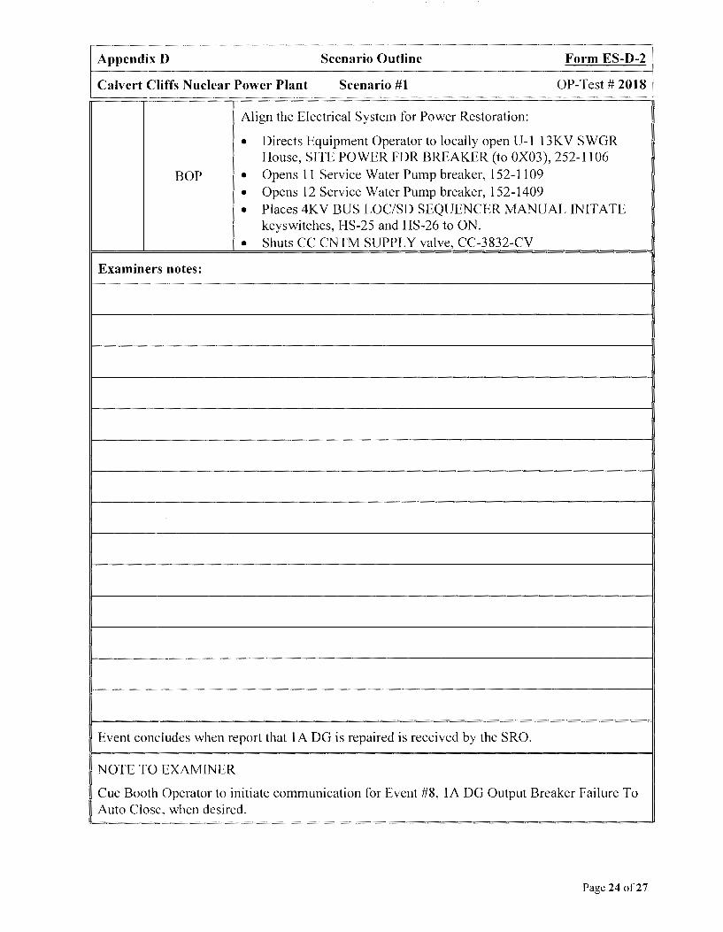
Appendix D Scenario Outline Form ES-D-2
Calvert Cliffs Nuclear Power Plant Scenario #1 OP-Test# 2018
Align the Electrical System for Power Restoration:
• Directs Equipment Operator to locally open U-1 13KV SWGR House, SITE POWER FDR BREAKER (to OX03), 252-1106
BOP • Opens 11 Service Water Pump breaker, 152-1109
• Opens 12 Service Water Pump breaker, 152-1409
• Places 4KV BUS LOC/SD SEQUENCER MANUAL INITATE keyswitches, HS-25 and HS-26 to ON.
• Shuts CC CNTM SUPPLY valve, CC-3832-CV
Examiners notes:
Event concludes when report that 1 A DG is repaired is received by the SRO.
NOTE TO EXAMINER
Cue Booth Operator to initiate communication for Event #8, IA DG Output Breaker Failure To Auto Close, when desired.
Page 24 of27

Appendix D Scenario Outline Form ES-D-2
Calvert Cliffs Nuclear Power Plant Scenario #1 OP-Test# 2018
Time Position
BOP
BOP
BOP
BOP
Examiner's notes:
lA DG Output Breaker Failure to Auto Close
Applicant's Actions or Behavior
C-ATC
Directs Equipment Operator to start IA DG per Restart of IA DG with an Automatic Start Signal Present section of 0I-21A.
Notes that IA DG is running but output breaker has not auto closed.
Manually closes DG OUT BKR, 152-1703.
The scenario wi11 terminate when the Critical Tasks for tripping the Reactor and restoring power to the 11 4KV bus are completed.
After scenario ends ask SRO for ERPIP call. The correct Emergency Action Level declaration for this scenario is:
Site Area Emergency, per SS 1.1, in Event 7, due to Loss of all onsite and off site AC power, Table S-1, 10 4KV vital buses 11 (21) and 14(24) for :::,15 mins
Page 25 of27
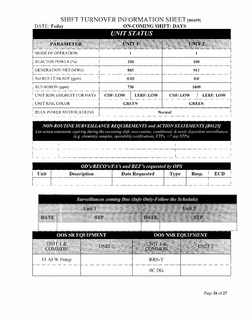
SHIFT TURNOVER INFORMATION SHEET IB0459J
DA TE: Today ON-COMING SHIFT: DAYS
MODE OF OPERATION
REACTOR POWER(%) 100 100
GENERATION NET (MWe) 885 912
Net RCS LEAKAGE (gpm) 0.03 0.0
RCS BORON (ppm) 756 1609 ---------------------+-------~---------1
UNIT RISK (HIGHEST FOR DAY) CDF: LOW LERF: LOW CDF: LOW LERF: LOW
UNIT RISK COLOR GREEN GREEN
BULK POWER NOTIFICATIONS Normal
NON-ROUTINE SURVEILLANCE REQUIREMENTS mul ACTION STATEMENTS [B0125] List action statements expiring during the oncoming shift, non-routine, conditional, & mode dependent surveillances
(e.g. chemishy samples, operability verifications, ETPs, <7 day STP!>)
OD's!RECO's!FA 'sand REF's requeste,l by OPS
Unit Description Date Requested Type Resp. ECD
11 AFW Pump RRS-Y
OCDG
Page 26 of27

LONG TERM NOTES
I. None
SHORT TERM NOTES
32.5 psig (yesterday) 30 psig (yesterday)
1. Vibrations on 11 EHC Pump are elevated. Component Monitoring requests shift to 12 EHC Pump immediately after taking the watch. When shifting, place Filter 1 in service on 12 EHC Pump.
2. RCS sulfates are elevated and Chemistry requests maximum purification. Chemistry evaluating IX DIP trend and plans to reload another IX as a purification bed.
3. 12 Charging Pump packing leakage developed on last shift and is primary source of net RCS leakage. If Charging Pumps need swapped, ensure 12 Charging Pump is secured.
Page 27 of27

Appendix D Scenario Outline Form ES-D-1
Calvert Cliffs Nuclear Power Plant Scenario #2 OP-Test# 2018
Examiners: Operators:
Initial Conditions: U-1 is at 100% power, MOC. U-2 is at 100%.
Turnover: Condensate Demin Bypass MOV, RRS-Y, and OC DG OOS. The crew is instructed to complete STP 0-70-1 on 11 Pene Room Ventilation Fan.
Critical Tasks
I. Establishes AFW flow to at least one S/G at :::_150 GPM prior to S/G levels going below (-) 350 inches.
2. Initiates an RCS Cooldown without exceeding 100°F in one hour. (Applicable only if OTCC is not initiated)
3. Commences OTCC when both S/G levels are below(-) 350 inches or TCOLD rises uncontrollably 5 °F or greater. (Applicable only if SG levels lower below (-)350 inches)
Event# Malfunction # Event Type* Event Description
I N-BOP/SRO 11 Pene Room Fan Test/STP 0-70-1
2 P1Cl8 F12 C-ATC VCT Pressure High
3 cd009 02 C-BOP/SRO
Condenser Tube leak/AOP-10 cdOOl R-ATC
4 cd009 02 C-ALL 2nd Condenser Tube Leak/EOP-0/EOP-1
5 rcs026 02 I-ATC
LT-IOOY Fails High T-SRO
6 afw005 C-BOP/SRO 13 AFW Pump Trip/Steam Driven AFW Steam
afwOOI 01 T-SRO Leak
7 afw005
M-ALL Loss of All Feedwater/EOP-3 afw001 01
* (N)ormal (R)eactivity (I)nstrument (C)omponent (M)ajor (T)ech Spec
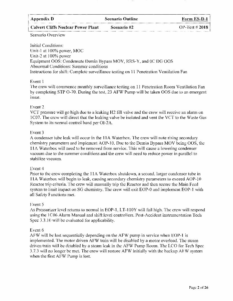
Appendix D Scenario Outline
Calvert Cliffs Nuclear Power Plant Scenario #2
Scenario Overview
Initial Conditions: Unit-I at l 00% power, MOC Unit-2 at l 00% power Equipment OOS: Condensate Demin Bypass MOV, RRS-Y, and OC DG OOS Abnormal Conditions: Summer conditions
Form ES-D-1
OP-Test# 2018
Instructions for shift: Complete surveillance testing on 11 Penetration Ventilation Fan
Event 1 The crew will commence monthly surveillance testing on 11 Penetration Room Ventilation Fan by completing STP 0-70. During the test, 23 AFW Pump will be taken OOS due to an emergent issue.
Event 2 VCT pressure will go high due to a leaking H2 fill valve and the crew will receive an alarm on 1 C07. The crew will direct that the leaking valve be isolated and vent the VCT to the Waste Gas System to its normal control band per 0I-2A.
Event 3 A condenser tube leak will occur in the 1 lA Waterbox. The crew will note rising secondary chemistry parameters and implement AOP-10. Due to the Demin Bypass MOV being OOS, the 11 A Waterbox will need to be removed from service. This will cause a lowering condenser vacuum due to the summer conditions and the crew will need to reduce power in parallel to stabilize vacuum.
Event 4 Prior to the crew completing the 1 lA Waterbox shutdown, a second, larger condenser tube in 11 A Water box will begin to leak, causing secondary chemistry parameters to exceed AOP-10 Reactor trip criteria. The crew will manually trip the Reactor and then secure the Main Feed system to limit impact on SG chemistry. The crew will exit EOP-0 and implement EOP-1 with all Safety Functions met.
Event 5 As Pressurizer level returns to normal in EOP-1, L T-11 OY will fail high. The crew will respond using the 1 C06 Alarm Manual and shift level controllers. Post-Accident instrumentation Tech Spec 3.3.10 will be evaluated for applicability.
Event 6 AFW will be lost sequentially depending on the AFW pump in service when EOP-1 is implemented. The motor driven AFW train will be disabled by a motor overload. The steam driven train will be disabled by a steam leak in the AFW Pump Room. The LCO for Tech Spec 3.7.3 will no longer be met. The crew will restore AFW initially with the backup AFW system when the first AFW Pump is lost.
Page 2 of26

Appendix D Scenario Outline Form ES-D-1
Calvert Cliffs Nuclear Power Plant Scenario #2 OP-Test# 2018
Event 7 The last remaining Unit- I AFW Pump will be lost and the crew will identify the loss of all feedwater. EOP-1 Safety Functions will no longer be met and the crew will exit EOP-1 and implement EOP-3. The crew will trip all RCPs and commence RCS boration. A rapid cooldown will be started and the crew will demonstrate the Critical Task of maintaining the cool down less than I 00°F in one hour. Once the cooldown is started, 23 AFW Pump will become available. The crew will restore SG levels by using the Unit-2 motor driven AFW Pump to restore feedwater on Unit-1. Once AFW is restored, the crew will slow the cooldown rate and stabilize the plant in Mode 3 to satisfy the Critical Task of maintaining RCS cooldown rates within Tech Spec limits. If SG levels lower< -350", then the crew will perform the potential critical task of initiating OTCC.
If plant conditions degrade or the crew is unsure of the diagnosis it is acceptable for them to enter EOP-8 instead of EOP-3. If EOP-8 is entered, all critical tasks still apply unless individual tasks are invalidated by the exam team.
Page 3 of26

Appendix D Scenario Outline Form ES-D-1
Calvert Cliffs Nuclear Power Plant Scenario #2 OP-Test# 2018
Scenario Setup Instructions
1. Reset to IC-34.
2. Place simulator in RUN and advance charts.
3. Place simulator in FREEZE.
4. Enter Triggers:
a. CEA on bottom (1 YlO required) to Event 6
b. CEA on bottom (1 YlO required) to Event 8
5. Enter Malfunctions:
a. dg002_01
b. afw004 01
c. afw004 02
d. cdOOl from 2.0 to 0.10000 in 300 on event 19
e. rcs026 02 to 1 HIGH on event 5 - -
f. afa 005 on event 17
6. Enter Remote Functions:
a. EPOOl to 90.0
b. EP002 to 70.0
C. O-N2-250 to 0.1 on event 2
d. O-N2-250 to 0.02 on event 16
e. O-N2-250 to 0.0 on event 15
f. l-MS-3986 after 10 to O in 30 on event 18
g. l-MS-3988 after 10 to O in 30 on event 18
Page 4 of26
Appendix D Scenario Outline
Calvert Cliffs Nuclear Power Plant Scenario #2
7. Enter Panel Overrides:
a. Pl C03 1HS4439 to OPEN
b. P1C03 1MOV4439 LTRED to Off - -
c. P1C03 1HS4439 LTWHIT to Off - -
d. Pl Cl 7 L14 LTON to Off on event 2 - -
e. P1C33 T13 LTON to Off on event 2 - -
f. P1C03 C52 LTON to On on event 3 - -
g. P1C03_C2I_LTON after 30 to On on event 3
h. P 1 C 1 7 L 11 L TON after 120 to On on event 3 - -
1. P 1 C 10 120 L TON to On on event 18
J. P1C04 1PI3987 MT from 1100.0 to O in 60 on event 18
k. P1C04 1PI3989 MT from 1100.0 to O in 60 on event 18 - -
I. Pl C04 W05 LTON to Off on event 18 - -
m. P1C04 1STP3986 LTRED to Off on event 18 - -
n. P1C04 1STP3986 LTWHI to On on event 18 - -
o. P1C04 1HS4550 to OPEN on event 14
p. 2-HS-4540 to START on event 13
8. Administrative:
a. Place an "INFO" tag on Condensate Demin Bypass MOV.
b. Place an off normal tag on RRS-Y.
c. Verify PRZR LVL CH SEL switch, 1-HS-110, is selected to 1 lOY.
d. Think Reactivity tag moved to l-HS-110.
e. Raise VCT pressure to -40 PSIG per 0I-2A, using remote N2-250.
f. Place OC DG Output breaker in Pull To Lock.
Form ES-D-1
OP-Test# 2018
g. Place "INFO" tags on OC DG Output Breaker, OC Emergency Start, and OC Slow Start push buttons.
h. STP 0-70-1 marked with Step 6.4.1 complete and SM/SRO approval signatures.
1. Reset/ Acknowledge panel and PPC alarms.
J. Cycle 11 Pene Room Filter Damper HS-5285 shut and then open to get alarms on PPC.
k. Verify adequate copies of AOP-10.
I. Ensure correct magnetic plaques are in place.
Page 5 of26

Appendix D Scenario Outline Form ES-D-1
Calvert Cliffs Nuclear Power Plant Scenario #2 OP-Test# 2018
9. Independently verify correct completion of the following:
a. Event Triggers correctly entered
b. Malfunctions correctly entered
c. Remote Functions correctly entered
d. Panel Overrides correctly entered
e. Administrative actions correctly performed
10. Place simulator in RUN.
11. Ensure schedule files are in RUN.
12. Ensure Trigger files are in RUN.
13. Ensure all PPC screens selected to Main Menu, Alarms, or SPDS Operating Summary page.
14. Select ·'Clock" and ensure "Hom On" for annunciators.
15. Brief the Crew:
1. Present plant conditions: Both Units are at 100% power
Unit-I is in MOC
2. Power history: Unit- I has been at 100% for last 3 months
RRS-Y
3. Equipment out of service: OCDG
Condensate Demin Bypass MO V
4. Abnormal conditions: Summer conditions
5. Surveillances due: STP 0-70-1 due today.
6. Instructions for shift: Complete STP 0-70-1. First step to perform is 6.4, which will test the 11 Penetration Room Vent Fan.
16. Allow crew 3-5 minutes to acclimate themselves with their positions.
Page 6 of26

Appendix D Scenario Outline Form ES-D-1
Calvert Cliffs Nuclear Power Plant Scenario #2 OP-Test# 2018
17. Instructions for the Booth Operator:
a. Event 1: When directed by Lead Examiner, call into Control Room as ABO and report "I'm on station and ready for STP 0-70."
b. Event 2: Activate VCT Pressure High when directed by the Lead Examiner. When VCT pressure alarms, immediately initiate Director Event 16.
c. Event 3: Activate Condenser Tube leak/AOP-10 when directed by the Lead Examiner.
d. Event 4: When directed by Lead Examiner, call into Control Room as Chemistry and report "Both Condensate and Feedwater Sodium are 220 PPB and stable."
e. Ev~nt 5: Activate LT-IOOY Fails High when directed by Lead Examiner.
f. Ewnt 6: When directed by Lead Examiner, activate trip of running AFW Pump:
1) If 13 AFW Pump is running, initiate Director Event 17.
2) If 12 AFW Pump is running, initiate Director Event 18 Trip/Steam Driven AFW Steam Leak
g. Event 7: When directed by Lead Examiner, activate trip ofremaining AFW Pump:
1) If 13 AFW Pump is running, initiate Director Event 17.
2) If 12 AFW Pump is running, initiate Director Event 18 Trip/Steam Driven AFW Steam Leak.
3) Call into the Control Room with the following reports once EOP-3 is implemented and the RCPs are secured:
a. If SG level is> (-) 170" report "23 AFW Pump return to service is imminent."
b. If SG level is < (-) 170" report "23 AFW Pump has been returned to service and is available."
Page 7 of26

Appendix D Scenario Outline Form ES-D-1
Calvert Cliffs Nuclear Power Plant Scenario #2 OP-Test# 2018
Responses to Crew Requests
If a request and response is not listed, delay the response until reviewed with the examiner. If one request is dependent upon completion of another, then subsequent actions should not be responded to until the appropriate time delay has been observed. Responses to routine requests, which have no effect the scenario, do not require examiner clearance.
Allow 2-3 minutes to perform requests from or to give reports to the Control Room unless otherwise specified.
l,'';i~)ii;.·· REQUEST RESPONSE
;.t ; .. ·J; . .· '.t ,-. ~ ,_{'
Event 1-11 Pene Room Fan Test/STP 0-70-1
1. WEC informed of issue/status. Acknowledge request. No further actions required.
2. Locally verify that 11 Ventilation Fan Acknowledge request.
discharge damper opens. • After 1 minute report "1-HVAC-5283 is open locally."
Acknowledge request.
• After 1 minute report "l-PDI-5285 DIP is 0.2 inches water and 1-PDIS-5285
3. 11 Penetration Room HEP A and Charcoal DIP is 0.4 inches water." Filter D/Ps. • After 1 more minute, call the Unit
Supervisor and report "23 AFW Pump has been taken OOS due to an emergent breaker issue."
4. Secure Zinc Addition Skid. Acknowledge request. No further actions required.
Event 2- VCT Pressure High
1. WEC informed of issue/status. Acknowledge request. No further actions required.
Acknowledge request.
After 1 minute, report "There's a Condition report that 1-CVC-190 leaks by when shut
2. Investigate VCT conditions locally. and I found l-CVC-189, which should be shut, cracked open. I can hear H2 gas flow right now. Want me to shut 1-CVC-189, which should be shut right now?"
Acknowledge request and immediately
3. Shut 1-CVC-189. modify
After I minute, report "l-CVC-189 is shut and I do not hear any additional gas flow."
Page 8 of26
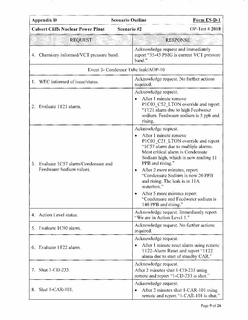
Appendix D Scenario Outline Form ES-D-1
Calvert Cliffs Nuclear Power Plant Scenario #2 OP-Test# 2018
REQUEST RESPONSE
Acknowledge request and immediately 4. Chemistry informed/VCT pressure band. report "35-45 PSIG is current VCT pressure
band."
Event 3- Condenser Tube leak/AOP-10
1. WEC informed of issue/status. Acknowledge request. No further actions required.
Acknowledge request.
• After 1 minute remove
2. Evaluate 1 T21 alarm. P 1 C03 _ C52_ L TON override and report "1 T2 l alarm due to high F eedwater sodium. Feedwater sodium is 5 ppb and .. nsmg.
Acknowledge request.
• After 1 minute remove P 1 C03 _ C21 _ L TON override and report "1 C57 alarm due to multiple alarms. Most critical alarm is Condensate Sodium high, which is now reading 11
3. Evaluate 1 C57 alarm/Condensate and PPB and rising." Feedwater Sodium values. • After 2 more minutes, report
"Condensate Sodium is now 20 PPB and rising. The leak is in 11 A water box."
• After 5 more minutes report "Condensate and Feedwater sodium is 140 PPB and rising."
4. Action Level status. Acknowledge request. Immediately report "We are in Action Level 1."
5. Evaluate 1 C90 alarm. Acknowledge request. No further actions required.
Acknowledge request.
6. Evaluate 1 T22 alarm. • After 1 minute reset alarm using remote 1 T22-Alarm Reset and report "1 T22 alarm due to start of standby CAR."
Acknowledge request. 7. Shut 1-CD-233. After 2 minutes shut 1-CD-233 using
remote and report "l-CD-233 is shut."
Acknowledge request. 8. Shut 1-CAR-101. • After 2 minutes shut 1-CAR-101 using
remote and report "l-CAR-101 is shut."
Page 9 of26

Appendix D Scenario Outline Form ES-D-1
Calvert Cliffs Nuclear Power Plant Scenario #2 OP-Test# 2018
Acknowledge request.
• After 2 minutes, place l-CW-5225-HS 9. Shut 1 lA Waterbox Inlet MOY. in CLOSED using remote.
• After 1 more minute report "11 A Inlet Waterbox MOY-5225 is shut."
10. Secure Chem Add injection. Acknowledge request. No further actions required.
Acknowledge request. Immediately report "The Condensate Demins cannot be placed
11. Status of Condensate Demin Bypass MOY. in service at this time and it may be at least another 30 minutes before the maintenance is completed on the Demin Bypass MOY."
12. Place Condensate Demins in service. Acknowledge request. No further actions required.
13. Maximize SG Blowdown. Acknowledge request. No further actions required.
Event 4-2 11d Condenser Tube Leak/EOP-0/EOP-1
Acknowledge request. Immediately report
1. Condensate and Feedwater Sodium values. Condensate and Feedwater sodium are 220 PPB and steady. Leak has stopped now that 11 A water box is secured."
Event 5-LT-lOOY Fails High
1. WEC informed of issue/status. Acknowledge request. No further actions required.
Event 6-13 AFW Pump Trip/Steam Driven AFW Steam Leak
Acknowledge request.
1. Evaluate 13 AFW Pump status. • If originally running in EOP-1, wait 1 minute and then report "13 AFW Pump breaker has tripped on overload."
Acknowledge request.
• If originally running in EOP-1, wait 1
2. Evaluate 11 AFW Pump status. minute and then report "AFW Room Watertight door is hot to the touch and it sounds like I hear steam flow in the room."
Acknowledge request.
3. AFW Pump Room Steam Leak status. • If MS-4070/4071 are shut, wait 1 minute ad report "AFW Room Watertight door is still hot to the touch
Page 10 of26
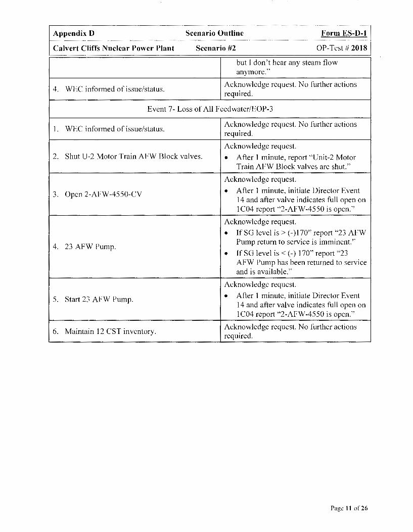
Appendix D Scenario Outline Form ES-D-1
Calvert Cliffs Nuclear Power Plant Scenario #2 OP-Test# 2018
but I don't hear any steam flow anymore."
4. WEC informed of issue/status. Acknowledge request. No further actions required.
Event 7- Loss of All Feedwater/EOP-3
1. WEC informed of issue/status. Acknowledge request. No further actions required.
Acknowledge request. 2. Shut U-2 Motor Train AFW Block valves. • After 1 minute, report "Unit-2 Motor
Train AFW Block valves are shut."
Acknowledge request.
3. Open 2-AFW-4550-CV • After 1 minute, initiate Director Event 14 and after valve indicates full open on 1C04 report "2-AFW-4550 is open."
Acknowledge request.
• If SG level is > ( -) 170" report "23 AFW
4. 23 AFW Pump. Pump return to service is imminent."
• If SG level is < (-) 170" report "23 AFW Pump has been returned to service and is available."
Acknowledge request.
5. Start 23 AFW Pump. • After 1 minute, initiate Director Event 14 and after valve indicates full open on 1 C04 report "2-AFW-4550 is open."
6. Maintain 12 CST inventory. Acknowledge request. No further actions required.
Page 11 of26
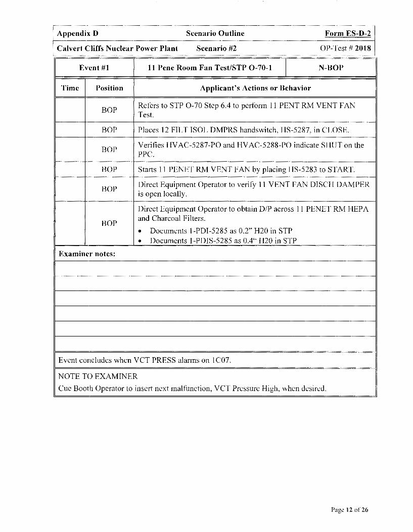
Appendix D Scenario Outline Form ES-D-2
Calvert Cliffs Nuclear Power Plant Scenario #2 OP-Test# 2018
Event #1 11 Pene Room Fan Test/STP 0-70-1 I N-BOP
Time Position Applicant's Actions or Behavior
BOP Refers to STP 0-70 Step 6.4 to perform 11 PENT RM VENT FAN Test.
BOP Places 12 FILT ISOL DMPRS handswitch, HS-5287, in CLOSE.
BOP Verifies HVAC-5287-PO and HVAC-5288-PO indicate SHUT on the PPC.
BOP Starts 11 PENET RM VENT FAN by placing HS-5283 to START.
BOP Direct Equipment Operator to verify 11 VENT FAN DISCH DAMPER is open locally.
Direct Equipment Operator to obtain DIP across 11 PENET RM HEP A
BOP and Charcoal Filters.
• Documents 1-PDI-5285 as 0.2" H20 in STP
• Documents 1-PDIS-5285 as 0.4" H20 in STP
Examiner notes:
Event concludes when VCT PRESS alarms on 1 C07.
NOTE TO EXAMINER
Cue Booth Operator to insert next malfunction, VCT Pressure High, when desired.
Page 12 of26

Appendix D Scenario Outline Form ES-D-2
Calvert Cliffs Nuclear Power Plant Scenario #2 OP-Test# 2018
Event #2 VCT Pressure High I C-ATC
Time Position Applicant's Actions or Behavior
ATC Notes VCT PRESS alarm on 1 C07. Informs SRO.
ATC Refers to 1 C07 Alarm Manual and determines VCT pressure is high.
ATC Directs Equipment Operator to verify VCT hydrogen or nitrogen charging is not in progress.
ATC Refers to OI-2A Step 6.5 to vent the VCT.
ATC/SRO Notifies Radiation Safety of venting the VCT.
ATC Places VCT VENT, CVC-513-CV, to OPEN.
ATC When VCT pressure is restored to 35-45 PSIG, places VCT VENT, CVC-513-CV, to CLOSE.
Examiner notes:
J Event concludes when 11 TURB PLANT SMPL SYS 1T21 alarms on 1C03.
NOTE TO EXAMINER
Cue Booth Operator to insert next malfunction, Condenser Tube leak/ AOP-10, when desired.
Page 13 of26
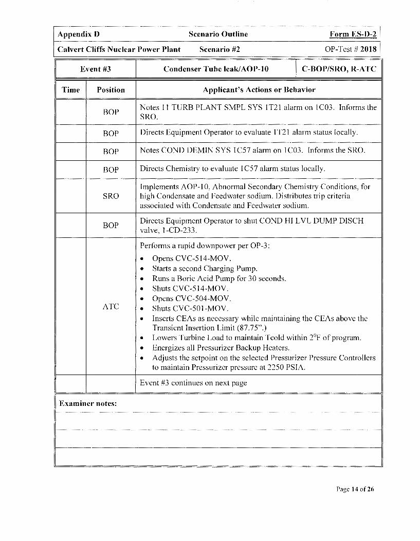
Appendix D Scenario Outline Form ES-D-2
Calvert Cliffs Nuclear Power Plant Scenario #2 OP-Test# 2018
Event #3 Condenser Tube leak/AOP-10 I C-BOP/SRO, R-ATC
Time Position Applicant's Actions or Behavior
BOP Notes 11 TURB PLANT SMPL SYS 1T21 alarm on 1C03. Informs the SRO.
BOP Directs Equipment Operator to evaluate 1 T2 l alarm status locally.
BOP Notes COND DEMIN SYS 1 C57 alarm on 1 C03. Informs the SRO.
BOP Directs Chemistry to evaluate 1 C57 alarm status locally.
Implements AOP-10, Abnormal Secondary Chemistry Conditions, for SRO high Condensate and Feedwater sodium. Distributes trip criteria
associated with Condensate and Feedwater sodium.
BOP Directs Equipment Operator to shut COND HI LVL DUMP DISCH valve, l-CD-233.
Performs a rapid downpower per OP-3:
• Opens CVC-514-MOV .
• Starts a second Charging Pump .
• Runs a Boric Acid Pump for 30 seconds .
• Shuts CVC-514-MOV .
• Opens CVC-504-MOV . ATC • Shuts CVC-501-MOV .
• Inserts CEAs as necessary while maintaining the CEAs above the Transient Insertion Limit (87.75".)
• Lowers Turbine Load to maintain Tcold within 2°F of program .
• Energizes all Pressurizer Backup Heaters .
• Adjusts the setpoint on the selected Pressurizer Pressure Controllers to maintain Pressurizer pressure at 2250 PSIA.
Event #3 continues on next page
Examiner notes:
Page 14 of26

Appendix D Scenario Outline Form ES-D-2
Calvert Cliffs Nuclear Power Plant Scenario #2 OP-Test# 2018
Event #3 Condenser Tube leak/AOP-10 I C-BOP/SRO, R-A TC
Time Position Applicant's Actions or Behavior
BOP Places CNDSR HOTWELL M/U and DUMP CONTR, LIC-4405, in MANUAL.
BOP Places 1 lA PRIMING VLV, WBP-1746-CV, in CLOSE.
BOP Stops 11 Circulating Water Pump.
BOP Directs Equipment Operator to shut IA CAR COND SHELL STOP valve, CAR-101.
BOP Breaks vacuum in 1 lA Waterbox by placing l lA WATERBOX VAC BKR VALVE, CW-5228-CV, in OPEN.
SRO Notifies the WEC of plant conditions. Requests support.
Examiner notes:
Event concludes when Chemistry reports Condensate and Feed water sodium are> 200 PPB.
NOTE TO EXAMINER
Cue Booth Operator to report Condensate and Feedwater values> 200 PPB to initiate next malfunction, 2nd Condenser Tube Leak/EOP-O/EOP-1, when desired.
Page 15 of26

Appendix D Scenario Outline Form ES-D-2
Calvert Cliffs Nuclear Power Plant Scenario #2 OP-Test# 2018
Event #4 2nd Condenser Tube Leak/EOP-0/EOP-1 I C-ALL
Time Position Applicant's Actions or Behavior
BOP/SRO Determines trip criteria has been exceeded for Condensate and Feedwater sodium.
SRO Directs A TC to trip Unit-I.
ATC Trips Unit-I Reactor.
SRO Implements EOP-0.
ATC Determines Reactivity Safety Function is met. Informs the SRO that Reactivity is complete.
May secure from the rapid downpower per OP-3: ATC • Opens CVC-501-MOV
• Shuts CVC-504-MOV After Reactivity is reported or the Reactor is tripped, directs BOP to
SRO take following actions per AOP-10:
• Initiate AFW
• Trip both SGFPs
Starts AFW by either:
BOP • Starts 13 AFW Pump or
• Starts 11 AFW Pump by opening MS-4070/4070A-CV and MS-4071/4071A-CV
BOP Trips 11 and 12 SGFPs.
Event #4 continues on next page
Examiner notes:
Page 16 of26

Appendix D Scenario Outline Form ES-D-2
Calvert Cliffs Nuclear Power Plant Scenario #2 OP-Test# 2018
Event #4 2nd Condenser Tube Leak/EOP-0/EOP-1 C-ALL
Time Position Applicant's Actions or Behavior
Determines MSR Source MOVs, MS-4025/MS-4026, are going shut.
BOP Reports to the SRO monitoring Turbine Trip for MSR 2nd Stage Source MOVs going shut.
BOP Initially determines Vital Auxiliaries is met. Informs the SRO that Vital Auxiliaries is complete.
ATC Determines Pressure and Inventory Control Safety Function is met. Informs the SRO that Pressure and Inventory Control is complete.
BOP Informs SRO that Turbine Trip is complete after MSR Source MOVs, MS-4025-MOV and MS-4026-MOV, are shut.
BOP May monitor Core and RCS Heat Removal Safety Function for SG level trends.
BOP Determines Core and RCS Heat Removal Safety Function is met. Informs the SRO that Core and RCS Heat Removal is complete.
ATC/BOP Determines Containment Environment Safety Function is met. Informs the SRO that Containment Environment is complete.
Determines Radiation Levels External to Containment Safety ATC/BOP Function is met. Informs the SRO that Radiation Levels External to
Containment is complete.
SRO Evaluates the EOP-0 flowchart and recommends the implementation ofEOP-1.
SRO Directs implementation of EOP-1.
Examiner notes:
Event concludes when Restore Normal Pressurizer Level is assigned in EOP-1.
NOTE TO EXAMINER
Cue Booth Operator to insert next malfunction. LT-IOOY Fails High, when desired.
Page 17 of26

Appendix D Scenario Outline Form ES-D-2
Calvert Cliffs Nuclear Power Plant Scenario #2 OP-Test# 2018
Event #5 LT-lOOY Fails High I-ATC, T-SRO
Time Position I Applicant's Actions or Behavior
ATC Notes PZR CH Y L VL alarm on 1 C06.
ATC Determines L T-11 OY or LIC-1 IOY has failed high. Informs the SRO.
ATC Shifts PZR L VL CH SEL switch, HS-110, to 11 OX.
ATC Shifts PZR HTR LO LVL CUT-OFF SEL switch, HS-100-3, to X.
ATC Determines PZR level is trending to 160".
SRO Evaluates Tech Spec 3.3.10. Determines 3.3.10 Condition A applies.
Secures the Main Feedwater system:
• Places all Condensate Booster Pumps in PULL TO LOCK . BOP • Places one Condensate Pump in PULL TO LOCK .
• Places both Heater Drain Pumps in PULL TO LOCK .
• Shuts FW-4516-MOV and FW-4517-MOV .
Examiner notes:
1 .:::::v..,11t concludes when first AFW Pump trips.
NOTE TO EXAMINER
Cue Booth Operator to insert next malfunction, 13 AFW Pump Trip/Steam Driven AFW Steam Leak, when desired.
Page 18 of26

Appendix D Scenario Outline Form ES-D-2
Calvert Cliffs Nuclear Power Plant Scenario #2 OP-Test# 2018
Event #6 13 AFW Pump Trip
C-BOP, T-SRO Steam Driven AFW Steam Leak
Time Position Applicant's Actions or Behavior
BOP/SRO Determines the running AFW pump has tripped. Informs the SRO.
BOP/SRO Notes U-1 4KV ESF MOTOR OVERLOAD alarm on 1C18. Informs the SRO. (NIA if 11 AFW Pump was initially running)
BOP Determines 13 AFW Pump has tripped. (NI A if 11 AFW Pump was initially running)
BOP/SRO Notes AFW PP RM TEMP/SUMP LVL HI alarm on lClO. Informs the SRO. (NIA if 13 AFW Pump was initially running)
BOP Directs Equipment Operator to evaluate AFW Pump Room conditions. (NI A if 13 AFW Pump was initially running)
BOP Notes loss of all Feed water.
SRO Determines Core and RCS Heat Removal Safety Function is no longer being met due to loss of all feed.
Event #6 continues on next page.
Examiner notes:
Page 19 of26
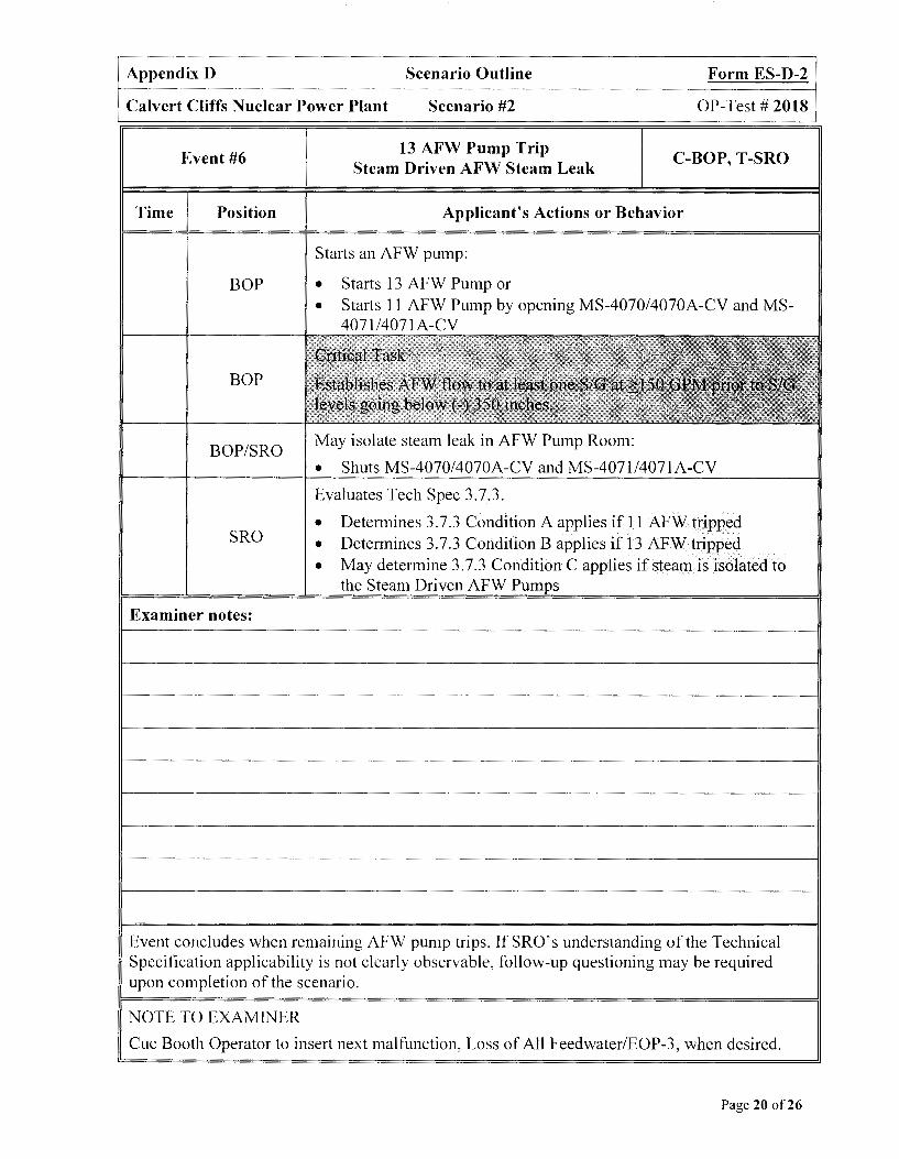
Appendix D Scenario Outline Form ES-D-2
Calvert Cliffs Nuclear Power Plant Scenario #2 OP-Test# 2018
Event #6
Time Position
BOP
BOP
BOP/SRO
SRO
Examiner notes:
13 AFW Pump Trip Steam Driven AFW Steam Leak
C-BOP, T-SRO
Applicant's Actions or Behavior
Starts an AFW pump:
• Starts 13 AFW Pump or • Starts 11 AFW Pump by opening MS-4070/4070A-CV and MS-
4071/4071 A-CV
May isolate steam leak in AFW Pump Room:
• Shuts MS-4070/4070A-CV and MS-4071/4071A-CV
Evaluates Tech Spec 3.7.3.
• Determines 3. 7 .3 Condition A applies if 11 AFW tripped • Determines 3. 7 .3 Condition B applies if 13 AFW tripped • May determine 3. 7 .3 Condition C applies if steam is isolated to
the Steam Driven AFW Pumps
Event concludes when remaining AFW pump trips. If SRO's understanding of the Technical Specification applicability is not clearly observable, follow-up questioning may be required upon completion of the scenario.
NOTE TO EXAMINER
Cue Booth Operator to insert next malfunction, Loss of All Feedwater/EOP-3, when desired.
Page 20 of26
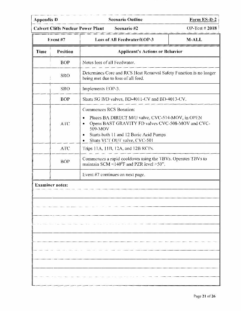
Appendix D Scenario Outline Form ES-D-2
Calvert Cliffs Nuclear Power Plant Scenario #2 OP-Test# 2018
Event #7 Loss of All FeedwaterlEOP-3 M-ALL
Time Position Applicant's Actions or Behavior
: BOP Notes loss of all Feedwater.
SRO Determines Core and RCS Heat Removal Safety Function is no longer being met due to loss of all feed.
SRO Implements EOP-3.
BOP Shuts SG BID valves, BD-4011-CV and BD-4013-CV.
Commences RCS Boration:
• Places BA DIRECT MIU valve, CVC-514-MOV, in OPEN ATC • Opens BAST GRAVITY FD valves CVC-508-MOV and CVC-
509-MOV
• Starts both 11 and 12 Boric Acid Pumps
• Shuts VCT OUT valve, CVC-501
ATC Trips 11 A, 11 B, 12A, and l 2B RCPs.
BOP Commences a rapid cooldown using the TBVs. Operates TBVs to maintain SCM <140°F and PZR level >50".
Event #7 continues on next page.
Examiner notes:
Page 21 of26
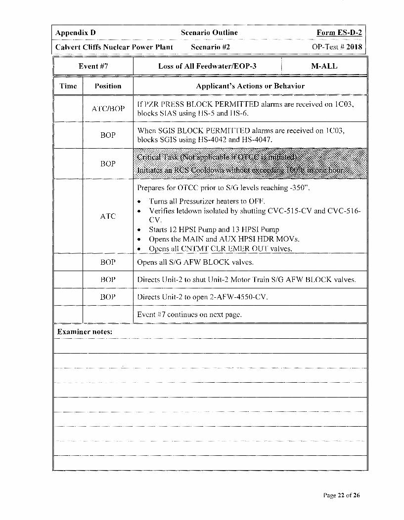
Appendix D Scenario Outline Form ES-D-2
Calvert Cliffs Nuclear Power Plant Scenario #2 OP-Test# 2018
Event #7
Time Position
ATC/BOP
BOP
BOP
ATC
BOP
BOP
BOP
Examiner notes:
Loss of All Feedwater/EOP-3 M-ALL
Applicant's Actions or Behavior
If PZR PRESS BLOCK PERMITTED alarms are received on 1 C03, blocks SIAS using HS-5 and HS-6.
When SGIS BLOCK PERMITTED alarms are received on 1 C03, blocks SGIS using HS-4042 and HS-4047.
j!lf Prepares for OTCC prior to SIG levels reaching -350".
• Turns all Pressurizer heaters to OFF. • Verifies letdown isolated by shutting CVC-515-CV and CVC-516-
CV. • Starts 12 HPSI Pump and 13 HPSI Pump • Opens the MAIN and AUX HPSI HDR MOVs. • Opens all CNTMT CLR EMER OUT valves.
Opens all SIG AFW BLOCK valves.
Directs Unit-2 to shut Unit-2 Motor Train SIG AFW BLOCK valves.
Directs Unit-2 to open 2-AFW-4550-CV.
Event #7 continues on next page.
Page 22 of26

Appendix D Scenario Outline Form ES-D-2
Calvert Cliffs Nuclear Power Plant Scenario #2 OP-Test# 2018
Event #7 Loss of All FeedwaterlEOP-3 I M-ALL
Time Position Applicant's Actions or Behavior
Shuts Unit-I SIG FLOW CONTR valves, AFW-4525-CV and AFW-4535-CV by:
BOP Dialing setpoint to O on FIC-4525A and FIC-4535A or • • Shifts FIC-4525A and FIC-4535A to Manual and adjusts output to
100%.
BOP Directs Unit-2 to start 23 AFW Pump.
BOP Adjusts Unit-I SIG FLOW CONTR valves, AFW-4525-CV and AFW-4535-CV to - 150 GPM.
SRO Notes SIG levels below -350". Directs ATC to initiate OTCC. (NIA if SG level does not lower to < (-)350")
ATC Verifies both PORV Block MO Vs are open. (NIA if SG level does not lower to < (-)350")
ATC Opens both PORVs using HS-1402 and HS-1404. (NIA if SG level does not lower to < (-)350")
Event #7 continues on next page.
Examiner notes:
Page 23 of26
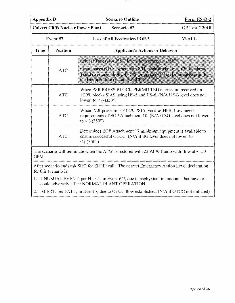
Appendix D Scenario Outline Form ES-D-2
Calvert Cliffs Nuclear Power Plant Scenario #2 OP-Test# 2018
Event #7
Time Position
ATC
ATC
ATC
ATC
Loss of All FeedwaterlEOP-3 M-ALL
Applicant's Actions or Behavior
When PZR PRESS BLOCK PERMITTED alarms are received on I C09, blocks SIAS using HS-5 and HS-6. (NIA if SG level does not lower to < (-)350")
When PZR pressure is <1270 PSIA, verifies HPSI flow meets requirements ofEOP Attachment 10. (NIA if SG level does not lower to< (-)350")
Determines EOP Attachment 17 minimum equipment is available to ensure successful OTCC. (NI A if SG level does not lower to < (-)350")
The scenario will terminate when the AFW is restored with 23 AFW Pump with flow at ~ 150 GPM.
After scenario ends ask SRO for ERPIP call. The correct Emergency Action Level declaration for this scenario is:
1. UNUSUAL EVENT, per HU3. l, in Event 6/7, due to asphyxiant in amounts that have or could adversely affect NORMAL PLANT OPERATION.
2. ALERT, per FAI.I, in Event 7, due to OTCC flow established. (NIA ifOTCC not initiated)
Page 24 of26

SHIFT TURNOVER INFORMATION SHEET 1Bo4591
DATE: Today
MODE OF OPERATION
REACTOR POWER(%)
GENERATION NET (MWe)
Net RCS U.AKAGE (gpm)
RCS BORON (ppm)
ON-COMING SHIFT: DAYS
100
885
0.01
756
100
912
0.0
1609 ----------+-----~----------------------1
UNIT RISK (HIGHEST FOR DAY) CDF: LOW LERF: LOW CDF: LOW LERF: LOW
UNIT RISK COLOR GREEN
BULK POWER NOTIFICATIONS Normal
OD's!RECO's!FA 'sand REF's requested by OPS
Unit Description Date Requested Type
RRS-Y
OCDG
Cond Demin Bypass MOY
GREEN
Resp. ECO
Page 25 of26
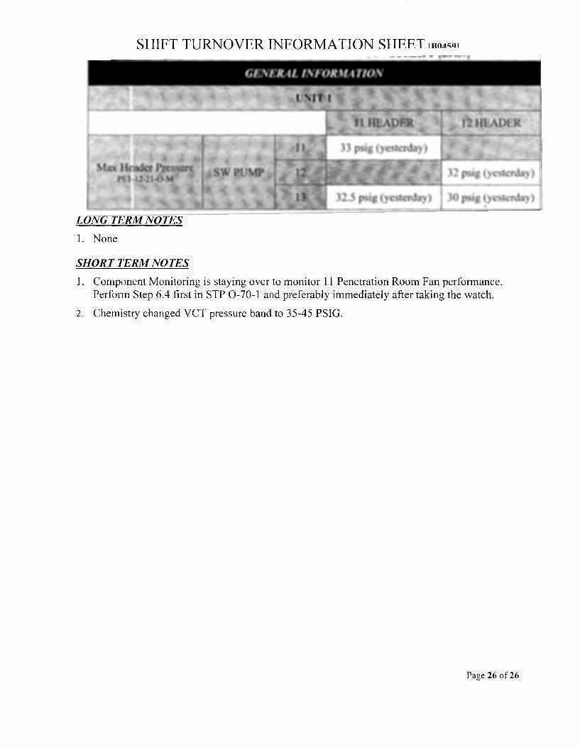
LONG TE"'RM NOTES
1. None
SHORT TERM NOTES
32.5 psig (yesterday) 30 psig (yesterday)
I. Component Monitoring is staying over to monitor 11 Penetration Room Fan performance. Perform Step 6.4 first in STP 0-70-1 and preferably immediately after taking the watch.
2. Chemistry changed VCT pressure band to 35-45 PSIG.
Page 26 of26
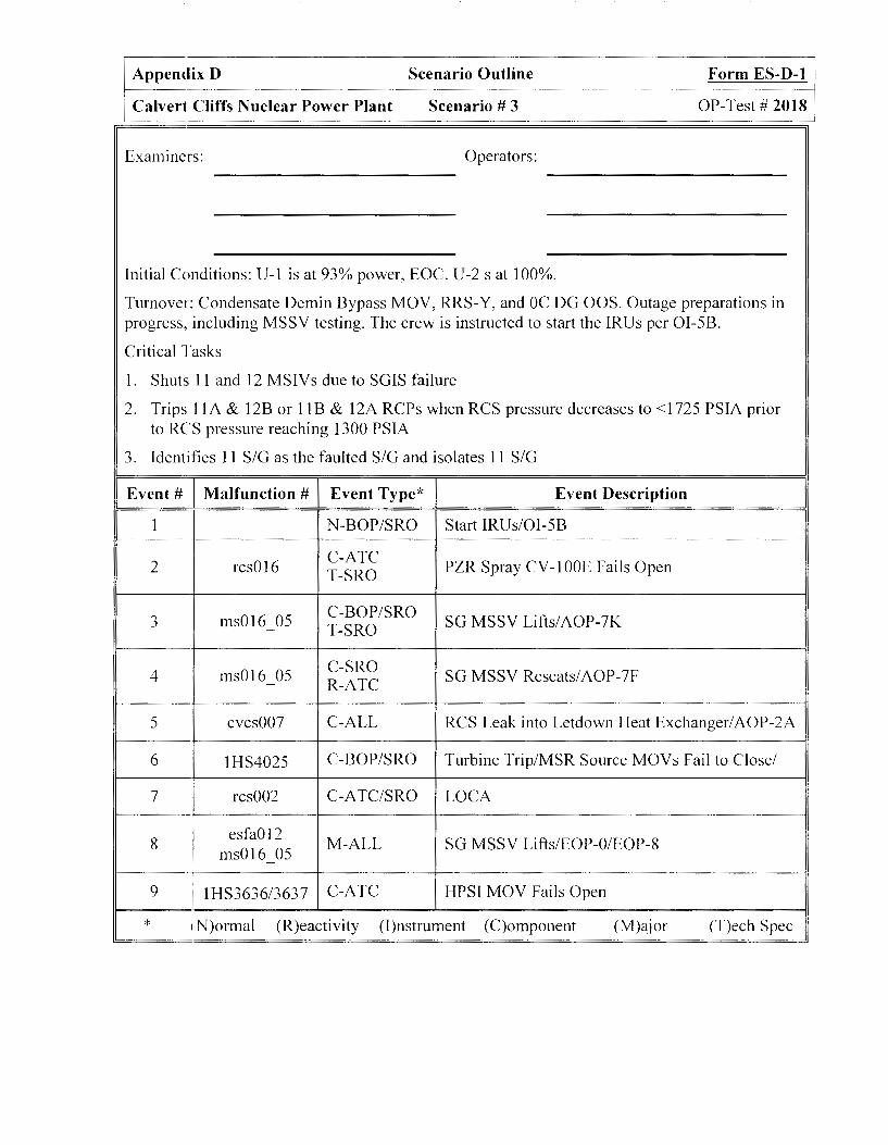
Appendix D Scenario Outline Form ES-D-1
Calvert Cliffs Nuclear Power Plant Scenario# 3 OP-Test# 2018
Examiners: Operators:
Initial Conditions: U-1 is at 93% power, EOC. U-2 s at 100%.
Turnover: Condensate Demin Bypass MOY, RRS-Y, and OC DG OOS. Outage preparations in progress, including MSSY testing. The crew is instructed to start the IRUs per OI-5B.
Critical Tasks
1. Shuts 11 and 12 MSIYs due to SGIS failure
2. Trips 1 lA & l2B or l 1B & 12A RCPs when RCS pressure decreases to <1725 PSIA prior to RCS pressure reaching 1300 PSIA
'") Identifies 11 S/G as the faulted S/G and isolates 11 S/G .) .
Event# Malfunction # Event Type* Event Description
1 N-BOP/SRO Start IRUs/OI-5B
2 rcs016 C-ATC
PZR Spray CY-lOOE Fails Open T-SRO
'") ms016 05 C-BOP/SRO SG MSSY Lifts/AOP-7K .) - T-SRO
4 ms016 05 C-SRO SG MSSY Reseats/ AOP-7F R-ATC
5 cvcs007 C-ALL RCS Leak into Letdown Heat Exchanger/AOP-2A
6 1HS4025 C-BOP/SRO Turbine Trip/MSR Source MOYs Fail to Close/
7 rcs002 C-ATC/SRO LOCA
8 esfa012
M-ALL SG MSSY Lifts/EOP-0/EOP-8 msOl 6 05
9 I 1HS3636/3637 C-ATC HPSI MOY Fails Open
* 1N)ormal (R)eactivity (l)nstrument (C)omponent (M)ajor (T)ech Spec

Appendix D Scenario Outline
Calvert Cliffs Nuclear Power Plant Scenario # 3
Scenario Overview
Initial Conditions: Unit-1 at 93% power, EOC Unit-2 at 100% power Equipment OOS: Condensate Demin Bypass MOY, RRS-Y, and OC DG OOS Abnormal Conditions: MSSV testing in progress Instructions for shift: Start all 3 IRUs for outage preparations
Event 1
Form ES-D-1
OP-Test# 2018
The crew will be requested to start the IRUs to support the Outage schedule. The crew will start all 3 IRUs using OI-5B.
Event 2 PZR Spray CV-IOOE fails open causing pressure to lower below DNB. LCO for Tech Spec 3.4.1 will no longer be met. The crew will respond using the I C06 Alarm Manual. The crew will shift PZR Spray controller output to only CV-I OOF and return RCS pressure to normal.
Event 3 A MSSV on 11 SG will fully lift during testing. The crew will implement AOP-7K and lower Turbine load to restore Tcold to program. Tech Spec 3.7.1 for the inoperable MSSV will be evaluated.
Event 4 The MSSV will reseat abruptly reseat, resulting in a Loss of Load. The crew will implement AOP-7F and lower power to restore Tcold to program.
Event 5 An RCS leak will start in the Letdown Heat Exchanger which will exceed the capacity of a charging pump. The crew will implement AOP-2A and isolate the leak by securing letdown. Charging Pumps will need to be manually cycled after letdown is secured to prevent reaching PZR level TS limit.
Event 6 The Main Turbine will trip due to a Generator fault and EOP-0 will be implemented. The MSR 2nd Stage Source MOVs won't automatically close and the crew will need to manually close the Panel Loader CV s to prevent an uncontrolled cool down.
Event 7 A 300 GPM LOCA into containment will start one minute after the trip. The crew will restart all Charging Pumps due to lowering PZR level. Due to rising Containment pressure and temperature, the crew will start the standby Containment Air Cooler and align Emergency Outlet SR W to all of the Containment Air Coolers.
Page 2 of27
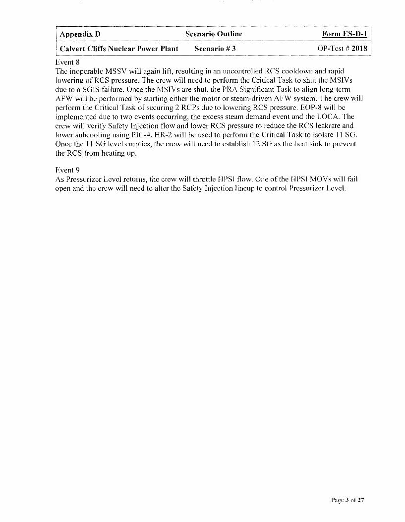
Appendix D Scenario Outline Form ES-D-1
Calvert Cliffs Nuclear Power Plant Scenario# 3 OP-Test# 2018
Event 8 The inoperable MSSV will again lift, resulting in an uncontrolled RCS cooldown and rapid lowering of RCS pressure. The crew will need to perform the Critical Task to shut the MS IVs due to a SGIS failure. Once the MSIVs are shut, the PRA Significant Task to align long-term AFW will be performed by starting either the motor or steam-driven AFW system. The crew will perform the Critical Task of securing 2 RCPs due to lowering RCS pressure. EOP-8 will be implemented due to two events occurring, the excess steam demand event and the LOCA. The crew will verify Safety Injection flow and lower RCS pressure to reduce the RCS leakrate and lower suhcooling using PIC-4. HR-2 will be used to perform the Critical Task to isolate 11 SG. Once the 11 SG level empties, the crew will need to establish 12 SG as the heat sink to prevent the RCS from heating up.
Event 9 As Pressurizer Level returns, the crew will throttle HPSI flow. One of the HPSI MOVs will fail open and the crew will need to alter the Safety Injection lineup to control Pressurizer Level.
Page 3 of27
Appendix D Scenario Outline
Calvert Cliffs Nuclear Power Plant Scenario# 3
Scenario Setup Instructions
I. Reset to IC-36.
2. Place simulator in RUN and advance charts.
3. Place simulator in FREEZE.
4. Enter Triggers:
Form ES-D-1
OP-Test# 2018
a. CEA_ROD _POSITION(l) < 5 (CEA 01 on bottom (I YI O required)) on Event 7
b. CEA_ROD_POSITION(l) < 5 (CEA 01 on bottom (IYIO required)) on Event 8
c. PRES_Jl_P < 1725 (PZR Press goes below 1725 PSIA) on Event 9
5. Enter Malfunctions:
a. esfa012
b. dg002_01
C. rcsO 16 on event 2
d. msO 16 05 on event 3
e. cvcs007 to 45.0 on event 5
f. tgOO I after IO on event 6
g. rcs002 after 60 to 300.0 on event 7
h. msO 16 05 after 3 00 on event 8
6. Enter Remote Functions:
a. 1-MS-4025-MOV to OPEN on event 6
b. l-MS-4026-MOV to OPEN on event 6
C. l-MS-4021 PO to O on event 19
d. l-MS-4024 PO to O on event 19
e. 1-CC-166 to O on event 20
Page 4 of27

Appendix D Scenario Outline Form ES-D-1
Calvert Cliffs Nuclear Power Plant Scenario# 3 OP-Test# 2018
7.
8.
Enter Panel Overrides:
a. Pl C03 1 HS4439 to OPEN
b. PlC03 1MOV4439 LTRED to Off - -
C. PlC03 1HS4439 LTWHIT to Off - -
d. P lC05 D44 LTON to Off - -
e. PlC02 1MOV4025 LTGRE to Off on event 6 - -
f. Pl CO2 1MOV4025 LTRED to On on event 6 - -
g. P1C02 1MOV4026 LTGRE to Off on event 6 - -
h. P1C02 1MOV4026 LTRED to On on event 6 - -
1. Pl COl A54 LTON after 5 to On on event 6
J. Pl C07 X58 LTON to Off on event 9
k. Pl C07 X59 LTON to Off on event 9 - -
1. P 1 COS G03 L TON to Off on event 9 - -
m. PlC09 1HS3636 after 30 to PLTORD on event 9
n. Pl C09 1HS3637 after 30 to PLTORD on event 9
Administrative:
a. Raise Charging and Letdown with 11 and 12 Charging Pumps in service per 0I-2A, Step 6.1.
b. Equalize PZR boron per OP-3.
c. Lower power to 93% using CEAs and boration. Group 5 CEAs should be~ 115" when stable.
d. Adjust Turbine Load to ensure Tcold on program.
e. Place an off normal tag on RRS-Y.
f. Place an "INFO" tag on Condensate Demin Bypass Valve.
g. Place OC DG Output breaker in Pull To Lock.
h. Place "INFO" tags on OC DG Output Breaker, OC Emergency Start. and OC Slow Start pushbuttons.
1. Prepare a sticky to indicate U-1 MAIN STM PIPING RM 315 is in alarm on I C24. Do not initially place the sticky on the panel.
J. Ensure Simulator speaker volume is adjusted correctly.
k. Ensure correct magnetic plaques are in place.
Page 5 of27

Appendix D Scenario Outline Form ES-D-1
Calvert Cliffs Nuclear Power Plant Scenario # 3 OP-Test# 2018
9. Independently verify correct completion of the following:
a. Event Triggers correctly entered
b. Malfunctions correctly entered
c. Remote Functions correctly entered
d. Panel Overrides correctly entered
e. Administrative actions correctly performed
10. Place simulator in RUN.
11. Ensure schedule files are in RUN.
12. Ensure Trigger files are in RUN.
13. Ensure all PPC screens selected to Main Menu, Alarms, or SPDS Operating Summary page.
14. Select "Clock" and ensure "Horn On" for annunciators.
15. Brief the Crew:
I. Present plant conditions: Both Units are at I 00% power
Unit-I is at EOC
2. Power history: Unit-I was lowered to 93% to perform MSSV testing
RRS-Y
3. Equipment out of service: OCDG
Condensate Demin Bypass MOV
4. Abnormal conditions: MSSV testing in progress
5. Surveillances due: None
6. Instructions for shift: Maintain power at 93% for MSSV testing
Start all 3 IRUs for outage preparations
16. Allow crew 3-5 minutes to acclimate themselves with their positions.
Page 6 of27
Appendix D Scenario Outline Form ES-D-1
Calvert Cliffs Nuclear Power Plant Scenario# 3 OP-Test# 2018
17. Instructions for the Booth Operator:
a. Event I: When directed by Lead Examiner, call into Control Room as WEC and state "Outage schedule has us stai1ing the 11-13 IR Us as soon as we take the shift."
b. Event 2: Activate PZR Spray CY-1 OOE Fails Open when directed by the Lead Examiner. Remove malfunction rcsO 16 when the A TC has shifted PRZR SPRAY YL Y SEL HS-100-8 to 1 OOF and only after RCS pressure is< 2200 PSIA. Place a sticky note on the Fire Panel indicating U-1 MAIN STM PIPING RM 315.
c. E,ent 3: Activate SG MSSY Lifts/AOP-7K when directed by the Lead Examiner.
d. E,ent 4: Remove malfunction ms016 05 to activate SG MSSY Reseats/AOP-7F when directed by the Lead Examiner.
e. Event 5: Activate RCS Leak into Letdown Heat Exchanger/AOP-2A when directed by the Lead Examiner.
f. Event 6: Activate Turbine Trip/MSR Source MOYs Fail to Close when directed by the Lead Examiner.
g. Event 7: LOCA is automatically inserted one minute after the trip. No Booth Operator actions are required.
h. Event 8: SG MSSY Lifts/EOP-0/EOP-8 is automatically inserted five minutes after the trip. After MSIY s are closed and 11 SG pressure is < 670 PSIA, remove malfunction esfa012.
1. Event 9: HPSI MOY Fails Open Failure is automatically inserted after RCS pressure lowers below 1725 PSIA. The intent of the malfunction is for only one HPSI Header MOY to fail open. However, the failure is inserted on both Sl-636 and SI-637-MOYs since the Operator plans to throttle HPSI are initially unknown. Once the Operator has determined one of the MOYs is failed open, the override on the opposite MOY should be removed.
1) If 11 HPSI is secured and then SI-636-MOY is discovered failed open, the Booth Operator should remove the override on SI-637-MOY.
2) If 13 HPSI is secured and then SI-637-MOY is discovered failed open, the Booth Operator should remove the override on SI-636-MOY. This will allow the Operator to successfully throttle HPSI.
Page 7 of27
Appendix D Scenario Outline Form ES-D-1
Calvert Cliffs Nuclear Power Plant Scenario# 3 OP-Test# 2018
RESPONSES TO CREW REQUESTS
If a request and response is not listed, delay the response until reviewed with the examiner. If one request is dependent upon completion of another, then subsequent actions should not be responded to until the appropriate time delay has been observed. Responses to routine requests, which have no effect the scenario, do not require examiner clearance.
Allow 2-3 minutes to perform requests from or to give reports to the Control Room unless otherwise specified.
RESPONSE .. . .. ;
REQUEST ;:;,,,; .'.' .. · ; ': "' ;
Event I-Start IRUS/OI-5B
I. WEC informed of issue/status. Acknowledge request. No further actions required.
• Acknowledge request and immediately
2. Painting status in containment. report "There have been no Containment entries yet in support of the pre-outage work."
Event 2- PZR Spray CV-IOOE Fails Open
I. WEC informed of issue/status. Acknowledge request. No further actions required.
Event 3- SG MSSV Lifts/ AOP-7K
I. WEC informed of issue/status. Acknowledge request. No further actions required.
Acknowledge request.
• After 2 minutes, report "The MSSV 2. Status of MSSV testing. being tested on 11 SG has gone full open.
We are determining how to gag the Safety shut."
') Suspend all MSSV testing. Acknowledge request. No further actions
.) . required.
Acknowledge request.
• After 2 minutes, report "There is no fire 4. Unit-] Main Steam Pene Room Fire Alarm. in the MSIV room. It appears that the
MSSV lifting has caused the humidity in the room to rise and activate the alarm."
Page 8 of27
Appendix D Scenario Outline Form ES-D-1
Calvert Cliffs Nuclear Power Plant Scenario# 3 OP-Test# 2018
REQUEST RESPONSE
Event 4- SG MSSV Reseats/AOP-7F
I. WEC informed of issue/status. Acknowledge request. No further actions required.
Acknowledge request and immediately
2. Status of MSSV. report "The 11 SG MSSV went shut on its own. We were not attempting to gag the valve."
Acknowledge request. 3. Any leaking SG safeties on the Aux Building • After 2 minutes, report "There are no
Roof leaking SG Safeties on the Aux Building Roof."
4. Suspend all MSSV testing. Acknowledge request. No further actions required.
Event 5- RCS Leak into Letdown Heat Exchanger/AOP-2A
I. WEC informed of issue/status. Acknowledge request. No further actions required.
2. Rad Con or Chemistry informed of leak. Acknowledge request. No further actions required.
Acknowledge request. 3. Sample SGs per CP-436. • After IO minutes, report "There is no
activity in either SG."
Acknowledge request.
4. Indication of leak in Aux Building. • After 5 minutes, report "There is no indication of an active RCS leak anywhere in the Aux Building."
Acknowledge request. 5. Shut I-CC-166. • After 2 minutes, initiate Director Event
20 and report "l-CC-166 is shut."
Page 9 of27

Appendix D Scenario Outline Form ES-D-1
Calvert Cliffs Nuclear Power Plant Scenario# 3 OP-Test# 2018
REQUEST RESPONSE
Event 6- Turbine Trip/MSR Source MOVs Fail to Close
1. WEC informed of issue/status. Acknowledge request. No further actions required.
Acknowledge request.
2. Verify MSR 2nd Stage Bypass Control Valve • After 2 minutes, initiate Director Event panel loaders in manual with a 0% output. 19 and report "The panel loaders are in
manual with a 0% output."
Event 8-SG MSSV Lifts/EOP-0/EOP-8
1. Status of MSSV. Acknowledge request and immediately report "The 11 SG MSSV went open again."
Acknowledge request.
2. Any leaking SG safeties on the Aux Building • After 2 minutes, report "There is one 11 Roof SG Safety lifting on the Aux Building
Roof."
Acknowledge request.
• After 1 minutes, override desired 1. Ovenide annunciators. annunciator to OFF using OVERRIDEs
and report desired annunciator card has been pulled.
Acknowledge request. 2. Sample SGs per CP-436. • After 10 minutes, report "There is no
activity in either SG."
3. Place H2 monitors in service. Acknowledge request. No further actions required.
Acknowledge request.
4. Align 11 ADV control to l C43, in manual, • After 2 minutes, initiate Director Event
with a 0% output. 18 and report "11 ADV control has been shifted to 1 C43, in manual, with a 0% output."
Acknowledge request.
• After 2 minutes:
• If 11 SG pressure is< 50 PSIA, then 5. Evaluate Safety Valves on Aux Building report "There are no leaking Safety
roof. Valves on the roof."
• IF 11 SG pressure is> 50 PSIA, then report "There is one 11 SG Safety leaking on the Aux Building Roof."
Page 10 of27

Appendix D Scenario Outline Form ES-0-1
Calvert Cliffs Nuclear Power Plant Scenario# 3 OP-Test# 2018
REQUEST RESPONSE
6. Evaluate Safety Valves on Aux Building Acknowledge request.
roof. • After 4 minutes, report there are no leaking Safety Valves on the roof.
Event 9- SG MSSV Lifts/SGIS Failure/EOP-0/EOP-8
Acknowledge request.
• After 2 minutes, report "The breaker for the MOY is closed and is indicating the MOY is open."
1. HPS[ MOV-636/637 local indications. • After 2 more minutes, report "RadCon says it will be another 15 minutes before they will support entry into the Penetration Rooms to evaluate local MOY indications."
Page 11 of27

Appendix D Scenario Outline Form ES-D-2
Calvert Cliffs Nuclear Power Plant Scenario# 3 OP-Test# 2018
Event #1 Start IRUs/01-SB I N-BOP/SRO
Time Position Applicant's Actions or Behavior
SRO Acknowledges WEC request to start IRUs.
SRO Directs BOP to start 11-13 IRUs per 0I-5B.
i BOP Starts 11 IRU using HS-5293 on 1C10 and checks that red light is on above HS.
BOP Starts 12 IRU using HS-5295 on 1C10 and checks that red light is on above HS.
BOP Starts 13 IRU using HS-5297 on 1 C 10 and checks that red light is on above HS.
Examiner notes:
Event concludes when RCS pressure is lowering.
NOTE TO EXAMINER
Cue Booth Operator to initiate Event #2, PZR Spray CV-IOOE Fails Open, when desired.
Page 12 of27

Appendix D Scenario Outline Form ES-D-2
Calvert Cliffs Nuclear Power Plant Scenario# 3 OP-Test# 2018
Event #2 PZR Spray CV-IOOE Fails Open I C-A TC, T-SRO
Time Position Applicant's Actions or Behavior
ATC Notes lowering RCS pressure or PZR CHI 00 PRESS alarm on 1 C06. Informs the SRO.
ATC Refers to 1 C06 Alarm Manual and determines PZR Spray CV, RC-1 OOE-CV, has failed open.
ATC Swaps Pressurizer Spray valve control by placing PRZR SPRAY VL V SEL, HS-100-8, to the 1 OOF position.
ATC Verifies RCS pressure is returning to 2250 PSIA once RC-1 OOE-CV shuts.
SRO Evaluates Tech Spec 3.4.1. Determines LCO 3.4.1 Condition A applied when RCS pressure was < 2200 PSIA.
SRO Notifies the WEC of plant conditions. Requests support.
Examiner notes:
Event concludes when MSSV lifts. If SR O's understanding of the Technical Specification applicability is not clearly observable, follow-up questioning may be required upon completion of the scenario.
NOTE TO EXAMINER
Cue Booth Operator to insert next malfunction, SG MSSV Lifts/ AOP-7K, when desired
Page 13 of27
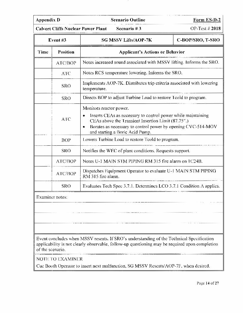
Appendix D Scenario Outline Form ES-D-2
Calvert Cliffs Nuclear Power Plant Scenario# 3 OP-Test# 2018
Event #3 SG MSSV Lifts/AOP-7K C-BOP/SRO, T-SRO
Time Position Applicant's Actions or Behavior
I ATC/BOP Notes increased sound associated with MSSV lifting. Informs the SRO.
I Notes RCS temperature lowering. Informs the SRO. ATC
I
I
Implements AOP-7K. Distributes trip criteria associated with lowering : SRO
temperature. i !
Directs BOP to adjust Turbine Load to restore Tcold to program. / SRO
I Monitors reactor power. I
• Inserts CEAs as necessary to control power while maintaining ATC CEAs above the Transient Insertion Limit (87.75".)
• Borates as necessary to control power by opening CVC-514-MOV and starting a Boric Acid Pump.
BOP Lowers Turbine Load to restore Tcold to program.
SRO Notifies the WEC of plant conditions. Requests support.
ATC/BOP Notes U-1 MAIN STM PIPING RM 315 fire alarm on 1C24B.
ATC/BOP Dispatches Equipment Operator to evaluate U-1 MAIN STM PIPING
I RM 315 fire alarm.
SRO Evaluates Tech Spec 3.7.1. Determines LCO 3.7.1 Condition A applies.
Examiner notes:
Event concludes when MSSV reseats. If SRO's understanding of the Technical Specification applicability is not clearly observable, follow-up questioning may be required upon completion of the scenario.
NOTE TO EXAMINER
Cue Booth Operator to insert next malfunction, SG MSSV Reseats/ AOP-7F, when desired.
Page 14 of27

Appendix D Scenario Outline Form ES-D-2
Calvert Cliffs Nuclear Power Plant Scenario# 3 OP-Test# 2018
Event #4 SG MSSV Reseats/AOP-7F C-SRO, R-A TC
Time Position Applicant's Actions or Behavior
ATC/BOP Notes reduced sound associated with MSSV reseating. Informs the SRO.
ATC Notes RCS temperature rising. Informs the SRO.
SRO Implements AOP-7F.
SRO Directs ATC to lower Reactor Power to restore Tcold to program.
Lowers Reactor Power to restore Tcold to program.
• Inserts CEAs as necessary while maintaining CEAs above the ATC Transient Insertion Limit (87.75".)
• Borates as necessary by opening CVC-514-MOV and starting a Boric Acid Pump.
BOP May adjust TURBINE BYPASS VL V CONTR, PIC-4056, setpoint just above Main Steam header pressure but not lower than 830 PSIA.
SRO Notifies the WEC of plant conditions. Requests support.
Examiner notes:
Event concludes when LID PRESS alarms on 1 C07.
NOTE TO EXAMINER
Cue Booth Operator to insert next malfunction, RCS Leak into Letdown Heat Exchanger/ AOP-2A. when desired.
Page 15 of27

Appendix D Scenario Outline Form ES-D-2
Calvert Cliffs Nuclear Power Plant Scenario# 3 OP-Test# 2018
Event #5 RCS Leak into Letdown Heat
C-ALL Exchanger/AOP-2A
Time Position Applicant's Actions or Behavior
ATC Notes LID PRESS alarms on 1 C07. Determines letdown pressure is
! low. Informs the SRO. : I
BOP Notes RAD MON PANEL 1C22 alarm on lCl 7. Determines Unit-I CC is in alarm on 1 C22. Informs the SRO.
BOP Bypasses Unit-I CC RMS on 1C22 to restore RAD MON PANEL 1 C22 alarm on 1 C 1 7.
BOP/SRO Evaluates Component Cooling RMS, RIC-3819. Determines RMS level is rising.
BOP/SRO Evaluates Component Cooling Head Tank level. Determines level is .. nsmg.
ATC Determines PZR level is lowering. Informs the SRO.
SRO Implements AOP-2A. Distributes trip criteria on TM/LP status.
ATC/SRO Determines leak is exceeding the capacity of a Charging Pump.
SRO Implements AOP-2A section for RCS leakage exceeding one Charging Pump.
ATC/BOP Isolates letdown by shutting CVC-515-CV and CVC-516-CV.
Event #5 continues on next page
Examiner notes:
Page 16 of27

Appendix D Scenario Outline Form ES-D-2
Calvert Cliffs Nuclear Power Plant Scenario# 3 OP-Test# 2018
Event #5 RCS Leak into Letdown Heat
C-ALL Exchanger/ AOP-2A
Time Position Applicant's Actions or Behavior
ATC Controls PZR level < 225" by securing 11 and 12 Charging Pumps.
ATC/BOP Determines the leak is not on the Charging Header.
BOP Determines leak is not occurring inside Containment.
BOP Starts 11 Penetration Room Ventilation Fan using HS-5283 and 12 Penetration Room Ventilation Fan using HS-5284.
BOP/SRO Determines RCS leak is into the Component Cooling Water system.
Evaluates Component Cooling system indications with letdown
BOP/SRO isolated:
• Determines Head Tank level is steady/no longer rising
• Determines RMS indications are no longer rising
ATC/BOP Shifts CVC-500-CV to WPS.
ATC/BOP Shifts TIC-223 to manual with a 100% output signal.
BOP Directs Equipment Operator to shut l-CC-166.
Examiner notes:
Event concludes when UNIT XFMR HI SIDE LEADS DIFF alarms on 1 COI.
NOTE TO EXAMINER
Cue Booth Operator to insert next malfunction, Turbine Trip/MSR Source MOVs Fail to Close/SG MSSV Lifts/SGIS Failure/EOP-0, when desired.
Page 17 of27

Appendix D Scenario Outline Form ES-D-2
Calvert Cliffs Nuclear Power Plant Scenario# 3 OP-Test# 2018
Event #6 Turbine Trip/MSR Source MOVs Fail to
C-BOP/SRO Close
Time Position Applicant's Actions or Behavior
ATC Determines that Reactor has tripped.
SRO Implements EOP-0.
ATC Determines Reactivity Safety Function is met. Informs the SRO that Reactivity is complete.
BOP Determines both MSR 2nd Stage Steam Source MOVs are not shut.
BOP Places MSR 2nd Stage High Load MOVs HS-4018 in CLOSE.
BOP Directs an Equipment Operator to verify MSR 2nd Stage Bypass Control Valve panel loaders in manual with a 0% output.
BOP Determines Turbine Trip Safety Function is met. Informs the SRO that Turbine Trip is complete.
Examiner notes:
Event concludes after Turbine Trip is reported to the Unit Supervisor.
NOTE TO EXAMINER
Event #7, LOCA, is automatically inserted one minute after the trip. The Booth Operator is not required to initiate the malfunction.
Page 18 of27

Appendix D Scenario Outline Form ES-D-2
Calvert Cliffs Nuclear Power Plant Scenario# 3 OP-Test# 2018
Event #7 LOCA C-ATC
Time Position Applicant's Actions or Behavior
ATC Starts all Charging Pumps due to lowering PZR level.
Determines Pressure and Inventory Safety Function is not met. ATC Informs the SRO that Pressure and Inventory Safety Function is not
met due to low pressure and low level.
BOP Determines Vital Auxiliaries Safety Function is met. Informs the SRO that Vital Auxiliaries is complete.
BOP If adjusted, returns TURBINE BYPASS VL V CONTR, PIC-4056, setpoint to 900 PSIA.
ATC/BOP Notes Containment Normal Sump level high alarm on ICIO. Informs the SRO.
ATC/BOP Starts 13 Containment Air Cooler in High Speed.
ATC/BOP Opens Emergency Outlet SRW Valves on all Containment Air Coolers.
Determines Containment Environment Safety Function is not met. ATC/BOP Informs the SRO that Containment Environment is not met due to
high pressure and temperature.
Examiner notes:
Event concludes when MSSV lifts.
NOTE TO EXAMINER
Event #8, SG MSSV Lifts/EOP-O/EOP-8, is automatically inserted five minutes after the trip. The Booth Operator is not required to initiate the malfunction. The Booth Operator will need to remove the SGIS malfunction after the MSIVs are shut.
Page 19 of27

Appendix D Scenario Outline Form ES-D-2
Calvert Cliffs Nuclear Power Plant Scenario # 3 OP-Test# 2018
Event #8
Time Position
ATC/BOP
BOP
BOP
ATC
ATC
ATC
BOP
Examiner notes:
SG MSSV Lifts/EOP-0/EOP-8 M-ALL
Applicant's Actions or Behavior
Notes increased sound associated with MSSV lifting. Informs the SRO.
Determines SG pressure is< 800 PSIA and shuts both 11 and 12 MSIVs.
Verifies SIAS by checking:
• ACTUATION SYS SIAS TRIP alarm is received on 1 C08 • 11 and 13 HPSI pumps are running • All HPSI header MOVs are open Informs the SRO that SIAS is verified.
Determines RCS pressure is < 1725 PSIA and secures either 11 A and 12B RCPs OR l lB and 12A RCPs.
Determines Main Feedwater will be lost due to shutting the MSIVs. Initiates Auxiliary Feedwater by starting either 11 or 13 AFW Pump.
Event #8 continued on next page.
Page 20 of27

Appendix D Scenario Outline Form ES-D-2
Calvert Cliffs Nuclear Power Plant Scenario# 3 OP-Test# 2018
Event #8 SG MSSV Lifts/EOP-0/EOP-8 M-ALL
Time Position Applicant's Actions or Behavior
Determines Core and RCS Heat Removal Safety Function is not met. BOP Informs the SRO that Core and RCS Heat Removal is not met due to
low Tcold and low SG pressures.
Determines the Radiation Levels External to Containment Safety ATC/BOP Function is met. Informs the SRO that Radiation Levels External to
Containment is complete.
Verifies SGIS by checking:
BOP • ACTUATION SYS SGIS A TRIP alarm is received on I C08
• Verifies FW MOV-45I6 and MOV-45I 7 are shut Informs the SRO that SGIS is verified
SRO Evaluates the EOP-0 flowchart and recommends the implementation ofEOP-8.
SRO Directs implementation of EOP-8.
SRO Directs Chemistry to perform samples on both S/Gs and place the Hydrogen Monitors in service.
Evaluates Resource Assessment Table. Determines that RC-I is met, ATC/BOP VA-I is met, PIC-4 is met, HR-2 is met, CE-I is met, and RLEC-I is
met. Informs the SRO of assessment results.
Event #8 continued on next page.
Examiner notes:
Page 21 of27

Appendix D Scenario Outline Form ES-D-2
Calvert Cliffs Nuclear Power Plant Scenario# 3 OP-Test# 2018
Event #8 SG MSSV Lifts/EOP-0/EOP-8 M-ALL
Time Position Applicant's Actions or Behavior
Evaluates Resource Assessment Table. Determines that RC- I is met,
SRO VA-I is met, PIC-4 is met, HR-2 is met, CE-I is met, and RLEC-1 is met. Prioritizes Success Paths and determines PIC-4 and HR-2 should be implemented first.
SRO Directs the A TC to implement PIC-4.
SRO Directs the BOP to implement HR-2.
ATC Verifies HPSI flow meets the requirements ofEOP Attachment 10.
ATC Lowers subcooling by cycling Aux Spray CVC-517 and cycling Loop Stops CVC-518 and CVC-519.
Verifies AF AS Block by checking:
• 11 STM LINE RUPTURE alarm is received on I C03 BOP • Verifies 11 S/G AFW BLOCK valves, AFW-4520-CV, AFW-
4521-CV, AFW-4522-CV, AFW-4523-CV are shut. Informs the SRO that AF AS Block is verified
Event #8 continued on next page.
Examiner notes:
Page 22 of27

Appendix D Scenario Outline Form ES-D-2
Calvert Cliffs Nuclear Power Plant Scenario# 3 OP-Test# 2018
Event #8 SG MSSV Lifts/EOP-0/EOP-8 M-ALL
Time Position Applicant's Actions or Behavior
Verifies AF AS by checking:
• AF AS ACTUATED alarms are received on 1 C04 BOP/SRO • Verifies MS-4070-CV and MS-4071-CV are opening
BOP/SRO
BOP
Examiner notes:
• Verifies 13 AFW is running Informs the SRO that AF AS is verified
Identifies 11 SG as the most affected SG.
Event #8 continued on next page.
Page 23 of27

Appendix D Scenario Outline Form ES-D-2
Calvert Cliffs Nuclear Power Plant Scenario# 3 OP-Test# 2018
Event #8 SG MSSV Lifts/EOP-0/EOP-8 M-ALL
Time Position Applicant's Actions or Behavior
Secures the Main Feedwater System:
• Places 11-13 Condensate Booster Pumps in PULL TO LOCK BOP Places two Condensate Pumps in PULL TO LOCK •
• Places 11 and 12 Heater Drain Pumps in PULL TO LOCK
• Shifts LIC-4405 to manual with a 50% output
BOP/SRO Determines that 11 SG blowdown is complete and RCS is beginning to heat up.
BOP Opens 12 ADV to maintain RCS temperature.
Examiner notes:
Event concludes after PZR level is> IOI".
NOTE TO EXAMINER
Event #9, HPSI Header MOV Failure, is automatically inserted when the RCS pressure goes below 1725 PSIA. The Booth Operator is not required to initiate the HPSI Header MOV Failure. The Booth Operator will need to remove the malfunction on the HPSI header chosen to throttle HPSI flow.
Page 24 of27

Appendix D Scenario Outline Form ES-D-2
Calvert Cliffs Nuclear Power Plant Scenario # 3 OP-Test# 2018
Event #9 HPSI MOV Fails Open I C-ATC
Time Position Applicant's Actions or Behavior
ATC Determines PZR level is > 101" and HPSI flow can be throttled.
Verifies HPSI Throttling criteria are met by:
ATC • Verifying SCM is >25°F
• PZR level is >101"
• 11 SIG is available for heat removal
Lowers HPSI flow by: ATC
Securing either 11 or 13 HPSI pump • • Throttling shut on the running pumps HPSI header MOVs .
ATC Notes that SI-636-MOV or SI-637-MOV fails to throttle shut. Informs the SRO.
Lowers HPSI flow by either:
• Securing the running HPSI pump
ATC OR
• Starting the secured HPSI pump
• Securing the HPSI pump with the open header MOY
• Throttling shut on the running pumps HPSI header MOVs
ATC Maintains PZR level 101-180".
Examiner notes:
The scenario will terminate when the Critical Tasks for Shutting the MSIVs, Securing 2 RCPs and Isolating 11 SG have been completed.
After scenario ends ask SRO for ERPIP call. The correct Emergency Action Level declaration for this scenario is:
1. ALERT, per FAl. Lin Event 7, due to RCS leakrate exceeding 50 GPM with LID isolated.
Page 25 of27

SHIFT TURNOVER INFORMATION SHEET 1so4591
DATE: Today
MODE OF OPERATION
REACTOR POWER(%)
GENERATION NET (MWe)
Net RCS LEAKAGE (gpm)
RCS BORON (ppm)
93
821
0.01
205
100
912
0.0
1609 --------t------------,-----+------.---------,
UNIT RISK (HIGHEST FOR DAY) CDF: LOW LERF: LOW CDF: LOW LERF: LOW
UNIT RISK COLOR GREEN
BULK POWER NOTIFICATIONS Normal
OD's/RECO's/FA 'sand REF's requested by OPS
Unit Description Date Requested Type
RRS-Y
OCDG
Cond Demin Bypass MOY
GREEN
Resp. ECD
UNIT2
Page 26 of27

LONG TERM NOTES
1. None
SHORT TERM NOTES
30 psig (yesterday)
1. Need to start 11, 12, and 13 IRUs after taking the watch per the Outage schedule.
Page 27 of27