Appendix A_Sizing and Capacities of Gas Piping
4
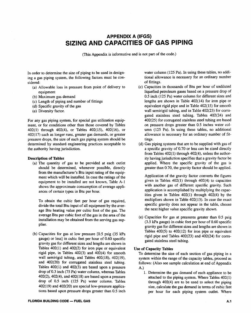
APPENDIX A (IFGS) SIZING AND CAPACITIES OF GAS PIPING (This Appendix is informative and is not part of the code.) In order to determine the size of piping to be used in design- ing a gas piping system, the following factors must be con- sidered: (a) Allowable loss in pressure from point of delivery to equipment (b) Maximum gas demand (c) Length of piping and number of fittings (d) Specific gravity of the gas (e) Diversity factor. For any gas piping system, for special gas utilization equip- ment, or for conditions other than those covered by Tables 402(1) through 402(4), or Tables 402(15), 402(16), or 402(17) such as longer runs, greater gas demands, or greater pressure drops, the size of each gas piping system should be determined by standard engineering practices acceptable to the authority having jurisdiction. Description of Tables (a) The quantity of gas to be provided at each outlet should be determined, whenever possible, directly from the manufacturer's Btu input rating of the equip- ment which will be installed. In case the ratings of the equipment to be installed are not known, Table A-l shows the approximate consumption of average appli- ances of certain types in Btu per hour. To obtain the cubic feet per hour of gas required, divide the total Btu input of all equipment by the aver- age Btu heating value per cubic foot of the gas. The average Btu per cubic foot of the gas in the area of the installation may be obtained from the serving gas sup- plier. (b) Capacities for gas at low pressure [0.5 psig (35 kPa gauge) or less] in cubic feet per hour of 0.60 specific gravity gas for different sizes and lengths are shown in Tables 402(1) and 402(2) for iron pipe or equivalent rigid pipe, in Tables 402(3) and 402(4) for smooth wall semirigid tubing, and Tables 402(18), 402(19), and 402(20) for corrugated stainless steel tubing. Tables 402(1) and 402(3) are based upon a pressure drop of 0.3 inch (75 Pa) water column, whereas Tables 402(2), 402(4), and 402(18) are based upon a pressure drop of 0.5 inch (125 Pa) water column. Tables 402(19) and 402(20) are special low-pressure applica- tions based upon pressure drops greater than 0.5 inch water column (125 Pa). In using these tables, no addi- tional allowance is necessary for an ordinary number of fittings. (c) Capacities in thousands of Btu per hour of undiluted liquefied petroleum gases based on a pressure drop of 0.5 inch (125 Pa) water column for different sizes and lengths are shown in Table 402(14) for iron pipe or equivalent rigid pipe and in Table 402(15) for smooth wall semirigid tubing, and in Table 402(23) for corru- gated stainless steel tubing. Tables 402(24) and 402(25) for corrugated stainless steel tubing are based on pressure drops greater than 0.5 inches water col- umn (125 Pa). In using these tables, no additional allowance is necessary for an ordinary number of fit- tings. (d) Gas piping systems that are to be supplied with gas of a specific gravity of 0.70 or less can be sized directly from Tables 402(1) through 402(4), unless the author- ity having jurisdiction specifies that a gravity factor be applied. Where the specific gravity of the gas is greater than 0.70, the gravity factor should be applied. Application of the gravity factor converts the figures given in Tables 402(1) through 402(4) to capacities with another gas of different specific gravity. Such application is accomplished by multiplying the capac- ities given in Tables 402(1) through 402(4) by the multipliers shown in Table 402(13). In case the exact specific gravity does not appear in the table, choose the next higher value specific gravity shown. (e) Capacities for gas at pressures greater than 0.5 psig (3.5 kPa gauge) in cubic feet per hour of 0.60 specific gravity gas for different sizes and lengths are shown in Tables 402(5) to 402(12) for iron pipe or equivalent rigid pipe and Tables 402(23) and 402(24) for corru- gated stainless steel tubing. Use of Capacity Tables To determine the size of each section of gas piping in a system within the range of the capacity tables, proceed as follows: (Also see sample calculation at end of Appendix A.) 1. Determine the gas demand of each appliance to be attached to the piping system. Where Tables 402(1) through 402(4) are to be used to select the piping size, calculate the gas demand in terms of cubic feet per hour for each piping system outlet. Where FLORIDA BUILDING CODE — FUEL GAS A.1
-
Upload
tohid-karimi -
Category
Documents
-
view
13 -
download
1
description
Sizing and Capacities of Gas Piping
Transcript of Appendix A_Sizing and Capacities of Gas Piping
APPENDIX A (IFGS)SIZING AND CAPACITIES OF GAS PIPING
(This Appendix is informative and is not part of the code.)
In order to determine the size of piping to be used in design-ing a gas piping system, the following factors must be con-sidered:
(a) Allowable loss in pressure from point of delivery toequipment
(b) Maximum gas demand(c) Length of piping and number of fittings(d) Specific gravity of the gas(e) Diversity factor.
For any gas piping system, for special gas utilization equip-ment, or for conditions other than those covered by Tables402(1) through 402(4), or Tables 402(15), 402(16), or402(17) such as longer runs, greater gas demands, or greaterpressure drops, the size of each gas piping system should bedetermined by standard engineering practices acceptable tothe authority having jurisdiction.
Description of Tables(a) The quantity of gas to be provided at each outlet
should be determined, whenever possible, directlyfrom the manufacturer's Btu input rating of the equip-ment which will be installed. In case the ratings of theequipment to be installed are not known, Table A-lshows the approximate consumption of average appli-ances of certain types in Btu per hour.
To obtain the cubic feet per hour of gas required,divide the total Btu input of all equipment by the aver-age Btu heating value per cubic foot of the gas. Theaverage Btu per cubic foot of the gas in the area of theinstallation may be obtained from the serving gas sup-plier.
(b) Capacities for gas at low pressure [0.5 psig (35 kPagauge) or less] in cubic feet per hour of 0.60 specificgravity gas for different sizes and lengths are shown inTables 402(1) and 402(2) for iron pipe or equivalentrigid pipe, in Tables 402(3) and 402(4) for smoothwall semirigid tubing, and Tables 402(18), 402(19),and 402(20) for corrugated stainless steel tubing.Tables 402(1) and 402(3) are based upon a pressuredrop of 0.3 inch (75 Pa) water column, whereas Tables402(2), 402(4), and 402(18) are based upon a pressuredrop of 0.5 inch (125 Pa) water column. Tables402(19) and 402(20) are special low-pressure applica-tions based upon pressure drops greater than 0.5 inch
water column (125 Pa). In using these tables, no addi-tional allowance is necessary for an ordinary numberof fittings.
(c) Capacities in thousands of Btu per hour of undilutedliquefied petroleum gases based on a pressure drop of0.5 inch (125 Pa) water column for different sizes andlengths are shown in Table 402(14) for iron pipe orequivalent rigid pipe and in Table 402(15) for smoothwall semirigid tubing, and in Table 402(23) for corru-gated stainless steel tubing. Tables 402(24) and402(25) for corrugated stainless steel tubing are basedon pressure drops greater than 0.5 inches water col-umn (125 Pa). In using these tables, no additionalallowance is necessary for an ordinary number of fit-tings.
(d) Gas piping systems that are to be supplied with gas ofa specific gravity of 0.70 or less can be sized directlyfrom Tables 402(1) through 402(4), unless the author-ity having jurisdiction specifies that a gravity factor beapplied. Where the specific gravity of the gas isgreater than 0.70, the gravity factor should be applied.
Application of the gravity factor converts the figuresgiven in Tables 402(1) through 402(4) to capacitieswith another gas of different specific gravity. Suchapplication is accomplished by multiplying the capac-ities given in Tables 402(1) through 402(4) by themultipliers shown in Table 402(13). In case the exactspecific gravity does not appear in the table, choosethe next higher value specific gravity shown.
(e) Capacities for gas at pressures greater than 0.5 psig(3.5 kPa gauge) in cubic feet per hour of 0.60 specificgravity gas for different sizes and lengths are shown inTables 402(5) to 402(12) for iron pipe or equivalentrigid pipe and Tables 402(23) and 402(24) for corru-gated stainless steel tubing.
Use of Capacity TablesTo determine the size of each section of gas piping in asystem within the range of the capacity tables, proceed asfollows: (Also see sample calculation at end of AppendixA.)
1. Determine the gas demand of each appliance to beattached to the piping system. Where Tables 402(1)through 402(4) are to be used to select the pipingsize, calculate the gas demand in terms of cubic feetper hour for each piping system outlet. Where
FLORIDA BUILDING CODE — FUEL GAS A.1
APPENDIX A
Tables 402(14) through 402(16) are to be used toselect the piping size, calculate the gas demand interms of thousands of Btu per hour for each pipingsystem outlet.
2. Where the piping system is for use with other thanundiluted liquefied petroleum gases, determine thedesign system pressure, the allowable loss in pres-sure (pressure drop), and the specific gravity of thegas to be used in the piping system.
3. Measure the length of piping from the point ofdelivery to the most remote outlet in the building.
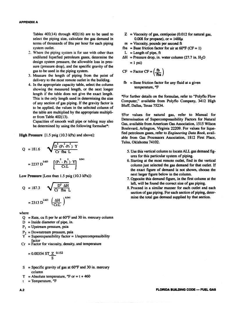
4. In the appropriate capacity table, select the columnshowing the measured length, or the next longerlength if the table does not give the exact length.This is the only length used in determining the sizeof any section of gas piping. If the gravity factor isto be applied, the values in the selected column ofthe table are multiplied by the appropriate multipli-er from Table 402(13).Capacities of smooth wall pipe or tubing may alsobe determined by using the following formulae*:
High Pressure [1.5 psig (10.3 kPa) and above]:
Low Pressure [Less than l.5 psig (10.3 kPa)]:
whereQ = Rate, cu ft per hr at 60°F and 30 in. mercury columnD = Inside diameter of pipe, in.P1 = Upstream pressure, psiaP2 = Downstream pressure, psiaY = Superexpansibility factor = 1/supercompressibility
factorCr = Factor for viscosity, density, and temperature
S = Specific gravity of gas at 60°F and 30 in. mercurycolumn
T = Absolute temperature, °F or = t + 460t = Temperature, °F
A.2
Z = Viscosity of gas, centipoise (0.012 for natural gas,0.008 for propane), or = 1488
m = Viscosity, pounds per second ftfba = Base friction factor for air at 60°F (CF = 1)
L = Length of pipe, ftH = Pressure drop, in. water column (27.7 in. H2O
= 1 psi)
fb = Base friction factor for any fluid at a giventemperature, °F
*For further details on the formulae, refer to "Polyflo RowComputer," available from Polyflo Company, 3412 HighBluff, Dallas, Texas 75234.
For values for natural gas, refer to Manual forDetermination of Supercompressibility Factors for NaturalGas, available from American Gas Association, 1515 WilsonBoulevard, Arlington, Virginia 22209. For values for lique-fied petroleum gases, refer to Engineering Data Book, avail-able from Gas Processors Association, 1812 First Place,Tulsa, Oklahoma 74102.
5. Use this vertical column to locate ALL gas demand fig-ures for this particular system of piping.
6. Starting at the most remote outlet, find in the verticalcolumn just selected the gas demand for that outlet. Ifthe exact figure of demand is not shown, choose thenext larger figure below in the column.
7. Opposite this demand figure, in the first column at theleft, will be found the correct size of gas piping.
8. Proceed in a similar manner for each outlet and eachsection of gas piping. For each section of piping, deter-mine the total gas demand supplied by that section.
FLORIDA BUILDING CODE — FUEL GAS
APPENDIX A
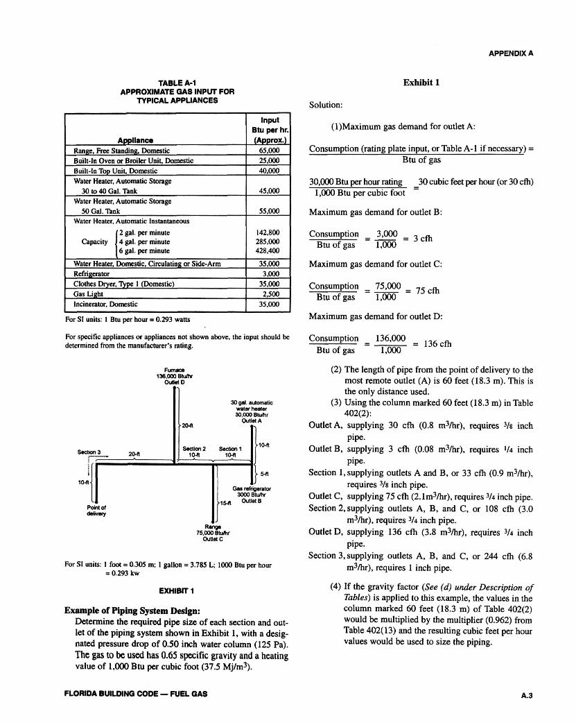
Exhibit 1TABLE A-1APPROXIMATE GAS INPUT FOR
TYPICAL APPLIANCES
ApplianceRange, Free Standing, DomesticBuilt-in Oven or Broiler Unit, DomesticBuilt-In Top Unit, DomesticWater Heater, Automatic Storage
30 to 40 Gal. TankWater Heater, Automatic Storage
SO Gal. TankWater Heater, Automatic Instantaneous
Water Heater, Domestic, Circulating or Side-ArmRefrigeratorClothes Dryer, Type 1 (Domestic)Gas LightIncinerator, Domestic
InputBtu per hr.(Approx.)
65,00025,00040,000
45,000
55,000
142,800285,000428,400
35,0003,000
35,0002,500
35,000
For SI units: I Btu per hour = 0.293 watts
For specific appliances or appliances not shown above, the input should bedetermined from the manufacturer's rating.
For SI units. 1 foot = 0.305 m; 1 gallon = 3.785 L; 1000 Btu per hour= 0.293 kw
EXHIBIT 1
Example of Piping System Design:Determine the required pipe size of each section and out-let of the piping system shown in Exhibit 1, with a desig-nated pressure drop of 0.50 inch water column (125 Pa).The gas to be used has 0.65 specific gravity and a heatingvalue of 1,000 Btu per cubic foot (37.5 Mj/m3).
FLORIDA BUILDING CODE — FUEL GAS
Solution:
(2) The length of pipe from the point of delivery to themost remote outlet (A) is 60 feet (18.3 m). This isthe only distance used.
(3) Using the column marked 60 feet (18.3 m) in Table402(2):
Outlet A, supplying 30 cfh (0.8 m3/hr), requires 3/8 inchpipe.
Outlet B, supplying 3 cfh (0.08 m3/hr), requires 1/4 inchpipe.
Section 1, supplying outlets A and B, or 33 cfh (0.9 m3/hr),requires 3/8 inch pipe.
Outlet C, supplying 75 cfh (2.1m3/hr), requires 3/4 inch pipe.Section 2, supplying outlets A, B, and C, or 108 cfh (3.0
m3/hr), requires 3/4 inch pipe.Outlet D, supplying 136 cfh (3.8 m3/hr), requires 3/4 inch
pipe.Section 3, supplying outlets A, B, and C, or 244 cfh (6.8
m3/hr), requires 1 inch pipe.
(4) If the gravity factor (See (d) under Description ofTables) is applied to this example, the values in thecolumn marked 60 feet (18.3 m) of Table 402(2)would be multiplied by the multiplier (0.962) fromTable 402(13) and the resulting cubic feet per hourvalues would be used to size the piping.
A.3

A.4 FLORIDA BUILDING CODE — FUEL GAS