Appendix A. Flow Analysis Documents - CERNcern.ch/proj-hiptarget/doc/MERIT Design Ops Report...
199
A-1 Appendix A. Flow Analysis Documents
Transcript of Appendix A. Flow Analysis Documents - CERNcern.ch/proj-hiptarget/doc/MERIT Design Ops Report...

A-1
Appendix A. Flow Analysis Documents

MERIT SYRINGE FLOW ANALYSISC:\Documents and Settings\vbg.ORNL\My Documents\My Files\MERIT\Hg System\Fathom\MERIT Design R1.fthBase Scenario
P9>L=130 cmDh=0.884 inchesA=3.96 cm2Hg Supply Straight
P7>L=4.42 cmDh=0.884 inchesA=3.96 cm2Hg Supply Piping
P4^L=14.2 cmDh=1.05 inchesA=5.58 cm2Cylinder Discharge Pipe
P2>L=3.17 cmDh=1.05 inchesA=5.58 cm2Cylinder Discharge Pipe
P1>L=38.1 cmDh=10.0 inchesA=509 cm2Hg Cylinder
<P10L=9.14 cmDh=0.884 inchesA=3.96 cm2Reducer Inlet
P5>L=3.05 cmDh=1.05 inchesA=5.58 cm2Hose Inlet
P8>L=4.39 cmDh=0.884 inchesA=3.96 cm2Hg Supply Piping
P3^L=11.6 cmDh=1.05 inchesA=5.58 cm2Cylinder Discharge Pipe
P6>L=34.3 cmDh=1.10 inchesA=6.10 cm2Flex Hose
<P11L=3.81 cmDh=0.370 inchesA=0.694 cm2Nozzle tubing
J5El_in=30.1 cm
J12El_in=28.4 cm
J2El_in=0.00 cm
J1 vEl_in=0.00 cm
J3El_in=0.00 cm
J11El_in=28.4 cm
J7El_in=33.9 cm
J6El_in=33.9 cm
J8El_in=33.9 cm
J4El_in=13.3 cm
J9El_in=33.9 cm
J10El_in=33.9 cm

AFT Fathom 5.0 Output 4/25/2006SNS
MERIT SYRINGE FLOW ANALYSIS Hg Syringe ModelReference 25 Apr 2006
(1 of 5)

AFT Fathom 5.0 Output 4/25/2006SNS
MERIT SYRINGE FLOW ANALYSIS Execution Time= 0.08 secondsTotal Number Of Head/Pressure Iterations= 0Total Number Of Flow Iterations= 2Total Number Of Temperature Iterations= 2Number Of Pipes= 11Number Of Junctions= 12Matrix Method= Gaussian Elimination Pressure/Head Tolerance= 0.0001 relative changeFlow Rate Tolerance= 0.0001 relative changeTemperature Tolerance= 0.0001 relative changeFlow Relaxation= (Automatic)Pressure Relaxation= (Automatic) Heat Transfer with Energy BalanceFluid Database: AFT StandardFluid: MercuryMax Fluid Temperature Data= 500 deg. FMin Fluid Temperature Data= 0 deg. FDefault Temperature= 80 deg. FDefault Density= 846.7027 lbm/ft3Default Viscosity= 3.69638 lbm/hr-ftDefault Vapor Pressure= 1.0636E-04 atmViscosity Model= Newtonian Atmospheric Pressure= 1 atmGravitational Acceleration= 1 gTurbulent Flow Above Reynolds Number= 4000Laminar Flow Below Reynolds Number= 2300
(2 of 5)

AFT Fathom 5.0 Output 4/25/2006SNS
MERIT SYRINGE FLOW ANALYSIS ***WARNING*** HGL, EGL and head loss results may not be meaningful for variable density systems.
(3 of 5)

AFT Fathom 5.0 Output 4/25/2006SNS
MERIT SYRINGE FLOW ANALYSIS
Pipe Output TablePipe Name
1 Hg Cylinder
PipeNominal
Size10 inch
Vol.Flow
(liter/sec)1.57
Length
(cm)38.10
FlowArea(cm2)508.736
Velocity
(cm/sec)3.09
ReynoldsNo.
6.86E+04
fL/D + K
0.0296
P Stag.In
(barG)42.6
P Stag.Out
(barG)42.6
dP Stag.Total(bar)
0.00000191
P StaticIn
(barG)42.63
P StaticOut
(barG)4.26E+01
dP StaticTotal(bar)
0.000001912 Cylinder Discharge Pipe 1 inch 1.57 3.17 5.576 281.63 6.56E+05 0.0213 42.4 42.4 0.01147854 41.83 4.18E+01 0.011478543 Cylinder Discharge Pipe 1 inch 1.57 11.58 5.576 281.63 6.56E+05 0.0778 42.1 42.0 0.19407322 41.61 4.14E+01 0.194073224 Cylinder Discharge Pipe 1 inch 1.57 14.22 5.576 281.63 6.56E+05 0.0955 41.8 41.5 0.23406301 41.23 4.10E+01 0.234063015 Hose Inlet 1 inch 1.57 3.05 5.576 281.63 6.56E+05 0.0205 41.3 41.3 0.01101942 40.76 4.07E+01 0.011019426 Flex Hose 1 inch 1.57 34.29 6.098 257.53 6.27E+05 0.2186 41.3 41.2 0.09844139 40.83 4.07E+01 0.098441397 Hg Supply Piping 3/4 inch 1.57 4.42 3.960 396.58 7.78E+05 0.0362 40.9 40.9 0.03869272 39.87 3.98E+01 0.038692728 Hg Supply Piping 3/4 inch 1.57 4.39 3.960 396.58 7.78E+05 0.0360 40.7 40.7 0.03847035 39.66 3.96E+01 0.038470359 Hg Supply Straight 3/4 inch 1.57 130.30 3.960 396.58 7.78E+05 1.0684 40.5 39.4 1.14076805 39.44 3.83E+01 1.14076805
10 Reducer Inlet 3/4 inch 1.57 9.14 3.960 396.58 7.78E+05 0.0750 38.9 38.8 0.08005390 37.83 3.77E+01 0.0800539011 Nozzle tubing 1/2 inch 1.57 3.81 0.694 2,263.76 1.86E+06 0.0559 36.7 34.8 1.94466186 1.94 5.26E-07 1.94466186
(4 of 5)

AFT Fathom 5.0 Output 4/25/2006SNS
MERIT SYRINGE FLOW ANALYSIS
All Junction TableJct Name
1 Syringe Piston
Junction Type
Assigned Flow
ElevationInlet(cm)
0.0
LossFactor (K)
0.00000
dH
(cm)0.000
P Stag.In
(barG)42.6
P Stag.Out
(barG)42.6
dP Stag.Total(bar)
0.00000
P Static In
(barG)42.63325119
P Static Out
(barG)42.63325119
dP StaticTotal(bar)0.0000
TInlet
(deg. C)20.0
2 Area Change Area Change 0.0 4,128.12207 20.054 42.6 42.4 0.26703 42.63324356 41.82778549 0.8055 20.13 Horizontal to Vertical Bend 0.0 0.33841 13.685 42.4 42.1 0.20760 41.81630707 41.60871124 0.2076 20.14 Angle Bend Bend 13.3 0.27347 11.059 42.0 41.8 0.18785 41.41463470 41.22678375 0.1879 20.15 Vertical to Horizontal Bend 30.1 0.33841 13.686 41.5 41.3 0.23297 40.99272156 40.75975037 0.2330 20.16 Pipe to Flex Area Change 33.9 0.00733 0.296 41.3 41.3 0.00395 40.74873352 40.83303070 -0.0843 20.17 Flex to Tubing Area Change 33.9 0.54029 18.269 41.2 40.9 0.24327 40.73458862 39.87381363 0.8608 20.18 Piping Elbow 1 Bend 33.9 0.16817 13.485 40.9 40.7 0.17957 39.83512497 39.65555573 0.1796 20.19 Piping Elbow 2 Bend 33.9 0.16817 13.485 40.7 40.5 0.17957 39.61708832 39.43751907 0.1796 20.110 180 bend Bend 33.9 0.50572 40.553 39.4 38.9 0.46727 38.29675293 37.82947540 0.4673 20.111 Tubing Reduction Area Change 28.4 1.94864 156.258 38.8 36.7 2.08069 37.74942017 1.94466197 35.8048 20.112 Assigned Pressure Assigned Pressure 28.4 0.00000 0.000 34.8 34.8 0.00000 -0.00000184 -0.00000184 0.0000 23.9
(5 of 5)

MERIT SYRINGE FLOW ANALYSISC:\Documents and Settings\vbg.ORNL\My Documents\My Files\MERIT\Hg System\Fathom\MERIT Design R1.fthBase Scenario
P9>V=397 cm/secPo Out=39.4 barG
P7>V=397 cm/secPo Out=40.9 barG
P4^V=282 cm/secPo Out=41.5 barG
P2>V=282 cm/secPo Out=42.4 barG
P1>V=3.09 cm/secPo Out=42.6 barG
<P10V=397 cm/secPo Out=38.8 barG
P5>V=282 cm/secPo Out=41.3 barG
P8>V=397 cm/secPo Out=40.7 barG
P3^V=282 cm/secPo Out=42.0 barG
P6>V=258 cm/secPo Out=41.2 barG
<P11V=2,264 cm/secPo Out=34.8 barG
J5Po Out=41.3 barG
J12Po Out=34.8 barG
J2Po Out=42.4 barG
J1 vPo Out=42.6 barG
J3Po Out=42.1 barG
J11Po Out=36.7 barG
J7Po Out=40.9 barG
J6Po Out=41.3 barG
J8Po Out=40.7 barG
J4Po Out=41.8 barG
J9Po Out=40.5 barG
J10Po Out=38.9 barG

B-1
Appendix B. Syringe Pump Documents

Job A-6981 Brookhaven National LabsDesign Calculations
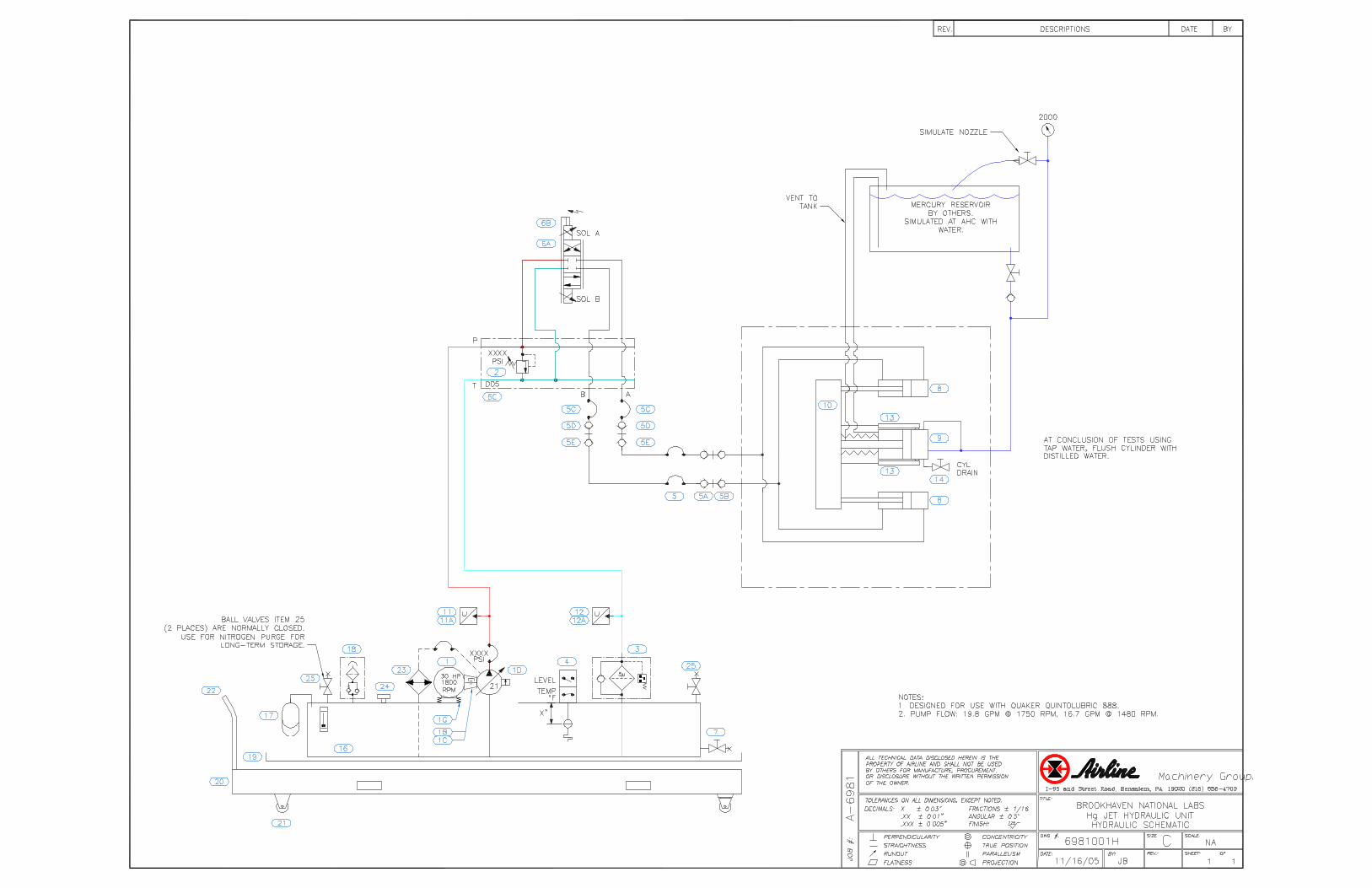
Given: Hg cylinder is 10" boreFlow rate required: 25 gpmInduced pressure required: 1500 psiDrive cylinders are (2) 6" bore x 2.5" rodsProportional valve = 4WREE10E50Pump = 45cc piston pump, pressure comp.
Calculations Area of 10" bore = 78.54 in2
Velocity to produce 25 gpm nominal 25(231)/78.54 = 73.53 in/min = 1.2255 in/sec
Velocity to produce 30 gpm max 30(1.2255)/25 = 1.4706 in/sec
Drive cylinder net area = 23.37 in2Area ration = 1.21:1
Flow req'd for 1.2255 in/sec, Q =Q= 1.2255(23.37)(60/231) = 7.44 gpm
Total Q = 14.88 gpm (for 25 gpm Hg)
Return flow rate from drive cylindersQout = 1.21 (14.88) = 18 gpm
For 30 gpm Hg, Q = 14.88 (30/25) = 17.86 gpm
NOTE: Potential for 45cc pump at 1480 rpm and 95% vol eff = 16.7 gpm. This give ability to induce only Vel = 16.7gpm * 231in3/gal / 60 s/min / 23.37 in2 / 2cylVel = 1.3756 in/sec QHg @ 1.3756 in/sec = 1.3756 (78.54 in2) (60/231)
Q Hgmax = 28.06 gpm Hg when pump @ 1480 rpm
Calculate system pressure req'd to induce 1500 psi HgForce @ Hg cyl = 78.54 in2 * 1500 psi = 117,810 lbs
Drive cyl net area = 23.37 in2 x 2 cyl = 46.74 in2
Pressure @ drive cyl = 117,810 lbs / 46.74 in2 =
P = 2520 psi required at cylinders.
Estimate pressure drops at about 21 gpm: PSI Prop valve @ 100% open: 400

Hoses - rod side 25 Hoses - blind side 50 Filter 15 Misc fittings 30
Total estimated pressure drop at velocity = 520 psi 520
System pressure as set at pump compensator Psys = 2520 psi @ cyl + 520 psi flow losses
Psys = 3039 psi
Calculate drive power requiredHP = 3039 psi * 14.88 gpm / (1714 * .85eff)
HP = 31.03 HP @ 25 gpm Hg flow (peak)
HP = 3039 psi * 16.7 gpm / (1714 * .85 eff)
HP = 34.8 HP @ 28 gpm Hg flow (peak)
Determine Peak power draw in USA @ 1750 rpmPump flow potential 20.8 gpm at 100% vol eff, 1750 rpm
HP = 20.8 (3039) / (1714*.95 eff mech) = 38.8 HP peak
Note, this would be 129% of rated 30 HP motor


C-1
Appendix C. Primary Containment Documents

MERIT Calculation SheetOak Ridge National Laboratory
safety factor for pressure loadingFS 136.455=FSSyσ
:=
σ 293.137 psi=
stress at centerσ6Mc
t2:=
moment at centerMcq a2⋅ 1 ν+( )⋅
16:=
yc 1.984− 10 5−× in=
deflection at centerycq− a4⋅
64D:=
plate constantDE t3⋅
12 1 ν2
−( )⋅
:=
pressure loadingq 15psi:=
viewport thicknesst 0.236in:=
outer radius of unsupported viewporta 1.5in:=
tensile yield strength sapphireSy 40000psi:=
modulus of elasticityE 50 106psi⋅:=
Poissons ratioν 0.29:=
The primary containment system may be run under vacuum conditions or may be pressurizedduring leak testing operations. This calculation checks the integrity of the sapphire viewportsunder 1atm pressure. Calculations based on Roark's Formulas for Stress and Strain, 6th edition,Flat Plates case 10b.
DATE 12 Apr 2006 CALCULATION BY V. Graves
DRAWING NO 203-HJT-0630
SHEET 1 OF 1 CALCULATION Optical Viewport Stresses in Pressure Testing
1
MERIT Calculation SheetOak Ridge National Laboratory
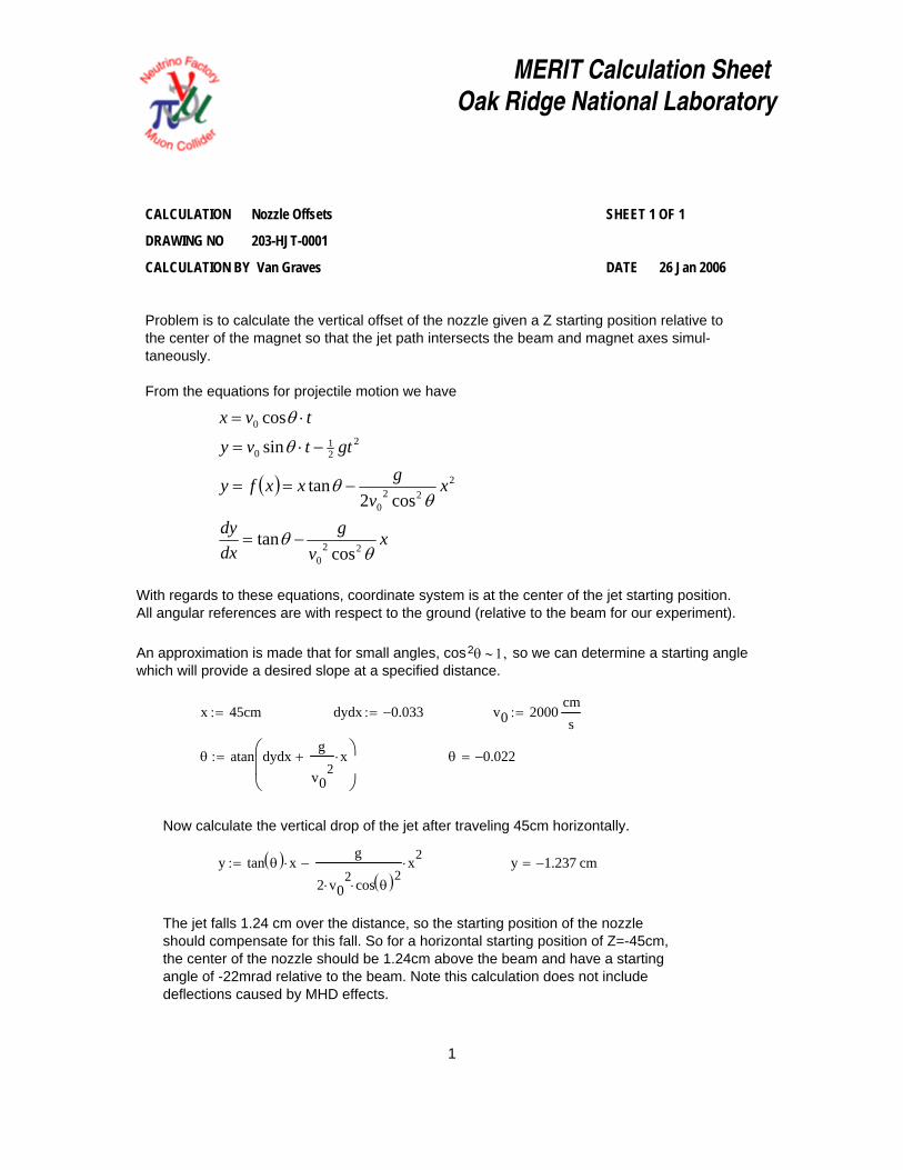
The jet falls 1.24 cm over the distance, so the starting position of the nozzleshould compensate for this fall. So for a horizontal starting position of Z=-45cm,the center of the nozzle should be 1.24cm above the beam and have a startingangle of -22mrad relative to the beam. Note this calculation does not includedeflections caused by MHD effects.
y 1.237− cm=y tan θ( ) x⋅g
2 v02
⋅ cos θ( )2⋅
x2⋅−:=
Now calculate the vertical drop of the jet after traveling 45cm horizontally.
θ 0.022−=θ atan dydxg
v02
x⋅+⎛⎜⎜⎝
⎞⎟⎟⎠
:=
v0 2000cms
:=dydx 0.033−:=x 45cm:=
With regards to these equations, coordinate system is at the center of the jet starting position.All angular references are with respect to the ground (relative to the beam for our experiment).
An approximation is made that for small angles, cos2θ ∼ 1, so we can determine a starting anglewhich will provide a desired slope at a specified distance.
( )
xv
gdxdy
xv
gxxfy
gttvy
tvx
θθ
θθ
θ
θ
220
222
0
221
0
0
costan
cos2tan
sin
cos
−=
−==
−⋅=
⋅=
Problem is to calculate the vertical offset of the nozzle given a Z starting position relative tothe center of the magnet so that the jet path intersects the beam and magnet axes simul-taneously.
From the equations for projectile motion we have
DATE 26 Jan 2006 CALCULATION BY Van Graves
DRAWING NO 203-HJT-0001
SHEET 1 OF 1 CALCULATION Nozzle Offsets
1
MERIT Calculation SheetOak Ridge National Laboratory
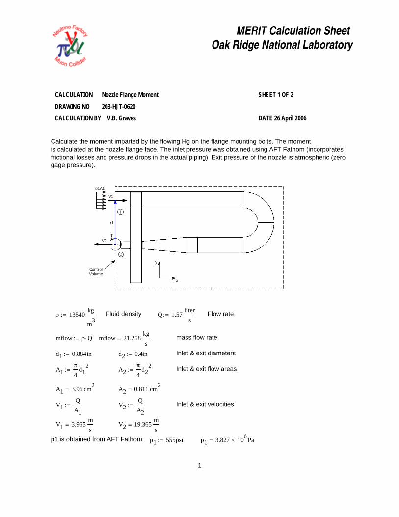
p1 3.827 106× Pa=p1 555psi:=p1 is obtained from AFT Fathom:
V2 19.365ms
=V1 3.965ms
=
Inlet & exit velocitiesV2QA2
:=V1QA1
:=
A2 0.811 cm2=A1 3.96 cm2
=
Inlet & exit flow areasA2π
4d2
2:=A1
π
4d1
2:=
Inlet & exit diametersd2 0.4in:=d1 0.884in:=
mass flow ratemflow 21.258kgs
=mflow ρ Q⋅:=
Flow rateQ 1.57liter
s:=Fluid densityρ 13540
kg
m3:=
1
V1
V2
2
ControlVolume
y
x
p1A1
O
T
r1
Calculate the moment imparted by the flowing Hg on the flange mounting bolts. The momentis calculated at the nozzle flange face. The inlet pressure was obtained using AFT Fathom (incorporatesfrictional losses and pressure drops in the actual piping). Exit pressure of the nozzle is atmospheric (zerogage pressure).
DATE 26 April 2006 CALCULATION BY V.B. Graves
DRAWING NO 203-HJT-0620
SHEET 1 OF 2 CALCULATION Nozzle Flange Moment
1

MERIT Calculation SheetOak Ridge National Laboratory
CALCULATION Nozzle Flange Moment SHEET 2 OF 2
DRAWING NO 203-HJT-0620
CALCULATION BY V.B. Graves DATE 26 April 2006
For an inertial, non-deformable control volume with 1-dimensional inlets & outlets, conservationof angular momentum states that
( ) ( ) ( )
( ) ( )( )
( )1111
11111
111111
VmAprTVrmrApT
mAp
mmdtd
O
O
inO
ininoutoutOOO
&
&
&
&&
+=+=−
−×=−×+
×−×=×== ∑∑ ∑ ∑VrnrT
VrVrFrMH
r1 3in:= To r1 p1 A1 mflow V1⋅+( )⋅:=
To 89.9 ft lbf⋅= To 121.9 N m⋅=
2

MERIT Calculation SheetOak Ridge National Laboratory
V2 19.365ms
=V1 3.965ms
=
Inlet & exit velocitiesV2QA2
:=V1QA1
:=
A2 0.811 cm2=A1 3.96 cm2
=
Inlet & exit flow areasA2π
4d2
2:=A1
π
4d1
2:=
Inlet & exit diametersd2 0.4in:=d1 0.884in:=
mass flow ratemass 21.258kgs
=mass ρ Q⋅:=
Flow rateQ 1.57liter
s:=Fluid densityρ 13540
kg
m3:=
1
V1
V2
2
ControlVolume
y
x
p1A1
F
Calculate the forces imparted by the flowing Hg on the flange mounting bolts. The forceis calculated at the nozzle. A reference calculation of the inlet pressure is made usingBernoulli's equation, but the inlet pressure calculated using AFT Fathom (incorporatesfrictional losses and pressure drops in the actual piping) is used for subsequent forcecalculations. Exit pressure of the nozzle is atmospheric (zero gage pressure).
DATE 26 April 2006 CALCULATION BY V.B. Graves
DRAWING NO 203-HJT-0620
SHEET 1 OF 2 CALCULATION Nozzle Flange Axial Force
1

MERIT Calculation SheetOak Ridge National Laboratory
Safety FactorFS 27.094=FSσyσact
:=
σact 2.584 103× psi=σact
F10At
:=
yield strengthσy 70000psi:=
shcs thread stress areaAt 0.0175in2:=
The nozzle flange is attached with ten SS 18-8 #10-24 socket head cap screws. If the system werecompletely rigid, the stress seen in the screws due to the axial force would be
F 2011 N=F 452 lbf=F p1 A1⋅ mass V2 V1+( )⋅+:=
mass V2 V1+( )⋅ 111 lbf=p1 A1⋅ 341 lbf=
)()()(
1211
121211
VVmApFVVmmFApx
++=
−−=−=−=∑&
&& VVF
A control volume analysis provides the resultant force
p1 3.827 106× Pa=p1 555psi:=A more accurate value of p1 is obtained from AFT Fathom:
p1ref 2.43 106× Pa=p1ref 353 psi=p1ref
12ρ V2
2 V12
−⎛⎝
⎞⎠⋅:=
Reference pressure at 1 is given by Bernoulli's equation:
DATE 26 April 2006 CALCULATION BY V.B. Graves
DRAWING NO 203-HJT-0620
SHEET 2 OF 2 CALCULATION Nozzle Flange Axial Force
2

MERIT Calculation SheetOak Ridge National Laboratory
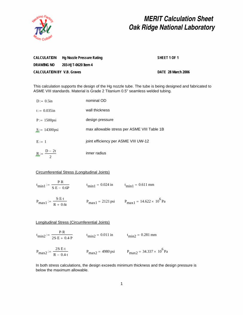
RD 2t−
2:= inner radius
Circumferential Stress (Longitudinal Joints)
tmin1P R⋅
S E⋅ 0.6P−:= tmin1 0.059 in= tmin1 1.504 mm=
Pmax1S E⋅ t⋅
R 0.6t+:= Pmax1 2042 psi= Pmax1 14.08 106
× Pa=
Longitudinal Stress (Circumferential Joints)
tmin2P R⋅
2S E⋅ 0.4P+:= tmin2 0.027 in= tmin2 0.679 mm=
Pmax22S E⋅ t⋅
R 0.4t−:= Pmax2 4913 psi= Pmax2 33.877 106
× Pa=
In both stress calculations, the design exceeds minimum thickness and the design pressure isbelow the maximum allowable.
CALCULATION Hg Supply Line Pressure Rating SHEET 1 OF 1
DRAWING NO 203-HJT-0620 Item 2
CALCULATION BY V.B. Graves DATE 28 March 2006
This calculation supports the design of the Hg supply feedline that is between the flexiblehose and the reducer. The feedline is being designed and fabricated to ASME VIII standards.Material is Grade 2 Titanium welded pipe. Nominal design is 3/4" SCH10 pipe.
D 1.05in:= nominal OD for 3/4" pipe
t 0.083in:= wall thickness for Sch 10
P 1500psi:= design pressure
S 12100psi:= max allowable stress per ASME VIII Table 1B
E 1:= joint efficiency per ASME VIII UW-12
5/25/2006 1
MERIT Calculation SheetOak Ridge National Laboratory
RD 2t−
2:= inner radius
Circumferential Stress (Longitudinal Joints)
tmin1P R⋅
S E⋅ 0.6P−:= tmin1 0.024 in= tmin1 0.611 mm=
Pmax1S E⋅ t⋅
R 0.6t+:= Pmax1 2121 psi= Pmax1 14.622 106
× Pa=
Longitudinal Stress (Circumferential Joints)
tmin2P R⋅
2S E⋅ 0.4 P⋅+:= tmin2 0.011 in= tmin2 0.281 mm=
Pmax22S E⋅ t⋅
R 0.4 t⋅−:= Pmax2 4980 psi= Pmax2 34.337 106
× Pa=
In both stress calculations, the design exceeds minimum thickness and the design pressure isbelow the maximum allowable.
CALCULATION Hg Nozzle Pressure Rating SHEET 1 OF 1
DRAWING NO 203-HJT-0620 Item 4
CALCULATION BY V.B. Graves DATE 28 March 2006
This calculation supports the design of the Hg nozzle tube. The tube is being designed and fabricated toASME VIII standards. Material is Grade 2 Titanium 0.5" seamless welded tubing.
D 0.5in:= nominal OD
t 0.035in:= wall thickness
P 1500psi:= design pressure
S 14300psi:= max allowable stress per ASME VIII Table 1B
E 1:= joint efficiency per ASME VIII UW-12
1

MERIT Calculation SheetOak Ridge National Laboratory
joint efficiency per ASME VIII UW-12
R1D1 2t1−
2:= R2
D2 2t2−
2:= inner radii
Circumferential Stress (Longitudinal Joints) 3/4" pipe
tmin1P R1⋅
S E⋅ 0.6P−:= tmin1 0.046 in= tmin1 1.18 mm=
Pmax1S E⋅ t1⋅
R1 0.6t1+:= Pmax1 3344 psi= Pmax1 23.058 106
× Pa=
Longitudinal Stress (Circumferential Joints) 3/4" pipe
tmin2P R1⋅
2S E⋅ 0.4P+:= tmin2 0.021 in= tmin2 0.541 mm=
Pmax22S E⋅ t1⋅
R1 0.4t1−:= Pmax2 8749 psi= Pmax2 60.323 106
× Pa=
CALCULATION Hg Supply Line Pressure Rating SHEET 1 OF 2
DRAWING NO 203-HJT-0670, -0680
CALCULATION BY V.B. Graves DATE 20 April 2006
This calculation supports the design of the piping that acts as the inlet and outlet from the Hgcylinder. These lines are being designed and fabricated to ASME VIII standards. Material is 3/4" and 1"SCH40 SS304L welded pipe.
D1 1.05in:= D2 1.315in:= nominal OD for 3/4" & 1" pipe
t1 0.113in:= t2 0.133in:= wall thickness for 3/4" & 1" Sch 40
P 1500psi:= design pressure
S 14200psi:= max allowable stress per ASME VIII Table 1A
E 1:=
1

MERIT Calculation SheetOak Ridge National Laboratory
Pmax4 55.258 106× Pa=Pmax4 8014 psi=Pmax4
2S E⋅ t2⋅
R2 0.4t2−:=
tmin4 0.689 mm=tmin4 0.027 in=tmin4P R2⋅
2S E⋅ 0.4P+:=
Longitudinal Stress (Circumferential Joints) 1" pipe
Pmax3 21.548 106× Pa=Pmax3 3125 psi=Pmax3
S E⋅ t2⋅
R2 0.6t2+:=
tmin3 1.503 mm=tmin3 0.059 in=tmin3P R2⋅
S E⋅ 0.6P−:=
Circumferential Stress (Longitudinal Joints) 1" pipe
DATE 20 April 2006 CALCULATION BY V.B. Graves
DRAWING NO 203-HJT-0670, -0680
SHEET 2 OF 2 CALCULATION Hg Supply Line Pressure Rating
2

MERIT Calculation SheetOak Ridge National Laboratory
Rx 425.372 N= Rx 95.627 lbf=
To calculate the minimum deflector thickness, assume force acts in center of deflectorand that the ends are rigidly supported.
Sy 120000psi:= tensile yield strength of Ti6AlV4
Plate dimensions: w 2in:= len 6in:= t 2mm:= ct2
:=
Moment of inertia: I112
w⋅ t3⋅:=
Shear VRx2
:= τ32
Vw t⋅⋅:= τ 455.425 psi=
MRx len⋅
8:= σact
M c⋅I
:= σact 3.47 104× psi= FS
Syσact
:= FS 3.458=
CALCULATION Deflector Forces SHEET 1 OF 1
DRAWING NO 203-HJT-0616
CALCULATION BY V.B. Graves DATE 5 Jan 2005
Calculate the force of the Hg jet on the deflector plate, which also serves as the downstreamprimary beam window. Material is Ti6Al4V.
ρ 13540kg
m3:= ρ 845.275
lb
ft3=
dnozzle 1cm:= Ajetπ
4dnozzle
2⋅:= Ajet 0.785 cm2
=
Vjet 20ms
:= Q Ajet Vjet⋅:= Q 1.571Ls
= Q 24.898galmin
=
mjet ρ Q⋅:= mjet 21.269masstime
= mjet 46.889lbs
=
Assume deflector is vertical and jet is horizontal to simplify calculation - very conservativeassumption. Hg spray will be evenly distributed in all directions, so vertical component ofresultant force will be cancelled.
Rx mjet Vjet⋅:=
1

MERIT Calculation SheetOak Ridge National Laboratory
offsetsr2 2.25in:=r1 1in:=
p2 3.944 106× Pa=p2 572psi:=
pressures obtained from AFT Fathomp1 3.985 106× Pa=p1 578psi:=
Flow area & velocityV 3.965ms
=VQA
:=Aπ
4d2
:=
Inlet & exit diameters are equald 0.884in:=
mass flow ratemflow 21.258kgs
=mflow ρ Q⋅:=
Flow rateQ 1.57liter
s:=Fluid densityρ 13540
kg
m3:=
1
V1
V2
2
ControlVolume
y
x
OT
r1p2A2
p1A1p1A1
r2
Calculate the moment imparted by the flowing Hg on the first piping restraint, assuming rigid connection.The fluid pressures were obtained using AFT Fathom so as to incorporate frictional losses and pressuredrops in the actual piping.
DATE 10 May 2006 CALCULATION BY V.B. Graves
DRAWING NO 203-HJT-0623
SHEET 1 OF 2 CALCULATION Hg Supply Piping Moment
1

MERIT Calculation SheetOak Ridge National Laboratory
CALCULATION Hg Supply Piping Moment SHEET 2 OF 2
DRAWING NO 203-HJT-0623
CALCULATION BY V.B. Graves DATE 10 May 2006
For an inertial, non-deformable control volume with 1-dimensional inlets & outlets, conservationof angular momentum states that
( ) ( ) ( )
( ) ( ) ( )( ) ( )( )
)()()(
221112
122211
112222221111
prprArrVmTrrVmAprAprT
mmApAp
mmdtd
O
O
inoutO
ininoutoutOOO
−+−=−=+−
×−×=−×+−×+
×−×=×== ∑∑ ∑ ∑
&
&
&&
&&
VrVrnrnrT
VrVrFrMH
To mflow V⋅ r2 r1−( )⋅ A r1 p1⋅ r2 p2⋅−( )⋅+:= mflow V⋅ r2 r1−( )⋅ 1.974 ft lbf⋅=
A r1 p1⋅ r2 p2⋅−( )⋅ 36.263− ft lbf⋅=
To 34.3− ft lbf⋅= To 46.5− N m⋅=
2

Stress Analysis of Hg Sump Tank - Hg Weight
Author: V.B. Graves
Company: Oak Ridge National Laboratory
Date: Nov 15, 2005
1. Introduction 2. Materials 3. Load & Restraint Information 4. Study Property 5. Stress Results 6. Displacement Results 7. Design Check Results 8. Conclusion 9. Appendix
1. Introduction A static analysis of the Hg sump tank is performed. Loading condition is 800 lb applied to bottom of tank to simulate weight of 23 liters Hg. No loads on the side walls were simulated.

Areas representing the square supports on the tank bottom were restrained.
Note:
Do not base your design decisions solely on the data presented in this report. Use this information in conjunction with experimental data and practical experience. Field testing is mandatory to validate your final design. COSMOSWorks helps you reduce your time-to-market by reducing but not eliminating field tests.
2. Materials
No. Part Name Material Mass Volume 1 sump tank hjt AISI 304 59.5098 lb 205.903 in^3 2 sump tank hjt AISI 304 59.5098 lb 205.903 in^3 3 sump tank hjt AISI 304 59.5098 lb 205.903 in^3
3. Load & Restraint Information
Restraint Restraint-1 <sump tank hjt>
on 2 Face(s) fixed.
Description: Tank bottom restrained where it contacts supports.
Load Force-1 <sump tank hjt>
on 1 Face(s) apply normal force 800 lb using uniform distribution
Sequential Loading
Description: Weight of 23 liters Hg applied to

bottom face.
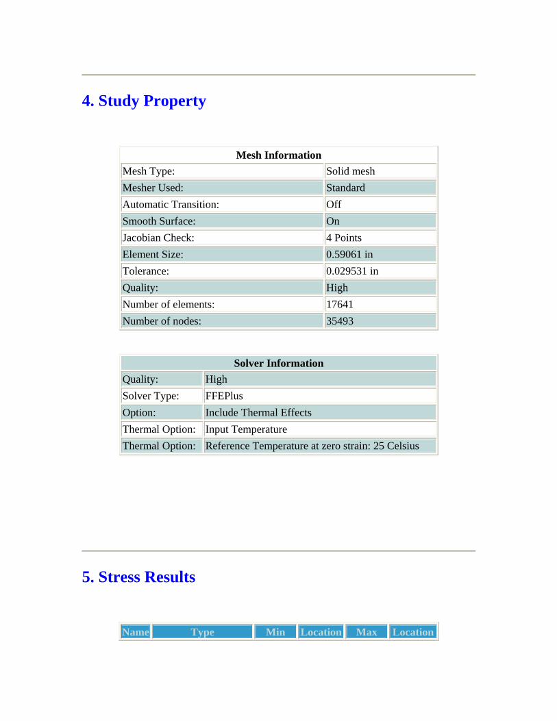
4. Study Property
Mesh Information Mesh Type: Solid mesh Mesher Used: Standard Automatic Transition: Off Smooth Surface: On Jacobian Check: 4 Points Element Size: 0.59061 in Tolerance: 0.029531 in Quality: High Number of elements: 17641 Number of nodes: 35493
Solver Information Quality: High Solver Type: FFEPlus Option: Include Thermal Effects Thermal Option: Input Temperature Thermal Option: Reference Temperature at zero strain: 25 Celsius
5. Stress Results

Name Type Min Location Max Location
Plot1 VON: von Mises stress
1.52968 psi Node: 25974
(7.50297 in, 0 in, -3.2 in)
867.968 psi Node: 27866
(-9.71311 in, 0.125 in, 2.37814 in)
sump tank hjt-HgWeight-Stress-Plot1
JPEG

6. Displacement Results
Name Type Min Location Max Location
Plot1 URES: Resultant displacement
0 in Node:
(9.18681 in,
0.00103167 in
(1.34711e-015 in,
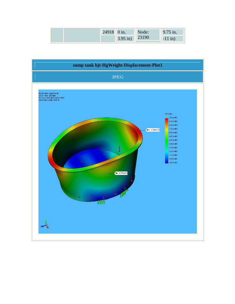
24918 0 in, 3.95 in)
Node: 23190
9.75 in, -11 in)
sump tank hjt-HgWeight-Displacement-Plot1
JPEG

7. Design Check Results
sump tank hjt-HgWeight-Design Check-Plot1
JPEG

8. Conclusion Analysis shows minimum safety factor > 30, so tank is considered structurally sound for this loading condition.
9. Appendix
Material name: AISI 304
Description:
Material Source: Library files
Material Library Name: cosmos materials
Material Model Type: Linear Elastic Isotropic
Property Name Value Units Value Type Elastic modulus 2.7557e+007 psi Constant Poisson's ratio 0.29 NA Constant Shear modulus 1.0878e+007 psi Constant Mass density 0.28902 lb/in^3 Constant Tensile strength 74987 psi Constant Yield strength 29995 psi Constant Thermal expansion coefficient 1e-005 /Fahrenheit Constant Thermal conductivity 0.000214 BTU/(in.s.F) Constant Specific heat 0.11945 Btu/(lb.F) Constant

Stress Analysis of Hg Jet Chamber
Author: V.B. Graves
Company: Oak Ridge National Laboratory
Date: May 19, 2006
1. Introduction 2. Materials 3. Load & Restraint Information 4. Study Property 5. Stress Results 6. Displacement Results 7. Design Check Results 8. Conclusion 9. Appendix
1. Introduction A static analysis of the Hg jet chamber is performed. The chamber may be tested prior to Hg loading either by a static pressure test or a vacuum rate-of-rise test. A static internal pressure of 1atm was simulated in this analysis. During operation there will be no interior pressure within the weldment.
Note:

Do not base your design decisions solely on the data presented in this report. Use this information in conjunction with experimental data and practical experience. Field testing is mandatory to validate your final design. COSMOSWorks helps you reduce your time-to-market by reducing but not eliminating field tests.
2. Materials
No. Part Name Material Mass Volume 1 pri tube weldment hjt AISI 304 44.7162 lb 154.718 in^3 2 pri tube weldment hjt AISI 304 44.7162 lb 154.718 in^3 3 pri tube weldment hjt AISI 304 44.7162 lb 154.718 in^3 4 pri tube weldment hjt AISI 304 44.7162 lb 154.718 in^3 5 pri tube weldment hjt AISI 304 44.7162 lb 154.718 in^3 6 pri tube weldment hjt AISI 304 44.7162 lb 154.718 in^3
3. Load & Restraint Information
Restraint Restraint-1 <pri tube weldment hjt>
on 1 Face(s) fixed.
Description: Exit end face held fixed.
Load Pressure-1 <pri tube weldment hjt>
on 10 Face(s) with Pressure 15 psi along direction normal to selected face Sequential
Loading
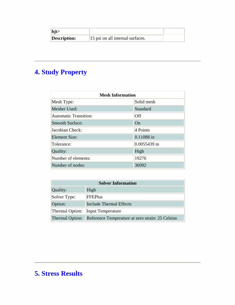
Description: 15 psi on all internal surfaces.

4. Study Property
Mesh Information Mesh Type: Solid mesh Mesher Used: Standard Automatic Transition: Off Smooth Surface: On Jacobian Check: 4 Points Element Size: 0.53695 in Tolerance: 0.026848 in Quality: High Number of elements: 14806 Number of nodes: 30039
Solver Information Quality: High Solver Type: FFEPlus Option: Include Thermal Effects Thermal Option: Input Temperature Thermal Option: Reference Temperature at zero strain: 25 Celsius
5. Stress Results

Name Type Min Location Max Location
Plot1 VON: von Mises stress
10.3982 psi Node: 693
(1.25 in,-2.6625 in, -18.0992 in)
20466.5 psi Node: 5620
(0.658211 in, 2.21623 in, 25.9439 in)
pri tube weldment hjt-Pressure1atm-Stress-Plot1
JPEG

6. Displacement Results
Name Type Min Location Max Location
Plot1 URES: Resultant displacement
0 in Node: 1440
(-0.6875 in, 0.645291 in, 34 in)
0.0023928 in Node: 16816
(-0.8125 in, 1.88444 in, 28.9516 in)
pri tube weldment hjt-Pressure1atm-Displacement-Plot1
JPEG

7. Design Check Results
pri tube weldment hjt-Pressure1atm-Design Check-Plot1
JPEG

8. Conclusion Analysis indicates minimum safety factor > 10, so structure is considered structurally sound for the simulated loading condition.

9. Appendix
Material name: AISI 304
Description:
Material Source: Library files
Material Library Name: cosmos materials
Material Model Type: Linear Elastic Isotropic
Property Name Value Units Value Type Elastic modulus 2.7557e+007 psi Constant Poisson's ratio 0.29 NA Constant Shear modulus 1.0878e+007 psi Constant Mass density 0.28902 lb/in^3 Constant Tensile strength 74987 psi Constant Yield strength 29995 psi Constant Thermal expansion coefficient 1e-005 /Fahrenheit Constant Thermal conductivity 0.000214 BTU/(in.s.F) Constant Specific heat 0.11945 Btu/(lb.F) Constant

Stress Analysis of Hg Supply Reducer
Author: Author: Van Graves
Company: Oak Ridge National Laboratory
Date: April 12, 2006
1. Introduction 2. Materials 3. Load & Restraint Information 4. Study Property 5. Stress Results 6. Displacement Results 7. Design Check Results 8. Conclusion 9. Appendix
1. Introduction A static analysis of the Hg flow reducer is performed. The design pressure of 1500 psi was applied to the interior surfaces of the reducer.
Note:
Do not base your design decisions solely on the data presented in this report. Use this information in conjunction with experimental data and practical experience. Field testing

is mandatory to validate your final design. COSMOSWorks helps you reduce your time-to-market by reducing but not eliminating field tests.
2. Materials
No. Part Name Material Mass Volume
1 hg supply reducer hjt
Titanium Ti-6Al-4V (Grade 5), Annealed
0.0998634 lb
0.623975 in^3
3. Load & Restraint Information
Restraint Restraint-1 <hg supply reducer hjt>
on 2 Face(s) fixed.
Description: Outer diameter and face of exit end fixed as they would be welded to the nozzle flange.
Load Pressure-1 <hg supply reducer hjt>
on 3 Face(s) with Pressure 1500 psi along direction normal to selected face Sequential
Loading
Description: Design pressure load.
4. Study Property

Mesh Information Mesh Type: Solid mesh Mesher Used: Standard Automatic Transition: Off Smooth Surface: On Jacobian Check: 4 Points Element Size: 0.085485 in Tolerance: 0.0042742 in Quality: High Number of elements: 7612 Number of nodes: 15263
Solver Information Quality: High Solver Type: FFE Option: Include Thermal Effects Thermal Option: Input Temperature Thermal Option: Reference Temperature at zero strain: 77 Fahrenheit
5. Stress Results
Name Type Min Location Max Location
Plot1 VON: von Mises stress
2.56573 psi Node: 2509
(0.375 in, -0.249301 in, 0.0186825
13665.3 psi Node: 14939
(-0.041552 in, 0.244426

in) in, 0.0683738 in)
hg supply reducer hjt-1500psi-Stress-Plot1
JPEG

6. Displacement Results
Name Type Min Location Max Location
Plot1 URES: Resultant displacement
0 in Node: 1
(0.375 in, 0.216506 in, -0.125 in)
0.00117264 in Node: 2032
(-3.625 in, 0.41769 in, -0.144564 in)
hg supply reducer hjt-1500psi-Displacement-Plot1
JPEG

7. Design Check Results
hg supply reducer hjt-1500psi-Design Check-Plot1
JPEG

8. Conclusion The flow reducer should never actually encounter the full design pressure since the downstream pressure drop is due to the nozzle, which requires about 400 psi. With a minimum safety factor > 9 for the design case, the reducer is considered structurally safe

for the simulated loading condition.
9. Appendix
Material name: Titanium Ti-6Al-4V (Grade 5), Annealed
Description:
Material Source: Library files
Material Library Name: titanium
Material Model Type: Linear Elastic Isotropic
Property Name Value Units Value Type Elastic modulus 1.6505e+007 psi Constant Elastic modulus 1.6505e+007 psi Constant Elastic modulus 1.6505e+007 psi Constant Poisson's ratio 0.342 NA Constant Poisson's ratio 0.342 NA Constant Poisson's ratio 0.342 NA Constant Shear modulus 6.3817e+006 psi Constant Shear modulus 6.3817e+006 psi Constant Shear modulus 6.3817e+006 psi Constant Mass density 0.16004 lb/in^3 Constant Tensile strength 1.3779e+005 psi Constant Compressive strength 1.4069e+005 psi Constant Yield strength 1.2763e+005 psi Constant Thermal expansion coefficient 4.7778e-006 /Fahrenheit Constant Thermal expansion coefficient 4.7778e-006 /Fahrenheit Constant Thermal expansion coefficient 4.7778e-006 /Fahrenheit Constant Thermal conductivity 8.9611e-005 BTU/(in.s.F) Constant Thermal conductivity 8.9611e-005 BTU/(in.s.F) Constant Specific heat 0.12573 Btu/(lb.F) Constant

Stress Analysis of Hg Sump Tank - Internal Pressure
Author: V.B. Graves
Company: Oak Ridge National Laboratory
Date: Nov 15, 2005
1. Introduction 2. Materials 3. Load & Restraint Information 4. Study Property 5. Stress Results 6. Displacement Results 7. Design Check Results 8. Conclusion 9. Appendix
1. Introduction A static analysis of the Hg sump tank is performed. Loading condition is 1atm internal pressure applied to bottom and wall of tank to simulate leak check operation. Areas representing the square supports on the tank bottom were restrained.

Note:
Do not base your design decisions solely on the data presented in this report. Use this information in conjunction with experimental data and practical experience. Field testing is mandatory to validate your final design. COSMOSWorks helps you reduce your time-to-market by reducing but not eliminating field tests.
2. Materials
No. Part Name Material Mass Volume 1 sump tank hjt AISI 304 59.5098 lb 205.903 in^3 2 sump tank hjt AISI 304 59.5098 lb 205.903 in^3 3 sump tank hjt AISI 304 59.5098 lb 205.903 in^3
3. Load & Restraint Information
Restraint Restraint-1 <sump tank hjt>
on 2 Face(s) fixed.
Description: Tank bottom restrained where it contacts supports.
Load Pressure-1 <sump tank hjt>
on 2 Face(s) with Pressure 15 psi along direction normal to selected face
Sequential Loading
Description: 15 psi internal pressure on bottom and wall.
4. Study Property
Mesh Information Mesh Type: Solid mesh Mesher Used: Standard Automatic Transition: Off Smooth Surface: On Jacobian Check: 4 Points Element Size: 0.59061 in Tolerance: 0.029531 in Quality: High Number of elements: 17641 Number of nodes: 35493
Solver Information Quality: High Solver Type: FFEPlus Option: Include Thermal Effects Thermal Option: Input Temperature Thermal Option: Reference Temperature at zero strain: 25 Celsius
5. Stress Results
Name Type Min Location Max Location
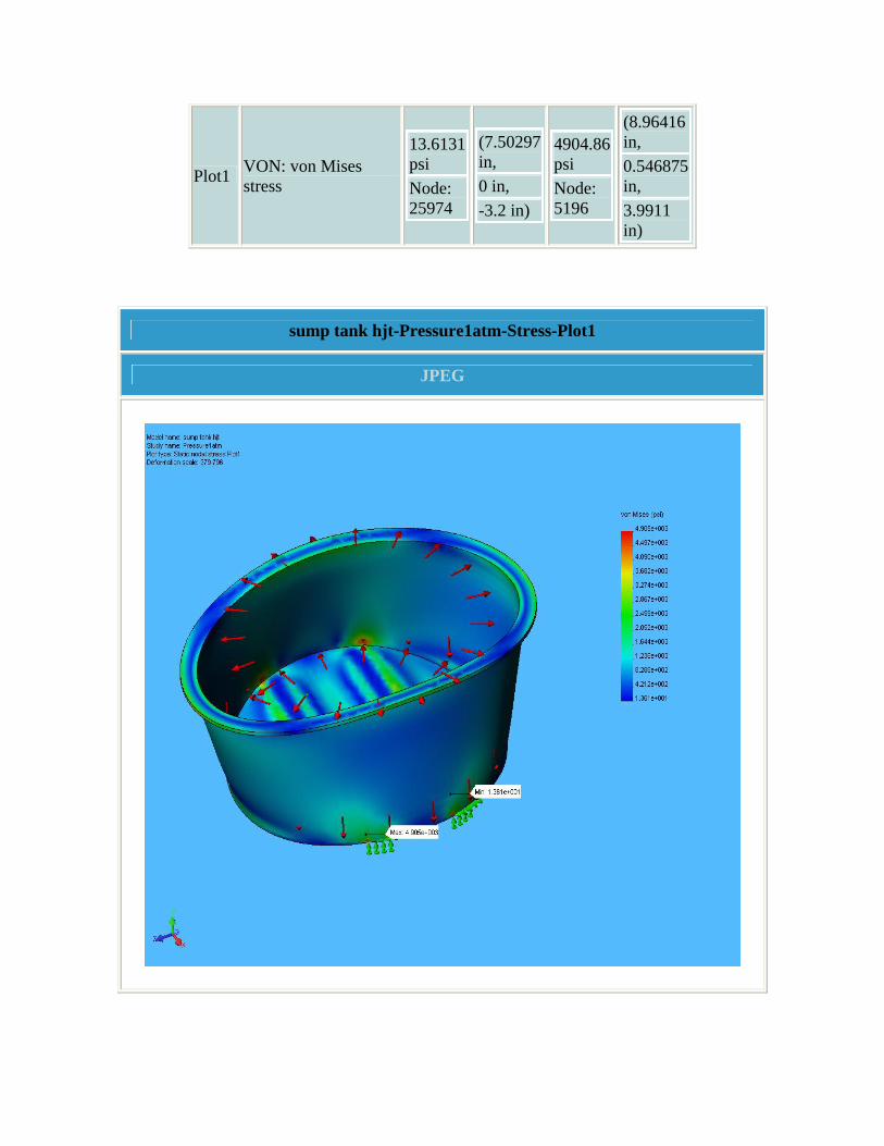
Plot1 VON: von Mises stress
13.6131 psi Node: 25974
(7.50297 in, 0 in, -3.2 in)
4904.86 psi Node: 5196
(8.96416 in, 0.546875 in, 3.9911 in)
sump tank hjt-Pressure1atm-Stress-Plot1
JPEG

6. Displacement Results
Name Type Min Location Max Location
Plot1 URES: Resultant displacement
0 in Node: 24918
(9.18681 in, 0 in, 3.95 in)
0.00657775 in Node: 21565
(0 in, 9.21094 in, -10 in)
sump tank hjt-Pressure1atm-Displacement-Plot1
JPEG

7. Design Check Results
sump tank hjt-Pressure1atm-Design Check-Plot1
JPEG

8. Conclusion Area of highest stress near tank bottom close to support. Minimum safety factor > 6, so tank is considered structurally sound for this loading condition.

9. Appendix
Material name: AISI 304
Description:
Material Source: Library files
Material Library Name: cosmos materials
Material Model Type: Linear Elastic Isotropic
Property Name Value Units Value Type Elastic modulus 2.7557e+007 psi Constant Poisson's ratio 0.29 NA Constant Shear modulus 1.0878e+007 psi Constant Mass density 0.28902 lb/in^3 Constant Tensile strength 74987 psi Constant Yield strength 29995 psi Constant Thermal expansion coefficient 1e-005 /Fahrenheit Constant Thermal conductivity 0.000214 BTU/(in.s.F) Constant Specific heat 0.11945 Btu/(lb.F) Constant

D-1
Appendix D. Secondary Containment Documents

Mercury Removal From Gas Streams
835 N. Cassady Ave. • Columbus, OH •43219• 1-800-886-2272 • 614-258-9501• Fax 614-258-3464 • E-mail: [email protected] • www.bscarbons.com Rocky Mountain Office • Reno, NV • 775-355-7770 • Fax 775-355-7785 / Western Regional Office • Los Angeles, CA • 562-802-3400 • Fax 562-802-3480 Gulf Coast Office• Sulfur, LA • 337-527-0084 • Fax 337-527-0087 / Northeast Regional Office • Downingtown, PA • 610- 870-3070 • Fax 610-870-3072 T-1333
Mercury Issues
Because of the extreme toxicity of mercury vapor, removal of mercury from air and process gas stream is critical for both safety and environmental compliance. The threshold limit value (TLV) for mercury exposure is 0.05 mg/m3. In addition, the presence of trace mercury in process gas streams (e.g. natural gas, hydrogen) can lead to significant process problems, such as corrosion and catalyst poisoning. Barnebey Sutcliffe provides three different products for vapor phase mercury control for different applications: activated carbon types CB, CBII, and CY. These products can reduce mercury to part per trillion levels and can achieve capacities as high as 20% by weight.
Development of CB Carbon
Virgin activated carbon has a relatively low capacity for mercury vapors. In 1960, Barnebey Sutcliffe developed the first generation of impregnated carbon to remove Hg. This product used potassium iodide (KI) and iodine (I3) to react with mercury according to the following reaction:
3 Hg + I3 3 HgI
Barnebey Sutcliffe today offers an improved version of this product under the trade name Type CB. It is used for specialty applications, such as H2 purification because it is resistant to side reactions (H2S formation).
Type CBII Carbon
Sulfur has long been known to be effective in removing mercury vapor via the following reaction:
Hg + S HgS
Barnebey Sutcliffe has developed a proprietary process for impregnation of carbon with sulfur and carbon base materials that provided optimum pore structure for mercury capture. Using this technology Barnebey Sutcliffe markets a sulfur-impregnated product under the trade name CBII. CBII can achieve an adsorption capacity of 20% w/w under ideal conditions. It is widely used for mercury removal from air streams and from natural gas streams.
Type CY Carbon
CY is a specialty impregnated product specifically designed for use in mercury vapor respirators. It meets the stringent requirements of NIOSH for mercury protective equipment.
Design Considerations
Because mercury is so toxic, it is critical to properly design mercury adsorption systems. Efficiency of mercury removal is affected by temperature, pressure, relative humidity,

835 N. Cassady Ave. • Columbus, OH •43219• 1-800-886-2272 • 614-258-9501• Fax 614-258-3464 • E-mail: [email protected] • www.bscarbons.com Rocky Mountain Office • Reno, NV • 775-355-7770 • Fax 775-355-7785 / Western Regional Office • Los Angeles, CA • 562-802-3400 • Fax 562-802-3480 Gulf Coast Office• Sulfur, LA • 337-527-0084 • Fax 337-527-0087 / Northeast Regional Office • Downingtown, PA • 610- 870-3070 • Fax 610-870-3072 T-1333
concentration of mercury, species of mercury (e.g. ionic, elemental), etc. Because mercury is chemisorbed on carbon, the residence time requirements are different than those for standard adsorption application. Please contact the Barnebey Sutcliffe technical department for assistance in designing a system for your particular application. Test Data
Performance tests were conducted to compare CBII to other commercially available products. Miller-Nelson Research, Monterrey, California performed the testing by passing 40 l/min. of zero air through a mercury diffusion vial to generated a 2 ppm mercury stream. The mercury stream then passed through a 2.5” x 7.5” adsorption column, and the inlet and outlet concentration were measured using a Jerome Meter. Three types of carbon were tested: CBII 4 x 10 and 2 commercially available carbons impregnated with >15% sulfur (Sample A and Sample B). The removal efficiency vs. bed volume feed date was collected at different time intervals and the results are shown below. The test was terminated after 10,000 bed volumes of air has passed through the column.
Carbon Initial Mercury Effluent Time Until Test Completion
CBII Non-detect 24 hours
Sample A Non-detect 24 hours
Sample B Non-detect 2 hours
Operating Temperature
The maximum recommended operating temperature for CBII is 70 oC. Above this temperature, the performance for mercury removal declines appreciably. CBII has been used at temperatures up to 100 oC. Operation above this temperature may result in loss of sulfur impregnant. CBII has a high ignition temperature. Measurements of ignition temperature using ASTM Method D–346D range from 450 oC to over 500 oC.

Stress Analysis of Secondary Containment Box Supports
Author: V.B. Graves
Company: Oak Ridge National Laboratory
Date: May 19, 2006
1. Introduction 2. Materials 3. Load & Restraint Information 4. Study Property 5. Stress Results 6. Displacement Results 7. Design Check Results 8. Conclusion 9. Appendix
1. Introduction A static analysis is performed of the rectangular tubes that support the secondary containment box. Loading condition simulated put one-half Hg system weight (2000 lbs) to tube top surface. Loading direction simulated slope of TT2 tunnel. Vertical (normal) load on surface: 2000 * cos(4.2) = 1995 lb

Horizontal load on surface: 2000 * sin(4.2) = 150 lb
Note:
Do not base your design decisions solely on the data presented in this report. Use this information in conjunction with experimental data and practical experience. Field testing is mandatory to validate your final design. COSMOSWorks helps you reduce your time-to-market by reducing but not eliminating field tests.
2. Materials
No. Part Name Material Mass Volume
1 rect tubing support hjt
AISI 316 Annealed Stainless Steel Bar (SS)
47.6618 lb
164.909 in^3
2 rect tubing support hjt
AISI 316 Annealed Stainless Steel Bar (SS)
47.6618 lb
164.909 in^3
3 rect tubing support hjt
AISI 316 Annealed Stainless Steel Bar (SS)
47.6618 lb
164.909 in^3
4 rect tubing support hjt
AISI 316 Annealed Stainless Steel Bar (SS)
47.6618 lb
164.909 in^3
3. Load & Restraint Information
Restraint Restraint-1 <rect tubing support hjt>
on 1 Face(s) fixed.
Description: Bottom surface restrained.
Load Force-1 <rect tubing support hjt>
on 1 Face(s) apply normal force 1995 lb using uniform distribution Sequential
Loading
Description: 2000 lbs on top surface with 4.2deg inclination.
Force-2 <rect tubing support hjt>
on 1 Face(s) apply force -150 lb normal to reference plane with respect to selected reference Edge< 1 > using uniform distribution
Sequential Loading
Description:
4. Study Property
Mesh Information Mesh Type: Solid mesh Mesher Used: Standard Automatic Transition: Off Smooth Surface: On Jacobian Check: 4 Points Element Size: 0.54849 in Tolerance: 0.027424 in Quality: High Number of elements: 14228 Number of nodes: 28696
Solver Information Quality: High Solver Type: FFEPlus Option: Include Thermal Effects Thermal Option: Input Temperature Thermal Option: Reference Temperature at zero strain: 25 Celsius

5. Stress Results
Name Type Min Location Max Location
Plot1 VON: von Mises stress
0.00873863 psi Node: 18480
(-0.269231 in, -1.5 in, 11.1336 in)
3792.81 psi Node: 19738
(3.5 in, -1.375 in, -15.8854 in)
rect tubing support hjt-HgSysWeight-Stress-Plot1
JPEG

6. Displacement Results
Name Type Min Location Max Location
Plot1 URES: Resultant displacement
0 in Node:
(3.5 in, -1.5 in,
0.00291197 in
(-5.63193e-
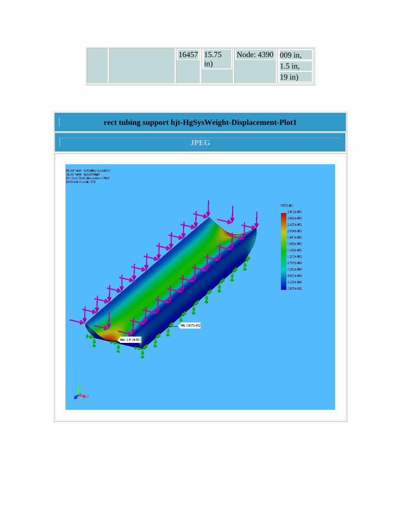
16457 15.75 in)
Node: 4390 009 in, 1.5 in, 19 in)
rect tubing support hjt-HgSysWeight-Displacement-Plot1
JPEG

7. Design Check Results
rect tubing support hjt-HgSysWeight-Design Check-Plot1
JPEG

8. Conclusion Analysis indicates minimum safety factor > 5. Tube considered structurally sound for simulated loading condition.
9. Appendix
Material name: AISI 316 Annealed Stainless Steel Bar (SS)
Description:
Material Source: Library files
Material Library Name: cosmos materials
Material Model Type: Linear Elastic Isotropic
Property Name Value Units Value Type
Elastic modulus 2.7992e+007 psi Constant Poisson's ratio 0.3 NA Constant Mass density 0.28902 lb/in^3 Constant Tensile strength 79771 psi Constant Yield strength 20000 psi Constant Thermal expansion coefficient 8.8889e-006 /Fahrenheit Constant Thermal conductivity 0.00021801 BTU/(in.s.F) Constant Specific heat 0.11945 Btu/(lb.F) Constant Hardening factor (0.0-1.0; 0.0=isotropic; 1.0=kinematic) 0.85 NA Constant

Stress Analysis of Downstream Double Beam Window
Author: V.B. Graves
Company: Oak Ridge National Laboratory
Date: Feb 16, 2006
1. Introduction 2. Materials 3. Load & Restraint Information 4. Study Property 5. Stress Results 6. Displacement Results 7. Design Check Results 8. Conclusion 9. Appendix
1. Introduction A static analysis of the downstream secondary beam window is performed. Loading condition is 1atm internal pressure, which simulates window monitoring conditions. Analysis does not consider any beam-induced stresses.

Note:
Do not base your design decisions solely on the data presented in this report. Use this information in conjunction with experimental data and practical experience. Field testing is mandatory to validate your final design. COSMOSWorks helps you reduce your time-to-market by reducing but not eliminating field tests.
2. Materials
No. Part Name Material Mass Volume 1 double window hjt User Defined 0.491469 lb 3.07168 in^3 2 double window hjt User Defined 0.491469 lb 3.07168 in^3 3 double window hjt User Defined 0.491469 lb 3.07168 in^3 4 double window hjt User Defined 0.491469 lb 3.07168 in^3
3. Load & Restraint Information
Restraint Restraint-1 <double window hjt>
on 1 Face(s) fixed.
Description: Flange fixed.
Restraint-2 <double window hjt>
on 4 Face(s) symmetry
Description:
Load Pressure-1 <double window
on 3 Face(s) with Pressure 15 psi along direction normal to selected face
Sequential Loading
hjt> Description: 15 psi on all internal surfaces.
4. Study Property
Mesh Information Mesh Type: Solid mesh Mesher Used: Standard Automatic Transition: Off Smooth Surface: On Jacobian Check: 4 Points Element Size: 0.11088 in Tolerance: 0.0055439 in Quality: High Number of elements: 19276 Number of nodes: 36992
Solver Information Quality: High Solver Type: FFEPlus Option: Include Thermal Effects Thermal Option: Input Temperature Thermal Option: Reference Temperature at zero strain: 25 Celsius
5. Stress Results

Name Type Min Location Max Location
Plot1 VON: von Mises stress
3.41338 psi Node: 3224
(-2.00785 in, -1.19598 in, 1 in)
18025.4 psi Node: 29934
(-0.994874 in, -1.77189 in, -0.952 in)
double window hjt-Pressure1atm-Stress-Plot1
JPEG

6. Displacement Results
Name Type Min Location Max Location
Plot1 URES: Resultant
0 in Node:
(4.13318e-016 in,
0.032628 in
(0.000173533 in,

displacement 35 -2.25 in, 1 in)
Node: 36345
0 in, -0.976 in)
double window hjt-Pressure1atm-Displacement-Plot1
JPEG

7. Design Check Results
double window hjt-Pressure1atm-Design Check-Plot1
JPEG

8. Conclusion Analysis indicates minimum safety factor > 7 for the window membranes, not considering any beam interactions. For the condition simulated, the structure is considered adequate.
9. Appendix
Material name: User Defined
Description:
Material Source: Input
Material Model Type: Linear Elastic Isotropic
Property Name Value Units Value Type
Elastic modulus 1.52e+007 psi Constant Poisson's ratio 0.31 NA Constant Shear modulus 5.95e+006 psi Constant Mass density 0.16 lb/in^3 Constant Tensile strength 1.2e+005 psi Constant Yield strength 1.28e+005 psi Constant Thermal expansion coefficient 5e-006 /Fahrenheit Constant
Thermal conductivity 8.9611e-005 BTU/(in.s.F) Constant
Specific heat 0.14 Btu/(lb.F) Constant Hardening factor (0.0-1.0; 0.0=isotropic; 1.0=kinematic) 0.85 NA Constant

Stress Analysis of Target Module Support Cradle
Author: V.B. Graves
Company: Oak Ridge National Laboratory
Date: Feb 8, 2006
1. Introduction 2. Materials 3. Load & Restraint Information 4. Study Property 5. Stress Results 6. Displacement Results 7. Design Check Results 8. Conclusion 9. Appendix
1. Introduction A static analysis of the target module support cradle is performed. Target module weight was estimated at 200 lbs for this analysis. An important simplification made was that the turnbuckles which provide vertical support were not included; thus the cradle was analyzed as self-supporting.

Note:
Do not base your design decisions solely on the data presented in this report. Use this information in conjunction with experimental data and practical experience. Field testing is mandatory to validate your final design. COSMOSWorks helps you reduce your time-to-market by reducing but not eliminating field tests.
2. Materials
No. Part Name Material Mass Volume 1 support cradle hjt 6061-T6 (SS) 13.4186 lb 137.565 in^3 2 support cradle hjt 6061-T6 (SS) 13.4186 lb 137.565 in^3 3 support cradle hjt 6061-T6 (SS) 13.4186 lb 137.565 in^3 4 support cradle hjt 6061-T6 (SS) 13.4186 lb 137.565 in^3 5 support cradle hjt 6061-T6 (SS) 13.4186 lb 137.565 in^3 6 support cradle hjt 6061-T6 (SS) 13.4186 lb 137.565 in^3
3. Load & Restraint Information
Restraint Restraint-1 <support cradle hjt>
on 2 Face(s) fixed.
Description: Pads were restrained horizontally and vertically.
Load Force-1 <support on 1 Face(s) apply force 200 lb normal Sequential

cradle hjt> to reference plane with respect to selected reference Edge< 1 > using uniform distribution
Loading
Description: Target module weight simulated as 200 lb vertical load.
4. Study Property
Mesh Information Mesh Type: Solid mesh Mesher Used: Standard Automatic Transition: Off Smooth Surface: On Jacobian Check: 4 Points Element Size: 0.51633 in Tolerance: 0.025816 in Quality: High Number of elements: 15445 Number of nodes: 31017
Solver Information Quality: High Solver Type: FFEPlus Option: Include Thermal Effects Thermal Option: Input Temperature Thermal Option: Reference Temperature at zero strain: 25 Celsius

5. Stress Results
Name Type Min Location Max Location
Plot1 VON: von Mises stress
0.268075 psi Node: 29395
(0.5 in, -1.75 in,10.725 in)
14115.6 psi Node: 17171
(0.719063 in, 1.21296 in, -12.9818 in)
support cradle hjt-TargetWeight-Stress-Plot1
JPEG

6. Displacement Results
Name Type Min Location Max Location
Plot1 URES: Resultant displacement
0 in Node:
(0 in, 2 in,
0.649145 in
(40 in, 17.9149

28395 16.725 in)
Node: 742
in, -3.46455 in)
support cradle hjt-TargetWeight-Displacement-Plot1
JPEG

7. Design Check Results
support cradle hjt-TargetWeight-Design Check-Plot1
JPEG

8. Conclusion Analysis indicates minimum safety factor of 2.8 for this loading condition. Considering that the turnbuckles provide most of the vertical support, this analysis indicates the cradle structure is adequate for this loading condition.
9. Appendix
Material name: 6061-T6 (SS)
Description:
Material Source: Library files
Material Library Name: cosmos materials
Material Model Type: Linear Elastic Isotropic
Property Name Value Units Value Type
Elastic modulus 1.0008e+007 psi Constant Poisson's ratio 0.33 NA Constant Shear modulus 3.771e+006 psi Constant Mass density 0.097544 lb/in^3 Constant Tensile strength 44962 psi Constant Yield strength 39885 psi Constant Thermal expansion coefficient 1.3333e-005 /Fahrenheit Constant Thermal conductivity 0.0022322 BTU/(in.s.F) Constant Specific heat 0.21405 Btu/(lb.F) Constant Hardening factor (0.0-1.0; 0.0=isotropic; 1.0=kinematic) 0.85 NA Constant

E-1
Appendix E. Base Support Structure Documents

MERIT Calculation SheetOak Ridge National Laboratory
Safety FactorFS 73.811=FSSsy
shear:=
Shear stressshear 314.317 psi=shearFA
:=
Weld stress area. Neglect horizontal weld segments.A 2t L⋅:=
Weld lengthL 1.5in:=
Weld throatt 0.707 h⋅:=
Weld leg lengthh 0.375in:=
Distortion energy criteria for shear strengthSsy 0.58Sy:=
Tensile yield strength Al 6061-T6Sy 40000psi:=
Load on each lift pointFW4
:=
Baseplate weightW 1000lbf:=
Lift point welds on the baseplate are checked. Symmetric loading assumed. Baseplate lifted withno other loads!
DATE 12 Apr 2006 CALCULATION BYV. Graves
DRAWING NO 203-HJT-0110 Weld W-1
SHEET 1 OF 1 CALCULATION Baseplate Lift Point Welds
1

MERIT Calculation SheetOak Ridge National Laboratory
Weld length
A 2t L⋅:= Weld stress area
Out-of-plane eccentric loading d 2.25in:= Offset
M F d⋅:= Bending moment
IvL3t12
:= Ix 2 Iv⋅:= Weld segment moment of inertia
normalM L⋅2 Ix⋅
:= normal 1.886 103× psi= Normal stress
shearFA
:= shear 1.572 103× psi= Shear stress
total normal2 shear2+:= total 2.455 103× psi= total stress assumed to act in shear plane
FSSsytotal
:= FS 9.451= Safety Factor
CALCULATION Hydraulic Jack Bracket Welds SHEET 1 OF 1
DRAWING NO 203-HJT-0131 Weld W-1
CALCULATION BYV. Graves DATE 12 Apr 2006
Four jacking brackets are attached to the baseplate. Worst case loading is for the twounder the magnet, with assumed loads of magnet and half the baseplate weight.
Wmag 12000lbf:= Magnet weight
Wbase 1000lbf:= Baseplate weight
FWmag 0.5Wbase+
2:= Load on one bracket
F 6.25 103× lbf=
Sy 40000psi:= Tensile yield strength Al 6061-T6
Ssy 0.58Sy:= Distortion energy criteria for shear strength
h 0.25in:= Weld leg length
t 0.707 h⋅:= Weld throat
L 11.25in:=
1

MERIT Calculation SheetOak Ridge National Laboratory
Safety FactorFS 6.561=FSSsy
shear:=
Shear stressshear 3.536 103× psi=shear
FA
:=
Weld stress areaA 2t L⋅:=
Weld lengthL 5in:=
Weld throatt 0.707 h⋅:=
Only consider fillet weldsWeld leg lengthh 0.25in:=
Distortion energy criteria for shear strength
CALCULATION Hydraulic Jack Bracket Welds SHEET 1 OF 1
DRAWING NO 203-HJT-0131 Weld W-2
CALCULATION BYV. Graves DATE 12 Apr 2006
Four jacking brackets are attached to the baseplate. Worst case loading is for the twounder the magnet, with assumed loads of magnet and half the baseplate weight.
Wmag 12000lbf:= Magnet weight
Wbase 1000lbf:= Baseplate weight
FWmag 0.5Wbase+
2:= Load on one bracket
F 6.25 103× lbf=
Sy 40000psi:= Tensile yield strength Al 6061-T6
Ssy 0.58Sy:=
1
MERIT Calculation SheetOak Ridge National Laboratory
V weld throat
L 11.25in:= Weld length
A 2t L⋅ 2 tvweld⋅ L⋅+:= Weld stress area
Out-of-plane eccentric loading d 2.25in:= Offset
M F d⋅:= Bending moment
IvL3t12
:= Ix 2 Iv⋅:= Weld segment moment of inertia
normalM L⋅2 Ix⋅
:= normal 1.886 103× psi= Normal stress
shearFA
:= shear 523.862 psi= Shear stress
total normal2 shear2+:= total 1.957 103× psi= total stress assumed to act in shear plane
FSSsytotal
:= FS 11.853= Safety Factor
CALCULATION Hydraulic Jack Bracket Welds SHEET 1 OF 1
DRAWING NO 203-HJT-0131 Weld W-1
CALCULATION BYV. Graves DATE 12 Apr 2006
Four jacking brackets are attached to the baseplate. Worst case loading is for the twounder the magnet, with assumed loads of magnet and half the baseplate weight.
Wmag 12000lbf:= Magnet weight
Wbase 1000lbf:= Baseplate weight
FWmag 0.5Wbase+
2:= Load on one bracket
F 6.25 103× lbf=
Sy 40000psi:= Tensile yield strength Al 6061-T6
Ssy 0.58Sy:= Distortion energy criteria for shear strength
h 0.25in:= Fillet weld leg length hvweld .5in:= V weld leg length
t 0.707 h⋅:= Fillet weld throat tvweld 0.707hvweld:=
1

MERIT Calculation SheetOak Ridge National Laboratory
safety 59.895=safety100000psi
stress:=
stress 1.67 103× psi=stress
T 4⋅
π 0.75in( )2⋅:=
SHCS material is SS 18-8 with minimum yield of 100,000 psi. Diameter is 0.75inch, sostress on bolt is
tension force on vertical shcsT 737.604 lbf=TMd
:=
moment on bracketM 1.475 103× lbf in⋅=M F h⋅:=
force on jack boltF 295.042 lbf=F W sin θ( )⋅:=
distance from vertical shcs hole to edge of bracket. used to determineload on tie-down bolt.
d 2in:=
height of horizontal jack bolt hole above baseh 5in:=
tt2 floor slopeθ 4.23deg:=
Conservative assumption of system with HgW 4000lbf:=
The loading condition on the Hg delivery system jacking bracket is calculated. This bracketis located on the common baseplate and the target transporter. Worst case loading occurson the target transporter when the Hg system is being lowered down the sloped TT2 tunnel.
DATE 3 Feb 2006 CALCULATION BYV.B. Graves
DRAWING NO 203-HJT-0120
SHEET 1 OF 1 CALCULATION Hg Cart Bracket Loading
1
Stress Analysis of Cart Restraint Bracket
Author: V.B. Graves
Company: Oak Ridge National Laboratory
Date: May 19, 2006
1. Introduction 2. Materials 3. Load & Restraint Information 4. Study Property 5. Stress Results 6. Displacement Results 7. Design Check Results 8. Conclusion 9. Appendix
1. Introduction A static analysis of the cart jacking bracket is performed. Loading condition simulates Hg delivery system resting against horizontal jack bolt while entire assembly is on the sloped floor of the TT2 tunnel (4.23 deg slope). Horizontal load on hole threads is 4000 * sin(4.23) = 300 lb.

Note:
Do not base your design decisions solely on the data presented in this report. Use this information in conjunction with experimental data and practical experience. Field testing is mandatory to validate your final design. COSMOSWorks helps you reduce your time-to-market by reducing but not eliminating field tests.
2. Materials
No. Part Name Material Mass Volume 1 cart jacking plate hjt 6061-T6 (SS) 2.45111 lb 25.1284 in^3 2 cart jacking plate hjt 6061-T6 (SS) 2.45111 lb 25.1284 in^3 3 cart jacking plate hjt 6061-T6 (SS) 2.45111 lb 25.1284 in^3
3. Load & Restraint Information
Restraint Restraint-1 <cart jacking plate hjt>
on 1 Face(s) fixed.
Description: Vertical hole threads restrained.
Load Force-1 <cart jacking plate hjt>
on 1 Face(s) apply force 300 lb normal to reference plane with respect to selected reference Face< 1 > using uniform distribution
Sequential Loading
Description: Horizontal hole thread loaded by jack bolt.

4. Study Property
Mesh Information Mesh Type: Solid mesh Mesher Used: Standard Automatic Transition: Off Smooth Surface: On Jacobian Check: 4 Points Element Size: 0.29298 in Tolerance: 0.014649 in Quality: High Number of elements: 4993 Number of nodes: 9458
Solver Information Quality: High Solver Type: FFEPlus Option: Include Thermal Effects Thermal Option: Input Temperature Thermal Option: Reference Temperature at zero strain: 25 Celsius
5. Stress Results
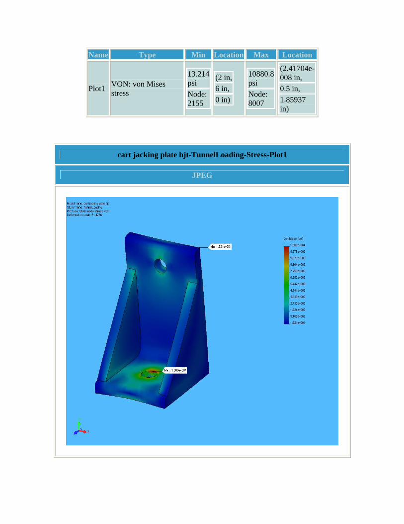
Name Type Min Location Max Location
Plot1 VON: von Mises stress
13.214 psi Node: 2155
(2 in,6 in, 0 in)
10880.8 psi Node: 8007
(2.41704e-008 in, 0.5 in, 1.85937 in)
cart jacking plate hjt-TunnelLoading-Stress-Plot1
JPEG

6. Displacement Results
Name Type Min Location Max Location
Plot1 URES: Resultant displacement
0 in Node: 1657
(0.338291 in, 0.5 in, 2.05469 in)
0.0120834 in Node: 2148
(0 in, 6 in, 0 in)
cart jacking plate hjt-TunnelLoading-Displacement-Plot1
JPEG

7. Design Check Results
cart jacking plate hjt-TunnelLoading-Design Check-Plot1
JPEG

8. Conclusion Maximum stress located near vertical hole, with a corresponding safety factor > 3. Stresses in this region are localized and would relieve as necessary. Bracket considered structurally sound for the simulated loading condition.

9. Appendix
Material name: 6061-T6 (SS)
Description:
Material Source: Library files
Material Library Name: cosmos materials
Material Model Type: Linear Elastic Isotropic
Property Name Value Units Value Type
Elastic modulus 1.0008e+007 psi Constant Poisson's ratio 0.33 NA Constant Shear modulus 3.771e+006 psi Constant Mass density 0.097544 lb/in^3 Constant Tensile strength 44962 psi Constant Yield strength 39885 psi Constant Thermal expansion coefficient 1.3333e-005 /Fahrenheit Constant Thermal conductivity 0.0022322 BTU/(in.s.F) Constant Specific heat 0.21405 Btu/(lb.F) Constant Hardening factor (0.0-1.0; 0.0=isotropic; 1.0=kinematic) 0.85 NA Constant

Stress Analysis of Magnet Support Beam
Author: Author: Van Graves
Company: Oak Ridge National Laboratory
Date: May 11, 2006
1. Introduction 2. Materials 3. Load & Restraint Information 4. Study Property 5. Stress Results 6. Displacement Results 7. Design Check Results 8. Conclusion 9. Appendix
1. Introduction A static analysis of the baseplate support beam is performed. Loading condition simulates in-beam conditions with the beam supporting a percentage of the weights of the magnet (6T), Hg system (2T), and baseplate (800 lbs). Manual calculations show the resultant load on the beam to be 11600 lbs. Loading was evenly distributed on the two circular recesses and applied vertically.
Note:

Do not base your design decisions solely on the data presented in this report. Use this information in conjunction with experimental data and practical experience. Field testing is mandatory to validate your final design. COSMOSWorks helps you reduce your time-to-market by reducing but not eliminating field tests.
2. Materials
No. Part Name Material Mass Volume 1 magnet end support hjt 6061-T6 (SS) 28.4115 lb 291.269 in^3 2 magnet end support hjt 6061-T6 (SS) 28.4115 lb 291.269 in^3 3 magnet end support hjt 6061-T6 (SS) 28.4115 lb 291.269 in^3 4 magnet end support hjt 6061-T6 (SS) 28.4115 lb 291.269 in^3 5 magnet end support hjt 6061-T6 (SS) 28.4115 lb 291.269 in^3 6 magnet end support hjt 6061-T6 (SS) 28.4115 lb 291.269 in^3 7 magnet end support hjt 6061-T6 (SS) 28.4115 lb 291.269 in^3 8 magnet end support hjt 6061-T6 (SS) 28.4115 lb 291.269 in^3 9 magnet end support hjt 6061-T6 (SS) 28.4115 lb 291.269 in^3 10 magnet end support hjt 6061-T6 (SS) 28.4115 lb 291.269 in^3 11 magnet end support hjt 6061-T6 (SS) 28.4115 lb 291.269 in^3 12 magnet end support hjt 6061-T6 (SS) 28.4115 lb 291.269 in^3 13 magnet end support hjt 6061-T6 (SS) 28.4115 lb 291.269 in^3
3. Load & Restraint Information
Restraint Restraint-1 <magnet end support hjt>
on 2 Face(s) fixed.

Description: Bottom faces fixed.
Load Force-1 <magnet end support hjt>
on 2 Face(s) apply normal force 5800 lb using uniform distribution
Sequential Loading
Description: Vertical loading on both recesses.
4. Study Property
Mesh Information Mesh Type: Solid mesh Mesher Used: Standard Automatic Transition: Off Smooth Surface: On Jacobian Check: 4 Points Element Size: 0.66299 in Tolerance: 0.03315 in Quality: High Number of elements: 14905 Number of nodes: 29272
Solver Information Quality: High Solver Type: FFEPlus Option: Include Thermal Effects Thermal Option: Input Temperature Thermal Option: Reference Temperature at zero strain: 77 Fahrenheit

5. Stress Results
Name Type Min Location Max Location
Plot1 VON: von Mises stress
0.314444 psi Node: 9949
(-0.0644952 in, 1.16065 in, -1.52176 in)
3083.53 psi Node: 28859
(1.75 in, 2.23333 in, -22.5625 in)
magnet end support hjt-magnet load-Stress-Plot1
JPEG

6. Displacement Results
Name Type Min Location Max Location
Plot1 URES: Resultant displacement
0 in Node:
(5 in, -3.5 in,
0.00143937 in
(0.333333 in,

22000 24.75 in)
Node: 26759
3.125 in, -22.727 in)
magnet end support hjt-magnet load-Displacement-Plot1
JPEG

7. Design Check Results
magnet end support hjt-magnet load-Design Check-Plot1
JPEG

8. Conclusion Based on maximum calculated stresses, the safety factor is much greater than 3 when compared to material yield strength. The design is considered adequate for the loading condition simulated.
9. Appendix
Material name: 6061-T6 (SS)
Description:
Material Source: Library files
Material Library Name: cosmos materials
Material Model Type: Linear Elastic Isotropic
Property Name Value Units Value Type
Elastic modulus 1.0008e+007 psi Constant Poisson's ratio 0.33 NA Constant Shear modulus 3.771e+006 psi Constant Mass density 0.097544 lb/in^3 Constant Tensile strength 44962 psi Constant Yield strength 39885 psi Constant Thermal expansion coefficient 1.3333e-005 /Fahrenheit Constant Thermal conductivity 0.0022322 BTU/(in.s.F) Constant Specific heat 0.21405 Btu/(lb.F) Constant Hardening factor (0.0-1.0; 0.0=isotropic; 1.0=kinematic) 0.85 NA Constant

Stress Analysis of Common Baseplate - 4 Levelers
Author: Author: Van Graves
Company: Oak Ridge National Laboratory
Date: March 14, 2006
1. Introduction 2. Materials 3. Load & Restraint Information 4. Study Property 5. Stress Results 6. Displacement Results 7. Design Check Results 8. Conclusion 9. Appendix
1. Introduction A static analysis of the common base assembly is performed. The loading condition simulates that encountered when the loaded baseplate (magnet & Hg system) is supported by four leveling jacks. Since the jacking brackets are mechanically attached to the baseplate, the attachment holes were restrained in this analysis. The brackets will be analyzed separately.

Note:
Do not base your design decisions solely on the data presented in this report. Use this information in conjunction with experimental data and practical experience. Field testing is mandatory to validate your final design. COSMOSWorks helps you reduce your time-to-market by reducing but not eliminating field tests.
2. Materials
No. Part Name Material Mass Volume
1 base weldment hjt-1 6061-T6 (SS) 428.213
lb 4389.96 in^3
2 base weldment hjt-1 6061-T6 (SS) 428.213
lb 4389.96 in^3
3 base weldment hjt-1 6061-T6 (SS) 428.213
lb 4389.96 in^3
4 base weldment hjt-1 6061-T6 (SS) 428.213
lb 4389.96 in^3
5 base weldment hjt-1 6061-T6 (SS) 428.213
lb 4389.96 in^3
6 base weldment hjt-1 6061-T6 (SS) 428.213
lb 4389.96 in^3
7 base weldment hjt-1 6061-T6 (SS) 428.213
lb 4389.96 in^3
8 base weldment hjt-1 6061-T6 (SS) 428.213
lb 4389.96 in^3
9 base weldment hjt-1 6061-T6 (SS) 428.213
lb 4389.96 in^3
10 base weldment hjt-1 6061-T6 (SS) 428.213
lb 4389.96 in^3
11 base weldment hjt-1 6061-T6 (SS) 428.213
lb 4389.96 in^3
12 base weldment hjt-1 6061-T6 (SS) 428.213
lb 4389.96 in^3

13 base weldment hjt-1 6061-T6 (SS) 428.213
lb 4389.96 in^3
14 base weldment hjt-1 6061-T6 (SS) 428.213
lb 4389.96 in^3
15 base weldment hjt-1 6061-T6 (SS) 428.213
lb 4389.96 in^3
16 base weldment hjt-1 6061-T6 (SS) 428.213
lb 4389.96 in^3
17 base weldment hjt-1 6061-T6 (SS) 428.213
lb 4389.96 in^3
18 base weldment hjt-1 6061-T6 (SS) 428.213
lb 4389.96 in^3
19 base weldment hjt-1 6061-T6 (SS) 428.213
lb 4389.96 in^3
20 base weldment hjt-1 6061-T6 (SS) 428.213
lb 4389.96 in^3
21 base weldment hjt-1 6061-T6 (SS) 428.213
lb 4389.96 in^3
22 base weldment hjt-1 6061-T6 (SS) 428.213
lb 4389.96 in^3
23 base weldment hjt-1 6061-T6 (SS) 428.213
lb 4389.96 in^3
24 base weldment hjt-1 6061-T6 (SS) 428.213
lb 4389.96 in^3
25 base weldment hjt-1 6061-T6 (SS) 428.213
lb 4389.96 in^3
26 base weldment hjt-1 6061-T6 (SS) 428.213
lb 4389.96 in^3
27 base weldment hjt-1 6061-T6 (SS) 428.213
lb 4389.96 in^3
28 base weldment hjt-1 6061-T6 (SS) 428.213
lb 4389.96 in^3
29 base weldment hjt-1 6061-T6 (SS) 428.213
lb 4389.96 in^3
30 base weldment hjt-1 6061-T6 (SS) 428.213
lb 4389.96 in^3
31 base weldment hjt-1 6061-T6 (SS) 428.213
lb 4389.96 in^3
32 base weldment hjt-1 6061-T6 (SS) 428.213
lb 4389.96 in^3

33 base weldment hjt-1 6061-T6 (SS) 428.213
lb 4389.96 in^3
34 base weldment hjt-1 6061-T6 (SS) 428.213
lb 4389.96 in^3
35 base weldment hjt-1 6061-T6 (SS) 428.213
lb 4389.96 in^3
36 base weldment hjt-1 6061-T6 (SS) 428.213
lb 4389.96 in^3
37 base weldment hjt-1 6061-T6 (SS) 428.213
lb 4389.96 in^3
38 base weldment hjt-1 6061-T6 (SS) 428.213
lb 4389.96 in^3
39 base weldment hjt-1 6061-T6 (SS) 428.213
lb 4389.96 in^3
40 base weldment hjt-1 6061-T6 (SS) 428.213
lb 4389.96 in^3
41 base weldment hjt-1 6061-T6 (SS) 428.213
lb 4389.96 in^3
42 base weldment hjt-1 6061-T6 (SS) 428.213
lb 4389.96 in^3
43 base weldment hjt-1 6061-T6 (SS) 428.213
lb 4389.96 in^3
44 flat rail hjt-1 Wrought Stainless Steel 18.7862 lb 65 in^3
45 flat rail hjt-2 Wrought Stainless Steel 18.7862 lb 65 in^3
46 magnet support plate hjt-1 6061-T6 (SS) 205.676
lb 2108.55 in^3
47 slick sheet hjt-1 Delrin 2700 NC010, Low Viscosity Acetal Copolymer (SS)
2.32213 lb
455.861 in^3
3. Load & Restraint Information
Restraint

Restraint-5 <base weldment hjt-1>
on 8 Face(s) fixed.
Description: Bracket attachment holes restrained.
Load Force-1 <magnet support plate hjt-1>
on 4 Face(s) apply normal force 3000 lb using uniform distribution Sequential
Loading
Description: Magnet weight (6T) distributed on support plate pads.
Force-2 <flat rail hjt-2, flat rail hjt-1>
on 4 Face(s) apply normal force 1000 lb using uniform distribution Sequential
Loading
Description: Hg system weight (2T) distributed on rails at wheel contact locations.
4. Study Property
Mesh Information Mesh Type: Solid mesh Mesher Used: Standard Automatic Transition: Off Smooth Surface: On Jacobian Check: 4 Points Element Size: 1.9207 in Tolerance: 0.096036 in Quality: High Number of elements: 35123 Number of nodes: 63665
Solver Information Quality: High
Solver Type: FFEPlus Option: Include Thermal Effects Thermal Option: Input Temperature Thermal Option: Reference Temperature at zero strain: 77 Fahrenheit
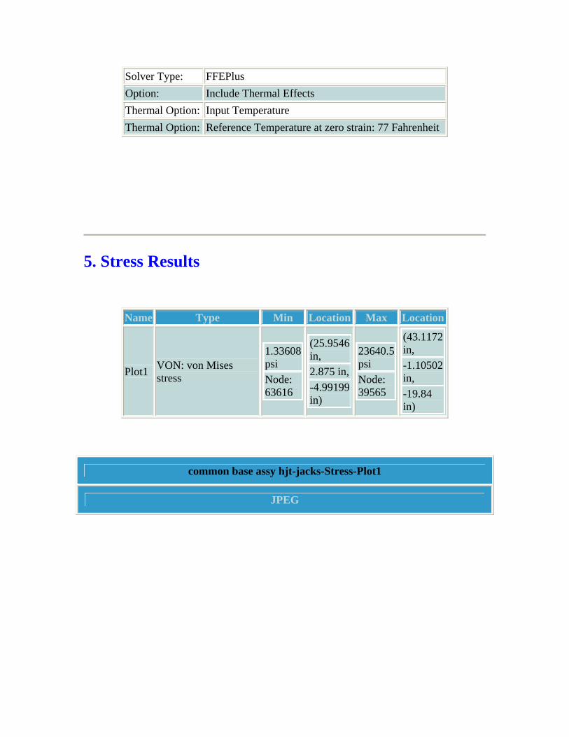
5. Stress Results
Name Type Min Location Max Location
Plot1 VON: von Mises stress
1.33608 psi Node: 63616
(25.9546 in, 2.875 in,-4.99199 in)
23640.5 psi Node: 39565
(43.1172 in, -1.10502 in, -19.84 in)
common base assy hjt-jacks-Stress-Plot1
JPEG

6. Displacement Results
Name Type Min Location Max Location
Plot1 URES: Resultant displacement
0 in Node:
(46.8828 in,
0.0736117 in
(3 in, 3.875
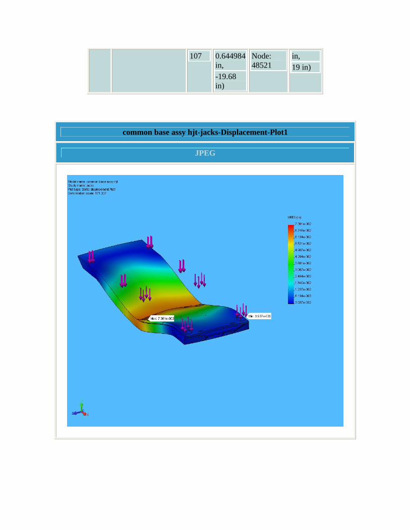
107 0.644984 in, -19.68 in)
Node: 48521
in, 19 in)
common base assy hjt-jacks-Displacement-Plot1
JPEG

7. Design Check Results
common base assy hjt-jacks-Design Check-Plot1
JPEG

common base assy hjt-jacks-Design Check-Plot2
JPEG
common base assy hjt-jacks-Design Check-Plot3
JPEG

common base assy hjt-jacks-Design Check-Plot4
JPEG

common base assy hjt-jacks-Design Check-Plot5
JPEG

8. Conclusion There are some local areas of high stress near the bolt holes in which the calculated safety factor is less than 3. However, these areas are very localized and are not indicative of a high general stress level.

9. Appendix
Material name: 6061-T6 (SS)
Description:
Material Source: Library files
Material Library Name: cosmos materials
Material Model Type: Linear Elastic Isotropic
Property Name Value Units Value Type
Elastic modulus 1.0008e+007 psi Constant Poisson's ratio 0.33 NA Constant Shear modulus 3.771e+006 psi Constant Mass density 0.097544 lb/in^3 Constant Tensile strength 44962 psi Constant Yield strength 39885 psi Constant Thermal expansion coefficient 1.3333e-005 /Fahrenheit Constant Thermal conductivity 0.0022322 BTU/(in.s.F) Constant Specific heat 0.21405 Btu/(lb.F) Constant Hardening factor (0.0-1.0; 0.0=isotropic; 1.0=kinematic) 0.85 NA Constant
Material name: Wrought Stainless Steel
Description:
Material Source: Library files
Material Library Name: cosmos materials
Material Model Type: Linear Elastic Isotropic
Property Name Value Units Value Type Elastic modulus 2.9008e+007 psi Constant

Poisson's ratio 0.26 NA Constant Shear modulus 1.1458e+007 psi Constant Mass density 0.28902 lb/in^3 Constant Tensile strength 74987 psi Constant Yield strength 29995 psi Constant Thermal expansion coefficient 6.1111e-006 /Fahrenheit Constant Thermal conductivity 0.00025412 BTU/(in.s.F) Constant Specific heat 0.11945 Btu/(lb.F) Constant
Material name: Delrin 2700 NC010, Low Viscosity Acetal Copolymer (SS)
Description:
Material Source: Library files
Material Library Name: cosmos materials
Material Model Type: Linear Elastic Isotropic
Property Name Value Units Value Type
Elastic modulus 4.2061e+005 psi Constant Poisson's ratio 0.3 NA Constant Mass density 0.0050939 lb/in^3 Constant Tensile strength 5903 psi Constant Yield strength 9137.4 psi Constant Hardening factor (0.0-1.0; 0.0=isotropic; 1.0=kinematic) 0.85 NA Constant

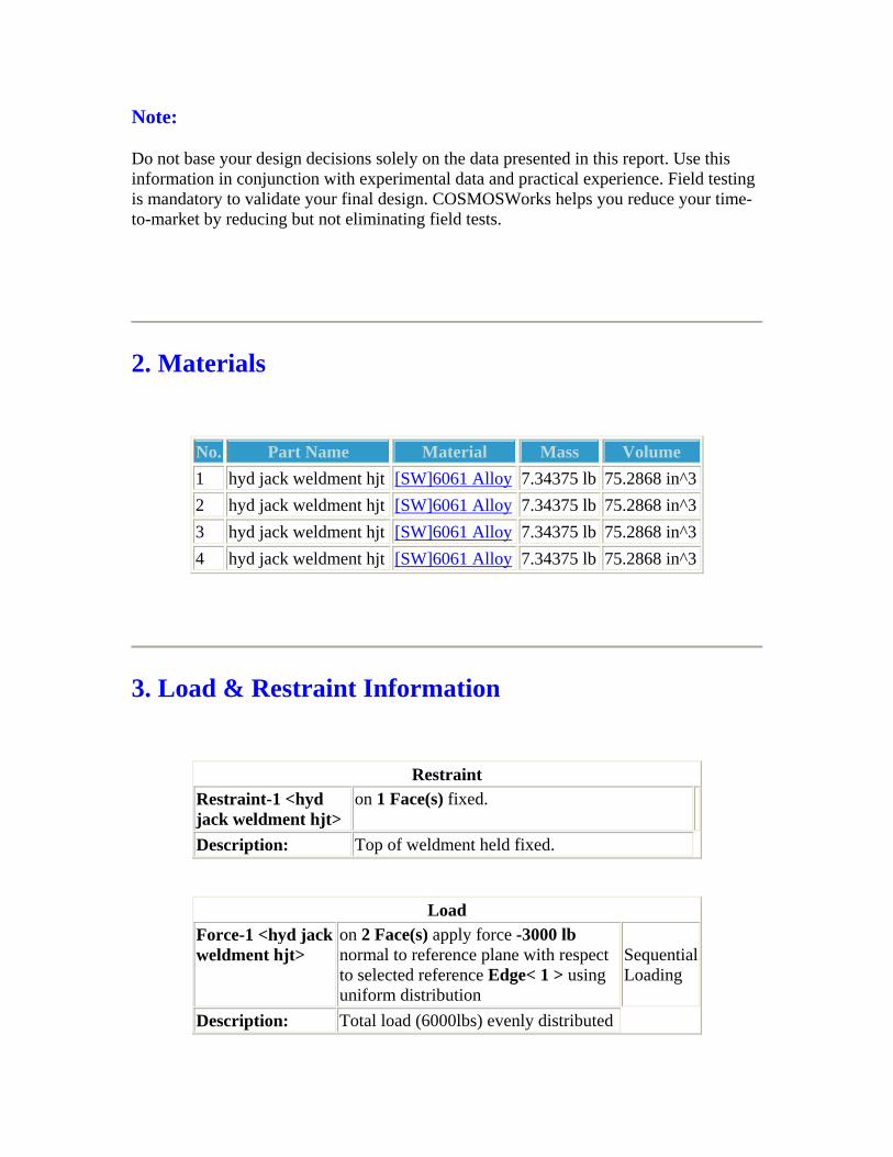
Stress Analysis of Hydraulic Jack Weldment
Author: Author: Van Graves
Company: Oak Ridge National Laboratory
Date: May 5, 2006
1. Introduction 2. Materials 3. Load & Restraint Information 4. Study Property 5. Stress Results 6. Displacement Results 7. Design Check Results 8. Conclusion 9. Appendix
1. Introduction A static analysis of the hydraulic jack weldment is performed. The loading condition simulated mimics the worst case scenario of a loaded baseplate (weight of magnet, Hg system, and baseplate). The load applied was manually calculated based on the distances between the load points and the bracket locations.
Note:
Do not base your design decisions solely on the data presented in this report. Use this information in conjunction with experimental data and practical experience. Field testing is mandatory to validate your final design. COSMOSWorks helps you reduce your time-to-market by reducing but not eliminating field tests.
2. Materials
No. Part Name Material Mass Volume 1 hyd jack weldment hjt [SW]6061 Alloy 7.34375 lb 75.2868 in^3 2 hyd jack weldment hjt [SW]6061 Alloy 7.34375 lb 75.2868 in^3 3 hyd jack weldment hjt [SW]6061 Alloy 7.34375 lb 75.2868 in^3 4 hyd jack weldment hjt [SW]6061 Alloy 7.34375 lb 75.2868 in^3
3. Load & Restraint Information
Restraint Restraint-1 <hyd jack weldment hjt>
on 1 Face(s) fixed.
Description: Top of weldment held fixed.
Load Force-1 <hyd jack weldment hjt>
on 2 Face(s) apply force -3000 lb normal to reference plane with respect to selected reference Edge< 1 > using uniform distribution
Sequential Loading
Description: Total load (6000lbs) evenly distributed

on the two bolt holes.
4. Study Property
Mesh Information Mesh Type: Solid mesh Mesher Used: Standard Automatic Transition: Off Smooth Surface: On Jacobian Check: 4 Points Element Size: 0.42235 in Tolerance: 0.021117 in Quality: High Number of elements: 5513 Number of nodes: 11121
Solver Information Quality: High Solver Type: FFEPlus Option: Include Thermal Effects Thermal Option: Input Temperature Thermal Option: Reference Temperature at zero strain: 77 Fahrenheit
5. Stress Results

Name Type Min Location Max Location
Plot1 VON: von Mises stress
0.0528316 psi Node: 6003
(-3 in, -0.125 in, 5.5 in)
5639.15 psi Node: 2377
(2.05831 in, -10.0128 in, 0 in)
hyd jack weldment hjt-loaded-Stress-Plot1
JPEG

6. Displacement Results
Name Type Min Location Max Location
Plot1 URES: Resultant displacement
0 in Node: 19
(-2.5 in,-0.5 in, 0.5 in)
0.00541518 in Node: 2145
(2 in, -11.25 in, 0 in)
hyd jack weldment hjt-loaded-Displacement-Plot1
JPEG

7. Design Check Results
hyd jack weldment hjt-loaded-Design Check-Plot1
JPEG

8. Conclusion The analysis indicates localized high stresses near the bolt holes, but no stresses are above yield strength of the material. Any local deformation will relieve the stresses, so the structure is considered adequate for the simulated loading condition.

9. Appendix
Material name: [SW]6061 Alloy
Description:
Material Source: Used SolidWorks material
Material Library Name:
Material Model Type: Linear Elastic Isotropic
Property Name Value Units Value Type Elastic modulus 1.0008e+007 psi Constant Poisson's ratio 0.33 NA Constant Shear modulus 3.771e+006 psi Constant Mass density 0.097544 lb/in^3 Constant Tensile strength 17997 psi Constant Yield strength 7998.6 psi Constant Thermal expansion coefficient 1.3333e-005 /Fahrenheit Constant Thermal conductivity 0.0022737 BTU/(in.s.F) Constant Specific heat 0.31056 Btu/(lb.F) Constant

Stress Analysis of Common Baseplate - 4 Levelers
Author: Author: Van Graves
Company: Oak Ridge National Laboratory
Date: March 14, 2006
1. Introduction 2. Materials 3. Load & Restraint Information 4. Study Property 5. Stress Results 6. Displacement Results 7. Design Check Results 8. Conclusion 9. Appendix
1. Introduction A static analysis of the common base assembly is performed. The loading condition simulates that encountered when the loaded baseplate (magnet & Hg system) is supported by four leveling jacks.
Note:
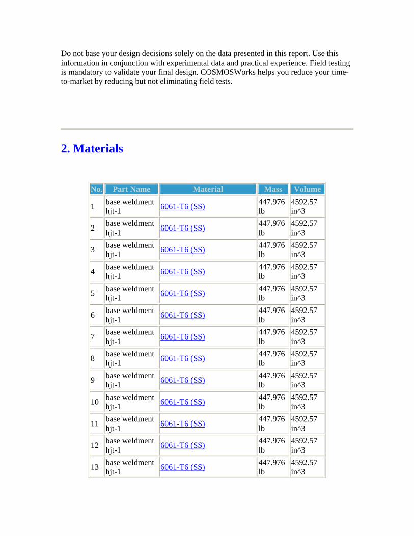
Do not base your design decisions solely on the data presented in this report. Use this information in conjunction with experimental data and practical experience. Field testing is mandatory to validate your final design. COSMOSWorks helps you reduce your time-to-market by reducing but not eliminating field tests.
2. Materials
No. Part Name Material Mass Volume
1 base weldment hjt-1 6061-T6 (SS) 447.976
lb 4592.57 in^3
2 base weldment hjt-1 6061-T6 (SS) 447.976
lb 4592.57 in^3
3 base weldment hjt-1 6061-T6 (SS) 447.976
lb 4592.57 in^3
4 base weldment hjt-1 6061-T6 (SS) 447.976
lb 4592.57 in^3
5 base weldment hjt-1 6061-T6 (SS) 447.976
lb 4592.57 in^3
6 base weldment hjt-1 6061-T6 (SS) 447.976
lb 4592.57 in^3
7 base weldment hjt-1 6061-T6 (SS) 447.976
lb 4592.57 in^3
8 base weldment hjt-1 6061-T6 (SS) 447.976
lb 4592.57 in^3
9 base weldment hjt-1 6061-T6 (SS) 447.976
lb 4592.57 in^3
10 base weldment hjt-1 6061-T6 (SS) 447.976
lb 4592.57 in^3
11 base weldment hjt-1 6061-T6 (SS) 447.976
lb 4592.57 in^3
12 base weldment hjt-1 6061-T6 (SS) 447.976
lb 4592.57 in^3
13 base weldment hjt-1 6061-T6 (SS) 447.976
lb 4592.57 in^3

14 base weldment hjt-1 6061-T6 (SS) 447.976
lb 4592.57 in^3
15 base weldment hjt-1 6061-T6 (SS) 447.976
lb 4592.57 in^3
16 base weldment hjt-1 6061-T6 (SS) 447.976
lb 4592.57 in^3
17 base weldment hjt-1 6061-T6 (SS) 447.976
lb 4592.57 in^3
18 base weldment hjt-1 6061-T6 (SS) 447.976
lb 4592.57 in^3
19 base weldment hjt-1 6061-T6 (SS) 447.976
lb 4592.57 in^3
20 base weldment hjt-1 6061-T6 (SS) 447.976
lb 4592.57 in^3
21 base weldment hjt-1 6061-T6 (SS) 447.976
lb 4592.57 in^3
22 base weldment hjt-1 6061-T6 (SS) 447.976
lb 4592.57 in^3
23 base weldment hjt-1 6061-T6 (SS) 447.976
lb 4592.57 in^3
24 base weldment hjt-1 6061-T6 (SS) 447.976
lb 4592.57 in^3
25 base weldment hjt-1 6061-T6 (SS) 447.976
lb 4592.57 in^3
26 base weldment hjt-1 6061-T6 (SS) 447.976
lb 4592.57 in^3
27 base weldment hjt-1 6061-T6 (SS) 447.976
lb 4592.57 in^3
28 base weldment hjt-1 6061-T6 (SS) 447.976
lb 4592.57 in^3
29 base weldment hjt-1 6061-T6 (SS) 447.976
lb 4592.57 in^3
30 base weldment hjt-1 6061-T6 (SS) 447.976
lb 4592.57 in^3
31 base weldment hjt-1 6061-T6 (SS) 447.976
lb 4592.57 in^3
32 base weldment hjt-1 6061-T6 (SS) 447.976
lb 4592.57 in^3
33 base weldment hjt-1 6061-T6 (SS) 447.976
lb 4592.57 in^3

34 base weldment hjt-1 6061-T6 (SS) 447.976
lb 4592.57 in^3
35 base weldment hjt-1 6061-T6 (SS) 447.976
lb 4592.57 in^3
36 base weldment hjt-1 6061-T6 (SS) 447.976
lb 4592.57 in^3
37 base weldment hjt-1 6061-T6 (SS) 447.976
lb 4592.57 in^3
38 base weldment hjt-1 6061-T6 (SS) 447.976
lb 4592.57 in^3
39 base weldment hjt-1 6061-T6 (SS) 447.976
lb 4592.57 in^3
40 base weldment hjt-1 6061-T6 (SS) 447.976
lb 4592.57 in^3
41 base weldment hjt-1 6061-T6 (SS) 447.976
lb 4592.57 in^3
42 base weldment hjt-1 6061-T6 (SS) 447.976
lb 4592.57 in^3
43 base weldment hjt-1 6061-T6 (SS) 447.976
lb 4592.57 in^3
44 flat rail hjt-1 Wrought Stainless Steel 18.7862 lb 65 in^3
45 flat rail hjt-2 Wrought Stainless Steel 18.7862 lb 65 in^3
46 magnet support plate hjt-1 6061-T6 (SS) 205.676
lb 2108.55 in^3
47 slick sheet hjt-1 Delrin 2700 NC010, Low Viscosity Acetal Copolymer (SS)
2.32213 lb
455.861 in^3
3. Load & Restraint Information
Restraint Restraint-3 <base weldment hjt-1>
on 4 Face(s) fixed.

Description: Threaded holes for leveling jacks are fixed.
Load Force-1 <magnet support plate hjt-1>
on 4 Face(s) apply normal force 3000 lb using uniform distribution Sequential
Loading
Description: Magnet weight (6T) distributed on support plate pads.
Force-2 <flat rail hjt-2, flat rail hjt-1>
on 4 Face(s) apply normal force 1000 lb using uniform distribution Sequential
Loading
Description: Hg system weight (2T) distributed on rails at wheel contact locations.
4. Study Property
Mesh Information Mesh Type: Solid mesh Mesher Used: Standard Automatic Transition: Off Smooth Surface: On Jacobian Check: 4 Points Element Size: 1.6804 in Tolerance: 0.08402 in Quality: High Number of elements: 45106 Number of nodes: 81757
Solver Information Quality: High Solver Type: FFEPlus Option: Include Thermal Effects

Thermal Option: Input Temperature Thermal Option: Reference Temperature at zero strain: 77 Fahrenheit
5. Stress Results
Name Type Min Location Max Location
Plot1 VON: von Mises stress
1.59852 psi Node: 58699
(-59.2137 in, 0.302294 in, -2.5138 in)
17874.7 psi Node: 35675
(36.3789 in, -1.25 in, 22.0312 in)
common base assy hjt-levelers-Stress-Plot1
JPEG

6. Displacement Results
Name Type Min Location Max Location
Plot1 URES: Resultant displacement
0 in Node:
(36.3789 in,
0.0434563 in
(63 in, 2.625

35637 -0.5 in, 22.0312 in)
Node: 2545
in, 9.25 in)
common base assy hjt-levelers-Displacement-Plot1
JPEG

7. Design Check Results
common base assy hjt-levelers-Design Check-Plot12
JPEG
common base assy hjt-levelers-Design Check-Plot17

JPEG
common base assy hjt-levelers-Design Check-Plot18
JPEG

common base assy hjt-levelers-Design Check-Plot4
JPEG

common base assy hjt-levelers-Design Check-Plot5
JPEG

8. Conclusion Analysis indicates minimum safety factor (2.2) near edge of leveling jack holes under magnet. These are localized stresses and are not indicative of a general stress level. Local deformation will relieve these stresses, so the baseplate design is considered structurally

adequate for the simulated loading condition.
9. Appendix
Material name: 6061-T6 (SS)
Description:
Material Source: Library files
Material Library Name: cosmos materials
Material Model Type: Linear Elastic Isotropic
Property Name Value Units Value Type
Elastic modulus 1.0008e+007 psi Constant Poisson's ratio 0.33 NA Constant Shear modulus 3.771e+006 psi Constant Mass density 0.097544 lb/in^3 Constant Tensile strength 44962 psi Constant Yield strength 39885 psi Constant Thermal expansion coefficient 1.3333e-005 /Fahrenheit Constant Thermal conductivity 0.0022322 BTU/(in.s.F) Constant Specific heat 0.21405 Btu/(lb.F) Constant Hardening factor (0.0-1.0; 0.0=isotropic; 1.0=kinematic) 0.85 NA Constant
Material name: Wrought Stainless Steel
Description:
Material Source: Library files
Material Library Name: cosmos materials
Material Model Type: Linear Elastic Isotropic
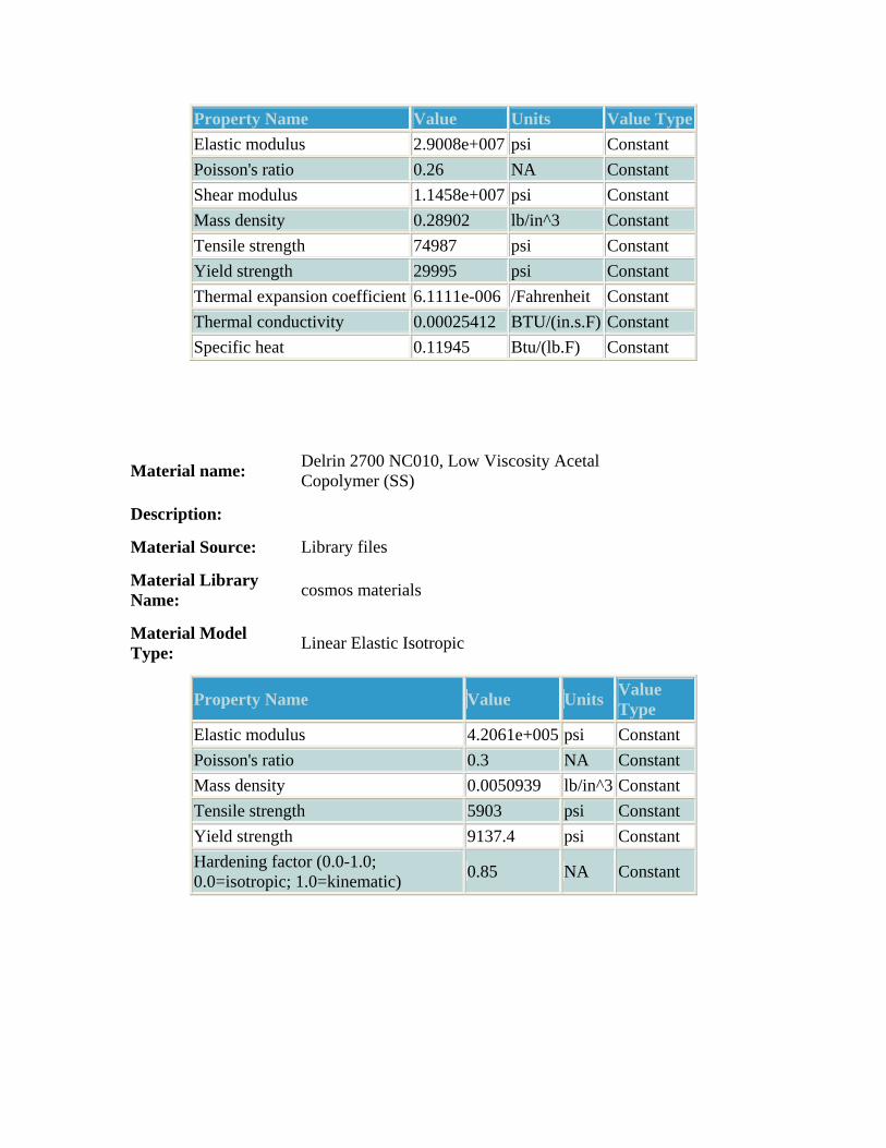
Property Name Value Units Value Type Elastic modulus 2.9008e+007 psi Constant Poisson's ratio 0.26 NA Constant Shear modulus 1.1458e+007 psi Constant Mass density 0.28902 lb/in^3 Constant Tensile strength 74987 psi Constant Yield strength 29995 psi Constant Thermal expansion coefficient 6.1111e-006 /Fahrenheit Constant Thermal conductivity 0.00025412 BTU/(in.s.F) Constant Specific heat 0.11945 Btu/(lb.F) Constant
Material name: Delrin 2700 NC010, Low Viscosity Acetal Copolymer (SS)
Description:
Material Source: Library files
Material Library Name: cosmos materials
Material Model Type: Linear Elastic Isotropic
Property Name Value Units Value Type
Elastic modulus 4.2061e+005 psi Constant Poisson's ratio 0.3 NA Constant Mass density 0.0050939 lb/in^3 Constant Tensile strength 5903 psi Constant Yield strength 9137.4 psi Constant Hardening factor (0.0-1.0; 0.0=isotropic; 1.0=kinematic) 0.85 NA Constant

Stress Analysis of Common Baseplate - 3 Rollers
Author: Author: Van Graves
Company: Oak Ridge National Laboratory
Date: April 23, 2006
1. Introduction 2. Materials 3. Load & Restraint Information 4. Study Property 5. Stress Results 6. Displacement Results 7. Design Check Results 8. Conclusion 9. Appendix
1. Introduction A static analysis of the common base assembly is performed. The loading condition simulates one encountered when the loaded baseplate (with magnet & Hg system) is supported by three Hilman rollers. This situation will occur during system alignment with the beamline.

Note:
Do not base your design decisions solely on the data presented in this report. Use this information in conjunction with experimental data and practical experience. Field testing is mandatory to validate your final design. COSMOSWorks helps you reduce your time-to-market by reducing but not eliminating field tests.
2. Materials
No. Part Name Material Mass Volume
1 base weldment hjt-1 6061-T6 (SS) 428.213
lb 4389.96 in^3
2 base weldment hjt-1 6061-T6 (SS) 428.213
lb 4389.96 in^3
3 base weldment hjt-1 6061-T6 (SS) 428.213
lb 4389.96 in^3
4 base weldment hjt-1 6061-T6 (SS) 428.213
lb 4389.96 in^3
5 base weldment hjt-1 6061-T6 (SS) 428.213
lb 4389.96 in^3
6 base weldment hjt-1 6061-T6 (SS) 428.213
lb 4389.96 in^3
7 base weldment hjt-1 6061-T6 (SS) 428.213
lb 4389.96 in^3
8 base weldment hjt-1 6061-T6 (SS) 428.213
lb 4389.96 in^3
9 base weldment hjt-1 6061-T6 (SS) 428.213
lb 4389.96 in^3
10 base weldment hjt-1 6061-T6 (SS) 428.213
lb 4389.96 in^3
11 base weldment hjt-1 6061-T6 (SS) 428.213
lb 4389.96 in^3
12 base weldment hjt-1 6061-T6 (SS) 428.213
lb 4389.96 in^3

13 base weldment hjt-1 6061-T6 (SS) 428.213
lb 4389.96 in^3
14 base weldment hjt-1 6061-T6 (SS) 428.213
lb 4389.96 in^3
15 base weldment hjt-1 6061-T6 (SS) 428.213
lb 4389.96 in^3
16 base weldment hjt-1 6061-T6 (SS) 428.213
lb 4389.96 in^3
17 base weldment hjt-1 6061-T6 (SS) 428.213
lb 4389.96 in^3
18 base weldment hjt-1 6061-T6 (SS) 428.213
lb 4389.96 in^3
19 base weldment hjt-1 6061-T6 (SS) 428.213
lb 4389.96 in^3
20 base weldment hjt-1 6061-T6 (SS) 428.213
lb 4389.96 in^3
21 base weldment hjt-1 6061-T6 (SS) 428.213
lb 4389.96 in^3
22 base weldment hjt-1 6061-T6 (SS) 428.213
lb 4389.96 in^3
23 base weldment hjt-1 6061-T6 (SS) 428.213
lb 4389.96 in^3
24 base weldment hjt-1 6061-T6 (SS) 428.213
lb 4389.96 in^3
25 base weldment hjt-1 6061-T6 (SS) 428.213
lb 4389.96 in^3
26 base weldment hjt-1 6061-T6 (SS) 428.213
lb 4389.96 in^3
27 base weldment hjt-1 6061-T6 (SS) 428.213
lb 4389.96 in^3
28 base weldment hjt-1 6061-T6 (SS) 428.213
lb 4389.96 in^3
29 base weldment hjt-1 6061-T6 (SS) 428.213
lb 4389.96 in^3
30 base weldment hjt-1 6061-T6 (SS) 428.213
lb 4389.96 in^3
31 base weldment hjt-1 6061-T6 (SS) 428.213
lb 4389.96 in^3
32 base weldment hjt-1 6061-T6 (SS) 428.213
lb 4389.96 in^3

33 base weldment hjt-1 6061-T6 (SS) 428.213
lb 4389.96 in^3
34 base weldment hjt-1 6061-T6 (SS) 428.213
lb 4389.96 in^3
35 base weldment hjt-1 6061-T6 (SS) 428.213
lb 4389.96 in^3
36 base weldment hjt-1 6061-T6 (SS) 428.213
lb 4389.96 in^3
37 base weldment hjt-1 6061-T6 (SS) 428.213
lb 4389.96 in^3
38 base weldment hjt-1 6061-T6 (SS) 428.213
lb 4389.96 in^3
39 base weldment hjt-1 6061-T6 (SS) 428.213
lb 4389.96 in^3
40 base weldment hjt-1 6061-T6 (SS) 428.213
lb 4389.96 in^3
41 base weldment hjt-1 6061-T6 (SS) 428.213
lb 4389.96 in^3
42 base weldment hjt-1 6061-T6 (SS) 428.213
lb 4389.96 in^3
43 base weldment hjt-1 6061-T6 (SS) 428.213
lb 4389.96 in^3
44 flat rail hjt-1 Wrought Stainless Steel 18.7862 lb 65 in^3
45 flat rail hjt-2 Wrought Stainless Steel 18.7862 lb 65 in^3
46 magnet support plate hjt-1 6061-T6 (SS) 205.676
lb 2108.55 in^3
47 slick sheet hjt-1 Delrin 2700 NC010, Low Viscosity Acetal Copolymer (SS)
2.32213 lb
455.861 in^3
3. Load & Restraint Information
Restraint

Restraint-1 <base weldment hjt-1>
on 3 Face(s) fixed.
Description: Roller pads fixed
Load Force-1 <magnet support plate hjt-1>
on 4 Face(s) apply normal force 3000 lb using uniform distribution Sequential
Loading
Description: Magnet weight evenly distributed on pads
Force-2 <flat rail hjt-1, flat rail hjt-2>
on 4 Face(s) apply normal force 1000 lb using uniform distribution Sequential
Loading
Description: Hg system weight evenly distributed on sections of rail
4. Study Property
Mesh Information Mesh Type: Solid mesh Mesher Used: Standard Automatic Transition: Off Smooth Surface: On Jacobian Check: 4 Points Element Size: 1.5846 in Tolerance: 0.07923 in Quality: High Number of elements: 46335 Number of nodes: 83724
Solver Information Quality: High

Solver Type: FFEPlus Option: Include Thermal Effects Thermal Option: Input Temperature Thermal Option: Reference Temperature at zero strain: 77 Fahrenheit
5. Stress Results
Name Type Min Location Max Location
Plot1 VON: von Mises stress
3.78184 psi Node: 80530
(52.6774 in, 2.75 in, -9.22699e-007 in)
31114.5 psi Node: 36807
(-49 in, -1.33534 in, 0.098234 in)
common base assy hjt-rollers-Stress-Plot1
JPEG

6. Displacement Results
Name Type Min Location Max Location
Plot1 URES: Resultant displacement
0 in Node:
(54 in, -1.9 in,
0.14714 in
(3 in, 3.875

27840 -19.5 in)
Node: 64726
in, 19 in)
common base assy hjt-rollers-Displacement-Plot1
JPEG

7. Design Check Results
common base assy hjt-rollers-Design Check-Plot4
JPEG
common base assy hjt-rollers-Design Check-Plot7

JPEG
common base assy hjt-rollers-Design Check-Plot9
JPEG

common base assy hjt-rollers-Design Check-Plot6
JPEG

common base assy hjt-rollers-Design Check-Plot8
JPEG

common base assy hjt-rollers-Design Check-Plot10
JPEG
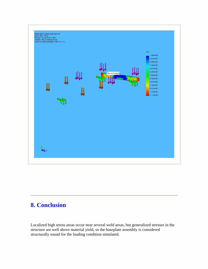
8. Conclusion Localized high stress areas occur near several weld areas, but generalized stresses in the structure are well above material yield, so the baseplate assembly is considered structurally sound for the loading condition simulated.

9. Appendix
Material name: 6061-T6 (SS)
Description:
Material Source: Library files
Material Library Name: cosmos materials
Material Model Type: Linear Elastic Isotropic
Property Name Value Units Value Type
Elastic modulus 1.0008e+007 psi Constant Poisson's ratio 0.33 NA Constant Shear modulus 3.771e+006 psi Constant Mass density 0.097544 lb/in^3 Constant Tensile strength 44962 psi Constant Yield strength 39885 psi Constant Thermal expansion coefficient 1.3333e-005 /Fahrenheit Constant Thermal conductivity 0.0022322 BTU/(in.s.F) Constant Specific heat 0.21405 Btu/(lb.F) Constant Hardening factor (0.0-1.0; 0.0=isotropic; 1.0=kinematic) 0.85 NA Constant
Material name: Wrought Stainless Steel
Description:
Material Source: Library files
Material Library Name: cosmos materials
Material Model Type: Linear Elastic Isotropic
Property Name Value Units Value Type Elastic modulus 2.9008e+007 psi Constant

Poisson's ratio 0.26 NA Constant Shear modulus 1.1458e+007 psi Constant Mass density 0.28902 lb/in^3 Constant Tensile strength 74987 psi Constant Yield strength 29995 psi Constant Thermal expansion coefficient 6.1111e-006 /Fahrenheit Constant Thermal conductivity 0.00025412 BTU/(in.s.F) Constant Specific heat 0.11945 Btu/(lb.F) Constant
Material name: Delrin 2700 NC010, Low Viscosity Acetal Copolymer (SS)
Description:
Material Source: Library files
Material Library Name: cosmos materials
Material Model Type: Linear Elastic Isotropic
Property Name Value Units Value Type
Elastic modulus 4.2061e+005 psi Constant Poisson's ratio 0.3 NA Constant Mass density 0.0050939 lb/in^3 Constant Tensile strength 5903 psi Constant Yield strength 9137.4 psi Constant Hardening factor (0.0-1.0; 0.0=isotropic; 1.0=kinematic) 0.85 NA Constant

Stress Analysis of Hg System Cart
Author: V.B. Graves
Company: Oak Ridge National Laboratory
Date: May 19, 2006
1. Introduction 2. Materials 3. Load & Restraint Information 4. Study Property 5. Stress Results 6. Displacement Results 7. Design Check Results 8. Conclusion 9. Appendix
1. Introduction A static analysis of the Hg system transport cart is performed. Simulated load of 4000 lbs was evenly distributed on two strips across the top surface of the cart. Actual assembly includes UMHW sheet and another Aluminum plate, with the loading occurring on the top plate. Simulated condition should provide conservative results since upper plate will further distribute load on lower plate. Other simplifying assumption was the removal of the cart wheel, so the axle holes were restrained.

Note:
Do not base your design decisions solely on the data presented in this report. Use this information in conjunction with experimental data and practical experience. Field testing is mandatory to validate your final design. COSMOSWorks helps you reduce your time-to-market by reducing but not eliminating field tests.
2. Materials
No. Part Name Material Mass Volume 1 cart lower plate hjt 6061-T6 (SS) 104.029 lb 1066.49 in^3 2 cart lower plate hjt 6061-T6 (SS) 104.029 lb 1066.49 in^3 3 cart lower plate hjt 6061-T6 (SS) 104.029 lb 1066.49 in^3 4 cart lower plate hjt 6061-T6 (SS) 104.029 lb 1066.49 in^3 5 cart lower plate hjt 6061-T6 (SS) 104.029 lb 1066.49 in^3 6 cart lower plate hjt 6061-T6 (SS) 104.029 lb 1066.49 in^3 7 cart lower plate hjt 6061-T6 (SS) 104.029 lb 1066.49 in^3 8 cart lower plate hjt 6061-T6 (SS) 104.029 lb 1066.49 in^3 9 cart lower plate hjt 6061-T6 (SS) 104.029 lb 1066.49 in^3
3. Load & Restraint Information
Restraint Restraint-1 <cart lower plate hjt>
on 4 Face(s) fixed.
Description: Axles holes fixed.

Load Force-1 <cart lower plate hjt>
on 2 Face(s) apply normal force 2000 lb using uniform distribution
Sequential Loading
Description: 2000 lbs on each load strip.
4. Study Property
Mesh Information Mesh Type: Solid mesh Mesher Used: Standard Automatic Transition: Off Smooth Surface: On Jacobian Check: 4 Points Element Size: 1.0218 in Tolerance: 0.051091 in Quality: High Number of elements: 9988 Number of nodes: 20458
Solver Information Quality: High Solver Type: FFEPlus Option: Include Thermal Effects Thermal Option: Input Temperature Thermal Option: Reference Temperature at zero strain: 25 Celsius

5. Stress Results
Name Type Min Location Max Location
Plot1 VON: von Mises stress
7.27537 psi Node: 13063
(18.3384 in, 0 in, -1.0218 in)
10015 psi Node: 19332
(-15.1511 in, -0.767816 in, -15.5 in)
cart lower plate hjt-HgSysWeight-Stress-Plot1
JPEG

6. Displacement Results
Name Type Min Location Max Location
Plot1 URES: Resultant displacement
0 in Node:
(18.5 in,-5.6325
0.0615473 in
(-5.07733 in,

18426 in, -15.5 in)
Node: 11466
0 in, -0.00920064 in)
cart lower plate hjt-HgSysWeight-Displacement-Plot1
JPEG

7. Design Check Results
cart lower plate hjt-HgSysWeight-Design Check-Plot1
JPEG

8. Conclusion Analysis shows minimum safety factor = 4, with maximum stress occuring in localized area near welded joint. Structure is considered structurally sound for loading condition simulated.
9. Appendix
Material name: 6061-T6 (SS)
Description:
Material Source: Library files
Material Library Name: cosmos materials
Material Model Type: Linear Elastic Isotropic
Property Name Value Units Value Type
Elastic modulus 1.0008e+007 psi Constant Poisson's ratio 0.33 NA Constant Shear modulus 3.771e+006 psi Constant Mass density 0.097544 lb/in^3 Constant Tensile strength 44962 psi Constant Yield strength 39885 psi Constant Thermal expansion coefficient 1.3333e-005 /Fahrenheit Constant Thermal conductivity 0.0022322 BTU/(in.s.F) Constant Specific heat 0.21405 Btu/(lb.F) Constant Hardening factor (0.0-1.0; 0.0=isotropic; 1.0=kinematic) 0.85 NA Constant

F-1
Appendix F. Jerome® Vapor Monitor
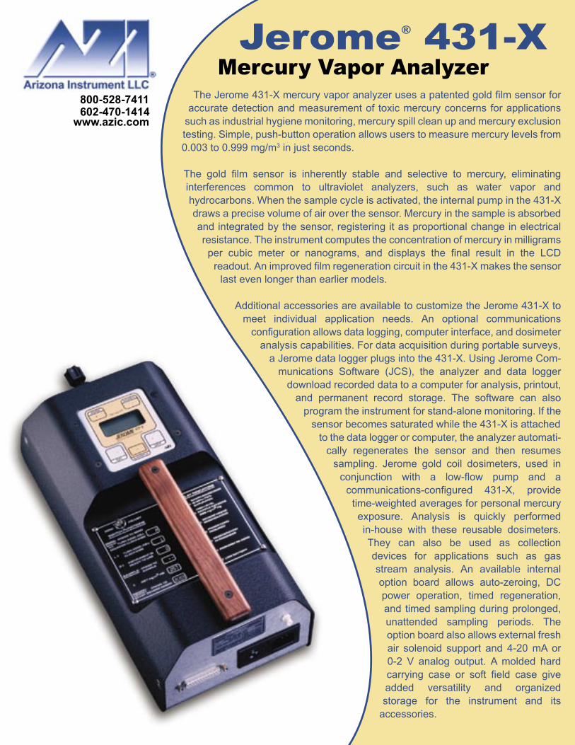
The Jerome 431-X mercury vapor analyzer uses a patented gold film sensor for accurate detection and measurement of toxic mercury concerns for applications
such as industrial hygiene monitoring, mercury spill clean up and mercury exclusion testing. Simple, push-button operation allows users to measure mercury levels from0.003 to 0.999 mg/m3 in just seconds.
The gold film sensor is inherently stable and selective to mercury, eliminating interferences common to ultraviolet analyzers, such as water vapor and hydrocarbons. When the sample cycle is activated, the internal pump in the 431-X draws a precise volume of air over the sensor. Mercury in the sample is absorbed and integrated by the sensor, registering it as proportional change in electrical resistance. The instrument computes the concentration of mercury in milligrams per cubic meter or nanograms, and displays the final result in the LCD
readout. An improved film regeneration circuit in the 431-X makes the sensorlast even longer than earlier models.
Additional accessories are available to customize the Jerome 431-X to meet individual application needs. An optional communications
configuration allows data logging, computer interface, and dosimeter analysis capabilities. For data acquisition during portable surveys,
a Jerome data logger plugs into the 431-X. Using Jerome Com-munications Software (JCS), the analyzer and data logger
download recorded data to a computer for analysis, printout, and permanent record storage. The software can also
program the instrument for stand-alone monitoring. If the sensor becomes saturated while the 431-X is attached
to the data logger or computer, the analyzer automati-cally regenerates the sensor and then resumes
sampling. Jerome gold coil dosimeters, used in conjunction with a low-flow pump and a
communications-configured 431-X, provide time-weighted averages for personal mercury exposure. Analysis is quickly performed in-house with these reusable dosimeters. They can also be used as collection devices for applications such as gas stream analysis. An available internal option board allows auto-zeroing, DC power operation, timed regeneration, and timed sampling during prolonged, unattended sampling periods. The option board also allows external fresh air solenoid support and 4-20 mA or 0-2 V analog output. A molded hard carrying case or soft field case give added versatility and organized storage for the instrument and its
accessories.
Jerome® 431-XMercury Vapor Analyzer

Features:Rugged and easy operateInherently stable gold film sensorPressure sensitive membrane switch operationAccurate analysis of mercury vapor in secondsRechargeable internal battery pack for portabilityWide detection range allows for multiple applicationsAutomatic LCD backlight during low light conditionsSurvey mode for rapid source detection of mercury vapor concentrationsMicroprocessor ensures a linear response throughout the entire range of the sensor
Specifications:Resolution 0.001 mg/m3
Detection Range 0.003-0.999 mg/m3
Precision 5% Relative Standard Deviation at 0.100 mg/m3
Accuracy ±5% at 0.100 mg/m3
Response Time 13 seconds in Sample Mode; 4 seconds in Survey ModeFlow Rate 750 cc/minEnvironmental Range 0-40°C, noncondensing, nonexplosiveInterface RS-232 port using Jerome Communications SoftwareDimensions 431-X: 6” W x 13” L x 4” H/ 16 cm W x 33 cm L x 10 cm H 431-XE: 7” W x 14” L x 7” H / 18 cm W x 35 cm L x 18 cm HWeight 431-X: 7 lbs / 3 kg 431-XE: 8 lbs / 3.5 kgInternal Battery Pack Rechargeable nickel-cadmiumPower Requirements 100-120 V~, 50/60 Hz, 1 A or 220-240 V~, 50/60 Hz, 1 AWarranty 1 year, factory parts and laborMarks European Communities (CE) for 220-240 V~ 431-XE model only
Options:Data Logger to record field monitoring informationMaintenance Kit for routine maintenance and upkeepFunctional Test Kit for sensor operation verification in the fieldHard or Soft Field Carrying Case for versatile handling and additional storageJerome Communications Software Kit for downloading information from the data logger to a PC or for unattended, fixed-point samplingDosimeters to provide time-weighted averages for personal mercury exposure or gas steam analysis (reusable)Option Board for external fresh air solenoid support, auto-zeroing, DC power operation, timed regeneration, 4-20 mA or 0-2 V analog output, and timed samplingCalibration Check to verify low-level detection limits at 0.010 mg/m3 and 0.025 mg/m3
Applications:Mercury Surveys and Soil Screening Research Projects for Stack, Flue and Natural GasSpill Response Mercury Exclusion TestsWorker Safety Monitor Disposal and Recycling of Fluorescent LampsHazardous Waste Sites Exhaust Duct Analysis
Jerome® 431-XMercury Vapor Analyzer

G-1
Appendix G. Scavenger

Back to Products || Back to Home SCAVENGER SERIES
HS-3000A1 Single Hose Scavenger
Capture fumes and particles at the source Ideal for use in:
• Soldering • Small scale
welding • Jewelry
manufacture
• Potting • Buffing and
grinding
Get Prices
HS-3000A2 Two Hose Scavenger
Custom Hood
The Scavenger Series portable fume/particle extractors are an inexpensive solution to all small scale, yet potentially hazardous, fume and particle problems. These powerful yet quiet, fully portable systems are ideal for use in work spaces that are too small for conventional fume hoods. They can be used on the table top or wall mounted. The unit combines a 530 cfm blower with either one or two intake
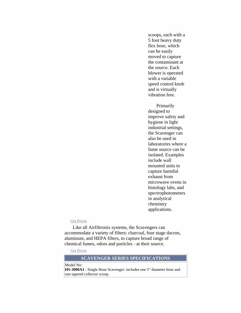
scoops, each with a 5 foot heavy duty flex hose, which can be easily moved to capture the contaminant at the source. Each blower is operated with a variable speed control knob and is virtually vibration free. Primarily designed to improve safety and hygiene in light industrial settings, the Scavenger can also be used in laboratories where a fume source can be isolated. Examples include wall mounted units to capture harmful exhaust from microwave ovens in histology labs, and spectrophotometers in analytical chemistry applications.
Get Prices
Like all Airfiltronix systems, the Scavengers can accommodate a variety of filters: charcoal, four stage dacron, aluminum, and HEPA filters, to capture broad range of chemical fumes, odors and particles - at their source. Get Prices
SCAVENGER SERIES SPECIFICATIONS Model No: HS-3000A1 - Single Hose Scavenger: includes one 5" diameter hose and one tapered collector scoop.

HS-3000A2 - Double Hose Scavenger: includes two 5" diameter hoses and 2 tapered collector scoops. Blower Dimensions: - 16" H x 12.5"D x 23.5" W Hose: - 5" diameter heavy duty chemical resistant PVC flexible hose. Single 5 foot length for HS300OAl and double 5 foot lengths for HS-3000A2 Standard Nozzles: - Wedge shaped Nozzles measure 9.5" D x 6.5"H, sloping to 3.5" H x 6.5" W (custom scoops and other adapters available) Power Requirements: - 115V AC, 100 Watts, 50/60 Hz, 230V AC optional for export. Weight: - HS-300OAl - 37 lbs. HS-300OA2 - 43 lbs. Noise Level: - A weighted noise level 68 dB at 1 meter Custom Variations: - We can manufacture the scavenger series in many different configurations (i.e. wall mounted blower, mini-hood with hose attachment, unique adapter fabricated to attach to existing equipment - please call to discuss your special application). Scavenger Options:
• Wall Mount Kit • Additional Flex Hose 5" Diameter • Blocked Filter Alarm Unit • Outside Vent Adapter Kit • Stainless Steel Cart • Carry Handle
Airflow Performance StatisticsUnit HS-3000A1 HS-3000A2
Get Prices
Filters Installed Max
Airflow CFM
Face Velocity
FPM
Max Airflow CFM
Face Velocity
FPM None 173 1275 273 1010 HEPA 118 870 154 565 HEPA/Dacron/.5" Carbon 116 850 143 525
HEPA/Dacron/2" 94 690 110 405

Carbon 0.5" Carbon 156 1150 228 840 2" Carbon 110 812 160 590 2 each - 2" Carbon 94 690 120 440
All numbers refer to average readings taken at full blower speed NOTE: For filter info see our Filter Page Get Prices
Home || Introduction || Products || What's New || Contact Us
AIRFILTRONIX CORP. 154 Huron Avenue Clifton, NJ 07013
Phone: 973.779.5577 Toll Free: 800.452.8510
Fax: 973.779.5954 [email protected]
Web Design by:

H-1
Appendix H. Tiger-Vac® Vacuum Cleaner

MERCURY RECOVERY VACUUM CLEANER SYSTEMS
FOR WET AND DRY RECOVERY
MRV-16
ALL STAINLESS STEEL CONSTRUCTION
STATIC FREE AND ESD SAFE
HEPA FILTER EFFICIENCY 99.99% ON 0.3 MICRONS
MRV-16
SPECIFICATIONS:
Models
Part No HP
1 Phase/Volts
@ 60 HZ Amps
Vacuum
Pressure at
Sealed Orifice
H2O
Airflow
CFM/l/s
MRV-16
110800A 1.6 120 10.5 110" 110/48
Recovery Capacity of Mercury Recovery Jar: 20 ounces (591ml)
Recovery Capacity: Dry: 5 gallons (19 litres)
Liquids: 12.5 gallons (50 litres)
Suction Orifice on all models: 1.5" (38mm)
Models
Part No KW
1 Phase/Volts
@ 50 HZ Amps
Vacuum
Pressure at
Sealed Orifice
mm H20
Airflow
l/s
MRV-16
110800B 1.05 240 5 2100 48
Recovery Capacity of Mercury Recovery Jar: 591 millilitres
Recovery Capacity: Dry: 19 litres
Liquids: 50 litres
Suction Orifice : 38mm
list activated carbon and picture

Design Application
- Mercury Recovery Vacuum Cleaner System for wet and dry recovery
- All Stainless Steel Construction with an autoc lavable recovery tank.
- Hour Counter
- Internal HEPA Filter 99.99% efficiency on 0.3 micron.
- Suction hose with Mercury Separator
Special Features and Specifications
A. Mercury Separator & detachable mercury
recovery jar: Separates the liquid mercury and
directs it into the recovery jar. The mercury
separator is made of stainless steel for
excellent corrosion resistance and easy
decontamination. Separator assembly includes
2 jars.
B. Houst Counter / Timer: Facilitates the
measuring of the carbon filter life.
C. Floater: Cuts-off suction when recovered
liquids reach capacity level.
1. Poly liner: Clear poly line (6 mil) disposable,
to facilitate recovery and disposal.
2. Paper Filter Bag: Disposable paper filter
bag with latex micro-liner, on micron efficiency.
Facilitates recovery and disposal.
3. Double Cloth Filter: Washable, one micron
efficiency.
4. HEPA Filter: 99.99% efficiency on 0.3
microns
5. Carbon Cartridge Assembly: For the
adsorption of mercury vapors and odors. Designed to completely adsorb mercury vapors for one hour of continuous
exposure. After one hour of exposure the concentrations of mercury vapors will begin to rise above 0.000 mg/M3.
Once the carbon has been exposed to mercury vapors for one hour, it is the operator’s responsibility to ensure that the
exhaust air falls within permissible exposure limits. The recommended device is the Jerome brand mercury analyzer
or othe similar devices. (Not included with the vacuum cleaner.
6. Liquid Filter: Made of polypropylene mesh. Prevents large particles from being sucked-up during liquid recovery.
More Special Features and Specifications
- All models include Suction hose with Mercury Separator
- All units include a Carbon Cartridge Assembly filled with 18 lbs (8kg) of 3mm Mersorb brand carbon for the
adsorption of mercury fumes and odors.
- Noise level of vacuum cleaner at high speed is 70 dB (A) @ 6.5 ft (2m).
- EMI/RFI Shielded with electronic filter suppressor for Class B computing devices.
- Static free / ESD safe
WARNING!
Not to be used to vacuum up flammable or ignitable materials or dusts.
Do not use this vacuum cleaner in hazardous locations.
Please consult out technical representatives if an Explosion Proof / Dust Ignition Proof vacuum cleaner is
needed for hazardous locations.

I-1
Appendix I. Peristaltic Pump
Peristaltic Pump Test Results Date: Mon, 3 May 1999 16:27:45 -0400 To: [email protected], [email protected], [email protected], [email protected], [email protected], [email protected], [email protected], [email protected], [email protected], [email protected], [email protected], [email protected], [email protected], [email protected], [email protected] From: Van Graves <[email protected]> Subject: Mercury Pumping Results On April 30, Phil Spampinato and myself were able to test the ability of our tubing pump to remove mercury from one of the Y-12 flasks. With the help of Eric Manneschmidt we were able to transfer mercury between containers and obtain some rough estimates of pumping rates. Some pictures of the pumping equipment are shown below, and I've included some notes we jotted down. But the bottom line is that this technique seems to be a safe, efficient, and ergonomic method of loading mercury into the TTF storage tanks. The pumping equipment was purchased from Cole-Palmer and consists of a removable pump head mounted to a variable-speed, bi-directional drive motor. Flexible Tygon tubing is inserted in between rollers in the pump head. These rollers pinch the tubing, creating a vacuum and pulling mercury through the tube. Thus, only the tubing comes in contact with the liquid, so the pump equipment is not contaminated. In our experiment we used plastic hose clamps to connect the flexible tubing to a section of rigid stainless tubing that was used as a dip tube for the mercury flasks. The other end of the flexible tubing was left open to empty into another container; for actual loading operations it would be connected to some rigid pipe which drained into the storage tank. In our initial tests with water we were able to achieve a maximum flow rate of approximately 0.15 liters/sec. With mercury, the best flow rate we could get was 0.03 l/s, based on rough volume and time measurements. At this flow rate we could expect to empty a flask in 75 seconds. Hence, it appears that the Hg loading operation can be accomplished in less than half of the two-week estimate envisioned for pouring the flasks. Other items of interest: * Due to the way the pump works, once air enters the dip tube, vacuum is lost, and any mercury remaining in the dip tube will fall back into the flask. In our experiment the leftover quantity was approximately 15 ml. Over the entire 540 flasks, this equates to less than one liter not being transferred. To keep this quantity to a

I-2
minimum, the top of the dip tube needs to be the highest point in the system. We also plan on slightly tipping the pallets to maximize the amount of mercury pulled from the flasks before suction is lost. * When removing the dip tube from the flask, no dripping was observed. This should minimize the possibility of contaminating the exterior of any flasks or of the pallet. We plan on wiping the dip tube with cheesecloth as it's removed from each flask to further reduce the risk of drips. * The pump has an "occlusion adjustment" that controls how tightly the pump rollers pinch the tubing and the amount vacuum created. The standard setting worked well with water but was not enough to start the mercury flow. Increasing the setting solved this problem, but it has the side effect of reducing the tubing life. Once flow is initiated the adjustment can be decreased without losing flow. Since tubing failure seems to be the worst accident envisioned we will periodically replace the tubing or move it to a different position so the rollers aren't wearing on the same tube location. * This test was originally scheduled to be done in Rusi Taleyarkhan's lab at the Engineering Technology Division. Once the equipment was set up, we found that we were unable to remove the plug from the flask using available tools. From discussions with Y-12 personnel, many of the plugs have been put on using an impact wrench, and in addition the plugs are somewhat rusty. Removing the plugs without taking the flasks from the pallet may be the most difficult part of this process. We hope they can be removed the same way they were inserted and will try this when the mercury flasks are on site.

I-3
Figure H-1. Tube pump test setup; M & C Division fume hood.

I-4
Figure H-2. Pump under operation with mercury in the tube.

K-1
Appendix K. Material Safety Data Sheets

Material Safety Data Sheet
Print date: 04/07/2005 Revision date: 04/07/2005Version: 5
1. COMPANY AND PRODUCT IDENTIFICATION Product code: 014113-03 02Product name: QUINTOLUBRIC® 888 46
2. COMPOSITION/INFORMATION ON INGREDIENTS
HAZARDOUS COMPONENTS
This product does not contain any hazardous ingredients as defined under 29 CFR 1910.1200.
3. HAZARDS IDENTIFICATION
Emergency OverviewMild eye irritation.
May cause skin irritation and/or dermatitis.May cause irritation of respiratory tract.
May be harmful if swallowed. Principle routes of exposure: Eyes, skin and inhalation. Signal word: CAUTION Eye contact: May cause slight irritation. Skin contact: Substance may cause slight skin irritation. Inhalation: Vapors and/or aerosols which may be formed at elevated temperatures may be
irritating to eyes and respiratory tract. Ingestion: Ingestion may cause gastrointestinal irritation, nausea, vomiting and diarrhoea. Physico-chemical properties: No hazards resulting from material as supplied.
_____________________________________________________________________________________ SDS code: 014113-03 02
Supplier:Quaker Chemical Corporation Quaker Park One 901 Hector Street Conshohocken, PA 19428 610-832-4000 E-mail: [email protected]
Product name: QUINTOLUBRIC® 888 46 Page 1 of 7
Emergency telephone number:* 24 HOUR TRANSPORTATION:**CHEMTREC: 1-800-424-9300 703-527-3887 (Call collect outside of US)* 24 HOUR EMERGENCY HEALTH & SAFETY:**QUAKER CHEMICAL CORPORATION: (800) 523-7010( Within US only)Outside of US call (703) 527-3887

4. FIRST AID MEASURES General advice: If symptoms persist, call a physician. INJECTION INJURY WARNING: If product is
injected into or under the skin, or into any part of the body, regardless of the appearance of the wound or its size, the individual should be evaluated immediately by a physician as a surgical emergency. Even though initial symptoms from high pressure injection may be minimal or absent, early surgical treatment within the first few hours may significantly reduce the ultimate extent of the injury.
Eye contact: Rinse immediately with plenty of water, also under the eyelids, for at least 15
minutes. If symptoms persist, call a physician. Skin contact: Wash off immediately with soap and plenty of water. If skin irritation persists, call a
physician. Ingestion: If swallowed, seek medical advice immediately and show this container or label.
Never give anything by mouth to an unconscious person. Inhalation: Move to fresh air in case of accidental inhalation of vapors. If not breathing, give
artificial respiration. If breathing is difficult, give oxygen. Consult a physician. Notes to physician: Treat symptomatically. Medical condition aggravated by exposure:
Dermatitis.
5. FIRE-FIGHTING MEASURES
Suitable extinguishing media:
Use dry chemical, CO2, water spray or `alcohol` foam.
Unusual hazards: None known Special protective equipment for fire-fighters: As in any fire, wear self-contained breathing apparatus
pressure-demand, MSHA/NIOSH (approved or equivalent) and full protective gear.
Specific methods: Water mist may be used to cool closed containers.
6. ACCIDENTAL RELEASE MEASURES Personal precautions: Ensure adequate ventilation. Environmental precautions: Do not flush into surface water or sanitary sewer system. Methods for cleaning up: Soak up with inert absorbent material (e.g. sand, silica gel, acid binder, universal
binder, sawdust).
7. HANDLING AND STORAGE Handling
_____________________________________________________________________________________
Flammable limits in air - lower (%): Not determined
Flash point (°C): 260 Flash point (°F): 500
SDS code: 014113-03 02 Product name: QUINTOLUBRIC® 888 46 Page 2 of 7
Flammable limits in air - upper (%): Not determined
Flash Point Method: COC
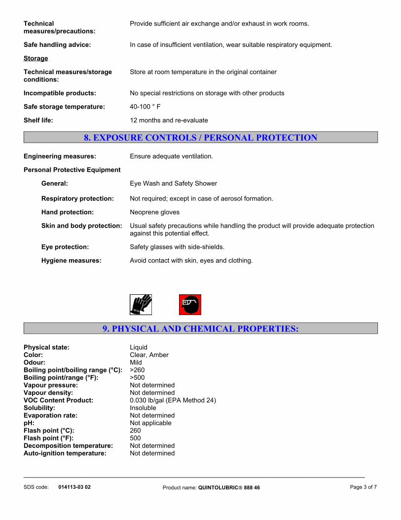
Technical measures/precautions:
Provide sufficient air exchange and/or exhaust in work rooms.
Safe handling advice: In case of insufficient ventilation, wear suitable respiratory equipment. Storage Technical measures/storage conditions:
Store at room temperature in the original container
Incompatible products: No special restrictions on storage with other products Safe storage temperature: 40-100 ° F Shelf life: 12 months and re-evaluate
8. EXPOSURE CONTROLS / PERSONAL PROTECTION Engineering measures: Ensure adequate ventilation. Personal Protective Equipment General: Eye Wash and Safety Shower Respiratory protection: Not required; except in case of aerosol formation. Hand protection: Neoprene gloves Skin and body protection: Usual safety precautions while handling the product will provide adequate protection
against this potential effect. Eye protection: Safety glasses with side-shields. Hygiene measures: Avoid contact with skin, eyes and clothing.
9. PHYSICAL AND CHEMICAL PROPERTIES:
Physical state: LiquidColor: Clear, AmberOdour: MildBoiling point/boiling range (°C): >260Boiling point/range (°F): >500Vapour pressure: Not determinedVapour density: Not determinedVOC Content Product: 0.030 lb/gal (EPA Method 24)Solubility: InsolubleEvaporation rate: Not determinedpH: Not applicableFlash point (°C): 260Flash point (°F): 500Decomposition temperature: Not determinedAuto-ignition temperature: Not determined _____________________________________________________________________________________
Product name: QUINTOLUBRIC® 888 46014113-03 02 Page 3 of 7 SDS code:

Density @ 15.5 ° C (g/cc) : 0.911Bulk density @ 60 ° F (lb/gal): 7.60Partition coefficient (n-octanol/water, log Pow):
Not determined
Explosive properties: - upper limit: No data available - lower limit: No data available
10. STABILITY AND REACTIVITY Conditions to avoid:
None known Materials to avoid:
Strong oxidising agents Hazardous decomposition products:
Nitrogen oxides (nox), Oxides of phosphorus, Carbon oxides, Sulphur oxides Stability:
Stable under recommended storage conditions. Polymerization:
Not applicable
11. TOXICOLOGICAL INFORMATION Oral toxicity (rats): Practically non-toxic (LD50>10ml/kg). Based on testing of the product or a similar product.Inhalation toxicity (rats): practically non-toxic (LC50>200ml/kg). Based on testing the product or a similar product.Eye irritation (rabbits): Essentially a non-irritant (Draize score = 0). Based on testing of the product or a similar product.Skin irritation (rabbits): Slighlty irritating (Primary Irritation Index = 1.46). Based on testing of the product or a similar product.
Human Patch Skin Study: Not an irritant or a sensitizer (Modified Shelanski). Based on testing of the product or a similar product.
12. ECOLOGICAL INFORMATION Persistence and degradability: Environmental Fate and Effects: Under the modified Sturm Test (40 CFR 796.3620),
this product is readily biodegradable. Mobility: No data available Bioaccumulation: No data available Ecotoxicity effects: No data available Aquatic toxicity: Aquatic Toxicity: Acute LC/EC50 (fish) - this product is non-toxic (LC50 > 2000ppm)
based on testing of this product or a similar product. _____________________________________________________________________________________
Product name: QUINTOLUBRIC® 888 46014113-03 02 Page 4 of 7 SDS code:

13. DISPOSAL CONSIDERATIONS Waste from residues/unused products:
Waste disposal must be in accordance with appropriate Federal, State, and local regulations. This product, if unaltered by use, may be disposed of by treatment at a permitted facility or as advised by your local hazardous waste regulatory authority.
Contaminated packaging: Do not re-use empty containers Methods for cleaning up: Take up mechanically and collect in suitable container for disposal.
14. TRANSPORT INFORMATION U. S. DEPARTMENT OF TRANSPORTATION: Proper shipping name: Not Regulated Shipping Desciption: TDG (CANADA): Proper shipping name: Not Regulated IMDG/IMO: Proper shipping name: Not Regulated IATA/ICAO: Proper shipping name: Not Regulated
15. REGULATORY INFORMATION CLASSIFICATION AND LABELING OSHA Hazard Communication Standard:
This product is considered non-hazardous under the OSHA Hazard Communication Standard.
Canada - WHMIS Classification Information:
This product has been classified according to the hazard criteria of the CPR and the MSDS contains all the information required by the CPR.
Product Classification: None Required Product Classification
Graphic(s): Component Classification
Data: Canadian National Pollution
Inventory Data: U.S. REGULATIONS: SARA (311, 312) hazard class: This product possesses the following SARA Hazard Categories: Immediate Health (Acute): No Delayed Health (Chronic): No _____________________________________________________________________________________
Product name: QUINTOLUBRIC® 888 46014113-03 02 Page 5 of 7 SDS code:

Flammability: No Pressure: No Reactivity: No RCRA Status Not Regulated
STATE REGULATIONS (RTK): California Proposition 65 Status: No components are listed
INVENTORY STATUS: United States TSCA - Sect. 8(b) Inventory: This product complies with TSCA Canada DSL Inventory List - DSL Compliance has not been determined EC No. Compliance has not been determined
16. OTHER INFORMATION Sources of key data used to compile the data sheet:
Material safety data sheets of the ingredients.
Reason for revision: This data sheet contains changes from the previous version in section(s) 4 Prepared by: Quaker Chemical Corporation -Safety, Health and Environmental Affairs Group - US
* Indicates possible chronic heath effect Personal protection recommendations should be reviewed by purchasers. Workplace conditions are important factors in specifying adequate protection.
_____________________________________________________________________________________
Flammability: 1
Health: 1
Reactivity: 0
HMIS classification:
Reactivity: 0
Personal Protection: B
Health: 1
SDS code: 014113-03 02
Special: NA
Product name: QUINTOLUBRIC® 888 46 Page 6 of 7
NFPA rating:
Flammability: 1

DisclaimerThis product's safety information is provided to assist our customers in assessing compliance with safety/health/environmental regulations. The information contained herein is based on data available to us and is believed to be accurate. However, no warranty of merchantability, fitness for any use, or any other warranty is expressed or implied regarding the accuracy of this data, the results to be obtained from the use thereof, or the hazards connected with the use of the product. Since the use of this product is within the exclusive control of the user, it is the user's obligation to determine the conditions for safe use of the product. Such conditions should comply with all regulations concerning the product. Quaker Chemical Corporation ("Quaker") assumes no liability for any injury or damage, direct or consequential, resulting from the use of this product unless such injury or damage is attributable to the gross negligence of Quaker.
End of Safety Data Sheet
_____________________________________________________________________________________
Product name: QUINTOLUBRIC® 888 46014113-03 02 Page 7 of 7 SDS code:

Material Safety Data Sheet U.S. Department of Labor Occupational Safety and Health Administration Form Approved OMB No. 1218-0072 This form is used to comply with OSHA's Hazard Communication Standard,
Calgon Carbon Corporation
29 CFR 1910.1200. Product Type: Impregnated Activated Carbon - CB II SECTION I Barnebey Sutcliffe Corporation Emergency Telephone Number
614-258-9501 835 North Cassady Avenue Telephone Number for Information
614-258-9501 Columbus, Ohio 43216 Date Prepared
3/6/03
Signature of Preparer (optional)
SECTION II - HAZARD INGREDIENTS/IDENTITY INFORMATION Hazardous Components (Specific Chemical Identity; Common Name(s))
OSHA PEL
ACGIH TLV
CAS %
Activated Carbon Not Defined
Not Defined 7440-44-0 > 75%
Potassium Iodide 7681-11-0 <10% Triethylene Diamine 280-57-9 < 5% Silver 7440-22-4 < 1.1% Copper Chloride 13933-17-0 < 25% Sodium Hydroxide 1310-73-2 < 8% Potassium Hydroxide 1310-58-3 < 10% Diammonium Molybdate 27546-07-02 < 5% Nickel Chloride 7718-54-9 < 25% Copper Oxide 01317-38-0 <12% Phosphoric Acid 7664-38-2 < 20% Sulfur 7704-34-9 < 25% Iodine 7553-56-2 < 15% Iron Oxide 1307-37-1 <20% Sulfuric Acid 7664-93-9 <20% Citric Acid 77-92-9 <20% SECTION III - PHYSICAL/CHEMICAL CHARACTERISTICS Boiling Point NA Specific Gravity 0.4 – 0.9 Vapor Pressure (mm Hg.) 0 Melting Point NA

Vapor Density (AIR = 1) Solid Evaporation Rate NA Solubility in Water Soluble Impregnant Appearance and Odor Black granules, powder or pellets SECTION IV - FIRE AND EXPLOSION HAZARD DATA Flash Point NA
Flammable Limits Ignition Temperature > 220 oC
LEL NA
UEL NA
Extinguishing Media Large volumes of water or inert gas Special Fire Fighting Procedures None SECTION V - REACTIVITY DATA Stability Unstable Stable
XX
Conditions to Avoid High concentrations of organics in air will cause temperature rise due to heat of adsorption. At very high concentration levels this could cause a bed fire. High concentrations of ketones and aldehydes can cause a bed temperature rise due to adsorption and oxidation.
Incompatibility (Materials to Avoid) Strong oxidizers such as ozone, oxygen, permanganate, chlorine. Hazardous Decomposition or Byproducts Carbon monoxide may be generated in a fire. Hazardous Polymerization
May Occur
Will Not Occur XX
Conditions to Avoid None
SECTION VI - HEALTH HAZARD DATA Route(s) of Entry: Inhalation?
Irritation of respiratory system by dust and carbon fines
Skin? May cause skin irritation
Ingestion? May irritate digestive tract
Health Hazards (Acute and Chronic) Possible eye injury from dust exposure. Effect of long term exposure to dust on respiratory system has not been defined. Carcinogenicity: NA
NTP? NA
IARC Monographs? NA
OSHA Regulated? NA
Signs and Symptoms of Exposure Irritation of eyes and respiratory system may result from exposure to carbon fines Medical Conditions Generally Aggravated by Exposure NA Emergency and First Aid Procedures For eye contact, immediately flush with copious amounts of water for at least 15 minutes and seek medical attention. For inhalation, fresh air and rest. For skin contact, wash with soap and

water. For ingestion, treat as for ingestion of impregnant. SECTION VII - PRECAUTIONS FOR SAFE HANDLING AND USE Steps to Be Taken in Case Material is Released or Spilled Sweep or shovel up carbon into closed container. Discard, repackage or recycle. Report in accordance with local, state and federal regulations. Waste Disposal Method Dispose of carbon in accordance with local, state and federal regulations. Precautions to Be taken in Handling and Storing Wet activated carbon removes oxygen from air posing a hazard to workers inside carbon vessels or enclosed/confined spaces. Before entering such an area, sample air to assure sufficient oxygen supply. Use work procedures for low oxygen levels, observing all local, state and federal regulations. SECTION VIII - CONTROL MEASURES Respiratory Proctection (Specify Type) NIOSH approved particulate filter if dust in generated in handling. Ventilation
Local Exhaust Recommended
Special
Mechanical (General) Recommended
Other
Protective Gloves Rubber or latex gloves
Eye Protection Safety glasses or goggles
Other Protective Clothing or Equipment As needed. Work/Hygienic Practices Avoid generation of dust in handling. Avoid skin and eye contact.