Appendix 7 Tenants Technical Requirements (On Station)
53
Transport for London Appendix 7 Tenants Technical Requirements (On Station) Rules and Requirements for working on TfL Commercial Properties within a station Transport for London 3 rd September 2018
Transcript of Appendix 7 Tenants Technical Requirements (On Station)
Transport for London
Appendix 7 Tenants Technical Requirements (On Station)
Rules and Requirements for working on TfL Commercial Properties within a station
Transport for London 3rd September 2018

1 Introduction ............................................................................. 2
2 Fire Regulation & Services ........................................................ 3
3 Station Fabric & Security ........................................................ 14
4 Electrical Services .................................................................. 24
5 Mechanical Services ............................................................... 38
6 Appendices ........................................................................... 49
7 Document Submission ........................................................... 50

Introduction ____________________________________________________________________________________________________________________
2
1 Introduction1.1 Intended Use This document is intended for use by:
• Tenants and their fit-out teams, including Designers, Building Services consultants and contractors.
• Suppliers and their project delivery teams. The document is split into sections covering:
• Fire Safety. • Building Fabric. • Building Services. • Check List of Required Documents.
1.2 Background We recognise that tenants often have designs that are proven and established across their portfolio. While we acknowledge this, we require some modifications to ensure compatibility with TfL Standards to protect our building, transport operations, and London’s sustainability. In particular there are legal requirements relating to Fire Safety which are covered in Section 2. This Technical Guide states our mandatory requirements and provides best practice guidance to be followed by you, and shows where there can be flexibility with your fit-out.
Methods on how to satisfy the mandatory requirements are generally included, as well as help in understanding the Sub-Surface Regulations. Where your project team proposes to use an alternative design approach, this must be discussed with your TfL Project Manager for approval. TfL has certain criteria for materials used underground, and more information on Approved Products for use in your fit out can be found by following this link: www.lu-apr.co.uk/Pages/Logon.aspx
1.3 Sustainability and Environmental Protection TfL is committed to minimising the impact of its business on the environment and local communities, and we expect tenants to do the same. TfL strives to act as responsible stewards of the environment at all times by applying the principles of sustainable development in the planning, design, operation and decommissioning of our facilities and services. Society, and therefore government are putting increasing importance on environmental issues through new legislation, policies and taxes. TfL supports this, and believe that a responsible approach to environmental management is fundamental for everyone.
___________________________________________________________________________________________________ Appendix 7 Technical Requirements - v1

Fire Regulation & Services ____________________________________________________________________________________________________________________
3
2 Fire Regulation & ServicesCompliance with fire regulations on TfL premises is more complex than other locations you may be used to, and you may need to seek assistance from a TfL Fire Engineer who has specialist knowledge of our Standards and fire safety legislation relating to TfL premises. The main areas of legislation that you may need to comply with are; (1) The Building Regulations (Approved Document B) (2) The Regulatory Reform (Fire Safety) Order 2005 (RRO) (3) The Fire Precautions (Sub-surface Railway Stations) England Regulations 2009 (4) Transport for London Fire Engineering Standards and typical installation guides
2.1 Building Regulations Transport for London is a “Statutory Undertaking” with respect to Building Regulations, and has its own Building Control Department for on-station projects only. For work on stations, you do not have to apply to a local authority, but you do have to give details of your building proposals to TfL’s Building Control Department for approval. For all non-station projects, you will need to use either the Local Authority, or an approved Building Control Body. Compliance with the fire safety sections of Building Regulations in TfL premises is generally as set out in Approved Document B,
(shops are purpose group 4 in ADB, and railway stations are purpose group 5 in ADB). However, there are special requirements on TfL premises for; construction materials, fire separation, fire detection, fire suppression, electrical wiring, and the fire safety performance of materials. These special requirements are set out in the fire safety legislation and standards that apply to TfL premises, and guidance on these is given below.
2.2 The Regulatory Reform (Fire Safety) Order 2005 (RRO)
Compliance with the RRO on TfL’s premises requires a fire risk assessment to be undertaken by the employer, and is generally similar to that for other premises. You must provide your fire risk assessment to TfL regardless of how many employees you may have in any one property. Guidance to employers is issued by the Department of Communities and Local Government (DCLG) (Guide 11 deals with Transport premises and facilities, and Guide 1 deals with Offices & Shops), and these are available online from the DCLG website. You will need to comply with both sets of guidance when locating a retail premises on TfL stations.
___________________________________________________________________________________________________ Appendix 7 Technical Requirements - v1

Fire Regulation & Services ____________________________________________________________________________________________________________________
4
Fire suppression systems are not generally required on surface stations, but some of them do have special requirements for the fire safety performance of materials (for sub-surface Stations see below). TfL’s fire engineering document “Standard 1-086: Fire Safety Classification of Stations” contains a list of the stations with special requirements, and a copy of this is available from your TfL Project Manager.
2.3 The Fire Precautions (Sub-surface Railway Stations) England Regulations 2009.
Certain TfL stations are defined as “sub-surface” under The Fire Precautions (Sub-surface Railway Stations) England Regulations 2009 (The Sub-surface Regulations). These are prescriptive regulations and compliance is mandatory. The Sub-surface Regulations are fully explained in “Guidance Note 3: Fire safety on sub-surface railway stations” issued by DCLG. If you are locating a retail unit on a sub-surface station there are additional fire safety measures required, over and above those for surface stations, these regulations apply to any type and size of retail unit. Any sub-surface retail unit will need to submit a “S1088” application (there is more information contained in Section 2.7) – and your TfL Project Manager can help you with this process. The S1088 applications have to be approved by the London Fire Brigade, but must still be submitted to the TfL Fire Compliance Team.
All retail units on sub-surface stations will have to be fitted with automatic fire detection systems and voice alarm systems connected to the station’s systems. They must also be fitted with sprinklers or a similar fire suppression system, and are subject to strict controls over construction materials and finishes. The fire systems must be designed and installed to meet TfL’s Fire Engineering Standards, by competent engineers who have third party accreditation for installing such systems. The final connections to TfL systems must be carried out by TfL’s fire system maintenance engineers, with your installer in attendance at the same time. The London Fire Brigade may exceptionally grant exemptions from the need to comply with certain parts of the Sub-surface Regulations, but this would only usually be given for very small retail units that are deemed to be of very low risk. Any exemptions granted may be subject to conditions. The materials used in the construction of an internal wall or ceiling e.g. the studs and boards in a plasterboard partition, or the grid and tiles of a suspended ceiling must be of “limited combustibility” as defined in the guidance to the regulations. There is a very strict definition of what is meant by limited combustibility, and this is given in the Guidance Note as reproduced below.
___________________________________________________________________________________________________ Appendix 7 Technical Requirements - v1

Fire Regulation & Services ____________________________________________________________________________________________________________________
5
Definitions of non-combustible materials
Performance determined using British Standards
Performance determined using European Standards
a) Any material which when tested to BS 476-11: 1982, does not flame nor cause any rise in the temperature on either the centre (specimen) or furnace thermocouples.
a) Any material classified as Class A1 in accordance with BS EN 13501-1: 2002 Fire classification of construction products and building elements, Part 1 – Classification using data from reaction to fire tests.
Definitions of non-combustible materials
Performance determined using British Standards
Performance determined using European Standards
b) Totally inorganic materials such as concrete, fired clay, ceramics, metals, plaster and masonry containing not more than 1% by weight or volume of organic material. (Use in buildings of combustible metals such as magnesium/aluminium alloys should be assessed in each individual case).
b) Products made from one or more of the materials considered as Class A1 without the need for testing as defined in Commission Decision 2003/424/EC of 6th June 2003 amending Decision 96/603/EC establishing the list of products belonging to Class A1 “No contribution to fire” provided for in the Decision 94/611/EC implementing Article of the Council Directive 89/106/ EEC on construction products. None of the materials shall contain more than 1% by weight or volume (whichever is the more onerous) of homogeneously distributed organic material.
c) Concrete bricks or blocks meeting BS EN 771-1: 2003.
___________________________________________________________________________________________________ Appendix 7 Technical Requirements - v1

Fire Regulation & Services ____________________________________________________________________________________________________________________
6
Definitions of non-combustible materials
Performance determined using British Standards
Performance determined using European Standards
d) Products classified as noncombustible under BS 476-4: 1970
In addition to the above, there are separate requirements for the fire safety performance of materials used as finishes in a tenancy. The Guidance Note to the Regulations states that material to be used as finishes must meet the requirements of National Class 0 or European Class B-s3, d2 or better as defined in the table below which has been adapted from ADB.
National Class 0 or European Class B-s3, d2 or better
Performance determined using British Standards
Performance determined using European Standards
1) Non-combustible materials as defined in national class of Table 2 (NR8 (1)).
Any material classified as Class B-s3, d2 or better in accordance with BS EN 13501-1: 2002 Fire classification of construction products and building elements, Part 1 – Classification using data from reaction to fire tests
2) If the material or the surface of a composite product is either:
a) composed throughout of materials of limited combustibility (defined in national class of Table 1 (NR8 (1)); or
b) when tested in accordance with British Standard 476:Part 7: 1987 achieves a class 1 performance and, when tested in accordance with British Standard 476: Part 6: 1989, has an index of performance (I) not exceeding 12 and sub-index (II) not exceeding 6.
___________________________________________________________________________________________________ Appendix 7 Technical Requirements - v1

Fire Regulation & Services ____________________________________________________________________________________________________________________
7
2.4 TfL Standard 1085 - Fire Safety Performance of Materials
TfL has many old stations, where the fire engineering design would not meet modern requirements. Because of this, compensatory measures are applied to protect the public and employees on its stations. The most important of these is a strict control over the fire safety of materials used in these stations (as set out in Standard 1-085). These requirements include compliance with the Sub-surface Regulations. This standard specifies the requirements for materials installed in underground locations with regard to: a) Flammability (including the risk of explosion); b) Smoke emission; c) Toxic fume emission All the construction and wall finishes to be used in the construction of tenancies must comply with this standard. This includes the electrical wiring, and any internal partitions or structural items that are custom built from timber based construction materials. The materials tests must be carried out specifically to meet TfL’s materials standards, by a third party accredited European test house. No other tests will be acceptable. Instead, it is recommended that all materials be selected from TfL list of pre-approved materials, which can be found here: www.lu-apr.co.uk/Pages/Logon.aspx Your TfL Project Manager can provide advice on materials, including those that may have been recently approved but not yet added.
TfL Standard 1-085 does not apply to the following list of items within tenancies when the unit is fitted with fire detection and a fire suppression system: retail stock, consumables, equipment, portable furniture and personal effects. The words “equipment”, and “portable furniture” shall in this context be interpreted to mean any cabinets (including refrigerated cabinets), shelving units, counters, fittings, or furniture that the tenant may bring onto site as a complete pre- manufactured unit, even if these need to be fixed in place when in use.
• ‘portable’ timber furniture must pass European Class B and must be treated off site (not within the station).
• All fabrics and upholstery items must pass BS5852, BS5971, BS5972 and BS6807 (minimum Source/Crib5)
All fit-out designs shall be accompanied by proposed material technical datasheets and the associated test house data for items not on the Approved Products Register. Some activities are unlikely to be permitted in sub-surface units. Examples include frying, whether deep or shallow; sale of: fireworks; lighter fluid; or butane aerosols; and shoe repair using solvent-based adhesives. This is not an exhaustive list - if in doubt, check with your TfL Project Manager. It should be noted that the risks associated with any particular work to your tenancy will be considered during the S1088 application process. Consideration of an application may require additional controls on the materials, or type of stock to be permitted due to the location of the unit on a station (e.g. where a unit may pose a risk to the sole means of escape route from a station).
___________________________________________________________________________________________________ Appendix 7 Technical Requirements - v1

Fire Regulation & Services ____________________________________________________________________________________________________________________
8
2.5 Compliance with Fire Precautions and Process for Change (S1088 Procedure)
Because compliance with fire legislation on railway premises requires specialist knowledge, TfL has its own standard procedure for controlling compliance with fire regulations. This procedure is the “S1088 Fire Safety Precautions – Compliance with Fire Precautions and Process for Change”. Compliance with the S1088 procedure is mandatory on all TfL stations. It is required for both permanent and temporary works, and must include the details of any hoardings which may be erected to carry out those works. S1088 applications have to be made in a standard format, and the application will be forward to the relevant team within TfL by your TfL Project Manager. The S1088 application needs to be accompanied by a Works Impact Fire Risk Assessment (WIFRA) or, for more complex changes, a Fire Strategy Report. A “Design Plan” also needs to be prepared, to accompany the application, based on the station’s fire compliance plans. These documents need to be prepared and signed by a TfL accredited Fire Engineer. An application under the S1088 procedure takes a minimum of 10 working days for approval to start work, the time taken will be longer if it is a complex scheme. This is because the Fire Team will need to prepare CAD drawings in a special format for approval by the London Fire Brigade. If the application is not clearly drawn up, or if the London Fire Brigade requires further information, the approval will be delayed. Once the application has been approved, you will receive an “Approval Notice” and “Approval Plans”; you may only proceed with the works once you have received this approval.
Once the works are complete you will need to apply for an Authority To Use (ATU). This ATU application must be accompanied by an assurance statement, from a TfL Fire Engineer, showing that the work has been completed in compliance with the S1088 application, and with LU’s Fire Engineering Standards. The assurance statement must include a schedule of the materials used in the works, showing evidence of compliance with TfL’s Standard 1-085: Fire Safety Performance of Materials. The ATU process can take up to 3 working days to approve.
2.6 Fire systems - General The fire systems within the tenancy must be installed by a contractor who has third party accreditation, and is approved by TfL, for the type of system being installed. If the system is required to be interfaced with a station system, the final connection must be made by TfL’s fire systems maintenance contractor, with the tenant’s contractor in attendance.
2.7 Fire Detection and Warning Systems. Tenancies in Sub-surface stations must be fitted with an automatic fire detection system and a voice alarm public address system in order to comply with the Sub-surface Regulations. The systems must be interfaced with the station systems and therefore you must use the current TfL detection and alarm system supplier. Your TfL project manager can advise you of this system, and a list of approved installers.
___________________________________________________________________________________________________ Appendix 7 Technical Requirements - v1
Fire Regulation & Services ____________________________________________________________________________________________________________________
9
Where a tenancy is to be located on a surface station which has fire detection and / or a fire alarm, the unit must also be interfaced with those systems. It should be noted that not all surface stations have such systems. For units within stations that do not have a detection and alarm system, the requirement of level of protection required will be confirmed within a Fire Risk Assessment and design (to be undertaken by the tenant). The risk assessment and design shall be reviewed and approved by TfL prior to the start of works.
2.8 Commissioning Fire Systems The commissioning process which will includes any new,additional or removed devices on the station detection and alarm system is to be undertaken by the current system maintainer. Application for changes to recorded via the PR0630 procedure. The commissioning process requires an application by the installation company via the TFL fire engineer and project manager which has a procedure timescale of 10-15 working days from application to onsite commissioning. It is strongly advised that this timescale is included in the delivery programme. For further guidance and recommendations please refer to or request a copy of TfL G0103- Fire detection and alarm systems A1.
2.9 Fire Suppression Systems Tenancies in sub-surface stations must be fitted with an automatic fire suppression system which uses water, in order to comply with the Sub-surface Regulations. The system must be interfaced with the station’s fire suppression systems (note that not all stations will have an existing fire suppression system, but you will still need one in the unit). The system must comply with TfL Fire Engineering Standards which, in turn requires compliance with recommendations contained in the relevant British Standards. Tenancies in surface stations do not need to be fitted with an automatic fire suppression system, unless the fire strategy for that station or the unit requires fire suppression in order to protect the means of escape (this would be unusual).
2.10 Passive Fire Protection Some premises will require passive fire protection works; e.g. work to install fire walls and doors to provide fire separation between electrical rooms and the tenancy, or sometimes to provide fire separation between parts of the premises and the station. This includes fire dampers in, or cladding to, any ductwork that passes through the premises, and fire-stopping where cables and pipes pass through fire barriers. Any fire dampers and fire-stopping must use materials selected from the TfL Approved Product List in accordance with whether it is for surface or sub-surface stations, and need to abide by the conditions of use of each material at. Please see the following link: www.lu-apr.co.uk/Pages/Logon.aspx
___________________________________________________________________________________________________ Appendix 7 Technical Requirements - v1

Fire Regulation & Services ____________________________________________________________________________________________________________________
10
Any passive fire protection work that is required must be carried out in compliance with TfL Fire Engineering Standards, and must be carried out by TfL approved contractors who have third party accreditation to show that they are competent for that element of the work (i.e. The LPC, FIRAS, or similar European schemes). A competent fire engineer must provide certification to provide assurance to TfL that this work has been carried out in accordance with TfL’s Fire Engineering Standards. For the avoidance of doubt, expanding “fire-rated” foam is NOT to be used on any TfL property, above or below ground. For further guidance and recommendations please refer to or request a copy of G0102 Fire systems - passive fire protection A1.
2.11 Sprinkler Systems Sprinkler protection must be provided as required by the specific Fire Safety Strategy for that station (a copy of which can be provided by your TfL Project Manager). Sprinkler installations must comply with BS12845 and the LPC Rules. The hazard classification must be Ordinary Hazard Group 3 to Life Safety Standard. All sprinkler heads must be of the fast response type with an RTI of less than 50. Sprinklers must be designed and installed by contractors certified to the Loss Prevention Certification Scheme LPS1048, or other approved third party accreditation scheme, and an BS12845 completion certificate issued for all installations.
Primary sprinkler infrastructure will be provided to just inside the demise line of the tenancy. No secondary stop valves are to be installed within your demise. The Tenant must submit drawings for the sprinkler system to the TfL Project Manager who will pass these to the relevant Fire Safety engineer for approval, and installation may not commence until these have been approved in writing. Final connection from the tenant system to the station system must be carried out by a TfL approved contractor, with the tenant’s contractor in attendance. For further guidance and recommendations, refer to or request a copy of TfL G0101 A1 Fire suppression and fire fighting systems.
2.12 Sprinkler Installation Requirements Sprinkler systems can only be designed and installed by a TfL approved contractor. The sprinkler design will ensure that there is detection below and above a false ceiling (where the space above the ceiling is greater than 800mm). You must ensure that the sprinkler spray pattern is not obstructed by shop fittings or displayed goods, and a distance of 500mm must be kept between a sprinkler head and any obstructions.
___________________________________________________________________________________________________ Appendix 7 Technical Requirements - v1

Fire Regulation & Services ____________________________________________________________________________________________________________________
11
2.13 Operation of Air Movement Systems Under Fire Conditions
Air handling plant must be controlled to operate as follows under fire conditions via a command from the fire alarm system when any call point, smoke or heat detector within the tenancy is activated:
• Supply fan off (electric heater batteries should shut down before fans to allow heat to be dissipated)
• Extract fan off. Except for: • Dual function fans that provide hot smoke extract. • Kitchen extract fans where the fire is in the kitchen. • Where an Ansul (or similar) fire suppression system is
installed – see Section 5.23 for information. • Recirculation dampers move to the fully closed position. • Fresh air dampers and exhaust damper should remain OPEN • Control of extract fan changes over to be from the
Fireman’s Ventilation Control Panel. With the above exceptions, extract fans should be stopped as quickly as possible for the following reasons:
• Hot smoke could damage fans and render them unusable for cold smoke clearance after a fire.
• Hot smoke could unnecessarily trip fire dampers and prevent the system being used for cold smoke extract.
The fire alarm cause and effect proposals for the tenancy must be submitted to TfL for acceptance prior to installation, and must be compatible with the fire strategy for the particular building.
2.14 Duct Mounted Smoke Detection and Control In recirculating AHUs, the duct mounted sensor should be hardwired to the outstation directly controlling the fan motor and put the air handling system into fire control mode as described above. Operation of the smoke detector must also send a signal to the fire alarm system and the building management system (where present). A 3-position Fire Brigade Ventilation Control panel should be provided for each installation. The switch positions should have the following labels and functions: AUTO - System operating in normal automatic control mode OFF - Supply and extract fan stopped. EXTRACT ON - Extract fan running in non-recirculation mode with fresh air damper fully open (variable speed fans must be set at 100% on). Control switches should be hardwired between the extract fan motor starter, or BMS outstation controlling the fan, and the override switches. Where the Fire Brigade Ventilation Control is wired through the BMS outstation the control should continue to function when the outstation is switched off or loses its signal from the head-end. The Fire Brigade Ventilation Control panel should be located beside the fire alarm panel at the building’s fire control point and labelled “Fire Brigade Ventilation Control”.
___________________________________________________________________________________________________ Appendix 7 Technical Requirements - v1

Fire Regulation & Services ____________________________________________________________________________________________________________________
12
2.15 Hoardings – Protection of Premises During Works
The following sections describe what you can and cannot do with different types of hoardings protecting your work site.
2.15.1 Undertaking Work in “Traffic Hours” (NO HOT WORK PERMITTED)
NO HOARDING - Work is limited to within an existing unit with sprinklers and detection still active and in place.
• Existing shop-front has to remain in place. • Painting, decorating, refurbishment and refitting only. • Tools and equipment to be used and stored in area during
the works, and do need not comply with S1-085. • A S1088 application will not be required for this work. • Heat detectors may be temporarily exchanged for smoke
detectors if the substitution request has been signed by a TfL Fire Engineer.
NON-FIRE RATED HOARDING - Work is limited to converting an existing fire compartment with detection.
• The fire suppression must be installed and working before the fire compartment wall is replaced by the shop front.
• All other works to refit the unit should then take place with sprinklers and detection working.
• Tools and equipment to be used and stored in area during the works, and do need not comply with S1-085.
• A change of use will require a S1088 application and WIFRA, which may indicate other fire safety measures are required.
• Isolations of fire equipment during traffic hours will require a S1088 approval, and temporary exemptions from the relevant requirements of the Sub- surface Regulations.
FIRE RATED HOARDING – Required for all works relating to major demolition and construction, including creation of new units within stations, unless within existing fire compartments as described above.
• A S1088 and WIFRA will be required defining the full works package and fire safety features that would be in place.
2.15.2 Undertaking Work in “Engineering Hours” (Hot Work Permitted only if a TfL Permit has been issued)
NO HOARDING – Limited to minor works in an existing unit, or converting an existing fire compartment to a unit.
• This may be undertaken during engineering hours without a hoarding - provided that the premises are back to normal status, or protected by hoardings as above, by the time that traffic hours recommence.
• Detection or suppression may be isolated during engineering hours without a temporary exemption being in place, but only if a BB229 isolations permit application has been approved. (Please ask your TfL Project Manager for assistance with this permit).
___________________________________________________________________________________________________ Appendix 7 Technical Requirements - v1

Fire Regulation & Services ____________________________________________________________________________________________________________________
13
• Note: Protective hoardings or barriers may still be required around the site if required by the safety method statement for the works.
FIRE RATED HOARDING – All works relating to major demolition and construction, including creation of new units within stations, unless within existing fire compartments as described above.
• A S1088 will be required defining the full works package and fire safety features that would be in place.
2.16 Fire Systems During Works In Tenancy During the onsite period when intrusive works are being undertaken, fire detection and suppression systems are to be either isolated or the devices converted to heat detection mode. The procedure for undertaking this shall be managed by the TfL Project Manager with the assistance of the fit out contractor, TfL Fire Engineer and the system’s maintainer. The Project Manager and fit out contractor shall obtain the below information, which shall determine the type of procedure applicable to the works:
• Contractor requesting • Project Manager requesting • Location, and SID number of the room(s) • Duration of works (from - until) • Time when the works are planned to be undertaken • Device numbers
For a programme of works lasting 2 - 3 engineering shifts, then isolations of the system can be in place and undertaken remotely on a daily basis with 24hrs notice required. For programmes greater than 3 shifts and/or works being undertaken during traffic and engineering hours then a smoke to heat conversion is to be implemented. (This is where a detector will activate if it detects heat only). NOTE: Notification to undergo the conversion must be thought of in advance, as the process from initial application to conversion takes 10-15 working days. Note that isolation of detection during traffic hours is not permitted unless an exemption is granted by the Fire Service Unit and London Fire Brigade.
___________________________________________________________________________________________________ Appendix 7 Technical Requirements - v1
Station Fabric & Security ____________________________________________________________________________________________________________________
14
3 Station Fabric & SecurityTo speed up your approvals and construction time, and greatly reduce your construction costs and environmental impact, you are strongly encouraged to keep your design and layout simple. The more partitions you put in, the more fire detection, suppression, alarm sounders, PAVA speakers etc will be needed. These are all costly items, for which you will be responsible – but they have to be to TfL’s high standards. If you put in a suspended ceiling, then you will need addition void-space fire detection and suppression, as well as additional lighting due to a lower ceiling. Increased numbers of walls and ceilings also need more materials for their construction, and this is at odds with TfL’s objectives of reducing London’s environmental impact.
3.1 Energy Efficiency Targets TfL has objectives to reduce emissions and energy use, and requires tenants to act responsibly to the environment throughout the fit out and on-going operation of their unit. Tenants will be required to demonstrate their contribution to this through a sustainability statement, and carbon management plan which must be submitted with the fit out plans.
3.2 Energy Impact Issues For the purposes of good design, compliance with TfL requirements, energy efficiency and comfort, the key issues that must be addressed by any project are as follows:
• Automatic Energy controls • Lighting levels and switching • Correct use of ventilation • Appropriate means of providing heating / cooling
3.3 Energy Use In Catering Kitchens Energy demand for catering facilities are different from those in non-food outlets, and careful consideration will be needed when working in a unique space such as an Underground station. Below are suggestions to help reduce running costs:
• Have a separate electrical circuit for refrigeration equipment that is required to be ON 24 hours/day.
• Have a separate electrical circuit for cooling, ventilation and other equipment so they can be switched OFF out of hours by use of a “last man out” switch.
• Use good quality thermostatic controls and simple time controls so you only use heating / cooling when needed.
___________________________________________________________________________________________________ Appendix 7 Technical Requirements - v1

Station Fabric & Security ____________________________________________________________________________________________________________________
15
• Most cooking equipment does not require long warm up periods, so should be switched on when actually required.
• Extract rates from cooking equipment can be varied according to demand by use of automatic sensors linked to variable speed fans.
3.4 Enhanced Capital Allowances (ECA’s) These enable 100% tax relief in year of purchase, and can be claimed by companies investing in certain materials, plant, and equipment to encourage uptake of energy efficiency. A detailed list of products is available on www.eca.gov.uk . ECA’s are available on many different items, including the following:
• Variable Speed Drives (VSD’s) • Certain fan types • Motors • Pipe insulation • Lighting equipment • Refrigeration equipment
Designers, contractors and cost managers should include the tax benefits associated with claiming ECAs while working out the life-cycle costs for a project.
3.4.1 Energy Efficiency does NOT cost more Energy efficiency needs to be considered in terms of Life Cycle Costs. While a certain design or product may cost less up-front, it may cost more to run, maintain and replace than a different system.
When carrying out Life Cycle Cost analysis, the following key points should be taken into account:
• Is there an existing station system or asset that can be utilised? TfL are very keen to share the use of existing building services to reduce environmental impacts.
• Correct size / duty of plant (kW). • Operational energy consumption (kWh). • Maintenance. • Capital allowances (see section above). • Expected life of plant • Cost of disposal and replacement
It is worth noting that energy efficiency does not automatically mean increased capital budgets.
3.5 Supporting of Services: General Requirements All light fittings, ventilation grilles, diffusers and sprinklers must be independently supported and not supported from suspended ceilings unless the ceiling system and fixings have been specifically designed for this purpose. BS EN13964 (BS8290) provides a code of practice for the design, structural performance installation and maintenance of suspended ceilings. Piped services supports must allow for the loads caused by thermal movement. Where a dedicated support system has been provided by TfL, this must be used for suspension of services, ceiling and secondary grid systems. If in doubt, please consult your TfL Project Manager.
___________________________________________________________________________________________________ Appendix 7 Technical Requirements - v1
Station Fabric & Security ____________________________________________________________________________________________________________________
16
3.6 Services Penetrations Please note that if you intend to make any deep penetrations to walls or floors, you may need a drilling licence. If you are in any doubt then please check with your TfL Project Manager. All penetrations through walls, floors or roofs must be fire stopped to at least 60 minutes fire resistance, or greater if the existing fire rating dictates. All penetrations through floors must be water sealed to prevent leakage through the floor. Pipes must be installed with sleeves built into the floor with puddle flanges and projecting at least 100mm above floor level. Fire dampers must be installed on ductwork penetrating through fire compartments, must be selected from the Approved Products Register, and be installed by a TfL accredited installer. When selecting fire dampers from the APR, check with your TfL Project Manager that the dampers are suitable. Some dampers have lead times that need to be factored into your programme.
3.7 Type of Unit Enclosure There are two primary forms of tenancy unit enclosure:
3.7.1 Island / Pod / Kiosk A standalone self-contained structure, with the only attachment at floor level. The unit may have a dedicated framework within the ceiling void for the suspension of building services and ceilings.
The enclosure may (for fire or aesthetic reasons) have an enclosed roof. In many situations the space over the enclosure is open, and this will need to be considered.
3.7.2 Full Height The enclosure is fitted within the main building envelope. Internal partitions may reach full height, or may stop short just above the ceiling line in the service void, but will be attached to the main building structural slab. With this form of unit, a dedicated framework may have been provided for the suspension of tenant fit out services and ceilings.
3.7.3 Aesthetic Considerations With Island / Pod / Kiosk units, building service connections will either be through the floor, or from the services zone situated high above the enclosure. In this situation services dropping to the unit need to be cosmetically treated with an architectural finish, or other suitable measures taken to mask them from public view.
3.8 Sustainable Use Of Materials Care needs to be taken when ordering materials for the unit fit-out, and the usual practice of contractors over-ordering is to be discouraged. Getting materials deliveries into a station, and waste out of a station is not as straight-forward as other buildings – so the less material that is used, the better.
___________________________________________________________________________________________________ Appendix 7 Technical Requirements - v1
Station Fabric & Security ____________________________________________________________________________________________________________________
17
When selecting materials, preference must be given to selecting from the BRE Green Guide – but for sub-surface stations, the Approved Products Register takes priority. (NOTE: It is possible to get products added to the Register. Please speak with your TfL Project Manager for more information).
3.9 Finishes Within a Tenancy To ensure your design is compliant with sub-surface regulations, please read: S1085 - Fire Safety Performance of Materials. You can obtain a copy from your TfL Project Manager, or by following this weblink here. The below section summarises the S1085 sections.
3.9.1 Walls This section in S1085 refers to applied finishes on separating walls or partitions of units. Internal walls must be risk assessed and discussed with your TfL Project Manager as to whether they need to be built to a TfL standard (30 or 60 minute compartmentation), and all penetrations fire-stopped. Where this is needed, it must be completed by a FIRAS or LPC registered contractor and all works must pass inspection to a TfL recognised standard. Any wall hung panels must be designed so that the system does not allow any deviation which may cause the panels to become dislodged. The system must not allow any deflection which may allow the concealment of any devices or packages. Finger traps must also be avoided where such systems are used.
3.9.2 Permanent Internal Walls Localised lightweight fixtures and fittings (small pictures, poster displays and like) may be attached to existing walls. Display furniture may, if required for reason of safety and stability, be attached to the wall. The fire integrity of the wall must be taken into consideration should wall fixing be necessary.
3.9.3 Fire Doors All Fire Doors within sub-surface stations that lead between a tenancy and station must be steel and installed and accredited by a FIRAS LU approved contractor to 60 minutes. Fire doors used within a fire-suppressed tenancy can be timber (and the use of FSC timber (or similar) is required), but all timber must be treated to BS476 part 6 & 7 before it is brought to site. Retrospective painting or spraying is not allowed. The installation of steel fire doors may require an “I-Beam” metal frame for stability of the wall. Any infills within steel studs to allow door frame fixings must use pressure treated (Dricon) timber.
3.9.4 Ceilings and Ceiling Systems All ceilings with a void of more than 800mm must be protected with sprinkler heads and / or mist system. Where suspended ceilings are used the grid system must be hung on galvanised metal rod or strap hangers. Under no circumstances should wire hangers be used. All hangers and supports must be fixed back to the structural soffit. If this is particularly onerous then a secondary support system must be introduced to avoid fixing to services.
___________________________________________________________________________________________________ Appendix 7 Technical Requirements - v1

Station Fabric & Security ____________________________________________________________________________________________________________________
18
This sub grid must be fixed back to the structural soffit at 1200mm centres. Proof that the sub grid can take the loading of the ceiling system must be provided. All suspension systems must be clearly labelled with the name of the ceiling contractor and the maximum design load must be clearly displayed. If gantries are used above then “fragile” warning signs must be incorporated. No part of the ceiling can be fixed or supported back to any piped services or duct work. A minimum clear height is required within tenancies of 2.4 m between finished floor and underside of any ceiling except in difficult situations where a lower ceiling is necessary. Any suspended ceiling used must conform to BS EN13964 (BS8290 pt 3). And must be regularly inspected (bi-annually) for evidence of sagging. Cables and other services must be independently supported and nothing must be allowed to rest on the ceiling grid. Signage, CCTV, Train Information Systems and the like must all be independently supported back to the building structure. Plasterboard ceilings may have a fire rating, and all penetrations such as access hatches need to maintain the fire rating. Access hatches must be provided in order to allow safe maintenance of any equipment installed within the void either by TfL or the tenant’s maintainers. Any signage within a tenancy must maintain a minimum height of 2.3m above FFL.
3.9.5 Floors BS EN 1365-2 This section of S1085 refers to floor areas in units. It includes raised floors and makes reference to ramps and steps. The nature of the substrate plays a large role in determining the success of the final floor finish. Lateral movement can be accommodated by incorporating movement joints but vertical deflections will seriously damage the floor. Hard finishes should therefore never be laid where there is the possibility of any vertical movement, such as with raised access floors. Due to the strict testing criteria of S1085 - it is advised to select a floor finish that has been tested and is on the APR. Timber flooring is only permitted on sub-surface stations if it has been treated to BS476 part 6 & 7 before it is brought to site. We encourage the use of reclaimed and/or FSC approved timber products for flooring, subject to the above conditions being met.
3.9.5.1 Slip resistance Most types of flooring materials provide adequate slip resistance when they are level and maintained in a clean dry condition and any sealers or polishes have been used correctly. Most types of flooring become slippery in a wet condition. The appearance of being slippery is also an issue and must be considered when selecting a flooring product and highly reflective floors must be avoided. Please refer to the HSE document ‘Assessing the Slip Resistance of Flooring’ for guidance. The Standard requires moderate to low slip potential which translates as 36+,
___________________________________________________________________________________________________ Appendix 7 Technical Requirements - v1

Station Fabric & Security ____________________________________________________________________________________________________________________
19
Pendulum Test Results High slip potential 0 – 24 Moderate slip potential 25 – 35 Low slip potential 36 +
3.9.5.2 Impact resistance The dynamic impact from heavy objects, cases, bottles, point loads from delivery cages etc. will cause damage to hard floors which are not bedded correctly. Even with a solid bed some materials are vulnerable so the use of ceramic tiles is not permitted. Conglomerate stone and some natural products such as granite perform better than ceramics and are therefore acceptable. Resilient floors perform better under impact and in situations where the subfloor has a degree of flex, so this is the recommended solution.
3.9.5.3 Edge trims A metal angle trim must be installed between the Station finishes and the Tenant space. Any change in floor level must be designed out to allow step-free access.
3.10 Glass This refers to: glass used on the frontage; glass for decorative purposes; glass mirrors; and any glass shelving.
3.10.1 General requirements All toughened and laminated glass used in all situations within a TfL building must be permanently marked in a position which will be visible after installation in accordance with BS 6206. The glass must be kite marked in one corner of each individual panel. The following information must be included in the marking;
• British Standard Number BS 6206 • Code to identify the material, T -Toughened, L-Laminated. • Safety class A,B,C • Name or trademark or BSI licence number.
3.10.2 Shelving Glass for shelving must meet all relevant safety requirements and British standards relating to free standing furniture, be mechanically fixed into position, and as a minimum requirement must be toughened. No exposed edges are to be positioned in such a way as to allow injury, in particular consideration should be given to low level shelving or tables, and the relationship to children. Glass fronted cupboards must also use toughened glass. Specialist equipment, display cabinets etc, must have accompanying documentation relating to the specification and performance of the glass. Timber shelving may also be used, but the wood must be treated to BS476 part 6 & 7 before it is brought to site.
___________________________________________________________________________________________________ Appendix 7 Technical Requirements - v1

Station Fabric & Security ____________________________________________________________________________________________________________________
20
3.10.3 Shop fronts This section includes any glass panel, which is greater than 1200mm in height or is fixed above that height and not deemed to be decorative cladding and shall comply to BS 6262-4:2005 Glazing for buildings. Code of practice for safety related to human impact. Due to the busy nature of the TfL network, the following horizontal design loads for vertical glazing shall be applied to all glazing installs over 1200mm.
3.10.3.1 Horizontal loads for vertical glazing Vertical glazing in units shall be designed as non load-bearing partition walls. As vertical glazing is typically not across the line of passenger flows and not adjacent to a sunken area, the loads to be adopted are: i. 1.5 kN/m - Horizontal uniformly distributed line load to be applied at a height of barrier load application of 1200mm. ii. 1.5 kN/m2 - Horizontally distributed load to be applied to the area below the height of barrier load application of 1200mm. iii. 1.5 kN - Point load to be applied at the most onerous point anywhere below the height of barrier load application. (The above loads are not additive and shall be considered as three separate load cases.) Where vertical glazing is across the line of passenger flows and adjacent to a sunken area, the requirements of Clause 3.2.16.7(a)(i) of TfL Standard S1053 Civil Engineering – Building and Station Structures shall be applied.
All glazing must be Toughened (Tempered) /Laminated Glazing, and any glazed panels over 1200mm shall be heat soaked. Any changes to, or additional ironmongery, has to match the specification of the existing ironmongery. There is a designated location for the shop front signage, and additional branding or signage is not permitted. Please see the Retail Design Guide for more information.
3.10.3.2 Glass Fixing Fixing shall be by channels or clamps positioned at top and bottom, and need to be sized appropriately. There needs to be a minimum channel or clamp cover of 1.5 times the glass thicknesses. This needs to be provided with an appropriate glazing gasket or tape, or by an alternative mechanical fixing method of a clamp assisted by adhesive.
3.10.3.3 Glass Joints Joints must be appropriately sized for the glass thickness and live load tolerances but a minimum of 6mm. The glass needs to be mechanically polished and fixed with a high modulus silicone joint which needs to be mechanically finished with a negative scallop and all residues of silicone removed. Where appropriate a taped joint will be considered. Any deviation from these jointing or fixing methods must be backed up with evidence of suitable performance.
___________________________________________________________________________________________________ Appendix 7 Technical Requirements - v1

Station Fabric & Security ____________________________________________________________________________________________________________________
21
3.10.3.4 Type of glass Toughened laminated glass utilising a minimum of a 1.5 PVB (polyvinyl butyral) interlayer, and the minimum thickness to suitable calculations, but no less than 9.5mm in any situation. Glass must have smoke seals fitted. Clear glass types can include: SGG Stadip / Securit or laminated using Pilkington Optifloat toughened. Heat soaking one or more panes is an option if required to reduce possible failure by nickel-sulphide inclusion.
3.10.4 Mirrors This section refers to any glass used as a mirror applied to a base build substrate. The glass for this type of installation should generally be mirrored glass with a safety film applied to the reverse. The specialist film applied to the reverse of the mirror gives the glass a safety performance and specification so that if the mirror is broken the film holds the fragments of glass in place reducing the risk of injury.
3.10.4.1 Joining Mirrors There are two methods of addressing the joints for mirror glass. Any other options should be discussed with your TfL Project Manager. The acceptable joint details are:-
• Open: 2 – 4 mm depending on the glass tolerances and thickness.
• Silicone: 4 – 8 mm filled with high modulus clear silicone.
3.10.4.2 Fixing Mirrors The preferred method of fixing is that the mirror should be bonded over the entire area and adhered to the substrate such as ply which has a minimum thickness of 6mm, using either 3M 468 MP Transfer Tape, or silicone-bonding agents such as Dow Corning 895 structural silicones or 797 silicones. Both are neutral cure products, and need to be evenly distributed over the entire area. Equivalents may be used but evidence must be provided of the performance before using them. Bonding should always be supplemented with adequately designed mechanical fixings such as top and bottom “Z” fixings attached to the substrate (this substrate must be capable of withstanding the appropriate loadings and of accepting the incorporated fixings). Care must be taken to ensure that the mirror film or reverse surface is not compromised by the substrate.
3.11 Timber The use of timber as a sustainable material is very much encouraged, and should always be considered in-lieu of plastic and metals. Timber used must be from a Forestry Stewardship Council (FSC) approved source (or similar approved scheme) is required, but it must meet sub-surface requirements by being treated to BS476 part 6 & 7 before it is brought to site.
___________________________________________________________________________________________________ Appendix 7 Technical Requirements - v1

Station Fabric & Security ____________________________________________________________________________________________________________________
22
The use of MDF is very strongly discouraged due to the production materials used, and the health implications to users and surrounding people when machining the material.
3.12 Roller Shutters Roller shutters should be installed and maintained in accordance with BS EN 13241:2003+A2:2016 and conform to Building Regulations Approved Document B and BS9999. The roller shutter must adhere to the following characteristics:
• Be imperforate to ensure that an adequate smoke seal is created when the shutter is closed.
• In line with Approved Document B, the roller shutter shall close on the activation of a heat or multi-sensor detector located within the immediate vicinity of the shutter.
• Rollers shutters shall be fitted with a visual and audible warning display to provide warning of closure in the event of a fire, they shall also be set to close after a pre-set time which will be advised by the TfL Fire Engineer during the pre-commissioning stage.
• Smoke detection is permissible to initiate closure only when the shutter is intended to partially descend to form part of a boundary to a smoke reservoir.
• Key switches for the shutter shall be installed either side of the roller shutters and must have a battery backup or a manual override (chain or handle) that can be accessed from both sides to allow a fast escape from the unit.
• Roller shutters should be capable of being opened manually by the fire brigade without use of a ladder.
Roller shutters cannot be deemed as the only means of escape unless the shutter is to remain open at all times it is occupied. An alternative means of escape shall be provided within units that require the shutter to be in a closed position at times when tenants are present during pre and post trading periods.
3.13 Beer Cellars and Storerooms (Surface Only) Where a beer cellar or storeroom is to be used to store CO2 cylinders, a local CO2 detector must be installed by the tenant within the storage area. This detector is to be powered from the tenant’s electrical supply but must have a battery back-up. An alarm should be incorporated which will sound if the battery fails or is becoming discharged. All detectors must have a ‘healthy’ green indicator and a fault / alarm indicator.
3.14 Energy Sources for Cooking Any cooking, where permitted must be carried out using electricity. The use of gas is not permitted anywhere on sub-surface stations. Induction cooking is strongly encouraged as it is more efficient and more easily controlled than ceramic hobs.
___________________________________________________________________________________________________ Appendix 7 Technical Requirements - v1

Station Fabric & Security ____________________________________________________________________________________________________________________
23
3.15 Security Considerations Design has an important role to play in preventing crime and reducing criminal activity without compromising the enjoyment and usability of products, places and services by legitimate users. Designers must remain focused on those they are designing for, as well as those they are designing to thwart. Designing out crime is not simply a case of better locks and bolts. For it to be most effective (and cost effective), crime prevention needs to be designed-in at the start of a project. If designers consider the ways in which the object, systems or environments they are designing might be susceptible to crime and terrorism early in the design process, they can prevent incidents from occurring, or at least reduce the opportunities for offender behaviour.
3.16 Waste Management Tenant’s are normally responsible for their own waste management, including storing waste within their demise while waiting collection. For all tenancies, a waste management plan must be provided to TfL for approval, and should include how materials will be segregated for recycling. Where a tenant is to use the station’s waste facilities, this must be approved by TfL in advance, and the station’s recycling system must be followed. The use of re-usable delivery crates is strongly encouraged to reduce the amount of cardboard waste to be disposed of.
___________________________________________________________________________________________________ Appendix 7 Technical Requirements - v1
Electrical Services ____________________________________________________________________________________________________________________
24
4 Electrical Services4.1 Electrical Installations Covered By This
Standard The requirements of this section apply to all electrical installations within tenancies on or connected to LU stations.
For tenancies not on or connected to LU stations, electrical installations should comply with all relevant British Standards (in particular BS7671) and be in accordance with CIBSE recommendations.
It is the responsibility of the tenant to ensure that any equipment installed or used in a property on TfL premises is designed, installed and maintained in accordance with all statutory requirements, however the TfL project team can provide assistance where required and suggest resources or contractors to assist with any phase of the project.
4.2 Control of Information A checklist of documents that need to be produced during the design and installation phases can be found in Section 7.
Copies of electrical test certificates must be available for inspection before switch on, and your supply WILL NOT be energised until these have been provided to your TfL Project Manager.
4.3 Safety, Standards and Statutory Regulations All electrical systems need to be designed to the following regulations and guidance:
• Electricity at Work Regulations • Memorandum of Guidance on the Electricity at Work
Regulations - Health and Safety Executive Booklet HS (R) 25 • BS 7671 IET Wiring Regulations Current Edition • Guidance Notes on the IET Wiring Regulations published by
the IET • Health and Safety at Work Act • The Management of the Health & Safety at Work Regulations • Regulatory Reform (Fire Safety) Order 2005 • Building Regulations England and Wales. • Construction (Design and Management) Regulations (CDM). • Electrical Equipment (safety) Regulations • BS 5266 Emergency Lighting • GVK CIBSE Guide K: Electricity in Buildings • SLL Code for Lighting and SLL Lighting Handbook • TfL Standard S1069
In addition to the documents listed above, other rules and regulations may apply to your tenancy. Please discuss this with your TfL project manager if you have any queries on what you should comply with.
___________________________________________________________________________________________________ Appendix 7 Technical Requirements - v1
Electrical Services ____________________________________________________________________________________________________________________
25
All work on electrical systems shall be carried by competent electricians qualified to the relevant C&G level. All testing shall be carried out by a competent electrician qualified to the relevant C&G level. All electricians working in TfL tenancies shall be a member of UKAS approved professional trade body for the area in which they are working. No works shall be carried out to the electrical system outside of the tenancy.
4.4 Redundant Services All redundant equipment and services (i.e. cabling, switchgear or containment) shall be removed during your works.
4.5 Electrical Supply & Metering The electrical supply to the unit may be either directly from ‘the street’ (via a local DNO) or, when on an LU Station, from the station distribution system. In this instance, the supply will be sub-metered and billed by TfL.
Your TfL Project Manager will confirm what type of supply and metering your unit has.
4.6 Electrical Supply Capacity The design of the electrical system and equipment must always be based on most efficient use of energy. This includes direct electrical
consumption, but also the indirect impact i.e. additional heat load that then needs mitigating.
At the start of the project, your TfL project manager will confirm the load capacity for the unit. You must then establish that the supply provided is of a sufficient capacity to serve the load. If it is found to be inadequate the design must be reviewed and if possible the load reduced to an acceptable level before a request for additional power is made as additional power requests take a long time to approve and arrange.
Where a 3-phase supply is provided the connected loads shall be distributed across the supply phases to achieve a balanced system.
To enhance the level of safety in the event of a circuit failure; lighting shall be interleaved across several circuits and, where applicable, across supply phases.
4.7 Electrical Cupboard All tenants units must have a dedicated room or cupboard to house electrical distribution equipment. The size of the cupboard must comply with the Electricity at Work regulations, with particular attention to access requirements. Distribution board schedules and wiring schematics shall be displayed and be kept up to date.
The cupboard must have a self-closing door, complete with a handle and the correct signage. Where required, all fire resisting cupboards and enclosures are to be installed and certificated by an LU and third party accredited passive fire protection contractor.
___________________________________________________________________________________________________ Appendix 7 Technical Requirements - v1

Electrical Services ____________________________________________________________________________________________________________________
26
In order to comply with the Electricity at Work Regulations, all electrical cupboards shall display the following sign permanently fixed to the outside of the door:
Depending on size of electrical supply and cupboard, consideration should be given to HSE recommended signage and posters.
Where an electrical cupboard is provided by TfL, it will normally contain the following;
• Electrical incoming power supply. • Isolator • Electricity Meter (or this may be located elsewhere in the
station) In addition, the following services may also be located in this cupboard:
• Fire alarm / voice alarm system termination junction box • Fire shutter electrical equipment, if required.
The installation of the final circuit electrical distribution / control equipment within the cupboard can result in an increased heat gain, therefore the equipment / wiring shall be designed to function at the temperature within the cupboard.
TfL staff shall have the right of clear access to the cupboard at any time and the cupboard must remain accessible and shall not have goods stored in front of the cupboard door or in the cupboard.
Small cupboards minimise the risk of inappropriate materials being stored. With the possible exception of large electrical capacity users, requiring a sub-main distribution switchboard, the electrical cupboard need not be a floor to ceiling enclosure.
Water and drainage pipework shall not be run through or terminate in the designated electrical cupboard.
An electrical cupboard should not be provided by the tenant in an area designated as an escape route.
4.7.1 Electrical Cupboards in Subsurface Station
Generally, units protected by live sprinkler suppression and detection system (linked to the station fire detection and alarm system), the cupboard is not required to be of a fire resisting construction. There may be exceptions to this, and your TfL Project Manager will advise if this is the case.
A smoke detector is to be installed within the cupboard to provide early warning.
___________________________________________________________________________________________________ Appendix 7 Technical Requirements - v1

Electrical Services ____________________________________________________________________________________________________________________
27
4.7.2 Electrical Cupboards in Surface stations
Generally, units protected by a live detection system (linked to the station fire detection and alarm system), cupboards are to be constructed of a fire resisting construction to a minimum of 30 minutes. There may be exceptions to this, and your TfL Project Manager will advise if this is the case.
A fire detector is to be installed within the cupboard to provide early warning.
4.8 Electromagnetic Compatibility (EMC) The electrical systems, equipment and plant shall meet the latest EMC regulations and TfL standards. If you are unsure or have any questions regarding EMC please contact your TfL Project Manager.
4.9 Switchgear Distribution boards are to be at a height that provides ease of access without the use of a platform.
Where an electrical supply originates from the station system, a label shall be permanently fixed to the front of each distribution board that identifies the source of supply (switchroom number, SID code and switchgear reference) as well as a unique reference identifying the distribution board.
A circuit chart, identifying the items served, connected load, protection device’s rating, outgoing cable type and size, must be fixed to the inside face of the cover.
The maximum size of a distribution board shall be 12-way TP&N.
If the quantity of required ways exceeds this then consideration should be given to providing a second distribution board.
All incoming supply cables must be fully shrouded to allow work to be undertaken on the board.
When connected to TfL station systems, any distribution board installed must be chosen from the TfL Approved Products Register.
4.10 Circuits
4.10.1 Final Circuits All 13A socket outlet radial and ring circuits shall be protected at the distribution board by RCDs with a 30mA rating, and cash register socket outlets should be on separate circuits from the general ring.
Final circuits shall supply either lighting or small power, not both.
___________________________________________________________________________________________________ Appendix 7 Technical Requirements - v1

Electrical Services ____________________________________________________________________________________________________________________
28
4.10.2 Lighting Circuits
Lighting circuits shall be loop-wired between luminaires with tee-off wiring at final connections only. Lighting in suspended ceilings shall be via plug-in ceiling roses or by an equivalent easy method of isolation and disconnection. The connection between the fixed and the flexible parts must be accessible, and the flex no longer than 500mm.
To prevent MCBs being used as the lighting control, light switches shall be installed external to the electrical cupboard, in an easily accessible location.
4.11 Cables
4.11.1 Cable Selection
• Twin and earth cabling is not to be used on any installation due to its unsuitability for non-residential property.
• Cables shall only be purchased from companies operating under a product certification scheme such as the British Approvals Service for Cables (BASEC).
• For units on TfL train stations, all cables must be selected from the TfL APR. The APR entry will specify whether or not the cables can be used in sub-surface locations.
Cables shall be selected to be suitable for their application. A listing on the APR does necessarily mean that a cable is correct for your installation.
The APR can be found at www.lu-apr.co.uk/Pages/Logon.aspx
• All cabling, installed within the unit must be low smoke halogen free (LSHF). This also applies to wiring in display cabinets, control panels and similar items of equipment within a unit.
• Each circuit shall have its own dedicated neutral conductor. Half-sized neutrals are not to be installed.
• Each circuit shall have its own dedicated CPC. The containment shall not be used as a circuit CPC.
4.11.2 Cable Sizing
• Cable calculations shall be completed to determine the correct cable sizes. The calculations shall include suitable rating factors based on the proposed installation method.
• Lighting circuits shall have a minimum conductor size of 1.5mm2.
• 13A general socket outlet circuits shall have a minimum conductor size of 2.5mm2.
Larger cable sizes may be required depending on the rating of the protective device and load of the circuit in accordance with the requirements of BS7671.
Consideration should be given to the maximum conductor size which the terminal of the equipment can accept.
If conductor sizes are becoming excessive, consideration should be given to reducing the load or area covered by the circuit.
___________________________________________________________________________________________________ Appendix 7 Technical Requirements - v1

Electrical Services ____________________________________________________________________________________________________________________
29
4.11.3 Modular Wiring System
Where used, the design and installation of modular wiring systems shall comply with the following requirements:
• All components and materials shall comply with the relevant British Standards
• To be used for low power consumption circuits only, with a maximum back-up protective device of 32 amps
• The design current of the circuit shall not exceed the current rating of the connectors/plug and sockets
• The inner wires shall be LSF sheathed • The outer sheath shall be metal armour • The system shall be installed in full compliance with the
manufacturer’s instructions • The system shall be accessible throughout and is not to be
installed within a floor screed.
4.11.4 Fibre Optic Cables for Lighting Fibre optic cables used for lighting shall be nonmagnetic/non gel fill type for internal and external use. The fibre cable shall be of loose tube construction, and the fibres shall be formed around a central strength member and constructed with steel wire armour, to provide adequate mechanical protection, and sheathed with an LSHF compound.
Installation of fibre optic cables shall be in accordance with BS7718.
4.11.5 Cable Installation
On sub-surface stations, PVC conduit, trunking or skirting is not permitted for use (even if the trunking is made of an LSF material). All Cable Management Systems (CMS) must be made of a metallic material on a sub-surface station. On escape routes, CMS shall be supported by fire-survivable material.
Cables must never be laid on ceiling systems and must be routed on metallic cable trays and trunking that are appropriately sized to suit the number of cables.
All equipment must be suitably supported so that cables and their connections do not take the weight of any equipment.
Where multiple multicore or armoured cables are run together (3 or more) they shall always be laid on and securely fixed to cable trays for the full length of their run, especially in ceiling and floor voids. To minimise the risk of damage to non-armoured cables, these shall run on cable trays to within 600mm of termination points.
Cables must be attached to trays using purpose made non-flammable cleats, clamps or metal ties.
The following installation methods are considered acceptable:
1. Fixed direct to the surface 2. Fixed onto cable tray or basket 3. Fixed direct onto a channel support system using
appropriate cleats 4. Fixed onto cable ladder.
___________________________________________________________________________________________________ Appendix 7 Technical Requirements - v1
Electrical Services ____________________________________________________________________________________________________________________
30
As a general rule, main and sub-main cables should be laid single depth on the appropriate type of containment system.
All cables are to be installed in a neat, tidy and safe manner in accordance with BS7671. Cables joining or leaving a multiple cable run shall do so in an orderly and logical manner, and must be labelled.
Non-armoured cables shall not be run within wall partitioning without addition mechanical protection.
Cable joints on any type of circuit are not accepted unless express permission is granted by the TfL Project Manager.
4.11.5.1 Final Cable Connections Final connection to fixed items of equipment, including luminaires and heating and ventilation plant, may be by one of the following methods:
• Wiring to heating, ventilation plant and other special equipment should terminate at a switch disconnector or a connection box with fixed terminals local to the equipment.
• Flexible cable from plug-in ceiling rose • Flexible cable from fused connection unit • Single core cables in flexible conduit • Armoured cable with additional loop • Wiring to equipment requiring a single phase supply should
terminate in a fuse connection unit or isolator as appropriate.
Consideration should be given to whether a double pole isolator should be used for certain items of equipment.
Flexible conduits shall be of such length that they do not require supporting in its run and shall be compliant with BS EN 61386-23, and shall be no longer than 1000mm.
Table D3 in Appendix D of the IET’s On-Site Guide provides maximum distances between conduit supports.
Flexible cables for final connections shall have a maximum length of 500mm.
The connection method should suit the situation. Any expected vibration or movement should be allowed for in the length of cable.
4.11.5.2 Segregation of Services
Separate wire ways should be provided for the following services:
• Low Voltage power (circuits of voltages between 50V AC and 1000V AC).
• Fire alarms. • Escape lighting distribution (where a central battery system
is used). • Telecommunication, data, and extra low voltage control
(BMS, CCTV etc.). The minimum distances between different types of cables shall be in accordance with clause 528 of BS7671 and chapter 7.4 of IET Guidance Note 1 - Selection and Erection.
Public Address speaker circuits and microphone cables should be adequately screened to avoid induced signals and cable selection should be undertaken to minimise the effects of electromagnetic interference.
___________________________________________________________________________________________________ Appendix 7 Technical Requirements - v1

Electrical Services ____________________________________________________________________________________________________________________
31
4.12 Labelling
4.12.1 Switchgear and Electrical Equipment Identification
During installation, all distribution boards, switchgear, cables and items of plant shall be clearly labelled at all times, including any temporary items.
All equipment and cabling shall be labelled in accordance with clause 514 of BS 7671. All signs and notices shall comply with the latest version of BS EN ISO 7010.
Where appropriate the label shall indicate the working voltage of the equipment.
Each item of plant shall be provided with operational procedure labels, giving sufficient information to allow the plant to be operated safely and correctly.
Warning labels shall be present when two items of equipment or apparatus are supplied from different phases or are at different voltages and are within 2m of each other, and on all equipment supplied at voltages in excess of 230V AC. The labels shall state the voltage(s) and source(s) of supply.
Warning notices shall be in place where switchgear may be operated remotely to advise that a danger or hazard may result.
Where a single device cannot isolate equipment and/or enclosures, a label shall be fitted to identify the appropriate isolating devices.
All notices, signs and labels used on electrical equipment should preferably be secured using screws with a maximum of four fixing
points, or where appropriate they may be fixed using an approved adhesive (refer to the TfL APR) which will secure the sign such that mechanical damage will not cause it to fall off, but that can be removed using an approved solvent.
It is important to avoid compromising the IP rating of equipment when installing notices, signs and labels.
A warning notice should be fitted to the covers of any terminal boxes stating the following “Live Conductors - Isolate supply before removing” as well as stating the source of the circuit.
It is possible to combine some notices provided that the messages conveyed cannot be confused between each of the statements.
Examples of the type of information to be shown on equipment labels can be found in the following table.
___________________________________________________________________________________________________ Appendix 7 Technical Requirements - v1

Electrical Services ____________________________________________________________________________________________________________________
32
Item Label to show
Switchgear Current rating, voltage, number of poles, supplied from (device identifier) and what it supplies
Distribution Boards
For external door: Current rating, voltage, supplied from (device identifier), lighting or power board
Internal circuit labels: Description of what it supplies, device rating and type
Individual Busbar Chambers
Current rating, voltage, number of poles, supplied from (device identifier).
Contactors Current rating, voltage, number of poles, supplied from (device identifier) and what it supplies, function (i.e. automatic changeover), if there is a bias then the bias supply should be indicated.
Isolators (not spur units):
Current rating, rating of protection device where relevant, voltage, number of poles, supplied from (device identifier) and what it supplies
Control panels Current rating, voltage, number of poles, supplied from (device identifier) and what it supplies.
Unused ways should be labelled “SPARE”
4.12.2 Cables
To enable future tracing, all cables must have a dedicated circuit identification reference which is to be shown on the cable label.
An approved propriety cable labelling system shall be used and fixed in accordance with the manufacturer’s instruction.
The reference system shall sequentially follow on from that given to the supply points provided in your electrical cupboard provided by TfL e.g. the power, fire alarm, public address, & other such services, and all labelling must correspond with as-built record information.
Cables shall be labelled at:
• The start and end of each run, • A change of direction, • Either side of a structure penetration • 10m intervals on continuous runs.
Labels on multiple cables on a common containment shall be located adjacent to one another.
If ceiling voids are to be sprayed, cables shall be masked at a number of points along their length to ensure correct identification of cable markings after completion of this operation.
Where cables are terminated at a distribution board they shall be labelled with the circuit identification reference number. This shall include the neutral and earth cables for any circuit.
All bonding cables connected to the main earth bar should have a label stating ‘Safety Electrical Earth - Do Not Remove‘.
___________________________________________________________________________________________________ Appendix 7 Technical Requirements - v1
Electrical Services ____________________________________________________________________________________________________________________
33
4.12.3 Containment Systems Identification
Tray and containment systems must be labelled to identify the cable service it carries. Typical designated services are ‘Fire Alarms’, ‘Communication Cables’, ‘Power Distribution’ and ‘Escape Lighting’. The labelling shall be clearly visible and carried out in a durable manner. On compartmentalised trunking, labels must be fixed to the cover stating each compartment’s designated service.
Warning notices shall be fitted to all removable covers of joint boxes or terminal boxes, to indicate the presence of live conductors within.
4.13 Fire sealing All fire barriers must be fully installed and maintained immediately on the same day following any construction or refurbishment works.
In the event of future services being installed through the fire barrier, it must be correctly re-established using an approved propriety method.
Expanding foam sealants are NOT acceptable under any circumstances.
Where any single cable, conduit installation, cable tray run or trunking installation penetrate fire compartment walls, there shall be 75mm of mechanical protection either side of the penetration.
Please refer to the fire section of this document for further information on the installation of fire barriers.
4.14 Lighting Retailing is synonymous with bright lighting and eye catching displays. The advantage of retail within the Underground network is that the ambient lighting in stations is not always as bright as a traditional shopping arcade. This means that to make your store stand out from the background, lower than normal light levels can be used. This has the advantage of reducing capital costs and on-going electricity costs.
4.14.1 Luminaire Selection Luminaries (including diffusers/louvres) must be:
• Use LEDs as the light source • Selected from a manufacturer’s standard range (not specially
designed for the project). • Easy to clean and maintain • Simple and fast to install. • Paint finish resistant to discoloration from ultraviolet
radiation • CE marked • Constructed to an ingress protection (IP) rating to suit the
designated environment. • LSF wiring shall be specified within the luminaire. • End caps and other components manufactured from LSF
material if appropriate. This is not required for external areas.
___________________________________________________________________________________________________ Appendix 7 Technical Requirements - v1

Electrical Services ____________________________________________________________________________________________________________________
34
• Fire barriers must be installed for continuous luminaire systems that pass between fire compartments to maintain the building fire integrity.
4.14.2 Luminaire Installation Luminaires shall be supported by a safe and secure method, including louvres, diffusers and removable gear trays which must be fastened with safety chains or cords with adequate slack to allow removal.
All luminaires shall be installed according to the manufacturer’s instructions.
All wiring from the main distribution board to the lighting must adhere to the standards as set out in Section 4.10.2.
4.14.3 Luminaire Control Gear Where remote drivers are used for luminaires, they shall be securely supported and not laid on the ceiling system.
4.14.4 Lighting Energy Performance
The energy consumed by traditional lighting is predominantly converted to heat which results in high cooling loads thereby increasing the requirement for air conditioning.
To work towards TfL’s policy of reduced energy consumption, the lighting installation shall be designed to achieve a minimum of 80 lamp-lumens per circuit watt, or be shown via LENI to be compliant using a lux level of 1000 lux (for retail).
The above values are not very arduous and the designer shall strive to improve on these figures, and will be looked upon favourably by TfL’s Building Control department for doing so.
4.14.5 Lighting Scheme Design The lighting designer must consider the effect the lighting may have on both the able bodied and those with sensory or physical disabilities. Extreme high luminance levels and glare can cause discomfort and result in visual confusion.
The lighting level contrast between the station (often with light levels of around 100 to 200 lux), and the tenancy (traditionally with higher light levels) must be considered. This is to ensure the tenancy does not cause a “dazzle” effect, and that people transferring from one to the other do not suffer a temporary loss of perception while their eyes adjust to differing light levels. Furthermore, too much glare may cause operational issues for safe CCTV coverage of concourse areas.
Luminaires must be positioned ensuring that no safety risks result from lamp and control gear heat emissions.
The ongoing maintenance of the lighting scheme and other nearby equipment must be considered during the design of the scheme.
Further information on lighting on stations can be found in RIS-7701-INS (Rail Industry Standard for Station Infrastructure) and RIS-7702-INS (Rail Industry Standard for Lighting at Stations). These documents provide good practice advice on the ‘efficacy’ required for display and general lighting.
___________________________________________________________________________________________________ Appendix 7 Technical Requirements - v1

Electrical Services ____________________________________________________________________________________________________________________
35
4.14.6 Lighting Controls
“Last man out “switches shall be provided for all units. These should control the lighting along the exit route, as well as controlling plant items (as covered in Section 5.22).
Lighting control shall be provided to enable energy reduction when areas are not in use.
When your unit is closed, you may only leave Display lighting on. This must automatically switch off either when the station closes to the public (for on-station tenancies), or at midnight (for off-station).
4.15 Escape Lighting Emergency escape lighting must be installed within your tenancy in accordance with BS 5266, and shall use LEDs as the light source.
The escape lighting lux levels shall be designed to take into account the tasks being carried out in the space as described in BS 5266-1.
For further guidance on designing emergency lighting systems please refer to CIBSE lighting guide 12.
The difference in general lighting level and emergency lighting level shall be considered to ensure that the time for people’s eyes to adjust to the reduced level of light is as short as possible.
On sub-surface stations, the station concourse has high levels of emergency lighting, and you should ensure that the contrast between the emergency lighting levels inside the unit and outside the unit are in line with CIBSE recommendations.
Emergency lighting testing facilities shall be provided, either by the use of self-testing luminaires, or by the installation of key operated switches. These are to be clearly labelled as to the circuits served.
4.15.1 Self-Contained Luminaries Self-contained escape lighting can be used in your tenancy, and must use LEDs as the light source.
These shall be non-maintained (and therefore not incorporated into general lighting scheme) and the batteries shall be compliant with BS EN 60598-2-22.
Luminaries shall be connected evenly over the available phases.
Other emergency lighting systems may be considered. If you would like to install a different type of emergency lighting system, please discuss this with your TfL Project Manager.
4.16 Advertising Signs, Cabinets and Signage
4.16.1 Advertising Signs and Cabinets Advertising signs and cabinets shall be designed with safety in mind and with consideration of heat build-up and fire protection. These must be designed with good natural ventilation. Termination of wiring and connections to luminaires shall be to the same standard as expected in the rest of the unit.
___________________________________________________________________________________________________ Appendix 7 Technical Requirements - v1

Electrical Services ____________________________________________________________________________________________________________________
36
4.16.2 Illuminated Signage Illuminated shop signs must be designed to the requirements of section 7 of BS 559. In particular, self-contained illuminated signage shall be of a “fixed” nature, and at low voltage, and must be manufactured to conform to BS 4533-102.1. All light sources shall be LED, use suitable heat-sinks, and allow for heat to be dissipated from the fitting. Any signage outside your demise must be compliant with S1085 (Fire Safety of Materials).
4.17 IT and Telecommunication Services The installation of a phone line is the responsibility of the tenant, but must be carried out in liaison with your TfL Project Manager.
4.18 Cooking Equipment Automatic Isolation An emergency switch-off control system must be installed to enable the supply to cooking appliances to be remotely isolated.
4.18.1 Manually Operated Knock-Off Buttons Red, mushroom-head emergency push buttons that cut off the energy supplies to all cook-line equipment must be installed.
These are to be located at kitchen entrances, exits and escape doorways in a visible and easily accessible position, and positions are to be agreed with the station fire officer (co-ordinated by your TfL Project Manager).
To ensure that they are not likely to be confused with other electrical control devices they are to be clearly labelled as emergency knock-off buttons.
A contactor shall be installed to isolate the electrical supply to each individual cooking appliance controlled by the emergency cut-out system. Contactors shall be located in the tenant’s electrical cupboard and be clearly labelled detailing the cooking appliance served.
Other electrical supplies are to remain unaffected (such as lighting and extract fans) by the operation of the emergency button.
The installation of an emergency cut-out push button system does not negate the need to install local isolation switches on the power supplies to appliances.
4.18.2 Fire Suppression Activated Isolation Automatic isolation of the supply to cooking appliances shall be provided for the following functions:
• When the dedicated cook-line fire suppression system is activated, the supply to the cooking equipment must be automatically disabled, but the extract fans must be left running to enable the extinguishant to be drawn into the ductwork to suppress any flame that has spread.
• When the extract fan of a kitchen extract system is not on, or a fault causes the fan to stop, the supply to the cooking equipment must be automatically disabled.
___________________________________________________________________________________________________ Appendix 7 Technical Requirements - v1

Electrical Services ____________________________________________________________________________________________________________________
37
• On activation of any fire alarm device within the tenancy, the supply to all the cooking equipment in the kitchen must be automatically disabled.
Only on restoration to normal operational conditions shall it be possible to reset the supplies to the cooking appliances (i.e. extract fan running / fire alarm system re-set).
Reinstatement of the energy supplies shall be by manual reset at each individual contactor. It shall not be possible to bypass the safety interfaces.
4.19 Maintenance and Safety Considerations
4.19.1 CE Mark All equipment installed shall be fully tested and fit for purpose. Equipment must bear the CE Mark (Conformity European) where purchased within the European Union (EU). For equipment purchased from countries outside the EU where a CE Mark has not been provided, assurances shall be given to us that it conforms to similar tests as those covered by the CE Mark.
4.19.2 Build-up of Dust in Ceiling Voids Ceiling voids shall be designed to allow for future access for maintenance and cleaning. Build-up of dust around luminaires and transformers can become a future fire and health hazard. The tenant must instigate a policy of regular inspections.
Unnecessary activation of the fire alarm system is a huge inconvenience, causes a financial penalty and it is TfL’s aim to minimise these and recover costs wherever possible. A managed cleaning regime could avoid them.
___________________________________________________________________________________________________ Appendix 7 Technical Requirements - v1

Mechanical Services ____________________________________________________________________________________________________________________
38
5 Mechanical Services5.1 Scope and Capacity All mechanical systems need to be designed to the following regulations and guidance:
• Health and Safety at Work Act • The Management of the Health & Safety at Work Regulations • Regulatory Reform (Fire Safety) Order 2005 • Building Regulations England and Wales. • Construction (Design and Management) Regulations (CDM). • Relevant CIBSE Design Guides • TfL Standard S1068
In addition to the documents listed above, other rules and regulations may apply to your tenancy. Please discuss this with your TfL project manager if you have any queries on what you should comply with.
No works shall be carried out to the mechanical system outside of the tenancy.
Base-build building services will be terminated at, or just within, the demise line of the tenancy. The HVAC equipment provided by the tenant must comply with primary services design strategy where this is available.
In some tenancies there may be a need for cooling to control temperature conditions – but first priority must be given to natural ventilation coupled with good layout and design to reduce the need for any cooling. After natural ventilation, then mechanical extract or supply shall be considered. Cooling by refrigerant gas installations shall be a method of last resort, and will have to be justified on a case by case basis, and will have to be properly and professionally sized for the location and cooling loads. Electrical supplies to all HVAC equipment installed under the fit-out must be fed from the Tenant’s distribution board and metered separately in line with CIBSE TM39.
5.2 Energy Management and Efficiency Systems that allow simultaneous heating and cooling to occur must not be used. Time controls must be provided for all heating, cooling and domestic hot water systems and set to prevent these systems operating when the tenancy is unoccupied. The systems must be split across different electrical circuits to enable correct switching to take place.
___________________________________________________________________________________________________ Appendix 7 Technical Requirements - v1

Mechanical Services ____________________________________________________________________________________________________________________
39
It is important that staff are trained on how to use the systems and are aware of the function of various switches. The following are some suggested areas for consideration:
• Clearly label all light switches and make switches accessible. • Provide clearly labelled switches for all plant. • Separately circuit lighting to enable different light levels for:
normal hours of operation; stock taking; window display; and security.
The fit-out installation must be designed and installed to be energy efficient and this needs to be demonstrated in your Energy Strategy document and your Environmental Impact Assessment which need to be submitted to your TfL Project Manager.
5.3 Internal Design Conditions Your tenancy must be designed to meet the internal design conditions shown in the table below.
Area Design temperature ˚C Summer Winter
Catering seating area (no lower than) 24 20 Main tenancy areas (no lower than) 24 20 Rest rooms N/A 18 Toilets N/A 18 Storage area N/A 16
Tenant systems that connect to station systems must be designed to match the capacity of the connection. No heat is to be rejected to concourses or any other area of the building unless agreed by your TfL Project Manager.
5.4 Refrigerated Display Equipment All refrigerated display cabinets should have doors or plastic curtains to trap cold air and reduce energy usage. These are increasingly common, and customers will not be put off. Heat rejection from these units should be considered when designing the unit layout, and external condensers used where practical. If not possible, then rejected heat within the tenancy should be considered for other uses, such as pre-heating domestic hot water, or diverted to an overdoor heater in winter. If not possible, all efforts must be made to extract the heat by natural or mechanical air movement instead of using cooling.
5.5 Refrigerant Selection Equipment designed to contain alternative refrigerant is available for both refrigeration and cooling. These gasses typically have a lower Global Warming Potential, so are lower cost than traditional gasses. When on sub-surface stations, any refrigerant used needs to comply with TfL sub-surface regulations (and R290 and R32 are not currently permitted). If in doubt, please check with your TfL Project Manager.
___________________________________________________________________________________________________ Appendix 7 Technical Requirements - v1

Mechanical Services ____________________________________________________________________________________________________________________
40
5.6 Cooling and Heating Possible cooling / heating solutions available for tenants are (in order of priority):
• Station-wide supply and extract ventilation may be available to your tenancy if there is spare capacity, or where additional capacity can be easily created.
• Condenser or chilled water may be available to connect to, if there is spare capacity. Spare capacity needs to be proven.
• Connection to a station-wide VRV/F system may be possible if there is spare capacity, or where additional capacity can be provided by upgrading the condenser.
• If none of the above are sufficient, then they can be supplemented by split packaged comfort cooling system.
• Low Temperature Hot Water heating from central plant may be available for tenants to use. This will be only be possible if spare capacity is already available.
For all of the above solutions, your TfL Project Manager can provide information on what services and what capacity is available.
5.7 Fan Coil Units All fan coil units are to be provided with a condensation tray that extends under the full width of the cooling coil, the return tube ends and control valve assembly. Condensation trays must be installed with falls to the drain connection.
The drainage pipework from the tray must be run to discharge over a tundish located in an accessible position and the condensate connected to the foul drainage system via traps with a seal depth of at least 150mm. Where plastic hoses are used they must not exceed 1m in length and must be fully supported. Fan coil units must be installed with easy access for replacement of air filters and routine maintenance.
5.8 Connection to Station Condenser /Chilled Water Circuit
Where a station has chilled water or condenser water, and permission to connect has been granted, the new system must be cleaned and dosed prior to being connected to existing system. Proof of pressure testing, flushing, chlorination (where applicable) and dosing must be provided to TfL for approval prior to livening a new connection to an existing TfL system.
5.9 Comfort Air Conditioning Systems Where split systems are required as a last resort, the condenser must be located outdoors. Alternatively, if agreed with your TfL Project Manager, an outdoor unit can be located within a suitable ventilation shaft, but it must be selected from the Approved Products Register.
___________________________________________________________________________________________________ Appendix 7 Technical Requirements - v1

Mechanical Services ____________________________________________________________________________________________________________________
41
5.10 Ventilation Some stations have a fresh air supply you may be able to use. This may be filtered and / or tempered, and you will need confirmation from your TfL Project Manager. All air handling systems, including tenants own, must operate safely under fire conditions and you must refer to Section 2.13 for details. Ventilation systems and ductwork must be designed in accordance with B&ES DW144. Volume control dampers shall be installed to all branches, and no branch shall use a flexible connection any longer than 1000mm. All supply ductwork shall be insulated and labelled with direction of airflow and if air is supply or extract. No grilles shall rest on the ceiling grid without having a suspension cable to prevent them falling, but still allowing removal. Any proposed ventilation system must be submitted for approval by TfL. Details provided should include:
• Sound attenuation, where relevant. • UV and washable type filters. • Multi-stage filter systems. • Drawings and schematics of all ductwork and outlets • Extract rates. • Fire dampers where any ductwork passes through a fire wall. • Access hatches for maintenance as per B&ES TR19 • Confirm interaction with fire alarm system.
Ventilation systems must be provided for areas such as toilets, locker rooms and administration offices.
5.11 Smoke Control Systems If applicable, all smoke ventilation systems are to be compatible with the fire engineering strategy of the building. Please check with your TfL Project Manager if you have any questions regarding this.
5.11.1 Duct Mounted Smoke Detection A duct mounted smoke detector must be provided in all recirculating air handling systems, as required by the Building Regulations and described in BS 9999, to prevent the recirculation of smoke.
5.12 Any Catering Ventilation No matter what size of cooking equipment you are planning on using, you must consider how heat, smells, and steam will be removed from the heating / cooking process. The energy demands of kitchen ventilation can be minimised by:-
• Correctly sizing the ventilation plant for the actual needs • Using variable speed fans with inverter drives to allow for
the fan speed to ramp up and down in response to demand • Reducing to minimum the distance between the hood and
outside • Reducing the pressure drop on the exhaust fan • Selecting an energy efficient fan • Using natural ventilation for make-up air where possible
___________________________________________________________________________________________________ Appendix 7 Technical Requirements - v1

Mechanical Services ____________________________________________________________________________________________________________________
42
Catering outlets must be provided with cooker hoods connected to an extract system, and these must have a washable grease filter installed within the tenant demise. For systems connected to a shared system, the tenant must also install a carbon filter. For certain areas serving food that use a warming oven or industrial microwave, a recirculating cooker hood with washable grease filters may be an acceptable solution. This will be confirmed by your TfL Project Manager. Ventilation rates shall be as defined in the Building regulations approved document F and associated industry guidance documents. Tenants are fully responsible for operation and cleaning of these systems, and must provide certification to their TfL Property Manager that the ductwork has been deep cleaned every 6 months. The provision of services for these areas should be sized according to actual need rather than rule of thumb. All kitchen extract ductwork from a full catering kitchen, must be fire rated and not have any dampers fitted. (Unless they are fire dampers as it passes through fire compartments).
5.12.1 Odour Control Where it is not possible to extract to the outside, then a packaged system that removes odour, smoke, steam and heat must be installed by the tenant. By agreement with your TfL Project Manager, it may be acceptable for this treated air to be vented either back into your own demise, or on to the station concourse.
The type of device used, and the filtration achieved must be approved prior to installation, and evidence must be provided of an on-going maintenance regime. Unauthorised odours, smoke or steam entering the station concourse will result in closure of your premises until the issue is resolved to our satisfaction. All kitchen extract must have Grease, Smoke and Odour control.
• Grease Filter. A washable filter that removes any grease from the cooking process. These must be cleaned on a daily basis, with cleaning logs available for inspection upon demand.
• HEPA Filter. If “Blue smoke” is a problem, a HEPA filter will ensure the removal of smoke to an efficiency of up to 99.997%.
• Activated Carbon Filter. The final stage of filtration absorbs the odorous organic compounds remaining in the air.
Depending on plant location, Planning Permission may be needed, and it is the tenant’s responsibility to do this. Where food re-heaters are used, and / or high levels of steam are produced, then condensing cooker hoods must be installed to prevent the activation of the fire detection and fire suppression systems. The end user is responsible for maintenance of all their systems, which should be in accordance with B&ES document TR/19. Maintenance records shall be made available to TfL.
___________________________________________________________________________________________________ Appendix 7 Technical Requirements - v1
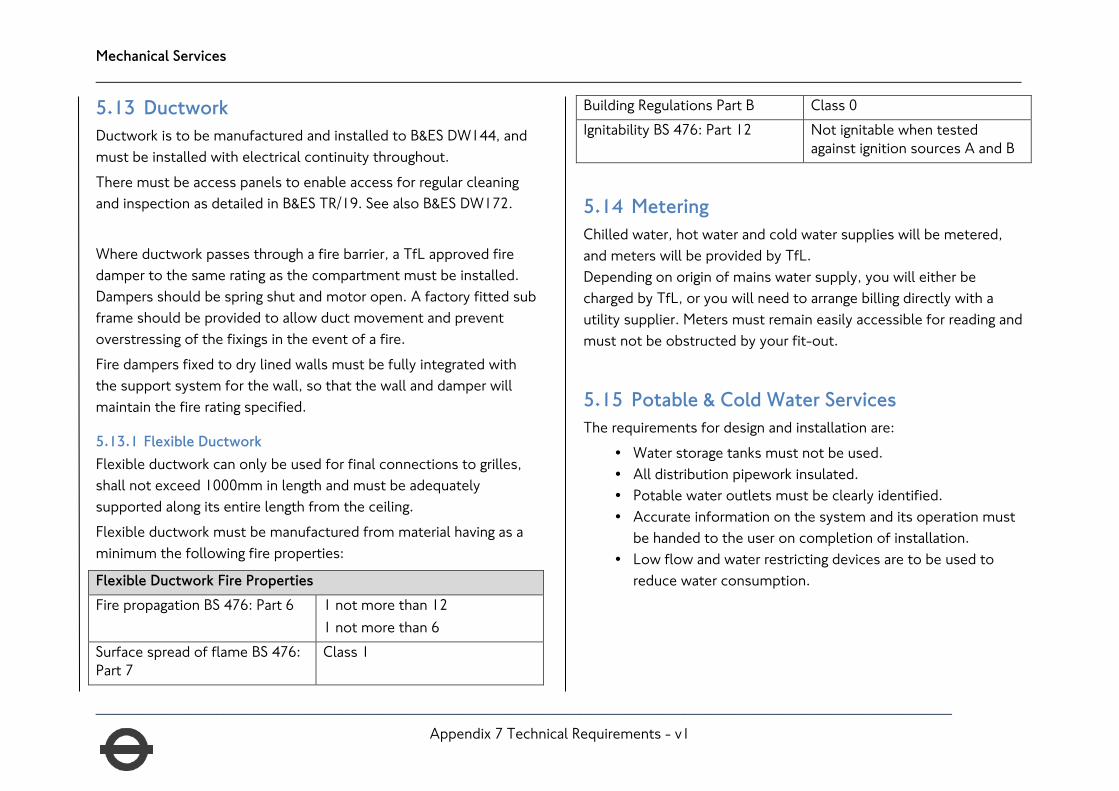
Mechanical Services ____________________________________________________________________________________________________________________
43
5.13 Ductwork Ductwork is to be manufactured and installed to B&ES DW144, and must be installed with electrical continuity throughout. There must be access panels to enable access for regular cleaning and inspection as detailed in B&ES TR/19. See also B&ES DW172. Where ductwork passes through a fire barrier, a TfL approved fire damper to the same rating as the compartment must be installed. Dampers should be spring shut and motor open. A factory fitted sub frame should be provided to allow duct movement and prevent overstressing of the fixings in the event of a fire. Fire dampers fixed to dry lined walls must be fully integrated with the support system for the wall, so that the wall and damper will maintain the fire rating specified.
5.13.1 Flexible Ductwork Flexible ductwork can only be used for final connections to grilles, shall not exceed 1000mm in length and must be adequately supported along its entire length from the ceiling. Flexible ductwork must be manufactured from material having as a minimum the following fire properties:
Flexible Ductwork Fire Properties Fire propagation BS 476: Part 6 1 not more than 12
1 not more than 6 Surface spread of flame BS 476: Part 7
Class 1
Building Regulations Part B Class 0 Ignitability BS 476: Part 12 Not ignitable when tested
against ignition sources A and B
5.14 Metering Chilled water, hot water and cold water supplies will be metered, and meters will be provided by TfL. Depending on origin of mains water supply, you will either be charged by TfL, or you will need to arrange billing directly with a utility supplier. Meters must remain easily accessible for reading and must not be obstructed by your fit-out.
5.15 Potable & Cold Water Services The requirements for design and installation are:
• Water storage tanks must not be used. • All distribution pipework insulated. • Potable water outlets must be clearly identified. • Accurate information on the system and its operation must
be handed to the user on completion of installation. • Low flow and water restricting devices are to be used to
reduce water consumption.
___________________________________________________________________________________________________ Appendix 7 Technical Requirements - v1

Mechanical Services ____________________________________________________________________________________________________________________
44
5.16 Water Quality You must complete a water risk assessment (as per Approved Code of Practice L8), and the results of this need to be shared with your TfL Project Manager. Where a tenancy uses a station water supply a water quality test will be carried out by TfL. Where deemed necessary by the testing, and for all tenancies to be used by food and drink retailers using a station water supply, a UV water filter MUST be installed by the tenant to ensure the quality of the supply. If the tenant requires the water to be softened or treated they will need to provide the necessary equipment to do this.
5.17 Hot Water Services The requirements for design and installation are:-
• A flow and return circulation system must be installed (unless local water heaters within 1m of use location are being used).
• Dead legs to be designed out • Distribution system must maintain circulated water at not
less than 55°C. • Water stored in calorifiers to be maintained at 60°C, except;
• Where water is kept at lower than 60°C for energy conservation, then a weekly pasteurisation cycle must take place out of hours.
• Distribution pipework to be kept to the minimum to avoid unnecessary heat loss, and shall be insulated in all cases from origin to draw-off point, including valves.
• Safety devices to be fitted to prevent scalding or over pressurisation.
• Accurate information on the system and its operation to be handed to the user on completion of the installation.
• Thermostatic Mixing Valves must be installed to all sinks, with the exception of catering washing up sinks, and cleaners sinks.
Hot water taps must be labelled with a warning notice where the water temperature presents a risk of scalding.
5.18 Pipework All pipework must be installed to minimise the risk of microbiological contamination. All main and sub-circuits must be provided with regulating and isolating valves to allow for maintenance and valves must be installed so they are accessible. No joints are to be within any wall, floor or ceiling, and pipes must be adequately supported and allowed to move freely to accommodate thermal expansion. Expansion compensators can be avoided by having changes in the direction of pipework to utilise the natural flexibility of pipework. Drain cocks and air vents must be provided to allow the system to be filled and drained independently of the main station system.
___________________________________________________________________________________________________ Appendix 7 Technical Requirements - v1

Mechanical Services ____________________________________________________________________________________________________________________
45
Automatic air vents must discharge to a permanent drain in a visible, frost free location. Pipe sleeves must be fitted where services penetrate walls, floors and ceilings and must be fire stopped. All pipework penetrations through floors must have pipe sleeves fitted with puddle flanges projecting at least 100mm above the floor so that the penetration is water tight. The materials used must comply with the following table:
Service Normal Bore
Tube Fittings
Low Temperature Hot Water Final Connection
15mm to 50mm
Black MS to BS1387 Medium and Mapress Copper
BS143 and 1256
65mm to 150mm
Black MS to BS1387 Medium
BS1965 Medium
Below 22mm
Copper to BS2871:Part 1 Table X
BS864:Part 2
Waste Copper to BS2871: Part 1 Table X OR BS EN1057-R250, Table 3
Service Normal Bore
Tube Fittings
Chilled Water Final Connections
15mm to 50mm
Black MS to BS1387 Medium and Mapress copper or carbon steel
BS143 and 1256
65mm to 150mm
Black MS to BS1387 Medium
BS1965 Medium
Below 22mm
Copper to BS2871: Part 1, Table X OR BS EN1057-R250, Table 3
BS864: Part 2
Condenser Water 15mm to 50mm
Black MS to BS2871 Mapress copper or carbon steel
BS143 and 1256
65mm to 150mm
Black MS to BS1387 Heavy
BS1965 Heavy
Cooling System Condensate
Copper to BS2871: Part 1, Table X OR Mapress copper or carbon steel
BS864: Part 2
___________________________________________________________________________________________________ Appendix 7 Technical Requirements - v1

Mechanical Services ____________________________________________________________________________________________________________________
46
Service Normal Bore
Tube Fittings
Domestic Hot and cold Water
15mm to 54mm
Copper to BS2871: Part 1, Table X OR BS EN1057-R250, Table 3, and Mapress copper
BS864: Part 2
67mm to 159mm
Copper to BS 2871: Part 1 Table X OR BS EN1057-R250, Table 3
Bronze Weldable
5.19 Drainage Systems The drainage installation must have adequate access points to allow internal cleaning of the system. Access points must not be obstructed by kitchen equipment or shop fittings. Ventilation of systems must be natural, and the use of air admittance valves must be minimised. Above ground drainage systems must have an air pressure test to a positive pressure of at least 40mm water gauge for a minimum period of 5 minutes. Drainage systems must be installed so that stresses of movement of the tenant installation are not transmitted to the station drainage system. Pipe joints must not be embedded in walls or floors.
5.20 Grease Interception Your drainage system must be designed and installed to ensure grease is not discharged into the drainage system. Grease interceptors must be installed for all pot wash and pre-rinse sinks as a minimum and are to have the following features:
• Automatic grease separation and removal to container. • Strainer to separate solids. • 90% minimum grease removal efficiency.
You will not be allowed to trade until this has been proven to be operational, with proof of cleaning and maintenance regime in place.
5.21 Controls All controls necessary for ventilation or cooling must be provided by the tenant. Temperature sensors must be located where they can accurately measure and must not be covered. Unless part of the station-wide system, the tenant’s HVAC systems does not need to interface with the station Building Management System, except in Fire Alarm conditions as described in Section 2.12. A Last Man Out or time-clock system must be used to ensure all non-essential plant and equipment is shut down upon setting of the intruder alarm, or via a final switch on the exit route. The Last Man Out switch should operate via a relay / contactor system to reduce hard-stopping plant, which can cause equipment failures. Many HVAC plant manufacturers provide volt-free contacts to enable Last Man Out type switching.
___________________________________________________________________________________________________ Appendix 7 Technical Requirements - v1

Mechanical Services ____________________________________________________________________________________________________________________
47
5.22 Catering / Cookline Fire Suppression All cooking extract canopies must have a dedicated fire suppression system, such as Ansul, Piranha etc. Plans for their installation must be submitted to your TfL Project Manager for approval. Upon activation (either automatically or manually), the supply air fans must STOP and the extract fans must keep running to draw the extinguishant into the ductwork to supress any flames within the ductwork. You will not be given permission to trade until the completion certificate of the suppression system has been provided, and evidence of an on-going annual maintenance contract is in place.
5.23 Noise and vibration The tenant fit out must not increase the noise level in areas outside your demise. The transmission of airborne noise and vibration from plant and equipment must be attenuated. Any plant installed remotely from the tenancy (for example, roof mounted fans, air conditioning condensers) must not increase noise levels locally.
5.24 Putting Pipework and Ductwork Into Service All ductwork must be clean before it is put into service in line with the definitions in B&ES TR19.
All water pipework should be pressure tested to at least one and a half times the maximum working pressure of the system for a minimum period of four hours without loss of pressure. All new pipe work installations are to be flushed and cleaned in accordance with CIBSE Commissioning Code W and BSRIA Application Guide 8/91 before putting into service.
• Disinfection must include all cisterns, calorifiers and water heaters.
• All heating pipe work is to be treated internally before commissioning, firstly to remove corrosion products and then to inhibit corrosion.
• Following the cleaning procedure and after the systems have been refilled and dosed, test samples are to be taken as required by BAG 8/91 Table 4 - Acceptable limits for sample water test results.
Your TfL Project Manager will require evidence that the systems have been flushed and chemically cleaned before your system can be opened up to the station system. All contaminated water drained from systems must be discharged to meet local authority and water company requirements or removed from site and disposed of responsibly. When connecting to station systems, a re-balancing of the full system may be required. This will be completed by a TfL contractor, but possibly at your cost. You need to let us know when the system is ready for this, and you will also need to provide your system schematic for this purpose. This should include flowrates on each branch and at each outlet, valve identification, and pipe / duct sizes.
___________________________________________________________________________________________________ Appendix 7 Technical Requirements - v1

Mechanical Services ____________________________________________________________________________________________________________________
48
5.25 Maintenance Access All tenant and TfL balancing dampers, fire dampers, sensors, valves, controllers, drain cocks and the like must be easily accessible for adjustment and maintenance. Fire dampers must have visual status indicators and access doors provided for inspection.
5.26 Thermal Insulation Thermal insulation is to be installed in accordance with BS5422 and BS5790. Insulation must be applied pipework and valves to reduce energy losses and condensation risk. Ductwork insulation must be applied to supply and recirculation air ductwork where the in duct air temperature is significantly above or below the surrounding air temperature to prevent energy losses, and all unheated fresh air ductwork to avoid condensation. Where pipework or ductwork passes through a partition, the insulation must continue through the wall to minimise heat loss and prevent condensation from forming, but observing fire-stopping. Insulation, its surface finishes and claddings, and all adhesives, coatings, surface finishes, mastics, sealers and primers used must have as a minimum the following properties fire properties:
• Fire Propagation: BS476: Part 6, • Surface Spread of Flame: BS476: Part 7, Class 1 • Building Regulations: Part B, Class 0 • Ignitability: BS 476: Part 12, not ignitable against when
tested against ignition sources A and B
Where insulation passes through fire compartment walls it must be classified under BS476: Part 4 as Non-combustible and must be installed to provide at least the same fire resistance as the wall.
5.27 Identification
5.27.1 Pipework All pipework must be identified in accordance with BS1710 and labels must be securely attached, and not fade or fall off over time. All valves must be provided with a Traffolyte (or similar) label with a valve number that corresponds to a valve chart or record drawing. The label must show the valve function and on large installations the area it serves. Refrigerant pipework must be clearly labelled with the F-gas present, and the system served.
5.27.2 Ductwork Ventilation systems (including plant) are to be identified as per B&ES DW144, and include the following:
• The plant asset number. • Whether duct is exhaust, extract or recirculation. • Area served by zone branch ducts.
External remote plant such as condensers and AHUs, must be labelled to indicate function, the tenancy, and the area served. Any plant that contains refrigerant shall be labelled with the type and weight of refrigerant used with labels and inks that will not fade with exposure to the sun.
___________________________________________________________________________________________________ Appendix 7 Technical Requirements - v1
Appendices ____________________________________________________________________________________________________________________
49
6 Appendices These documents are updated on a regular basis, so have not been included within this document, but are referenced below. Please contact your TfL Project Manager for the latest version.
• S1552 QUENSH (Quality Environment Safety and Health) This states the conditions to be adhered to whilst on TfL premises.
• S1068: Mechanical Building Services, Utility Provision and Energy Management. This document lays out the standards of installation required for mechanical installations, as well as what is permitted on TfL properties and systems.
• S1069: Low Voltage Electrical Installations This document lays out the standards of installation required for electrical installations, as well as what is permitted on TfL properties and systems.
• S1085: Fire Safety Performance of Materials. • Fire Systems Reference Manual Part 2: Passive Fire Protection Systems • CR07076_G Timber concession (for use in the construction of timber fire doors in underground stations) • Movement License details and application process
Once you are open and trading within a station, you will need permission to move your goods / waste to and from your demise.
___________________________________________________________________________________________________ Appendix 7 Technical Requirements - v1
Document Submission ____________________________________________________________________________________________________________________
50
7 Document Submission 7.1 Approval Times As a large organisation with a focus on safety, due diligence is key in approving your documents. The below table shows the typical approval times for certain key documents that need to be submitted to your TfL Project Manager, with more detailed information in the Section 7.2.
Item Typical Timeframe for TfL to Action Notes
TfL Building Control Application Up to 14 days Only for on-station projects. This is completed by your TfL Project Manager, and is
a chargeable item.
Worksite Fire Risk Assessment This is to show that you have considered evacuation routes and fire minimisation for your construction phase.
Tenancy Fire Risk Assessment Shows how compartmentation will be set out, how evacuations will take place, etc.
S1088 10 Days This TfL document shows that you are compliant with TfL fire regulations.
Completed by your TfL Project Manager, with input from your documents.
Concept Design Plan Up to 10 days Equivalent to RIBA Stage 2, this is to show TfL your initial layouts and suggestions so that we can help you on matters of compliance and other issues we foresee.
Detailed Design Depends upon complexity
(You are strongly encouraged to keep designs as simple as possible – while still being compliant with TfL Standards)
This should only be started following approval of your Concept Design Plan. This is the equivalent to RIBA Stage 4
Detailed design drawings on suppression and detection must be submitted by the TfL accredited fire company.
___________________________________________________________________________________________________ Appendix 7 Technical Requirements - v1

Document Submission ____________________________________________________________________________________________________________________
51
Item Typical Timeframe for TfL to Action Notes
Form A – Fire Isolation This is used for when you need to isolate the fire detection system within your demise during the fit-out works.
Fire Alarm Cause & Effect This is to show how activation of your alarm will trigger certain events.
Energy Statement 10 days This is to show how you will design your building services, and plug-in devices to minimize energy consumption.
Environmental Impact Assessment 10 days This is to show that all the materials used, and your way of working on this tenancy,
will reduce the impact on the environment as much as possible.
7.2 What to Submit, and When To help speed up your approval process, tenants should submit the following documents:
7.2.1 During Design
• Small power layout drawings (inc. reference to cable and containment to be installed). • Lighting layout drawings, including details of emergency luminaires in accordance with the requirements of BS 5266. • Normal lighting calculations (to evidence that lux levels are in accordance with TfL recommendations). • A load schedule detailing the equipment to be installed and which circuits/phases it will be installed on. This should include expected
diversity figures for each phase. (for larger installations this may include a wiring schematic/schedule). • HVAC Layouts and Calculations. • Method statement/Safe System of Work for the installation. • Programme so that site visits by TfL can be planned.
___________________________________________________________________________________________________ Appendix 7 Technical Requirements - v1

Document Submission ____________________________________________________________________________________________________________________
52
7.2.2 During Works
• During the construction phase, there MUST be site visits carried out by TfL representatives to inspect the works. The number of visits will depend on the complexity of the project, and will be agreed during the pre-start meeting.
• A photo report compiled during installation phase will help evidence that items that cannot easily be viewed on completion (e.g. inside distribution boards, damper settings, above ceilings etc.) have been installed correctly and will minimise the disruption on the snagging visit. The list of photographs required will be agreed at the pre-start meeting.
7.2.3 Approaching Completion
• Signed inspection and test plans/trade check sheets (to declare that the installation has been completed in accordance with all relevant British standards, TfL Standards, and this technical guide).
• Snagging inspections will be carried out near the end of the fit-out process and all items shall be closed out before trading is allowed. • BS 7671 electrical installation certificate (inc. calibration certificates for test instruments used). • BS 5266 Emergency Lighting Certificate. • Health and Safety Risk Assessment for the Unit (to include details of electrical testing regime). • Water Risk Assessment (to include the schematic). • Test Certificates for water and ventilation systems as per section 5.25. • Evidence of on-going maintenance regimes
7.2.4 After Completion
• On-going maintenance records. • Ductwork cleaning records (where applicable). • Periodic electrical test reports. • Records to be provided to your TfL Property Manager.
___________________________________________________________________________________________________ Appendix 7 Technical Requirements - v1