Apollo Experience Report Ground-Support Equipment
27
NASA TE CHNICAL NO TE NASA TN D-7918 00 o * w ? d z c APOLLO EXPERIENCE REPORT - GROUND-SUPPORT EQUIPMENT James S. Cooper Lyndon B. Johnson Space Center Houston, Texas 77058 I NATIONAL AERONAUTICS AND SPACE ADMINISTRATION WASHINGTON, D. C. APRIL 1975
-
Upload
bob-andrepont -
Category
Documents
-
view
224 -
download
0
Transcript of Apollo Experience Report Ground-Support Equipment
8/8/2019 Apollo Experience Report Ground-Support Equipment
http://slidepdf.com/reader/full/apollo-experience-report-ground-support-equipment 1/27
N A S A T E C H N I C A L N O T E NASA TN D-791
00
o*
w
?d
zc
APOLLO EXPERIENCE REPORT -
GROUND-SUPPORT EQUIPMENT
James S. Cooper
Lyndon B. Johnson Space Center
Houston, Texas 77058
N A T I O N A L A E R O N A U T I C S A N D SPA CE A D M I N I S T R A T I O N W A S H I N G T O N , D. C. A P R I L 1 9 7
8/8/2019 Apollo Experience Report Ground-Support Equipment
http://slidepdf.com/reader/full/apollo-experience-report-ground-support-equipment 2/27
1. R e p o r t N o .
NASA TN D-7918
4. T i t l e a n d S u b t i t l e I 5. R e p o r t D a t e
2. G o v e r n m e n t A c c e s si o n No. 3. Rec ip ien t ' s Cata log No.
APOLLO EXPERIENCE REPORTGROUND-SUPPORT EQUIPMENT
7. A u t h o r ( s )
James S. Cooper
A p r i l 1975
JSC- 07482~8. P e r f o r m i n g O r ga n i z a t io n R e p o r t No.
JSC S-415
9. P e r f o r m i n g O r g a n i z a t io n N a m e a n d A d d r e s s
10. W o r k U n i t N o .
914- 50- 00-00-72Lyndon B. Johnson Space CenterHouston, Texas 77058
19. S e c u r i t y C l as s if . ( o f t h i s r e p o r t )
11. C o n t r a c t o r G r a n t No
20 . Securi ty Classi f .
13. Ty p e o f R e p o r t a n d P e r io d C o v e r e d
Technical Note2. Sponsor ing Agenc y Name and Address
14. Sponsor ing Agency Codeational Aeronautics and Space AdministrationWashington, D.C. 20546
25nclassified Unclassified
15. S u p p l e m e n t a r y N o t e s
$3.25
16. Abs t rac t
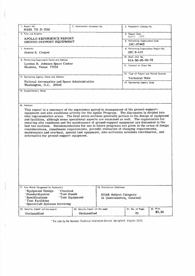
This report is a sum mary of the experience gained in management of the ground-support-equipment and site-re adin ess activity for the Apollo Prog ram . The discussion is divided intonine repres enta tive ar ea s. The fi rs t seven sections generally perta in to the design of equipmentand facilities, although some operational aspects are examined as we l l . The organization f orensuring si te read ine ss and the maintenance of ground-support equipment ar e discussed in thelas t two sections. Recommendations for use in future progra ms are given i n the ar e as of designconsiderations, cleanl iness requirements, periodic evaluation of changing requirements,maintenance and overhaul, specia l te st equipment, site-activation schedule coordination, andsch ema tics fo r ground-support equipment.
18. D i s t r i b u t i o n S t a t e m e n t
STAR Subject Category:12 (Astronautics, General)
8/8/2019 Apollo Experience Report Ground-Support Equipment
http://slidepdf.com/reader/full/apollo-experience-report-ground-support-equipment 3/27
APOLLOEXPERIENCEREPORT
EDITORIAL COMMITTEE
The materi al submitted fo r the Apollo Experience R eports
(a se r i e s of NASA Technical Notes) was reviewed and ap-
proved by a NASA Editorial Review Board at the Lyndon B.
Johnson Space Cen ter consisting of the following member s :
Scott H . Simpkinson (Chairman), Richard R. Baldwin,
James R. Bates, William M. Bland, J r . , Aleck C. Bond,
Robert P. Burt, C hr is C. Cr itzo s, John M. Eggleston,
E. M. Fields, Donald T. Gregory, Edward B. Hamblett, J r . ,Kenneth F. Hecht, David N. Holman (Editor/Secretary),
and Carl R. Huss. The prime reviewer for this reportwas Scott H. Simpkinson.
8/8/2019 Apollo Experience Report Ground-Support Equipment
http://slidepdf.com/reader/full/apollo-experience-report-ground-support-equipment 4/27
CONTENTS
Section
SUMMARY . . . . . . . . . . . . . . . . . . . . . . . . . . . . . . . . . . . .INTRODUCTION . . . . . . . . . . . . . . . . . . . . . . . . . . . . . . . . .
DESIGN STANDARDIZATION . . . . . . . . . . . . . . . . . . . . . . . . . .
Computerized Control Station . . . . . . . . . . . . . . . . . . . . . . . .
Electrical Cables . . . . . . . . . . . . . . . . . . . . . . . . . . . . . . . .
Electrical Terminal Distributors
and Patchable Connectors . . . . . . . . . . . . . . . . . . . . . . . . .
Fluid-Servicing Equipment . . . . . . . . . . . . . . . . . . . . . . . . .
DESIGN INADEQUACIES . . . . . . . . . . . . . . . . . . . . . . . . . . . .
Cryogenic Simplification . . . . . . . . . . . . . . . . . . . . . . . . . . .
Protective Devices . . . . . . . . . . . . . . . . . . . . . . . . . . . . .
Checkout Requirements . . . . . . . . . . . . . . . . . . . . . . . . . . .
Flexible Hoses . . . . . . . . . . . . . . . . . . . . . . . . . . . . . . .
Electrical Connectors . . . . . . . . . . . . . . . . . . . . . . . . . . . .
Electrical Problems . . . . . . . . . . . . . . . . . . . . . . . . . . . . .
Overpressure Problems . . . . . . . . . . . . . . . . . . . . . . . . . . .
GROUND POWER SYSTEM . . . . . . . . . . . . . . . . . . . . . . . . . . .
Direct-Current Ground Power System . . . . . . . . . . . . . . . . . .
Alternating-Current Ground Power System . . . . . . . . . . . . . . . . .
SPECIAL TEST EQUIPMENT . . . . . . . . . . . . . . . . . . . . . . . . . .CLEANLINESS AND ENVIRONMENTAL CONTROL . . . . . . . . . . . . . .
Environmentally Controlled Areas . . . . . . . . . . . . . . . . . . . . .
Fluids . . . . . . . . . . . . . . . . . . . . . . . . . . . . . . . . . . . .
Page
1
1
2
2
3
3
7
7
8
9
9
9
11
11
11
1'1
1 2
12
13
1 4
1 4
1 4
iii
8/8/2019 Apollo Experience Report Ground-Support Equipment
http://slidepdf.com/reader/full/apollo-experience-report-ground-support-equipment 5/27
Section
AUTOMATION . . . . . . . . . . . . . . . . . . . . . . . . . . . . . . . .
Page
14
. . . . . . . . . . . . . . . . . . . . . . . . . . . . . 15utomated Checkout
Automated Servicing . . . . . . . . . . . . . . . . . . . . . . . . . . . . .
COMMON-USE EQUIPMENT . . . . . . . . . . . . . . . . . . . . . . . . . .
MANAGEMENT O F GROUND-SUPPORT EQUIPMENTAND SITE READINESS . . . . . . . . . . . . . . . . . . . . . . . . . . .
MAINTENANCE AND OVERHAUL . . . . . . . . . . . . . . . . . . . .
RECOMMENDATIONS AND CONCLUSIONS . . . . . . . . . . . . . . . . . .
Recommendations . . . . . . . . . . . . . . . . . . . . . . . . . . . . . .
Conclusions . . . . . . . . . . . . . . . . . . . . . . . . . . . . . . . . .REFERENCE . . . . . . . . . . . . . . . . . . . . . . . . . . . . . . . . . .
15
16
16
1
1
1
20
2
iv
8/8/2019 Apollo Experience Report Ground-Support Equipment
http://slidepdf.com/reader/full/apollo-experience-report-ground-support-equipment 6/27
FIGURES
Figure
1 Acceptance checkout equipment (ACE) control room . . . . . . . . .2 Standard 60-conductor cable . . . . . . . . . . . . . . . . . . . . .
3 Standard 38-conductor cable . . . . . . . . . . . . . . . . . . . . .
4 Electrical terminal distributor
(a) Front view . . . . . . . . . . . . . . . . . . . . . . . . . . . .(b) Rearview . . . . . . . . . . . . . . . . . . . . . . . . . . . .
5 Standardized connector installed
(a) Patchable configuration . . . . . . . . . . . . . . . . . . . . .(b) Cable installation . . . . . . . . . . . . . . . . . . . . . . . . .
6 Standardized connector . . . . . . . . . . . . . . . . . . . . . . . .
7 Cryogenic tank . . . . . . . . . . . . . . . . . . . . . . . . . . . .
8 Integrated checkout station . . . . . . . . . . . . . . . . . . . . . .
9 Flexible hose s
10
(a ) Flexible hose a t console . . . . . . . . . . . . . . . . . . . . .
(b ) Flexible hose routing . . . . . . . . . . . . . . . . . . . . . .Har dl ines
(a) Console installation . . . . . . . . . . . . . . . . . . . . . . .(b) Equipment routing . . . . . . . . . . . . . . . . . . . . . . . .
11 Alternating-current to direct- curren t
converter . . . . . . . . . . . . . . . . . . . . . . . . . . . . .
12 Dire ct-c urr ent power supplies . . . . . . . . . . . . . . . . . . .
13 Cleanroom garmen ts . . . . . . . . . . . . . . . . . . . . . . . . .
14 Fuel control panels . . . . . . . . . . . . . . . . . . . . . . . . .
15 Fuel contro l panel details . . . . . . . . . . . . . . . . . . . . . .
Page
2
4
5
6
6
66
7
8
9
10
10
10
10
12
13
14
15
15
V
8/8/2019 Apollo Experience Report Ground-Support Equipment
http://slidepdf.com/reader/full/apollo-experience-report-ground-support-equipment 7/27
APOLLO EXPERIENCE REPORT
GROUND-SUPPORT EQU IPMENT
By James S. Cooper
Lyndon B. Johnson Space Center
S U M M A R Y
The responsibility for ground-support equipment and site re adin ess comprised
the exerci sing of management control over two pr ime space craft contractor s. This
responsibility included providing total capability for vehicle test and checkout at thefactories, development centers, and launch sites, and ensuring operationally ready
faci li ti es and support equipment for each site/facility/vehicle combination.
To meet scheduled prog ram req uiremen ts, unique approaches such as standard-
ization of ca bl es , util ization of common-use equipment, and automation of vehicle
checkout were adopted. The experience gained in the management and development of
ground-support equipment in the ar ea s of design standardization, design inadequacies,
ground power sys te ms, special tes t equipment, cleanl iness and environmental control,
automation, common-use equipment, si te readiness , and maintenance and overhaul
would be beneficial i f applied early i n future programs.
INTRODUCTION
The responsibi lity f or ground-support equipment (GSE) and site r eadiness was
assigne d to an organization within the pol lo Spacecraft Progr am Office. This orga-
nization exercis ed GSE management control over the 'two pr ime spacec raft con trac tor s,
Management responsibility encompassed providing total capability for vehicle test and
checkout at the fac tor ies, development cen ters , and launch site s, and ensuring opera-
tionally ready facilities and support equipment for each site/facility/vehicle combina-
tion.
Several aspects of the GSE program a r e examined in this report. Each aspectw a s importa nt to the development of the total progr am and could mer it presentation
as a se pa ra te report ; however, a more effective presentation r esu lt s fr om combining
them into a single report. The discussion of the Apollo GSE program experience is
followed by recommendations fo r use i n future prog rams . These recommendations
are not linked to specific proble ms; instead, the recommendations are based on gen-
eral pr ac ti ce s that evolved and proved to be useful during the Apollo Program.
8/8/2019 Apollo Experience Report Ground-Support Equipment
http://slidepdf.com/reader/full/apollo-experience-report-ground-support-equipment 8/27
A s an aid to the rea de r, where nece ssa ry the original units of mea sur e have beenconverted to the equivalent value in the SystGme International d'Unit6s (SI). The SIunits are written fi rs t, and the original units a r e written parenthetically t hereaf ter.
D E S I G N S T A N D A R D I Z A T I O N
The GSE sy st ems were designed to support simi la r vehicle tes t req uire men tsand procedures at the various checkout facilities and thus provided the capability toobtain a close correlation of test data and to interchange GSE units among fac ili tie s.Ground- support-equipment end-item design was standardized to reduce the number of
different units, to reduce the GSE manufacturing time, and to reduce the GSE andspacecraft test time. Standardization of the GSE allowed a reduction in the numberof sp ar e par ts requir ed and a reduction in the operating personnel trainin g requi re-ments. Furthe r, the GSE system-standardization approach permitted maximum us eof GSE units among checkout facilities and w a s an important a ss et in meeting thedemanding Apollo schedules.
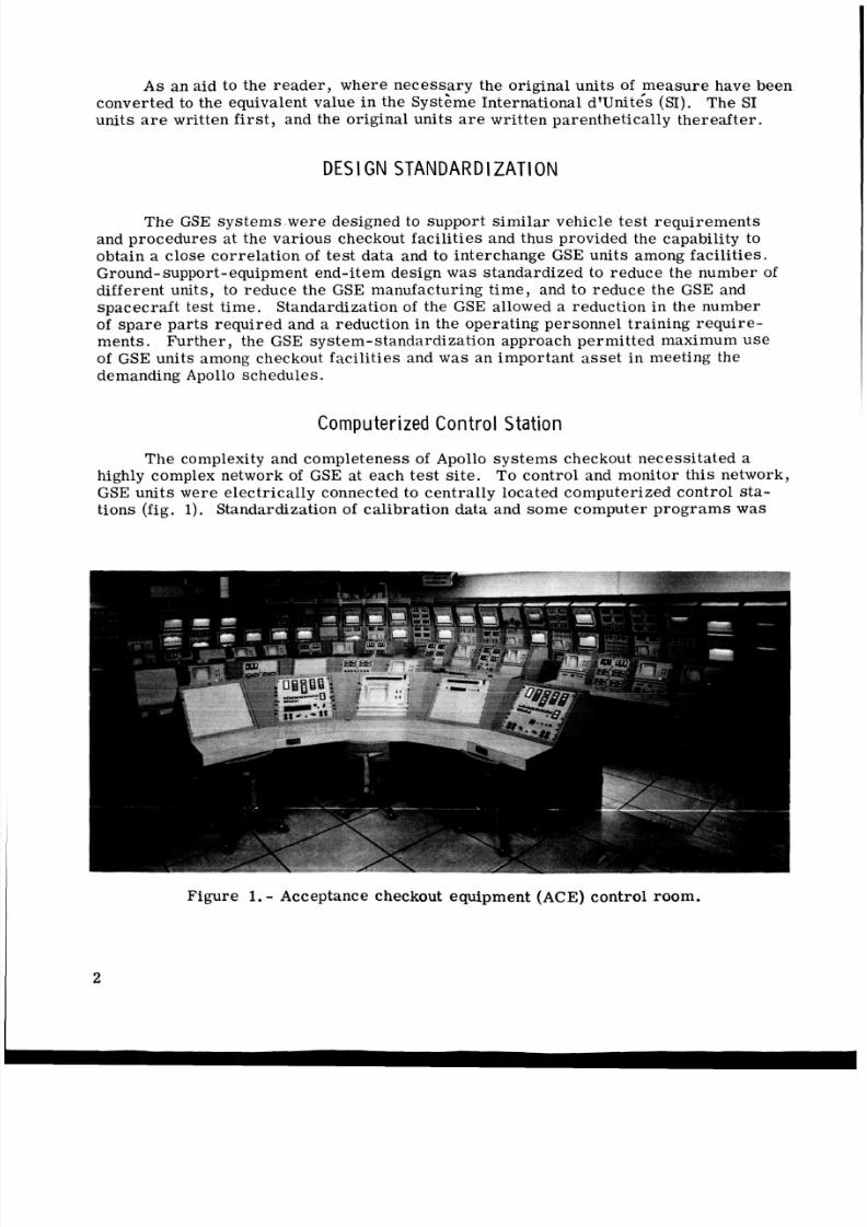
C o m p u t e r i ze d C o n t r o l S t a t i o n
The complexity and complet eness of Apollo s ys te ms checkout neces sitat ed ahighly complex network of GSE at each te st site, To control and monitor this network,GSE units were electrically connected to centrally located computerized control sta-tions (fig. 1). Standardization of calibration data and some computer pr ogra ms was
Figure 1.- Acceptance checkout equipment (ACE) control room.
2
8/8/2019 Apollo Experience Report Ground-Support Equipment
http://slidepdf.com/reader/full/apollo-experience-report-ground-support-equipment 9/27
possible because the networks at the various test sit es were sim ila r. This standard-
ization, coupled with tes t requiremen ts and procedural simila rity, permitted a close
correl ation of te st data fr om the factory to the launch pad. Thus, the probability of
detection of any s pacec raft sys tem s degradation during preflight testing was enhanced.
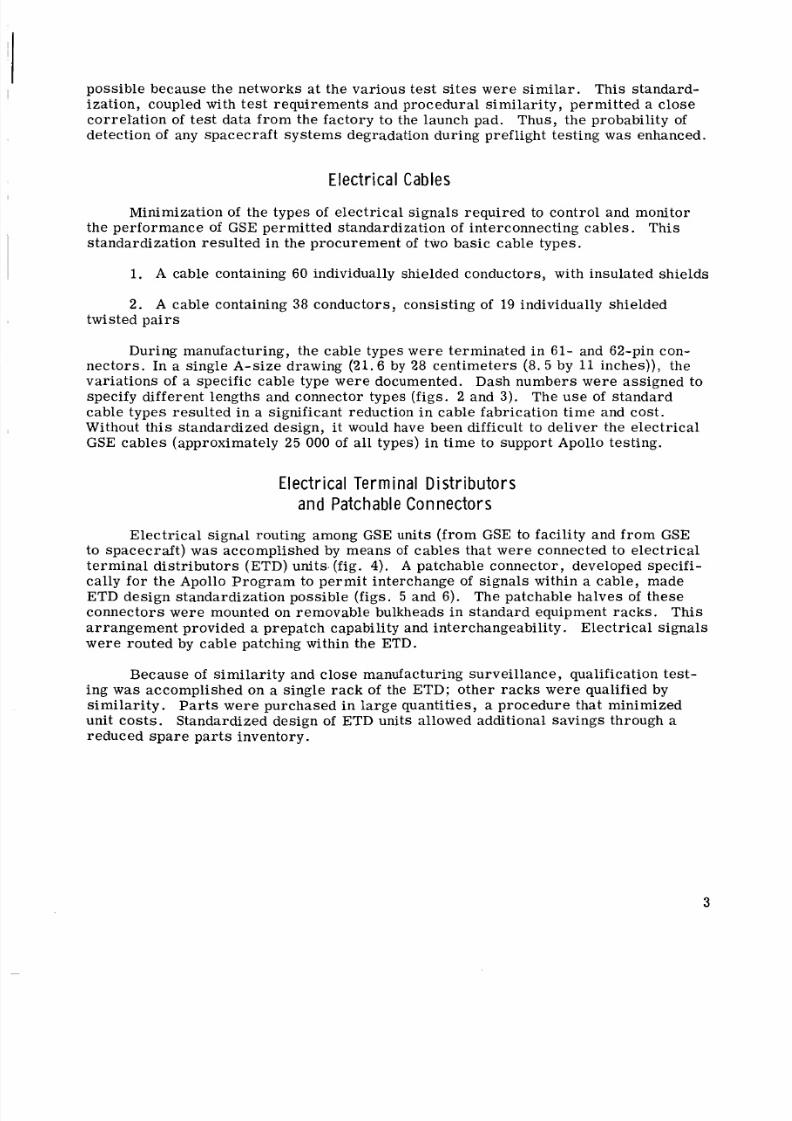
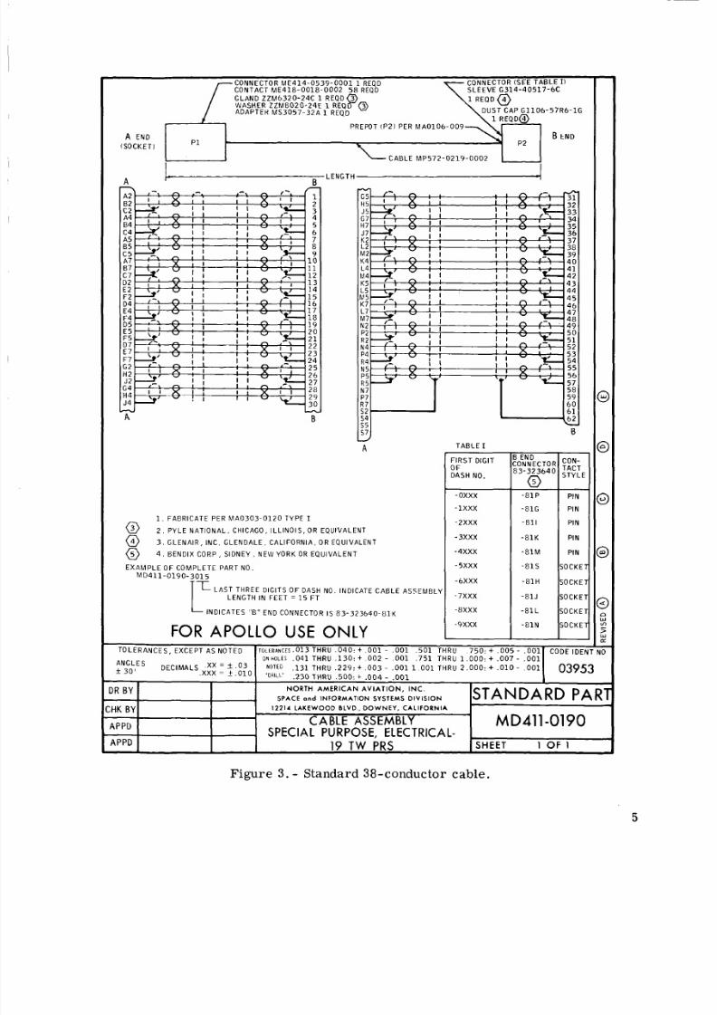
E e c tr a I CablesMinimization of the types of ele ctr ica l signa ls req uired to control and monitor
the per forman ce of GSE permit ted standardization of interconnecting cab les . This
standardization res ult ed in the procu rement of two basic ca ble types.
1. A cable containing 60 individually shielded conductors, with insulated sh ields
2. A cable containing 38 conductors, consisting of 19 individually shielded
twisted pair s
During manufacturing, the cable types were terminated in 61- and 62-pin con-
nectors. In a single A-size drawing (21.6 by 28 centimeters (8. 5 by 11 inches)), thevariations of a speci fic cable type were documented. Dash number s were assigned to
specify different lengths and connector types (figs. 2 and 3). The us e of stan dard
cable types resulted i n a significant reduction i n cable fabrication tim e and cost .
Without t his standardized design, it would have been difficult to deliver the ele ctr ica l
GSE cables (approximately 25 000 of a ll types) in time to support Apollo testing.
E l e c t ri c a l T e r m i n a l D i s t r i b u t o r s
and P a t ch a b le C o n n e c t o r s
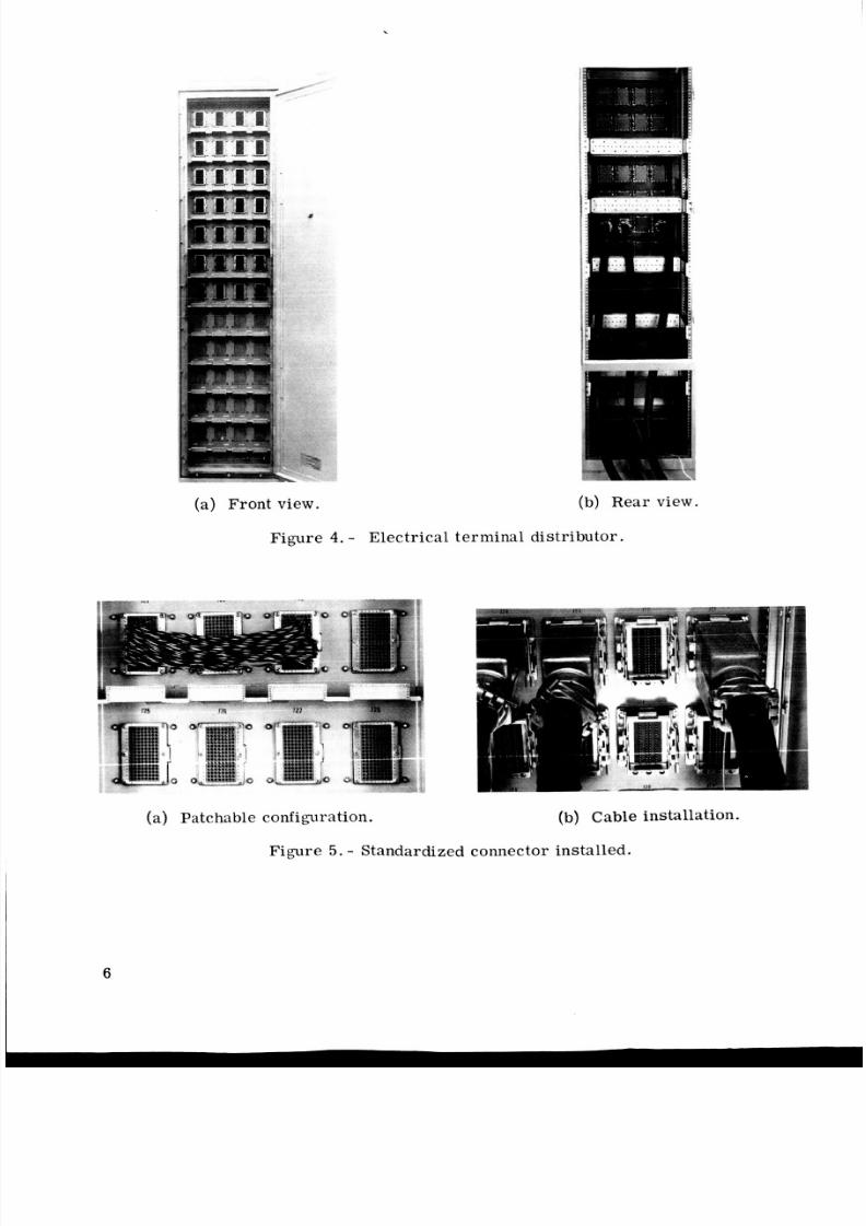
Electrical signal routing among GSE units (from GSE to facility and from GSE
to s pacecr aft) was accomplished by means of cab les that we re connected to ele ctr ica ltermin al distri butor s (ETD) units. (fig. 4 ) . A patchable connector, developed specifi-
cally fo r the Apollo Pro gr am to perm it interchang e of signa ls within a cable, made
ETD design standardization possible (figs. 5 and 6). The patchable halves of these
connec tors were mounted on removable bulkheads in standar d equipment rac ks. Thi s
arrang ement provided a prepatch capability and interchangeability. Ele ctr ica l signa ls
were routed by cable patching within the ETD.
Because of simila rity and close manufacturing surveillance, qualification test-
ing was accomplished on a single rack of the ETD; other ra ck s wer e qualified by
similar ity. Pa rt s were purchased in large quantities, a procedure that minimized
unit cost s. Standardized design of ETD units allowed additional savings through areduced sp ar e parts inventory.
3
8/8/2019 Apollo Experience Report Ground-Support Equipment
http://slidepdf.com/reader/full/apollo-experience-report-ground-support-equipment 10/27
4
CONNECTOR ME414-0539-0001 1 REQDCONTACT, ME418-0018-0002 6 1 REQDGLAND ZZM6320-22C 1 REQDW A S H E k , Z Z M 8 0 2 0 - 2 4 E , 1 REOD 8ADAPTER, MS3057-32A 1 REQD
CONNECTOk, (SEE TAB LE I)S LE EV E, ~ 6 1 0 0 4 - 1 5 R G 6 0 8 5 4 - 15 1 EQD(REMOVE GROMMET FOLLOWER, BEF ORE INS TAL LAT ION 'DUSTCAP, G317R246-1B 1 REQD
@
l Qr
A END P 1 . P 2 B END(SOCKET) <CABLE MP 57 2- 02 21 -0 00 1
1
I.c 7D 2E 2F 2D 4E 4F4D 5E 5F5
D 7E 7F7
G2H 2J 2G 4H 4J4
A8
CDEFGHJKL
MNPR
TUvwX
Y
b
der
I S
gC
-
wB
J
A
1. F A BR ICA T E PE R M A 0 3 0 3 - D l 2 0 T Y P E I .
2 . PYL E NATIONAL, CHICAGO, ILLINOI S, OR EQUI VAL ENT.3 . GLENAIR. INC., GLENDALE. CALIFORN IA, OR EQUIVALE NT)
EXAMPLE OF COMPLETE PART NO.M D 4 1 1 - 0 1 9 7 - 3 0 1 5
7- AST TH R EE DIGITS O F D A S H NO. INDICATE CABLEASSEMBLY LENGTH IN F E E 1 = 15 F IT
INDICATES "6 " END CONNECTOR I S M S 3 1 2 6 E 2 4 - 6 1 P Y
FOR APOLLO USE ONLY
T A B L E I
FIRST DIGITOFDASH NO.
-0xxx
-1xxx- 2 x x x
- 3 x x x
-4xxx
- 5 x x x
- 6 X X X
- 7xxx
-axxx
-YXXX
3 END:ONNECTORi n S 3 1 2 6 E 2 4
- 6 1 P
-61PW
- 6 1 P X
- 6 l P Y
- 6 1 P Z
-61s
-61SW
- 6 1 S X
- 6 1 S Y
- 6 1 5 2
OLERANCES, EXCEPT AS NOTED T O L E R A N C L S ,013 THRU , 0 4 0 :t 00 1 - ,001 , 5 0 1 TH Rl I , 7 5 0 : + . 0 0 5 - .001 CODE IDEN
O N H O L t S ,041THRU ,130: t 002 - ,001
, 230 THRU ,500: t .004 - ,001
, 7 5 1 T HR U 1.000: t.007- 001NGLES f 0' DECIMALS .XX = A . 0 3 N O T E D , 1 3 1 T H RU , 2 2 9 : + ,003 , 0 0 1 1.001 THRU 2 , 0 0 0 : t .010 - . 0 0 1 03953
) R BY
.XXX = t.010 'DRILL'
N O R T H A M E R IC A N A V I A T I O N , I N C . STANDARD PARPACE an d I N F O R M A T I O N SY S TE M S D I V I S I O N
1 2 2 1 4 L AKE WOO D I )L VD.. DOWNEY, C A L I F O R N I A;HK BY- MD411-0197SPECIAL PURPOSE, ELECTRICAL- ,
rPPD
\PPD 60 CONDUCTOR S H E E T 1 OF 1
Figure 2. - Standard 60-conductor cable.
8/8/2019 Apollo Experience Report Ground-Support Equipment
http://slidepdf.com/reader/full/apollo-experience-report-ground-support-equipment 11/27
CONNECTOR (SEE TAB LE I)S L EE V E 6 3 1 4 - 4 0 5 1 7 - 6 C
O U S T C A P G 1 1 0 6 - 5 7 R 6 - 1 G1 R E O O ~
CONNECTOR ME414-0539-0001 1 REQDC ON TA CT M E 4 1 8 - 0 0 1 8 - 0 0 0 2 5 8 R E Q O
GLAND ZZM6320-24C 1 REQD 3WASHER ZZM8020-24E 1 E Q p @AOAPTEK MS 3057-3 2A 1 REQD
xx * . O 3N b L t 5
* 3 0 ' x x x = _ + . 0 1 0---R B Y
:HK B Y
A P P D
A P P D,
- P R E W T tP 2 ) P ER M A 0 1 0 6 - 0 0 9 - \ 1
N O T E E
'ORILL.
, 1 3 1 T HR U ,2 2 9 : t 0 0 3 - , 0 0 1 1 00 1 THRU 2.000: + . 0 1 0 - 0 0 1
,230 THRU ,500 : + ,004 - , 0 0 1
N O R T H A M E R IC A N A V I A T I O N , I N C .
S P A C E o n d INFORMATION SYSTEMS DIVISION
12214 L A K E W O O D B L V D , D O W N E Y , C A L I F O R N I A
STANDARD PARI
CABLE ASSEMBLY MD411-0190
19 TW PRS SHEET 1 OF 1
SPECIAL PURPOSE, ELECTRICAL- ,
B t N 0P 1 P 2
A EN 0
(SOCKET
C A B L E M P 5 7 2 - 0 2 1 9 - 0 0 0 2
I IA k LENGTH -1
A B
L 4 4 1M4 4 2K5 4 3L5 44M5 4 5K7 4 6L7 47M 7 4 8N 7 A 9
1 12
BJ
A
1. FABRICATE PER MA03 03- 012 0 TYPE I
2. PYLE NATIONAL. CHICAGO, ILLINOIS, O R EQUIVALENT
3 . GLENAIR, INC. GLENDALE, CALIFORNIA, O R EQUIVALENT
4 . BENOIX CORP, SIDN EY, NEW YORK O R EQUIVALENT
@@@EXAMPLE OF COMPLETE PART NO.
M D 4 1 1 - 0 1 9 0 - 3 0 1 5
LAST THREE DIGITS OF DASH NO. INDICATE CABLE ASSEMBLLLENGTH IN FEET = 1 5 F T
INDICATES "6" EN0 CONNECTOR IS 8 3 - 3 2 3 6 4 0 - 8 1 K
FOR APOLLO USE ONLY
TABLE I
FIRST O I G I lOFDASH NO.
- 0 x x x
- l x x x
- 2 x x x
- 3 x x x
- 4 x x x
- 5 x x x
-6XXX
- 7 x x x
-8XXX
- 9 x x x
ONNECTOR: 3 - 3 2 3 6 4 0
'ON-
- 8 1 P I PIN
-81G
-811
- 8 1 K
PIN
PIN
PIN
TOLE RANC ES, EXCEPT AS NOTED T O L E R A N C E S . ~ ~ ~H R U .0 4 0 : t 0 0 1 - , 0 0 1 . 5 0 1 T HR U 7 5 0 : + , 0 0 5 - ,0 01 CODE IOEh
. - -. O N H O L E S , 0 4 1 THRU , 1 3 0 3 0 0 2 - , 0 0 1 , 7 5 1 T HRU 1 . 0 0 0 : + , 0 0 7 - , 0 0 1
Figure 3. - Standard 38-conductor cable.
5
8/8/2019 Apollo Experience Report Ground-Support Equipment
http://slidepdf.com/reader/full/apollo-experience-report-ground-support-equipment 12/27
.
r
(a) Fro nt view. (b ) Rea r view.
Figure 4. - Electrical terminal distributor.
(a) Patchable configuration. (b) Cable installation.
Figure 5. - Standardized connector installed.
6
8/8/2019 Apollo Experience Report Ground-Support Equipment
http://slidepdf.com/reader/full/apollo-experience-report-ground-support-equipment 13/27
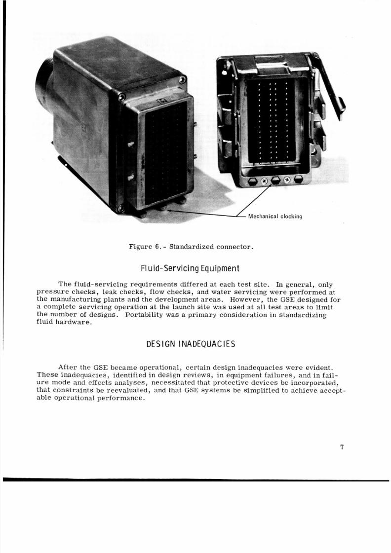
2.- echanical clocking
Figure 6. - Standardized connector.
FI u d- Servicing EquipmentThe fluid-servicing requirements differed a t each tes t si te. In general, only
pres sur e checks, leak checks, flow checks, and water servicing were performed atthe manufacturing p lants and the development areas. However, the GSE designed fora complete servici ng operation at the launch site was used at all test areas to limitthe number of designs. Portability wa s a prima ry consideration in standardizingfluid ha rdware.
DES GN I NADEQUACI ES
A f t e r the GSE became operational, certain design inadequacies were evident.The se inadequacies, identified in design reviews, in equipment fai lur es, and in fail-
u r e mode and effects analyses, necessitated that protective devices be incorporated,that con strai nts be reevaluated, and that GSE sys tems be simplified to achieve accept-able operational performance.
7
8/8/2019 Apollo Experience Report Ground-Support Equipment
http://slidepdf.com/reader/full/apollo-experience-report-ground-support-equipment 14/27
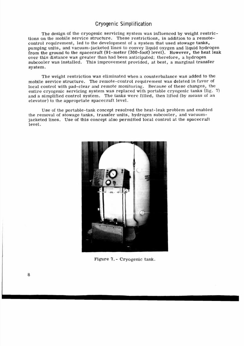
Cryogenic Simplification
The design Of the cryogenic servicing system wa s influenced by weight restric-tions on the mobile serv ice stru ctur e. These restri ctio ns, in addition to a remote-contro l requi rement , led to the development of a system that used stowage tanks,pumping units, and vacuum- jacketed l ines to convey liquid oxygen and liquid hydrogenfr om the ground to the spacecraft (91-meter (300-foot) level). However, the heat leak
over this distance w a s grea ter than had been anticipated; ther efor e, a hydrogensubcooler w a s installed. This improvement provided, at best, a marginal transfersystem.
The weight res tric tion w a s eliminated when a counterbalance w a s added to themobile service stru ctur e. The remote-control requirement was deleted in favor oflocal control with pad-cl ear and remo te monitoring. Because of these changes, theenti re cryogenic servicing system w a s replaced with portable cryogenic tanks (fig. 7)and a simplified control system . The tanks we re filled , then lifted (by means of a nelevator ) to the appropr iate s pace craf t level.
Use of the portable-tank concept resolved the heat-leak problem and enabled
the removal of stowage tanks, tra nsf er uni ts, hydrogen subcooler , and vacuum-jacketed lines. Use of this concept al so permit ted local control at the spacecra ftlevel.
Figure 7.- Cryogenic tank.
8/8/2019 Apollo Experience Report Ground-Support Equipment
http://slidepdf.com/reader/full/apollo-experience-report-ground-support-equipment 15/27
Pro tec t i ve Dev i ces
Protec tive d evice s wer e incorporated after initial production of the units . For
example, switchguards we re installed on approximately 250 units to prevent inadvert-
ent switch actuations, and shatterproof len ses were installed to protect personnel fr om
flying gla ss and to protect readout devices from damage.
C h e c k o u t R e q u i r e m e n t s
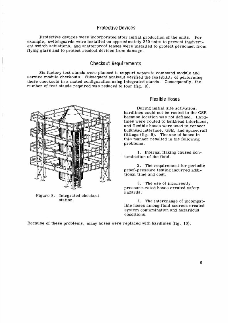
Six factor y tes t stands we re planned to support s epa rat e command module and
se rvi ce module checkouts. Subsequent analysis verified the feasibility of performing
these checkouts in a mated configuration using integrated stand s. Consequently, the
number of te st stands req uired wa s reduced to four (fig. 8 ) .
Flex ib le Hoses
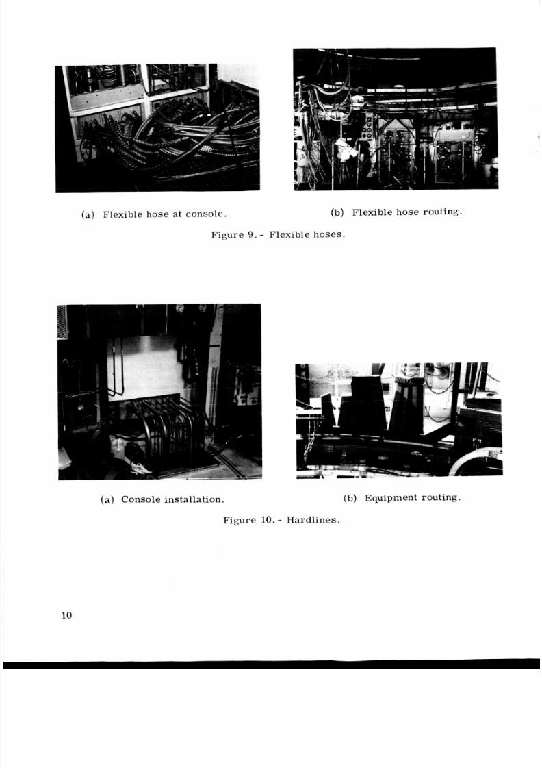
During initial site activation,hardlines could not be routed to the GSEbecause location was not defined. Hard-
lines we re routed to bulkhead interfac es,
and flexible hose s were used to connect
bulkhead interface, GSE, and spacecraft
fittings (fig. 9). The us e of hose s in
this manner result ed in the following
problems.
1. Internal flaking caused con-
tamination of the fluid.
2 . The requirement for periodic
proof-pressure testing incurre d addi-
tional time and cost.
3 . The u se of i ncorre ctly
pressur e-rated hoses created safety
hazards.
station. 4. The interchange of incompat-
ible hoses among fluid sourc es cr eated
sys tem contamination and hazardous
conditions.
Figure 8. - Integrated checkout
Becaus e of these problem s, many hoses were replaced with hardli nes (fig. lo) .
9
8/8/2019 Apollo Experience Report Ground-Support Equipment
http://slidepdf.com/reader/full/apollo-experience-report-ground-support-equipment 16/27
(a) Flexible hose at console.
Figure 9..
(b) Flexible hose routing.
F1 xibl e hose s .
(a) Console installation.
Figure 10. - Hardlines.
(b) Equipment routing.
10
8/8/2019 Apollo Experience Report Ground-Support Equipment
http://slidepdf.com/reader/full/apollo-experience-report-ground-support-equipment 17/27
E l e c t r ic a l C o n n e c t o r s
Many testing hour s wer e lost because of impr oper p roce dure s in the mating and
demating of elect ric al connectors. To avoid this prob lem, a mate and demate connec-
tor checklist was implemented. Connections require d for specific test s wer e con-
trolled by installing plastic connector locks that were verified by quality control.
E l e c t r i c a l P r o b l e m s
A spacecraf t system/GSE asse ssme nt revealed that cur ren t and voltage levels
in exc ess of spac ecra ft specification limit s could re sult i f elec tric al GSE was improp-
erly adjusted or operated o r i f a GSE cont rol component fai led. Res ult s of analys is
indicated that such a condition would overstress spacecraft components and could go
undetected in subsequent test s. Voltage- and current- limiting de vices (such as c i r -
cuit breakers, fuses, diodes, and resis tors ) were added to co rr ec t thi s condition.
Over pressu e P r ob le m s
Many GSE relief valves were not s ized properly to c a r ry the quantity of fluid
that would be avai lable i f an upstream regulator failed. A regulato r fa ilur e would
allow pressures at the spacecraft interface to exceed specification limi ts. Ther efor e,
properly sized relief valves wer e added.
GROUND POWER SYSTEM
During the conceptual stages of the Apollo GSE design, di re ct current (dc) was
selected a s the type of pr im ar y power sourc e to be used f or cont rol and monitor func-
tions. Thi s selection was influenced by three important facto rs that greatly simpli-
fie d the detailed design of the GSE end item s. Fi rs t, many commercially available
elec tric al components wer e designed to use 28 volts dc. Second, dc control signals
did not req ui re the complex routing, grounding, and shielding techniques that were
required by alternating-current (ac) control signals. Thir d, and most important , the
GSE dc control system w a s more compatible with the spacec raft because the prima ry
Spacecraft power sour ce was also dc.
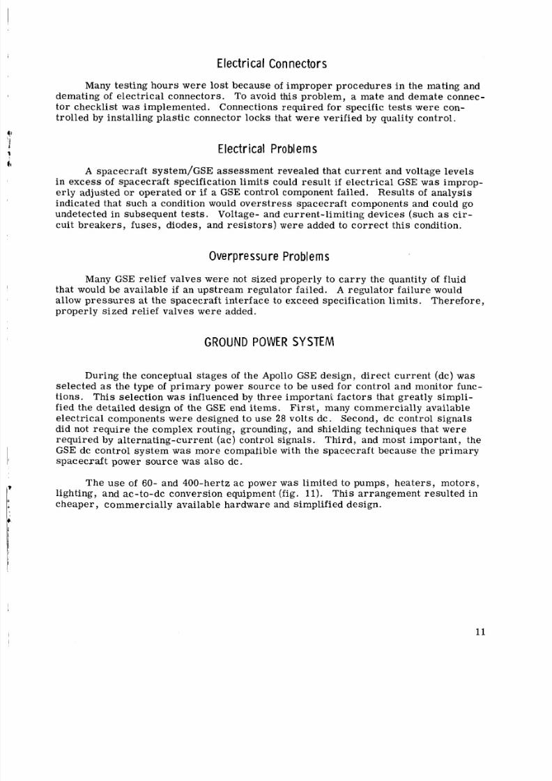
The u se of 60- and 400-hertz ac power w a s limited to pumps, heaters, motors,
lighting, and ac-to-dc conversion equipment (fig. 11). This arrangement resulted in
cheaper , commerci ally available hardware and simplified design.
11
8/8/2019 Apollo Experience Report Ground-Support Equipment
http://slidepdf.com/reader/full/apollo-experience-report-ground-support-equipment 18/27
. Figure 11. - Alternating-current to direct-current
converter.
D i r e c t - C u r r e n t G r o u n d P o w er S y st em
"I
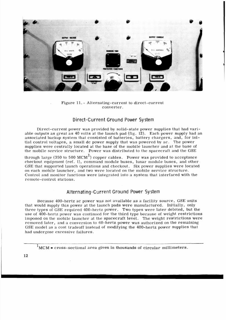
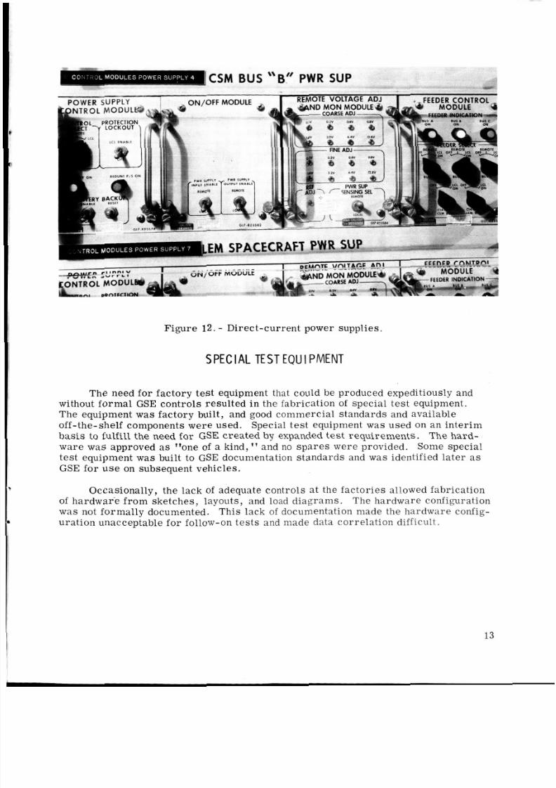
Direct-current power was provided by solid-state power supplies that had vari-able outputs as great as 40 volts a t the launch pad (fig. 12). Each power supply had anassociated backup system that consisted of ba tte rie s, battery ch arg er s, and, f or ini-tial control voltages, a sma ll dc power supply that was powered by a c. The powersupplies were cent rally located at the base of the mobile launcher and a t the base ofthe mobile service struct ure . Power was distributed to the spacecraf t and the GSE
1
through large ( 3 5 0 to 500 MCM ) copper cables. Power was provided to acceptancecheckout equipment (ref. l ) , command module buses, lunar module buses, and otherGSE that supported launch operations and checkout. Six power supplie s wer e locatedon each mobile launcher, and two were located on the mobile service structure.Control and monitor functions we re integrated into a syst em that interfaced with theremote-control stations.
A l t e r n a t i n g - C u r r e n t G r o u n d P ow e r S y st em
Because 400-hertz ac power was not available as a facility source, GSE unitsthat would supply this power at the launch pads wer e manufactured. Initially, onlythree types of GSE requir ed 400-hertz power. Two types wer e lat er deleted, but theus e of 400-hertz power was continued for the t hird type because of weight res tri cti onsimposed on the mobile launcher at the spacecr aft level. The weight restri cti ons wereremoved later, and a conversion to 60-hertz power was authorized on the remainingGSE model a s a cost tradeoff instead of modifying the 400-hertz power supplies thathad undergone excessive failures.
'MCM = cross-sectional area given in thousands of circula r mill imeters.
12
8/8/2019 Apollo Experience Report Ground-Support Equipment
http://slidepdf.com/reader/full/apollo-experience-report-ground-support-equipment 19/27
\\ It
CSM BUS B P W R !
D A W E D C i i D D l Y r REMOTE VOLTAGE ADJ I
t.
-LEMm . * . .. SPACECRA
Figure 12 . - Direct-current power supplies.
SPECIAL TESTEQUIPMENT
The need for factory test equipment that could be produced expeditiously andwithout for mal GSE contro ls resu lted i n the fabrication of special te st equipment.The equipment was facto ry built, and good commerci al standards and availableoff-the-shelf components wer e used. Special test equipment was used on an interi mbas is to fulfill the need fo r GSE created by expanded te st requirements. The hard-ware w as approved as "one of a kind, '' and no sp ar es were provided. Some specialtest equipment was built to GSE documentation standards and was identified later asGSE for u s e on subsequent vehicles.
Occasionally, the lack of adequate controls a t the fact ori es allowed fabricationof hardwar e fro m sketches, layouts, and load diagrams. The hardware configurationwas not forma lly documented. This lack of documentation made the hardware config-
ura tion unacceptable fo r follow-on te st s and made data corr elation difficult.
13
8/8/2019 Apollo Experience Report Ground-Support Equipment
http://slidepdf.com/reader/full/apollo-experience-report-ground-support-equipment 20/27
CLEA NLINES S AND EN Vl RONMENTAL CONTROL
To achieve reliable perf orm ance of the Apollo sy ste m, all operations that involvedvehic le buildup, testing, and shipping had to be perfor med in a cleanroom environment.The GSE fluid- sys tems cleanliness was controlled by a specification that defined allow-able contamination levels.
E n v i r o n m e n t a l l y C o n t r o l l e d A re a s
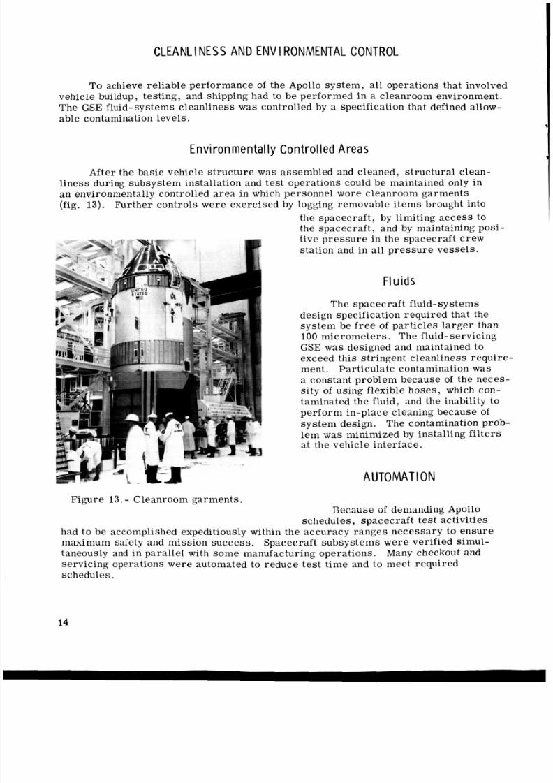
After the basic vehicle str uc tur e was assem bled and cleaned, struct ural clean-liness during subsystem installation and test operations could be maintained only inan environmentally controlled area in which personnel wore cleanroom g arm ents(fig. 13). Further controls wer e exercis ed by logging removable items brought into
the spacecraft, by limiting access tothe spacecraft, and by maintaining posi -tive pr es su re in the spacecraft crewstation and in all pressure vessels .
FIu i d s
The spacecraft fluid-systemsdesign specification required that thesystem be free of particles larger than100 mic rom ete rs . The fluid-servicingGSE w a s designed and maintained toexceed this stringent cleanliness require-ment. Partic ulate contamination wasa constant probl em because of the neces-
sit y of using flexible ho se s, which con-taminated the fluid, and the inability tope rfo rm in-place cleaning because ofsy st em design. The contamination prob-le m was minimized by installing fil te rsat the vehicle interface.
AUT OMAT ION
Figure 13. - Cleanroom garments.13ecause of de iianding Apollo
schedules, spacecraft test activitieshad to be accomplished expeditiously within the a ccur acy ra nge s nec es sar y to ens uremaximum safety and mission succ ess , Spacecraft subsyst ems wer e verified simul-taneously and i n parall el with some manufacturing opera tions. Many checkout andservic ing operations were automated to reduce test time and to meet requiredschedules.
14
8/8/2019 Apollo Experience Report Ground-Support Equipment
http://slidepdf.com/reader/full/apollo-experience-report-ground-support-equipment 21/27
Automated Checkout
The electrical checkout and fluid- serv icing functions f m the Apollo spacecr aftsubsystems were commanded and monitored from a remotely located computerizedcontro l roo m (fig. 1). Within this control room, computer ro utines we re used to applyspacecraft subsystem test stimuli. Related spacec raft resp onse s wer e displayed onsubsyste m consoles and monitored for out-of-tolerance conditions. Subroutines we re
use d fo r fault isolation tes ts during troubleshooting operations. The automation offactory test and launch control sequences was instrumental in achieving a well coor-dinated and expeditious spacecraft checkout and launch operation (ref. 1).
Automated Servic ing
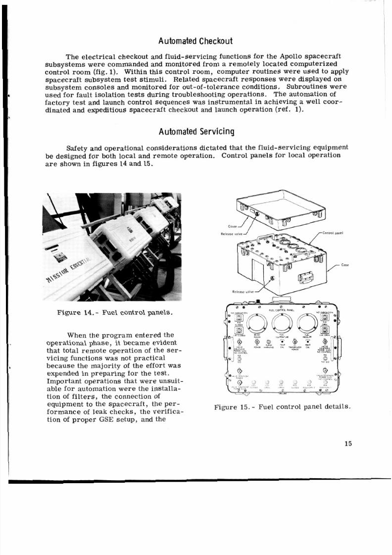
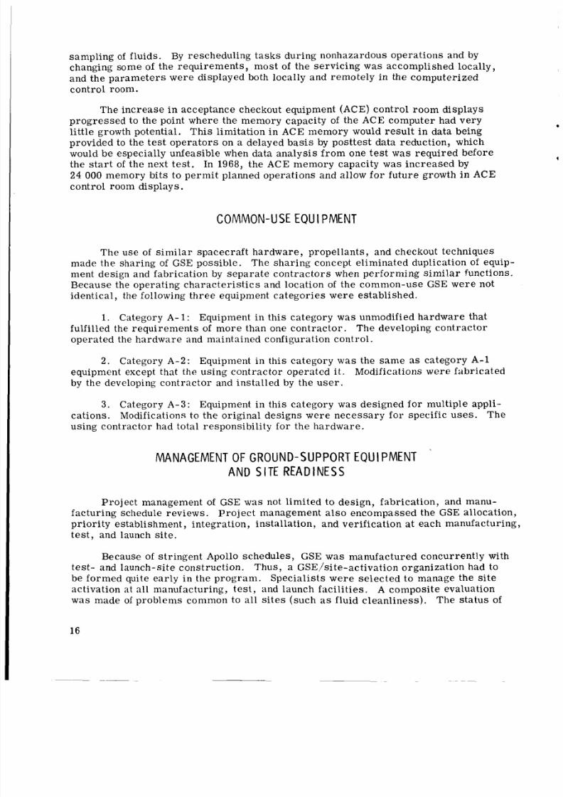
Safety and operational considerations dictated t hat the fluid- servicin g equipmentbe designed for both local and rem ote operation. Control panels for local operationare shown in fig ure s 14 and 15.
Figure 14. - Fuel control panels.
When the prog ram entered theoperational phase, it became evidentthat total remote operation of the ser-vicing functions was not practicalbec ause the majority of the effort was
expended in prep arin g for the test.Important operations that were unsuit-able fo r automation wer e the installa-tion of filters, the connection ofequipment to the spacecraft, the pe r-fo rm an ce of leak checks, the verifica-tion of proper GSE setup, and the
Figure 15. - Fuel control panel details.
15
8/8/2019 Apollo Experience Report Ground-Support Equipment
http://slidepdf.com/reader/full/apollo-experience-report-ground-support-equipment 22/27
sampling of fluids. By rescheduling ta sk s during nonhazardous operations and by
changing some of the requi rem ent s, mos t of the serv icing w a s accomplished locally,
and the parameters were displayed both locally and remotely in the computerized
control room.
The increas e i n acceptance checkout equipment (ACE) control r oom displays
pro gre sse d to the point where the memory capacity of the ACE computer had very
little growth potential. Thi s limitation in ACE memory would result i n data beingprovided to the test o pera tors on a delayed basis by posttest data reduction, which
would be especially unfeasible when data analysis from one test was required before
the st a r t of the next test. In 1968, the ACE memory capacity was inc rea sed by
24 000 memory bi ts to per mit planned operations and allow fo r future growth in ACE
control room displays.
COMMON-USE EQUl PMENT
The use of s im ila r spacecraft hardware , propellants, and checkout techniques
made the sha ring of GSE poss ible. The shar ing concept eliminated duplication of equip-ment design and fabrication by sepa rat e cont rac tor s when performin g sim ila r functions.
Because the operating cha rac ter ist ics and location of the common-use GSE were not
identical, t h e following three equipment categories were established.
1. Category A- 1 : Equipment in this category was unmodified hardware that
The developing cont ract orulfilled the requir emen ts of mor e than one contr actor .
operated the hardware and maintained configuration control.
2. Category A- 2 : Equipment in this category w a s the same as category A-1
equipment except that the using contr acto r operated i t.
by the developing cont racto r and installed by the us e r .
Modifications were fabricated
3.
cations.
using contractor had total responsibility for the hardware.
Category A-3: Equipment in this category was designed for multiple appli-
Modifications to the original designs were necessary for specific use s. The
MANAGEMENT OF GROUND-SUPPORT EQUIPMENT
AND SITE READINESS
Projec t management of GSE w a s not limited to design, fabrication, and manu-
facturing schedule reviews. Proj ec t management al so encompassed the GSE allocation,
priority establishment, integration, installation, and verification a t each manufacturing,
test, and launch site.
Because of stringent Apollo schedules, GSE was manufac tured concurrently with
test- and launch-site construction. Thus, a GSE/site-activation organization had to
be formed quite early in the prog ram. Specialists were s elect ed to manage the site
activation at all manufacturing, test, and launch facilities. A composite evaluation
was made of problems common to al l si te s (such as fluid cleanliness ). The status of
16
8/8/2019 Apollo Experience Report Ground-Support Equipment
http://slidepdf.com/reader/full/apollo-experience-report-ground-support-equipment 23/27
site readines s was a ss es se d by the NASA Lyndon B. Johnson Space Center (JSC)
(for merly the Manned Spacecraft Center (MSC)) i n monthly management reviewmeetings . When launch, vehicle , and tes t schedules changed, specific "need dates"
for GSE end it ems changed. These changes were reflected in the GSE production
plans and delivery schedules.
After initial s it e activation, sit e readiness for follow-on vehicles was determinedin an MSC and contractor review meeting conducted just before vehicle ar riv al for tes t
o r launch. This effort included a physical inspection of the s i te s and associated GSE.
A l l pertinent documentation, such as modification-installation stat us repor ts, open
engineering or de rs , quality and reliability control rec ord s, and interfac e control docu-
ment revisions, was reviewed in detail for open work,
M A 1NTENANCE AND OVERH AUL
Readiness of GSE was ensured by periodic calib rati on, overhaul , o r component
replacement. Overhaul candidates were primaril y i n the field of serv icin g equipment.
In the Apollo Progr am, serv icin g equipment had backup or redundant units that enabled
the perf ormance of o rde rly, timely overhauls with no launch cons traints.
Contracto r proposals fo r GSE overhauls were based on usage, age, o r failure
history. Thes e proposals were evaluated to determine the extent of overhaul. The
following considerations were included.
1. Use and environment of equipment
2. Expense of overhau l compared with expense of end-item replacement
3 . Availability of backup unit s to support pr im e uni ts
4. Availability of spares
5 . Review of the fa ilu re history
6 . Periodic repl acement of components already authorized in age/life component-
replaceme nt cri ter ia and in routine preventive maintenance schedules
RECOMMENDATIONS AND CONCLUSIONS
Recommenda t ion s
The following mate rial is presented primarily as recommendations for use in
future programs.
Design standardization. - Design standardization encompassed the use of stand-
a r d cables and patchable connectors that provided interchangeability and vers atil ity
among the ground-support-equipment units so that vehicle requirem ent changes could
17
8/8/2019 Apollo Experience Report Ground-Support Equipment
http://slidepdf.com/reader/full/apollo-experience-report-ground-support-equipment 24/27
be accomplished. Standardization of calibration data and som e computer pro gr am s
permitted a close co rrelation of tes t data fro m the facto ry to the launch pad.
Ground- support equipment was standardized to reduce the number of diff eren t units ,
to reduce the ground- support-equipment manufacturing tim e, and to reduce the
ground-support-equipment and spacecraft test time. Portability was a prima ry con-
sideration when fluid-servicing and test h ardware wer e standardized.
Design inadequacies. - Design inadequacies may be limited i f the most seve rerequirement is selected a s a design base. This s election would have the net effect of
limiting the number of design s, reducing spa re s, providing for interchange of hard-
ware between sites, limiting the total end items, and developing standard operating
techniques.
The use of flexible hoses as permanent installations should be avoided. How-
ev er , hoses a r e valuable for temporar y connections and for us e where cleanliness isnot a prime consideration.
Controls should be instituted for mating o r demating electr ical connectors.
Proper connections can be maintained i f destroy-to-remove plastic connector locks
are used. Another considera tion is an electrical series circuit that is routed throughall required connections and illuminates an indicator light.
On variable electr ica l power supplies, devic es should be provided to limit output
to the allowable system voltages or currents (or both). Groundsu ppor t equipment
should be designed for maintainability and fo r e as e of component replacement.
Capacity requir emen ts should be evaluated, and allowance should be made fo r
growth or expansion of sy ste m requ ireme nts. This consideration should be refl ected
in design standards applicable to new procurements.
Safety devices, such a s switchguards and safety glass on me ter s and gages,
should be incorporated into the original design. These device s could be incorporated
initially at a fraction of the cost for lat er addition. Periodic syste m analysis should
be performed on each major ground-support-equipment sys tem to ens ure that all pro-
tective devices a r e properly sized to protect the sp acec raft.
Ground power system. - The use of 28-volt di rec t-c urr ent power f o r ground
instrumentation and control is a good design approach . The power distr ibuti on
sou rce can be simplified by routing 60-hertz power to eac h usage area and then con-
verting it to dire ct curren t. Facility-supplied power require ments should be defined
early to establish the input-power design approach for ground-support equipment.
When 400-hertz power is required, it should be supplied fr om a facility s ystem .
The distribution system should be the same as that recommende d in routing 60-hertz
power.
Special test equipment. - Two cla ss es of special t es t equipment should be estab-
lished.
o r provides power, instrumentation, and servici ng functions.
requ ire formal configuration control. Cla ss 2 te st equipment should consist Of all
Class 1 should consist of equipment that inte rfac es directly with the spa cecr aft
Class 1 equipment should
18
8/8/2019 Apollo Experience Report Ground-Support Equipment
http://slidepdf.com/reader/full/apollo-experience-report-ground-support-equipment 25/27
other equipment (such as diagnostic test tools, special manufacturing devices, and
workstends). Class 2 equipment would r equ ire minimum configuration control at the
using si te; changes could be authorized by the resident manager.
Cleanliness and environmental control. - The vehicle cleanliness req uirem ents
should be established and thoroughly justified early i n the design phase because ground-
support-equipment costs inc rea se geometrically as cleanliness requirements becomemore stringent. During a ground-support-equipment syst em buildup, accep table
cleanliness must be verified as each component is installed. The final fluid sampl e
must be taken at the ground-support-equipment/vehicle nterface. A certified, cleanfilter should then be installed downstream of the l as t sample point before serv icing.
This insta llation eliminated the need for numerous expensive quick-disconnect fittings
used solely for sampling.
Hardware that ha s environmental requirements should be cleaned to an estab-
lished level early in it s construction, and this cleanliness should be maintained until
completion. Personnel should be given cleanliness instruction, and the required
cleanliness levels should be posted. Assembly areas should be designed and built
as specified’clean areas during initial construction.
Automation. - Decisions to determine the ground sys tem s to be automated. must
be based on a comprehens ive review of projected pro gra m miles tones . Automation
is recommended when extensive and complex tes t and launch operations, such .as those
encountered during the Apollo Pr og ra m, must be accomplished within a limited time
f ra me ; however, the costs of automation must be carefully weighed against those
requi red to pe rfor m relatively simple mechanical task s manually (such as costs asso-
ciated with Apollo fluid se rvic ing).
Common-use equipment. - The common-use concept should be considered fo r
projects that involve more than one contractor when identical or simila r requirements
exist . Contractor capabilities must be evaluated to selec t a hardware developer thatis bes t suited to provide specific ite ms of common-use equipment.
should include manpower loading, manufacturing capabilities, procurem ent proc edu res ,
and scheduled work-load considerations.
This evaluation
Management of ground-support equipment and site readiness. - Ground- support
equipment site- activation schedules must be coordinated with manufacturing and
cons truct ion activ ities and alined with expected facility-occupancy dates . An automatic
schedule-adjustment procedure should be available to compensate for vehicle schedule
changes,
requirements (such as size, access, lighting, ventilation, air conditioning, and power
sour ces) keep pace with tes t-a rti cle and checkout-requirement changes. Basic facilityint erf ace definitions should be provided early in the progr am. Adherence to interface
contr ol documents should be enforced rigidly.
Periodic facility technical evaluations should be conducted to ensure that basic
Vehicle checkout requi rem ent s should be integrated with facility and ground-
support-equipment support requirements to optimize checkout flow, to reduce total
time , and to minimize equipment requirements. Vehicle/ground- support- equipment
integrated schematics should be required for use in troubleshooting and normal test
operations. These documents must be updated regularly.
19
8/8/2019 Apollo Experience Report Ground-Support Equipment
http://slidepdf.com/reader/full/apollo-experience-report-ground-support-equipment 26/27
Maintenance and overhaul. - Preventive maintenance should be performed on aperiodic basis. A l l contra ctors and vendors should be required to deliver preventive
maintenance procedures and age/life component-replacement data with the end ite ms .
Initial procurement of these data is more economical than obtaining them la te r. When
possi ble, overhauls should be perfo rmed in conjunction with ma jor modifications.
Conclusions
Overa ll, the Apollo ground-support equipment perfo rmed satisf actor ily.
Although problems were encountered in ground-support-equipment operation because
of design inadequacies, mat er ia l and equipment incompatibil ities, or manufacturing
flaws, no major personnel injuries o r test/launch delays were attributed to the
ground- support equipment during the 8 ye ar s of Apollo Pr og ra m support.
Lyndon B. Johnson Space Cente r
National Aeronautics and Space AdministrationHouston, Texas, September 25, 1974
9 14- 0-00- 0- 2
REFERENCE
1. Burtzlaff, I . J . : Apollo Experience Report - Acceptance Checkout Equipment
for the Apollo Spacecraf t. NASA TN D-6736 , 1972.
20 NASA-Langley, 1915 s-415
8/8/2019 Apollo Experience Report Ground-Support Equipment
http://slidepdf.com/reader/full/apollo-experience-report-ground-support-equipment 27/27
NATIONAL AERONAUTICS AN D SPACE ADMINISTRATION
WASHINGTON, D.C. 20546
OFFICIAL BUSINESS
C r N A L T v COR PRIVATE UOE ssoo SPECIAL FOURTH-CLASS RATE
BOOK
P O S T A G E A N D F E E S P A I D
N A T I O N A L A E R O N A U TI C S A N DS P A C E A D M I N I S T R A T I O N
45 1
POBTYdsTIR :If Undeliverable (Sectlon 168Portal Mnnunl) DoNot Return
‘T he aeronautical and space activities of the United States shall beconducted so as to contn’bute , . . o the expansion of human knowl-edge of phenomena in the atmosphere and space. The Administrationshall eovide fo r the widest practicable and a p p r o e e dissemiffationof inf om ati on concerning its activities m d the results thereof.”
-NATIONAL AERONAUTICSND SPACE A m OF 1958
NASA SCIENTIFIC AND TECHNICAL PUBLICATIONS
TECHNICAL REPORTS: Scientific and
technical information considered important,
complete, and a lasting contribution to existing
knowledge.
TECHNICAL TRANSLATIONS: Information
published in a foreign language considered
to merit NASA distribution in English.
TECHNICAL NOTES: Information less broadin scope but nevertheless of importance as acontribution to existing knowledge.
TECHNICAL MEMORANDUMS:Information receiving limited distribution
because of preliminary data, security classifica-tion, or other reasons. Also includes conference
proceedings with either limited or unlimited
distribution.
CONTRACTOR REPORTS: Scientific and
technical information generated under a NASA
contract or grant and considered an important
contribution to existing knowledge.
SPECIAL PUBLICATIONS: Informationderived from or of value to NASA activities.Publications include final reports of major
projects, monographs, data compilations,handbooks, sourcebooks, and specialbibliographies.
TECHNOLOGY UTILIWTION
PUBLICATIONS: Information on technology
used by NASA that may be of particularinterest in commercial and other. non-aerospace
applications. Publications include Tech Briefs,Technology Utilization Reports andTechnology Surveys.
Details on the avai labi l i ty of these publications may be obtained from:
SCIENTIFIC AND TECHNICAL INFORMATION OFFICE
N A T I O N A L A E R O N A U T IC S A N D S P A C E A D M I N I S T R A T I O N