Corrections to UPL response, Ghunise Coaxum, UPL Bar Counsel

APL/UPL Series“Existing Design-In Only”
APL/
UPL
APL/UPL SeriesHydraulic Magnetic Circuit Protectors
INTRODUCTION
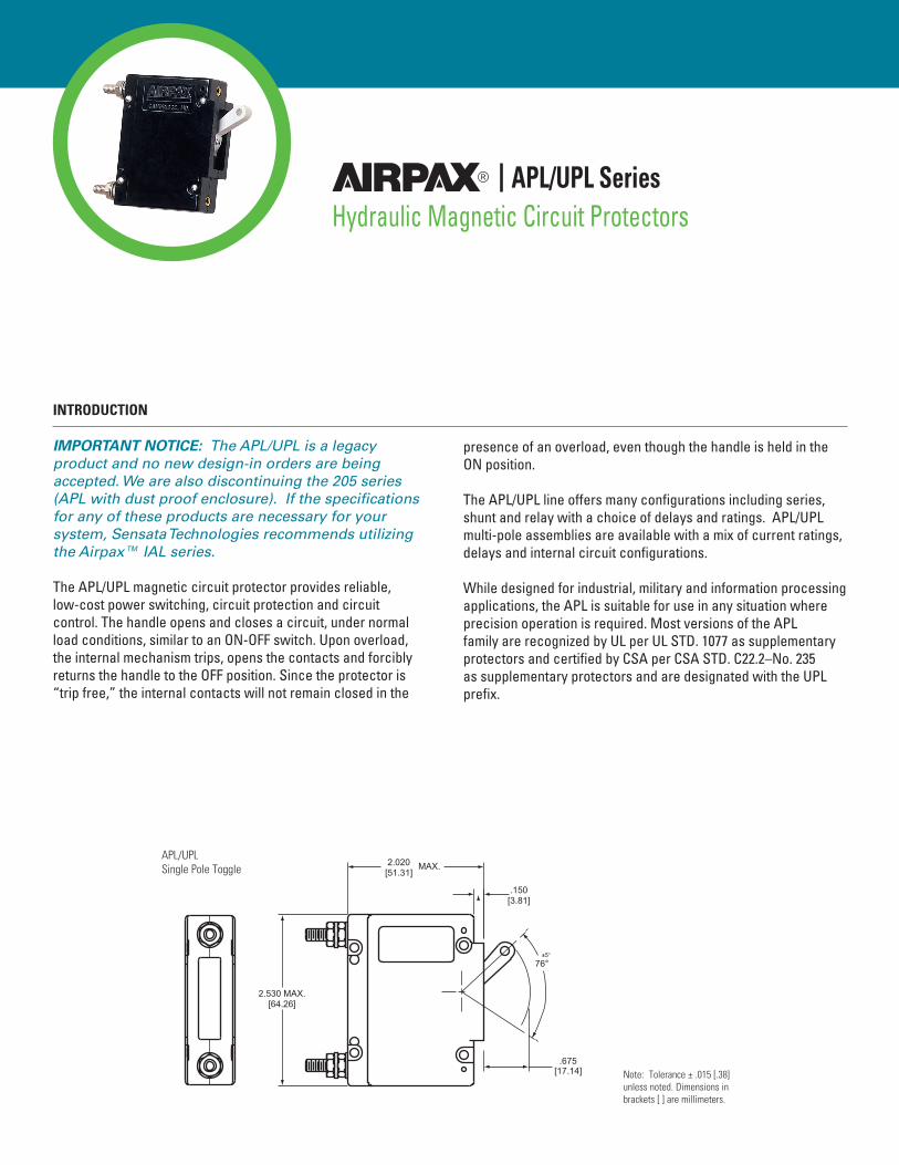
IMPORTANT NOTICE: The APL/UPL is a legacy product and no new design-in orders are being accepted. We are also discontinuing the 205 series (APL with dust proof enclosure). If the specifications for any of these products are necessary for your system, Sensata Technologies recommends utilizing the Airpax™ IAL series. The APL/UPL magnetic circuit protector provides reliable, low-cost power switching, circuit protection and circuit control. The handle opens and closes a circuit, under normal load conditions, similar to an ON-OFF switch. Upon overload, the internal mechanism trips, opens the contacts and forcibly returns the handle to the OFF position. Since the protector is “trip free,” the internal contacts will not remain closed in the
presence of an overload, even though the handle is held in the ON position.
The APL/UPL line offers many configurations including series, shunt and relay with a choice of delays and ratings. APL/UPL multi-pole assemblies are available with a mix of current ratings, delays and internal circuit configurations.
While designed for industrial, military and information processing applications, the APL is suitable for use in any situation where precision operation is required. Most versions of the APL family are recognized by UL per UL STD. 1077 as supplementary protectors and certified by CSA per CSA STD. C22.2–No. 235 as supplementary protectors and are designated with the UPL prefix.
.750 MAX.[19.05]
1.438[36.53]
.402[10.21]
.220[5.59]
6-32 THD. (M3 ISO. THD. OPTIONAL).187 [4.75] DEEP (TWO PLACES)
2.060 ± .010[52.32 ± 0.25] ONON
.150[3.81]
2.530 MAX.[64.26]
MAX.2.020[51.31]
.675[17.14] Note: Tolerance ± .015 [.38]
unless noted. Dimensions in brackets [ ] are millimeters.
APL/UPLSingle Pole Toggle

MULTI-POLE CIRCUIT PROTECTORS
Multi-pole protectors are combined in an assembly with the actuating handles linked and the trip mechanisms internally coupled. A fault in either protected circuit opens all poles simultaneously. Applications include use in two-phase circuits, single-phase three-wire systems or in two or more related but electrically isolated circuits. A mix of delays, ratings and configurations is possible, with the series type having any of the auxiliary switches listed. Combinations up to nine poles are available.
(SEE TABLE)
“A”
.75 ± .015[19.05 ± .38]
(TYP)
ONON
1.448[36.78]
.432[10.97]
2.280[57.91]
.750[19.05]
.432[10.97]
1.448[36.78]
2.060[52.32]
1.530[38.86]
Ø 4X .156[3.96]
.432[10.97]
1.448[36.78]
Ø 2X .156[3.96]
.755[19.18]
2.060[52.32]
.750[19.05]
.750[19.05]
2.060[52.32]
Ø 6X .156[3.96]
One Pole
Two Pole
Three Pole
Mounting Details
Panel Mounting Tolerances: ±.005 [.13] unless noted.
MULTI-POLE DIMENSIONS
2 pole “A” 1.515 [38.48] max
3 pole “A” 2.265 [57.53] max
4 pole “A” 3.015 [76.58] max
5 pole “A” 3.765 [95.63] max
6 pole “A” 4.515 [114.68] max
7 pole “A” 5.265 [133.73] max
8 pole “A” 6.015 [152.78] max
9 pole “A” 6.765 [171.83] max
Note: Dimension “A” varies with # of poles
APL/UPL Series
APL/
UPL

Series TripThe most popular configuration for magnetic protectors is the series trip where the sensing coil and contacts are in series with the load being protected. The handle position conveniently indicates circuit status. In addition to providing conventional over-current protection, it’s simultaneously used as an on-off switch.
Auxiliary Switch(Applies to Series Trip Only)This is furnished as an integral part of a series pole in single or multi-pole assemblies. Isolated electrically from the protector’s circuit, the switch works in unison with the power contacts and provides indication at a remote location of the protector’s on-off status. Auxiliary switch contacts actuate simultaneously with the main breaker contacts, and will open regardless of whether the breaker contacts are opened manually or electrically. For auxiliary switch ratings below 6Vac or 5Vdc, an auxiliary switch with gold contacts is available. Gold contacts are not recommended for load current above 100 milliamps. The contacts on our optional RS auxiliary switch will open only in the event of an electrical trip of the circuit breaker.
Shunt TripThe shunt trip is designed for controlling two separate loads with one assembly. The control is established by providing overload protection for the critical load. When the current through this load becomes excessive and reaches the trip point, the protector will open and remove power from both loads simultaneously. The total current rating of both loads must not exceed the maximum contact rating.
Relay TripThis permits the overload sensing coil to be placed in a circuit which is electrically isolated from the trip contacts. The coil may be actuated by sensors monitoring pressure, flow, temperature, speed, etc. Other typical applications include crowbar, interlock and emergency/rapid shutdown circuitry. Trip may be accomplished by voltage or current, which must be removed immediately upon tripping.
Dual CoilDual coil protectors provide remote shut down option and normal overcurrent protection in the confines of a single breaker pole. This construction saves space by eliminating the need for an additional pole for the voltage trip function.
Voltage TripSometimes called “dump circuits” or “panic trip circuits,” these units make it possible to open main power contacts with lower power inputs from one or more sources. This configuration is becoming increasingly more important for sensitive circuitry and denser packaging in automation systems. Available in series, shunt, relay or dual coil configurations.
APL/UPL CONFIGURATIONS

.187
[4.75]
.312
[7.92]
.187
[4.75]
.110
[2.79]
.295
[7.49]
REG 4
REC 4
REG 5
REC 5
RS
.281 ± .020
(7.14 ± 0.51)
1.940
[49.28]
BREAKER IN OFF POSITION
LINE
LOAD
NC
NO
C
( 50 AMP)
LOAD
LINE
(>50 AMP)
LOAD
LINE
.625 ± .031
(15.88 ± 0.79).281 ± .020
(7.14 ± 0.51)
.675 ± .050
(17.15 ± 1.27)
.280
(7.11)
1.940
(49.28)
1.290 ± .031
(32.77 ± 0.79)
.280 ± .031
(7.11 ± 0.79)
1.056 ± .031
(26.82 ± 0.79)
.648 ± .031
(16.46 ± 0.79)
.667 ± .020
[16.94 ± 0.51]
1.940
[49.28]
.281 ± .020
[7.14 ± 0.51]
.625 ± .031
[15.88 ± 0.79]
.667 ± .020
[16.94 ± 0.51]
1.275 ± .020
[32.38 ± 0.51]
1.940
[49.28]
.281 ± .020
[7.14 ± 0.51]
.625 ± .031
[15.88 ± 0.79]
TRIPSHUNT
TRIPNO VOLTAGE
COILDUAL
RATINGDUAL
TRIPRELAY
COILDUAL
LOAD
LINE
COIL.V
LINE
LOAD
LOAD
LOAD
LINE
LOAD
RELAY
RELAY
LINE
COIL
COIL LINE
LOAD
COIL
COIL
LINE
LOAD
Series Trip (See Note A)
Series Trip with Auxiliary Switch
Shunt, Relay and Dual Coil
Notes:Tolerance ± .015 [.38] unless noted. Dimensions in brackets [ ]are millimeters.A Terminal sizes: 10-32 THD (<50
AMP), ¼ -28 THD (>50 AMP) Metric Terminals (Optional),
M5 x 0.8 THD (<50 AMP).B Minimum useable thread length: 10-32 THD (.250 on breakers without terminal boards, .160 with terminal boards) ¼ -28 THD (.200).
APL/
UPL

Inrush Pulse Tolerance (typ)The following table provides a comparison of inrush pulse tolerance with and without the inertial delay feature for each of the 50/60Hz delays. Pulse tolerance is defined as a single pulse of half sine wave peak current amplitude of 8 milliseconds duration that will not trip the circuit breaker.
APL/UPL OPERATING CHARACTERISTICS
0.050 AMPS TO 50 AMPS - PERCENTAGE OF RATED CURRENT VS TRIP TIME IN SECONDS AT +25°CVoltage Delay 100% 125% (Note A) 150% 200% 400% 600% 800% 1000%
400 Hz
40 No Trip May trip .050 max. .040 max. .030 max. .025 max. .020 max. .018 max.
41 No Trip May trip .6 to 7 .2 to 2 .020 to .4 .007 to .25 .004 to .15 .004 to .040
42 No Trip May trip 5 to 70 2 to 22 .4 to 3.8 .015 to 2 .006 to .4 .004 to .1
43 No Trip May trip 40 to 280 9 to 70 1.3 to 15 .2 to 3.75 .023 to .6 .010 to .050
49 No Trip .180 max. .120 max. .050 max. .022 max. .017 max. .017 max. .017 max.
DC
50 No Trip May trip .032 max. .024 max. .020 max. .018 max. .016 max. .015 max.
51 No Trip .70 to 8 .40 to 4 .1 to 1.7 .02 to .30 .008 to .15 .004 to .06 .004 to .030
52 No Trip 8 to 100 3 to 30 .7 to 10 .18 to 2.5 .030 to 1 .004 to .5 .004 to .3
53 No Trip 80 to 600 30 to 300 10 to 100 1.5 to 15 .1 to 5 .008 to .3 .007 to .07
59 No Trip .100 max. .070 max. .032 max. .020 max. .016 max. .016 max. .016 max.
50/60 Hz
60 No Trip May trip .040 max. .035 max. .030 max. .025 max. .020 max. .018 max.
61 No Trip 1 to 18 .4 to 4 .180 to 1.8 .03 to .3 .009 to .15 .003 to .1 .003 to .08
62 No Trip 10 to 120 6 to 60 2 to 22 .2 to 2 .05 to .75 .015 to .15 .01 to .10
69 No Trip .180 max. .120 max. .050 max. .022 max. .017 max. .017 max. .017 max.
64 No Trip .7 to 10 .35 to 4.5 .15 to 1.5 .05 to .4 .025 to .3 .020 to .22 .015 to .15
65 No Trip 8 to 80 5.5 to 55 2 to 20 .5 to 5 .2 to 2 .06 to 1 .016 to .60
66 No Trip 50 to 700 30 to 350 10 to 100 1.5 to 20 .7 to 7 .1 to 3 .02 to 2
DC 50/60 Hz
70 No Trip May trip .040 max .035 max. .030 max. .025 max. .020 max. .018 max.
71 No Trip .35 to 14 .18 to 7.5 .10 to 3 .025 to 1 .015 to .30 .01 to .15 .007 to .10
72 No Trip 6.5 to 115 3 to 65 1.2 to 20 .08 to 3 .018 to 2.5 .015 to .80 .009 to .25
73 No Trip 45 to 700 25 to 400 10 to 175 .75 to 20 .12 to 4.5 .025 to 1 .01 to .25
ABOVE 50 AMPS - PERCENTAGE OF RATED CURRENT VS TRIP TIME IN SECONDS AT +25°CVoltage Delay 100% 125% (Note A) 150% 200% 400% 600% 800% 1000%
DC
50 No Trip May trip .100 max. .070 max. .032 max. .020 max. .020 max. .020 max.
51 No Trip .5 to 8 .3 to 4 .1 to 1.7 .02 to .3 .08 to .150 .004 to .060 .004 to .03
52 No Trip 2.5 to 100 1.5 to 40 .62 to 15 .15 to 2.5 .03 to 1 .004 to .5 .004 to .3
59 No Trip .100 max. .070 max. .032 max. .020 max. .016 max. .016 max. .016 max.
50/60 Hz
60 No Trip May trip .120 max. .050 max. .022 max. .017 max. .017 max. .017 max.
61 No Trip .7 to 18 .35 to 4 .130 to 1.8 .030 to .3 .008 to .150 .003 to .1 .003 to .08
62 No Trip 10 to 120 6 to 60 2 to 22 .2 to 2 .050 to .750 .007 to .15 .005 to .10
69 No Trip .180 max. .120 max. .050 max. .022 max. .017 max. .017 max. .017 max.
64 No Trip May trip .2 to 8 .15 to 7.6 .05 to .73 .025 to .3 .020 to .22 .015 to .15
65 No Trip May trip 3 to 55 2 to 20 .3 to 5 .13 to 2 .06 to 1 .016 to .60
Notes: All trip curves and trip currents are specified with the protector mounted in the normal vertical position at ambient temperature of +25° C. Protectors do not carry current prior to application of overload. A: 130% for delays 49, 135% for delays 71, 72 and 73
All trip curves and trip currents are specified with the breaker mounted in the normal vertical position at ambient temperature of +25°C. Protectors do not carry current prior to application of overload.

DELAY 60
900 1000
PERCENT OF RATED CURRENT
.001
10000
.01
100
1000
.1
1
10
TIM
E IN
SE
CO
ND
S
0 100125
150 200 300 400 500 600 700 800
DELAY 61
900 1000
PERCENT OF RATED CURRENT
.001
10000
.01
100
1000
.1
1
10
TIM
E IN
SE
CO
ND
S
0 100125
200 300 400 500 600 700 800
DELAY 62
900 1000
PERCENT OF RATED CURRENT
.001
10000
.01
100
1000
.1
1
10
TIM
E IN
SE
CO
ND
S
0 100125
150 200 300 400 500 600 700 800
DELAY 69
900 1000
PERCENT OF RATED CURRENT
.001
10000
.01
100
1000
.1
1
10
TIM
E IN
SE
CO
ND
S
0 100125
150 200 300 400 500 600 700 800
150
MAY
TRI
PM
AY T
RIP
MAY
TRI
PM
AY T
RIP
60Hz Delay Curves (typ)
A choice of delays are offered for 60Hz applications. Delays 60 and 69 are fast acting non-delayed tripping to protect sensitive electronic equipment (not recommended where known inrush exists). Delay 61 has a short delay for general purpose applications. Delay 62 is long enough to start certain types of motors and most transformers and capacitor loads. Delay 63 is an extra long delay primarily for special motor applications.
PULSE TOLERANCES
Delay Pulse Tolerance61, 62 12 times (approx.) rated current
61F, 62F 20 times (approx.) rated current
64, 65, 66 20 times (approx.) rated current
64F, 65F, 66F 35 times (approx.) rated current
Note: These limits do not apply to dual coil and tapped coil units
APL/
UPL

DELAY 64
900 1000
PERCENT OF RATED CURRENT
.001
10000
.01
100
1000
.1
1
10
TIM
E I
N S
EC
ON
DS
0 100125
150 200 300 400 500 600 700 800
DELAY 65
900 1000
PERCENT OF RATED CURRENT
.001
10000
.01
100
1000
.1
1
10
TIM
E I
N S
EC
ON
DS
0 100125
150 200 300 400 500 600 700 800
DELAY 66
900 1000
PERCENT OF RATED CURRENT
.001
10000
.01
100
1000
.1
1
10
TIM
E IN
SE
CO
ND
S
0 100125
150 200 300 400 500 600 700 800
MA
Y
TR
IPM
AY
T
RIP
MA
Y
TR
IP
Delays 64, 65 and 66Delays 64, 65 and 66 are the latest 50/60Hz delays with short, medium and long trip times respectively. The patented protector design provides both increased tolerance to high inrush induced nuisance tripping and longer trip times at 600 percent. These delays are ideally suited for applications where thermal devices are presently used, such as motor protection or where short duration, high inrush currents are experienced. As shown in a typical motor start-up curve, the delay 66 will provide locked rotor and overload protection. Nuisance tripping is avoided since acceptable short periods of overload will not trip the protector.

DC/50/60Hz Delay Curves (typ)(Multi-frequency)A choice of delays is offered for combined DC and 50/60Hz operation. Delay 70 is fast acting, non-delayed tripping to protect sensitive electronic equipment (not recommended where known inrush exists). Delay 71 has a short delay for general purpose applications. Delay 72 is long enough to start certain types of motors and most transformer and capacitor loads. Delay 73 is an extra long delay primarily for special motor applications.
DELAY 70
900 1000
PERCENT OF RATED CURRENT
.001
10000
.01
100
1000
.1
1
10
TIM
E I
N S
EC
ON
DS
0 100125
150 200 300 400 500 600 700 800
DELAY 72
900 1000
PERCENT OF RATED CURRENT
.001
10000
.01
100
1000
.1
1
10
TIM
E I
N S
EC
ON
DS
0 100125
150 200 300 400 500 600 700 800
DELAY 71
900 1000
PERCENT OF RATED CURRENT
.001
10000
.01
100
1000
.1
1
10
TIM
E IN
SE
CO
ND
S
0 100125
150 200 300 400 500 600 700 800
DELAY 73
900 1000
PERCENT OF RATED CURRENT
.001
10000
.01
100
1000
.1
1
10
TIM
E IN
SE
CO
ND
S
0 100125
150 200 300 400 500 600 700 800
MA
Y
TR
IP
MA
Y
TR
IP
MA
Y
TR
IP
MA
Y
TR
IP
APL/
UPL
DELAY 50
900 1000
PERCENT OF RATED CURRENT
.001
10000
.01
100
1000
.1
1
10
TIM
E I
N S
EC
ON
DS
0 100125
150 200 300 400 500 600 700 800
DELAY 51
900 1000
PERCENT OF RATED CURRENT
.001
10000
.01
100
1000
.1
1
10
TIM
E IN
SE
CO
ND
S
0 100125
150 200 300 400 500 600 700 800
DELAY 52
900 1000
PERCENT OF RATED CURRENT
.001
10000
.01
100
1000
.1
1
10
TIM
E I
N S
EC
ON
DS
0 100125
150 200 300 400 500 600 700 800
DELAY 53
900 1000
PERCENT OF RATED CURRENT
.001
10000
.01
100
1000
.1
1
10
TIM
E I
N S
EC
ON
DS
0 100125
150 200 300 400 500 600 700 800
DELAY 59
900 1000
PERCENT OF RATED CURRENT
.001
10000
.01
100
1000
.1
1
10
TIM
E IN
SE
CO
ND
S
0 100125
150 200 300 400 500 600 700 800
MA
Y
TR
IPM
AY
T
RIP
MA
Y
TR
IP
MA
Y
TR
IP
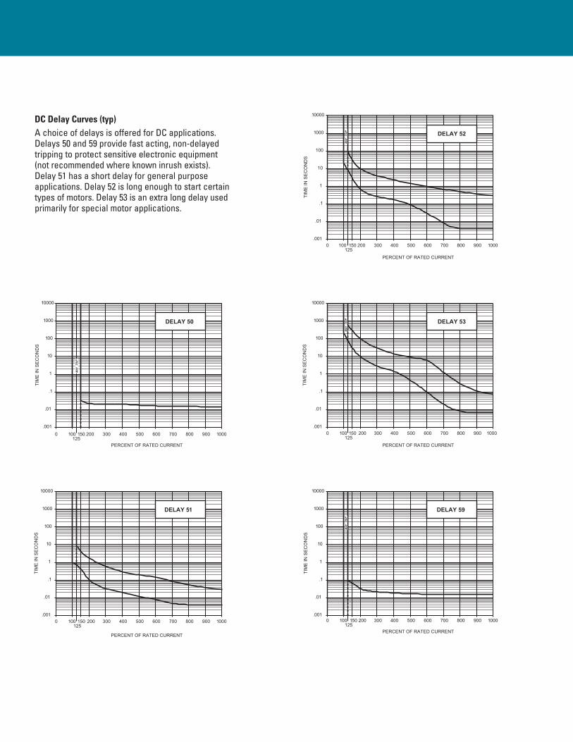
DC Delay Curves (typ)A choice of delays is offered for DC applications. Delays 50 and 59 provide fast acting, non-delayed tripping to protect sensitive electronic equipment (not recommended where known inrush exists). Delay 51 has a short delay for general purpose applications. Delay 52 is long enough to start certain types of motors. Delay 53 is an extra long delay used primarily for special motor applications.

DELAY 40
800700600500400300200150125
1000
TIM
E I
N S
EC
ON
DS
10
1
.1
1000
100
.01
10000
.001
PERCENT OF RATED CURRENT
1000900
DELAY 41
800700600500400300200150125
1000
TIM
E IN
SE
CO
ND
S
10
1
.1
1000
100
.01
10000
.001
PERCENT OF RATED CURRENT
1000900
DELAY 42
900 1000
PERCENT OF RATED CURRENT
.001
10000
.01
100
1000
.1
1
10
TIM
E I
N S
EC
ON
DS
0 100125
150 200 300 400 500 600 700 800
DELAY 43
900 1000
PERCENT OF RATED CURRENT
.001
10000
.01
100
1000
.1
1
10T
IME
IN
SE
CO
ND
S
0 100125
150 200 300 400 500 600 700 800
DELAY 49
900 1000
PERCENT OF RATED CURRENT
.001
10000
.01
100
1000
.1
1
10
TIM
E IN
SE
CO
ND
S
0 100130
150 200 300 400 500 600 700 800
MA
Y
TR
IP
MA
Y
TR
IPM
AY
T
RIP
MA
Y
TR
IPM
AY
T
RIP
400Hz Delay Curves (typ)A choice of delays is offered for 400Hz applications. Delays 40 and 49 are fast acting, non-delayed tripping to protect sensitive electronic equipment (not recommended where known inrush exists). Delay 41 has a short delay for general purpose applications. Delay 42 is long enough to start certain types of motor and most transformers and capacitor loads. Delay 43 is an extra long delay primarily for special motor applications.
APL/
UPL
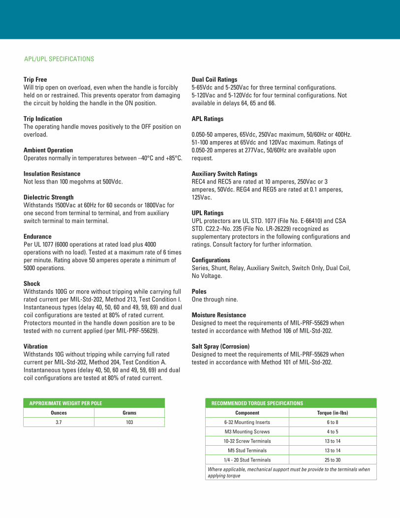
Trip FreeWill trip open on overload, even when the handle is forcibly held on or restrained. This prevents operator from damaging the circuit by holding the handle in the ON position.
Trip IndicationThe operating handle moves positively to the OFF position on overload.
Ambient OperationOperates normally in temperatures between –40°C and +85°C.
Insulation ResistanceNot less than 100 megohms at 500Vdc.
Dielectric StrengthWithstands 1500Vac at 60Hz for 60 seconds or 1800Vac for one second from terminal to terminal, and from auxiliary switch terminal to main terminal.
EndurancePer UL 1077 (6000 operations at rated load plus 4000 operations with no load). Tested at a maximum rate of 6 times per minute. Rating above 50 amperes operate a minimum of 5000 operations.
ShockWithstands 100G or more without tripping while carrying full rated current per MIL-Std-202, Method 213, Test Condition I. Instantaneous types (delay 40, 50, 60 and 49, 59, 69) and dual coil configurations are tested at 80% of rated current. Protectors mounted in the handle down position are to be tested with no current applied (per MIL-PRF-55629).
VibrationWithstands 10G without tripping while carrying full rated current per MIL-Std-202, Method 204, Test Condition A. Instantaneous types (delay 40, 50, 60 and 49, 59, 69) and dual coil configurations are tested at 80% of rated current.
Dual Coil Ratings5-65Vdc and 5-250Vac for three terminal configurations. 5-120Vac and 5-120Vdc for four terminal configurations. Not available in delays 64, 65 and 66. APL Ratings
0.050-50 amperes, 65Vdc, 250Vac maximum, 50/60Hz or 400Hz. 51-100 amperes at 65Vdc and 120Vac maximum. Ratings of 0.050-20 amperes at 277Vac, 50/60Hz are available upon request.
Auxiliary Switch Ratings REC4 and REC5 are rated at 10 amperes, 250Vac or 3 amperes, 50Vdc. REG4 and REG5 are rated at 0.1 amperes, 125Vac.
UPL RatingsUPL protectors are UL STD. 1077 (File No. E-66410) and CSA STD. C22.2–No. 235 (File No. LR-26229) recognized as supplementary protectors in the following configurations and ratings. Consult factory for further information.
ConfigurationsSeries, Shunt, Relay, Auxiliary Switch, Switch Only, Dual Coil, No Voltage.
PolesOne through nine.
Moisture ResistanceDesigned to meet the requirements of MIL-PRF-55629 when tested in accordance with Method 106 of MIL-Std-202.
Salt Spray (Corrosion)Designed to meet the requirements of MIL-PRF-55629 when tested in accordance with Method 101 of MIL-Std-202.
APL/UPL SPECIFICATIONS
APPROXIMATE WEIGHT PER POLE
Ounces Grams
3.7 103
RECOMMENDED TORQUE SPECIFICATIONS
Component Torque (in-lbs)
6-32 Mounting Inserts 6 to 8
M3 Mounting Screws 4 to 5
10-32 Screw Terminals 13 to 14
M5 Stud Terminals 13 to 14
1/4 - 20 Stud Terminals 25 to 30
Where applicable, mechanical support must be provide to the terminals when applying torque

APL/UPL - NOMINAL DCR / IMPEDANCE
Current Ratings (Amps)
Resistance (ohms) Impedance (ohms) Impedance (ohms)
DC Delays AC, 50/60Hz Delays AC, 400Hz Delays
50 59 51, 52, 53 Dual Coil 51, 52, 53 60 69 600, 61, 62
71, 72, 7364, 65, 66 Dual Coil 61, 62 40, 49 41, 42, 43
0.05 162 540 460 640 174 419 582 691 1975 1195
0.10 35.4 105 155 150 42.5 103.4 119.0 160 495 284
0.50 1.2 4.2 4.5 5.6 1.9 4 4.1 6.2 22 12
1.0 .236 1.02 1.2 1.41 .41 .955 1.08 1.56 5.01 2.72
5.0 .021 .048 .059 .070 .030 .045 .048 .068 .240 .140
10.0 .0060 .0121 .0140 .0160 .0075 .0105 .0134 .0174 .0520 .0283
15.0 .0040 .0067 .0092 .0100 .0038 .0068 .0070 .0120 .0260 .0140
20.0 .0032 .0047 .0052 .0070 .0024 .0049 .0050 .0069 .0140 .0088
30.0 .0021 .0036 .0036 .0040 .0022 .0032 .0035 .0037 .0079 .0043
50.0 .0020 .0024 .0026 .0023 .0020 .0020 .0025 .0030 .0036 .0028
Notes: DCR and impedance based on 100% rated current applied and stablized a minimum of one hour.Tolerance: .02 amperes to 2.5 amperes, ± 20%; 2.6 amperes to 20 amperes, ± 25%; 21 amperes to 50 amperes, ± 50%. Consult factory for special values and for coil impedance of delays not shown
APL/UPL - RATINGS
Configurations Current Ratings (Amps) Maximum Voltage Ratings Interrupting Capacity (Amps) Series Fuse
Series and Shunt
0.050 - 50 65Vdc 5000 None
0.050 - 100 65Vdc 3000 None
0.050 - 60 120Vac (50/60Hz) 1000 None
0.050 - 50 120Vac (50/60Hz) 5000 4X (120 max.)
0.050 - 20 277Vac (50/60Hz) 5000 4X
0.050 - 50 250Vac (50/60Hz) 5000 4X (120 max.)
0.050 - 50 120Vac (400Hz) 1500 None
21 - 50 250Vac (400Hz) 1000 None
0.050 - 20 250Vac (400Hz) 2100 None
Relay
0.050 - 50 50Vdc — —
0.050 - 50 120Vac (50/60Hz) — —
0.050 - 50 120Vac (400Hz) — —
0.050 - 50 250Vac (50/60Hz-400Hz) — —
Switch Only
50 amperes max. 65Vdc — — —
100 amperes max. 32Vdc — — —
50 amperes max. 250Vac (50/60Hz) — — —
50 amperes max. 250Vac (400Hz) — — —
Notes: DC units do not require series fusing.277Vac: A circuit protector with this voltage rating is intended for 277Vac per pole single phase source only usage. (e.g.) If a two or three pole breaker is marked 277Vac, all line terminals must be connected to the same phase, assuming the 277Vac is taken from line to neutral of a three phase 277/480Vac system.
APL/
UPL

Moisture ResistanceDesigned to meet the requirements of MIL-PRF-55629 when tested in accordance with Method 106 of MIL-Std-202.
Salt Spray (Corrosion)Designed to meet the requirements of MIL-PRF-55629 when tested in accordance with Method 101 of MIL-Std-202.
MPL RatingsMPL protectors are UL (File No. E-41607) and CSA (File No. LR-26229) recognized as manual, across the line starters, in the following configurations and ratings. Consult factory for further information.
ConfigurationsSeries only with and without auxiliary switch.
PolesOne, two or three.
ShockWithstands 100G or more without tripping while carrying full rated current per MIL-Std-202, Method 213, Test Condition I. Instantaneous types (delay 40, 50, 60 and 49, 59, 69) are tested at 80% of rated current. Breakers mounted in the handle down position are to be tested with no current applied (per MIL-PRF-55629).
VibrationWithstands 10G without tripping while carrying full rated current per MIL-Std-202, Method 204, Test Condition A. Instantaneous types (delay 40, 50, 60 and 49, 59, 69) are tested at 80% of rated current.
MPL SPECIFICATIONS

APPROXIMATE WEIGHT PER POLE
Ounces Grams
3.7 103
RECOMMENDED TORQUE SPECIFICATIONS
Component Torque (in-lbs)
6-32 Mounting Inserts 6 to 8
M3 Mounting Screws 4 to 5
10-32 Screw Terminals 13 to 14
M5 Stud Terminals 13 to 14
1/4 - 20 Stud Terminals 25 to 30
Where applicable, mechanical support must be provide to the terminals when applying torque
MPL - RATINGS
Current Ratings (Amps) Maximum Voltage Ratings Horsepower, Single Phase Ratings Three Phase (Note A)
0.050 - 50 65Vdc 1 —
0.050 - 50 120Vac (50/60Hz) 3 7.5
0.050 - 20 240Vac (50/60Hz) 3 5
0.050 - 20 277Vac (50/60Hz) 3 5
Note: AC units require maximum of 4X rated series fusing: DC units do not require series fusing. A: Two or three poles breaking
APL/
UPL

APL/UPL DECISION TABLES
How to Order
The ordering code for APL/UPL circuit protectors may be determined by following the steps in the decision tables shown here.
The coding given permits a self-assigning part number; other configurations may require a factory assigned part number. Typical examples are units with mixed ratings, combinations of styles or constructions not listed in the third decision table, etc.
With these, it is suggested that order entry be by description and/or drawings and a part number will be assigned. Additionally, it is a standard policy to establish a factory assigned part number wherever a descriptive drawing exists to provide cross reference, traceability and manufacturing control.
When specifying a protector for AC motor start or high inrush applications, the peak amplitude and surge duration should be specified for factory assistance in rating selection.
For example, the code shown is the code for a two pole UPL protector with series trip, 20 ampere rating, 50/60Hz. short time delay construction in all poles.
To determine the ordering number for your particular APL/UPL unit, simply follow the steps shown. You may use this number to place an order or as a reference for further questions you may have.
Notes:
A The most common current values for 100% of rated current are those listed. Please consult an Airpax office orsales representa-tive for other values.
B All APL/UPL protectors are constructed with stainless steel springs and plated parts. As noted in the specifications, all meet normal requirements for moisture and salt spray resistance. If fungus resistance is required in addition to moisture and salt spray resistance, special procedures and markings are employed.
C Terminals will be supplied as #10-32 threaded studs up to 50 amperes. Above this amperage terminals will be ¼ -28 threaded studs. All standard units will be supplied with a hex nut and two flat washers on each threaded terminal.
D When metric threaded inserts are specified, breakers rated at 50 amperes and below will be supplied with metric threaded terminals. For breakers rated above 50 amperes, ¼ -28 threaded terminals will be supplied.
E Black handle standard.
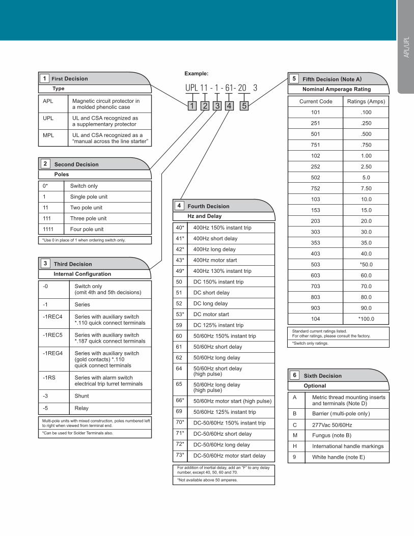
UPL 11 - 1 - 61- 20 3
APL/
UPL