APLITEX MAQUETA inglés - Aplicaciones técnicas del ... · PDF file5.1 ORIFICE...
13
FLOW MEASUREMENT 5 PRIMARY ELEMENTS 5.1 ORIFICE PLATE & RESTRICTION ORIFICE 5.2 CERAMIC PRIMARY DIFFERENTIAL PRESSURE DEVICES 5.3 SPECTACLE BLINDS 5.4 FLANGES ASSEMBLY WITH ORIFICE PLATE OR RESTRICTION ORIFICE 5.5 METER RUN 5.6 DIAPHRAGM WITH ANNULAR CHAMBERS 5.7 DIAPHRAGM WITH INCORPORATED TAPS 5.8 AVERAGING PITOT TUBE 5.9 VENTURI TUBE 5.10 ISA 1932 NOZZLE 5.11 ASME NOZZLE 5.12 FLOW ACCESORIES www.aplitexsl.com Information: +34 93 399 37 11
Transcript of APLITEX MAQUETA inglés - Aplicaciones técnicas del ... · PDF file5.1 ORIFICE...

F L O W M E A S U R E M E N T
5 PRIMARY ELEMENTS
5.1 ORIFICE PLATE & RESTRICTION ORIFICE
5.2 CERAMIC PRIMARY DIFFERENTIAL PRESSURE DEVICES
5.3 SPECTACLE BLINDS
5.4 FLANGES ASSEMBLY WITH ORIFICE PLATE OR RESTRICTION ORIFICE
5.5 METER RUN
5.6 DIAPHRAGM WITH ANNULAR CHAMBERS
5.7 DIAPHRAGM WITH INCORPORATEDTAPS
5.8 AVERAGING PITOT TUBE
5.9 VENTURI TUBE
5.10 ISA 1932 NOZZLE
5.11 ASME NOZZLE
5.12 FLOW ACCESORIES
www.aplitexsl.comInformation: +34 93 399 37 11
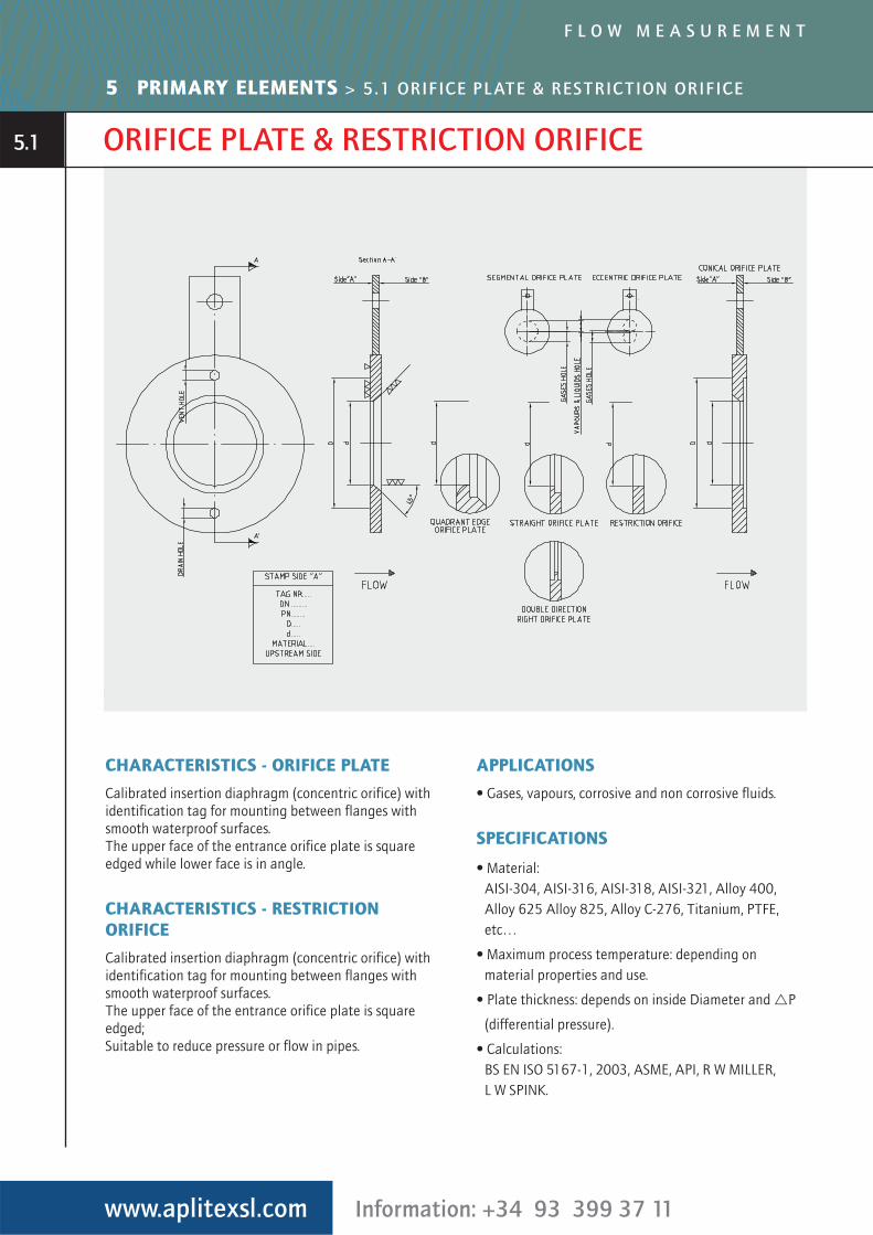
ORIFICE PLATE & RESTRICTION ORIFICE
CHARACTERISTICS - ORIFICE PLATE
Calibrated insertion diaphragm (concentric orifice) withidentification tag for mounting between flanges withsmooth waterproof surfaces.The upper face of the entrance orifice plate is squareedged while lower face is in angle.
CHARACTERISTICS - RESTRICTIONORIFICE
Calibrated insertion diaphragm (concentric orifice) withidentification tag for mounting between flanges withsmooth waterproof surfaces.The upper face of the entrance orifice plate is squareedged;Suitable to reduce pressure or flow in pipes.
APPLICATIONS
• Gases, vapours, corrosive and non corrosive fluids.
SPECIFICATIONS
• Material: AISI-304, AISI-316, AISI-318, AISI-321, Alloy 400,Alloy 625 Alloy 825, Alloy C-276, Titanium, PTFE,etc…
• Maximum process temperature: depending onmaterial properties and use.
• Plate thickness: depends on inside Diameter and �P
(differential pressure).
• Calculations: BS EN ISO 5167-1, 2003, ASME, API, R W MILLER, L W SPINK.
www.aplitexsl.com Information: +34 93 399 37 11
F L O W M E A S U R E M E N T
5 PRIMARY ELEMENTS > 5.1 ORIFICE PLATE & RESTRICTION ORIFICE
5.1
CERAMIC PRIMARY DIFFERENTIAL PRESSURE DEVICES
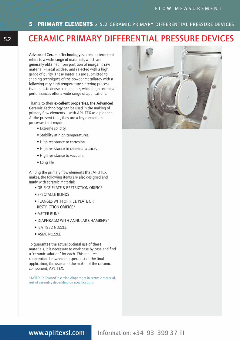
Advanced Ceramic Technology is a recent term thatrefers to a wide range of materials, which aregenerally obtained from partition of inorganic rawmaterial –metal oxides-, and selected with a highgrade of purity. These materials are submitted toshaping techniques of the powder metallurgy with afollowing very high temperature sintering processthat leads to dense components, which high technicalperformances offer a wide range of applications.
Thanks to their excellent properties, the AdvancedCeramic Technology can be used in the making ofprimary flow elements – with APLITEX as a pioneer.At the present time, they are a key element inprocesses that require:
• Extreme solidity.
• Stability at high temperatures.
• High resistance to corrosion.
• High resistance to chemical attacks.
• High resistance to vacuum.
• Long life.
Among the primary flow elements that APLITEXmakes, the following items are also designed andmade with ceramic material:
• ORIFICE PLATE & RESTRICTION ORIFICE
• SPECTACLE BLINDS
• FLANGES WITH ORIFICE PLATE ORRESTRICTION ORIFICE*
• METER RUN*
• DIAPHRAGM WITH ANNULAR CHAMBERS*
• ISA 1932 NOZZLE
• ASME NOZZLE
To guarantee the actual optimal use of thesematerials, it is necessary to work case by case and finda “ceramic solution” for each. This requirescooperation between the specialist of the finalapplication, the user, and the maker of the ceramiccomponent, APLITEX.
*NOTE: Calibrated insertion diaphragm in ceramic material,rest of assembly depending on specifications
www.aplitexsl.com Information: +34 93 399 37 11
F L O W M E A S U R E M E N T
5 PRIMARY ELEMENTS > 5.2 CERAMIC PRIMARY DIFFERENTIAL PRESSURE DEVICES
5.2
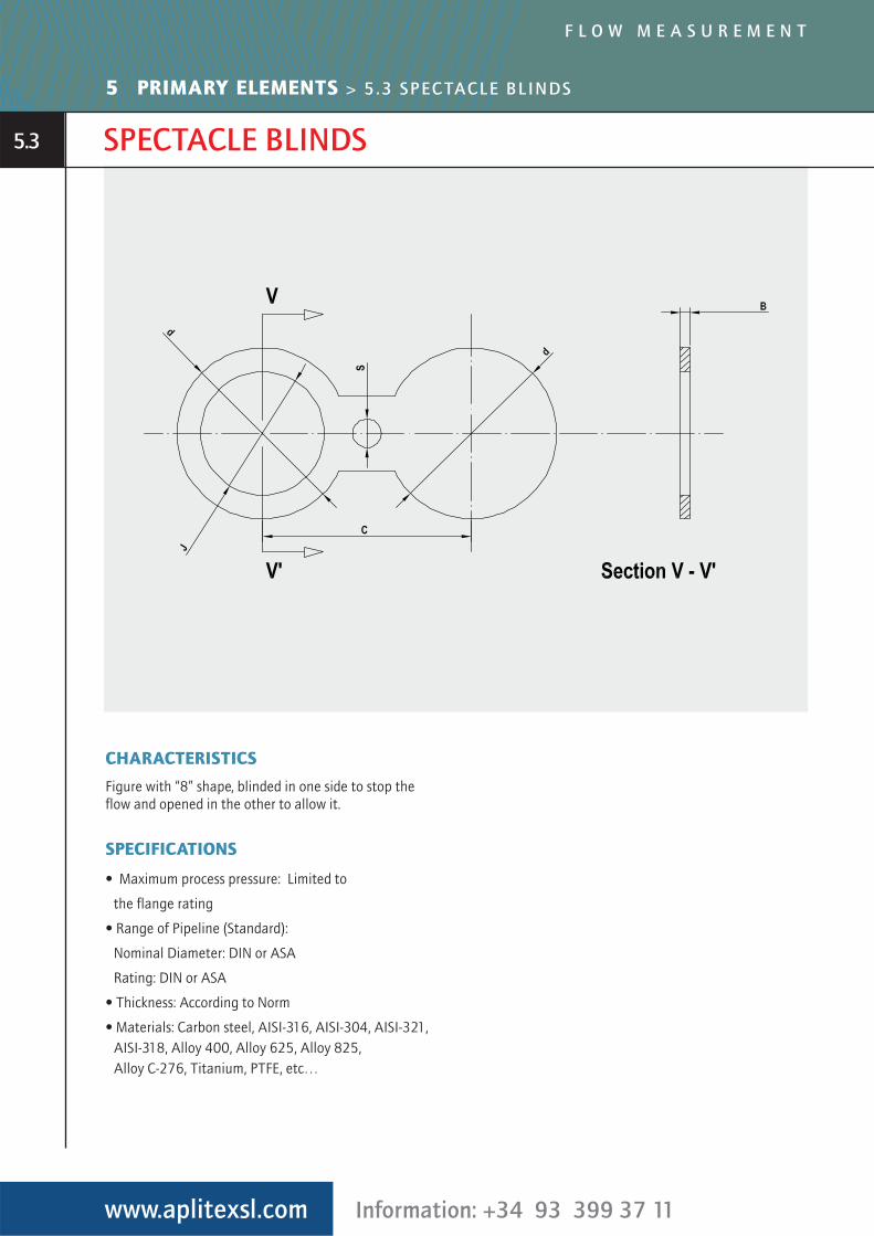
SPECTACLE BLINDS
CHARACTERISTICS
Figure with “8” shape, blinded in one side to stop theflow and opened in the other to allow it.
SPECIFICATIONS
• Maximum process pressure: Limited to
the flange rating
• Range of Pipeline (Standard):
Nominal Diameter: DIN or ASA
Rating: DIN or ASA
• Thickness: According to Norm
• Materials: Carbon steel, AISI-316, AISI-304, AISI-321,AISI-318, Alloy 400, Alloy 625, Alloy 825, Alloy C-276, Titanium, PTFE, etc…
www.aplitexsl.com Information: +34 93 399 37 11
F L O W M E A S U R E M E N T
5 PRIMARY ELEMENTS > 5.3 SPECTACLE BLINDS
5.3
www.aplitexsl.com Information: +34 93 399 37 11
F L O W M E A S U R E M E N T
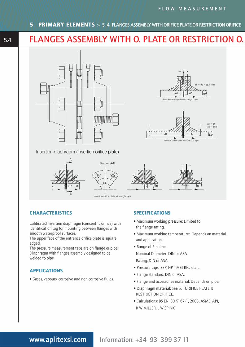
FLANGES ASSEMBLY WITH O. PLATE OR RESTRICTION O.
CHARACTERISTICS
Calibrated insertion diaphragm (concentric orifice) withidentification tag for mounting between flanges withsmooth waterproof surfaces.The upper face of the entrance orifice plate is squareedged.The pressure measurement taps are on flange or pipe.Diaphragm with flanges assembly designed to bewelded to pipe.
APPLICATIONS
• Gases, vapours, corrosive and non corrosive fluids.
SPECIFICATIONS
• Maximum working pressure: Limited to the flange rating.
• Maximum working temperature: Depends on materialand application.
• Range of Pipeline:
Nominal Diameter: DIN or ASA
Rating: DIN or ASA
• Pressure taps: BSP, NPT, METRIC, etc…
• Flange standard: DIN or ASA.
• Flange and accessories material: Depends on pipe.
• Diaphragm material: See 5.1 ORIFICE PLATE & RESTRICTION ORIFICE.
• Calculations: BS EN ISO 5167-1, 2003, ASME, API,
R W MILLER, L W SPINK.
5 PRIMARY ELEMENTS > 5.4 FLANGES ASSEMBLY WITH ORIFICE PLATE OR RESTRICTION ORIFICE
5.4
METER RUN
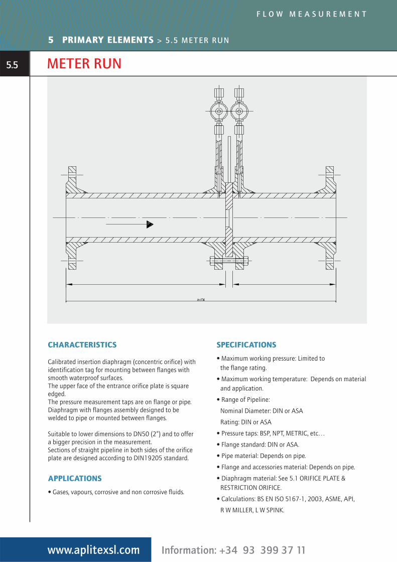
CHARACTERISTICS
Calibrated insertion diaphragm (concentric orifice) withidentification tag for mounting between flanges withsmooth waterproof surfaces.The upper face of the entrance orifice plate is squareedged.The pressure measurement taps are on flange or pipe.Diaphragm with flanges assembly designed to bewelded to pipe or mounted between flanges.
Suitable to lower dimensions to DN50 (2”) and to offera bigger precision in the measurement.Sections of straight pipeline in both sides of the orificeplate are designed according to DIN19205 standard.
APPLICATIONS
• Gases, vapours, corrosive and non corrosive fluids.
SPECIFICATIONS
• Maximum working pressure: Limited to the flange rating.
• Maximum working temperature: Depends on materialand application.
• Range of Pipeline:
Nominal Diameter: DIN or ASA
Rating: DIN or ASA
• Pressure taps: BSP, NPT, METRIC, etc…
• Flange standard: DIN or ASA.
• Pipe material: Depends on pipe.
• Flange and accessories material: Depends on pipe.
• Diaphragm material: See 5.1 ORIFICE PLATE & RESTRICTION ORIFICE.
• Calculations: BS EN ISO 5167-1, 2003, ASME, API,
R W MILLER, L W SPINK.
www.aplitexsl.com Information: +34 93 399 37 11
F L O W M E A S U R E M E N T
5 PRIMARY ELEMENTS > 5.5 METER RUN
5.5
ANNULAR CHAMBERS
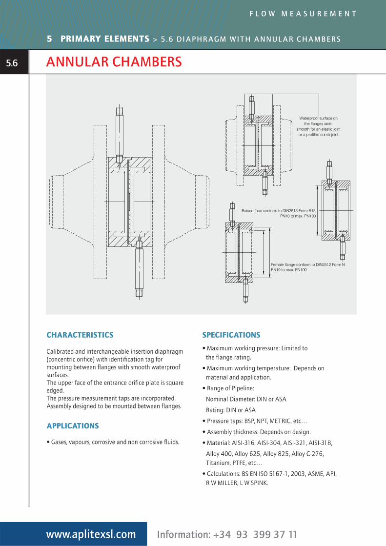
CHARACTERISTICS
Calibrated and interchangeable insertion diaphragm(concentric orifice) with identification tag formounting between flanges with smooth waterproofsurfaces.The upper face of the entrance orifice plate is squareedged.The pressure measurement taps are incorporated.Assembly designed to be mounted between flanges.
APPLICATIONS
• Gases, vapours, corrosive and non corrosive fluids.
SPECIFICATIONS
• Maximum working pressure: Limited to the flange rating.
• Maximum working temperature: Depends onmaterial and application.
• Range of Pipeline:
Nominal Diameter: DIN or ASA
Rating: DIN or ASA
• Pressure taps: BSP, NPT, METRIC, etc…
• Assembly thickness: Depends on design.
• Material: AISI-316, AISI-304, AISI-321, AISI-318,
Alloy 400, Alloy 625, Alloy 825, Alloy C-276,Titanium, PTFE, etc…
• Calculations: BS EN ISO 5167-1, 2003, ASME, API,R W MILLER, L W SPINK.
www.aplitexsl.com Information: +34 93 399 37 11
F L O W M E A S U R E M E N T
5 PRIMARY ELEMENTS > 5.6 DIAPHRAGM WITH ANNULAR CHAMBERS
5.6
INCORPORATED TAPS
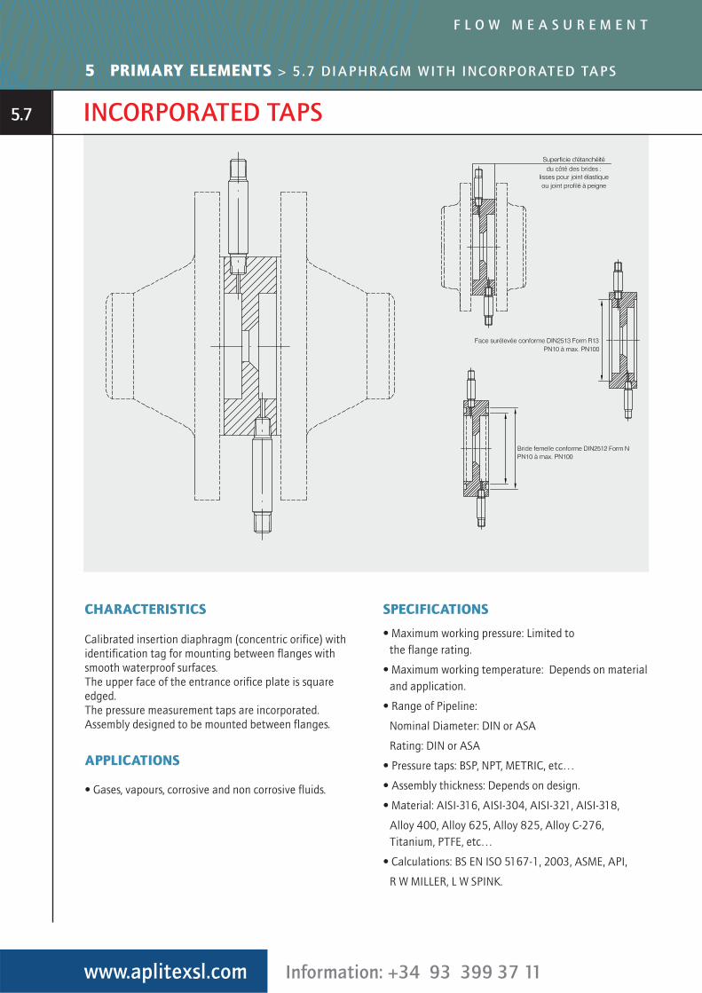
CHARACTERISTICS
Calibrated insertion diaphragm (concentric orifice) withidentification tag for mounting between flanges withsmooth waterproof surfaces.The upper face of the entrance orifice plate is squareedged.The pressure measurement taps are incorporated.Assembly designed to be mounted between flanges.
APPLICATIONS
• Gases, vapours, corrosive and non corrosive fluids.
SPECIFICATIONS
• Maximum working pressure: Limited to the flange rating.
• Maximum working temperature: Depends on materialand application.
• Range of Pipeline:
Nominal Diameter: DIN or ASA
Rating: DIN or ASA
• Pressure taps: BSP, NPT, METRIC, etc…
• Assembly thickness: Depends on design.
• Material: AISI-316, AISI-304, AISI-321, AISI-318,
Alloy 400, Alloy 625, Alloy 825, Alloy C-276,Titanium, PTFE, etc…
• Calculations: BS EN ISO 5167-1, 2003, ASME, API,
R W MILLER, L W SPINK.
www.aplitexsl.com Information: +34 93 399 37 11
F L O W M E A S U R E M E N T
5 PRIMARY ELEMENTS > 5.7 DIAPHRAGM WITH INCORPORATED TAPS
5.7
AVERAGING PITOT TUBE
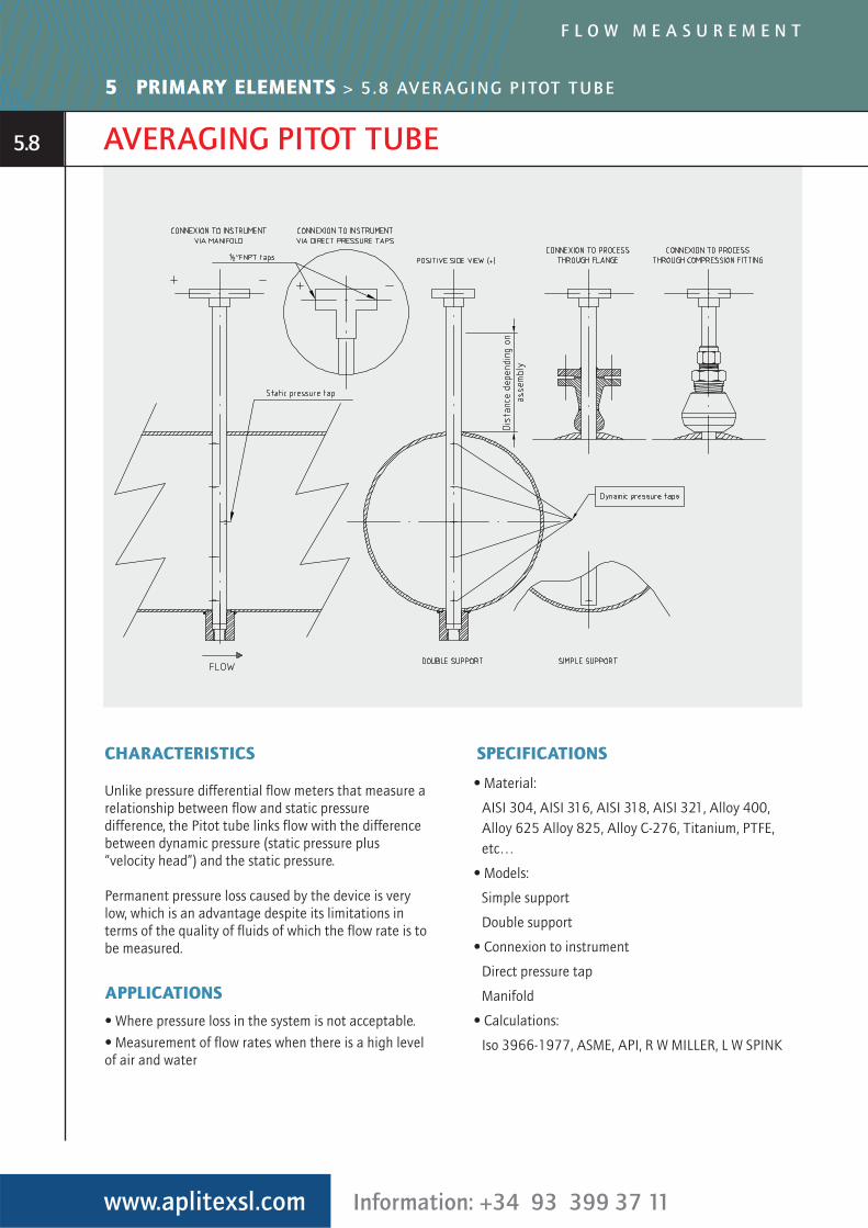
CHARACTERISTICS
Unlike pressure differential flow meters that measure arelationship between flow and static pressuredifference, the Pitot tube links flow with the differencebetween dynamic pressure (static pressure plus“velocity head”) and the static pressure.
Permanent pressure loss caused by the device is verylow, which is an advantage despite its limitations interms of the quality of fluids of which the flow rate is tobe measured.
APPLICATIONS
• Where pressure loss in the system is not acceptable.
• Measurement of flow rates when there is a high level of air and water
SPECIFICATIONS
• Material:
AISI 304, AISI 316, AISI 318, AISI 321, Alloy 400,Alloy 625 Alloy 825, Alloy C-276, Titanium, PTFE,etc…
• Models:
Simple support
Double support
• Connexion to instrument
Direct pressure tap
Manifold
• Calculations:
Iso 3966-1977, ASME, API, R W MILLER, L W SPINK
www.aplitexsl.com Information: +34 93 399 37 11
F L O W M E A S U R E M E N T
5 PRIMARY ELEMENTS > 5.8 AVERAGING PITOT TUBE
5.8
VENTURI TUBE
www.aplitexsl.com Information: +34 93 399 37 11
F L O W M E A S U R E M E N T
5 PRIMARY ELEMENTS > 5.9 VENTURI TUBE
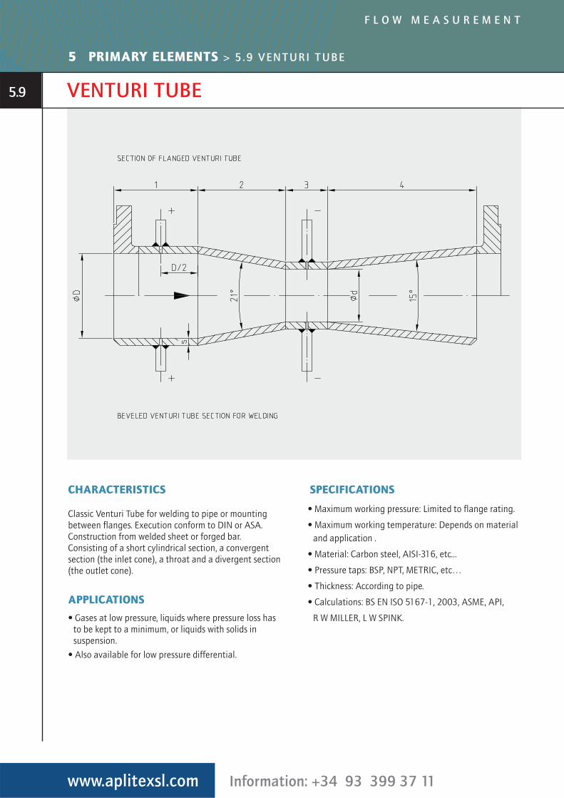
CHARACTERISTICS
Classic Venturi Tube for welding to pipe or mountingbetween flanges. Execution conform to DIN or ASA.Construction from welded sheet or forged bar.Consisting of a short cylindrical section, a convergentsection (the inlet cone), a throat and a divergent section(the outlet cone).
APPLICATIONS
• Gases at low pressure, liquids where pressure loss hasto be kept to a minimum, or liquids with solids insuspension.
• Also available for low pressure differential.
SPECIFICATIONS
• Maximum working pressure: Limited to flange rating.
• Maximum working temperature: Depends on materialand application .
• Material: Carbon steel, AISI-316, etc...
• Pressure taps: BSP, NPT, METRIC, etc…
• Thickness: According to pipe.
• Calculations: BS EN ISO 5167-1, 2003, ASME, API,
R W MILLER, L W SPINK.
5.9
ISA 1932 NOZZLE
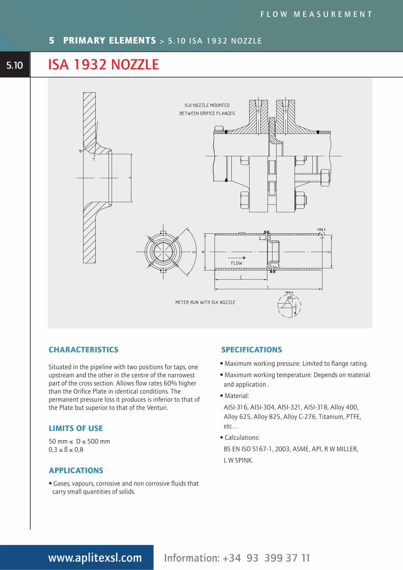
CHARACTERISTICS
Situated in the pipeline with two positions for taps, oneupstream and the other in the centre of the narrowestpart of the cross section. Allows flow rates 60% higherthan the Orifice Plate in identical conditions. Thepermanent pressure loss it produces is inferior to that ofthe Plate but superior to that of the Venturi.
LIMITS OF USE
50 mm ≤ D ≤ 500 mm0,3 ≤ ß ≤ 0,8
APPLICATIONS
• Gases, vapours, corrosive and non corrosive fluids thatcarry small quantities of solids.
SPECIFICATIONS
• Maximum working pressure: Limited to flange rating.
• Maximum working temperature: Depends on materialand application .
• Material:
AISI-316, AISI-304, AISI-321, AISI-318, Alloy 400,Alloy 625, Alloy 825, Alloy C-276, Titanium, PTFE,etc…
• Calculations:
BS EN ISO 5167-1, 2003, ASME, API, R W MILLER,
L W SPINK.
www.aplitexsl.com Information: +34 93 399 37 11
F L O W M E A S U R E M E N T
5 PRIMARY ELEMENTS > 5.10 ISA 1932 NOZZLE
5.10
ASME NOZZLE
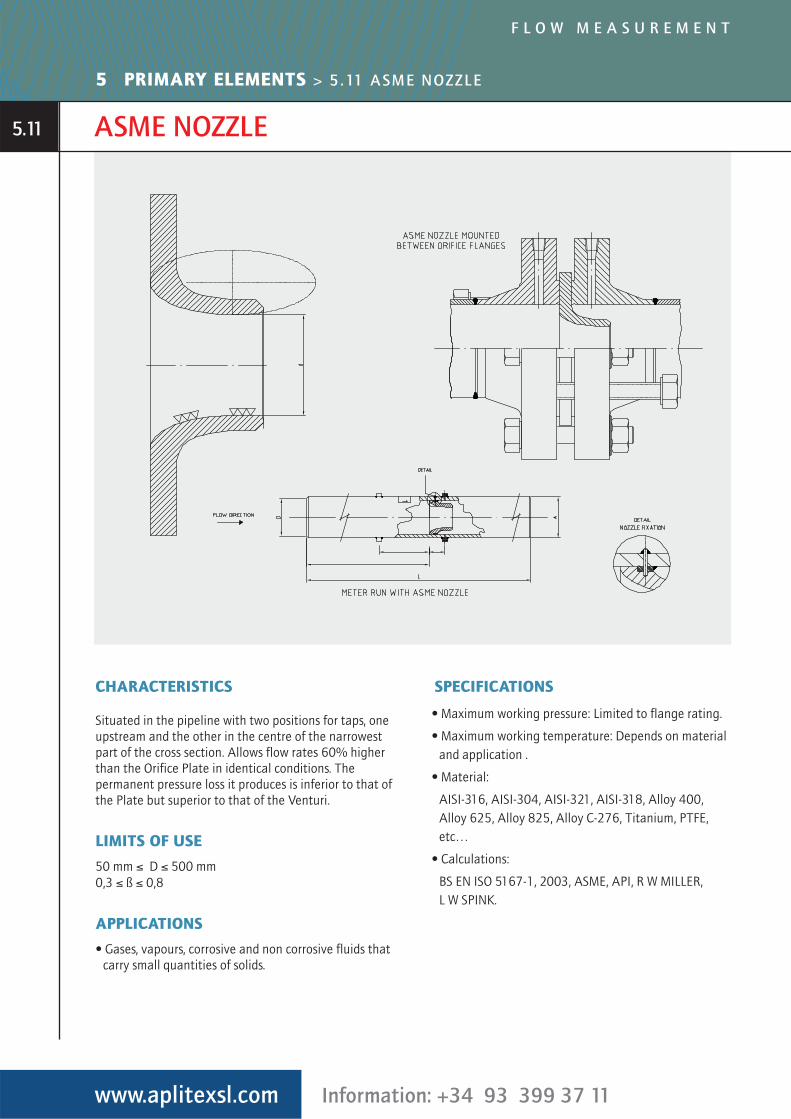
CHARACTERISTICS
Situated in the pipeline with two positions for taps, oneupstream and the other in the centre of the narrowestpart of the cross section. Allows flow rates 60% higherthan the Orifice Plate in identical conditions. Thepermanent pressure loss it produces is inferior to that ofthe Plate but superior to that of the Venturi.
LIMITS OF USE
50 mm ≤ D ≤ 500 mm0,3 ≤ ß ≤ 0,8
APPLICATIONS
• Gases, vapours, corrosive and non corrosive fluids thatcarry small quantities of solids.
SPECIFICATIONS
• Maximum working pressure: Limited to flange rating.
• Maximum working temperature: Depends on materialand application .
• Material:
AISI-316, AISI-304, AISI-321, AISI-318, Alloy 400,Alloy 625, Alloy 825, Alloy C-276, Titanium, PTFE,etc…
• Calculations:
BS EN ISO 5167-1, 2003, ASME, API, R W MILLER, L W SPINK.
www.aplitexsl.com Information: +34 93 399 37 11
F L O W M E A S U R E M E N T
5 PRIMARY ELEMENTS > 5.11 ASME NOZZLE
5.11
FLOW ACCESORIES
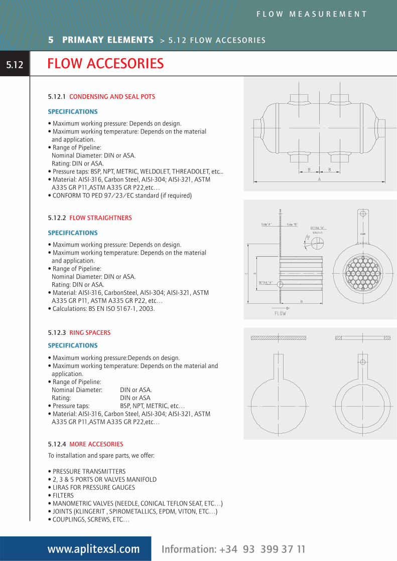
5.12.1 CONDENSING AND SEAL POTS
SPECIFICATIONS
• Maximum working pressure: Depends on design.• Maximum working temperature: Depends on the material
and application. • Range of Pipeline:
Nominal Diameter: DIN or ASA.Rating: DIN or ASA.
• Pressure taps: BSP, NPT, METRIC, WELDOLET, THREADOLET, etc...• Material: AISI-316, Carbon Steel, AISI-304; AISI-321, ASTM
A335 GR P11,ASTM A335 GR P22,etc…• CONFORM TO PED 97/23/EC standard (if required)
5.12.2 FLOW STRAIGHTNERS
SPECIFICATIONS
• Maximum working pressure: Depends on design.• Maximum working temperature: Depends on the material
and application. • Range of Pipeline:
Nominal Diameter: DIN or ASA.Rating: DIN or ASA.
• Material: AISI-316, CarbonSteel, AISI-304; AISI-321, ASTMA335 GR P11, ASTM A335 GR P22, etc…
• Calculations: BS EN ISO 5167-1, 2003.
5.12.3 RING SPACERS
SPECIFICATIONS
• Maximum working pressure:Depends on design.• Maximum working temperature: Depends on the material and
application. • Range of Pipeline:
Nominal Diameter: DIN or ASA.Rating: DIN or ASA
• Pressure taps: BSP, NPT, METRIC, etc…• Material: AISI-316, Carbon Steel, AISI-304; AISI-321, ASTM
A335 GR P11,ASTM A335 GR P22,etc…
5.12.4 MORE ACCESORIES
To installation and spare parts, we offer:
• PRESSURE TRANSMITTERS• 2, 3 & 5 PORTS OR VALVES MANIFOLD• LIRAS FOR PRESSURE GAUGES• FILTERS• MANOMETRIC VALVES (NEEDLE, CONICAL TEFLON SEAT, ETC…)• JOINTS (KLINGERIT , SPIROMETALLICS, EPDM, VITON, ETC…)• COUPLINGS, SCREWS, ETC…
www.aplitexsl.com Information: +34 93 399 37 11
F L O W M E A S U R E M E N T
5 PRIMARY ELEMENTS > 5.12 FLOW ACCESORIES
5.12