API RP 2A WSD 21st - Computers and Structuresdocs.csiamerica.com/.../SFD-API-RP-2A-WSD-21st.pdf ·...
23
Steel Frame Design Manual API RP 2A WSD 21 st
Transcript of API RP 2A WSD 21st - Computers and Structuresdocs.csiamerica.com/.../SFD-API-RP-2A-WSD-21st.pdf ·...
Steel Frame Design ManualAPI RP 2A WSD 21st
API RP 2A-WSD 21st Steel Frame Design Manual
for
ISO SAP102816M10 Rev. 0 October 2016 Proudly developed in the United States of America

COPYRIGHT
Copyright © Computers and Structures, Inc., 1978 – 2016 All rights reserved.
The CSI Logo® and SAP2000® are registered trademarks of Computers and Structures, Inc.
The computer program SAP2000® and all associated documentation are proprietary and copyrighted products. Worldwide rights of ownership rest with Computers and Structures, Inc. Unlicensed use of this program or reproduction of documentation in any form, without prior written authorization from Computers and Structures, Inc., is explicitly prohibited.
No part of this publication may be reproduced or distributed in any form or by any means, or stored in a database or retrieval system, without the prior written permission of the publisher.
Further information and copies of this documentation may be obtained from:
Computers and Structures, Inc. www.csiamerica.com
[email protected] (for general information) [email protected] (for technical questions)
DISCLAIMER
CONSIDERABLE TIME, EFFORT, AND EXPENSE HAVE GONE INTO THE DEVELOPMENT AND TESTING OF THIS SOFTWARE. HOWEVER, THE USER ACCEPTS AND UNDERSTANDS THAT NO WARRANTY IS EXPRESSED OR IMPLIED BY THE DEVELOPERS OR THE DISTRIBUTORS ON THE ACCURACY OR THE RELIABILITY OF THIS PRODUCT.
THIS PRODUCT IS A PRACTICAL AND POWERFUL TOOL FOR STRUCTURAL DESIGN. HOWEVER, THE USER MUST EXPLICITLY UNDERSTAND THE BASIC ASSUMPTIONS OF THE SOFTWARE MODELING, ANALYSIS, AND DESIGN ALGORITHMS AND COMPENSATE FOR THE ASPECTS THAT ARE NOT ADDRESSED.
THE INFORMATION PRODUCED BY THE SOFTWARE MUST BE CHECKED BY A QUALIFIED AND EXPERIENCED ENGINEER. THE ENGINEER MUST INDEPENDENTLY VERIFY THE RESULTS AND TAKE PROFESSIONAL RESPONSIBILITY FOR THE INFORMATION THAT IS USED.

Contents
1 Introduction 1
1.1 Units 1
1.2 Axes Notation 1
1.3 Symbols 1
2 Member Design 4
2.1 Safety Factors 4
2.2 Tension Check 4
2.3 Compression Check 5
2.4 Flexure Check 5
2.5 Shear Check 6
2.6 Hoop Buckling Check 6
2.7 Axial Tension and Bending Check 7
2.8 Axial Compression and Bending Check 7
3 Joint Design 9
3.1 Joint Geometry 9
3.2 Punching Shear Method 10
3.2.1 Design Loads 10 3.2.2 Allowable Stresses 10 3.2.3 Axial and Bending Check 11 3.2.4 Overlapping Joints 12
3.3 Nominal Load Method 12
i

Steel Frame Design API RP 2A-WSD 21st Introduction
3.3.1 Allowable Capacities 12 3.3.2 Axial and Bending Check 13 3.3.3 Overlapping Joints 13
4 Supplements 2 and 3 14
4.1 Joint Design 14
4.1.1 Allowable Capacities 14 4.1.2 Axial and Bending Check 16 4.1.3 Overlapping Joints 16
5 References 17
Units ii

1 Introduction
This manual describes the steel frame design algorithms in the software for API Recommended Practice 2A-WSD 21st Edition (American Petroleum Institute, 2000). The design algorithms in the software for API RP 2A-WSD 21st cover allowable stress checks for typical structural elements used in offshore steel structures, as detailed in this manual. Such elements are tubular members and tubular joints. For other types of structural elements, the software uses AISC ASD 9th Edition. Requirements of the code not documented in this manual should be considered using other methods.
This manual documents the design details for cylindrical sections having thickness t ≥ 6mm, D/t < 300. Members of other section shapes are designed in accordance with AISC ASD 9th Edition (American Institute of Steel Construction, 1989).
It is important to read this entire manual before using the design algorithms to become familiar with any limitations of the algorithms or assumptions that have been made.
1.1 Units
The API RP 2A-WSD design code is based on kip, inch, and second units and as such, so is this manual, unless noted otherwise. Any units, imperial, metric, or MKS may be used in the software in conjunction with API RP 2A-WSD design.
1.2 Axes Notation
The software analysis results refer to the member local axes system, which consists of the 2-2 axis and the 3-3 axis. The API RP 2A-WSD design code refers to x-x and y-y axes, which are equivalent to the software 3-3 and 2-2 axes, respectively. These notations may be used interchangeably in the design algorithms, although every effort has been made to use the design code convention where possible.
1.3 Symbols
The following table provides a list of the symbols used in this manual, along with a short
Units 1

Steel Frame Design API RP 2A-WSD 21st Introduction
description. Where possible, the same symbol from the design code is used in this manual.
A Cross sectional area, in2
C Critical elastic buckling coefficient
Ch Critical hoop buckling coefficient
Cm Reduction factor
D Outside diameter, in
E Young’s modulus of elasticity, ksi
fa Design tensile stress, ksi
Fa Allowable compressive stress, ksi
fb Design bending stress, ksi
Fb Allowable bending stress, ksi
Fe’ Euler stress, ksi
fh Hoop stress due to hydrostatic pressure, ksi
Fhc Critical hoop buckling stress, ksi
Fhe Elastic hoop buckling stress, ksi
Ft Allowable tensile stress, ksi
fv Design beam shear stress, ksi
Fv Allowable beam shear stress, ksi
fvt Design torsional shear stress, ksi
Fvt Allowable torsional shear stress, ksi
fx Design compressive stress, ksi
Fxc Inelastic local buckling stress, ksi
Fxe Elastic local buckling stress, ksi
Fy Yield strength, ksi
g Gap distance, in
Ip Polar moment of inertia, in4
K Effective length factor
l Unbraced length, in
l Circumference of brace contact with chord, neglecting overlap, in
L Length between stiffening rings, diaphragms, or end connections, in
l1 Circumference of brace portion that contacts the chord, in
l2 Projected chord length of overlapping weld, in
M Bending moment, kip-in
M Geometric parameter
Symbols 2
Steel Frame Design API RP 2A-WSD 21st Introduction
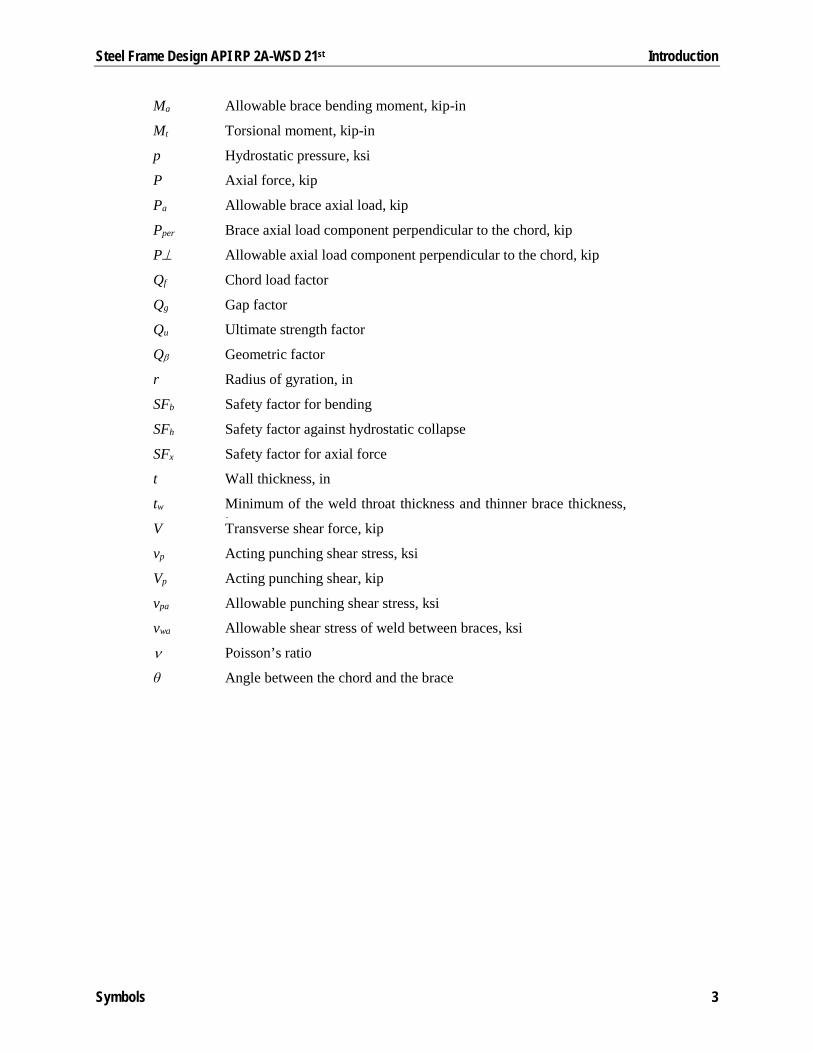
Ma Allowable brace bending moment, kip-in
Mt Torsional moment, kip-in
p Hydrostatic pressure, ksi
P Axial force, kip
Pa Allowable brace axial load, kip
Pper Brace axial load component perpendicular to the chord, kip
P⊥ Allowable axial load component perpendicular to the chord, kip
Qf Chord load factor
Qg Gap factor
Qu Ultimate strength factor
Qβ Geometric factor
r Radius of gyration, in
SFb Safety factor for bending
SFh Safety factor against hydrostatic collapse
SFx Safety factor for axial force
t Wall thickness, in
tw Minimum of the weld throat thickness and thinner brace thickness, i V Transverse shear force, kip
vp Acting punching shear stress, ksi
Vp Acting punching shear, kip
vpa Allowable punching shear stress, ksi
vwa Allowable shear stress of weld between braces, ksi
ν Poisson’s ratio
θ Angle between the chord and the brace
Symbols 3

2 Member Design
This chapter provides the details of the structural steel design and stress check algorithms that are used for cylindrical member design and checking at each output station in accordance with API RP 2A-WSD.
Cylindrical members subjected solely to axial tension, axial compression, bending, shear, or hydrostatic pressure are designed in accordance with API RP 2A-WSD Sections 3.2.1 to 3.2.5, respectively. Cylindrical members subjected to combined loads without hydrostatic pressure are designed in accordance with API RP 2A-WSD Sections 3.3.1 and 3.3.2. Cylindrical members subjected to combined loads with hydrostatic pressure are designed in accordance with API RP 2A-WSD Sections 3.3.3 and 3.3.4.
2.1 Safety Factors
The safety factors used in calculating allowable stresses in the following sections are defined as:
Table 1 - Safety factors
Loading
Design Condition Axial Tension
Axial Compression
Bending Hoop Compression
Basic allowable stresses 1.67 2.0 𝐹𝐹𝑦𝑦 𝐹𝐹𝑏𝑏⁄ 2.0 One-third increase in allowable
stresses is permitted 1.25 1.5 𝐹𝐹𝑦𝑦 (1.33𝐹𝐹𝑏𝑏)⁄ 1.5
2.2 Tension Check
Members subjected to axial tension are checked for the following condition:
𝑓𝑓𝑎𝑎𝐹𝐹𝑡𝑡≤ 1.0 [API 3.2.1]
The allowable tensile stress, Ft, is defined as:
Safety Factors 4
Steel Frame Design API RP 2A-WSD 21st Member Design
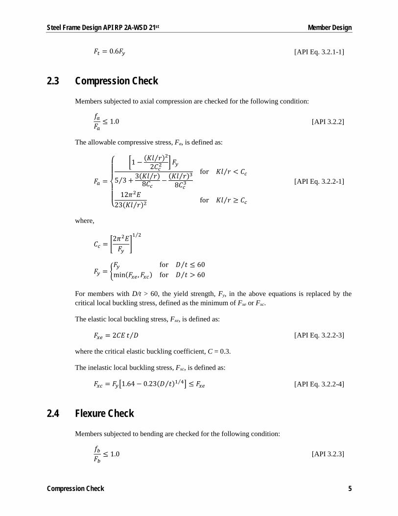
𝐹𝐹𝑡𝑡 = 0.6𝐹𝐹𝑦𝑦 [API Eq. 3.2.1-1]
2.3 Compression Check
Members subjected to axial compression are checked for the following condition:
𝑓𝑓𝑎𝑎𝐹𝐹𝑎𝑎≤ 1.0 [API 3.2.2]
The allowable compressive stress, Fa, is defined as:
𝐹𝐹𝑎𝑎 =
⎩⎪⎪⎨
⎪⎪⎧ �1 − (𝐾𝐾𝐾𝐾 𝑟𝑟⁄ )2
2𝐶𝐶𝑐𝑐2�𝐹𝐹𝑦𝑦
5 3⁄ + 3(𝐾𝐾𝐾𝐾 𝑟𝑟⁄ )8𝐶𝐶𝑐𝑐
− (𝐾𝐾𝐾𝐾 𝑟𝑟⁄ )38𝐶𝐶𝑐𝑐3
for 𝐾𝐾𝐾𝐾 𝑟𝑟⁄ < 𝐶𝐶𝑐𝑐
12𝜋𝜋2𝐸𝐸23(𝐾𝐾𝐾𝐾 𝑟𝑟⁄ )2 for 𝐾𝐾𝐾𝐾 𝑟𝑟⁄ ≥ 𝐶𝐶𝑐𝑐
[API Eq. 3.2.2-1]
where,
𝐶𝐶𝑐𝑐 = �2𝜋𝜋2𝐸𝐸𝐹𝐹𝑦𝑦
�1 2⁄
𝐹𝐹𝑦𝑦 = �𝐹𝐹𝑦𝑦 for 𝐷𝐷 𝑡𝑡⁄ ≤ 60min(𝐹𝐹𝑥𝑥𝑥𝑥 ,𝐹𝐹𝑥𝑥𝑐𝑐) for 𝐷𝐷 𝑡𝑡⁄ > 60
For members with D/t > 60, the yield strength, Fy, in the above equations is replaced by the critical local buckling stress, defined as the minimum of Fxe or Fxc.
The elastic local buckling stress, Fxe, is defined as:
𝐹𝐹𝑥𝑥𝑥𝑥 = 2𝐶𝐶𝐸𝐸 𝑡𝑡 𝐷𝐷⁄ [API Eq. 3.2.2-3]
where the critical elastic buckling coefficient, C = 0.3.
The inelastic local buckling stress, Fxc, is defined as:
𝐹𝐹𝑥𝑥𝑐𝑐 = 𝐹𝐹𝑦𝑦�1.64− 0.23(𝐷𝐷 𝑡𝑡⁄ )1 4⁄ � ≤ 𝐹𝐹𝑥𝑥𝑥𝑥 [API Eq. 3.2.2-4]
2.4 Flexure Check
Members subjected to bending are checked for the following condition:
𝑓𝑓𝑏𝑏𝐹𝐹𝑏𝑏
≤ 1.0 [API 3.2.3]
Compression Check 5
Steel Frame Design API RP 2A-WSD 21st Member Design
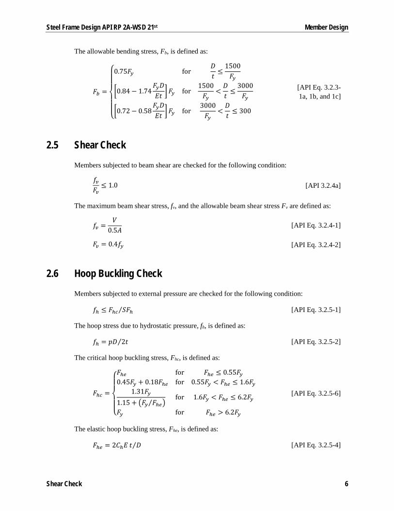
The allowable bending stress, Fb, is defined as:
𝐹𝐹𝑏𝑏 =
⎩⎪⎪⎨
⎪⎪⎧0.75𝐹𝐹𝑦𝑦 for
𝐷𝐷𝑡𝑡≤
1500𝐹𝐹𝑦𝑦
�0.84− 1.74𝐹𝐹𝑦𝑦𝐷𝐷𝐸𝐸𝑡𝑡 �
𝐹𝐹𝑦𝑦 for1500𝐹𝐹𝑦𝑦
<𝐷𝐷𝑡𝑡≤
3000𝐹𝐹𝑦𝑦
�0.72− 0.58𝐹𝐹𝑦𝑦𝐷𝐷𝐸𝐸𝑡𝑡 �
𝐹𝐹𝑦𝑦 for3000𝐹𝐹𝑦𝑦
<𝐷𝐷𝑡𝑡≤ 300
[API Eq. 3.2.3-1a, 1b, and 1c]
2.5 Shear Check
Members subjected to beam shear are checked for the following condition:
𝑓𝑓𝑣𝑣𝐹𝐹𝑣𝑣≤ 1.0 [API 3.2.4a]
The maximum beam shear stress, fv, and the allowable beam shear stress Fv are defined as:
𝑓𝑓𝑣𝑣 =𝑉𝑉
0.5𝐴𝐴 [API Eq. 3.2.4-1]
𝐹𝐹𝑣𝑣 = 0.4𝑓𝑓𝑦𝑦 [API Eq. 3.2.4-2]
2.6 Hoop Buckling Check
Members subjected to external pressure are checked for the following condition:
𝑓𝑓ℎ ≤ 𝐹𝐹ℎ𝑐𝑐 𝑆𝑆𝐹𝐹ℎ⁄ [API Eq. 3.2.5-1]
The hoop stress due to hydrostatic pressure, fh, is defined as:
𝑓𝑓ℎ = 𝑝𝑝𝐷𝐷 2𝑡𝑡⁄ [API Eq. 3.2.5-2]
The critical hoop buckling stress, Fhc, is defined as:
𝐹𝐹ℎ𝑐𝑐 =
⎩⎪⎨
⎪⎧𝐹𝐹ℎ𝑥𝑥 for 𝐹𝐹ℎ𝑥𝑥 ≤ 0.55𝐹𝐹𝑦𝑦0.45𝐹𝐹𝑦𝑦 + 0.18𝐹𝐹ℎ𝑥𝑥 for 0.55𝐹𝐹𝑦𝑦 < 𝐹𝐹ℎ𝑥𝑥 ≤ 1.6𝐹𝐹𝑦𝑦
1.31𝐹𝐹𝑦𝑦1.15 + �𝐹𝐹𝑦𝑦 𝐹𝐹ℎ𝑥𝑥⁄ �
for 1.6𝐹𝐹𝑦𝑦 < 𝐹𝐹ℎ𝑥𝑥 ≤ 6.2𝐹𝐹𝑦𝑦
𝐹𝐹𝑦𝑦 for 𝐹𝐹ℎ𝑥𝑥 > 6.2𝐹𝐹𝑦𝑦
[API Eq. 3.2.5-6]
The elastic hoop buckling stress, Fhe, is defined as:
𝐹𝐹ℎ𝑥𝑥 = 2𝐶𝐶ℎ𝐸𝐸 𝑡𝑡 𝐷𝐷⁄ [API Eq. 3.2.5-4]
Shear Check 6
Steel Frame Design API RP 2A-WSD 21st Member Design
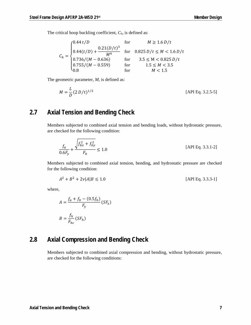
The critical hoop buckling coefficient, Ch, is defined as:
𝐶𝐶ℎ =
⎩⎪⎨
⎪⎧
0.44 𝑡𝑡 𝐷𝐷⁄ for 𝑀𝑀 ≥ 1.6𝐷𝐷 𝑡𝑡⁄
0.44(𝑡𝑡 𝐷𝐷⁄ ) +0.21(𝐷𝐷 𝑡𝑡⁄ )3
𝑀𝑀4 for 0.825𝐷𝐷 𝑡𝑡⁄ ≤ 𝑀𝑀 < 1.6𝐷𝐷 𝑡𝑡⁄
0.736 (𝑀𝑀 − 0.636)⁄ for 3.5 ≤ M < 0.825𝐷𝐷 𝑡𝑡⁄0.755 (𝑀𝑀 − 0.559)⁄ for 1.5 ≤ 𝑀𝑀 < 3.50.8 for 𝑀𝑀 < 1.5
The geometric parameter, M, is defined as:
𝑀𝑀 =𝐿𝐿𝐷𝐷
(2𝐷𝐷 𝑡𝑡⁄ )1 2⁄ [API Eq. 3.2.5-5]
2.7 Axial Tension and Bending Check
Members subjected to combined axial tension and bending loads, without hydrostatic pressure, are checked for the following condition:
𝑓𝑓𝑎𝑎0.6𝐹𝐹𝑦𝑦
+�𝑓𝑓𝑏𝑏𝑥𝑥2 + 𝑓𝑓𝑏𝑏𝑦𝑦2
𝐹𝐹𝑏𝑏≤ 1.0 [API Eq. 3.3.1-2]
Members subjected to combined axial tension, bending, and hydrostatic pressure are checked for the following condition:
𝐴𝐴2 + 𝐵𝐵2 + 2𝜈𝜈|𝐴𝐴|𝐵𝐵 ≤ 1.0 [API Eq. 3.3.3-1]
where,
𝐴𝐴 =𝑓𝑓𝑎𝑎 + 𝑓𝑓𝑏𝑏 − (0.5𝑓𝑓ℎ)
𝐹𝐹𝑦𝑦(𝑆𝑆𝐹𝐹𝑥𝑥)
𝐵𝐵 =𝑓𝑓ℎ𝐹𝐹ℎ𝑐𝑐
(𝑆𝑆𝐹𝐹ℎ)
2.8 Axial Compression and Bending Check
Members subjected to combined axial compression and bending, without hydrostatic pressure, are checked for the following conditions:
Axial Tension and Bending Check 7

Steel Frame Design API RP 2A-WSD 21st Member Design
𝑓𝑓𝑎𝑎𝐹𝐹𝑎𝑎
+
��𝐶𝐶𝑚𝑚𝑥𝑥𝑓𝑓𝑏𝑏𝑥𝑥1 − 𝑓𝑓𝑎𝑎
𝐹𝐹𝑥𝑥𝑥𝑥′�
2
+ �𝐶𝐶𝑚𝑚𝑦𝑦𝑓𝑓𝑏𝑏𝑦𝑦1 − 𝑓𝑓𝑎𝑎
𝐹𝐹𝑥𝑥𝑦𝑦′�
2
𝐹𝐹𝑏𝑏≤ 1.0
[API Eq. 3.3.1-4]
𝑓𝑓𝑎𝑎0.6𝐹𝐹𝑦𝑦
+�𝑓𝑓𝑏𝑏𝑥𝑥2 + 𝑓𝑓𝑏𝑏𝑦𝑦2
𝐹𝐹𝑏𝑏≤ 1.0 [API Eq. 3.3.1-2]
where,
𝐹𝐹𝑥𝑥′ =12𝜋𝜋2𝐸𝐸
23(𝐾𝐾𝐾𝐾 𝑟𝑟⁄ )2 [AISC H1]
The reduction factors, Cmx and Cmy are calculated according to AISC H1.
If 𝑓𝑓𝑎𝑎𝐹𝐹𝑎𝑎≤ 0.15, the previous two conditions are substituted by the following condition:
𝑓𝑓𝑎𝑎𝐹𝐹𝑎𝑎
+�𝑓𝑓𝑏𝑏𝑥𝑥2 + 𝑓𝑓𝑏𝑏𝑦𝑦2
𝐹𝐹𝑏𝑏≤ 1.0 [API Eq. 3.3.1-3]
Members subjected to combined axial compression, bending, and hydrostatic pressure are checked for the following conditions:
𝑓𝑓𝑎𝑎 + (0.5𝑓𝑓ℎ)𝐹𝐹𝑥𝑥𝑐𝑐
(𝑆𝑆𝐹𝐹𝑥𝑥) +𝑓𝑓𝑏𝑏𝐹𝐹𝑦𝑦
(𝑆𝑆𝐹𝐹𝑏𝑏) ≤ 1.0 [API Eq. 3.3.4-1]
𝑆𝑆𝐹𝐹ℎ𝑓𝑓ℎ𝐹𝐹ℎ𝑐𝑐
≤ 1.0 [API Eq. 3.3.4-2]
If 𝑓𝑓𝑥𝑥 > 0.5𝐹𝐹ℎ𝑎𝑎, the following condition is also satisfied:
𝑓𝑓𝑥𝑥 − 0.5𝐹𝐹ℎ𝑎𝑎𝐹𝐹𝑎𝑎𝑎𝑎 − 0.5𝐹𝐹ℎ𝑎𝑎
+ �𝑓𝑓ℎ𝐹𝐹ℎ𝑎𝑎
�2
≤ 1.0 [API Eq. 3.3.4-3]
where,
F𝑎𝑎𝑎𝑎 =𝐹𝐹𝑥𝑥𝑥𝑥𝑆𝑆𝐹𝐹𝑥𝑥
𝐹𝐹ℎ𝑎𝑎 =𝐹𝐹ℎ𝑥𝑥𝑆𝑆𝐹𝐹ℎ
𝑓𝑓𝑥𝑥 = 𝑓𝑓𝑎𝑎 + 𝑓𝑓𝑏𝑏 + (0.5𝑓𝑓ℎ)
Axial Compression and Bending Check 8

3 Joint Design
This chapter provides the details of the joint punching load check algorithms that are used for tubular joints in accordance with API RP 2A-WSD Sections 4.3.1 and 4.3.2.
API RP 2A-WSD allows the joints to be designed on the basis of punching shear or nominal loads in the braces. Both methods are available and documented in the following sections.
3.1 Joint Geometry
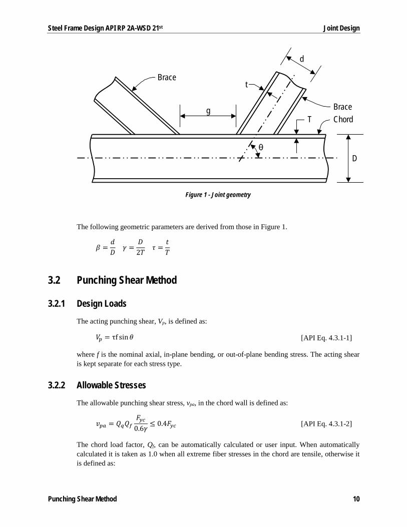
Figure 1 illustrates some of the geometric parameters used in the punching load check.
d Brace diameter, in
D Chord diameter, in
g Gap distance, in
t Brace thickness, in
T Chord thickness, in
θ Angle measured from the chord to the brace
Joint Geometry 9
Steel Frame Design API RP 2A-WSD 21st Joint Design
Figure 1 - Joint geometry
The following geometric parameters are derived from those in Figure 1.
𝛽𝛽 =𝑑𝑑𝐷𝐷
𝛾𝛾 =𝐷𝐷2𝑇𝑇
𝜏𝜏 =𝑡𝑡𝑇𝑇
3.2 Punching Shear Method
3.2.1 Design Loads
The acting punching shear, Vp, is defined as:
𝑉𝑉𝑝𝑝 = τf sin𝜃𝜃 [API Eq. 4.3.1-1]
where f is the nominal axial, in-plane bending, or out-of-plane bending stress. The acting shear is kept separate for each stress type.
3.2.2 Allowable Stresses
The allowable punching shear stress, vpa, in the chord wall is defined as:
𝑣𝑣𝑝𝑝𝑎𝑎 = 𝑄𝑄𝑞𝑞𝑄𝑄𝑓𝑓𝐹𝐹𝑦𝑦𝑐𝑐
0.6𝛾𝛾≤ 0.4𝐹𝐹𝑦𝑦𝑐𝑐 [API Eq. 4.3.1-2]
The chord load factor, Qf, can be automatically calculated or user input. When automatically calculated it is taken as 1.0 when all extreme fiber stresses in the chord are tensile, otherwise it is defined as:
T
D
g
d
t
θ
ChordBrace
Brace
Punching Shear Method 10

Steel Frame Design API RP 2A-WSD 21st Joint Design
𝑄𝑄𝑓𝑓 = 1.0 − λγ𝐴𝐴2
where,
𝜆𝜆 = �0.030 for brace axial stress0.045 for brace in− plane bending stress0.021 for brace out− of − plane bending stress
𝐴𝐴 =�𝑓𝑓�̅�𝐴𝐴𝐴2 + 𝑓𝑓�̅�𝐼𝐼𝐼𝐼𝐼2 + 𝑓𝑓�̅�𝑂𝐼𝐼𝐼𝐼2
0.6𝐹𝐹𝑦𝑦𝑥𝑥
The factor Qq is determined based on API Table 4.3.1-1.
Table 2 – Factor, Qq
Brace Action
Joint Class Axial Tension
Axial Compression
In-plane Bending
Out-of-plane Bending
K overlap 1.8
(3.72 + 0.67 𝛽𝛽⁄ ) (1.37 + 0.67 𝛽𝛽⁄ )𝑄𝑄𝛽𝛽
K gap (1.10 + 0.20 𝛽𝛽⁄ )𝑄𝑄𝑔𝑔
T&Y (1.10 + 0.20 𝛽𝛽⁄ )
Cross w/o diaphragm (1.10 + 0.20 𝛽𝛽⁄ ) (0.75 + 0.20 𝛽𝛽⁄ )𝑄𝑄𝛽𝛽
Cross w/ diaphragm (1.10 + 0.20 𝛽𝛽⁄ )
The geometric factor, Qβ, is defined as:
𝑄𝑄𝛽𝛽 = �0.3
𝛽𝛽(1 − 0.833𝛽𝛽) for 𝛽𝛽 > 0.6
1.0 for 𝛽𝛽 ≤ 0.6 [API Table 4.3.1-1]
The gap factor, Qg, is defined as:
𝑄𝑄𝑔𝑔 = �1.8 − 0.1𝑔𝑔 𝑇𝑇⁄ ≥ 1.0 for 𝛾𝛾 ≤ 201.8 − 4𝑔𝑔 𝐷𝐷⁄ ≥ 1.0 for 𝛾𝛾 > 20 [API Table 4.3.1-1]
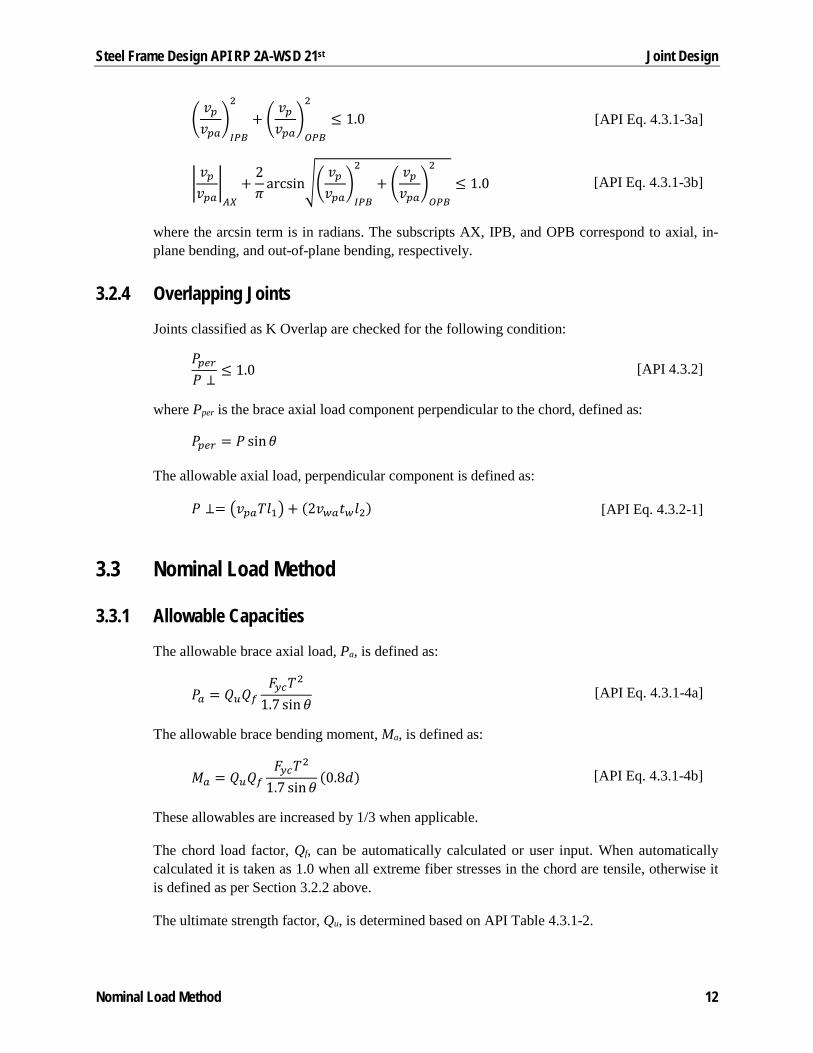
3.2.3 Axial and Bending Check
Joints with braces subjected to combined axial and/or bending loads are checked for the following conditions:
Punching Shear Method 11
Steel Frame Design API RP 2A-WSD 21st Joint Design
�𝑣𝑣𝑝𝑝𝑣𝑣𝑝𝑝𝑎𝑎
�𝐼𝐼𝐼𝐼𝐼𝐼
2
+ �𝑣𝑣𝑝𝑝𝑣𝑣𝑝𝑝𝑎𝑎
�𝑂𝑂𝐼𝐼𝐼𝐼
2
≤ 1.0 [API Eq. 4.3.1-3a]
�𝑣𝑣𝑝𝑝𝑣𝑣𝑝𝑝𝑎𝑎
�𝐴𝐴𝐴𝐴
+2𝜋𝜋
arcsin��𝑣𝑣𝑝𝑝𝑣𝑣𝑝𝑝𝑎𝑎
�𝐼𝐼𝐼𝐼𝐼𝐼
2
+ �𝑣𝑣𝑝𝑝𝑣𝑣𝑝𝑝𝑎𝑎
�𝑂𝑂𝐼𝐼𝐼𝐼
2
≤ 1.0 [API Eq. 4.3.1-3b]
where the arcsin term is in radians. The subscripts AX, IPB, and OPB correspond to axial, in-plane bending, and out-of-plane bending, respectively.
3.2.4 Overlapping Joints
Joints classified as K Overlap are checked for the following condition:
𝑃𝑃𝑝𝑝𝑥𝑥𝑝𝑝𝑃𝑃 ⊥
≤ 1.0 [API 4.3.2]
where Pper is the brace axial load component perpendicular to the chord, defined as:
𝑃𝑃𝑝𝑝𝑥𝑥𝑝𝑝 = 𝑃𝑃 sin𝜃𝜃
The allowable axial load, perpendicular component is defined as:
𝑃𝑃 ⊥= �𝑣𝑣𝑝𝑝𝑎𝑎𝑇𝑇𝐾𝐾1�+ (2𝑣𝑣𝑤𝑤𝑎𝑎𝑡𝑡𝑤𝑤𝐾𝐾2) [API Eq. 4.3.2-1]
3.3 Nominal Load Method
3.3.1 Allowable Capacities
The allowable brace axial load, Pa, is defined as:
𝑃𝑃𝑎𝑎 = 𝑄𝑄𝑢𝑢𝑄𝑄𝑓𝑓𝐹𝐹𝑦𝑦𝑐𝑐𝑇𝑇2
1.7 sin𝜃𝜃 [API Eq. 4.3.1-4a]
The allowable brace bending moment, Ma, is defined as:
𝑀𝑀𝑎𝑎 = 𝑄𝑄𝑢𝑢𝑄𝑄𝑓𝑓𝐹𝐹𝑦𝑦𝑐𝑐𝑇𝑇2
1.7 sin𝜃𝜃(0.8𝑑𝑑) [API Eq. 4.3.1-4b]
These allowables are increased by 1/3 when applicable.
The chord load factor, Qf, can be automatically calculated or user input. When automatically calculated it is taken as 1.0 when all extreme fiber stresses in the chord are tensile, otherwise it is defined as per Section 3.2.2 above.
The ultimate strength factor, Qu, is determined based on API Table 4.3.1-2.
Nominal Load Method 12

Steel Frame Design API RP 2A-WSD 21st Joint Design
Table 3 – Factor, Qu
Brace Action
Joint Class Axial Tension
Axial Compression
In-plane Bending
Out-of-plane Bending
K (3.4 + 19𝛽𝛽)𝑄𝑄𝑔𝑔
(3.4 + 19𝛽𝛽) (3.4 + 7𝛽𝛽)𝑄𝑄𝛽𝛽 T&Y (3.4 + 19𝛽𝛽)
Cross w/o diaphragm (3.4 + 19𝛽𝛽) (3.4 + 19𝛽𝛽)𝑄𝑄𝛽𝛽
Cross w/ diaphragm (3.4 + 19𝛽𝛽)
The geometric factor, Qβ, and the gap factor, Qg, are defined in Section 3.2.2 above.
3.3.2 Axial and Bending Check
Joints with braces subjected to combined axial and/or bending loads are checked for the following conditions:
�𝑀𝑀𝑀𝑀𝑎𝑎
�𝐼𝐼𝐼𝐼𝐼𝐼
2+ �
𝑀𝑀𝑀𝑀𝑎𝑎
�𝑂𝑂𝐼𝐼𝐼𝐼
2≤ 1.0 [API Eq. 4.3.1-5a]
�𝑃𝑃𝑃𝑃𝑎𝑎�+
2𝜋𝜋
arcsin��𝑀𝑀𝑀𝑀𝑎𝑎
�𝐼𝐼𝐼𝐼𝐼𝐼
2+ �
𝑀𝑀𝑀𝑀𝑎𝑎
�𝑂𝑂𝐼𝐼𝐼𝐼
2≤ 1.0 [API Eq. 4.3.1-5b]
where the arcsin term is in radians. The subscripts AX, IPB, and OPB correspond to axial, in-plane bending, and out-of-plane bending, respectively.
3.3.3 Overlapping Joints
Joints classified as K Overlap are checked for the following condition:
𝑃𝑃𝑝𝑝𝑥𝑥𝑝𝑝𝑃𝑃 ⊥
≤ 1.0 [API 4.3.2]
where Pper is the brace axial load component perpendicular to the chord, defined as:
𝑃𝑃𝑝𝑝𝑥𝑥𝑝𝑝 = 𝑃𝑃 sin𝜃𝜃
The allowable axial load, perpendicular component is defined as:
𝑃𝑃 ⊥= �𝑃𝑃𝑎𝑎 sin𝜃𝜃𝐾𝐾1𝐾𝐾� + (2𝑣𝑣𝑤𝑤𝑎𝑎𝑡𝑡𝑤𝑤𝐾𝐾2) [API Eq. 4.3.2-2]
Nominal Load Method 13
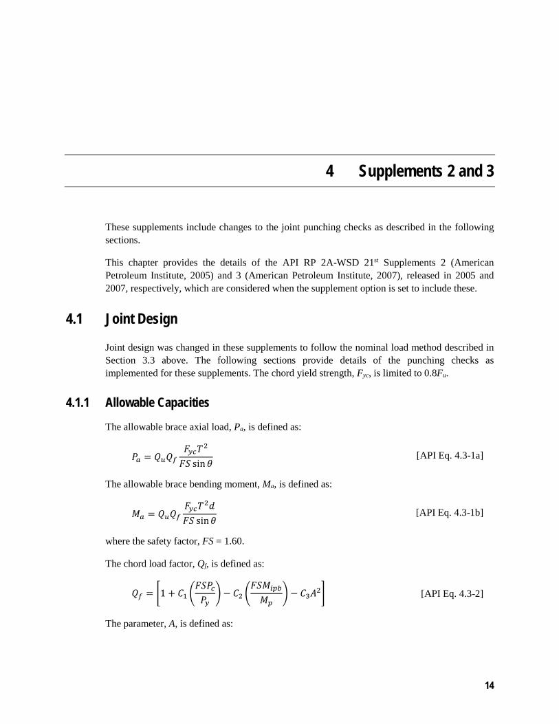
4 Supplements 2 and 3
These supplements include changes to the joint punching checks as described in the following sections.
This chapter provides the details of the API RP 2A-WSD 21st Supplements 2 (American Petroleum Institute, 2005) and 3 (American Petroleum Institute, 2007), released in 2005 and 2007, respectively, which are considered when the supplement option is set to include these.
4.1 Joint Design
Joint design was changed in these supplements to follow the nominal load method described in Section 3.3 above. The following sections provide details of the punching checks as implemented for these supplements. The chord yield strength, Fyc, is limited to 0.8Fu.
4.1.1 Allowable Capacities
The allowable brace axial load, Pa, is defined as:
𝑃𝑃𝑎𝑎 = 𝑄𝑄𝑢𝑢𝑄𝑄𝑓𝑓𝐹𝐹𝑦𝑦𝑐𝑐𝑇𝑇2
𝐹𝐹𝑆𝑆 sin𝜃𝜃 [API Eq. 4.3-1a]
The allowable brace bending moment, Ma, is defined as:
𝑀𝑀𝑎𝑎 = 𝑄𝑄𝑢𝑢𝑄𝑄𝑓𝑓𝐹𝐹𝑦𝑦𝑐𝑐𝑇𝑇2𝑑𝑑𝐹𝐹𝑆𝑆 sin𝜃𝜃
[API Eq. 4.3-1b]
where the safety factor, FS = 1.60.
The chord load factor, Qf, is defined as:
𝑄𝑄𝑓𝑓 = �1 + 𝐶𝐶1 �𝐹𝐹𝑆𝑆𝑃𝑃𝑐𝑐𝑃𝑃𝑦𝑦
� − 𝐶𝐶2 �𝐹𝐹𝑆𝑆𝑀𝑀𝑖𝑖𝑝𝑝𝑏𝑏
𝑀𝑀𝑝𝑝� − 𝐶𝐶3𝐴𝐴2� [API Eq. 4.3-2]
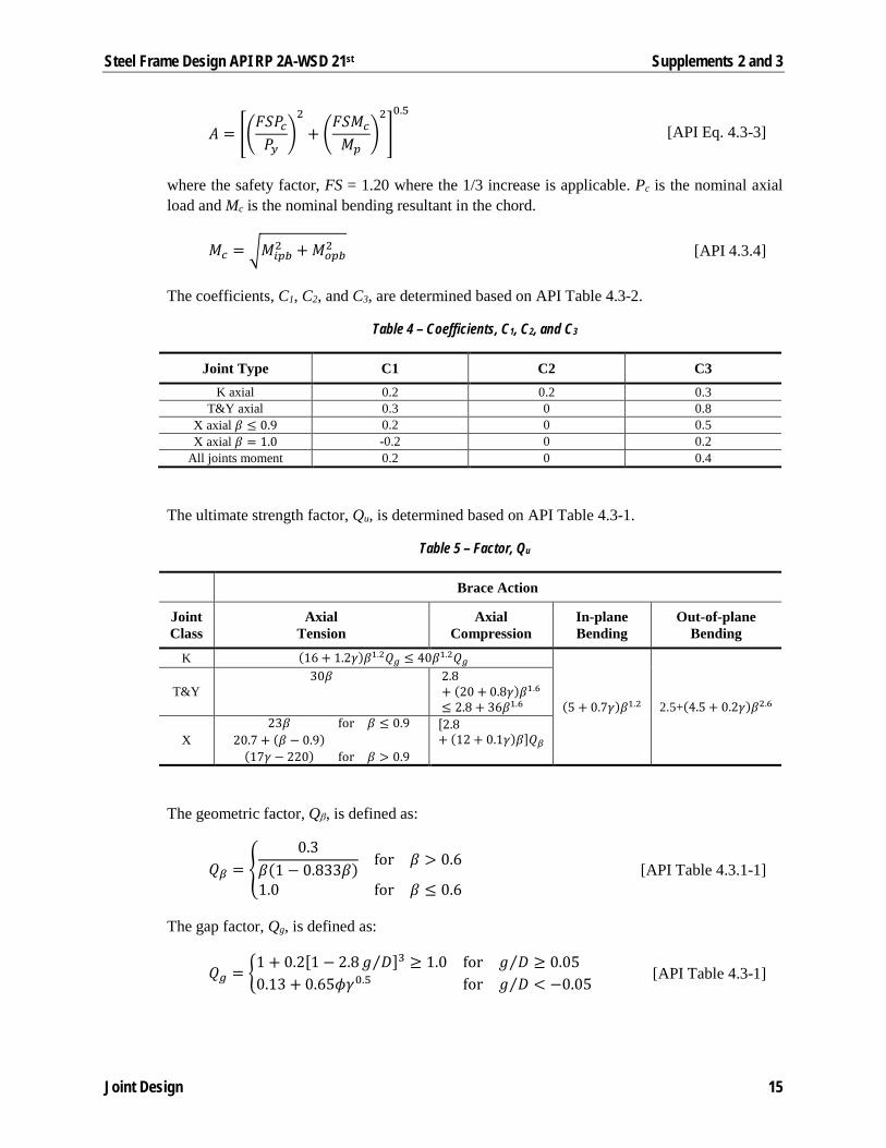
The parameter, A, is defined as:
14
Steel Frame Design API RP 2A-WSD 21st Supplements 2 and 3
𝐴𝐴 = ��𝐹𝐹𝑆𝑆𝑃𝑃𝑐𝑐𝑃𝑃𝑦𝑦
�2
+ �𝐹𝐹𝑆𝑆𝑀𝑀𝑐𝑐
𝑀𝑀𝑝𝑝�2
�0.5
[API Eq. 4.3-3]
where the safety factor, FS = 1.20 where the 1/3 increase is applicable. Pc is the nominal axial load and Mc is the nominal bending resultant in the chord.
𝑀𝑀𝑐𝑐 = �𝑀𝑀𝑖𝑖𝑝𝑝𝑏𝑏2 + 𝑀𝑀𝑜𝑜𝑝𝑝𝑏𝑏
2 [API 4.3.4]
The coefficients, C1, C2, and C3, are determined based on API Table 4.3-2.
Table 4 – Coefficients, C1, C2, and C3
Joint Type C1 C2 C3 K axial 0.2 0.2 0.3
T&Y axial 0.3 0 0.8 X axial 𝛽𝛽 ≤ 0.9 0.2 0 0.5 X axial 𝛽𝛽 = 1.0 -0.2 0 0.2
All joints moment 0.2 0 0.4
The ultimate strength factor, Qu, is determined based on API Table 4.3-1.
Table 5 – Factor, Qu
Brace Action
Joint Class
Axial Tension
Axial Compression
In-plane Bending
Out-of-plane Bending
K (16 + 1.2𝛾𝛾)𝛽𝛽1.2𝑄𝑄𝑔𝑔 ≤ 40𝛽𝛽1.2𝑄𝑄𝑔𝑔
(5 + 0.7𝛾𝛾)𝛽𝛽1.2 2.5+(4.5 + 0.2𝛾𝛾)𝛽𝛽2.6 T&Y
30𝛽𝛽 2.8+ (20 + 0.8𝛾𝛾)𝛽𝛽1.6
≤ 2.8 + 36𝛽𝛽1.6
X 23𝛽𝛽 for 𝛽𝛽 ≤ 0.9
20.7 + (𝛽𝛽 − 0.9)(17𝛾𝛾 − 220) for 𝛽𝛽 > 0.9
[2.8+ (12 + 0.1𝛾𝛾)𝛽𝛽]𝑄𝑄𝛽𝛽
The geometric factor, Qβ, is defined as:
𝑄𝑄𝛽𝛽 = �0.3
𝛽𝛽(1 − 0.833𝛽𝛽) for 𝛽𝛽 > 0.6
1.0 for 𝛽𝛽 ≤ 0.6 [API Table 4.3.1-1]
The gap factor, Qg, is defined as:
𝑄𝑄𝑔𝑔 = �1 + 0.2[1 − 2.8𝑔𝑔 𝐷𝐷⁄ ]3 ≥ 1.0 for 𝑔𝑔 𝐷𝐷⁄ ≥ 0.050.13 + 0.65𝜙𝜙𝛾𝛾0.5 for 𝑔𝑔 𝐷𝐷⁄ < −0.05
[API Table 4.3-1]
Joint Design 15

Steel Frame Design API RP 2A-WSD 21st Supplements 2 and 3
𝜙𝜙 = 𝑡𝑡 𝐹𝐹𝑦𝑦𝑏𝑏 �𝑇𝑇𝐹𝐹𝑦𝑦�⁄
4.1.2 Axial and Bending Check
Joints are checked for the following condition:
�𝑃𝑃𝑃𝑃𝑎𝑎�+ �
𝑀𝑀𝑀𝑀𝑎𝑎
�𝑖𝑖𝑝𝑝𝑏𝑏
2+ �
𝑀𝑀𝑀𝑀𝑎𝑎
�𝑜𝑜𝑝𝑝𝑏𝑏
≤ 1.0 [API Eq. 4.3-5]
The subscripts IPB and OPB correspond to in-plane bending and out-of-plane bending, respectively.
4.1.3 Overlapping Joints
Joints classified as K Overlap are checked for the following condition:
𝑃𝑃𝑝𝑝𝑥𝑥𝑝𝑝𝑃𝑃 ⊥
≤ 1.0 [API 4.3.2]
where Pper is the brace axial load component perpendicular to the chord, defined as:
𝑃𝑃𝑝𝑝𝑥𝑥𝑝𝑝 = 𝑃𝑃 sin𝜃𝜃
The allowable axial load perpendicular component is defined as:
𝑃𝑃 ⊥= �𝑃𝑃𝑎𝑎 sin𝜃𝜃𝐾𝐾1𝐾𝐾� + (2𝑣𝑣𝑤𝑤𝑎𝑎𝑡𝑡𝑤𝑤𝐾𝐾2) [API Eq. 4.3.2-2]
Joint Design 16
5 References
American Institute of Steel Construction. (1989). Manual of Steel Construction - Allowable Stress Design (9th ed.). Chicago, Illinois, USA: American Institute of Steel Construction.
American Petroleum Institute. (2000). Recommended Practice for Planning, Designing and Constructing Fixed Offshore Platforms - Working Stress Design (21st ed.). Washington, District of Columbia, USA: API Publishing Services.
American Petroleum Institute. (2005). RP 2A-WSD Errata and Supplement 2 (21st ed.). Washington, District of Columbia, USA: API Publishing Services.
American Petroleum Institute. (2007). RP 2A-WSD Errata and Supplement 3 (21st ed.). Washington, District of Columbia, USA: API Publishing Services.
17