API RECOMMENDED PRACTICE 2219 DRAFT …ballots.api.org/sfp/ballots/docs... · Safe Operation of...
52
Safe Operation of Vacuum Trucks Handling Flammable and Combustible Liquids in Petroleum Service API RECOMMENDED PRACTICE 2219 DRAFT FOURTH EDITION COMMITTEE DRAFT
Transcript of API RECOMMENDED PRACTICE 2219 DRAFT …ballots.api.org/sfp/ballots/docs... · Safe Operation of...

Safe Operation of Vacuum Trucks Handling Flammable and Combustible Liquids in Petroleum Service API RECOMMENDED PRACTICE 2219 DRAFT FOURTH EDITION
COMMITTEE DRAFT

2 API RECOMMENDED PRACTICE 2219
FOREWORD
This fourth edition of Safe Operation of Vacuum Trucks in Petroleum Service provides information concerning the safe operation of vacuum trucks engaged in all aspects of handling flammable and combustible liquids, associated waste water, produced water, sour water, basic sediment and water (BS&W), caustics, spent acids, or other fluids stemming from petroleum operations, products, powders and the hazard of dust explosions. This publication discusses the types of vacuum pumps and cargo tanks associated with vacuum truck operations, the common hazards associated with those vacuum truck operations and representative safe work practices and precautions to help prevent accidents and injuries. Appendix G provides brief descriptions of a variety of incidents involving vacuum trucks, including offloading into open areas. These may be useful in reviewing specific operating procedures or developing materials for safety meetings or pre-job briefings.
Vacuum truck personnel working in petroleum facilities shall be trained in the safe operation of the vacuum equipment, familiar with the hazards of the products being handled and aware of relevant facility permit requirements, safety procedures and emergency response requirements. It is the responsibility of the vacuum truck owner and operator to comply with (1) applicable federal, state and local regulations; (2) this recommended practice and (3) facility re-quirements regarding the safe operation of vacuum trucks; including, but not limited to, the following items:
* Construction, inspection, maintenance and certification of the vacuum tank.
* Selection and safe operation of the vacuum truck, vacuum pump, hoses and accessories.
* Regulatory requirements for safe highway operation of the truck.
* Proper transportation, handling and disposal of hazardous materials.
* Safe vacuum truck loading, unloading and transport operations within the facility.
* Training and qualification of operators and other assigned vacuum truck personnel.
Although the material contained in this document is intended to be consistent with regulatory requirements, API RP 2219 is not a compliance document. Each user or operator must ensure compliance with all applicable laws and regulations. The United States Department of Transportation (DOT) Code of Federal Regulations, 49 CFR, specifies the minimum requirements for the design, construction, maintenance, testing and operation of vehicles used for handling and transporting hazardous materials within the United States. Criteria for minimum training and qualifica-tions of drivers and operators are also found in 49 CFR. The Department of Labor, Occupational Safety and Health Administration's (OSHA) requirements for safety, health and hazard awareness applicable to operators and other personnel working with vacuum truck operations are found in the Code of Federal Regulations, 29 CFR 1910. U. S. Coast Guard regulations in 33 CFR 154 for bulk transfer of hazardous materials to and from vessels at marine facilities could include certain vacuum truck transfer operations.
The procedures contained herein are intended to apply to vacuum trucks, skids and trailers used in flammable and combustible liquid service. These requirements include, but are not limited to, 49 CFR parts 178.345 - 178.348 as well as DOT 407 and DOT 412 (formerly designated MC307 and MC312) cargo tank trailers used in vacuum and transfer operations for handling and transporting flammable and combustible liquids and corrosive materials.
Nothing contained in any API publication is to be construed as granting any right, by implication or otherwise, for the manufacture, sale, or use of any method, apparatus, or product covered by letters patent. Neither should anything contained in the publication be construed as insuring anyone against liability for infringement of letters patent.
COMMITTEE DRAFT

SAFE OPERATION OF VACUUM TRUCKS IN PETROLEUM SERVICE 3
Safe Operation of Vacuum Trucks In Petroleum Service
1 General
1.1 INTRODUCTION
Vacuum trucks are used in all segments of the petroleum industry with varied applications. Appropriate safe operating practices may vary because of different hazards associated with the materials to be moved and the facilities serviced. This recommended practice seeks to assist in the development and implementation of practical and safe operating practices that will help identify hazards and reduce risks.
1.2 SCOPE
The scope of this recommended practice includes the use of vacuum/pressure trucks, skids, portable tanks and trailers (herein referred to as vacuum trucks) to remove flammable and combustible liquids from tanks and equipment and to clean up liquid hydrocarbon spills. The scope includes movement of liquid mixtures (such as “produced water”, BS&W or tank bottoms) that may contain sufficient hydrocarbon material to present comparable hazards.
These safe practices also apply to the operation of portable vacuum tanks, skids and trailers typically used in emer-gency flammable and combustible liquid spill cleanup activities. While not included in the specific scope of this standard, Appendix F presents information related to pneumatic (air moving) trucks and hoppers, typically used in the petroleum industry for removal of dry materials such as catalysts, dusts, powders or, residue.
1.3 BASIC VACUUM OPERATIONS
The two basic types of vacuum truck operations are:
1. Vacuum loading and off-loading operations that eliminate or minimize the introduction of air into the system by:
a. Completely submerging the suction nozzle into the liquid during the transfer process and or
b. Directly connecting the transfer hose to the source or receiving tank, vessel or container, below the surface level of the liquid contained therein.
2. Vacuum truck operations that introduce air into the system during the transfer process, including:
a. Air conveying operations (Appendix F) involving the incidental removal of solid materials when the suction hose is either partially submerged or not submerged (or if submerged, when air is entrained or entrapped in the material) or the intentional removal of solids when used in a vacuum excavation system, or
b. Liquid transfer operations where the end of the hose is not directly connected to the source or receiving tank, container or vessel or the nozzle is not submerged into the liquid within the tank, container or vessel, and or
c. Vacuum truck operations involving spill cleanup of liquids where air enters the transfer hose as liquids are skimmed off the surface (water or land).
1.4 CONCEPT OF HAZARD VS. RISK
Hazards are conditions or properties of materials with the inherent ability to cause harm. Risk involves the potential for exposure to hazards that will result in harm or damage. For example, a hot surface or material can cause thermal skin burns or a corrosive acid can cause chemical skin burns, but these injuries can occur only if there is contact exposure to skin. A person working at an elevated height has “stored energy” and a fall from a height can cause injury—but there is no risk unless a person is working at heights and is thus exposed to the hazard. There is no risk when there is no potential for exposure.
COMMITTEE DRAFT

4 API RECOMMENDED PRACTICE 2219
Determining the level of risk for any activity involves understanding hazards and estimating the probability and severity of exposure that could lead to harm or damage. The preceding examples relate the consequences of hazard expo-sure, severity and probability to determine risks to people. The same principles can be applied to property risk. For instance, hydrocarbon vapors in a flammable mixture with air can ignite if exposed to a source of ignition resulting in a fire which could damage property as well as cause injury.
The U.S. Department of Transportation and the United Nations provide specific definitions and classifications for “Hazardous Materials”. These more general performance-based concepts are significant in order to understand the potential risk associated with vacuum truck operations.
1.5 JOB HAZARD ANALYSIS
Those in charge of vacuum truck operations can implement the principles of Hazard vs. Risk by conducting a job hazard safety analysis (JHSA) to assess hazards and risks associated with specific tasks. This review, sometimes also called a job safety analysis (JSA), helps identify hazards so that protective equipment, procedures and contin-gency plans can be put in place to mitigate risks associated with identified hazards.
Prior to engaging in jobsite vacuum truck operations, the relevant, written JHAs/JSAs should shall be reviewed by an entire crew including third party workers all relevant and responsible parties, to help everyone become familiar with the hazards, risks and exposure protection safeguards. Such JHAs/JSAs should be periodically reviewed so they remain current and can help to prevent incidents. (See OSHA Publication 3071, Job Hazard Analysis, or other JHA/JSA-related material from OSHA's web site.).
2 References
The most recent editions of each of the following standards, codes, and publications are referenced in this recom-mended practice as useful sources of additional information. Further information may be available from the cited Internet World Wide Web sites or references included in the Appendix A Bibliography.
API
RP 2003 Protection Against Ignitions Arising Out of Static, Lightning & Stray Currents.
ACGIH1
TLV’s® and BEIs® Based on Threshold Limit Values for Chemical Substances and Physical Agents and Biological Exposure Indices.
ASME2
ASME Boiler And Pressure Vessel Code Section VIII: Pressure Vessels—Division 1
ASME Boiler And Pressure Vessel Code Section XII: Rules for Construction and Continued Service of Transport Tanks.
NFPA3
NFPA 30 Flammable and Combustible Liquids Code.
NFPA 77 Recommended Practice on Static Electricity
1American Conference of Governmental Industrial Hygienists, 1330 Kemper Meadow Drive, Cincinnati, Ohio, 45240, www.acgih.org. 2American Society of Mechanical Engineers International, Three Park Avenue, New York, New York, 10016, www.asme.org, ASME Interna-tional [Publications], 22 Law Drive, Box 2900, Fairfield, New Jersey, 07007-2900. 3National Fire Protection Association, 1 Batterymarch Park, Quincy, Massachusetts, 02169, www.nfpa.org.
COMMITTEE DRAFT

SAFE OPERATION OF VACUUM TRUCKS IN PETROLEUM SERVICE 5
NFPA 326 Safeguarding of Tanks and Containers for Entry, Cleaning or Repair.
NFPA 650 Pneumatic Conveying Systems for Handling Combustible Particulate Solids.
NTTC4
Hazardous Materials Transportation—The Tank Truck Driver’s Guide.
NIOSH5
NIOSH Pocket Guide to Chemical Hazards.
Pratt, Thomas H. Electrostatic Ignitions of Fires and Explosions ISBN 0-8169-9948-1, AIChE CCPS
OSHA6
29 Code of Federal Regulations (CFR) Parts 1910.
1910.38 Employee Emergency Plans and Fire Prevention Plans
1910.1000 Subpart Z, Toxic and Hazardous Substances.
1910.132 Subpart I, Personal Protective Equipment.
1910.147 Control of Hazardous Energy (Lockout/Tagout).
1910.157 Fire Protection
1910.1200 Hazard Communication.
EPA7
40 CFR Protection of Environment.
DOT8
Federal Motor Carrier Safety Administration.
49 CFR Federal Motor Carrier Safety Regulations (Parts 100-199—especially noting Parts 178.345 – 178.348, 382, 383, 390-397, 407, and 412).
For specific requirements, carriers and shippers should consult the most current edition of 49 CFR Parts 100-185. Motor Carriers should also consult the Federal Motor Carrier Safety Regulations.
3 Definitions
The following definitions are applicable to this publication:
4The National Tank Truck Carriers, Inc., 2200 Mill Road, Alexandria, Virginia, 22314, www.tanktruck.net.org. 5National Institute for Occupational Safety and Health, 4676 Columbia Parkway, Cincinnati, Ohio, 45226, www.cdc.gov/niosh. 6U.S. Department of Labor, Occupational Safety and Health Administration, 200 Constitution Ave. N.W., Washington, D.C., 20210, www.osha.gov. 7U.S. Environmental Protection Agency, Ariel Rios Building, 1200 Pennsylvania Avenue, N.W., Washington, D.C., 20460, www.epa.gov. 8U.S. Department of Transportation, 400 7th Street, S.W., Washington, D.C., 20590, www.dot.gov.
COMMITTEE DRAFT

6 API RECOMMENDED PRACTICE 2219
3.1 atmospheric pressure: At sea level equals 14.7 psi (105 pascals) or 29.92 in Hg (760 mm Hg).
3.2 bonding: Providing electrical connections between isolated conductive parts of a system to equalize their electrical potential (voltage). A bond resistance as high as 1 megohm (106 ohm) is adequate for static dissipation. The targeted goal for bonding should be 0 ohm. For stray current protection, lightning protection, and other electrical systems, the bonding resistance needs to be significantly lower, no more than about 10 ohms.
3.3 BS&W: An abbreviation for “Basic Sediment and Water,” measured as a volume percentage from a liquid sample of the production stream. It includes free water, sediment and emulsion. BS&W may entrain flammable or combustible hydrocarbons or oily emulsions and then may release those hydrocarbons during service handling.
3.4 CHEMTREC: An acronym for “CHEMical TRansportation Emergency Center”, a system organized and coor-dinated by the American Chemistry Council to provide chemical-specific information to emergency responders around-the-clock.
3.5 cyclone separators: Devices that separate oil and water or solid materials from air by cyclone action.
3.6 exposure limit: The maximum concentration limits for toxic substances to which workers may be safely ex-posed for a prescribed time without protection ( e.g.., respiratory protection).
exposure limits are usually expressed in parts per million (volume) or milligrams per cubic meter, averaged for a prescribed time, e.g., 15 minutes, 8 hours. They may also be expressed as ceiling limits, which should not be exceeded. Material Safety Data Sheets (SDSs) available from employers, manufacturers or suppliers of the material should identify recommended exposure limits.
Permissible Exposure Limits (PELs) and Short-Term Exposure Limits (STELs) are regulatory exposure limits established in the Occupational Safety and Health Administration, U. S. Department of Labor regulations and are those found in the most current editions of OSHA 29 CFR 1910.1000 and chemical specific standards.
Threshold Limit Values® (TLVs®) are advisory exposure limit values published by the ACGIH and frequently provided as exposure guidance on SDSs.
3.7 grounding: Providing a means for electrical continuity so currents can dissipate to ground (earth). A resistance less than 1 megohm [<1x10⁶ ohm] is traditionally considered adequate for static dissipation. For other purposes, such as grounding electrical systems, lightning protection, etc., much lower resistances are needed. For new equipment a design target of 10 ohms is considered appropriate.
3.8 hazard: An inherent physical or chemical characteristic (flammability, toxicity, corrosivity, stored chemical, electrical, hydraulic, pressurized or mechanical energy) or condition that has the potential for causing death or damage to people, property, or the environment.
3.9 hazardous material: A term defined in U.S. DOT and EPA regulations or UN standards to identify materials which trigger specific mandatory or precautionary requirements (equipment, labeling, training, work practice etc).
3.10 job hazard analysis (JHA): A job hazard analysis is a technique that focuses on job tasks as a way to identify hazards so they can be eliminated or reduced to achieve an acceptable risk level. (see JSA)
3.11 3.10 job safety analysis (JSA): the systematic assessment of work activities and the workplace to identify potential hazards as a step to controlling possible risks. (see JHA)
3.12 3.11 liquid: Any material that has a fluidity greater than that of 300 penetration asphalt when tested in ac-cordance with ASTM D5 (NFPA 30).
combustible liquid is any liquid with a closed cup flash point at or above 100°F (37.8 oC). Combustible liquids at temperatures at or above their flash points are considered to be flammable.
Formatted: No bullets or numbering
COMMITTEE DRAFT

SAFE OPERATION OF VACUUM TRUCKS IN PETROLEUM SERVICE 7
flammable liquid is any liquid that has a closed cup flash point below 100°F(37.8 oC). (NFPA 30).
Renumber to end
3.13 pressure relief (safety) valve: A device that limits pressure to a preset level by exhausting surplus air, volume vapor or liquid., thereby ensuring that the permissible operating pressure is not exceeded; often abbreviated “PRV”.
3.14 risk: The probability for exposure to a hazard which could result in harm or damage.
3.15 risk assessment: The identification and analysis with judgments of probability and consequences, either qualitative or quantitative, of the likelihood and outcome of specific events or scenarios that can or could result in harm or damage.
3.16 risk-based analysis: A review of potential hazards and needs to eliminate or control such hazards based on a formalized risk assessment.
3.17 vacuum cargo tank: An enclosed space (tank) mounted on a vacuum truck (trailer or skid) from which most of the air (or gas) has been removed by a vacuum pump and where the remaining air (or gas) is maintained at a pressure below atmospheric.
3.18 vacuum, inches Hg: A measurement of the suction produced in a vacuum system where pressure is reduced relative to ambient atmospheric pressure. An inch of mercury (Hg) is a measure of vacuum that equals a solid column of water being lifted 13.6 in. or a “negative” pressure of 0.491 psig.
3.19 vacuum intake (suction air) filters: Filters mounted on the suction flange to prevent airborne solid materials from entering vacuum pump systems.
3.20 vacuum pump: A pump that is designed to remove air (or gas) in order to create a vacuum (pressure below atmospheric) within a vacuum cargo tank..
3.21 vacuum pump exhaust muffler (silencer): A device that reduces vacuum pump exhaust noise during suction and pressure operations.
3.22 vacuum pump oil separator: A small vessel that captures exhausted oil when the pump is operated under the vacuum mode. When a vacuum pump operates in the pressure mode, the oil separator acts as an oil bath filter to prevent airborne material from entering the vacuum pump.
3.24 vacuum pump relief valve: A device that reduces the potential for damage to the pump from overheating during long duration solid column loading or when there is insufficient cooling air or liquid. vacuum pump scrubbers (secondary shutoffs or moisture traps): Inlet devices that reduce vacuum pump damage and wear by trapping materials which may escape the vacuum pump’s primary shutoff trap during loading.
3.25 vacuum truck: A transportable vacuum system consisting of vacuum pump, vacuum cargo tank and associ-ated appurtenances and accessory equipment mounted on a motor vehicle.
4 Safe Handling of Hazardous Materials
4.1 HAZARDOUS MATERIALS AWARENESS
It is the responsibility of vacuum truck owners owner/operators to train vacuum truck operators in the proper transfer, handling and transportation of flammable and combustible liquids and hazardous materials.
4.1.1 Vacuum truck owners owners/operators shall assure that vacuum truck operators are aware of the physical and chemical characteristics of flammable, combustible, toxic and corrosive materials in accordance with applicable regulations. These regulations include, but are not limited to:
COMMITTEE DRAFT

8 API RECOMMENDED PRACTICE 2219
OSHA 29 CFR 1910.120 (Hazardous Waste Operations and Emergency Response);
OSHA 29 CFR 1910.1200 (Hazard Communication);
DOT 49 CFR Parts 106-7, 171 through 180 and 397 407 & DOT 412 (Transportation and Hazardous Materials Regulations).
Training materials addressing some of the regulatory requirements are available from the respective agencies’ web sites noted in Section 2 and in Appendix A Bibliography.
4.1.2 Care shall be taken to assure that the materials being loaded are compatible with materials previously loaded and that the mixing of these materials will not create hazards such as fire, explosion, heat, toxic gases or vapors. Unless the vacuum truck has been thoroughly cleaned and inspected, it should not be used to load materials which are not compatible with those previously handled. The same principles apply when materials are unloaded. Care shall be taken to assure that the materials being unloaded are compatible with the materials presently or previously con-tained in the receiving container. Moved from 4.6
4.1.3 Vacuum truck operators All parties involved with vacuum truck operations shall be aware that combustible liquids transferred at or above their flash point temperatures shall be handled as if they were flammable liquids. When transferring a combustible liquid which is within 15ºF of its flash point it shall be handled as a flammable liquid. This is especially significant when transferring combustible liquids into non-conductive tanks, containers or vessels.
4.1.4 Vacuum truck operators All parties involved with vacuum truck operations shall be aware that waste products from petroleum operations may contain trace amounts of flammable or combustible liquids and gases or other haz-ardous materials which may cause serious injury, illness or death, if not properly handled. In addition, vacuum truck operators shall be aware that when under vacuum, even trace amount of hydrocarbons and hydrogen sulfide gas can be easily separated and create flammable and/or toxic atmospheres.
4.1.5 Vacuum truck operators All parties involved with vacuum truck operations shall be aware that although BS&W may consist primarily of free water, sediment and/or emulsion, it may also entrain flammable or combustible hydro-carbons. Care should be exercised to understand the potential ignition and fire hazards associated with the material being handled. If condensate has been mixed with BS&W during the removal process, this can significantly increase the fire hazard. From a precautionary standpoint the mixture in the transport container should be treated as a flam-mable liquid absent positive proof to the contrary.
4.2 PRODUCT INFORMATION
4.2.1
The facility operator shall make Safety Data Sheets (SDS) and any other pertinent information about hazards and necessary precautions associated with the specific materials to be handled, available to the vacuum truck operator prior to the job starting. The NIOSH Pocket Guide to Chemical Hazards is a useful resource to properties of materials, their hazards and some exposure limits.
Material sSafety data sheets should provide correct information on materials originally stored in tanks or vessels, but might not accurately reflect the hazards when the material is co-mingled with other chemicals, waste products, tank bottoms, contaminated catalysts, spent acids or other materials that are being transferred. The vacuum truck operator shall be provided with available and relevant information regarding the properties chemical makeup of the material to be handled.
Formatted: Font: Bold
COMMITTEE DRAFT

SAFE OPERATION OF VACUUM TRUCKS IN PETROLEUM SERVICE 9
4.2.2 In emergency situations such as spill response and cleanup, product safety information may be obtained from sources other than the manufacturer or shipper, including, but not limited to: Chemtrec, Department of Transportation, state and local emergency response agencies, U.S. Coast Guard, fire departments, etc.
4.3 PERSONAL PROTECTIVE EQUIPMENT
Both good practice and OSHA regulations (1910.132) require a hazard determination to evaluate the need for per-sonal protective equipment (PPE). When necessary, appropriate respiratory protection, chemical protective equip-ment, goggles, gloves, boots and other required PPE shall be provided by vacuum truck owners and used by vacuum truck operators for protection from exposure to the material being handled. It is the responsibility of vacuum truck owners to assure that vacuum truck operators are trained and qualified.
4.3.1 Vacuum truck operators shall know which type of personal protective equipment to use under various condi-tions of potential exposure or known exposure. Personal protective equipment may be required to provide body, eye and respiratory system protection.
4.3.2 Vacuum truck operators shall be aware of applicable OSHA personal protective equipment requirements in-cluding, but not limited to 29 CFR 1010.132, Subpart I Personal Protective Equipment and PPE elements in regula-tions listed in Section 4.4. Vacuum truck operators shall also be aware of the facility’s industrial hygiene and safety requirements relevant to the vacuum truck operations being conducted.
4.4 HAZARDOUS MATERIALS REGULATIONS
Vacuum truck owners shall assure that vacuum truck operators are trained, knowledgeable of and comply with ap-plicable federal, state and local regulations including, but not limited to, the following:
• 29 CFR 1910.1000 - 1096, Subpart Z Toxic and Hazardous Substances (including Benzene at 1910.1028)
• 29 CFR 1910.120, Hazardous Waste Operations and Emergency Response
• 29 CFR 1910. 1200, Hazard Communications
• 40 CFR 263, Protection of Environment
• 40 CFR 311.1, Worker Protection Standards for Hazardous Waste Operations
• 49 CFR, Parts 172, 173, 178-179, 382, 383 and 390-397, Motor Carrier Safety
4.5 EMERGENCY RESPONSE
Vacuum truck owners shall assure that vacuum truck operators are trained or educated in appropriate emergency response actions and regulatory reporting requirements in the event of a fire, spill, release or other emergency.
4.5.1 Vacuum truck operators shall be trained in the use of portable fire extinguishers. Portable fire extinguishers should shall be provided with the vacuum truck and maintained in accordance with applicable regulatory requirements such as 29 CFR 1910.157, Fire Protection and also be available at the work site..
4.5.2 Vacuum truck owners shall prepare an emergency response plan conforming to OSHA requirements at 29 CFR 1910.38 (Employee Emergency Plans and Fire Prevention Plans), and shall train all operators in the use of that plan.
4.5.2.1 Vacuum truck operators shall be aware of facility emergency reporting and response procedures.
COMMITTEE DRAFT

10 API RECOMMENDED PRACTICE 2219
5 Safe Vacuum Truck Operations
5.1 GENERAL
Vacuum truck owners are responsible to comply with federal, state and local regulations regarding the construction, maintenance and operation of vacuum trucks and to assure that operators and other assigned personnel are trained and qualified for their assigned work.
5.1.1 Hazards of Vacuum Truck Operations
Although using vacuum trucks provides a fast, safe and efficient method of cleaning up spills and removing liquids, tank bottoms, solid materials and waste from tanks and vessels in petroleum facilities, incidents have occurred during vacuum truck operations. See Appendix G for specific examples.
Vacuum truck owners and operators, as well as facility personnel, should be aware of the numerous potential hazards associated with vacuum truck operations in petroleum facilities. Some (but not all) of the potential hazards associated with vacuum truck operations are listed below.
5.1.1.1 Sources of ignition include vacuum truck engine and exhaust heat, pump overheating, faulty or improper electrical devices, static electricity discharges, outside ignition sources such as smoking, motor vehicles, stationary engines, etc.
5.1.1.2 Potential hazards include spills, flammable atmosphere within and around the vacuum truck, cargo tank or source container, hose failures and discharges of flammable vapors to the atmosphere from the vacuum truck or the source or receiving container and worker exposures to toxic vapors, liquids or solids.
5.1.1.3 Consideration for potential hazards associated with the surrounding area and atmospheric conditions during the vacuum truck operations. Discharged vapors can exceed Permissible Exposure Limits (PELs) for exposed workers. Vapors can collect in low spots, particularly during atmospheric inversions with high humidity and no wind. Vapors should not be discharged onto roadways or other areas where sources of ignition may occur.
5.1.1.4 Unloading materials containing flammable components to open pads or pits can release vapors resulting in a fire, explosion or substance exposure hazard.
5.1.1.5 Toxic vapors that are below hazardous concentrations prior to handling may become concentrated and thereby hazardous at or near the discharge port of the vacuum pump.
5.1.1.6 From a precautionary standpoint the mixture in the transport container should be treated as a flammable liquid absent positive proof to the contrary
5.1.1.7 Additional hazards include those typical to tank truck operations such as slips and falls, spills and releases, fires and explosions, and accidents within the facility or vehicle incidents on the highway.
5.1.2 Inspection Requirements
Before beginning operations, vacuum truck operators shall obtain any required permits and inspect vacuum trucks, equipment and loading/off-loading sites to assure safe operations. See Appendices C and D for inspection, mainte-nance and operating requirements.
5.2 ATMOSPHERIC TESTING
The areas in which vacuum trucks are to operate must shall be free of hydrocarbon vapors in the flammable range. The areas where the vacuum truck operator and others work without respirators must also be at or below air-contaminant PELs or STELs. Therefore, testing shall be conducted when appropriate. Where required by facility procedures, permits shall be issued prior to the start of any vacuum truck operations.
COMMITTEE DRAFT

SAFE OPERATION OF VACUUM TRUCKS IN PETROLEUM SERVICE 11
If there is any question whether the area is free of flammable vapors or toxic gases Atmospheric testing shall be performed by a qualified person using properly calibrated and adjusted combustible gas indicators, appropriate toxic gas testers or hydrocarbon vapor analyzers. While combustible gas indicators can provide information indicating that substance levels are too high for personnel exposure they are not sensitive enough to provide valid information that air concentrations are below personal exposure limits. The atmosphere shall be continuously monitored for sources of flammable gas or vapor to determine if a flammable atmosphere exists. The continuous air monitoring will provide vacuum truck operator an early warning of conditions at the location. Testing shall be conducted before any opera-tion is started, and if necessary, during operations, including, but not limited to, the following:
5.2.1 When operations in the area are subject to change such as automatic pump start-up or product receipt into or transfer out of a tank located in the vicinity of the transfer operations. In these situations, consideration should be given to use of lockout/tagout procedures on equipment that could create a hazardous condition or where required by reg-ulation (see 29 CFR 1910.147).
5.2.2 When off-loading a waste container where pockets or layers of hydrocarbon, hydrogen sulfide, water and other hazardous materials may exist.
5.2.3 When atmospheric condition changes, such as wind direction, storm, etc. affect the operation.
5.2.4 When an emergency situation, such as a product or vapor release, occurs within the facility that may affect atmospheric conditions in the transfer area.
Vacuum trucks shall be not be allowed inside diked areas around petroleum storage tanks, other production units or operations vessels until the areas have been tested for hydrocarbon vapors by qualified persons, determined to be safe and entry authorized and/or a permit issued if required by facility procedures.
5.3 CONDUCTIVE AND NON-CONDUCTIVE HOSE
Vacuum truck operators may use either conductive or nonconductive hose, it is sometimes difficult to distinguish between the two dependent on the material being transferred and subject to Section 5.3.1 and 5.3.2. Petroleum industry experience indicates that electrostatic ignitions can present a significant hazard when using non-conductive transfer hose. Any isolated (unbonded) conductive object may accumulate a charge and provide a spark gap. Even when using conductive hose, vacuum truck operators should shall both ground and bond and ground their trucks to reduce the possibility of electrostatic discharges. See Section 5.4.
5.3.1 Conductive Hose
Vacuum hoses constructed of conductive material or thick walled hoses with imbedded conductive wiring shall be used when transferring flammable and combustible liquids. when the potential for a flammable atmosphere exists where the vacuum truck is operating. Conductive hose shall provide suitable electrical resistivity less than or equal to 1 megohm (1 x 10⁶ohm) per 100 ft (as determined by the hose manufacturer).
Periodic inspection and testing of hoses will enable identification and removal from service of hoses which have lost their conductivity. The hose manufacturer should be consulted for testing procedures and inspection frequency. Documentation will allow tracking of condition.
Thin walled, metallic spiral wound conductive hoses should not be used due to the potential for electrical discharge through the thin plastic that covers the metal spiral.
All hoses, both liquid and exhaust, must be easily identified as conductive by permanent, stainless steel banding. The hose banding must include an identifying serial number, manufacturer name and most recent certification date.
All vacuum truck hoses must be tested annually, certified, and steel banded or tagged with certification date. The vacuum truck service provider is responsible for the compliance testing, tracking, rejections and documentation of all hoses transported on the vacuum trucks or supplied by the vacuum truck service provider. Hose testing records must be maintained for at least 1 year. Hoses provided by parties other than the vacuum truck service provider shall be
COMMITTEE DRAFT

12 API RECOMMENDED PRACTICE 2219
responsible for compliance testing, tracking and documentation of all hoses provided (typically used at frequently serviced, stationary sites).
In addition to the annual certification testing specified above, all hoses must be visually inspected prior to each job and a minimum of once each shift for longer duration jobs by the truck operator. Any hose that does not meet the re-quirements must be rejected and the supervisor notified. Inspect all hoses for the following:
- Check for wear points exposing braids and kinks on the hose.
- Test continuity of all hoses. Recommended guidance considers up to 106 ohms/100 ft. (1 megohm/100 ft) to be sufficient to allow for dissipation of static electricity (Typical measurements are well below 106 ohms, so 10,000 ohms per hose segment has been selected as a practical maximum resistance and providing an adequate conservative contingency).
- Check for abnormal wear or damage to metal hose ends, gasket, and confirm locking device functions properly.
- Hose must be fixed with permanent identification tag with the date indicating it has been checked within the required inspection period and include a unique number for tracking the inspections.
5.3.2 Non-Conductive Hose
Non-conductive hose shall not be used in transferring either flammable or combustible liquids. Nonconductive hose can accumulate static electricity and act as an ignition source by discharging a static spark if a conductor touches or comes close to a grounded object. Nonconductive hose shall not be used to discharge flammable liquids into open areas such as pits or open tanks, or where any source of flammable vapors may be present near the open end of the hose.
Although not recommended, a facility may permit the use of non-conductive hose to transfer combustible liquids where there is no potential for a flammable atmosphere in the area. If use of non-conductive hose is permitted, all exposed connectors (such as tubes, metal hose flanges, couplings, fittings and suction nozzles) shall be constructed of conductive materials and each one shall be individually bonded and grounded to the vacuum truck and the source or receiving vessel. As indicated in 5.3.1 conductive hoses shall be used where there is potential for a flammable atmosphere.
5.3.3 Fittings
All Cam-lock type fittings must be securable by locking handles, arms wired closed (through rings) or tape, (e.g. Velcro strap) to prevent inadvertent release. Cam-lock metallurgy must be compatible with and suitable for the material being transferred.
Any hose end connection appurtenance (e.g. stingers, strainers, duck bills, etc.) used during a vacuum truck operation must be made of conductive material, approved for use at the respective site, and be continuity tested as bonded with the conductive hose prior to each use. Users may elect to weld bonding tabs to these appurtenances to allow for clamping of bonding cables.
The use of plastic non-conductive dip pipes, funnels and intermediate collection pans (including kiddie pools) for spill response or draining activities is prohibited. Only properly grounded conductive pipes, funnels and containers shall be used for intermediate collection of flammable or combustible material to be vacuumed."
COMMITTEE DRAFT

SAFE OPERATION OF VACUUM TRUCKS IN PETROLEUM SERVICE 13
5.4 BONDING AND GROUNDING
Bonding and grounding provide controls to help eliminate static electricity. Bonding connects two or more conductive objects using a conductor such as a bronze or copper wire. This equalizes the potential charge so there is no voltage difference between them. Bonding can also connect parts of equipment or containers that are electrically separated (for example by gaskets or non-conductive spacers). Bonding equalizes but does not eliminate the static charge. Grounding connects one or more conductive objects directly to the earth. Unlike bonding, proper grounding does drain static charges. The length of time for the charge to drain varies as a function of the charged object. A desig-nated, proven ground source is preferred should be used.
Under no circumstances shall should the ground wire on a piece of electrical equipment be used as a ground connection for a vacuum truck. It could introduce hazardous stray currents due to electrical faults or system grounds.
Connectors for bonding and grounding, such as copper wire and clamps, must provide a good conductive path. To ensure this:
• remove all dirt, paint, rust, or corrosion from areas where connections are to be made; and
• use connectors that are rated for static electrical service that are strong enough for the job; and
• use flexible connectors where there is vibration or continuous movement; and
• connect metal to metal.
Because electrical currents (amperage) associated with static charge accumulations are low, bonding and grounding cables for draining static charges are sized for strength, flexibility and durability. Typical cables are woven or braided metallic strands generally no larger than #6 AWG. Fixed mechanical connections are preferred for permanent bonding connections with strong alligator or special purpose C-clamps used for temporary bonding and grounding. These often have pointed contacts to displace rust or paint. For more information, consult your specialist safety equipment sup-plier.
The complete vacuum transfer system needs to be grounded (earthed) to dissipate stray currents to earth and also bonded so that there is a continuous conductive path from the vacuum truck through the hose and nozzle to the tank or source container. The grounding/earthing and bonding cables shall be connected from the loading system to the truck before any operation is carried out. This system should provide an electrical contact resistance of less than 10 ohms for bonding and 1 megaohm for grounding between the truck and a grounded structure. A screw down C-type clamp provides a metal to metal connection that is less likely to be accidentally knocked loose.
Testing of Bonding and Grounding static lines. All bonding and grounding static lines will be attached and tested before starting the loading or off-loading process. Testing will include (a) the testing of static lines at the point it is connected to the retractable reel, and (b) the testing of the retractable reel at the point it is connected to the vacuum truck.
A bond resistance as high as 1 megohm (106 ohm) is adequate for static dissipation. For stray current protection, lightning protection, and other electrical systems, the bonding resistance needs to be significantly lower, no more than about 10 ohms.
A resistance less than 1 megohm [<1x10⁶ ohm ] is traditionally considered adequate for static dissipation. For other purposes, such as grounding electrical systems, lightning protection, etc., much lower resistances are needed. For new equipment a design target of 10 ohms is considered appropriate.
The following should be noted:
COMMITTEE DRAFT

14 API RECOMMENDED PRACTICE 2219
a. Unbonded conductive objects, such as nozzles, can accumulate high electrostatic charges during transfer opera-tions.
b. Mixed lengths of conductive and non-conductive hose shall not be used as they can accumulate high electrostatic charges during transfer operations.
c. Bonds and grounds should not be disconnected until all transfer operations have ceased and the suction nozzle, hose or tube is withdrawn from the source or receiving tank or container.
d. The vacuum truck owner shall establish a schedule for inspecting and testing the electrical continuity of grounding and bonding cables and hoses provided with the vacuum truck (depending on the use and condition of the cables).
5.4.1 Bonding
Bonding prevents the formation of different electrostatic potentials between vacuum trucks and pumps and the source or receiving tank, container or vessel and intermediate container or vessel by bringing all parts of the connected system to an equivalent electrical potential. This reduces the likelihood of a spark being created in the vicinity of flammable vapors when the suction nozzle or discharge hose is removed from the source or discharge container and/or disconnected from the vacuum trucks, or when any conductive connectors are disconnected. See API RP 2003 for additional information on static electricity.
5.4.1.1 Whenever liquids or materials are transferred into or from a tank, vessel or container (other than a surface spill), a bonding cable shall be connected from the vacuum truck to the source or receiving container. To assure proper bonding, the continuity should be verified with an ohmmeter following connection and prior to the start of operations. Prior to beginning transfer to assure proper bonding the continuity shall be verified with an ohmmeter.
Exception: If both the vacuum truck and the source or receiving container are suitably grounded, and if the transfer is through tight, metal-to-metal connections, using conductive hose, fittings, tubes and suction nozzles, without any use of non-conductive gaskets, bonding may be achieved without a need to use separate bonding cables. Bonding should be verified using an ohmmeter or other device specifically designed to confirm an effective bond.
5.4.1.2 When liquid is transferred to or from a non-conductive or lined container (that is not suitably grounded), bonding may be achieved by inserting an uncoated, corrosion-free metallic rod (or similar approved conductor) to the bottom of the fluid in the container. The rod is connected to the vacuum truck with a proper bonding cable and the bonding verified using an ohmmeter or other device specifically designed to confirm an effective bond.
5.4.2 Grounding
Before starting transfer operations, vacuum trucks should be grounded directly to the earth or bonded to another object that is inherently grounded (due to proper contact with the earth) such as a large storage tank or underground piping. Grounding minimizes the electrical potential differences between objects and the earth in order to prevent a static charge. Grounding brings all parts of any system to zero electrical potential by allowing electrical currents to dissipate to earth (ground).
Retractable reels used for vacuum truck grounding cables shall be designed to provide electrical continuity between the grounding clamp or clip at the end of the cable and the vacuum truck, regardless of the amount of cable extended. A safe and proper ground to earth may be achieved by connection to any properly grounded object, including, but not limited to, any one or more of the following examples:
• The metal frame of a building, tank or equipment which is grounded.
• An existing facility grounding system, such as that installed at a loading rack.
COMMITTEE DRAFT

SAFE OPERATION OF VACUUM TRUCKS IN PETROLEUM SERVICE 15
• Fire hydrants, metal light posts or underground metal piping with at least 10 ft of contact with the earth. In some cases fence posts, metal stakes etc. may not provide adequate grounding because of insufficient depth or soil conditions, and flange gaskets can isolate piping from a grounding connection. Note: not all fire main steel pipe underground; check before using as a ground connection. Note: not all fire mains consist of steel pipe underground, some use HDPE; check before using as a ground connection.
• A corrosion-free metal ground rod of suitable length and diameter (approximately 9 ft long and 5/8 in. diameter), driven 8 ft into the earth (or to the water table, if less). Resistance of the ground will vary depending on both the type of soil and the amount of moisture present in the soil.
• A metal plate of suitable size and thickness (approximately 2 ft2 in area and 1/4 in. thick, if steel or 5/8 in., if copper) buried in the ground to a depth of at least 2 1/2 ft.
5.5 VACUUM PUMPS AND BLOWERS
Under normal conditions, the absence of oxygen minimizes the risk of ignition in a vacuum tank. However, operating rotary lobe blowers and vacuum pumps at high speeds creates high air movement and high vacuum levels. This results in high discharge air temperatures and high discharge vapor concentrations that can present a potentially ignitable condition.
5.6 VACUUM EXHAUST VENTING AND VAPOR RECOVERY
When flammable, combustible or toxic liquids are transferred by vacuum pumps, product vapors may be discharged into the atmosphere in full concentration through unrestricted exhausts or in lesser amounts if filtered or separated prior to exhaust. The potential exists for these discharged vapors to form flammable mixtures with air and contact the vacuum truck’s engine, hot exhaust pipe or outside sources of ignition. Also, hydrocarbon vapors may be aspirated by the vacuum truck’s diesel engine, causing “dieseling” (a condition where the engine continues to run after being turned off) or “run away” (a condition which can lead to overspeed and catastrophic engine failure). For more information on controls see Appendix B.4.1. Where there is the potential for vapors to form flammable mixtures with air from the exhaust vents, consider the use of continuous LEL monitoring.
In addition, toxic vapors well below flammable concentrations may still expose the vacuum truck operator or others at levels above PELs, STELs or TLVs since one percent Lower Explosive Limit equals 10,000 ppm. Vacuum pump exhausts should be vented to an area free of personnel and isolated by barricades or appropriate respirators should be worn, unless atmospheric testing for toxic vapors confirms respirators are not required.
Potential sources of vacuum pump vapors can be unique to the type of vacuum pump used:
a. When liquid ring vacuum pumps are used, flammable vapors may accumulate on top of the discharge separator. The vapors discharged by liquid ring pumps may also be saturated with water (or other service liquid). In addition, if the temperature of the service liquid is higher than the temperature of the incoming vapor, evaporation will occur at the suction port.
b. The air discharged from rotary vane pumps may be saturated with lubricating oil or vapors.
c. Rotary lobe blowers operating at high airflow rates and vacuums may atomize liquid hydrocarbons that are sub-sequently discharged through the exhaust.
Vacuum pump vapors can be controlled through safe vapor recovery and safe venting methods. In areas where vapor recovery is mandated or desired, exhausted vapors should be directed to a vapor recovery unit. If vapors are vented to atmosphere during loading and off-loading, the travel direction, atmospheric and wind conditions, topography and all potential sources of ignition must be considered and appropriate protective measures put into place prior to starting operations. Since vacuum truck engines (and auxiliary engines) are ignition sources, vacuum trucks should be oper-ated upwind of any transfer point and outside the path of potential vapor travel.
COMMITTEE DRAFT

16 API RECOMMENDED PRACTICE 2219
5.6.1 Venting
A number of methods can be used by vacuum truck operators to safely vent vacuum pump exhaust vapors, including, but not limited to, the following:
a. Operators can prevent diesel engine acceleration, or “runaway,” by locating the vacuum truck upwind of vapor sources and by extending the vacuum pump discharge away from the diesel engine air intake.
b. Vapors may be returned to the source container using conductive hose and closed connections.
c. Vapors may be vented into the atmosphere to a safe location using a safety venturi, mixing vapors with air, so the vapors are discharged at a diluted rate during most of the transfer operation. Caution is required as vapors may reach the flammable range during low flow periods (such as the final few minutes of loading) or under other conditions.
d. Vacuum truck operators may provide vertical exhaust stacks, extending approximately 12 ft above the vacuum truck (or higher if necessary), to dissipate the vapors before they reach ignition sources, personnel or other potential hazards.
e. Vacuum truck operators may attach a length of exhaust hose to the vacuum exhaust that is sufficiently long enough to reach an area that is free from potential hazards, sources of ignition and personnel. The hose should be preferably extended 50 ft. downwind of the truck and away from the source of the liquid.
5.6.2 Vapor Recovery
In order to prevent ignition from occurring, an analysis should be conducted prior to each specific use of a vapor re-covery system to determine the potential hazards. Appropriate safety measures include, but are not limited to, the following:
a. Some vapor recovery units and vapor control systems develop high operating temperatures and may therefore become ignition sources. An appropriate in-line flame arrestor, placed in the vapor recovery line between the vacuum truck discharge exhaust and close to the vapor recovery unit, will mitigate or prevent flashback from the vapor re-covery unit into the vacuum truck.
b. Vacuum exhaust vapors shall be vented to vapor recovery units using conductive hose with closed connections and appropriate bonding and grounding.
c. Carbon adsorption canisters connected to the vacuum discharge exhaust may become saturated by lubricating oil or contaminated by vacuum exhaust vapors, resulting in spontaneous combustion. An appropriate flame arrestor shall be placed in the vapor recovery line between the vacuum discharge exhaust and close to the canister, to prevent flashback into the vacuum truck cargo tank.
d. Vacuum truck operators shall assure that carbon adsorption canisters are properly bonded to the vacuum units to prevent buildup of static charges that may create sources of ignition.
e. Vacuum truck operators shall assure that vapor recovery units, control systems, vapor lines and canisters are properly rated to handle the amount of flow developed by the vacuum pump so as to minimize back pressure.
See API RP 2028 Flame Arresters in Piping Systems for additional guidance.
5.7 TRANSFER OPERATIONS
Vacuum truck operators shall be aware of the hazards involved in petroleum product and associated materials transfer operations. They shall be trained in safe product transfer practices and follow company and facility safety procedures when loading and off-loading vacuum trucks.
COMMITTEE DRAFT

SAFE OPERATION OF VACUUM TRUCKS IN PETROLEUM SERVICE 17
5.7.1 Loading
The loading rate is governed by the size and length of the hose and the vacuum level in the truck. Once an appro-priately high vacuum level is reached in the cargo tank and the hose is connected to the source container or sub-merged into the product, the hydrocarbon liquid is loaded as a solid column with very little air introduced in the system. When following this procedure, the volume of air exhausted from the vacuum pump is usually very small, especially at high vacuum levels. This reduces the potential for a vapor-air mixture in the flammable range. See Appendix D Safe Vacuum Truck Operations for loading procedures.
5.7.1.1 Air Entrainment
During loading, if the hose or suction nozzle is not completely submerged in the liquid, or not directly connected to the source container below the liquid level, air is introduced into the product stream. Depending on the flow rate and the hose diameter, the product may atomize, become suspended in the airflow and not be deposited in the vacuum tank. When this occurs, the vacuum level inside the truck decreases and large amounts of vapor and air are exhausted into the atmosphere.
5.7.1.2 Vacuum truck operators shall follow safe operating procedures to prevent or minimize the amount of air introduced into the vacuum truck cargo tank during transfer from source containers. This is particularly important at the beginning and the end of product transfer operations when the suction nozzle or the end of the hose may not be completely submerged in the liquid.
5.7.1.3 Vacuum truck operators or whoever is in control of the nozzle shall take care to minimize air intake when skimming product (for example, off of the surface of water or from spills on land) and when the suction nozzle or the end of the hose may not be completely submerged.
5.7.2 Off-Loading
The method chosen for off-loading should include a review of the potential hazards of the material (flammability, corrosivity and/or toxicity) and ensure that where necessary, the procedures properly control vapors. Where flam-mable materials are involved, closed systems or appropriate ventilation may be necessary. Elimination of potential ignition sources can be achieved by proper grounding, bonding, use of intrinsically safe equipment and shutting down equipment not in use (such as truck engines when gravity draining). As indicated in D.4, wind direction should be considered when placing trucks for offloading and control of vapors released by the off-loading process. Extension vent hoses may be necessary as mentioned in 5.6 and in D.4.1.3.b.
5.7.2.1 The three methods of off-loading vacuum trucks are gravity, pressure and pump-off. Flammable liquids and other hazardous materials should be off-loaded by gravity or inert gas (typically nitrogen) pressure blanket, in order to minimize the amount of air that mixes with the flammable vapors and to prevent the formation of a pressurized flammable vapor-air mixture inside the vacuum cargo tank. Pressure off-loading with an inert gas pressure blanket may also be used for off-loading products that react with air or moisture. See Appendix D.4 for more detailed examples off-loading procedures.
1. Gravity Method—Gravity off-loading is safer, easier and less expensive and is therefore used more frequently than pump-off or pressure off-loading. The gravity method is preferred for off-loading flammable liquids and haz-ardous materials, as well as for non-flammable and combustible materials.
2. Pressure Method—When pressure off-loading with air or inert gas blanket, the pressure must not be allowed to exceed the pressure relief valve setting, or if such setting is not known, the maximum allowable working pressure as indicated by the vacuum cargo tank data plate. Outside sources of compressed air, such as provided by an air compressor or air tanks, should not be used to pressurize vacuum truck cargo tanks for off-loading. Pressure off-loading with air is accomplished by reversing the vacuum pump on the truck. Pressure off-loading with air is typically used only when products are not considered to be flammable, hazardous or toxic.
Note: When vacuum pumps are reversed to off-load combustible products, this reverse action may heat combustible liquid hydrocarbons to temperatures above their flash points and they must then be treated as flammable liquids.
COMMITTEE DRAFT

18 API RECOMMENDED PRACTICE 2219
3. Pump-off Method—Auxiliary (external) gear or rotary transfer pumps may be used to off-load heavy, viscous products which are difficult to remove by pressure or gravity.
5.7.2.2 Prior to off-loading, vacuum truck operators shall determine or verify that the receiving container has suffi-cient available capacity to contain the amount of product to be transferred and the pressure must not be allowed to exceed the pressure relief valve setting of the receiving tank.
5.7.2.3 During vacuum cargo tank off-loading, vacuum truck operators shall minimize the amount of air introduced into the receiving container by directly connecting the hose to the receiving container or submerging the end of the transfer hose into the product. This will prevent free-fall of liquids and avoid or minimize splash off-loading to prevent static build up and excessive vapors. If the hose is connected directly to the receiving container, vacuum truck oper-ators shall maintain low flow until the intake is completely submerged.
5.7.3 On-Site Transfer
Vacuum trucks may be used to transfer material from one tank or vessel to another without leaving the site. This may be in traditional loading at one point and unloading at another. Alternatively, the truck’s equipment may be used as a “portable pump” with direct connection through the truck from one tank or vessel to another. Operators should im-plement the applicable precautions listed in the sections above for loading (5.7.1), air entrainment (5.7.1.1, 5.7.1.2 and 5.7.1.3) and off-loading (5.7.2). Maintaining static electricity safeguards is especially important where the truck is used as a pump with hose connection between vessels. A conductive path from one vessel to the other will help equalize charges.
5.7.4 Non-Conductive Equipment
Vacuum truck operators shall be aware of the following precautions regarding the use of non-conductive equipment. These precautions are necessary to reduce the potential for ignition during vacuum truck operations because static charges can accumulate with this type of equipment and create a source of ignition.
Some synthetic fabrics, including some Flame Resistant Clothing (FRC), can accumulate static charges. See API RP 2003 for details on clothing.
The use of non-conductive transfer items such as plastic funnels, strainers, etc. shall be prohibited. All equipment used in the transfer shall be made of conductive materials and be properly bonded. Bonding is not effective on non-conductive objects. The use of non-conductive containers, such as plastic pails, as intermediate collection vessels during vacuum truck operations shall be prohibited. Only conductive con-tainers shall be used and vacuum truck operators shall assure that these are bonded to the transfer hoses, connectors, nozzles and the source or receiving tank, vessel or container.
The use of tools which provide less conductive or more resistive properties such as aluminum or brass should be
considered when performing operation in the immediate area of flammable atmospheric conditions.
5.8 OVER-PRESSURE AND UNDER-PRESSURE
Care must be taken during vacuum truck operations not to over-pressure or under-pressure the vacuum cargo tank, source container or receiving container.
5.8.1 Vacuum truck operators shall stay within the operational limits of the equipment as established by the equipment manufacturers to prevent over-pressurizing vacuum cargo tanks.
COMMITTEE DRAFT

SAFE OPERATION OF VACUUM TRUCKS IN PETROLEUM SERVICE 19
5.8.2 Vacuum truck operators shall assure that whenever a vacuum cargo tank is switched from vacuum to pres-sure, or when switching to vacuum after pressurization, the cargo tank is allowed to return to ambient (atmospheric) pressure.
5.8.3 Vacuum truck operators shall assure that when pressure off-loading the vacuum truck cargo tank, the un-loading rate is decreased near the end of the off-loading to avoid over pressuring the receiving tank or vessel. Fol-lowing the completion of pressure off-loading, any internal built-up pressure within the vacuum truck cargo tank shall be relieved by safe venting to the atmosphere, receiving tank or vapor recovery unit.
5.8.4 Common vacuum hose accessories, such as strainers and baskets can help prevent possible under-pressure situations when vacuum suction hoses attach themselves to the side or bottom of a tank or vessel being cleaned.
5.9 GAUGING AND SAMPLING
Vacuum truck owners shall train vacuum truck operators in safe procedures for gauging and sampling flammable and combustible liquids and toxic materials in and around vacuum truck cargo tanks, source containers and receipt con-tainers.
5.9.1 This training shall include preventing overfills, worker exposures above PELs or STELs and static discharges during sampling and gauging operations.
5.9.2 To minimize potential vapor inhalation and exposures above PELs or STELs, all gauging should be done from upwind positions. Appropriate respirators should be worn, if needed.
5.9.3 After filling vacuum truck cargo tanks or receiving containers, vacuum truck operators shall allow at least one minute of relaxation time for static build-up to dissipate before inserting any conductive device for sampling or gauging the contents.
5.9.4 Conductive sampling and gauging equipment shall be bonded to the source or receiving containers prior to insertion therein. Conductive sampling and gauging devices shall be also bonded to (or held firmly in contact with) the vacuum truck during insertion into the cargo tank.
5.10 NON-PETROLEUM PRODUCTS
Vacuum truck operators shall be aware that hazardous and toxic vapors, mists or solid materials may be released to the atmosphere during transfer of non-petroleum products.
5.10.1 Vacuum truck operators shall be trained to follow safe operating practices and use appropriate personnel protective equipment when loading and off-loading non-petroleum products such as sour water, produced water, spent acids, spent catalyst and other materials which may contain trace amounts of flammable liquids, hydrogen sulfide and other toxic substances.
5.10.2 Vacuum truck operators shall be aware that whenever materials (such as produced water or spent acid) that have the potential to contain trace amounts of hydrocarbon condensates or hydrogen sulfide are placed under a vacuum, flammable vapors and toxic gases are freely released, creating potential ignition and exposure hazards.
5.11 OPERATION OF VEHICLES
Vacuum truck operators shall be trained and properly licensed in accordance with applicable regulations, to drive and operate their vehicles within petroleum facilities and on public highways.
5.11.1 Vacuum trucks shall not enter into tank dike areas until such areas have been checked and, if as required, tested for hydrocarbon vapors and determined to be safe. Permits shall be obtained prior to entering tank dike and other designated or restricted areas, if required by the facility.
COMMITTEE DRAFT

20 API RECOMMENDED PRACTICE 2219
5.11.2 Vacuum truck cargo tanks shall be depressurized, and vapors vented to a safe area, away from personnel and sources of ignition (or to an approved vapor recovery system), before vacuum trucks are driven onto public highways.
5.11.3 Vacuum trucks have stability problems similar to other tank trucks. Vacuum truck operators must be aware of the effect of speeds, turns and the changing center of gravity due to the shifting of the liquid load, as these changes can result in instability and rollovers, even at low speeds.
5.11.4 Vacuum truck operators shall maintain proper distances when operating vacuum trucks inside facilities with restricted clearances. Vacuum truck operators must be aware of the overall height, width and approximate weight (empty and loaded) of their vehicles and operate them safely around stationary equipment, overhead piping and other potential obstacles. Vacuum truck owners should post the vehicle specifications (weight, height, size, etc.) inside the vacuum trucks.
5.12 PERSONNEL SAFETY
Vacuum truck personnel working in petroleum facilities shall be trained in the safe operation of the vacuum equipment; shall be familiar with the hazards of the petroleum products, by-products, wastes and materials being transferred; and shall be aware of relevant government and facility safety procedures and emergency response requirements.
5.12.1 SDSs for the products being transferred shall be available to vacuum truck operators. Safe air contaminant levels (PELs and STELs) shall be identified, and a qualified person shall assess the potential for exposure.
5.12.2 Appropriate personal protective equipment, including respirators, shall be worn when a hazard assessment indicates they may be needed to prevent exposures to toxic materials or air contaminants at or above PELs, STELs or relevant TLVs.
5.12.3 All personnel shall leave the vacuum truck cab during loading and off-loading operations.
5.12.4 When transferring flammable liquids or hazardous materials, vacuum truck operators shall remain positioned between the vacuum truck and the source or receiving tank, vessel or container and within 25 ft of the vacuum truck throughout the operation. If this is not possible due to the job site conditions or design of the vacuum truck then an observer shall be so positioned and be in verbal communication with the vacuum truck operator. Vacuum truck op-erators shall monitor the transfer operation and be ready to quickly close the product valve and stop the pump in the event of a blocked line or release of material through a broken hose or connection. (See 49 CFR, Part 177, Subpart B, for attendance requirements.)
5.12.5 Smoking, or any other sources of ignition, shall not be permitted within at least 100 ft (depending on local procedures and atmospheric conditions) of the truck, the discharge of the vacuum pump or any other vapor source. Facility smoking and hot work policies should be followed if they are more restrictive.
COMMITTEE DRAFT

SAFE OPERATION OF VACUUM TRUCKS IN PETROLEUM SERVICE 21
APPENDIX A—BIBLIOGRAPHY (INFORMATIVE
Sources for additional information supplementing the guidelines provided in this document include, but are not limited to, the following publications:
API
Guidance for Commercial Exploration and Production Waste Management Facilities.
RP 55 Oil and Gas Producing and Gas Processing Plant Operation Involving Hydrogen Sulfide.
API/ANSI
Std 2015 Safe Entry And Cleaning Of Petroleum Storage Tanks.
RP 2016 Guidelines And Procedures For Entering And Cleaning Petroleum Storage Tanks.
RP 2214 Spark Ignition Properties of Hand Tools.
NTTC9
Cargo Tank Hazardous Materials Regulations.
U.S. Chemical Safety and Hazard Investigation Board10
Report 2003-06-I-TX Vapor Cloud Deflagration and Fire.
U. S. Coast Guard11
33 CFR 154 Facilities Transferring Oil or Hazardous Material in Bulk.
U.S. DOT12
Federal Motor Carrier Safety Administration
Hazardous Materials General Awareness Training Module: English.
Familiarización General de Materiales Peligrosos : Español | HM Safet.y
How to Comply with Federal Hazardous Materials Regulations.
OSHA13
Publ 2254 Training Requirements in OSHA Standards and Training Guidelines (1998 - Revised).
Publ 3331 Hazard Communication Guidelines for Compliance.
9The National Tank Truck Carriers, Inc., 2200 Mill Road, Alexandria, Virginia, 22314, www.tanktruck.net. 10U.S. Chemical Safety and Hazard Investigation Board [CSB], 2175 K Street N.W., Suite 400, Washington D.C., 20037-1809, www.csb.gov. 11U.S. Coast Guard, 2100 Second Street, S.W., Washington, D.C., 20593, www.uscg.gov. 12U.S. Department of Transportation, 400 7th Street, S.W., Washington, D.C., 20590, www.dot.gov. 13U.S. Department of Labor, Occupational Safety and Health Administration, 200 Constitution Ave. N.W., Washington, D.C., 20210, www.osha.gov.
COMMITTEE DRAFT

22 API RECOMMENDED PRACTICE 2219
Publ 3071 Job Hazard Analysis (2002 – Revised).
COMMITTEE DRAFT

A
B.1 Ge
Vacuum wastes, inTypical vaoperation
Check fo
APPEND
eneral
trucks are fncluding flamacuum truck
ns, spill recov
or original im
IX B—VA
frequently ummable andk operationsvery and ma
mages.
Figu
SAFE OPERAT
ACUUM TR
used in the d combustibls in the petraterial transf
ure B-1—Ty
TION OF VACUU
RUCK DE
petroleum e hydrocarb
roleum indusfer. See Fig
ypical Vacuu
UM TRUCKS IN P
ESIGN AN
industry to bon liquids, cstry include ures B-1 an
um Truck wit
PETROLEUM SE
D EQUIP
remove andcaustics, waproduct rem
nd B-2.
th Rotary Va
RVICE
MENT - IN
d transport aste productsmoval during
ane Pump
NFORMAT
a variety os and hazardg tank and v
TIVE
f products adous materivessel clean
23
and als.
ning
COMMITTEE DRAFT
24 API RECOMMENDED PRACTICE 2219
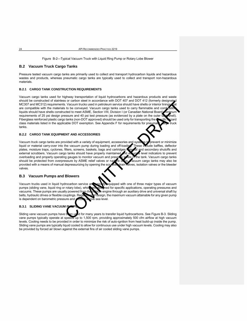
Figure B-2—Typical Vacuum Truck with Liquid Ring Pump or Rotary Lobe Blower
B.2 Vacuum Truck Cargo Tanks
Pressure tested vacuum cargo tanks are primarily used to collect and transport hydrocarbon liquids and hazardous wastes and products, whereas pneumatic cargo tanks are typically used to collect and transport non-hazardous materials.
B.2.1 CARGO TANK CONSTRUCTION REQUIREMENTS
Vacuum cargo tanks used for highway transportation of liquid hydrocarbons and hazardous products and waste should be constructed of stainless or carbon steel in accordance with DOT 407 and DOT 412 (formerly designated MC307 and MC312) requirements. Vacuum trucks used in petroleum service should have shells or interior linings that are compatible with the materials to be conveyed. Vacuum cargo tanks used to carry flammable and combustible liquids should have shells constructed to meet ASME, Section VIII, Division I (or Canadian National Board) minimum requirements of 25 psi design pressure and 40 psi test pressure (as evidenced by a plate on the outer tank shell). Fiberglass reinforced plastic cargo tanks (non-DOT approved) should be used only for transporting the specific hazard class materials listed in the applicable DOT exemption. See Appendix F for requirements for pneumatic cargo truck tanks.
B.2.2 CARGO TANK EQUIPMENT AND ACCESSORIES
Vacuum truck cargo tanks are provided with a variety of equipment, accessories and systems to prevent or minimize liquid or material carry-over into the vacuum pump during loading and off-loading. These include baffles, deflector plates, moisture traps, cyclones, filters, screens, baskets, bags and cartridges, internal and secondary shutoffs and external scrubbers. Vacuum cargo tanks should have properly maintained and accurate level indicators to prevent overloading and properly operating gauges to monitor vacuum and pressure levels in the tank. Vacuum cargo tanks should be protected from overpressure by ASME relief valves or rupture discs. Vacuum cargo tanks may also be provided with a means of manual depressurizing by opening the scrubber drain valves, isolation valves or the bleeder valves.
B.3 Vacuum Pumps and Blowers
Vacuum trucks used in liquid hydrocarbon service are typically equipped with one of three major types of vacuum pumps (sliding vane, liquid ring or rotary lobe), which are designed for specific applications, operating pressures and vacuums. These pumps are usually powered from the vehicle engine through an auxiliary drive and universal shaft by belts, hydraulic drives or flexible couplings. Regardless of design, the maximum vacuum attainable for any given pump is dependent on barometric pressure and altitude above sea level.
B.3.1 SLIDING VANE VACUUM PUMPS
Sliding vane vacuum pumps have been used for many years to transfer liquid hydrocarbons. See Figure B-3. Sliding vane pumps typically operate at speeds up to 1,500 rpm, providing approximately 500 cfm airflow at high vacuum levels. Cooling needs to be provided in order to minimize the risk of auto-ignition from heat build-up inside the pump. Sliding vane pumps are typically liquid cooled to allow for continuous use under high vacuum levels. Cooling may also be provided by forced air blown against the external fins of air cooled sliding vane pumps.
COMMITTEE DRAFT

Sliding vaturns withDuring rovolume dtained in housing bprior to di
B.3.2 LI
Liquid rin700 rpm, multi-bladwater). Thoutward apeller, creagainst thHowever,operatingrisk of aut
ane pumps uhin the pumpotation, the adecreases othe cylinder
by centrifugascharge.
IQUID RING
g pumps arproviding a
de impeller mhe pump caagainst the eating both she service liq, excess hyd
g temperaturto-ignition.
usually havep housing, thair space voln the other r to lubricateal force. The
G VACUUM
re used to trpproximatel
mounted eccasing has bopump casinsuction and quid or gel adrocarbon vres, heat ma
SAFE OPERAT
Figure B-3
e fiber vaneshe vanes arelume on oneside, respe
e the vanes e use of lubr
PUMPS
ransfer liquidy 5,000 cfm
centrically inoth a suctiong by centrifudischarge. A
and dischargvapor may bay build up d
TION OF VACUU
3—Typical S
s which are ae held in pose side of the
ectively creaand minimi
ricating oil re
ds or solid mm airflow at hnside a casinn and a discugal force. AAs the pumged throughbe exhausteuring the co
UM TRUCKS IN P
Sliding (Rota
attached to asitive contace cylinder incating pressurze wear as
esults in oil s
materials. Liqhigh vacuumng (see Figuharge port. AAir and servp rotates, th
h a dischargeed into the aompression c
PETROLEUM SE
ary) Vane P
an eccentricact with the sidcreases durre and vacuthe vanes a
saturated ai
quid ring pum levels. Liqure B-4) partAs the pum
vice liquid mhe air and vae port. The satmosphere.cycle and m
RVICE
Pump
ally mounteddes of the cyring one halfuum. A consare pushed r that needs
umps typicaluid ring vacially filled wip impeller ro
move continuapor enterinservice liqui. Although liust be dissip
d, slotted rotylinder by cef of the revostant supplyoutward ag
s to be sepa
lly operate auum pumpsth a service otates, the l
uously in andg the pump d serves to iquid ring pupated so as
tor. As the roentrifugal for
olution while y of oil is maainst the purated or filte
at speeds ups have a sing
liquid (typiciquid is pushd out of the is compressseal the pumumps have to minimize
25
otor rce. the
ain-ump ered
p to gle,
cally hed im-sed mp. low the
COMMITTEE DRAFT

26
F
Figu
igure B-5—
ure B-4—L
—Rotary Lob
API RECOMME
iquid Ring P
be Blower (2
ENDED PRACTIC
Pump – Mov
2-Lobe Impe
CE 2219
ve figure to
ller) Move
section.
figure to section.
COMMITTEE DRAFT

.
The servipump. Duexpelled tservice liqand absohazardou
B.3.3 R
Rotary lobused on pmaterialsRotary lovacuum poperated hydrocarbmanufactvacuum/p
Rotary lobshafts, roincoming the blowesame evechanicallybe discha
Rotary locause extor filters uardous m
F
ce liquid in luring operatto the reservquid make-uorbed produus materials
ROTARY LO
be blowers apneumatic c. Rotary lobbe blowers pressure ratat 1,800 rpm
bons, creatiturers have pressure rat
be blowers tating in oppair is trappe
er casing to en though thy with no serarged direct
be blowers treme dischused on rota
materials mus
igure B-6—
iquid ring puion, hydrocavoir, reducinup as the sect. Additionamust be pro
OBE BLOWE
are typically conveyors abe blowers o
may have ttios in ordem, as speedng a potentdeveloped sios for use i
typically havposite directed between the outlet ahere may brvice liquid. to the atmo
are usually arge tempeary lobe blost be proper
SAFE OPERAT
—Rotary Lob
umps circulaarbon vaporng the amouparator is coally, serviceoperly dispo
ERS
used to tranare designedoperate up tto be operatr to safely tds increase tially hazardsmall rotary n transferrin
ve two (or thtions inside athe lobe andnd discharge temperatuTherefore, dsphere.
limited to aratures, resuwer operatiorly disposed
TION OF VACUU
be Blower (3
ates in a closr present in tunt of vapor onstantly dise liquid that sed of in ac
nsfer solid md to operateto 3,600 rpmted at lowertransfer hydover 3,600
dous conditilobe blowe
ng hydrocarb
hree) figure a casing. Sed the casinged. With coure or baromduring opera
approximateulting in distons that bec of in accord
UM TRUCKS IN P
3-Lobe Impe
sed loop throthe inlet air concentratio
scharging aibecomes c
ccordance w
materials, bute at high vacm and providr speeds, redrocarbon liqrpm, the reson both insrs producingbon liquids).
eight shapeee Figures Bg, producing nstant speemetric pressation, any hy
ely 16 in. Hgtortion of thecome contadance with a
PETROLEUM SE
ller) Move
ough a resestream is abon in the disir that may c
contaminatedwith appropria
t may also bcuum/pressude up to 7,0educed airfloquids. Althosultant high side the blowg high vacuu
ed gear-driveB-5 and B-6.
a vacuum. ed operationsure variancydrocarbon v
g vacuum bee impeller anminated by appropriate
RVICE
figure to s
ervoir to mainbsorbed throscharge air. contain smad by absorbate regulato
be used for liure ratios in000 cfm airflow rates (beough rotary vacuum/prewer and at um at low a
en lobe imp. As each loThe trapped, the displac
ces. Rotary vapors pres
ecause opend casing. Aabsorbed hregulatory re
ection.
ntain the proough the seSome syste
all amounts obed hydrocaory requirem
iquids. Rota order to halow at high velow 1,000 clobe blower
essure ratio the exhaust
air capacity r
ellers, mounbe passes td air is then ced volume lobe blowerent in the inc
eration at higAdditionally, hydrocarbonequirements
oper level in rvice liquid aems provideof service liqarbons or ot
ments.
ry lobe blowandle bulk svacuum levcfm) and lowrs are normatomizes liqt. (Note: Sorates and low
nted on parahe blower inmoved throuis basically rs operate mcoming air m
gher levels ccollection ba
ns or other hs.
27
the and
e for quid ther
wers olid
vels. wer
mally quid ome wer
allel nlet, ugh the
me-may
can ags
haz-
COMMITTEE DRAFT

28 API RECOMMENDED PRACTICE 2219
B.4 Vacuum Truck Ignition Control
Diesel powered vacuum truck engines and auxiliary diesel powered vacuum units are preferred for use in flammable and combustible liquid service. This is because the limited electrical systems of diesel engines provide for reduced ignition and fire hazards as compared with those of gasoline engines. Diesel engines, however, are not totally free from ignition sources. Electrical devices and external wiring, especially on the truck chassis near the vacuum cargo tank, must be maintained in good condition to prevent breaks which may cause electrical arcing.
B.4.1 Diesel engine “runaway” or “dieseling” will occur if high concentrations of flammable vapors enter the diesel engine air intake. Several companies manufacture manual or automatic emergency shutdown devices that close the air intake to protect engines from dieseling. Their effectiveness is only as good as the initial design, installation and maintenance. If engine power is not needed for vacuum truck operation the engine should be shut down. If engine power is needed, dieseling and runaway can best be avoided by locating the vehicle upwind of vapor sources and by extending the vacuum pump discharge away from the engine air intake. In some work areas, shutdown devices are required by 30 CFR 250.80 and 250.100.
B.4.2 When installed, spark-arresting exhaust systems should be inspected frequently to ensure proper operation. USDA Forest Service Spark Arrestor Guide General Purpose and Locomotive, Volume 1 provides guidance. Shielded ignition systems, flame arrestors and spark-arresting exhaust systems are not foolproof and should not be considered as substitutes for maintaining vapor-free work areas.
B.5 Vapor Control and Recovery Equipment
Exhausted vapors may be directed from the vacuum discharge to portable or facility vapor recovery units. In these cases, flame arrestors shall be located in the vapor recovery line, near the vapor recovery unit, to prevent flashback into the vacuum truck.
Alternately, carbon adsorber canisters may be connected to the vacuum discharge exhaust. If used, these canisters must be properly rated in order to handle the amount of airflow generated by the vacuum pump. The canisters should be bonded to the vacuum units to prevent static charge buildup. The canisters should be inspected and replaced before they become saturated by lubricating oil or contaminated by exhaust vapors, as spontaneous combustion could occur.
An analysis should be conducted to determine the proper safety measures required prior to each specific use of vapor control canisters and vapor recovery systems.
B.6 Vacuum Transfer Hoses, Tubes, Suction Nozzles and Connectors
Vacuum transfer hoses, tubes and suction nozzles are designed to transfer specific liquids and dry materials. Some are designed to transfer only solid materials such as gravel, sand and powders while others are designed for septic and sewerage operations. When transferring flammable and combustible liquids or other hazardous products, espe-cially when there is potential for a flammable atmosphere in the area, it is important to select appropriate hoses, tubes, suction nozzles and connectors. Although vacuum transfer hoses and suction tubes are available in diameters of from 2 to 8 in., 3 and 4 in. diameter hoses are most commonly used in petroleum facilities.
B.6.1 Vacuum truck operators may use either conductive or nonconductive hose. It is sometimes difficult to distin-guish between the two. Conductive hoses are constructed of conductive material or have thick walls with imbedded conductive wiring. Conductive hoses should provide a suitable electrical conductance less than or equal to one megohm (1 x 10⁶ W) per 100 ft (determined by the hose manufacturer). Conductive hoses should provide a suitable electrical conductance less than or equal to one megohm (1 x 10⁶ Ω ) per 100 ft (determined by the hose manufac-turer).Thin walled, metallic spiral wound, conductive hoses are also available. However, use of these types of hoses is discouraged since they could discharge static electricity through the thin plastic which covers the metal spiral.
COMMITTEE DRAFT

SAFE OPERATION OF VACUUM TRUCKS IN PETROLEUM SERVICE 29
B.6.2 When using conductive hose, operators should assure that suction nozzles, tubes, metal hose flanges, cou-plings, fittings and nozzles are constructed of conductive materials and are securely connected so as to provide a continuous bond through the system from the vacuum truck to the source or receiving container.
B.6.3 Use of non-conductive hose to handle flammable and combustible materials should generally not be allowed due to potentials for accumulation and discharges of static electricity that can act as sources of ignition. Even where there appears to be minimal potential for the creation of a flammable atmosphere, prudent use of non-conductive hose requires that all exposed connectors, such as suction nozzles, tubes, metal hose flanges, couplings and fittings are constructed of conductive materials and each one is individually bonded and grounded to the vacuum truck and the source or receiving container.
B.7 Vacuum Truck Regulatory Requirements
The design, construction, inspection, maintenance and operation of vacuum trucks must comply with applicable fed-eral, state and local regulations.
B.7.1 Vacuum cargo tanks that carry hazardous dry materials or flammable and combustible liquids on U.S. high-ways outside of petroleum facilities must meet the construction requirements of 49 CFR Parts 178.345 – 178.348, DOT 407 or DOT 412 (formerly DOT 307 and 312) for transporting hazardous waste. Many tanks previously man-ufactured to DOT 307 and DOT 312 requirements are still in service. These requirements include items such as relief, isolation, emergency and safety valves; rollover protection; lighting and reflectors; rear valve protection; and required placard and document holders. A DOT hazardous material code name plate should be attached to the tank per 49 CFR 178.345-14(b) and a specification plate shall also be attached per 49 CFR 178.345-14(c).
B.7.2 Vacuum trucks which leave the facility, and operate on public highways, must be properly placarded (either full or empty), have the required shipping documents available and meet other regulatory requirements for highway travel. Empty trucks are exempt IF they previously carried a non-regulated material or have been properly flushed and cleaned of hazardous material and contain no residue of a hazardous material.
B.7.3 Other sections of 49 CFR applicable to vacuum truck construction, equipment and operation include, but are not limited to, the following:
Part 172, Hazardous Materials Tables and Hazardous Materials Communications Regulations.
Part 178, Design and Construction, Cargo Tanks.
Parts 100 – 185 Hazardous material regulation.
Parts 40 and 300 – 399 Federal Motor Carrier Safety Regulations (FMCSR).
B.8 Vacuum Truck Engines
Vacuum trucks are designed using on-road vehicles with on-road engines. On-road vehicles designed with on-road engine that conforms to US EPA emission standards for On-Road Certification for 2007 or the US EPA emission standards for On-Road Certification for 2010 will have a diesel particulate filter (DPF). A diesel particulate filter is an emission control technology that is designed to remove diesel particulate matter or soot from the exhaust gases of a diesel engine. The DPF is designed to physically capture, trap, and store exhaust particles in the filter and permit exhaust gases to flow through. Through normal operations, the collected particles will restrict the filter and the filter must be regenerated. Regeneration is the process of burning the collected particles by raising the exhaust temper-ature. The particulate matter will begin to burn at 600° F. The two types of regeneration are passive and active. The passive regeneration will take place automatically when the engine needs a cleaning. The active regeneration occurs when the vehicle is not moving and the engine is idling and is initiated by the engine control software.
COMMITTEE DRAFT

30 API RECOMMENDED PRACTICE 2219
Vacuum truck operators should be aware if the vehicle’s engine is in the regeneration process because of the higher temperatures. The vacuum truck operator should not load or unload during the period of time the engine is regen-erating.
COMMITTEE DRAFT

SAFE OPERATION OF VACUUM TRUCKS IN PETROLEUM SERVICE 31
APPENDIX C—VACUUM TRUCK PREVENTIVE MAINTENANCE - INFORMATIVE
C.1 General
As with any equipment used in critical service, vacuum truck tractors, engines, electrical systems, vacuum pumps, cargo tanks, valves, filters, separators, auxiliary pumps, hoses, nozzles, connectors, bonding and grounding cables and other appurtenances must receive appropriate preventive maintenance and comply with applicable regulations. The use of “should” in this section is meant as a reminder of requirements. Vacuum trucks should be inspected, tested and maintained by vacuum truck owners in accordance with applicable regulations such as federal and state DOT, local government, etc. (whichever are more restrictive). Typical preventive maintenance items for vacuum trucks include, but are not limited to, the following:
C.2 Air Tanks
Vacuum truck air tanks should be checked regularly, depending on service and atmospheric conditions, for accu-mulated water or liquid. Air tanks may require daily draining of water during cold weather, especially if an air dryer is not installed or is not working properly.
C.3 Lights and Electrical
Proper lighting is necessary, not only for driving after dark or under other low-visibility conditions but also for safe loading and off-loading. Lights and reflectors should be kept clean and inoperative lighting replaced as soon as pos-sible. The condition of the electrical system should be inspected regularly to prevent ignition sources. Inoperative or defective wiring should be repaired or replaced prior to conducting transfer operations.
C.4 Vacuum Pumps and Appurtenances
The manufacturers' recommendations should be followed regarding installation, operation, pressure limitations, testing and maintenance of vacuum pumps. Correct lubrication of the pump, bearings and associated equipment is very important. The three major causes of vacuum pump failure are (1) lack of or improper lubrication, (2) overheating and (3) foreign materials contaminating the pump.
Pumps should be checked for leaks, proper valve seating, housing cylinder wear and vane, lobe impeller or rotor wear. Repairs or replacements should be made as necessary. If pumps are belt driven, belts should be inspected regularly for wear depending on their condition, use and service and adjusted to reduce friction and heat buildup resulting from slippage. Cast iron rings in liquid ring pumps used for transferring hydrocarbon liquids, spent acids, etc. should be checked for corrosion. Traps, scrubbers, mufflers, filters and separators should be regularly inspected and maintained to assure proper operation and prevent contamination of the pump. Hoses should be inspected for cracks, leaks and worn casings and tested for conductivity. Nozzles, fittings and connections should be checked to assure that there is no blockage and they will allow tight, conductive connections.
C.5 Vacuum Truck Cargo-Tank
Vacuum truck cargo tanks, gauges, pressure and vacuum relief valves and appurtenances should be regularly in-spected, tested and maintained by vacuum truck owners depending on their condition and service. Proper mainte-nance of door gaskets, float shutoffs and level indicators is also important. Maintenance should be performed in ac-cordance with appropriate regulations, such as DOT HM 183.
Good practice dictates the need for maintenance while other inspection and maintenance requirements are manda-tory and should be performed in accordance with appropriate regulations. Regulations such as DOT HM 183 establish many different testing, inspection and maintenance requirements for tank trucks, including vacuum trucks and vacuum cargo tanks. These are too numerous to be covered in this document. Additional information is provided by the Na-tional Tank Carriers Inc. in their Cargo Tank Maintenance Manual.
COMMITTEE DRAFT

32 API RECOMMENDED PRACTICE 2219
APPENDIX D—SAFE VACUUM TRUCK OPERATIONS (INFORMATIVE)
D.1 Pre-Operation Inspection
Vacuum truck owners and vacuum truck operators should check the following items, as a minimum, before vacuum trucks are operated:
D.1.1 Prior to selecting a vacuum truck for a specific job, vacuum truck owners should assure that:
a. Pressure valves, relief valves and shutoff valves are properly sized for the pump, tank and work performed; are correctly installed; and have been inspected to be in proper operating condition.
b. Electrical continuity checks of the truck's grounding and bonding cables and conductive hoses have been per-formed on a regularly scheduled basis depending on their condition and service.
c. Where provided, intake filters, vapor recovery canisters, flame arrestors, secondary moisture traps, screens, muf-flers, exhaust filters, etc. are properly sized, installed and in good condition.
D.1.2 Prior to using a vacuum truck, vacuum truck operators should check that:
a. All valves operate freely, are leak tight and, where appropriate, can be capped while in transit.
b. Floats for liquid level indicators, internal shutoffs and scrubber shutoffs move freely and are working properly.
c. Rubber seats on interior shutoffs and exterior scrubber shutoffs are in good condition and seat properly. All con-nections and other equipment are leak free and in good working order.
d. Rear door and dome gaskets are in good condition and seal tightly when the domes are closed. This may be checked by applying pressure to the cargo tank.
e. Hoses, connections and fittings are in good condition, diameters are not smaller than the pump intake and their conductance and materials of construction are appropriate for the application.
f. Bonding and grounding cables are checked for continuity,
g. Any debris or loose components that may be present in the interior of the vacuum truck cargo tank have been removed.
H The cargo tank has been properly cleaned after previous off-loading to prevent reactions between incompatible products and contamination of the product to be loaded. The cargo tank should be free of moisture or water if products to be loaded react with water.
I Hoses have been drained and are appropriately capped for transit.
D.1.3 Prior to commencing vacuum truck operations, personnel associated with the operations should conduct a job hazard safety analysis (sometimes also referred to as a job safety hazard analysis) to identify potential hazard ex-posures and ensure protective equipment, procedures and contingency plans are in place to mitigate risks associated with identified hazards. The entire crew engaged in the vacuum truck operations, including third party workers, should review the most current JHA/JSA to gain familiarity with the hazards, risks and the appropriate safeguards. (See OSHA Publication 3071, Job Hazard Analysis, or other JSA-related material from OSHA's web site for more information on hazard analyses.)
COMMITTEE DRAFT

SAFE OPERATION OF VACUUM TRUCKS IN PETROLEUM SERVICE 33
D.2 Facility Loading and Off-Loading Procedures
Vacuum truck operators transfer many different petroleum products, by-products, wastes and spilled materials, often in the same facility. The facility operator should provide the vacuum truck operator with instructions that include, but are not limited to, the following items:
a. The exact location, tank or vessel in the facility where the truck is to proceed and stage to load or off-load.
Note: Fires have occurred when a vacuum truck was parked too close to the source of flammable vapors e.g. tank manholes, and vents.
b. The requirements for entry of the vacuum truck into restricted areas within the facility.
c. Whether the product is to be reprocessed or transported to a separator or waste disposal area.
d. The applicable facility permits required for the job and product transfer, on and off premises.
e. The product to be transferred and product safety information including, but not limited to, toxicity, corrosiveness, flammability, reactivity or combustibility. Where a specific product is involved, an SDS may be used to provide this information; however, when the material being transferred is a mixture of many products, a contaminated product or a waste product, an SDS may not be available and other appropriate information will be required.
f. The specific personal protective equipment required, if any.
g. Applicable facility safety and emergency response procedures, including the telephone number or other means of contacting facility personnel or appropriate emergency responders.
D.3 Vacuum Truck Cargo Tank Loading
Vacuum truck operators should remain within the mechanical operational limits of the equipment (as established by equipment manufacturers) to prevent over-pressurizing tanks or releasing product and vapor. Vacuum truck owners should assure that vacuum truck operators are trained and aware of the applicable regulatory requirements and the following minimum safe operating procedures when loading vacuum cargo tanks:
D.3.1 Obtain required facility permits and work orders for this activity, as appropriate.
D.3.2 Position the vacuum truck in a safe, authorized position, at least 25 ft. upwind or crosswind from the source container or spill. Set the brakes and chock the wheels. When removing flammable liquids from a tank, container or vessel located in a diked area, the vacuum truck should be positioned at least 50 ft. upwind from the tank, preferably on top of the dike or outside the dike.
D.3.3 Ground the vacuum truck using the static line. If the transfer is between two trucks or between the vacuum truck and a metal tank or vessel, assure that the source truck, tank or vessel is both grounded and also bonded to the receiving vacuum truck.
D.3.4 Place an appropriate portable fire extinguisher (minimum 20 lb. BC) ready for use, within close proximity of the operation.
D.3.5 Assure that metal hose couplings, nozzles, etc. are tightly connected. The suction hose should be connected directly to a pipe connection or fitting on the source container at a level below the product liquid level, or the suction nozzle should be fully submerged into the product.
D.3.6 Use approved conductive hose, couplings, connectors and nozzles that are in good condition, for the product transfer. The conductivity from the vacuum truck to the source container may be checked with an ohmmeter. Check the conductivity from the vacuum truck to the source container with an ohmmeter or other approved testing device.If
COMMITTEE DRAFT

34 API RECOMMENDED PRACTICE 2219
thin-walled conductive hose or non-conductive hose is permitted to be used by the facility, assure all conductive couplings, connections and nozzles are properly and individually bonded to the source container and grounded. See Section 3. See Section 5.3 and 5.4 for additional information.
D.3.7 Determine the amount of product to be transferred and assure the vacuum truck cargo tank has sufficient capacity. Bond gauging equipment to the source container prior to insertion.
D.3.8 If the amount of product to be transferred is greater than the capacity available in the vacuum truck cargo tank, calculate the flow rate (gallons per minute) and estimate the time when the cargo tank will be approximately 90% filled. Monitor tank gauges and the transfer time in order to stop transfer operations when the cargo tank is full and before a spill or release occurs.
D.3.9 Using a vacuum flow chart for the pump in use, determine the amount of vacuum and flow rate required to transfer the liquid. Calculating the ability of the vacuum pump to make the transfer at the proposed lift is important for safe operation. If the ability to pull sufficient vacuum operators may be tempted to bounce the hose end in and out of the liquid in an attempt to establish suction. This condition permits large amounts of air entrainment creating a potentially hazardous condition. See Table D-1, Example Vacuum / Flow Rate Table, and Table D-2, Hose Flow Rate Adjustment Chart, for an example of how to use charts to determine vacuum/pressure flow rates for different lifts, vacuums and various hose diameters and lengths.
Table D-1—Example Vacuum / Flow Rate Table
Approx. Flow (gpm) per 100 ft. Straight Hose
Approximate Lift (ft)
Vacuum (in. hg)
Pressure (psi)
3 in. hose diameter
4 in. hose diameter
6 in. hose diameter
4.5 4 2.00 135 287 835
9.0 8 4.00 196 418 1,214
13.6 12 6.00 244 520 1,511
18.1 16 8.00 285 608 1,765
22.7 20 10.00 322 685 1,991
27.2 24 12.00 355 756 2,197
31.7 28 14.00 386 822 2,388
How to Calculate Flow Rates in Gallons per Minute (gpm) Using the Vacuum/Flow Rate Table
1. In Table D-1, determine the hydraulic lift in ft and the matching inches of Hg vacuum for this lift
2. Determine the maximum, continuous operation, inches of Hg vacuum for the pump in use.
3. Subtract the inches of Hg determined in (1), from the maximum inches of Hg in (2).
4. Using Table D-1, find the appropriate gpm flow rate for 100 ft of “x” diameter hose, based on the calculated inches of Hg in (3).
D.3.10 After developing the flow rate for a 100-foot long hose, calculate the adjustment needed in order to determine the flow rate to be obtained for the specific diameter and length of hose to be used for the specific transfer.
COMMITTEE DRAFT

SAFE OPERATION OF VACUUM TRUCKS IN PETROLEUM SERVICE 35
Table D-2—Hose Flow Rate Adjustment Chart
Hose Length (ft) % of Flow-100 ft Hose
20 220.0 %
25 211.4 %
50 145.4 %
75 116.8 %
100 100.0 %
150 80.3 %
200 68.8 %
Example: Determine the flow rate for 50 ft long, 4 in. diameter hose, with a lift (head) of 18 ft using a vacuum pump rated at 24 in. Hg.
Step 1. Lift (18 ft) = (16 in. Hg) (Table D-1)
Step 2. Vacuum pump rating (24 in. Hg) – (16 in. Hg) = 8 in. Hg (Table D-1)
Step 3. 8 in. Hg provides flow of 418 gpm in a straight 4 in. diameter hose (Table C-1).
Step 4. The flow rate (Table D-2) in a 50 ft long hose is 145.4% of that In a 100 ft long hose. 145.4% x 445 = 647 gpm (flow rate in 50 ft, 4 in. diameter hose)
D.3.11 Open the top isolation valves and close all other valves, and set the pump to operate in the vacuum mode.
D.3.12 If the hose is not already directly connected to the source vessel at a level below the product level, submerge the suction nozzle hose into the product. Minimize entrained air with liquids entering the vacuum truck cargo tank, by keeping the suction hose submerged or connected during the entire operation.
D.3.13 Start the power source, engage the vacuum pump, and allow the vacuum inside the cargo tank to build up to maximum level. As soon as sufficient vacuum is built up in the cargo tank, shut off the vacuum system, open the inlet valve and begin loading. If sufficient vacuum cannot be sustained, continue operating the vacuum pump until the loading is completed.
D.3.14 When the hose is partially submerged (when product levels reach the bottom of the source container or when product is being skimmed off of the surface), minimize the amount of air introduced into the system by adjusting the vacuum pump air flow rating in proportion to the hose diameter.
See Table D-3 for suggested airflow rates when the air enters the system.
Table D-3—Suggested Vacuum Pump Airflow Rate/Hose Diameter Adjustment Required When the Suction Hose isPartially Submerged (Skimming) to Minimize the Amount of Air Entering the Vacuum System.
AIR FLOW 300 cfm VP 500 cfm VP 700 cfm VP 1,000 cfm VP
COMMITTEE DRAFT

36 API RECOMMENDED PRACTICE 2219
2 in. diameter hose X
3 in. diameter hose X
4 in. diameter hose X
6 in. diameter hose X
D.3.15 There is an increased risk of sucking air and hydrocarbon in an attempt to establish flow if vacuming from the top of a tank that has marginal lift.
D.3.15 Use a suction screen or filter, where required, to prevent undesired materials such as rocks and debris from entering the vacuum truck tank. Assure that the screen is bonded to the tank and/or to the conductive hose coupling and nozzle to prevent a static spark hazard.
D.3.16 Where vapor recovery is mandated, exhausted vapors may be directed back to the source tank (or vessel). In such cases, locate a suitable flame arrestor in the vapor recovery line, close to and between the source container and the vacuum exhaust to prevent flashback into the vacuum truck tank. For information on flame arrestors in piping refer to API RP 2028.
D.3.17 Alternately, exhausted vapors may be directed to a portable or facility vapor recovery unit. In such cases, locate a suitable flame arrestor in the vapor recovery line between the vacuum discharge exhaust and the vapor re-covery unit, in an appropriate position close to the vapor recovery unit, to prevent flashback into the vacuum truck tank. The potential exists for carbon adsorber vapor recovery units to become saturated by vacuum pump lubricating oil or contaminated by exhaust vapors, resulting in spontaneous combustion. For information on flame arrestors in piping refer to API RP 2028.
D.3.18 In some cases, the vacuum discharge exhaust may be fitted with a carbon adsorption canister. If such can-isters are used, they must be properly rated for the air flow capacity of the vacuum pump and positively bonded to the vacuum unit to prevent buildup of static charges. The potential exists for carbon adsorber canisters connected to the vacuum discharge exhaust to become saturated by vacuum pump lubricating oil or contaminated by exhaust vapors, resulting in spontaneous combustion. Therefore, an approved flame arrester is required on the inlet to the carbon canister to prevent flames from traveling to the vacuum truck. For information on flame arrestors in piping refer to API RP 2028.
D.3.19 Where vapor recovery is not required and vapors are vented to the atmosphere, direct the released vapors away from ignition sources such as the vacuum truck's engine and motor vehicle paths of travel and away from areas where people are present.
D.3.20 The potential travel path of vapors discharged during off-loading, atmospheric and wind conditions, topog-raphy of the surrounding area including low spots where vapors may collect and potential ignition sources must be considered prior to starting operations. Vent only to a hazard-free area (depending on atmospheric conditions) by either of the following methods:
a. Attach a length of exhaust hose sufficient to reach an area that is away from the source of the liquids, at least 50 ft downwind of the truck and free from sources of ignition, personnel exposure or other hazards.
b. Use a safety venturi and vertical exhaust stack to discharge vapors at a diluted rate, at the top of the re-ceiving container, at least 12 ft above the ground level, directed downwind and away from sources of ignition and other hazards, during the loading operation.
COMMITTEE DRAFT

SAFE OPERATION OF VACUUM TRUCKS IN PETROLEUM SERVICE 37
D.3.21 When transferring flammable liquids or hazardous materials, stay within 25 ft. of the truck (between the vacuum truck and the source tank, vessel or container) throughout the operation. If this is not possible due to the job site conditions or design of the vacuum truck then an observer shall be so positioned and be in verbal communication with the vacuum truck operator. This is required in order to quickly close the product valve and stop the pump in the event of a blocked line, release of material through a broken hose or connection or other emergency.
D.3.22 Exercise caution as vapors may reach the flammable range during low flow periods such as the final few minutes of loading or under other conditions.
D.3.23 Load the tank until the liquid level indicator shows full or the internal shutoff device engages. When the tank is full, close the inlet valve.
D.3.24 Disengage the vacuum pump and bleed off the vacuum by opening the bleeder valve, equalizing the tank pressure. Close the isolation valve and disengage the power source.
D.3.25 Disconnect the suction hose and drain any liquid back into a proper container. Close and cap the bleeder valve. Open the outside scrubber (liquid-entry preventer) drain valves. Catch any liquid for proper disposal. Immedi-ately report any spills or releases to facility management.
D.3.26 Disconnect the bonding cable and then disconnect the grounding static line. Wait at least one minute to allow for static dissipation before disconnecting the bonding cable and then disconnect the grounding static line.
D.3.27 Remove the wheel chocks and assure that the vacuum truck is properly placarded and that the shipping papers are in order for materials carried, before leaving the facility.
D.4 Cargo-Tank Off-Loading
D.4.1 GENERAL OFF-LOADING PROCEDURES
Vacuum trucks may be off-loaded by gravity, pressurizing with air or inert gas, or by using pressure from reversing the vacuum pump or from an external pump. Vacuum truck operators should remain within the mechanical operational limits of the equipment (as established by equipment manufacturers) to prevent over-pressurizing tanks or releasing product and vapor. See also attendant requirements specified in 5.12.4. Vacuum truck owners should assure that vacuum truck operators are trained and aware of the applicable regulatory requirements and the following minimum safe operating procedures when off-loading vacuum cargo tanks:
D.4.1.1 Review the fire and health hazards of the material to be off-loaded and the off-loading method and facilities to be used. Obtain appropriate permits and work orders for this activity, as required by the facility. Avoid open dumping of potentially flammable or toxic materials without a specific hazard review and control of ignition sources and exposures.
D.4.1.2 Where vapor recovery is mandated, exhausted vapors may be directed to a portable or facility vapor re-covery unit. In such cases, locate a suitable flame arrestor in the vapor recovery line between the vacuum discharge exhaust and the vapor recovery unit, in an appropriate position close to the vapor recovery unit, to prevent flashback into the vacuum truck tank. The potential exists for carbon adsorber vapor recovery units to become saturated by vacuum pump lubricating oil or contaminated by exhaust vapors, resulting in spontaneous combustion.
D.4.1.3 Where vapor recovery is not required and vapors are vented to the atmosphere, direct the released vapors away from ignition sources such as the vacuum truck's engine and motor vehicle paths of travel and away from areas where people are present.
D.4.1.4 The potential travel path of vapors discharged during off-loading, atmospheric and wind conditions, topog-raphy of the surrounding area including low spots where vapors may collect and potential ignition sources must be
Formatted: Indent: Left: 0"
COMMITTEE DRAFT

38 API RECOMMENDED PRACTICE 2219
considered prior to starting operations. Vent only to a hazard-free area (depending on atmospheric conditions) by either of the following methods:
a. Attach a length of exhaust hose sufficient to reach an area that is away from the source of the liquids, at least 50 ft downwind of the truck and free from sources of ignition, personnel exposure or other hazards.
b. Use a safety venturi and vertical exhaust stack to discharge vapors at a diluted rate, at the top of the receiving container, at least 12 ft above the ground level, directed downwind and away from sources of ignition and other haz-ards, during the loading operation.
D.4.1.2
D.4.1.3 Where vapor recovery is not required and vapors are vented to the atmosphere, direct the released vapors away from ignition sources such as the vacuum truck's engine and paths of motor vehicle travel, and away from areas where people are present. The potential travel path of vapors discharged during off-loading, atmospheric and wind conditions, topography of the surrounding area including low spots where vapors may collect and potential ignition sources all must be considered prior to starting operations. Vent only to a hazard-free area (depending on atmospheric conditions) by either of the following methods:
a. Attach a length of exhaust hose sufficient to reach an area that is away from the source of the liquids, at least 50 ft downwind of the truck and free from sources of ignition, personnel exposure or other hazards.
b. Use a safety venturi and vertical exhaust stack to discharge vapors at a diluted rate, at the top of the receiving container, at least 12 ft above the ground level, directed downwind and away from sources of ignition and other haz-ards, during the loading operation.
D.4.1.4 Position the vacuum truck in a safe, authorized position, upwind or crosswind from the receiving container. When transferring flammable liquids into a container located within a diked area, place the vacuum truck at least 50 ft upwind from the tank, preferably on top of or outside of the dike.
D.4.1.5 Set the vacuum truck brakes and chock the wheels
D.4.1.6 Ground the vacuum truck using the static line. If the transfer is between two trucks or between the vacuum truck and a metal tank or vessel, ensure that the source vacuum truck is both grounded and also bonded to the re-ceiving truck, tank or vessel. 5.4 provides further information.
D.4.1.7 Place an appropriate portable fire extinguisher (minimum 20 lb. BC), ready for use, within close proximity of the operation.
D.4.1.8 Assure Ensure that metal hose couplings, nozzles, etc. are tightly connected. The transfer hose should be connected directly to a pipe connection or fitting on the receiving container at a level below the product liquid level, or the end of the hose should be fully submerged into the product liquid.
D.4.1.9 Use approved conductive hose, couplings, connectors and nozzles that are in good condition, for the product transfer. Check the conductivity from the vacuum truck to the receiving container with an ohmmeter. Check the conductivity from the vacuum truck to the receiving container with an ohmmeter or other approved testing device. If thin-walled conductive hose or non-conductive hose is permitted by the facility to be used, assure that all conductive couplings, connections and nozzles are properly and individually bonded to the source container and grounded, if necessary. 5.3 provides further information See Section 5.3 and 5.4 for additional information..
D.4.1.10 Determine the amount of product to be transferred and assure the receiving container tank has sufficient capacity. Bond gauging equipment to the receiving container prior to insertion.
D.4.1.11 If the amount of product to be transferred is greater than the capacity available in the receiving container, calculate the flow rate and estimate the time when the container will be approximately 90% full. Monitor tank gauges
Formatted: No bullets or numbering
COMMITTEE DRAFT

SAFE OPERATION OF VACUUM TRUCKS IN PETROLEUM SERVICE 39
and the transfer time in order to stop transfer operations before the receiving container is full in order to avoid a spill or release.
D.4.1.12 When off-loading flammable liquids or hazardous materials, stay within 25 ft of the truck (between the vacuum truck and the receiving container) throughout the operation. This is required in order to quickly stop product flow in the event of a blocked line, release of material through a broken hose or connection, overflow or other emer-gency.
D.4.1.13 Exercise caution as vapors may reach the flammable range during low flow and vapor producing periods such as the first few minutes of off-loading or under other conditions.
D.4.1.14 Load the receiving container until all product is transferred out of the vacuum truck cargo tank or the con-tainer reaches full capacity (the receiving container liquid level indicator shows full or the high- level alarm signal activates). Do not overfill the receiving container.
D.4.1.15 When the receiving container is full and the transfer is completed, close the inlet valve, disengage vacuum pump and disengage power source. Disconnect the transfer hose and drain any liquid into a proper container. Im-mediately report any releases or spills to facility management.
D.4.1.16 Disconnect the bonding cable and then disconnect the grounding static line.
D.4.1.17 Remove the wheel chocks and vent the vacuum truck tank to a safe location. Assure that the vacuum truck is properly placarded as empty and that the shipping papers are in order before leaving the facility.
D.4.2 GRAVITY OFF-LOADING
The following gravity off-loading procedures are in addition to the general off-loading procedures in Appendix D.4.1:
D.4.2.1 Open the bleeder/isolation valve to vent the vacuum truck. Vent vapors into the atmosphere to a safe loca-tion or return vapors to the receiving container.
D.4.2.2 Open the discharge valve and empty the vacuum truck cargo tank by gravity. Close the discharge valve when off-loading is complete.
D.4.3 REVERSE VACUUM PRESSURE OFF-LOADING
The following reverse vacuum pressure off-loading procedures are in addition to the general off-loading procedures in Appendix D.4.1:
D.4.3.1 Use a vacuum flow chart for the pump in use to determine the amount of pressure and flow rate required for the transfer. See Table D-1, Example Vacuum Flow Rate Table, and Table D-2, Hose Flow Rate Adjustment Chart, for an example of how to use charts to determine vacuum/pressure flow rates for different lifts, vacuums and various hose diameters and lengths.
D.4.3.2 Close all bleed and drain valves.
D.4.3.3 Start the power source and engage vacuum pump operating in pressure (reverse) mode.
D.4.3.4 Pressure the vacuum truck cargo tank. Do not exceed the pressure relief valve setting or the maximum allowable working pressure as indicated by the tank data plate, whichever is lower.
D.4.3.5 Open the truck discharge valve to off-load. Start discharge at a slow speed until the end of the discharge hose is submerged to minimize spraying or splashing of product or materials.
D.4.3.6 Stay clear of the discharge line hook-up as liquid products, rocks and debris may be discharged under considerable pressure.
COMMITTEE DRAFT

40 API RECOMMENDED PRACTICE 2219
D.4.3.7 When pressure off-loading, decrease the pump-off rate near the end of the transfer to avoid over pressuring the receiving container.
D.4.3.8 Close the discharge valve when off-loading is complete. Disengage the vacuum pump and bleed off the pressure by opening the bleeder valve, equalizing the tank pressure. Close the isolation valve and disengage the power source.
D.4.3.9 Following completion of pressure off-loading, any internal built-up pressure within the vacuum truck cargo tank must be relieved by safely venting to the atmosphere, receiving tank or vapor recovery unit.
D.4.4 AIR AND INERT GAS PRESSURE OFF-LOADING
The following air and inert gas pressure off-loading procedures are in addition to the general off-loading procedures in Appendix D.4.1:
D.4.4.1 Close all bleed and drain valves.
D.4.4.2 Connect the source of pressurized air or inert gas to the vacuum truck inlet valve.
D.4.4.3 Pressure the vacuum truck cargo tank. Do not exceed either the pressure relief valve setting or the max-imum allowable working pressure as indicated by the tank data plate, whichever is lower.
D.4.4.4 Open the truck discharge valve to off-load. Start discharge at a slow rate of speed until the end of the dis-charge hose is submerged to minimize spraying or splashing of product or materials. Stay clear of the discharge line hook-up as liquid products, rocks and debris may be discharged under considerable pressure.
D.4.4.5 When off-loading using pressurized air or inert gas, decrease the pressure near the end of the transfer to avoid over pressuring the receiving container.
D.4.4.6 Close the discharge valve when off-loading is complete. Disengage the source of air or inert gas and bleed off the pressure by opening the bleeder valve, equalizing the tank pressure. Close the isolation valve and disengage the power source.
D.4.4.7 Following completion of pressure off-loading, any internal built-up pressure within the vacuum truck cargo tank must be relieved by safely venting to the atmosphere, receiving tank or vapor recovery unit.
D.4.4.8 When venting to the atmosphere, direct the released vapors away from ignition sources such as the vacuum truck's engine and paths of motor vehicle travel, and away from areas where people are present. The potential travel path of the released vapors, atmospheric and wind conditions, topography of the surrounding area including low spots where vapors may collect and potential ignition sources all must be considered prior to starting operations.
D.4.4.9 When offloading using inert gas, the vacuum truck cargo tank should be placarded or warnings posted, such as a tag attached to the cargo tank opening, to indicate the tank contains inert gas.
D.4.5 EXTERNAL TRANSFER (AUXILIARY) PUMP OFF-LOADING
The following external (auxiliary) transfer pump off-loading procedures are in addition to the general off-loading pro-cedures in Appendix D.4.1:
D.4.5.1 Use a vacuum flow chart for the auxiliary pump to be used to determine the amount of pressure and flow rate required for the transfer. See Table D-1, Example Vacuum Flow Rate Table, and Table D-2, Hose Flow Rate Ad-justment Chart, for an example of how to use charts to determine vacuum/pressure flow rates for different lifts, vac-uums and various hose diameters and lengths).
D.4.5.2 Close all bleed and drain valves.
COMMITTEE DRAFT

SAFE OPERATION OF VACUUM TRUCKS IN PETROLEUM SERVICE 41
D.4.5.3 Start the power source and engage auxiliary pump, operating in pressure mode.
D.4.5.4 Open the truck discharge valve to off-load. Start discharge at a slow speed until the end of the discharge hose is submerged to minimize spraying or splashing of product or materials. Stay clear of the discharge line hook-up as liquid products, rocks and debris may be discharged under considerable pressure.
D.4.5.5 Decrease the pump-off rate near the end of the transfer to avoid over pressuring the receiving container.
D.4.5.6 Close the discharge valve when off-loading is complete. Disengage the auxiliary pump and equalize the tank pressure by opening the bleeder valve. Close the isolation valve and disengage the power source.
D.4.5.7 Following completion of off-loading, any internal built-up pressure within the vacuum truck cargo tank must be relieved by safely venting to the atmosphere, receiving tank or vapor recovery unit.
COMMITTEE DRAFT

42 API RECOMMENDED PRACTICE 2219
APPENDIX E—SAFE OPERATION OF VACUUM TRUCKS TO REMOVE FLAMMABLE AND COMBUSTIBLE LIQUIDS FROM UNDERGROUND TANKS AND SIMILAR SERVICES AT
SERVICE STATIONS , ETC. – INFORMATIVE
E.1 General
Vacuum trucks (or tank trucks with transfer pumps) are often used to remove flammable and combustible liquids, hazardous waste and contaminated water from underground (and other) storage tanks at service stations and commercial facilities where potential hazards may exist due to external sources and close proximity to the public. Vacuum truck and tank truck owners should assure that operators are trained and aware of the safety procedures applicable to the removal of these products from underground tanks at service stations and commercial facilities. Safe operations are especially important where access by the public and persons other than facility employees is possible.
E.2 Vapor Releases, Spills and Leaks
Because transfer of flammable and combustible liquids from underground storage tanks requires a running engine, it is essential that strict operating procedures and controls be established and maintained during all phases of the re-moval operation to prevent any release of liquid or vapors from reaching sources of ignition. See 5.6, Vacuum Exhaust Venting and Vapor Recovery, for additional information.
E.2.1 Release of vapors, spills and leaks are the primary potential hazards in the transfer of flammable and com-bustible liquids from underground tanks. Should these occur, a qualified person (truck operator, emergency responder or other individual) should use a properly calibrated and adjusted combustible gas detector to determine the extent of the area that is in the potentially flammable range. This would be any area with an atmosphere containing a vapor-air mixture, which is at or greater than 10% of the lower flammable limit. Entry into such an area by personnel without appropriate respirators or entry of vehicles should be restricted, until all flammable vapors have dissipated and the area is determined to be safe. Testing with a hydrocarbon vapor analyzer is recommended to confirm human expo-sures will be at or below PELs. In addition, operating any equipment that might be a source of ignition should also be prohibited until flammable vapors have dissipated.
E.2.2 During the transfer operations, the vacuum truck (tank truck) operator and facility personnel should continu-ously observe and monitor operations, buildings, vehicles and equipment located downwind of the transfer operation, and any other areas into which vapors may travel where a potential source of ignition could be present or occur. Even diesel engines can “run away” and become ignition sources if they aspirate significant concentrations of hydrocarbon vapors.
E.3 Vapor Recovery
The use of vapor recovery controls, such as the return of vapors through a closed system to the underground tank or the collection of vapors in a vapor recovery device, is required where mandated by regulations or company policy. An analysis should be made of the potential hazards of the specific vapor recovery method or system to be used and safety procedures established prior to the start of operations. 5.6.2, Vapor Recovery, provides additional information.
E.4 Product Removal from Underground Tanks
E.4.1 PRE-OPERATION INSPECTION AND INFORMATION
All of the items listed in Appendix D.1, Pre-Operation Inspection, are applicable to product transfer from underground storage tanks. In addition, vacuum and tank truck operators should be trained and aware of the following safe prac-tices:
a. The specific underground tank or tanks to be emptiedThe specific location and configuration of the underground tank or tanks to be emptied, the exact product to be transferred and appropriate product safety information in-cluding, but not limited to, toxicity, corrosiveness, flammability, reactivity or combustibility. Where a specific product is involved, an SDS may be used to provide this information; however, when the material being transferred is a
COMMITTEE DRAFT

SAFE OPERATION OF VACUUM TRUCKS IN PETROLEUM SERVICE 43
mixture of products, a contaminated product or a waste product, an SDS may not be available and other appro-priate information should be provided.
b. The requirements to test the atmosphere for airborne hydrocarbon vapors or toxic gas, to determine if operator exposures will be at or below PELs without respirators.
c. The applicable requirements for personal protective equipment, including respirators, if any.
d. Where the product is to be transported and whether it is considered product or hazardous waste.
e. The applicable company and regulatory permits required for the job and product transport.
f. Appropriate facility safety and emergency response procedures, including the telephone number or other means of contacting facility personnel and appropriate emergency responders
E.4.2 VACUUM TRUCK (TANK TRUCK) LOADING
To minimize risk to themselves and others Vvacuum truck (tank truck) operators should be aware of the following minimum safe work practices when transferring products from underground tanks:
E.4.2.1 Position the vacuum truck (tank truck) on level ground, at least 25 ft away from and preferably upwind of the underground tank. The appropriate location of the truck will be dependent on atmospheric conditions, wind, topog-raphy and outside activities.
Do not locate the vacuum truck near buildings, service station ingress and egress routes, pump islands, aboveground storage tanks, underground tank vent pipes, in a depressed or enclosed area or near a public roadway.
E.4.2.2 Assure that the area is free of potential hazards (such as public access) and sources of ignition including all electrical devices on the vacuum truck, heaters, open lights, smoking, fires, other running engines, motor vehicles, compressors, dispenser pumps, etc. Use rope, tape or traffic cones to designate an area approximately 25 ft in radius around the vacuum truck and the underground tank in order to prevent motor vehicles and unauthorized personnel from entering Use rope, tape or traffic cones to designate an area approximately 25 ft in radius around the vacuum truck and the underground tank to delineate an exclusion zone for motor vehicles and unauthorized personnel..
E.4.2.3 Obtain a permit for this activity if required by local regulations or company procedures. Lock and tag out tank inlet and suction lines as appropriate. Pumps and mixers should be isolated and locked out.
E.4.2.4 Set the brakes on the vacuum truck (tank truck) and place chocks under the wheels to prevent accidental movement. Bond (and ground) the truck to the fill box or fill pipe of the underground tank being emptied.
E.4.2.5 Gauge the underground tank(s) to be emptied to determine that the vacuum truck cargo tank (tank truck compartment) has sufficient capacity to hold the product to be removed, allowing a safe margin of approximate 10% outage for temperature expansion and to prevent overflow. If the amount of product exceeds the available capacity, careful monitoring is necessary in order that the product transfer is stopped prior to overfilling the vacuum tank (or tank truck compartment).
E.4.2.6 Using a vacuum flow chart (or transfer pump specifications) for the pump in use, determine the amount of vacuum and flow rate required to transfer the liquid. Table D-1, Example Vacuum Flow Rate Table and Table D-2, Hose Flow Rate Adjustment Chart, provide an example of how to use charts to determine vacuum/pressure flow rates for different lifts, vacuums and various hose diameters and lengths.
E.4.2.7 After developing the flow rate for a 100-ft long hose, calculate the adjustment needed in order to determine the flow rate to be obtained for the specific diameter and length of hose to be used for the specific transfer. See Table D-2 for Hose Flow Rate Adjustment. Calculate the approximate time required for the transfer.
COMMITTEE DRAFT

44 API RECOMMENDED PRACTICE 2219
E.4.2.8 Place an appropriate portable fire extinguisher (minimum 20 lb. BC), ready for use in the event of an emergency, within close proximity of the operation (for example, placed between the storage tank fill pipe connection and the vacuum truck or tank truck).
E.4.2.9 Use approved conductive hose, couplings, connectors and nozzles that are in good condition, for the product transfer. If thin-walled conductive hose or non-conductive hose is used, assure that all conductive couplings, con-nections and nozzles are properly and individually bonded to the source container. See Section 4 for further infor-mation. The suction hose may be equipped with a check valve to prevent any discharge of product upon disconnec-tion.
E.4.2.10 Connect the suction hose from the vacuum tank inlet valve (transfer pump) to a suction tube of sufficient length (13 ft minimum) to reach the bottom of the underground tank. Assure that all hose couplings, nozzles, etc. are tightly connected. Open the underground tank fill connection and insert the suction tube. In areas where vapor re-covery is required, use of a modified coaxial fitting is recommended.
E.4.2.11 Assure that the suction tube or hose is either directly connected to or held in constant contact with the rim of the underground tank opening or that a bonding cable is used to provide a positive connection between the tube or hose and the underground tank during product transfer. Do not connect bond clamp to underground tank openings as flammable vapors may be present.
E.4.2.12 Where vapor recovery is mandated, the vacuum truck may be fitted with a carbon adsorption canister. If used, canisters must be properly rated for the airflow capacity of the vacuum pump and positively bonded to the vacuum units to prevent static charge buildup. The potential exists for carbon adsorber canisters to become saturated by vacuum pump lubricating oil or contaminated by exhaust vapors, resulting in spontaneous combustion.
E.4.2.13 Exhausted vapors may be directed back to the underground tank. In such cases, a suitable flame arrestor should be provided in the vapor recovery line, close to and between the underground tank and the vacuum exhaust to prevent flashback into the vacuum truck cargo tank (tank truck compartment). Alternately, exhausted vapors may be directed to a portable or facility vapor recovery unit in areas where vapor recovery is mandated or desired. In such cases, a suitable flame arrestor should be located in the vapor recovery line between the vacuum discharge exhaust and the vapor recovery unit, in an appropriate position close to the vapor recovery unit, to prevent flashback into the vacuum truck cargo tank (tank truck compartment). Alternative vapor treatment options such as vapor incineration, may be permitted by the Authority Having Jurisdiction (AHJ).
E.4.2.14 Where vapor recovery is not required and vapors are vented to the atmosphere, released vapors should be directed away from ignition sources such as the truck's engine and paths of motor vehicle travel and away from areas where people are present. The potential travel paths of vapors discharged during off-loading, atmospheric and wind conditions, topography of the surrounding area including low spots where vapors may collect and potential ignition sources all must be considered prior to starting operations. Vapors should be vented only to a hazard-free area (depending on atmospheric conditions) by either of the following methods:
a. Attach a hose to the vacuum exhaust that is of sufficient length to direct the vapors away from the source of the liquids. This should be at least 50 ft downwind of the truck and other potential sources of ignition, into an area that is free from hazards and personnel exposure.
b. Use a safety venturi and vertical exhaust stack that extends at least 12 ft above the vacuum truck to discharge vapors at a diluted rate, downwind, away from sources of ignition and other hazards, during the loading operation. Non-conductive exhaust stacks are recommended where the possibility exists of contacting overhead electric power lines.
E.4.2.15 When using a vacuum truck, open top isolation valves and close all other valves. Position the pump to operate in the vacuum mode. Start the power source, engage the vacuum pump and allow the vacuum inside the tank to build up to maximum level. Operators should stay within the operational limits of the equipment as established by the equipment manufacturers to prevent over-pressurizing tanks. If the vacuum is sufficient, shut off the vacuum system, open the vacuum tank inlet valve and begin loading. Otherwise, continue operating the vacuum pump until loading is completed. When using a transfer pump, assure the pump is correctly positioned and engage the power.
COMMITTEE DRAFT

SAFE OPERATION OF VACUUM TRUCKS IN PETROLEUM SERVICE 45
E.4.2.16 Use a suction screen, where required, to prevent undesired materials such as dirt, rocks, rust and debris from entering the vacuum tank. If the vapor air mixture in the underground tank is within the flammable range, the suction screen could create a static spark hazard.
E.4.2.17 Minimize entrained air (air entrapment) with liquids from entering the vacuum truck cargo tank (tank truck compartment), by keeping the suction tube submerged into the product during the entire operation. If the tube is par-tially submerged (such as when product levels reach the bottom of the underground tank or when cleaning up a spill), control air entrainment by reducing the vacuum pump air flow rating (transfer pump speed) according to the tube and hose diameter as suggested in Table D-3, Suggested Vacuum Pump Airflow Rates.
E.4.2.18 Stay within 25 ft of the truck (between the truck and the underground tank) throughout the operation in order to quickly close the product valve and stop the pump in the event of a blocked line or release of material through a broken hose or connection.
E.4.2.19 Load the vacuum truck cargo tank (tank truck compartment) until the liquid level indicator shows 90% full or the internal shutoff device engages. When the vacuum truck cargo tank (tank truck compartment) is full, close the inlet valve.
E.4.2.20 Bleed off the vacuum by opening the bleeder valve, equalizing the vacuum tank pressure. Close the isola-tion valve and disengage the power source. If using a transfer pump, stop power.
E.4.2.21 Disconnect the suction and vapor recovery hoses and drain any remaining product in the hoses back into an approved container for proper disposal. Close and cap the bleeder valve. Open the outside scrubber (liquid-entry preventer) drain valves and catch any released liquid into an approved container for proper disposal. Immediately report any spills or releases of product to the facility manager.
E.4.2.22 Disconnect the bonding cables and then disconnect the grounding static line.
E.4.2.23 Before leaving the facility, the vacuum truck (tank truck) operator should cap both ends of hoses stored on the truck, remove the wheel chocks, assure that the cargo tank is properly placarded for highway transportation and that the shipping papers are in order for the materials being transported.
COMMITTEE DRAFT

46 API RECOMMENDED PRACTICE 2219
APPENDIX F—PNEUMATIC CONVEYOR TRUCKS - INFORMATIVE
F.1 General
In the petroleum industry, non-liquid, solid materials (pellets, catalysts, powders, dusts, etc.) and large diameter trash and debris, are typically transferred by pneumatic conveyor (air-moving) trucks, often referred to as “dry-vac” trucks. The hazard review for these types of equipment and operations should consider the possibility of certain materials being pyrophoric (such as some unregenerated catalysts).
Conveying solids at high velocity can generate high levels of static within the transfer system and in the receiving container. If the solids can create a dust explosion hazard, or flammable vapors are present, there is potential for a serious incident.
F.2 Pneumatic Conveyor Trucks and Cargo Tanks
High airflow pneumatic conveyor truck cargo tanks are not usually constructed to DOT and ASME specifications nor do they operate the same as vacuum trucks. These tanks are therefore not recommended for transferring or trans-porting flammable and combustible liquids.
F.2.1 Requirements for pneumatic conveyor truck engines and motor driven pneumatic conveyor equipment should meet or exceed NFPA 505, Standard for Powered Industrial Trucks.
F.2.2 Spark arrestors that are provided on the exhaust stacks of diesel powered pneumatic conveyor trucks should be cleaned or replaced according to manufacturer's recommendations.
F.2.3 The receiving tank, bins or hoppers on pneumatic conveyor cargo trucks should have filtered open vents un-less the vents are connected back to the truck.
F.3 Pneumatic Conveyor Blowers and Pumps
F.3.1 In order to handle bulk solid materials, the rotary lobe blowers and liquid ring vacuum pumps used on pneu-matic conveyor trucks may move up to 10 times the volume of air as compared to conventional liquid vacuum trucks.
F.3.1.1 Rotary lobe blowers used on pneumatic conveyor trucks have speeds up to 3,600 rpm, air capacity ranges up to 7,000 cfm and high vacuum levels. Liquid ring pumps used on pneumatic conveyor trucks have ranges of ap-proximately 650 to 5,000 cfm (although they typically operate below 1,000 rpm) and high vacuum levels. Some manufacturers have developed small pneumatic lobe blowers that create high vacuum at low air capacity rates and lower vacuum/pressure ratios for transferring liquids.
F.3.2 Because pneumatic conveyor trucks and conventional liquid vacuum trucks both develop negative pressure inside their tanks, pneumatic conveyor trucks are sometimes considered for use in liquid hydrocarbon transfer oper-ations. There are a number of safety concerns with this practice:
a. Operating rotary lobe blowers at high speeds creates high air movement and vacuum levels (or high pres-sure/vacuum ratios). This results in excessively high blower discharge air temperatures (approximately 290°F at 15 in. Hg vacuum) that could create a source of ignition for exhaust vapors (unless the pumps are specifically designed to control high temperatures).
b. Operating rotary lobe blowers at high air flows and high vacuum levels atomizes flammable and combustible liquids. These particles are too light to condense in the vacuum tank and are subsequently exhausted into the atmosphere, with potential environmental and safety hazards. Even high flash, heavy combustible liquids can produce mists with potentially explosive hazards with high airflow, high vacuum pneumatic systems.
c. The pneumatic lobe blower systems typically used on pneumatic conveyor trucks, generate high airflow velocities at the hose inlet and work best when the loading hose is allowed to suck up air as well as solid materials (such as in
COMMITTEE DRAFT

SAFE OPERATION OF VACUUM TRUCKS IN PETROLEUM SERVICE 47
skimming). This creates a potential for flammable vapor-air mixtures in the pneumatic cargo tank and at the exhaust vent.
F.3.3 For the above reasons, if rotary lobe blowers are used to transfer hydrocarbon liquids, they should be limited to lower speeds (below 1,000 cfm), lower vacuum levels and lower vacuum/pressure ratios so as to maintain discharge temperatures in the 150°F range.
F.4 Safe Operation of Pneumatic Conveyor Trucks
The same basic safe operating procedures applicable to vacuum trucks apply to pneumatic conveyor trucks operating in petroleum industry facilities. Pneumatic conveyor truck owners should assure that operators are trained and aware of the appropriate safe practices, including loading and off-loading methods, when operating pneumatic conveyor trucks. For example, seemingly similar dry materials can have very different flow characteristics that affect maximum loading/off-loading rates.
The following are some specific safety issues unique to pneumatic conveyor trucks:
a. Pneumatic loading/off-loading is not suitable for products that attract or react with moisture unless a closed circuit off-loading system is used.
b. Reduced pressure (or reduced loading/unloading rates) may be required for products that react with heat produced by the vacuum or blower system.
c. Pneumatic conveyor truck cargo tank (or hopper) hatches or valves or disconnect hoses must not be opened while under pressure.
d. Awareness is required to avoid hazardous over-pressuring the receiving container or tank due to blocked or im-properly sized vents.
e. Attempts to convey material before the compressor reaches proper operating speed may result in malfunction.
f. Blower failure may be caused by operating too fast, too slow or at excessive high pressure.
g. Surface dust should be removed from engines and motor driven equipment at regular intervals during operation. Equipment should not be cleaned with compressed air in Class II hazardous locations.
In specific situations, where the flammable and combustible liquids have been previously removed by vacuum trucks or other methods, pneumatic conveyor trucks may be used to remove non-combustible dry waste or heavy non-flammable tank bottoms. This operation requires continuous monitoring of hydrocarbon vapor/air concentrations at the point of pick-up to assure that the incoming air stream to the pneumatic truck is kept below 10% LFL (Lower Flammable Limit) in order to minimize the risk of ignition.
F.4.1 PRE-OPERATION INFORMATION
All of the items listed in Appendix D.1, Pre-Operation Inspection, are applicable to product transfer using pneumatic conveyor trucks. In addition, truck operators should be trained and aware of the following safe practices:
COMMITTEE DRAFT

48 API RECOMMENDED PRACTICE 2219
a. The specific source container to be emptiedThe specific location and configuration of the source container to be emptied, the exact product to be transferred and appropriate product safety information including, but not limited to, toxicity, corrosiveness, flammability, reactivity or combustibility. Where a specific product is involved, an SDS may should be used to provide this information; however, when the material being transferred is a mixture of products, a contaminated product or a waste product, an SDS may not be available and other appropriate infor-mation may be required.
b. The hazards of the working environment and applicable requirements for personal protective equipment, including hearing protection required for high noise levels associated with pneumatic equipment operations.
c. Where the product is to be transported and whether it is considered hazardous product or hazardous waste.
d. The applicable company and regulatory permits required for the job and product transport.
e. Applicable facility safety and emergency response procedures, including the telephone number or other means of contacting facility personnel and appropriate emergency responders.
F.4.2 LOADING AND OFF-LOADING PNEUMATIC CONVEYOR TRUCKS
Pneumatic conveyor truck owners should assure that operators are trained and aware of the following minimum safety procedures when loading and off-loading pneumatic conveyor trucks:
F.4.2.1 When loading and off-loading, assure that the pneumatic truck tank or hoppers and the receiving containers, have sufficient capacity for the amount of materials to be transferred.
F.4.2.2 When off-loading, check that the receiving container has adequate venting capacity for the flow rate of the air used to unload.
F.4.2.3 Position the pneumatic truck in a safe, authorized location, where it will not be a source of ignition in the event of a spill or release in the vicinity. Set the brakes and chock the wheels of the pneumatic conveyor truck. Obtain a facility safe work permit or work order, if required.
F.4.2.4 Place a portable fire extinguisher (minimum 20 lb.), ready for use and of appropriate class for the material being handled, within close proximity of the operation.
F.4.2.5 Securely close all hatchway covers on the pneumatic conveyor truck cargo tank. Check that there is no pressure inside the tank and attached piping by venting through the blow-down valve.
F.4.2.6 Electrically bond and ground all pneumatic equipment, including, but not limited to pneumatic conveyor trucks, motors and compressors; cargo tanks and hoppers; conveyor tubes, hoses, connectors and nozzles; and source and receiving containers. Failure to properly bond and ground the conveying system and any other conductive objects within the pneumatic conveying system can result in accumulation of static charges sufficient to ignite flam-mable or explosive atmospheres.
F.4.2.7 Connect the conveyor tube between the truck cargo tank and the source container or off-loading point. Flexible tubing used for loading/off-loading should be electrically conductive.
F.4.2.8 For off-loading, connect the air hose between the blower and the truck cargo tank. Close all valves (except the discharge valve) and blow air through the empty delivery line into the receiving tank or hopper to check that the line pressure is at or close to zero, indicating that the delivery line or receiving tank valve is not restricted.
F.4.2.9 For loading, check that the pneumatic conveyor cargo tank pressurizing valve is closed. For off-loading, open the pressurizing valve fully, so that air can enter the cargo compartment.
F.4.2.10 Start the compressor and slowly open the product valve. Gradually build up to the proper pressure or vacuum. Adjust the product valve and suction/discharge line valve to obtain maximum efficiency.
COMMITTEE DRAFT

SAFE OPERATION OF VACUUM TRUCKS IN PETROLEUM SERVICE 49
F.4.2.11 If transferring flammable liquids or hazardous materials, stay within 25 ft of the pneumatic conveyor truck (between the truck and the source tank, container or vessel) throughout the operation in order to quickly close the product valve and stop the blower in the event of a blocked line or release of material through a broken hose or connection.
F.4.2.12 In locations with environmental and air quality restrictions, assure that there is no unauthorized release of dust, vapors or hazardous substances into the atmosphere or on the ground or water during transfer operations. Immediately report any releases to facility management.
F.4.2.13 During off-loading, when the pneumatic conveyor truck cargo tank (or hoppers) are empty, the pressure will drop in the line and the blower noise will change. Reopen and close the product valves to assure all truck cargo tank compartments or hoppers are empty.
F.4.2.14 The pneumatic truck cargo tank or hoppers should be loaded until the level gauge shows full or the internal shutoff device engages. When the tank is full, close the inlet valve and bleed off the vacuum using the relief valve. Then disengage the vacuum pump and the power source.
F.4.2.15 After off-loading, close the pneumatic conveyor truck cargo tank pressurization valve and vent the pressure from the cargo tank into the receiving container. After checking that the delivery line is blown clean and the line pressure is zero, turn off the blower. Depressurize the cargo tank completely by opening the blow-down valve.
F.4.2.16 After off-loading, open the pneumatic conveyor truck cargo tank hatchways and visually check that all compartments (or hoppers) have been emptied. Be aware of the hazards presented by the materials conveyed and use appropriate personal protective equipment for potential exposures.
F.4.2.17 When loading/off-loading is completed, assure all valves are closed and disconnect all hoses, bonding and grounding cables.
F.4.2.18 Before leaving the facility prior to highway travel, the pneumatic conveyor truck operator should assure that required documentation has been completed and the vehicle is properly placarded for the product being transported, or is placarded as empty.
F.5 Vacuum Excavation Trucks
Due to the nature of the specialized equipment it is critical that the manufacturer’s safety instructions are followed.
F.5.1 Vacuum excavation (sometimes called air, water or hydro excavation) uses pressurized air or water and a vacuum system to dig in sensitive areas. This allows discovery of existing buried piping or utilities without damage. The process requires either compressed air (ca 200 to 300 psi) or high pressure water (ca 2500 psi or greater) and vacuum removal. Systems can be self-contained or separate. The fluid blast agent (air or water) loosens soil and substrate while the vacuum truck removes it from the excavation site. Typically a hand-held wand is used.
F.5.2 When using vacuum excavation trucks in locations where potential exists for exposing buried hydrocarbons, contaminated materials or toxic substances, established safety procedures should be followed to minimize risks. These should include the use of PPE, the grounding/bonding of equipment, availability of a properly calibrated and adjusted combustible gas detector, and a plan for decontamination.
COMMITTEE DRAFT

50 API RECOMMENDED PRACTICE 2219
APPENDIX G—VACUUM TRUCK OPERATING EXPERIENCE AND INCIDENTS - INFORMATIVE
G.1 General
Fires and explosions have occurred during vacuum truck operations. In numerous instances, vacuum truck engines and related equipment were the ignition sources and flammable vapors from the cargo were the fuel sources. Many of these fires were caused either by operating the vacuum truck too close to the spill, pickup or discharge point or by failing to vent the vacuum pump discharge to a hazard-free area. In addition, it is sometimes not recognized that even trace amounts of hydrocarbon condensate, when placed under vacuum, can release flammable vapor into air mixtures and that appropriate precautions are required.
The following are examples of some types of incidents that have occurred during vacuum truck operations:
G.2 Spills
G.2.1 A vacuum truck with pressure on its cargo tank was hooked up to a full storage tank. When the inlet valve was opened, the pressure from the cargo tank vented into (e.g. pressurized) the storage tank and product in the storage tank was released through the tank vent. Vapors from the spill were then ignited.
G.2.2 Defective float valves on a vacuum cargo tank’s inside and outside scrubbers prevented vacuum from being shut off to the cargo tank when it was filled. As a result, product was released onto the ground under the truck by the vacuum pump discharge.
G.2.3 A vacuum truck was connected to a slop tank manifold to off-load. Because of a high liquid level in the slop tank, the product gravitated into the vacuum truck when the slop tank and vacuum truck discharge valves were opened. The vacuum truck overfilled and product was released under the truck from an open bleeder line.
G.3 Vapor Ignitions
G.3.1 During transfer operations, a vacuum truck operator entered the vacuum truck cab and lit a cigarette resulting in a flash fire.
G.3.2 A vacuum truck entered a dike area within a tank block during a tank cleaning operation. While vacuuming flammable liquids from the tank sump, a fire started that destroyed the vacuum truck. The ignition source was the vacuum truck engine and the fuel was vapor from the truck’s vacuum exhaust vent.
G.3.3 A small fire occurred at the outlet of the vent scrubber used to reduce emissions from the vent pipe of a vacuum truck. An activated charcoal canister was installed on the vent line to remove vapors. The canister had been used for two previous jobs and the fire occurred before it could be taken out of service and replaced.
G.3.4 An employee was unloading refinery waste from a vacuum truck. A vapor cloud formed from the light hy-drocarbon being unloaded. The vapor was carried down-wind by air currents to the tractor of the vacuum truck, where it ignited. The employee incurred fatal burns.
G.3.5 Two vacuum trucks transported basic sediment and water (BS&W) in 50-barrel vacuum trucks from gas leases to an authorized commercial disposal facility. The BS&W apparently contained a significant amount of gas well condensate which was not identified or recognized by the drivers. The drivers discharged wastes by opening the valves at the rear of the vacuum trucks allowing the BS&W to gravity drain onto a sloped concrete pad leading to an open concrete pit without using hoses. This method of drainage released sufficient hydrocarbon vapors to form a flammable mixture in air. The drivers left the engines of the vacuum trucks running. Investigators concluded that intake of flammable vapors caused one or both of the diesel engines to race, then backfire, igniting the vapor cloud and causing a flash fire. Three men died and four other workers incurred serious burns. More information can be found in U.S. Chemical Safety and Hazard Investigation Board (CSB) Report 2003-06-I-TX Vapor Cloud Deflagration and Fire.
COMMITTEE DRAFT

SAFE OPERATION OF VACUUM TRUCKS IN PETROLEUM SERVICE 51
G.4 Hose Failures
G.4.1 A vacuum truck operator received a broken leg from a whipping discharge hose when the hose coupling failed at the pump-off manifold.
G.4.2 A vacuum truck operator received serious leg burns when a cam-lock coupling failed.
G.4.3 A vacuum pump, driven by a hydraulic pump, was mounted on a truck's transmission power takeoff. The hydraulic hose to the vacuum pump failed and sprayed hydraulic fluid on the truck exhaust system. The fluid ignited and the fire destroyed the vacuum truck.
G.5 Electrostatic Incidents
G.5.1 A fire occurred when a non-conductive hose was used to vacuum product from a small container. The incident report concluded that sparks at the point where the hose and the edge of the container came into contact created a source of ignition.
G.5.2 An off-loading fire was caused either by an impact spark when an off-loading hose was dropped into a storage tank or by static discharged when disconnecting a coupling. Another cause of a fire was sparks created by the whip-ping action of a discharge hose during off-loading.
G.5.3 Reports of internal explosions or fires within vacuum truck cargo tanks are rare. However incidents that have been reported point out the need for exercising care in the mixing of incompatible materials and the vacuum removal of dusts. In one instance, a static ignition occurred while dry, powdered sulfur was being suctioned from a pit, resulting in an explosion within the vacuum truck. Other internal ignitions have occurred when flint-type rocks or other sparking objects were picked up in the vacuum operation and sparked when discharged inside the vacuum truck tank.
G.5.4 A pneumatic conveyor truck was used to transfer Perlite insulation out of a tank containing cryogenic process equipment. A static charge occurred between the metal "strongback" taped to the plastic suction hose causing ignition of flammable vapors in the tank. The vapors were the result of small leaks in the process equipment. The employee standing at the tank manway was seriously injured.
G.6 Miscellaneous Incidents
G.6.1 Light ends and hydrogen sulfide gas were released when a vacuum truck was loading spent caustic. The problem was corrected by pumping the product into a truck instead of loading under vacuum.
G.6.2 A vacuum truck operator's sleeve caught on the vacuum pump as the operator attempted to tighten the pump packing resulting in injuries to the operator.
G.6.3 A vacuum truck was being used to remove product from a pipeline when the line was activated and over-pressured the vacuum tank.
G.6.4 A vacuum truck intended to remove light crude oil from a pipeline. The control valve was incorrectly set to discharge instead of vacuum. This resulted in a hydrocarbon release from pressured piping into an area where welding provided a source of ignition. A welder incurred fatal burns.
G.6.5 A vacuum truck was being prepared to pick up a load in freezing winter weather. The main suction/discharge connection on the vacuum tank's rear bulk head was malfunctioning. It is presumed the valve was frozen in the par-tially open position. The workers chose to use a propane torch to free the valve. Flame propagation through the par-tially open valve ignited an explosive mixture in the vacuum tank. The ignition blew off the vacuum tank's rear door. The door struck two workers resulting in fatal injuries to both. A third worker also incurred fatal injuries in the incident.
G.6.6 Personnel were purging, cleaning and dismantling equipment after well testing activities were completed. The crew was preparing to enter the pressure tank to collect samples and to clean the tank. The tank had been purged with
COMMITTEE DRAFT

52 API RECOMMENDED PRACTICE 2219
propane to remove sour vapors from the vessel. After the H2S was reduced to an acceptable level, a vacuum truck was used to draw air into the pressure tank to purge the propane. The crew tried to open the manway door but could not due to residual vacuum in the vessel. When the manway door was finally pried open, a high velocity rush of air entered the vessel followed by an explosion and fire. Four workers suffered first and second degree burns to their neck and head areas. Investigators determined that pressure tank grounding was removed before the job was completed and testing of samples taken from inside the vessel indicated presence of iron sulfides.
COMMITTEE DRAFT