APC 990-1008 Serv Man
54
990-1008, Revision 1, 4/99 Smart-UPS DP Uninterruptible Power Supply Models SUDP4000I, SUDP6000I, SUDP8000I, SUDP10000I Service Manual
-
Upload
sunil-sonavane -
Category
Documents
-
view
123 -
download
2
Transcript of APC 990-1008 Serv Man
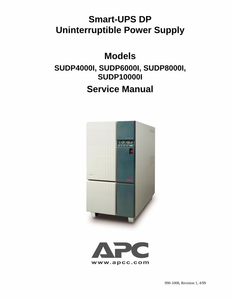
990-1008, Revision 1, 4/99
Smart-UPS DPUninterruptible Power Supply
ModelsSUDP4000I, SUDP6000I, SUDP8000I,
SUDP10000I
Service Manual

Entire contents copyright ©1999 by American Power Conversion. All rights reserved. Reproduction in wholeor in part without permission is prohibited Smart-UPS is a registered trademark of APC. All other trademarksare the property of their respective owners.
990-1008, Revision 1, 4/99
2

990-1008, Revision 1, 4/99
Table of Contents
1. Introduction....................................................................................................................................... 1
2. Functional Description..................................................................................................................... 4
3. Mechanical Layout ........................................................................................................................... 6
4. Main Diagram.................................................................................................................................... 8
5. Spare Part Lists .............................................................................................................................. 10
6. Troubleshooting ............................................................................................................................. 14
7. Changing Modules ......................................................................................................................... 20
8. Test/Adjustments After Repair ...................................................................................................... 41
9. Service Bulletins............................................................................................................................. 48
10. Data Sheet ..................................................................................................................................... 49
11. User Guide (with Installation Guide Included) .......................................................................... 50

990-1008, Revision 1, 4/991
1. Introduction
Smart-UPS DP Service procedures should only be performed by authorized electricians or personnel who havebeen specifically trained to service Smart-UPS DP systems.
Whenever AC and/or DC voltage is applied there may be AC voltage at the UPS output, because the UPS cansupply output power from mains and from its batteries. To avoid equipment damage or personal injury, alwaysassume that there may be voltage at the UPS output.
This unit contains components that are sensitive to electrostatic discharge (ESD). Failing to follow proper ESDprocedures can result in severe damage to electronic components.
WARNING
Make sure that mains supply is switched off before any service is carried out on the Smart-UPS DP.
1.1 Service Policy
The purpose of the Smart-UPS DP system is to protect electronic equipment against breakdowns that can resultfrom an unstable power supply. The Smart-UPS DP system improves data safety, system up-time, andoperational security during normal operations.
It is APC’s policy to deliver reliable, high quality products. This is stated in APC’s quality system.
Quality assurance begins during product development where we design our Smart-UPS DP in consideration of:
• using few components to minimize errors
• choosing the market’s best components from approved suppliers
• following the operating principles, which ensure reliability and operating safety
• making the system easy to install and control
• making the system easy to maintain
• ensuring an environmentally friendly installation
During production, we ensure the quality through a large number of tests of components, modules and systems.Further, education of our production employees and optimizing the production process, enhance productionquality.
It is APC’s goal to make 100% up-time possible for the installations of our customers.
The Smart-UPS DP system is designed for longevity and experience, most APC UPS systems function at least10 years. This, however, requires that the system is checked and maintained regularly. We therefore recommendour customers to follow APC’s maintenance programs.
1.2 A Smart-UPS DP System Must Be Maintained
Even though APC’s systems are designed and produced by the latest and safest technology, all Smart-UPS DPsystems must be maintained.
The system contains components and parts which, in time, will be worn out or have a limited life. These partsmust be checked and, in the course of time, replaced to avoid defects in the system.
APC guaranties delivery of spare parts for all Smart-UPS DP systems for at least 10 years after ending theproduction of the product.
APC recommends a service contract for all Smart-UPS DP installations. A service contract will ensures that theSmart-UPS DP system is always in perfect condition to protect the critical installation against power failure.You can sign up for a service contract with any authorized APC service center.
A service contract includes thorough inspection and test of the system in determined intervals and worn partsand components with limited life will be replaced in time. Furthermore, we ensure the customer against

990-1008, Revision 1, 4/99 2
extraordinary unforeseen expenses, as a service contract can include all necessary extraordinary services andrepairs. For further information, please contact your local APC company, or APC partner.
1.3 Replacement and Maintenance Program
Experience shows that some electromechanical and electrical components are exposed to loads, which causewear and tear and limited life. As a minimum, APC recommends that the following components and parts in theSmart-UPS DP system should be replaced according to the following time periods:
Part Typical Life Time
Fan 3 years
Standard battery 3 years
Long life battery 6 - 8 years
External battery Dependent on chosen type and brand
AC and DC capacitor module 6-9 years
Lithium battery module in controller board 10 years
APC Smart-UPS DP service repairs should only be performed by trained personnel.
In addition, the Smart-UPS DP system should also be inspected once a year by trained personnel for thefollowing items:
• Visual check
• Cleaning, air flow, and environment
• Temperature
• Fuses
• Input and output parameters, plus battery charge current and battery circuit
• Event log, alarms and indicators
• Synchronization
• Circuit breakers
• Fans
• Battery
• Operation
• Accessories and options
• Communication software and interface for computers
990-1008, Revision 1, 4/993
1.4 APC Authorized Service Centers
Each authorized APC service facility in Europe, the USA, the Middle East, and Asia is staffed with trained andexperienced personnel who:
• can be contacted 24 hours a day
• can answer all support calls
• carry a total inventory of spare parts and modules
• have newest and best testing equipment and tools
• have technical documentation for all of APC’s products
In addition, APC service centers offer training and education for customer employees as well as up-to-dateservice manuals.
For more information about Smart-UPS DP products and services, please contact APC or an APC partner.
990-1008, Revision 1, 4/99 4
2. Functional Description
2.1 Functional Description
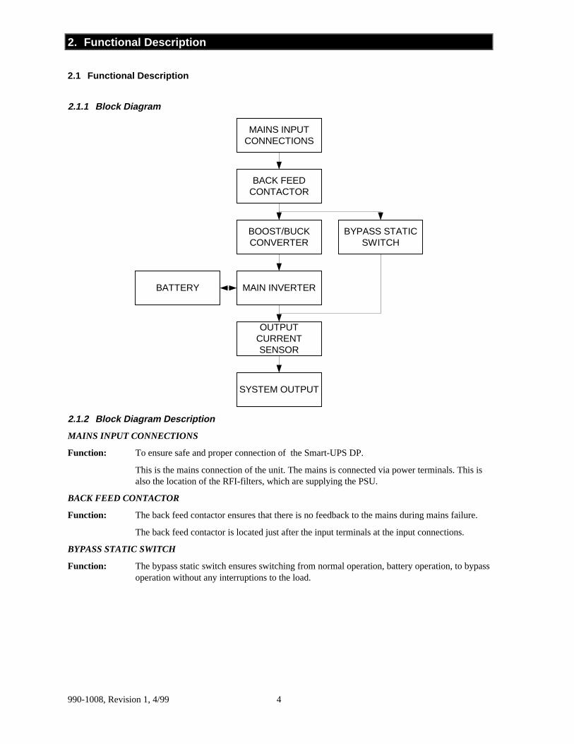
2.1.1 Block Diagram
MAINS INPUTCONNECTIONS
BACK FEEDCONTACTOR
BOOST/BUCKCONVERTER
BYPASS STATICSWITCH
MAIN INVERTERBATTERY
OUTPUTCURRENTSENSOR
SYSTEM OUTPUT
2.1.2 Block Diagram Description
MAINS INPUT CONNECTIONS
Function: To ensure safe and proper connection of the Smart-UPS DP.
This is the mains connection of the unit. The mains is connected via power terminals. This isalso the location of the RFI-filters, which are supplying the PSU.
BACK FEED CONTACTOR
Function: The back feed contactor ensures that there is no feedback to the mains during mains failure.
The back feed contactor is located just after the input terminals at the input connections.
BYPASS STATIC SWITCH
Function: The bypass static switch ensures switching from normal operation, battery operation, to bypassoperation without any interruptions to the load.

990-1008, Revision 1, 4/995
BOOST/BUCK CONVERTER
Function: The boost/buck converter controls the power factor and regulates the input current. Theboost/buck converter makes up for any difference between the output of the Smart-UPS DPand the mains voltage. The boost/buck converter is an electronic choke and works as such.Therefore, the boost/buck converter has a huge internal resistance. Contrary to this, the maininverter is controlled as a constant voltage generator and has, therefore, a very low internalresistance. Together these two inverters protect the load against mains transients. They alsoprotect the mains against harmonic reflections from the load. The control of the boost/buckconverter ensures that the unit is always drawing a sinusoidal current from the mains
MAIN INVERTER
Function: During mains operation, the main inverter is always synchronous to the mains and works as avoltage stabilizer on the output voltage. If the load causes harmonic current on the output, themain inverter will support these currents, hence the control of the boost/buck converterprevents them being taken from the mains. The main inverter helps charge the batteries bypassing the turned over energy from the input to the batteries. During battery operation themain inverter supplies the load with energy from the batteries. During battery operation themain inverter is kept at the desired frequency by means of the internal clock frequency.
BATTERY
Function: The battery stores energy to be used during battery operation. All units have built-in batteries.The batteries are located in the bottom of the unit. More batteries can be added to increase theback-up time.
OUTPUT CURRENT SENSOR
Function: The Output Current Sensor is used to measure the output current in order to indicate if thesystem is overloaded.
SYSTEM OUTPUT
Function: Ensure safe and proper connection of the load.
This is the output of the Smart-UPS DP
990-1008, Revision 1, 4/99 6
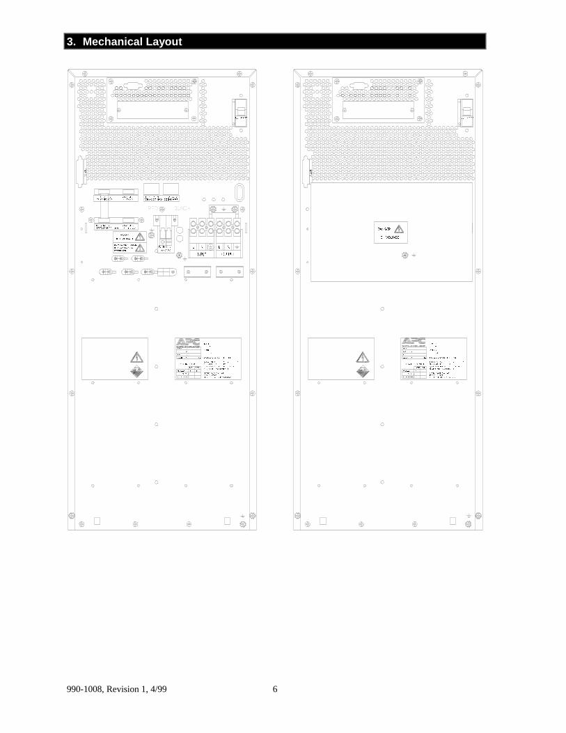
3. Mechanical Layout
)�����0DLQV)�����0DLQV
���������
������
���
�����
����
����
��������
$�'&
$+
0,1��6725('�(1(5*<�7,0(��
287387��
,1387��
$+9�'&��
9�����
���5(3/$&(0(17���5(3/$&(0(17,167$//('
<($50217+5(3/$&(0(17�2)�%$77(5,(6
.*�:(,*+7�6��12��7<3(�3�12��
5(&25'�7+(�'$7(�2)�5(3/$&(0(17�(9(5<�������<($56�5(3/$&(�%$77(5,(6�$7�/($67
120,1$/�%$77(5<�&$3$&,7<8�,�%$77(5<�1250,1$/12��2)�%$77(5,(67<3(�2)�%$77(5,(6
���������
������
���
�����
����
����
��������
$�'&
$+
0,1��6725('�(1(5*<�7,0(��
287387��
,1387��
$+9�'&��
9�����
���5(3/$&(0(17���5(3/$&(0(17,167$//('
<($50217+5(3/$&(0(17�2) �%$77(5,(6
.*�:(,*+7�6��12��7<3(�3�12��
5(&25'�7+(�'$7(�2)�5(3/$&(0(17�(9(5<�������<($56�5(3/$&(�%$77(5,(6�$7�/($67
120,1$/�%$77(5<�&$3$&,7<8�,�%$77(5<�1250,1$/12��2)�%$77(5,(67<3(�2)�%$77(5,(6
/
287387
11/
,1387
(;7(51$/�%$77(5<%()25(�&211(&7,1*�72�6((�,167$//$7,21�,16758&7,216
'$1*(5
'$1*(5
&RP3RUW
%$77��7(03��6(1625)25�(;7(51$/
7(03��6(1625,17(51$/�%$77�
7(03��6(1625)25�%$77(5<
75��7+��6:,7&+)25�(;7(51$/
&RP3RUW
([W��%DWWHU\���9�'&
�������������&20��)$8/7
�������������0%6�&21752/
+,*+�92/7$*( +,*+�92/7$*(
%/$&.5('
990-1008, Revision 1, 4/997
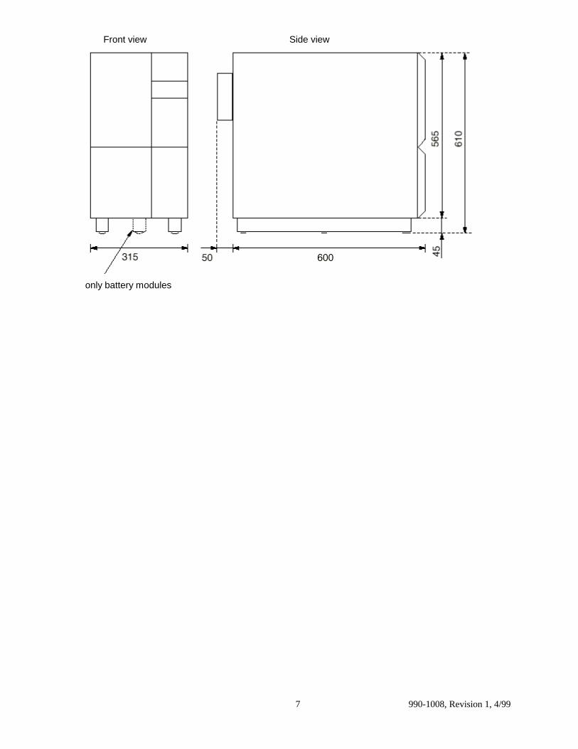
Front view Side view
only battery modules

990-1008, Revision 1, 4/99 8
4. Main Diagram
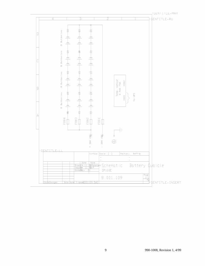
990-1008, Revision 1, 4/999
990-1008, Revision 1, 4/99 10
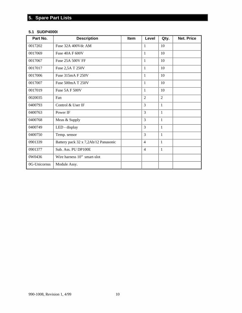
5. Spare Part Lists
5.1 SUDP4000I
Part No. Description Item Level Qty. Net. Price
0017202 Fuse 32A 400Vdc AM 1 10
0017069 Fuse 40A F 600V 1 10
0017067 Fuse 25A 500V FF 1 10
0017017 Fuse 2,5A T 250V 1 10
0017006 Fuse 315mA F 250V 1 10
0017007 Fuse 500mA T 250V 1 10
0017019 Fuse 5A F 500V 1 10
0020035 Fan 2 2
0400793 Control & User IF 3 1
0400763 Power IF 3 1
0400768 Meas & Supply 3 1
0400749 LED - display 3 1
0400750 Temp. sensor 3 1
0901339 Battery pack 32 x 7,2Ah/12 Panasonic 4 1
0901377 Sub. Ass. PU DP100E 4 1
0W0436 Wire harness 10” smart-slot
0G-Unicornss Module Assy.
990-1008, Revision 1, 4/9911
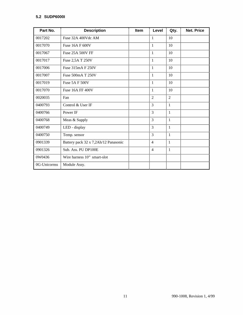
5.2 SUDP6000I
Part No. Description Item Level Qty. Net. Price
0017202 Fuse 32A 400Vdc AM 1 10
0017070 Fuse 16A F 600V 1 10
0017067 Fuse 25A 500V FF 1 10
0017017 Fuse 2,5A T 250V 1 10
0017006 Fuse 315mA F 250V 1 10
0017007 Fuse 500mA T 250V 1 10
0017019 Fuse 5A F 500V 1 10
0017070 Fuse 16A FF 400V 1 10
0020035 Fan 2 2
0400793 Control & User IF 3 1
0400766 Power IF 3 1
0400768 Meas & Supply 3 1
0400749 LED - display 3 1
0400750 Temp. sensor 3 1
0901339 Battery pack 32 x 7,2Ah/12 Panasonic 4 1
0901326 Sub. Ass. PU DP100E 4 1
0W0436 Wire harness 10” smart-slot
0G-Unicornss Module Assy.
990-1008, Revision 1, 4/99 12
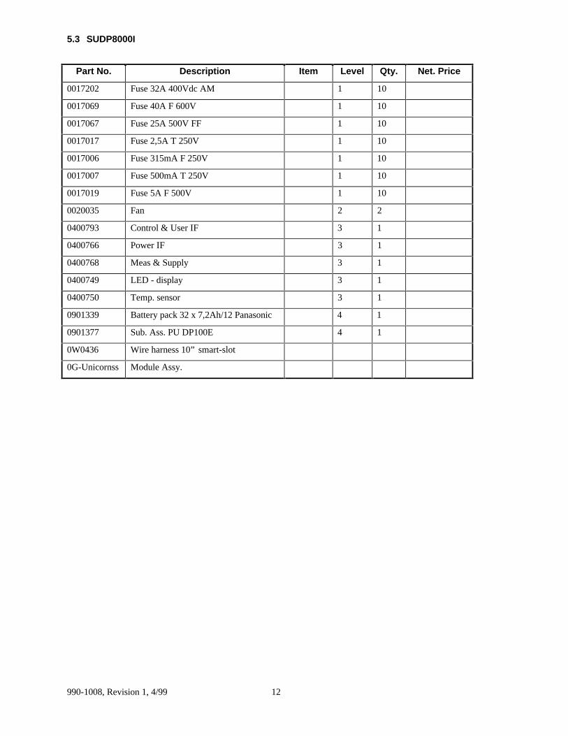
5.3 SUDP8000I
Part No. Description Item Level Qty. Net. Price
0017202 Fuse 32A 400Vdc AM 1 10
0017069 Fuse 40A F 600V 1 10
0017067 Fuse 25A 500V FF 1 10
0017017 Fuse 2,5A T 250V 1 10
0017006 Fuse 315mA F 250V 1 10
0017007 Fuse 500mA T 250V 1 10
0017019 Fuse 5A F 500V 1 10
0020035 Fan 2 2
0400793 Control & User IF 3 1
0400766 Power IF 3 1
0400768 Meas & Supply 3 1
0400749 LED - display 3 1
0400750 Temp. sensor 3 1
0901339 Battery pack 32 x 7,2Ah/12 Panasonic 4 1
0901377 Sub. Ass. PU DP100E 4 1
0W0436 Wire harness 10” smart-slot
0G-Unicornss Module Assy.

990-1008, Revision 1, 4/9913
5.4 SUDP10000I
Part No. Description Item Level Qty. Net. Price
0901312 Sub. Ass. PU DP100E 3 2
0400739 Control & User IF 2 1
0400740 Power IF 2 1
0400751 Meas & Supply 2 1
0400749 LED - display 2 1
0400750 Temp. sensor 2 1
0020035 Fan 1 2
0017202 Fuse 32A 400Vdc AM 1 10
0017069 Fuse 40A F 600V 1 10
0017067 Fuse 25A 500V FF 1 10
0017017 Fuse 2,5A T 250V 1 10
0017006 Fuse 315mA F 250V 1 10
0017007 Fuse 500mA T 250V 1 10
0017019 Fuse 5A F 500V 1 10
0W0436 Wire harness 10” smart-slot
0G-Unicornss Module Assy.
990-1008, Revision 1, 4/99 14
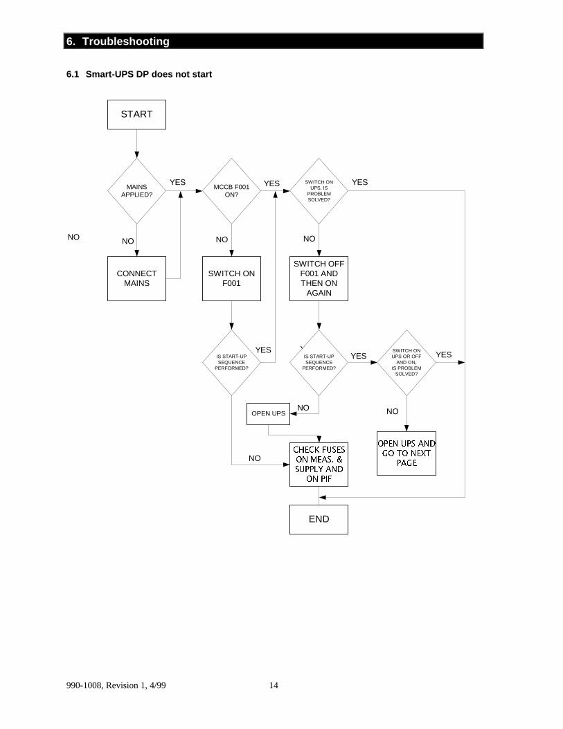
6. Troubleshooting
6.1 Smart-UPS DP does not start
START
CONNECTMAINS
SWITCH ONF001
SWITCH OFFF001 ANDTHEN ON
AGAIN
OPEN UPS
&+(&.�)86(6
21�0($6��
6833/<�$1'
21�3,)
23(1�836�$1'
*2�72�1(;7
3$*(
END
NO
YES
NO
YES YES
NO
YES
YES
YES SWITCH ONUPS, IS
PROBLEMSOLVED?
MAINSAPPLIED?
MCCB F001ON?
IS START-UPSEQUENCE
PERFORMED?
IS START-UPSEQUENCE
PERFORMED?
SWITCH ONUPS OR OFF
AND ON,IS PROBLEM
SOLVED?
YES YES
NO
YESYES YES
NO
NO NO

990-1008, Revision 1, 4/9915
6.2 Smart-UPS DP does not start. Mains connected and start-up sequence is performed.Smart-UPS DP is open.
IS TEMPSWITCH ON HEAT
SINK IN PUMOUNTED AND
OKAY?
START
ARE FANSOPERATING?
IS SIGNAL CABLEBETWEEN
TRANSFORMER ANDUPS MOUNTED?
IS ISOLATIONTRANSFORMER
MOUNTED?
VOLTAGE ONFAN?
MOUNT CABLE
CORRECTFAULT
IS JUMPERMOUNTED ONREAR SIDE OF
UPS?
FAULT INCONTROLLER
CHANGE CABLECORRECT
FAULT
IS TEMP SWITCHIN TRANSFORMER
OKAY?
IS CABLEOKAY?
FAULT IN PSU.CHECK FUSES
ON MEAS. &SUPPLY AND
ON PIF
CHANGEFAN MOUNT
CABLE
CHANGEDISPLAY AND/
OR CABLE
END
YES
DOES ON/OFFBUTTON WORK?
SIGNAL ONCONTROLLER?
YESYES YES YES YES
YES
YES
YES YES
NO
NO
NO NO
NONO
NO NO NO

990-1008, Revision 1, 4/99 16
6.3 Smart-UPS DP only operates 5 seconds after start-up. “Undervoltage Timer” active.
BATTERYFUSES
DEFECTED
CROWBAR HASPROBABLY BEEN
ACTIVATED
CHECK CIRCUITIN CONNECTION
WITH MEASURINGOF CHARGECURRENT,
RELAYS, ANDIGBT’S. CHANGE
FUSES IFNECESSARY.
CHANGE POWERUNIT
CHECK THAT NONE OFTHE PINS ON THE
THREE 64-POLE PLUGSARE BENT AND THAT
CONNECTION IT OKAY.
PROBABLY BLOWNFUSES IN POWER
UNIT(S)
ELSE FAULT IN POWERUNIT AND/OR
CONTROLLER, FUSE ONPIF, OR MEAS. &
SUPPLY
FAULT INCONTROLLER
YES
START
END
DC ONPOWERUNIT?
DC FUSES ONPU OKAY?
INVERTERFUSESOKAY?
CORRECTOUTPUT
VOLTAGE?
YES YES YES
NO NO
NO
NO
990-1008, Revision 1, 4/9917
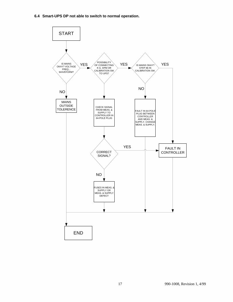
6.4 Smart-UPS DP not able to switch to normal operation.
MAINSOUTSIDE
TOLERENCECHECK SIGNALFROM MEAS. &
SUPPLY TOCONTROLLER iN64-POLE PLUG
FAULT IN 64-POLEPLUG BETWEEN
CONTROLLERAND MEAS. &
SUPPLY. CHANGEMEAS. & SUPPLY.
FAULT INCONTROLLER
FUSES IN MEAS. &SUPPLY OR
MEAS. & SUPPLYDEFECT
START
CORRECTSIGNAL?
END
NO
YES
IS MAINSOKAY? VOLTAGE
FREQ...WAVEFORM?
POSSIBILITYOF CONNECTING
E.G. DPM ORCALIBRATION SW
TO UPS?
IS MAINS OKAY?STEP 86 IN
CALIBRATION SW.
YES YES YES
NO
NO

990-1008, Revision 1, 4/99 18
6.5 Smart-UPS DP is running in normal operation and mounted with Service Bypass Panel.Service Bypass Panel is not operating.
UPS IS NOT ABLETO OPERATE
SERVICE BYPASSPANEL
CHECKFUSES ONMEAS. &SUPPLY
CHECK WIRING FROMUPS TO SERVICE
BYPASS PANEL ANDFUSES INSIDE
SERVICE BYPASSPANEL
START
END
YESDOES UPS SWITCH
TO BYPASS OPERATIONWHEN S002 ON
SERVICE BYPASSPANEL IS PUSHED
IS MAINS WITHIN LIMITSFOR BYPASSOPERATION
IS ITPOSSIBLE TO
SWITCH Q002 TOBYPASS
YES
NO
NO
NO
YES

990-1008, Revision 1, 4/9919
6.6 Loss of UPS-Link communicator
REMOVESMART CARD
OPEN UNIT
REPLACESMARTCARD
CONNECTCABLE(S)
YES NO
UNCONNECTED
CONNECTED
END
START
CHECKCABLE
CONNECTIONS
COMMRESTORED
REPLACEMODULE

990-1008, Revision 1, 4/99 20
7. Changing Modules
This chapter contains instructions for performing the following procedures:
Note:
If the Smart-UPS DP has been installed with a service bypass panel, the load must be switched over tomains before any of the following procedures can be performed.
7.1 Switching off the Smart-UPS DP
7.2 Removing the cover placed above the external connections
7.3 Removing the external DC-supply
7.4 Opening the Smart-UPS DP
7.5 Removing the internal DC-supply
7.6 Removing cables for external units
7.7 Removing the smart slot board chassis
7.8 Removing the controller board
7.9 Removing the power unit board 2 (upper)
7.10 Removing the power unit board 1 (lower)
7.11 Removing the power interface board
7.12 Removing the measuring and supply board
7.13 Removing the batteries
7.14 Removing the LED-board
7.15 Removing the battery temperature sensor board
7.16 Removing the electronic shelf fan
When performing remounting procedures, the appropriate instructions should be reversed.
WARNINGS
Before changing modules or batteries,make sure that mains supply and DC-supply have been switched off.
Remember, the UPS contains static sensitive devices.

990-1008, Revision 1, 4/9921
7.1 Switching Off the Smart-UPS DP
A possible load must be switched off, or switched over to the mains via the service bypass panel.
1. Switch off the Smart-UPS DP on the front of the system.
2. Switch off MCCB (F001) on the rear side of the system.
3. Switch off mains supply to the Smart-UPS DP.
�
�
990-1008, Revision 1, 4/99 22
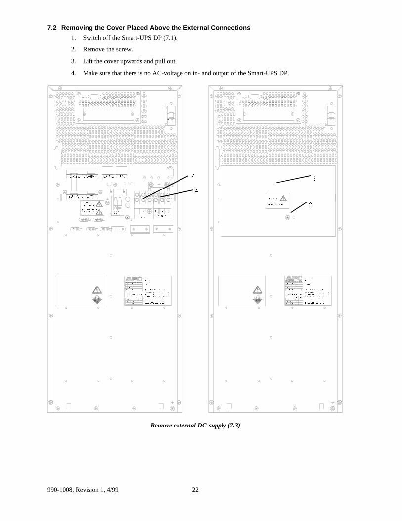
7.2 Removing the Cover Placed Above the External Connections
1. Switch off the Smart-UPS DP (7.1).
2. Remove the screw.
3. Lift the cover upwards and pull out.
4. Make sure that there is no AC-voltage on in- and output of the Smart-UPS DP.
)�����0DLQV)�����0DLQV
���������
������
���
�����
����
����
��������
$�'&
$+
0,1��6725('�(1(5*<�7,0(��
287387��
,1387��
$+9�'&��
9�����
���5(3/$&(0(17���5(3/$&(0(17,167$//('
<($50217+5(3/$&(0(17�2)�%$77(5,(6
.*�:(,*+7�6��12��7<3(�3�12��
5(&25'�7+(�'$7(�2)�5(3/$&(0(17�(9(5<�������<($56�5(3/$&(�%$77(5,(6�$7�/($67
120,1$/�%$77(5<�&$3$&,7<8�,�%$77(5<�1250,1$/12��2)�%$77(5,(67<3(�2)�%$77(5,(6
���������
������
���
�����
����
����
��������
$�'&
$+
0,1��6725('�(1(5*<�7,0(��
287387��
,1387��
$+9�'&��
9�����
���5(3/$&(0(17���5(3/$&(0(17,167$//('
<($50217+5(3/$&(0(17�2) �%$77(5,(6
.*�:(,*+7�6��12��7<3(�3�12��
5(&25'�7+(�'$7(�2)�5(3/$&(0(17�(9(5<�������<($56�5(3/$&(�%$77(5,(6�$7�/($67
120,1$/�%$77(5<�&$3$&,7<8�,�%$77(5<�1250,1$/12��2)�%$77(5,(67<3(�2)�%$77(5,(6
/
287387
11/
,1387
(;7(51$/�%$77(5<%()25(�&211(&7,1*�72�6((�,167$//$7,21�,16758&7,216
'$1*(5
'$1*(5
&RP3RUW
%$77��7(03��6(1625)25�(;7(51$/
7(03��6(1625,17(51$/�%$77�
7(03��6(1625)25�%$77(5<
75��7+��6:,7&+)25�(;7(51$/
&RP3RUW
([W��%DWWHU\���9�'&
�������������&20��)$8/7
�������������0%6�&21752/
+,*+�92/7$*( +,*+�92/7$*(
%/$&.5('
�
��
�
Remove external DC-supply (7.3)
990-1008, Revision 1, 4/9923
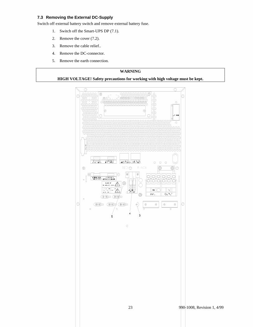
7.3 Removing the External DC-Supply
Switch off external battery switch and remove external battery fuse.
1. Switch off the Smart-UPS DP (7.1).
2. Remove the cover (7.2).
3. Remove the cable relief..
4. Remove the DC-connector.
5. Remove the earth connection.
WARNING
HIGH VOLTAGE! Safety precautions for working with high voltage must be kept.
)�����0DLQV
/
287387
11/
,1387
(;7(51$/�%$77(5<%()25(�&211(&7,1*�72�6((�,167$//$7,21�,16758&7,216
'$1*(5
%$77��7(03��6(1625)25�(;7(51$/
7(03��6(1625,17(51$/�%$77�
7(03��6(1625)25�%$77(5<
75��7+��6:,7&+)25�(;7(51$/
&RP3RUW
([W��%DWWHU\���9�'&
�������������&20��)$8/7
�������������0%6�&21752/
+,*+�92/7$*(
%/$&.5('
�
��

990-1008, Revision 1, 4/99 24
7.4 Opening the Smart-UPS DP
1. Switch off the Smart-UPS DP (7.1).
2. Remove the cover (7.2).
3. Remove the external DC-Supply (7.3).
4. Remove the screws on rear side of the system that hold the cover on.
5. Remove the cover by sliding the rear end of the cover upwards and back.
WARNING
Take care not to drop the front edge of the cover into the power unit.
� �
� �
��
� �
� �
�
�

990-1008, Revision 1, 4/9925
7.5 Removing the Internal DC-Supply
1. Switch off the Smart-UPS DP (7.1).
2. Remove the cover (7.2).
3. Remove the external DC-Supply (7.3).
4. Open the Smart-UPS DP (7.4).
5. Remove the battery plug from the middle plate below the electronic shelf.
6. Using isolated fuse tongs, remove the battery fuses.
WARNING
HIGH VOLTAGE! Safety precautions for working with high voltage must be kept.
� ��
�
7. Make sure (by measuring) that there is no DC-voltage between X004 (DC 438V+) and X005 (DC438V-) on upper power unit.
8. Make sure (by measuring connector X025) that there is no voltage on the capacitors on the powerunit.
WARNING
The capacitors have a long discharging time (5 min.)
;���;���;���
� � �
990-1008, Revision 1, 4/99 26
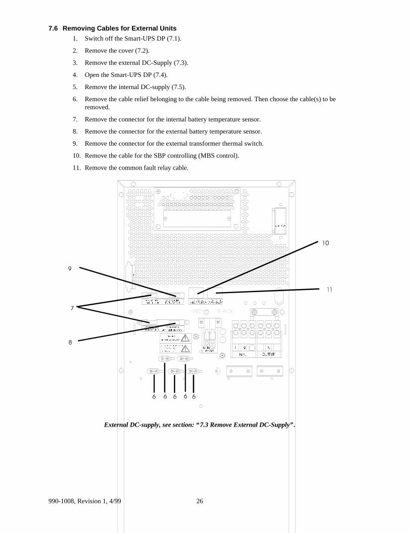
7.6 Removing Cables for External Units
1. Switch off the Smart-UPS DP (7.1).
2. Remove the cover (7.2).
3. Remove the external DC-Supply (7.3).
4. Open the Smart-UPS DP (7.4).
5. Remove the internal DC-supply (7.5).
6. Remove the cable relief belonging to the cable being removed. Then choose the cable(s) to beremoved.
7. Remove the connector for the internal battery temperature sensor.
8. Remove the connector for the external battery temperature sensor.
9. Remove the connector for the external transformer thermal switch.
10. Remove the cable for the SBP controlling (MBS control).
11. Remove the common fault relay cable.
)�����0DLQV
/
287387
11/
,1387
(;7(51$/�%$77(5<%()25(�&211(&7,1*�72�6((�,167$//$7,21�,16758&7,216
'$1*(5
%$77��7(03��6(1625)25�(;7(51$/
7(03��6(1625,17(51$/�%$77�
7(03��6(1625)25�%$77(5<
75��7+��6:,7&+)25�(;7(51$/
&RP3RUW
([W��%DWWHU\���9�'&
�������������&20��)$8/7
�������������0%6�&21752/
+,*+�92/7$*(
%/$&.5('
�
�
�
��
� � � ��
External DC-supply, see section: “7.3 Remove External DC-Supply”.
990-1008, Revision 1, 4/9927
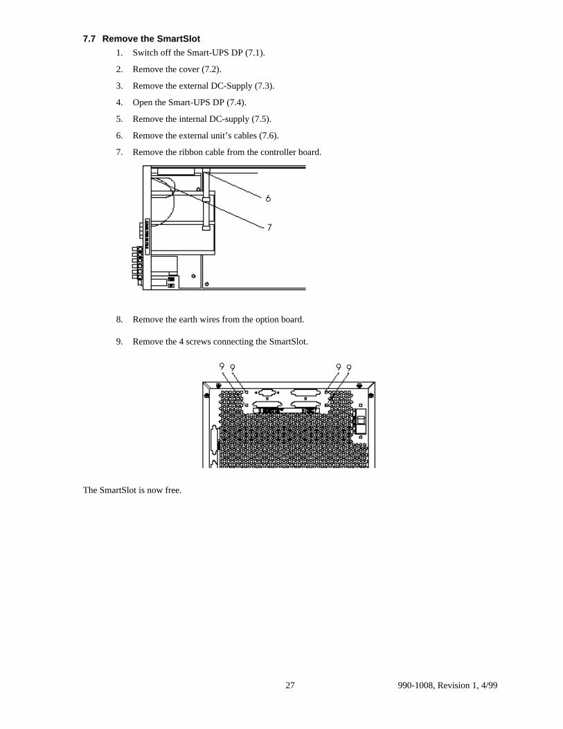
7.7 Remove the SmartSlot
1. Switch off the Smart-UPS DP (7.1).
2. Remove the cover (7.2).
3. Remove the external DC-Supply (7.3).
4. Open the Smart-UPS DP (7.4).
5. Remove the internal DC-supply (7.5).
6. Remove the external unit’s cables (7.6).
7. Remove the ribbon cable from the controller board.
�
�
8. Remove the earth wires from the option board.
9. Remove the 4 screws connecting the SmartSlot.
� � � �
The SmartSlot is now free.

990-1008, Revision 1, 4/99 28
7.8 Removing the Controller Board
1. Switch off the Smart-UPS DP (7.1).
2. Remove the cover (7.2).
3. Remove the external DC-Supply (7.3).
4. Open the Smart-UPS DP (7.4).
5. Remove the internal DC-supply (7.5).
6. Remove the external unit’s cables (7.6).
7. Remove the SmartSlot (7.7)
8. Remove the 2 (4) screws that connect the CU-board to the PU-board(s).
�� � �
9. Remove the LED-display ribbon cable.
10. Remove the options ribbon cable.
11. Remove the grounding wire from the chassis.
� �� ��
990-1008, Revision 1, 4/9929
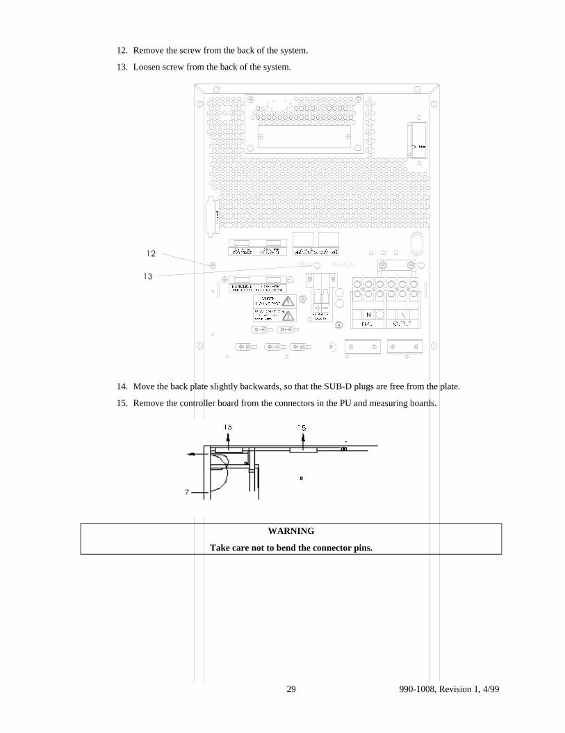
12. Remove the screw from the back of the system.
13. Loosen screw from the back of the system.
)�����0DLQV
/
287387
11/
,1387
(;7(51$/�%$77(5<%()25(�&211(&7,1*�72�6((�,167$//$7,21�,16758&7,216
'$1*(5
%$77��7(03��6(1625)25�(;7(51$/
7(03��6(1625,17(51$/�%$77�
7(03��6(1625)25�%$77(5<
75��7+��6:,7&+)25�(;7(51$/
&RP3RUW
([W��%DWWHU\���9�'&
�������������&20��)$8/7
�������������0%6�&21752/
+,*+�92/7$*(
%/$&.5('
��
��
14. Move the back plate slightly backwards, so that the SUB-D plugs are free from the plate.
15. Remove the controller board from the connectors in the PU and measuring boards.
�� ��
WARNING
Take care not to bend the connector pins.

990-1008, Revision 1, 4/99 30
7.9 Removing the Power Unit Board 2 (Upper)
1. Switch off the Smart-UPS DP (7.1).
2. Remove the cover (7.2).
3. Remove the external DC-Supply (7.3).
4. Open the Smart-UPS DP (7.4).
5. Remove the internal DC-supply (7.5).
6. Remove any cables for external units (7.6).
7. Remove the SmartSlot (7.7).
8. Remove the controller board (7.8).
9. Remove the wires on the power unit terminals X004, X005, X006, X022, X008, and X001, as wellas the connector for the fan shelf at X003 A, B, or C.
10. Remove the cover plate for heat sink.
1010x00x-008 10 10 10 X008
X006X001X005
X022 X004
X003BX003AX003C
11. Remove the screws that connect the PU-board.
12. Remove the stay at fan.
1111 11 11
11 11 11
12
The board is now free.
990-1008, Revision 1, 4/9931
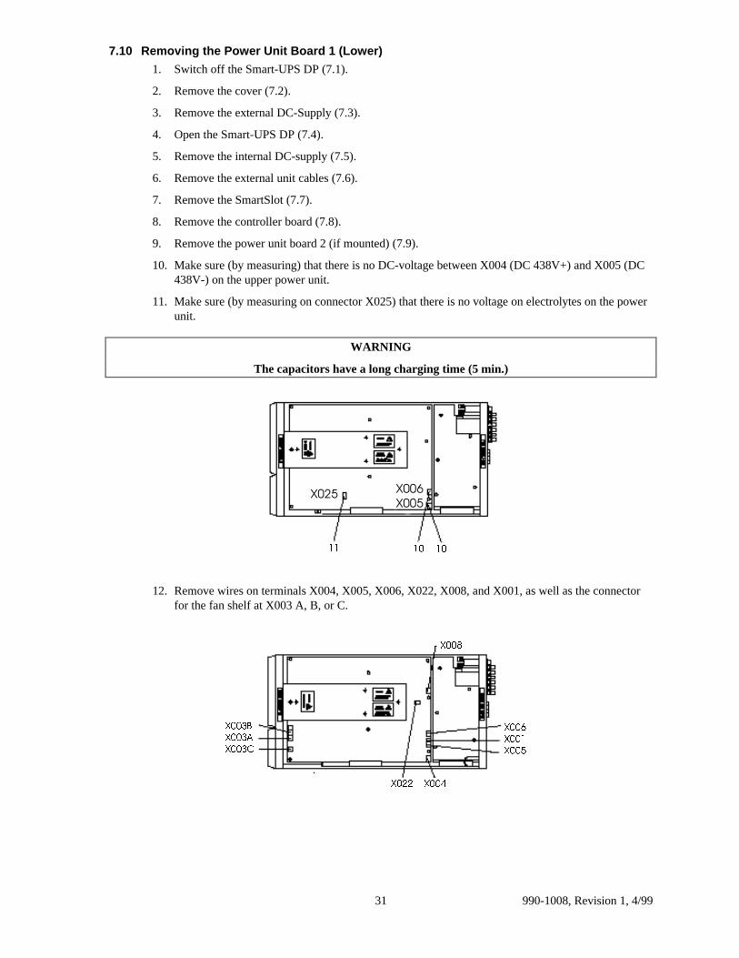
7.10 Removing the Power Unit Board 1 (Lower)
1. Switch off the Smart-UPS DP (7.1).
2. Remove the cover (7.2).
3. Remove the external DC-Supply (7.3).
4. Open the Smart-UPS DP (7.4).
5. Remove the internal DC-supply (7.5).
6. Remove the external unit cables (7.6).
7. Remove the SmartSlot (7.7).
8. Remove the controller board (7.8).
9. Remove the power unit board 2 (if mounted) (7.9).
10. Make sure (by measuring) that there is no DC-voltage between X004 (DC 438V+) and X005 (DC438V-) on the upper power unit.
11. Make sure (by measuring on connector X025) that there is no voltage on electrolytes on the powerunit.
WARNING
The capacitors have a long charging time (5 min.)
;��� ;���;���
�� ����
12. Remove wires on terminals X004, X005, X006, X022, X008, and X001, as well as the connectorfor the fan shelf at X003 A, B, or C.
;���
;���&
;���$
;���%
;���;���
;���
;���
;���
990-1008, Revision 1, 4/99 32
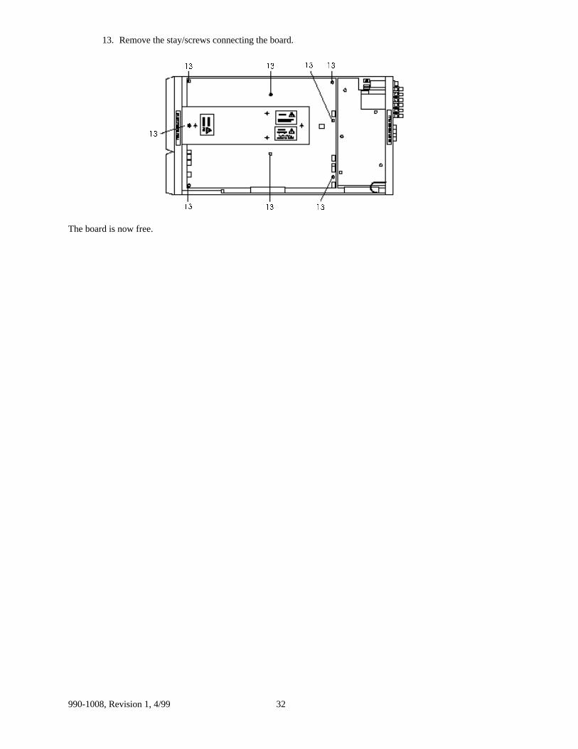
13. Remove the stay/screws connecting the board.
����
��
�� �� ��
��
��
��
The board is now free.
990-1008, Revision 1, 4/9933
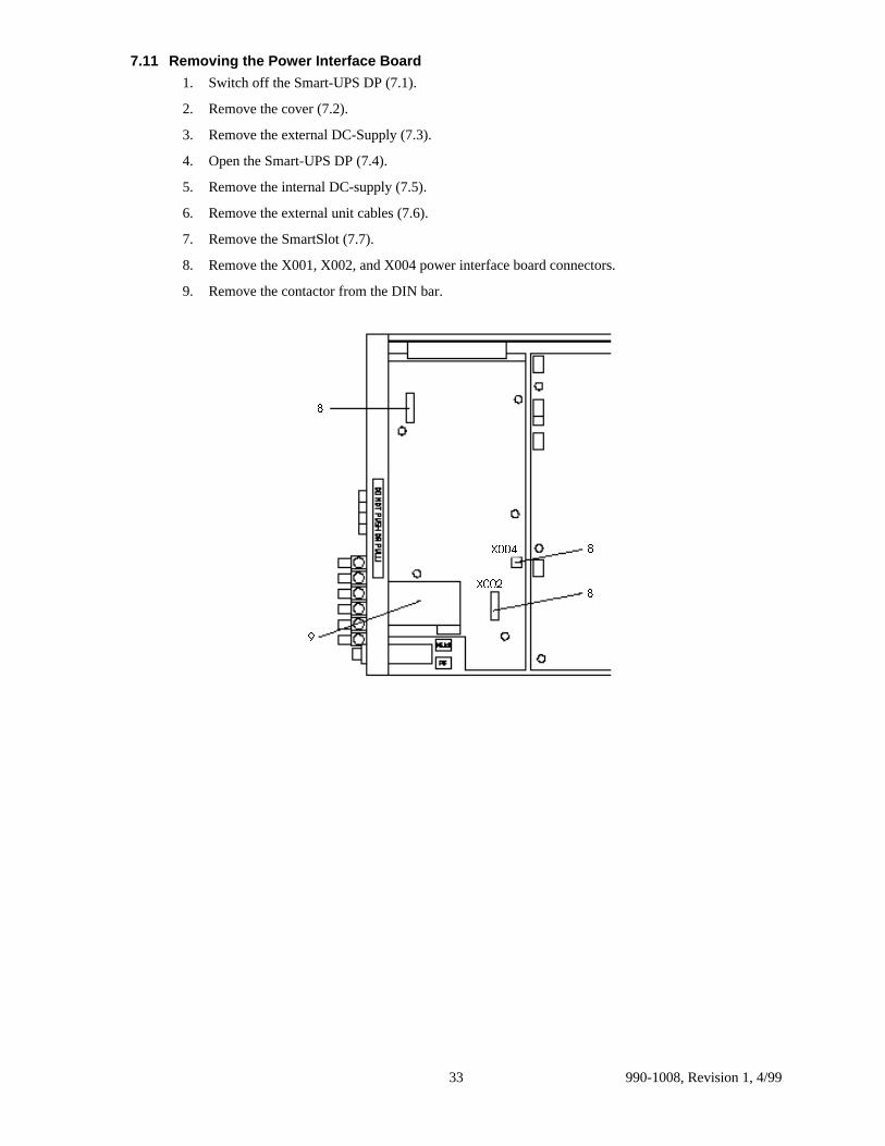
7.11 Removing the Power Interface Board
1. Switch off the Smart-UPS DP (7.1).
2. Remove the cover (7.2).
3. Remove the external DC-Supply (7.3).
4. Open the Smart-UPS DP (7.4).
5. Remove the internal DC-supply (7.5).
6. Remove the external unit cables (7.6).
7. Remove the SmartSlot (7.7).
8. Remove the X001, X002, and X004 power interface board connectors.
9. Remove the contactor from the DIN bar.
;���
;���
�
�
�
�
990-1008, Revision 1, 4/99 34
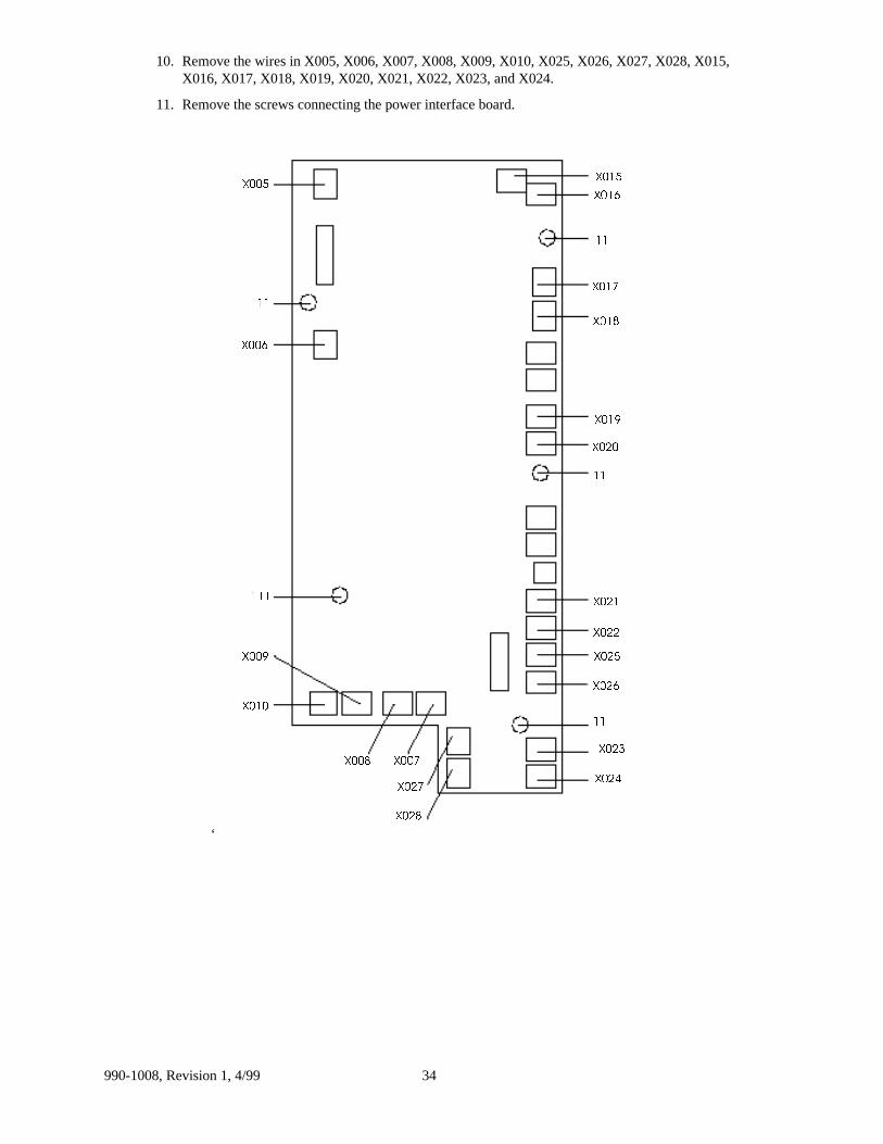
10. Remove the wires in X005, X006, X007, X008, X009, X010, X025, X026, X027, X028, X015,X016, X017, X018, X019, X020, X021, X022, X023, and X024.
11. Remove the screws connecting the power interface board.
‘
;���
��
;���
;���
;���
;��� ;���
;���
;���
;���
;���
��
;���
;���
;���
;���
��
;���
;���
;���
;���
��
;���
;���
��

990-1008, Revision 1, 4/9935
7.12 Removing the Measuring and Supply Board
1. Switch off the Smart-UPS DP (7.1).
2. Remove the cover (7.2).
3. Remove the external DC-Supply (7.3).
4. Open the Smart-UPS DP (7.4).
5. Remove the internal DC-supply (7.5).
6. Remove the external unit cables (7.6).
7. Remove the SmartSlot (7.7).
8. Remove the controller board (7.8).
9. Remove the power interface board (7.11).
10. Remove the stay.
11. Remove the X005 and X006 connectors.
��
��
��
��
��
;���
;���

990-1008, Revision 1, 4/99 36
7.13 Removing the Batteries
WARNING: HIGH VOLTAGE
Safety precautions for working with high voltage must be kept.
1. Switch off the Smart-UPS DP (7.1).
2. Remove the cover (7.2).
3. Remove the external DC-Supply (7.3).
4. Open the Smart-UPS DP (7.4).
5. Remove the internal DC-supply (7.5).
6. Move the shelf above the upper battery slightly upwards and pull it out.
�
7. Remove the interconnection wire between the two center batteries.
8. Remove the two outermost battery cables on the battery set.
�
��
990-1008, Revision 1, 4/9937
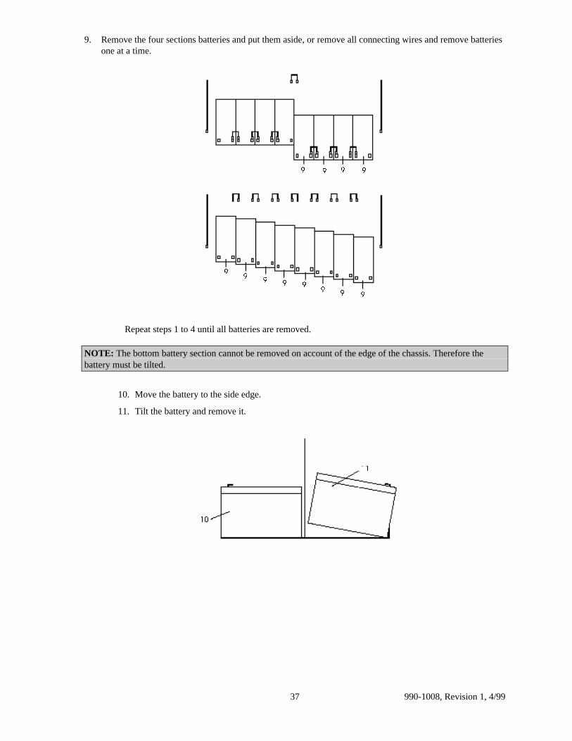
9. Remove the four sections batteries and put them aside, or remove all connecting wires and remove batteriesone at a time.
��
�� �
�� �
� � � �
Repeat steps 1 to 4 until all batteries are removed.
NOTE: The bottom battery section cannot be removed on account of the edge of the chassis. Therefore thebattery must be tilted.
10. Move the battery to the side edge.
11. Tilt the battery and remove it.
��
��
990-1008, Revision 1, 4/99 38
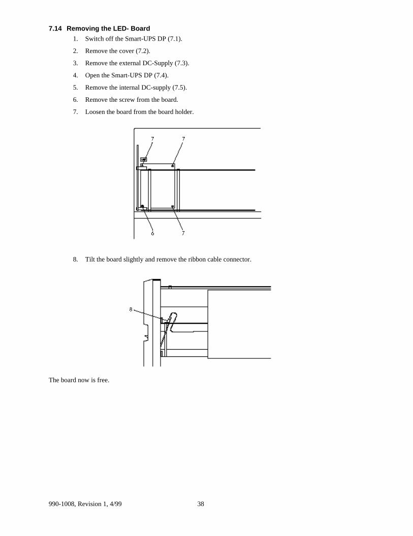
7.14 Removing the LED- Board
1. Switch off the Smart-UPS DP (7.1).
2. Remove the cover (7.2).
3. Remove the external DC-Supply (7.3).
4. Open the Smart-UPS DP (7.4).
5. Remove the internal DC-supply (7.5).
6. Remove the screw from the board.
7. Loosen the board from the board holder.
�
��
�
8. Tilt the board slightly and remove the ribbon cable connector.
�
The board now is free.
990-1008, Revision 1, 4/9939
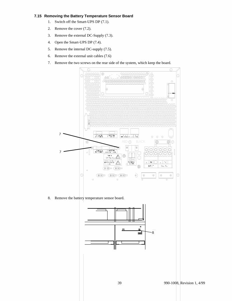
7.15 Removing the Battery Temperature Sensor Board
1. Switch off the Smart-UPS DP (7.1).
2. Remove the cover (7.2).
3. Remove the external DC-Supply (7.3).
4. Open the Smart-UPS DP (7.4).
5. Remove the internal DC-supply (7.5).
6. Remove the external unit cables (7.6)
7. Remove the two screws on the rear side of the system, which keep the board.
)�����0DLQV
/
287387
11/
,1387
(;7(51$/�%$77(5<%()25(�&211(&7,1*�72�6((�,167$//$7,21�,16758&7,216
'$1*(5
%$77��7(03��6(1625)25�(;7(51$/
7(03��6(1625,17(51$/�%$77�
7(03��6(1625)25�%$77(5<
75��7+��6:,7&+)25�(;7(51$/
&RP3RUW
([W��%DWWHU\���9�'&
�������������&20��)$8/7
�������������0%6�&21752/
+,*+�92/7$*(
%/$&.5('
�
�
8. Remove the battery temperature sensor board.
8
990-1008, Revision 1, 4/99 40
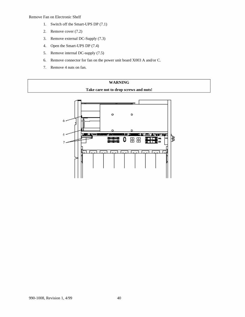
Remove Fan on Electronic Shelf
1. Switch off the Smart-UPS DP (7.1)
2. Remove cover (7.2)
3. Remove external DC-Supply (7.3)
4. Open the Smart-UPS DP (7.4)
5. Remove internal DC-supply (7.5)
6. Remove connector for fan on the power unit board X003 A and/or C.
7. Remove 4 nuts on fan.
WARNING
Take care not to drop screws and nuts!
�
�
�
990-1008, Revision 1, 4/9941
8. Test/Adjustments After Repair8.1 Test/Adjustments After Repair
Calibration of Smart-UPS DP Smart-UPS DP requires the following equipment:
• PC containing calibration software as well as calibration interface.
• Load, meaning both resistive load, SMPS load, as well as transformer.
• Voltmeter.
• Ammeter, possibly a current clamp.
• Scope, possibly a thermometer on account of temperature sensor.
Step refers to Calibration Software.
(Test Smart-UPS DP General, 7.100.542 and Step Description MPU_CAL1, 7.000.854GB)
If the calibration has to take place by the customer, there may be a problem with DC-Imbalance, becausenormally you would not bring along a transformer. The current limit may as well be difficult to calibrate.
Please test all points, or as many as possible.
8.2 Test of Smart-UPS DP in Connection with Service
Serial No.: Rep. No.:
Settings:
In/Output voltage
In/Output frequency
Battery capacity
Operational mode (DP/Economy)
Remote shutdown (ON/OFF)
Remote shutdown polarity (Pos./Neg.)
Remote shutdown time (30/120 sec.)
Auto restart (ON/OFF)
Spare tank (ON/OFF)
Spare tank level (0/25/50%)
990-1008, Revision 1, 4/99 42
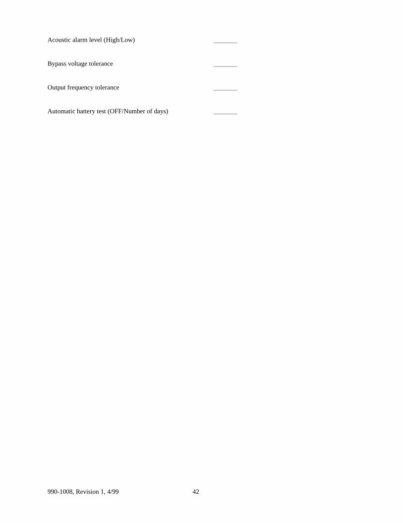
Acoustic alarm level (High/Low)
Bypass voltage tolerance
Output frequency tolerance
Automatic battery test (OFF/Number of days)
990-1008, Revision 1, 4/9943
Checked (ä)
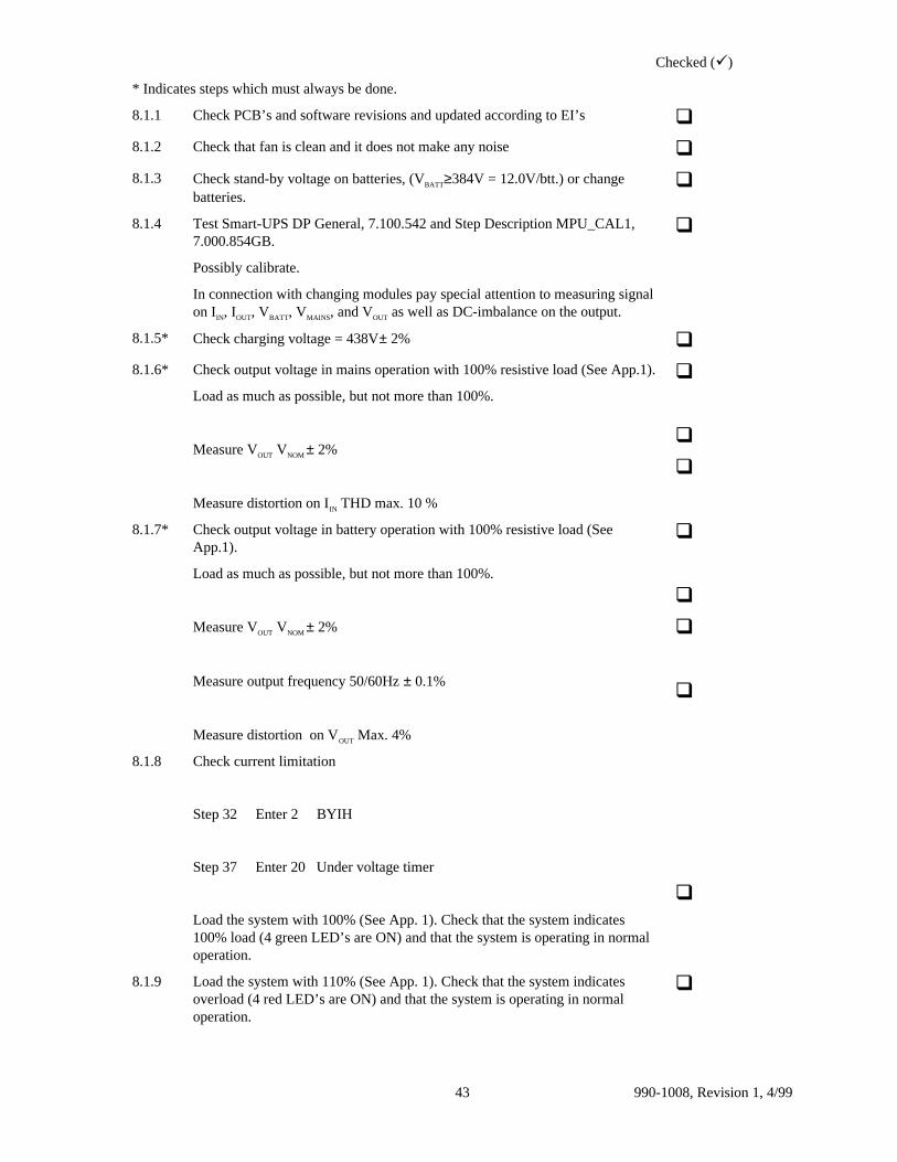
* Indicates steps which must always be done.
8.1.1 Check PCB’s and software revisions and updated according to EI’s q8.1.2 Check that fan is clean and it does not make any noise q8.1.3 Check stand-by voltage on batteries, (VBATT≥384V = 12.0V/btt.) or change
batteries.q
8.1.4 Test Smart-UPS DP General, 7.100.542 and Step Description MPU_CAL1,7.000.854GB.
Possibly calibrate.
In connection with changing modules pay special attention to measuring signalon IIN, IOUT, VBATT, VMAINS, and VOUT as well as DC-imbalance on the output.
q
8.1.5* Check charging voltage = 438V± 2% q8.1.6* Check output voltage in mains operation with 100% resistive load (See App.1).
Load as much as possible, but not more than 100%.
Measure VOUT VNOM ± 2%
Measure distortion on IIN THD max. 10 %
q
q
q
8.1.7* Check output voltage in battery operation with 100% resistive load (SeeApp.1).
Load as much as possible, but not more than 100%.
Measure VOUT VNOM ± 2%
Measure output frequency 50/60Hz ± 0.1%
Measure distortion on VOUT Max. 4%
q
q
q
q
8.1.8 Check current limitation
Step 32 Enter 2 BYIH
Step 37 Enter 20 Under voltage timer
Load the system with 100% (See App. 1). Check that the system indicates100% load (4 green LED’s are ON) and that the system is operating in normaloperation.
q
8.1.9 Load the system with 110% (See App. 1). Check that the system indicatesoverload (4 red LED’s are ON) and that the system is operating in normaloperation.
q

990-1008, Revision 1, 4/99 44
8.1.10 Load the system with 165% (See App.1). Check that:
• the system switches to battery operation.
• the output current is reduced to 155% +4/-2% (See App.1).
• After 30 seconds (±5 sec.) the output current is further reduced to 105 %+4/-2% (See App.1).
• The system switches off after 5 seconds.
q
q
q
q
8.1.11 Switch off the load.
Step 32 Enter 1 BYON
Step 37 Enter 5
8.1.12 Check lower switching off level -18% (See App.1). q8.1.13 Check lower switching on level -9% (See App.1). q8.1.14 Check upper switching off level + 12% (See App.1). q8.1.15 Check upper switching on level +6.5% (See App.1). q8.1.16* Check bypass with 100% resistive load (Apply S400 to CU)
Load as much as possible, but not more than 100%.
Measure VOUT±5% (See App.1).q
8.1.17* Check relay functions on COM-port by means of test-box. q8.1.18 Check remote shutdown by means of test-box.
(Smart-UPS DP in battery operation).
q

990-1008, Revision 1, 4/9945
8.3 Test of Options
Checked (ä)
8.2.1 Check Multicom; communication is tested by means of DP-Monitor (datatransmitted).
q
8.2.2 Check Compower 5/12V.
• 5V Compower = 5V±0.3V
• 12V Compower = 10V ±1.2V
q
q
8.2.3 Check remote display driver, mount remote display, and check the indicators. q8.2.4 Check transformer module, fan + thermal switch OK. q8.2.5* Concerned calibration steps:
Step 18 ALON Alarm ON
Step 32 BYON Bypass ON
Step 33 NOBI No Burn-in
Step 35 TCMP Temperature compensation of chargingvoltage
Step 37 5 Under voltage timer (seconds)
Step 40 HDIP Hardware switches active
Step 30 BATF → Enter 1 Reset battery monitor
Step 20 Enter the output voltage stated in settings.
NOTE! If the output voltage has been changed during test, all AC levels are set atdefault. In that case it is necessary to check that the settings correspond with thesettings stated in the test report.
Step 48 Switch the system into the operational mode stated in settings.
Enter the correct settings for the system.
990-1008, Revision 1, 4/99 46
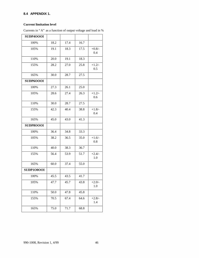
8.4 APPENDIX 1.
Current limitation level
Currents in “ A” as a function of output voltage and load in %
SUDP4OOOI
100% 18.2 17.4 16.7
105% 19.1 18.3 17.5 +0.8/-0.4
110% 20.0 19.1 18.3
155% 28.2 27.0 25.8 +1.2/-0.5
165% 30.0 28.7 27.5
SUDP6OOOI
100% 27.3 26.1 25.0
105% 28.6 27.4 26.3 +1.2/-0.6
110% 30.0 28.7 27.5
155% 42.3 40.4 38.8 +1.8/-0.4
165% 45.0 43.0 41.3
SUDP8OOOI
100% 36.4 34.8 33.3
105% 38.2 36.5 35.0 +1.6/-0.8
110% 40.0 38.3 36.7
155% 56.4 53.9 51.7 +2.4/-1.0
165% 60.0 37.4 55.0
SUDP1O0OOI
100% 45.5 43.5 41.7
105% 47.7 45.7 43.8 +2.0/-1.0
110% 50.0 47.8 45.8
155% 70.5 67.4 64.6 +2.8/-1.4
165% 75.0 71.7 68.8
990-1008, Revision 1, 4/9947
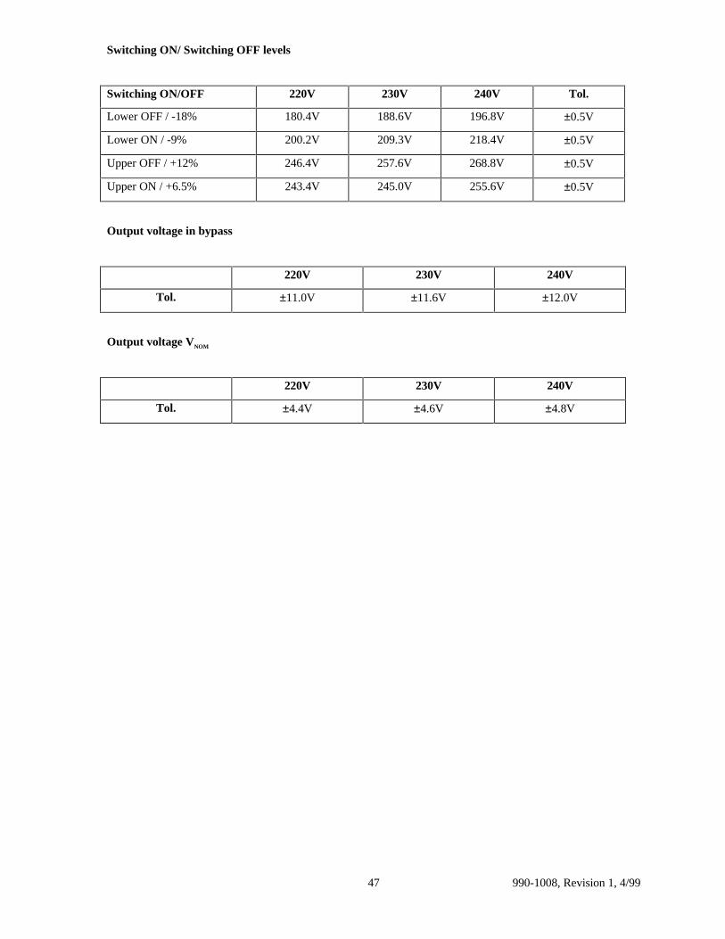
Switching ON/ Switching OFF levels
Switching ON/OFF 220V 230V 240V Tol.
Lower OFF / -18% 180.4V 188.6V 196.8V ±0.5V
Lower ON / -9% 200.2V 209.3V 218.4V ±0.5V
Upper OFF / +12% 246.4V 257.6V 268.8V ±0.5V
Upper ON / +6.5% 243.4V 245.0V 255.6V ±0.5V
Output voltage in bypass
220V 230V 240V
Tol. ±11.0V ±11.6V ±12.0V
Output voltage VNOM
220V 230V 240V
Tol. ±4.4V ±4.6V ±4.8V

990-1008, Revision 1, 4/99 48
9. Service Bulletins

990-1008, Revision 1, 4/9949
10. Data Sheet
Acrobat Document
990-1008, Revision 1, 4/99 50
11. User Guide (with Installation Guide Included)
��������H�GRF


![INDEX [meanwell.com]meanwell.com/Upload/PDF/meanwell_LED.pdf · APC-8, APC-12, APC-16, APC-25, APC-35 3 APV-8E, APV-12E, APV-16E 4 APC-8E, APC-12E, APC-16E LP ... Over voltage protection](https://static.fdocuments.us/doc/165x107/5b619e107f8b9a40488c919f/index-apc-8-apc-12-apc-16-apc-25-apc-35-3-apv-8e-apv-12e-apv-16e-4.jpg)