ap1611112 interrupt response time - Infineon
22
Microcontrollers A pplication Note V1.2 2009-09 XC2000 Family A P16111 Interrupt Response Time of the XC2000 Family
Transcript of ap1611112 interrupt response time - Infineon

Microcontrol lers
Appl icat ion Note V1.2 2009-09
XC2000 Family
AP16111 Interrupt Response Time of the XC2000 Family

Edition 2009-09 Published by Infineon Technologies AG 81726 Munich, Germany © 2009 Infineon Technologies AG All Rights Reserved.
LEGAL DISCLAIMER THE INFORMATION GIVEN IN THIS APPLICATION NOTE IS GIVEN AS A HINT FOR THE IMPLEMENTATION OF THE INFINEON TECHNOLOGIES COMPONENT ONLY AND SHALL NOT BE REGARDED AS ANY DESCRIPTION OR WARRANTY OF A CERTAIN FUNCTIONALITY, CONDITION OR QUALITY OF THE INFINEON TECHNOLOGIES COMPONENT. THE RECIPIENT OF THIS APPLICATION NOTE MUST VERIFY ANY FUNCTION DESCRIBED HEREIN IN THE REAL APPLICATION. INFINEON TECHNOLOGIES HEREBY DISCLAIMS ANY AND ALL WARRANTIES AND LIABILITIES OF ANY KIND (INCLUDING WITHOUT LIMITATION WARRANTIES OF NON-INFRINGEMENT OF INTELLECTUAL PROPERTY RIGHTS OF ANY THIRD PARTY) WITH RESPECT TO ANY AND ALL INFORMATION GIVEN IN THIS APPLICATION NOTE.
Information For further information on technology, delivery terms and conditions and prices, please contact the nearest Infineon Technologies Office (www.infineon.com).
Warnings Due to technical requirements, components may contain dangerous substances. For information on the types in question, please contact the nearest Infineon Technologies Office. Infineon Technologies components may be used in life-support devices or systems only with the express written approval of Infineon Technologies, if a failure of such components can reasonably be expected to cause the failure of that life-support device or system or to affect the safety or effectiveness of that device or system. Life support devices or systems are intended to be implanted in the human body or to support and/or maintain and sustain and/or protect human life. If they fail, it is reasonable to assume that the health of the user or other persons may be endangered.

AP16111 Interrupt Response Time of the XC2000 Family
Application Note 3 V1.2, 2009-09
XC2000/XE166 Family Revision History: V1.2, 2009-09 Previous Version: V1.1 Page Subjects (major changes since last revision) 6 ff Replaced “Fast External Interrupt” by “External Request” 7 Adjusted peripheral set and timing to match XC2000/XE166 11 Added cycle numbers to list of delay conditions 14 Removed the limitation for DAvE which now supports interrupt latency optimization
We Listen to Your Comments Is there any information in this document that you feel is wrong, unclear or missing? Your feedback will help us to continuously improve the quality of this document. Please send your proposal (including a reference to this document) to: [email protected]

AP16111 Interrupt Response Time of the XC2000 Family Table of Contents
Application Note 4 V1.2, 2009-09
Table of Contents
1 Introduction ........................................................................................................................................5 1.1 General Conditions ..............................................................................................................................5 2 Interrupt Response Time...................................................................................................................6 2.1 Definition of Interrupt Response Time .................................................................................................6 2.2 Interrupt Flow .......................................................................................................................................6 2.2.1 Peripheral / External Interrupt ..............................................................................................................7 2.2.2 Interrupt Controller / Arbitration............................................................................................................8 2.2.3 CPU Core .............................................................................................................................................9 2.3 Summary ............................................................................................................................................11 3 Configuration of the Interrupt Handler ..........................................................................................12 3.1 Potentials to Influence the Interrupt Response Time.........................................................................12 3.1.1 Jump Table Cache (Fast Interrupt) ....................................................................................................12 3.1.2 Fast Bank Switching...........................................................................................................................13 3.2 C-Compiler and Configuration of the Interrupt Handler .....................................................................14 3.2.1 Keil .....................................................................................................................................................14 3.2.2 Tasking...............................................................................................................................................16 3.2.2.1 Tasking C166 Toolset ........................................................................................................................16 3.2.2.2 Tasking VX C166 Toolset ..................................................................................................................19 4 Conclusion........................................................................................................................................21

AP16111 Interrupt Response Time of the XC2000 Family
Introduction
Application Note 5 V1.2, 2009-09
1 Introduction The architecture of the XC2000 family supports several mechanisms for fast and flexible response to service requests from various sources internal or external to the microcontroller. Different kinds are handled in a similar way: • Interrupts generated by the Interrupt Controller (ITC). • DMA transfer issued by the Peripheral Event Controller (PEC). • Traps caused by the Trap instruction or issued by faults or specific system states. The XC2000 family fits perfectly in embedded applications. The target of this application note is to supply detailed information about the real time capabilities of the interrupt architecture.
For more detailed information about the functionality of the interrupt architecture please refer to the corresponding user manual.
1.1 General Conditions The following calculations are only valid for the conditions below: • All memory accesses are done without delay.
Code and Interrupt Vector Table located in a fast internal program memory (PSRAM). The stack is located in fast internal data memory (DSRAM).
• No previous interrupt request is still processed. • No stall or cancellation condition of the pipeline is valid.

AP16111 Interrupt Response Time of the XC2000 Family
Interrupt Response Time
Application Note 6 V1.2, 2009-09
2 Interrupt Response Time
2.1 Definition of Interrupt Response Time In this document the interrupt response time is defined as the time between an active request signal being generated and the first instruction of the associated interrupt process entering the pipeline of the CPU.
2.2 Interrupt Flow The interrupt flow is divided into the following sections: • Peripheral / External Interrupt. • Interrupt Controller / Arbitration. • CPU Core.
Figure 1 Interrupt Flow

AP16111 Interrupt Response Time of the XC2000 Family
Interrupt Response Time
Application Note 7 V1.2, 2009-09
2.2.1 Peripheral / External Interrupt
Interrupt requests may be triggered either by the on-chip peripherals or by external inputs. From the point when an interrupt occurs, until the interrupt request flag is set it takes between 3 and 11 peripheral clock cycles depending on the request source.
Figure 2 Peripheral and External Interrupt Request Sources

AP16111 Interrupt Response Time of the XC2000 Family
Interrupt Response Time
Application Note 8 V1.2, 2009-09
2.2.2 Interrupt Controller / Arbitration
The interrupt controller arbitrates all pending interrupts according to a programmable prioritization schema.
Figure 3 Interrupt Arbitration
The interrupt arbitration is done in three stages:
The first arbitration stage – all active requests are compared against their priorities from the respective xxIC registers.
The second arbitration stage – the first stage winner is arbitrated against the OCDS service requests; an interrupt-injection is requested to the CPU.
The third arbitration stage – the upcoming request is examined inside the CPU against the current value from PSW – priority level of the present task and global interrupt enable flag.

AP16111 Interrupt Response Time of the XC2000 Family
Interrupt Response Time
Application Note 9 V1.2, 2009-09
2.2.3 CPU Core
Interrupt Request
Whenever an interrupt request is accepted the ITRAP instruction is injected. The preparation and the execution take 5 CPU clock cycles. Servicing an interrupt request via the vector table requires two subsequent branches. The first one includes the vector location; the second one includes the address to the actual service routine.
The interrupt service time can be reduced by 4 cycles using the jump table cache feature.
Figure 4 Interrupt Processing
Before the first instruction of an interrupt service routine is executed, a context switch is mandatory. There are two ways to switch the context in the XC2000 core. • Switching between global register banks One single dedicated instruction (SCXT) is used to change the context pointer register, to save the old and to load the new GPR-content to/from dual ported memory (DPRAM). The execution of the SCXT instruction takes 19 clock cycles. • Switching to a local register bank For interrupt priority levels 15 to 12 the two local register banks can be pre-selected and can then be switched automatically. In this case, no SCXT instruction is executed.
In the case when the selection of a local register bank is done at the starting point of the interrupt service routine, a cancellation of the complete pipeline is caused and an additional minimum delay of 6 clock cycles is added.

AP16111 Interrupt Response Time of the XC2000 Family
Interrupt Response Time
Application Note 10 V1.2, 2009-09
PEC Request
In the case of a PEC transfer being processed, a part or all the interrupt related process is required. PEC transfers are generally a faster method of interrupt services. For PEC transfers, the arbitration process works in the same manner. After the request is accepted by the CPU, a special instruction is injected and it passes through the pipeline until the execute stage is reached. Figure 5 shows the flow in detail.
Figure 5 PEC Transfer
AP16111 Interrupt Response Time of the XC2000 Family
Interrupt Response Time
Application Note 11 V1.2, 2009-09
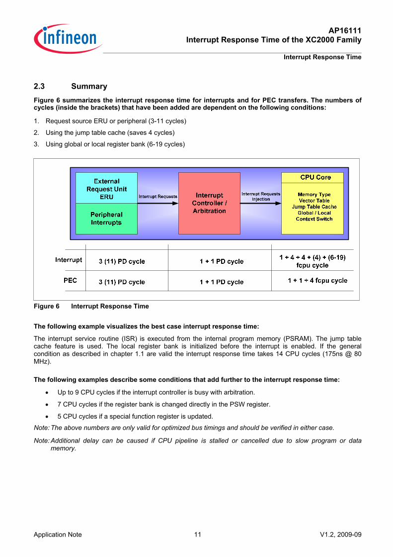
2.3 Summary Figure 6 summarizes the interrupt response time for interrupts and for PEC transfers. The numbers of cycles (inside the brackets) that have been added are dependent on the following conditions:
1. Request source ERU or peripheral (3-11 cycles)
2. Using the jump table cache (saves 4 cycles)
3. Using global or local register bank (6-19 cycles)
Figure 6 Interrupt Response Time
The following example visualizes the best case interrupt response time:
The interrupt service routine (ISR) is executed from the internal program memory (PSRAM). The jump table cache feature is used. The local register bank is initialized before the interrupt is enabled. If the general condition as described in chapter 1.1 are valid the interrupt response time takes 14 CPU cycles (175ns @ 80 MHz).
The following examples describe some conditions that add further to the interrupt response time:
• Up to 9 CPU cycles if the interrupt controller is busy with arbitration.
• 7 CPU cycles if the register bank is changed directly in the PSW register.
• 5 CPU cycles if a special function register is updated.
Note: The above numbers are only valid for optimized bus timings and should be verified in either case.
Note: Additional delay can be caused if CPU pipeline is stalled or cancelled due to slow program or data memory.

AP16111 Interrupt Response Time of the XC2000 Family
Configuration of the Interrupt Handler
Application Note 12 V1.2, 2009-09
3 Configuration of the Interrupt Handler
3.1 Potentials to Influence the Interrupt Response Time
The XC2000 architecture offers a couple of dedicated registers to configure the interrupt handler. The configuration can be divided in two groups: • Interrupt jump table cache. • Fast bank switching.
3.1.1 Jump Table Cache (Fast Interrupt)
The interrupt servicing time can be reduced by the interrupt jump table cache. This feature eliminates the explicit branch to the ISR by directly providing the CPU with the service routine location.
The two pointers are each stored in a pair of interrupt jump table cache registers, which store an 8 bit pointer segment and a 16 bit offset along with the priority level (priority level 12-15). These features can be selected for two interrupt sources.
Figure 7 Jump Table Cache Registers

AP16111 Interrupt Response Time of the XC2000 Family
Configuration of the Interrupt Handler
Application Note 13 V1.2, 2009-09
3.1.2 Fast Bank Switching The XC2000 architecture allows switching the selected physical register bank. By updating the bitfield BANK in register PSW the active register bank is switched. In case of an interrupt service, the bank switch is automatically executed by updating bitfield BANK from BNKSELx in the interrupt controller. For interrupt priority levels 12…15 the target register bank can be pre-selected. The registers BNKSELx provides a 2-bit field for each possible arbitration priority level. The respective bitfield is then copied to bitfield BANK in register PSW to select the register bank, as soon as the respective interrupt request is accepted. After a switch to a local register bank, the new bank is immediately available.
Figure 8 Registers BNKSEL0-3 for Interrupt Priority Level 12-15

AP16111 Interrupt Response Time of the XC2000 Family
Configuration of the Interrupt Handler
Application Note 14 V1.2, 2009-09
3.2 C-Compiler and Configuration of the Interrupt Handler Both Keil and Tasking Compilers support the enhanced interrupt handling of the XC2000 architecture. The following hints may be useful to illustrate how the user may to influence the interrupt response time.
3.2.1 Keil The Keil C-Compiler supports the XC2000 architecture and the enhanced interrupt handling. For more detailed information please refer to the Keil C-Compiler manual or C166: Using XC2000 Fast Register Bank Switching.
There are different register bank switching methods available. They can be controlled with different specifiers for 'rbank_id':
Omitting using: The compiler generates code to save (PUSH) and restore (POP) all registers that are used in this function to the system stack. Saving and restoring the register values takes time. However, if you have a very small interrupt function where only a few registers are used, this might be the most effective method.
Any Name: The compiler generates code to save (PUSH) the current context pointer register (CP) and loads it with the address of a dedicated register bank. At the end of the ISR the CP register is restored. The registers R0 to R15 don't need to be saved on the system stack in this case. Specifying a register bank speeds up the execution of an ISR.
_FAST_BANK1_ or _FAST_BANK2_: The compiler generates code to switch to a fast register bank by modifying the BANK field of the program status word (PSW). The registers R0 to R15 don't need to be saved on the system stack in this case.
_FAST_ABANK1_ or _FAST_ABANK2_: The compiler does not generate code to switch to a different register bank or to save the current registers (R0 - R15). The interrupt controller (BNKSELx register) must be initialized to switch to a fast register bank automatically on entering the ISR by the user application.
The following C-Examples illustrate the configuration and the interrupt handling.
General Interrupt using Global Register Bank
void CC1_vInit(void)
{ .......
PSW_IEN = 1; // set global interrupt enable
}
void CC2_viTmr7(void) interrupt CC2_T7INT
{.......
}// End of function CC2_viTmr7

AP16111 Interrupt Response Time of the XC2000 Family
Configuration of the Interrupt Handler
Application Note 15 V1.2, 2009-09
Interrupt Jump Table Cache
An interrupt service routine (ISR) can be defined with "<Name>=CACHED" instead of an interrupt vector number. In this case, no interrupt vector is generated. The application needs to program the interrupt controller registers FINTxCSP and FINTxADDR with the address of the ISR before the interrupt is enabled. The following example shows how to do it:
void CC2_viTmr7(void) interrupt CC2_T7INT =CACHED
{ .......
}// End of function CC2_viTmr7
#define SEG(func) (unsigned int)(((unsigned long)((void (far *)(void))func) >> 16))
#define SOF(func) (unsigned int)(((void (far *) (void))func))
void CC2_vInit(void)
{.......
// Initialize fast interrupt register: EN=1, ILVL=15, GLVL=0, GPX=0
FINT0CSP = SEG(CC2_Tmr7) | 0x8C00;
FINT0ADDR = SOF(CC2_Tmr7);
PSW_IEN = 1; // set global interrupt enable
}
Fast Bank Switching
When using _FAST_BANKx_ or _FAST_ABANKx_ a separate user stack needs to be defined for these ISR's. This is done with UST1SZ and UST2SZ in the START_V2.A66 file. Be sure to define a range that is big enough to hold the local variables of the ISR.
UST1SZ EQU 0x20 ; set User Stack Size to 20H Bytes
UST2SZ EQU 0x20 ; set User Stack Size to 20H Bytes
When _FAST_ABANKx_ is used, the interrupt controller register BNKSELx needs to be initialized before the interrupt is enabled. The following example shows how to do it:
void CC2__viCC2(void) interrupt CC2_T7INT using _FAST_ABANK2_
{......
}
void CC2_vInit(void)
{......
BNKSEL1=0x0300; // BNKSEL1.GPRSEL4=11 -> Local register bank 2
PSW_IEN = 1; // set global interrupt enable
}

AP16111 Interrupt Response Time of the XC2000 Family
Configuration of the Interrupt Handler
Application Note 16 V1.2, 2009-09
Fast Bank Switching + Jump Table Cache:
void CC1_viCC1(void) interrupt CC2_T7INT =CACHED using _FAST_ABANK2_
{......
}
void CC1_vInit(void)
{......
BNKSEL1=0x0300; // BNKSEL1.GPRSEL4=11 -> Local register bank 2
PSW_IEN = 1; // set global interrupt enable
}
3.2.2 Tasking
Both Compiler technologies from Tasking C-Compiler support the XC2000 architecture and the enhanced interrupt handling. Included are some useful extensions to force fast register bank switching, cached interrupts, etc. For more detailed information please refer to the Tasking C-Compiler manual.
3.2.2.1 Tasking C166 Toolset _stacksize (num) // specifies the userstack adjustment in byte
_localbank (num) // local register bank switching (0,1,2,-1,-2) 0 = Global register bank
-1 / -2 = local register bank1/2, BNKSEL0 should be used
1 / 2 = local register bank1/2, PSW is set in the ISR ( not recommended !)
_cached // bypasses the interrupt vector table
#pragma noframe // omit the whole interrupt frame, allows you to make your own interrupt frame. Should be used carefully!
#pragma autosavemac // Save MAC registers only when needed
General Interrupt using Global Register Bank
The timer T7 overflow interrupt is enabled. If a timer T7 overflow occurs, the service routine switches the context of the global register bank to get a new set of GPRs.
interrupt (CC2_T7INT) void CC2_viTmr7(void)
{ ......
}

AP16111 Interrupt Response Time of the XC2000 Family
Configuration of the Interrupt Handler
Application Note 17 V1.2, 2009-09
Interrupt Jump Table Cache
The timer T7 overflow interrupt is enabled. If a timer T7 overflow occurs, the service routine switches the context of the global register bank to get a new set of GPRs. Instead of using the vector table the CPU directly takes the addresses of the service routine.
interrupt (CC2_T7INT) _cached void CC2_viTmr7(void)
{......
}
void CC2_vInit(void)
extern interrupt (CC2_T7INT) _cached void CC2_viTmr7(void);
{......
FINT0CSP = 0x8000 | (((unsigned long)&(CC2_viTmr7))>>16);
FINT0ADDR = (unsigned int)&(CC2_viTmr7);
PSW_IEN = 1; // set global interrupt enable
}
Fast Bank Switching + Jump Table Cache
The timer T7 overflow interrupt is enabled. If a timer T7 overflow occurs, the service routine switches automatically to the local register bank 1. Instead of using the vector table the CPU directly takes the addresses of the service routine.
interrupt (CC2_T7INT) _localbank(-1) _stacksize(50) _cached void CC2_viTmr7(void)
{ ......
}
void CC2_vInit(void)
extern interrupt (CC2_T7INT) _localbank(-1) _stacksize(+50) void CC2_viTmr7(void);
{......
FINT0CSP = 0x8000 | (((unsigned long)&(CC2_viTmr7))>>16);
FINT0ADDR = (unsigned int)&(CC2_viTmr7);
BNKSEL0 = 0x0002; // Set local register bank 1 for Interr.level 12, group 0
PSW_IEN = 1; // set global interrupt enable
}

AP16111 Interrupt Response Time of the XC2000 Family
Configuration of the Interrupt Handler
Application Note 18 V1.2, 2009-09
Fast Bank Switching + Jump Table Cache (advanced)
The timer T7 overflow interrupt is enabled. If a timer T7 overflow occurs, the service routine switches automatically to the local register bank 1. Instead of using the vector table the CPU directly takes the addresses of the service routine.
interrupt (CC2_T7INT) _localbank(-1) _stacksize(50) _cached void CC2_viTmr7(void)
#pragma noframe // omit the whole interrupt frame
{......
}
void CC2_vInit(void)
extern interrupt (CC2_T7INT) _localbank(-1) _stacksize(+50) void CC2_viTmr7(void);
{......
FINT0CSP = 0x8000 | (((unsigned long)&(CC2_viTmr7))>>16);
FINT0ADDR = (unsigned int)&(CC2_viTmr7);
BNKSEL0 = 0x0002; // Set local register bank 1 for Interr.level 12, // group 0
PSW_IEN = 1; // set global interrupt enable
}
This is the fastest way to process an interrupt call because the extension #pragma noframe omits the whole interrupt frame. Using this extension makes the user responsible for storing all the controller specific registers, like data pointers, multiply registers, etc.
Instead of using the extension #pragma noframe a more efficient way is to use the extension #pragma nosavemac. This extension forces the compiler do not save the MAC registers. It reduces the interrupt frame by 2 x 12 instructions.

AP16111 Interrupt Response Time of the XC2000 Family
Configuration of the Interrupt Handler
Application Note 19 V1.2, 2009-09
3.2.2.2 Tasking VX C166 Toolset
__interrupt() // declare a function as an interrupt service routine
For example:
void __interrupt (CC2 T7INT) CC2_viTmr7(void)
{
..
}
__frame() // specify which registers and SFRs must be saved
For example:
void __interrupt (CC2 T7INT) __frame(MDL, MDH) CC2_viTmr7(void)
{
..
}
__registerbank // assign a new registerbank to an interrupt function
For example:
void __interrupt (CC2 T7INT) __registerbank(Bank1) CC2_viTmr7(void)
{
..
}
The string Bank1 specifies the name of the global register bank to be used.
For example:
void __interrupt (CC2 T7INT) __registerbank(-1) CC2_viTmr7(void)
{
..
}
The numbers (0,1,2,-1-2) specifies the numbers of local register banks. The number 0 stands for global register bank. With the negative numbers, the compiler assumes that local register banks are used. With positive numbers, the compiler generates code to select the local register banks, it increase the interrupt response time (not recommended).

AP16111 Interrupt Response Time of the XC2000 Family
Configuration of the Interrupt Handler
Application Note 20 V1.2, 2009-09
General Interrupt using Global Register Bank
The timer T7 overflow interrupt is enabled. If a timer T7 overflow occurs, the service routine switches the context of the global register bank to get a new set of GPRs.
void __interrupt (CC2_T7INT) void CC2_viTmr7(void)
{ ......
}
Fast Bank Switching + Jump Table Cache
The timer T7 overflow interrupt is enabled. If a timer T7 overflow occurs, the service routine switches automatically to the local register bank 1. Instead of using the vector table the CPU directly takes the addresses of the service routine. In the interrupt frame only the MAC registers MDL and MDH are saved.
void __interrupt (CC2 T7INT) __frame(MDL, MDH) __registerbank(-1) CC2_viTmr7(void)
{ ......
}
void CC2_vInit(void)
extern void __interrupt (CC2 T7INT) __frame(MDL, MDH)
__registerbank(-1) CC2_viTmr7(void);
{......
FINT0CSP = 0x8000 | (((unsigned long)&(CC2_viTmr7))>>16);
FINT0ADDR = (unsigned int)&(CC2_viTmr7);
BNKSEL0 = 0x0002; // Set local register bank 1 for Interr.level 12, group 0
PSW_IEN = 1; // set global interrupt enable
}

AP16111 Interrupt Response Time of the XC2000 Family
Conclusion
Application Note 21 V1.2, 2009-09
4 Conclusion The architecture of the XC2000 supports several powerful mechanisms for fast and flexible response to service requests from various sources. For optimized code and dataflow the customer has to analyze the real time requirements of their application. The interrupt architecture of the XC2000 together with the different tool chains perfectly supports these requirements.

w w w . i n f i n e o n . c o m
Published by Infineon Technologies AG