Anupam Term Paper
8
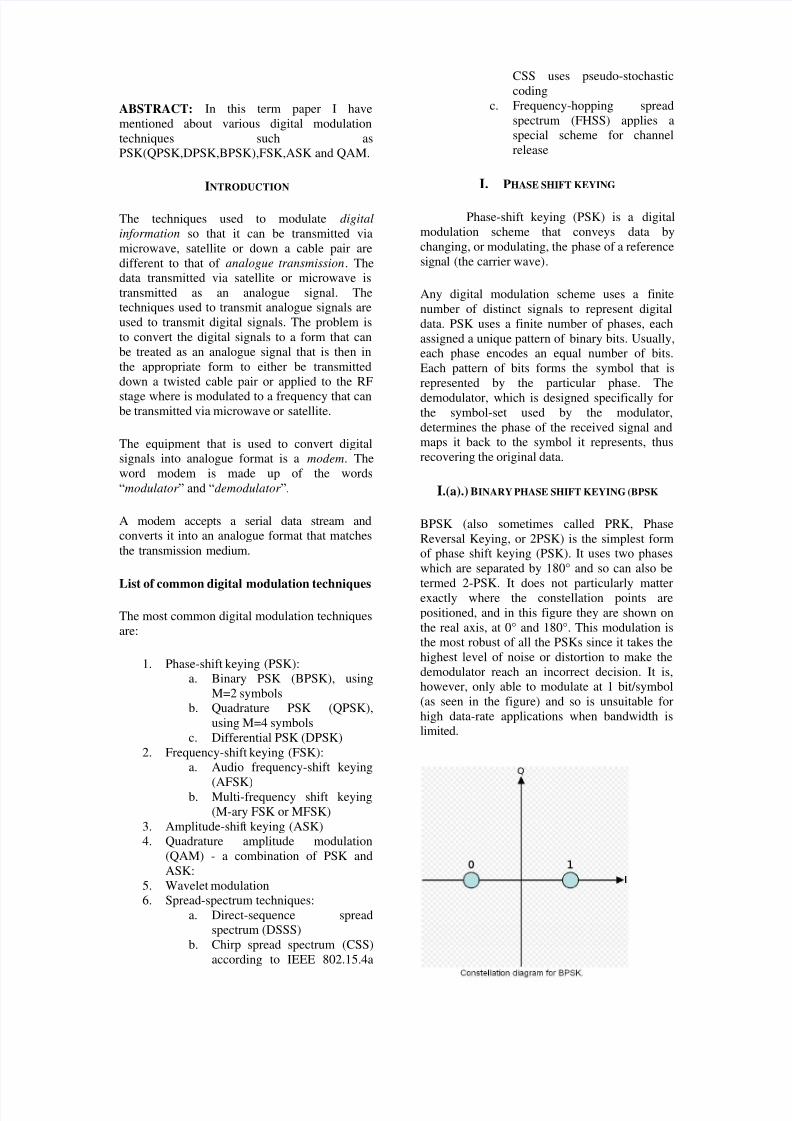
ABSTRACT: In this term paper I have mentioned about various digital modulation techniques such as PSK(QPSK,DPSK,BPSK),FSK,ASK and QAM. INTRODUCTION The techniques used to modulate digital information so that it can be transmitted via microwave, satellite or down a cable pair are different to that of analogue transmission. The data transmitted via satellite or microwave is transmitted as an analogue signal. The techniques used to transmit analogue signals are used to transmit digital signals. The problem is to convert the digital signals to a form that can be treated as an analogue signal that is then in the appropriate form to either be transmitted down a twisted cable pair or applied to the RF stage where is modulated to a frequency that can be transmitted via microwave or satellite. The equipment that is used to convert digital signals into analogue format is a modem. The word modem is made up of the words “modulator ” and “demodulator ”. A modem accepts a serial data stream and converts it into an analogue format that matches the transmission medium. List of common digital modulation techniques The most common digital modulation techniques are: 1. Phase-shift keying (PSK): a. Binary PSK (BPSK), using M=2 symbols b. Quadrature PSK (QPSK), using M=4 symbols c. Differential PSK (DPSK) 2. Frequency-shift keying (FSK): a. Audio frequency-shift keying (AFSK) b. Multi-frequency shift keying (M-ary FSK or MFSK) 3. Amplitude-shif t keying (ASK) 4. Quadrature amplitude modulation (QAM) - a combination of PSK and ASK: 5. Wavelet modulation 6. Spread-spectrum techniques: a. Direct-sequence spread spectrum (DSSS) b. Chirp spread spectrum (CSS) according to IEEE 802.15.4a CSS uses pseudo-stochastic coding c. Frequency-hopping spread spectrum (FHSS) applies a special scheme for channel release I. PHASE SHIFT KEYING Phase-shift keying (PSK) is a digital modulation scheme that conveys data by changing, or modulating, the phase of a reference signal (the carrier wave). Any digital modulation scheme uses a finite number of distinct signals to represent digital data. PSK uses a finite number of phases, each assigned a unique pattern of binary bits. Usually, each phase encodes an equal number of bits. Each pattern of bits forms the symbol that is represented by the particular phase. The demodulator, which is designed specifically for the symbol-set used by the modulator, determines the phase of the received signal and maps it back to the symbol it represents, thus recovering the original data. I.(a).) BINARY PHASE SHIFT KEYING (BPSK BPSK (also sometimes called PRK, Phase Reversal Keying, or 2PSK) is the simplest form of phase shift keying (PSK). It uses two phases which are separated by 180° and so can also be termed 2-PSK. It does not particularly matter exactly where the constellation points are positioned, and in this figure they are shown on the real axis, at 0° and 180°. This modulation is the most robust of all the PSKs since it takes the highest level of noise or distortion to make the demodulator reach an incorrect decision. It is, however, only able to modulate at 1 bit/symbol (as seen in the figure) and so is unsuitable for high data-rate applications when bandwidth is limited.
-
Upload
abhishek-mishra -
Category
Documents
-
view
226 -
download
0
Transcript of Anupam Term Paper
8/3/2019 Anupam Term Paper
http://slidepdf.com/reader/full/anupam-term-paper 1/8
ABSTRACT: In this term paper I have
mentioned about various digital modulation
techniques such as
PSK(QPSK,DPSK,BPSK),FSK,ASK and QAM.
INTRODUCTION
The techniques used to modulate digital
information so that it can be transmitted via
microwave, satellite or down a cable pair are
different to that of analogue transmission. The
data transmitted via satellite or microwave is
transmitted as an analogue signal. The
techniques used to transmit analogue signals are
used to transmit digital signals. The problem is
to convert the digital signals to a form that can
be treated as an analogue signal that is then in
the appropriate form to either be transmitted
down a twisted cable pair or applied to the RF
stage where is modulated to a frequency that canbe transmitted via microwave or satellite.
The equipment that is used to convert digital
signals into analogue format is a modem. The
word modem is made up of the words
“modulator ” and “demodulator ”.
A modem accepts a serial data stream and
converts it into an analogue format that matches
the transmission medium.
List of common digital modulation techniques
The most common digital modulation techniques
are:
1. Phase-shift keying (PSK):
a. Binary PSK (BPSK), using
M=2 symbols
b. Quadrature PSK (QPSK),
using M=4 symbols
c. Differential PSK (DPSK)
2. Frequency-shift keying (FSK):
a. Audio frequency-shift keying
(AFSK)b. Multi-frequency shift keying
(M-ary FSK or MFSK)
3. Amplitude-shift keying (ASK)
4. Quadrature amplitude modulation
(QAM) - a combination of PSK and
ASK:
5. Wavelet modulation
6. Spread-spectrum techniques:
a. Direct-sequence spread
spectrum (DSSS)
b. Chirp spread spectrum (CSS)
according to IEEE 802.15.4a
CSS uses pseudo-stochastic
coding
c. Frequency-hopping spread
spectrum (FHSS) applies a
special scheme for channel
release
I. PHASE SHIFT KEYING
Phase-shift keying (PSK) is a digital
modulation scheme that conveys data by
changing, or modulating, the phase of a reference
signal (the carrier wave).
Any digital modulation scheme uses a finite
number of distinct signals to represent digital
data. PSK uses a finite number of phases, each
assigned a unique pattern of binary bits. Usually,
each phase encodes an equal number of bits.
Each pattern of bits forms the symbol that is
represented by the particular phase. The
demodulator, which is designed specifically forthe symbol-set used by the modulator,
determines the phase of the received signal and
maps it back to the symbol it represents, thus
recovering the original data.
I.(a).) BINARY PHASE SHIFT KEYING (BPSK
BPSK (also sometimes called PRK, Phase
Reversal Keying, or 2PSK) is the simplest form
of phase shift keying (PSK). It uses two phases
which are separated by 180° and so can also be
termed 2-PSK. It does not particularly matter
exactly where the constellation points are
positioned, and in this figure they are shown on
the real axis, at 0° and 180°. This modulation is
the most robust of all the PSKs since it takes the
highest level of noise or distortion to make the
demodulator reach an incorrect decision. It is,
however, only able to modulate at 1 bit/symbol
(as seen in the figure) and so is unsuitable for
high data-rate applications when bandwidth is
limited.

8/3/2019 Anupam Term Paper
http://slidepdf.com/reader/full/anupam-term-paper 2/8
FIG.1. CONSTELLATION DIAGRAM FOR BPSK
IMPLEMENTATION:
Binary data is often conveyed with the following
signals:
for binary "0"
for binary "1"
where f c is the frequency of the carrier-wave.
Hence, the signal-space can be represented by
the single basis functionwhere 1 is represented by and 0 is represented by
. This assignment is, of course, arbitrary.
The use of this basis function is shown at the end
of the next section in a signal timing diagram.
The topmost signal is a BPSK-modulated cosine
wave that the BPSK modulator would produce.
The bit-stream that causes this output is shown
above the signal (the other parts of this figure are
relevant only to QPSK).
FIG.2. DIAGRAM FOR BPSK
BIT ERROR RATE:
The bit error rate (BER) of BPSK in AWGN can
be calculated as[5]
:
orSince there is only one bit per symbol, this is
also the symbol error rate.
I.(b).QUADRATURE PHASE SHIFT KEYING
(QPSK)
Constellation diagram for QPSK with Gray
coding. Each adjacent symbol only differs by
one bit.
Sometimes known as quaternary or quadriphase
PSK, 4-PSK, or 4-QAM[6]
, QPSK uses four
points on the constellation diagram, equispaced
around a circle. With four phases, QPSK can
encode two bits per symbol. Analysis shows that
this may be used either to double the data rate
compared to a BPSK system while maintaining
the bandwidth of the signal or to maintain the
data-rate of BPSK but halve the bandwidth
needed.
As with BPSK, there are phase ambiguity
problems at the receiver and differentially
encoded QPSK is used more often in practice.
FIG.3. CONSTELLATION DIAGRAM FOR QPSK
IMPLEMENTATION:
The implementation of QPSK is more general
than that of BPSK and also indicates the
implementation of higher-order PSK. Writing the
symbols in the constellation diagram in terms of
the sine and cosine waves used to transmit them:
This yields the four phases π/4, 3π/4, 5π/4 and7π/4 as needed.
This results in a two-dimensional signal space
with unit basis functions
The first basis function is used as the in-phase
component of the signal and the second as the
quadrature component of the signal.
Hence, the signal constellation consists of the
signal-space 4 points
The factors of 1/2 indicate that the total power is
split equally between the two carriers.
Comparing these basis functions with that for
BPSK shows clearly how QPSK can be viewed
as two independent BPSK signals. Note that the
signal-space points for BPSK do not need to splitthe symbol (bit) energy over the two carriers in
the scheme shown in the BPSK constellation
diagram.
QPSK systems can be implemented in a number
of ways. An illustration of the major components
of the transmitter and receiver structure are
shown below.

8/3/2019 Anupam Term Paper
http://slidepdf.com/reader/full/anupam-term-paper 3/8
FIG.4. TRANSMITTER AND RECIEVER DIAGRAM
Conceptual transmitter structure for QPSK. The
binary data stream is split into the in-phase and
quadrature-phase components. These are then
separately modulated onto two orthogonal basis
functions. In this implementation, two sinusoids
are used. Afterwards, the two signals are
superimposed, and the resulting signal is the
QPSK signal. Note the use of polar non-return-
to-zero encoding. These encoders can be placed
before for binary data source, but have beenplaced after to illustrate the conceptual
difference between digital and analog signals
involved with digital modulation.
Receiver structure for QPSK. The matched filters
can be replaced with correlators. Each detection
device uses a reference threshold value to
determine whether a 1 or 0 is detected.
Bit error rate
Although QPSK can be viewed as a quaternarymodulation, it is easier to see it as two
independently modulated quadrature carriers.
With this interpretation, the even (or odd) bits
are used to modulate the in-phase component of
the carrier, while the odd (or even) bits are used
to modulate the quadrature-phase component of
the carrier. BPSK is used on both carriers and
they can be independently demodulated.
As a result, the probability of bit-error for QPSK
is the same as for BPSK:
However, in order to achieve the same bit-error
probability as BPSK, QPSK uses twice the
power (since two bits are transmitted
simultaneously).
The symbol error rate is given by:
If the signal-to-noise ratio is high (as is
necessary for practical QPSK systems) the
probability of symbol error may be
approximated:
QPSK SIGNAL IN THE TIME DOMAIN:
The modulated signal is shown below for a shortsegment of a random binary data-stream. The
two carrier waves are a cosine wave and a sine
wave, as indicated by the signal-space analysis
above. Here, the odd-numbered bits have been
assigned to the in-phase component and the
even-numbered bits to the quadrature component
(taking the first bit as number 1). The total signal
— the sum of the two components — is shown at
the bottom. Jumps in phase can be seen as the
PSK changes the phase on each component at the
start of each bit-period. The topmost waveform
alone matches the description given for BPSK
above.
FIG.5. WAVEFORM FOR QPSK
The binary data that is conveyed by this
waveform is: 1 1 0 0 0 1 1 0.
The odd bits, highlighted here,
contribute to the in-phase component: 1
1 0 0 0 1 1 0
The even bits, highlighted here,contribute to the quadrature-phase
component: 1 1 0 0 0 1 1 0
I.C.DIFFERENTIAL PHASE-SHIFT KEYING (DPSK)
Differential phase shift keying (DPSK) is a
common form of phase modulation that conveys
data by changing the phase of the carrier wave.
As mentioned for BPSK and QPSK there is an
ambiguity of phase if the constellation is rotated
by some effect in the communications channel
through which the signal passes. This problem
8/3/2019 Anupam Term Paper
http://slidepdf.com/reader/full/anupam-term-paper 4/8
can be overcome by using the data to change
rather than set the phase.
For example, in differentially-encoded BPSK a
binary '1' may be transmitted by adding 180° to
the current phase and a binary '0' by adding 0° to
the current phase. In differentially-encoded
QPSK, the phase-shifts are 0°, 90°, 180°, -90°
corresponding to data '00', '01', '11', '10'. This
kind of encoding may be demodulated in the
same way as for non-differential PSK but thephase ambiguities can be ignored. Thus, each
received symbol is demodulated to one of the
M points in the constellation and a
comparator then computes the difference in
phase between this received signal and the
preceding one. The difference encodes the data
as described above.
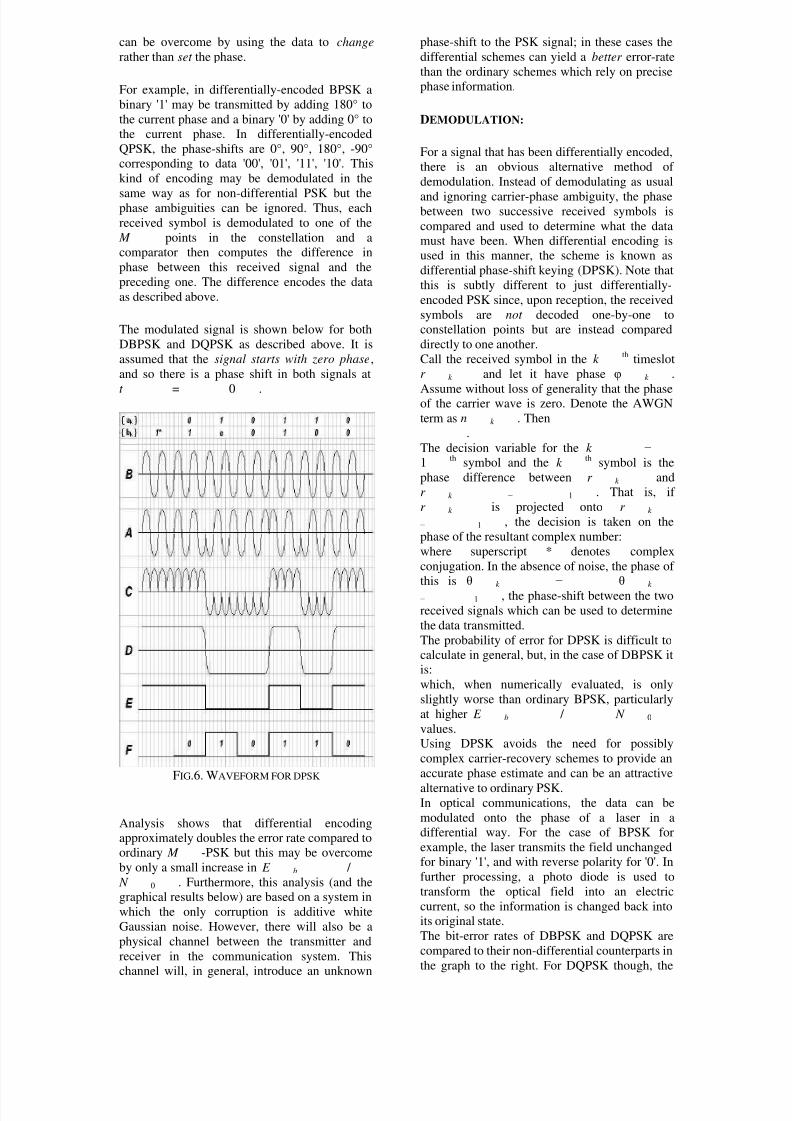
The modulated signal is shown below for both
DBPSK and DQPSK as described above. It is
assumed that the signal starts with zero phase,
and so there is a phase shift in both signals at
t = 0 .
FIG.6. WAVEFORM FOR DPSK
Analysis shows that differential encoding
approximately doubles the error rate compared to
ordinary M -PSK but this may be overcome
by only a small increase in E b /
N 0 . Furthermore, this analysis (and the
graphical results below) are based on a system in
which the only corruption is additive white
Gaussian noise. However, there will also be a
physical channel between the transmitter and
receiver in the communication system. This
channel will, in general, introduce an unknown
phase-shift to the PSK signal; in these cases the
differential schemes can yield a better error-rate
than the ordinary schemes which rely on precise
phase information.
DEMODULATION:
For a signal that has been differentially encoded,
there is an obvious alternative method of
demodulation. Instead of demodulating as usual
and ignoring carrier-phase ambiguity, the phasebetween two successive received symbols is
compared and used to determine what the data
must have been. When differential encoding is
used in this manner, the scheme is known as
differential phase-shift keying (DPSK). Note that
this is subtly different to just differentially-
encoded PSK since, upon reception, the received
symbols are not decoded one-by-one to
constellation points but are instead compared
directly to one another.
Call the received symbol in the k th
timeslot
r k and let it have phase φ k .
Assume without loss of generality that the phaseof the carrier wave is zero. Denote the AWGN
term as n k . Then
.
The decision variable for the k −
1th
symbol and the k th
symbol is the
phase difference between r k and
r k − 1 . That is, if
r k is projected onto r k
− 1 , the decision is taken on the
phase of the resultant complex number:
where superscript * denotes complex
conjugation. In the absence of noise, the phase of
this is θ k − θ k
− 1 , the phase-shift between the two
received signals which can be used to determine
the data transmitted.
The probability of error for DPSK is difficult to
calculate in general, but, in the case of DBPSK it
is:
which, when numerically evaluated, is only
slightly worse than ordinary BPSK, particularly
at higher E b / N 0
values.
Using DPSK avoids the need for possibly
complex carrier-recovery schemes to provide an
accurate phase estimate and can be an attractive
alternative to ordinary PSK.In optical communications, the data can be
modulated onto the phase of a laser in a
differential way. For the case of BPSK for
example, the laser transmits the field unchanged
for binary '1', and with reverse polarity for '0'. In
further processing, a photo diode is used to
transform the optical field into an electric
current, so the information is changed back into
its original state.
The bit-error rates of DBPSK and DQPSK are
compared to their non-differential counterparts in
the graph to the right. For DQPSK though, the

8/3/2019 Anupam Term Paper
http://slidepdf.com/reader/full/anupam-term-paper 5/8
loss in performance compared to ordinary QPSK
is larger and the system designer must balance
this against the reduction in complexity.
II.FREQUENCY SHIFT KEYING
Frequency-shift keying (FSK) is a frequency
modulation scheme in which digital information
is transmitted through discrete frequency
changes of a carrier wave. The simplest FSK is
binary FSK (BFSK). BFSK literally implies
using a couple of discrete frequencies to transmitbinary (0s and 1s) information. With this
scheme, the "1" is called the mark frequency and
the "0" is called the space frequency.
FIG.7. WAVEFORM OF BFSK SIGNAL
FIG.8. PSD OF BFSK SIGNAL
II.b.MINIMUM SHIFT KEYING
Minimum frequency-shift keying or minimum-
shift keying (MSK) is a particularly spectrally
efficient form of coherent FSK. In MSK the
difference between the higher and lower
frequency is identical to half the bit rate.
Consequently, the waveforms used to represent a
0 and a 1 bit differ by exactly half a carrier
period. This is the smallest FSK modulation
index that can be chosen such that the
waveforms for 0 and 1 are orthogonal. A variant
of MSK called GMSK is used in the GSMmobile phone standard.
FSK is commonly used in Caller ID and remote
metering applications: see FSK standards for use
in Caller ID and remote metering for more
details.
II.c.AUDIO SHIFT KEYING
Audio frequency-shift keying (AFSK) is a
modulation technique by which digital data is
represented by changes in the frequency (pitch)
of an audio tone, yielding an encoded signal
suitable for transmission via radio or telephone. Normally, the transmitted audio alternates
between two tones: one, the "mark", represents a
binary one; the other, the "space", represents a
binary zero.
AFSK differs from regular frequency-shift
keying in performing the modulation at
baseband frequencies. In radio applications, the
AFSK-modulated signal normally is being used
to modulate an RF carrier (using a conventional
technique, such as AM or FM) for transmission.
AFSK is not always used for high-speed data
communications, since it is far less efficient in
both power and bandwidth than most other
modulation modes. In addition to its simplicity,
however, AFSK has the advantage that encoded
signals will pass through AC-coupled links,
including most equipment originally designed to
carry music or speech.
III. AMPLITUDE SHIFT KEYING
Amplitude-shift keying (ASK) is a form of
modulation that represents digital data as
variations in the amplitude of a carrier wave.
The amplitude of an analog carrier signal varies
in accordance with the bit stream (modulating
signal), keeping frequency and phase constant.
The level of amplitude can be used to represent
binary logic 0s and 1s. We can think of a carrier
signal as an ON or OFF switch. In the modulated
signal, logic 0 is represented by the absence of a
carrier, thus giving OFF/ON keying operation
and hence the name given.

8/3/2019 Anupam Term Paper
http://slidepdf.com/reader/full/anupam-term-paper 6/8
Like AM, ASK is also linear and sensitive to
atmospheric noise, distortions, propagation
conditions on different routes in PSTN, etc. Both
ASK modulation and demodulation processes
are relatively inexpensive. The ASK technique is
also commonly used to transmit digital data over
optical fiber. For LED transmitters, binary 1 is
represented by a short pulse of light and binary 0
by the absence of light. Laser transmitters
normally have a fixed "bias" current that causes
the device to emit a low light level. This lowlevel represents binary 0, while a higher-
amplitude lightwave represents binary 1.
ENCODING:
The simplest and most common form of ASK
operates as a switch, using the presence of a
carrier wave to indicate a binary one and its
absence to indicate a binary zero. This type of
modulation is called on-off keying, and is used
at radio frequencies to transmit Morse code
(referred to as continuous wave operation).
More sophisticated encoding schemes have beendeveloped which represent data in groups using
additional amplitude levels. For instance, a four-
level encoding scheme can represent two bits
with each shift in amplitude; an eight-level
scheme can represent three bits; and so on. These
forms of amplitude-shift keying require a high
signal-to-noise ratio for their recovery, as by
their nature much of the signal is transmitted at
reduced power.
Here is a diagram showing the ideal model for a
transmission system using an ASK modulation
FIG.9. TRANSMISSION AND RECIEVAL OF ASK SIGNAL
It can be divided into three blocks. The first one
represents the transmitter, the second one is a
linear model of the effects of the channel, the
third one shows the structure of the receiver. The
following notation is used:
ht (t) is the carrier signal for the
transmission
hc(t) is the impulse response of the
channel
n(t) is the noise introduced by the
channel
hr (t) is the filter at the receiver
L is the number of levels that are used
for transmission
T s is the time between the generation of
two symbols
Different symbols are represented with different
voltages. If the maximum allowed value for the
voltage is A, then all the possible values are in
the range [-A,A] and they are given by:
the difference between one voltage and the other
is:
Considering the picture, the symbols v[n] are
generated randomly by the source S, then the
impulse generator creates impulses with an area
of v[n]. These impulses are sent to the filter ht to
be sent through the channel. In other words, foreach symbol a different carrier wave is sent with
the relative amplitude.
Out of the transmitter, the signal s(t) can be
expressed in the form:
In the receiver, after the filtering through hr (t)
the signal is:
where we use the notation:
n r ( t ) =
n ( t ) *
h r ( t )
g ( t ) =
h t ( t ) *
h c ( t ) *
h r ( t )where * indicates the convolution between two
signals. After the A/D conversion the signal z[k]
can be expressed in the form:
In this relationship, the second term represents
the symbol to be extracted. The others are
unwanted: the first one is the effect of noise, the
second one is due to the intersymbol
interference.
If the filters are chosen so that g(t) will satisfy
the Nyquist ISI criterion, then there will be no
intersymbol interference and the value of the
sum will be zero, so:
z [ k ] =n r [ k ] +
v [ k ] g [ 0
]
the transmission will be affected only by noise.
PROBABILITY OF ERROR:
The probability density function to make an error
after a certain symbol has been sent can be
modelled by a Gaussian function; the mean value
will be the relative sent value, and its variance
will be given by:where Φ N ( f ) is the spectral
density of the noise within the band and H r (f) is
the continuous Fourier transform of the impulse
response of the filter hr (f).
The possibility to make an error is given by:
where is the conditional probability of making an
error after a symbol vi has been sent and is the
probability of sending a symbol v0.
If the probability of sending any symbol is the
same, then:
If we represent all the probability density
functions on the same plot against the possible

8/3/2019 Anupam Term Paper
http://slidepdf.com/reader/full/anupam-term-paper 7/8
value of the voltage to be transmitted, we get a
picture like this (the particular case of L=4 is
shown):
FIG.10. BIT ERROR DIAGRAM
The possibility of making an error after a single
symbol has been sent is the area of the Gaussian
function falling under the other ones. It is shown
in cyan just for one of them. If we call P+
the
area under one side of the Gaussian, the sum of
all the areas will be: 2 L P +
− 2 P +
. The total
probability of making an error can be expressed
in the form:
We have now to calculate the value of P+. In
order to do that, we can move the origin of the
reference wherever we want: the area below the
function will not change. We are in a situation
like the one shown in the following picture:
FIG.11.
it does not matter which Gaussian function we
are considering, the area we want to calculate
will be the same. The value we are looking for
will be given by the following integral:
where erfc() is the complementary error function.
Putting all these results together, the probability
to make an error is:
from this formula we can easily understand that
the probability to make an error decreases if the
maximum amplitude of the transmitted signal or
the amplification of the system becomes greater;
on the other hand, it increases if the number of
levels or the power of noise becomes greater.
IV.QUADRATURE AMPLITUDE MODULATION
Quadrature amplitude modulation (QAM) is both
an analog and a digital modulation scheme. It
conveys two analog message signals, or two
digital bit streams, by changing (modulating) the
amplitudes of two carrier waves, using the
amplitude-shift keying (ASK) digital modulation
scheme or amplitude modulation (AM) analog
modulation scheme. These two waves, usually
sinusoids, are out of phase with each other by90° and are thus called quadrature carriers or
quadrature components — hence the name of the
scheme. The modulated waves are summed, and
the resulting waveform is a combination of both
phase-shift keying (PSK) and amplitude-shift
keying, or in the analog case of phase
modulation (PM) and amplitude modulation. In
the digital QAM case, a finite number of at least
two phases, and at least two amplitudes are used.
PSK modulators are often designed using the
QAM principle, but are not considered as QAM
since the amplitude of the modulated carrier
signal is constant.
IV.a.DIGITAL QAM
Like all modulation schemes, QAM conveys
data by changing some aspect of a carrier signal,
or the carrier wave, (usually a sinusoid) in
response to a data signal. In the case of QAM,
the amplitude of two waves, 90 degrees out-of-
phase with each other (in quadrature) are
changed (modulated or keyed ) to represent the
data signal. Amplitude modulating two carriers
in quadrature can be equivalently viewed as both
amplitude modulating and phase modulating asingle carrier.
Phase modulation (analog PM) and phase-shift
keying (digital PSK) can be regarded as a special
case of QAM, where the magnitude of the
modulating signal is a constant, with only the
phase varying. This can also be extended to
frequency modulation (FM) and frequency-shift
keying (FSK), for these can be regarded as a
special case of phase modulation.
IV.b. ANALOG QAM

8/3/2019 Anupam Term Paper
http://slidepdf.com/reader/full/anupam-term-paper 8/8
When transmitting two signals by modulating
them with QAM, the transmitted signal will be
of the form:
,
where I ( t ) and
Q ( t ) are the modulating signals
and f 0 is the carrier frequency.
At the receiver, these two modulating signals can
be demodulated using a coherent demodulator.
Such a receiver multiplies the received signal
separately with both a cosine and sine signal to
produce the received estimates of
I ( t ) and Q ( t )
respectively. Because of the orthogonality
property of the carrier signals, it is possible to
detect the modulating signals independently.
In the ideal case I ( t ) isdemodulated by multiplying the transmitted
signal with a cosine signal:
Using standard trigonometric identities, we can
write it as:
Low-pass filtering r i ( t )
removes the high frequency terms (containing
4 π f 0 t ), leaving only the
I ( t ) term. This filtered signal is
unaffected by Q ( t ) , showing
that the in-phase component can be received
independently of the quadrature component.
Similarly, we may multiply s ( t )
by a sine wave and then low-pass filter to extractQ ( t ) .
The phase of the received signal is assumed to be
known accurately at the receiver. This issue of
carrier synchronization at the receiver must be
handled somehow in QAM systems. The
coherent demodulator needs to be exactly in
phase with the received signal, or otherwise the
modulated signals cannot be independently
received. For example analog television systems
transmit a burst of the transmitting colour
subcarrier after each horizontal synchronization
pulse for reference.
Analog QAM is used in NTSC and PAL
television systems, where the I- and Q-signals
carry the components of chroma (colour)
information. "Compatible QAM" or C-QUAM is
used in AM stereo radio to carry the stereo
difference information.
REFERENCES
http://if.rainydaycommunications.net/pr
ojects/web%20development/MQP%20
Website/digitalmod.htm
books.google.co.in/books?isbn=0470845295
en.wikipedia.org/wiki/Frequency-shift_keying
www.berk.tc/combas/digital_mod.pdf
www.digitalmodulation.net
www.amazon.com › Books › New &Used Textbooks
G.PROAKIS –COMMUNICATION SYSTEM
BP LATHI -MODERN DIGTAL AND
ANALOG COMMUNICATION SYSTEM