Antiphase Tones Across Transmitting Antennas: A Spectrum Sharing Technique for Cognitive CO-STFC...
15
Wireless Pers Commun DOI 10.1007/s11277-014-1866-0 Antiphase Tones Across Transmitting Antennas: A Spectrum Sharing Technique for Cognitive CO-STFC MB-OFDM UWB System Ravinder Kumar · Anshul Tyagi © Springer Science+Business Media New York 2014 Abstract This paper proposes a spectrum sharing technique for coexistence of multiband orthogonal frequency division multiplexing ultra wideband (UWB) system with other primary wireless services. Existing technique like tone nulling do not utilize subcarriers within victim band, hence affects the throughput of the system. The same nulling effect can be produced by applying antiphase tones across transmitting antennas and simultaneously utilizing the victim band to transmit the data. This scheme can be applied without any impact on the current specifications of the system. In this paper complex orthogonal space time frequency code is implemented to achieve diversity in multiple antenna system. UWB receiver processing is described for both victim and unprotected band. A less computationally complex active interference cancellation scheme is also applied to improve notch depth. The proposed scheme is implemented for fixed frequency interleaving operation and discussed for time frequency interleaving with special cases. The proposed scheme is very simple to implement and provide flexibility in terms of notch width and depth. Keywords Cognitive radio · CO-STFC · MIMO · Multiband-OFDM · Ultra widenband 1 Introduction Spectrum is the most valuable resource in wireless systems but is not unlimited. In today’s world we are surrounded by many wireless services so there is a very high probability that two services have to share the same spectrum. The congestion can be seen in ultra wideband (3.1–10.6 GHz) where primary services such as WiMax (3.5 GHz) and IEEE802.11a (5 GHz) has to share the same band with ultra wideband (UWB) systems. In order to coexist with already existing users called as primary users (PU), UWB systems should have the cognitive radio (CR) [1] capability to detect and create a notch on that portion of the spectrum which falls within the PU band. R. Kumar (B ) · A. Tyagi Department of Electronics and Communication Engineering, IIT Roorkee, Roorkee 247667, Uttarakhand, India e-mail: [email protected] 123
Transcript of Antiphase Tones Across Transmitting Antennas: A Spectrum Sharing Technique for Cognitive CO-STFC...
Wireless Pers CommunDOI 10.1007/s11277-014-1866-0
Antiphase Tones Across Transmitting Antennas:A Spectrum Sharing Technique for Cognitive CO-STFCMB-OFDM UWB System
Ravinder Kumar · Anshul Tyagi
© Springer Science+Business Media New York 2014
Abstract This paper proposes a spectrum sharing technique for coexistence of multibandorthogonal frequency division multiplexing ultra wideband (UWB) system with other primarywireless services. Existing technique like tone nulling do not utilize subcarriers within victimband, hence affects the throughput of the system. The same nulling effect can be producedby applying antiphase tones across transmitting antennas and simultaneously utilizing thevictim band to transmit the data. This scheme can be applied without any impact on the currentspecifications of the system. In this paper complex orthogonal space time frequency codeis implemented to achieve diversity in multiple antenna system. UWB receiver processingis described for both victim and unprotected band. A less computationally complex activeinterference cancellation scheme is also applied to improve notch depth. The proposed schemeis implemented for fixed frequency interleaving operation and discussed for time frequencyinterleaving with special cases. The proposed scheme is very simple to implement and provideflexibility in terms of notch width and depth.
Keywords Cognitive radio · CO-STFC · MIMO · Multiband-OFDM · Ultra widenband
1 Introduction
Spectrum is the most valuable resource in wireless systems but is not unlimited. In today’sworld we are surrounded by many wireless services so there is a very high probability thattwo services have to share the same spectrum. The congestion can be seen in ultra wideband(3.1–10.6 GHz) where primary services such as WiMax (3.5 GHz) and IEEE802.11a (5 GHz)has to share the same band with ultra wideband (UWB) systems. In order to coexist withalready existing users called as primary users (PU), UWB systems should have the cognitiveradio (CR) [1] capability to detect and create a notch on that portion of the spectrum whichfalls within the PU band.
R. Kumar (B) · A. TyagiDepartment of Electronics and Communication Engineering, IIT Roorkee,Roorkee 247667, Uttarakhand, Indiae-mail: [email protected]
123
R. Kumar, A. Tyagi
Multiband orthogonal frequency division multiplexing (MB-OFDM) [2] is a recognizedapproach for implementing UWB systems. It promises to deliver very high data rates up to480 Mbps. Data rate is varied using the following techniques: frequency-domain spreading,time-domain spreading and forward error correction coding. The implementation involvesthe use of three types of time-frequency codes: in the first the coded information is interleavedover three bands, referred to as time-frequency interleaving (TFI); second where the codedinformation is interleaved over two bands, referred to as two-band TFI or TFI2; and finallywhere the coded information is transmitted on a single band, referred to as fixed frequencyinterleaving (FFI). MB-OFDM is highly flexible and a good candidate for cognitive radio CR[3]. The easiest way of creating notch is turning off the OFDM tones. It is also specified in stan-dard [2] which allow individual OFDM subcarriers to be nulled with a limit that a device shalltransmit at least 86 useful tones per band. The receiver may or may not require the knowledgeabout the nulled subcarrier. If we assume the throughput and data rate to be fixed then nullingof the suncarrier leads to symbol loss. The error due to nulled tones can be compensated byconvolution coding to some extent but if number of nulling tones is large then bit error isunavoidable without sacrificing the throughput. In this paper we are assuming throughput tobe constant and comparing the schemes on the basis of BER performance of the system.
Tone nulling is the first step in almost all narrowband interference cancellation tech-niques such as active interference cancellation (AIC) [4,5], adaptive symbol transition [6]etc. Assuming that no information about the position of nulled subcarrier is available at thereceiver then the nulling of tones directly leads to symbol loss and hence increases the biterror rate of the system. The proposed scheme can produce a spectral null at primary userand still decode the symbols (within PU band) at the UWB receiver thereby improving theBER performance of the system. Since the notch characteristic of proposed technique isequivalent to tone nulling hence all above mentioned interference cancellation techniquesare also applicable with antiphase tones across transmitting antennas (ATATA) scheme. AICwith reduced computation complexity is implemented in this paper.
The Paper is organized as follows. In Sect. 2, we review space time frequency encoding,decoding and channel estimation for 2 Tx and 1 Rx in MB-OFDM system. In Sect. 3, wepropose a new technique to create notch and describe receiver processing to decode symbolswithin and outside the victim band. In Sect. 4, we apply modified AIC technique to increasenotch depth in the proposed scheme and complexity comparison with the conventional AIC(C-AIC) is discussed. In Sect. 5, we discuss the implementation of the proposed techniquewith more number of antennas and TFI operation. Section 6 briefs us on simulation resultswhile the conclusions are mentioned in Sect. 7.
2 STFC MB-OFDM and Channel Estimation
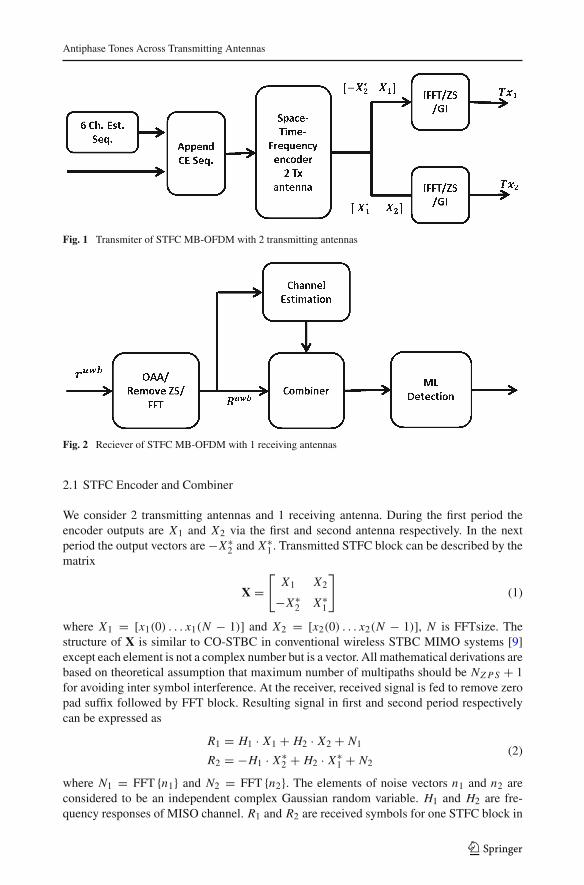
Block diagrams of transmitter and receiver of STFC MB-OFDM system with 2 Tx and 1Rx antennas are shown in Figs. 1 and 2 respectively. For simplicity we have considered twotransmitting antennas and one receiving antenna. Furthermore, this approach is discussedfor more number of transmitting and receiving antennas in Sect. 5. Six periods of channelestimation (CE) sequences are inserted as per standard [2]. Since the training sequence isadded before STFC block so CE sequence within one STFC block will be orthogonal. Usingthis orthogonality we can estimate the channel. MIMO (multiple input multiple output)diversity is achieved using CO-STBC Alamouti code [7] for two transmitting antennas. Theuse of Alamouti code in MB-OFDM UWB system for 2 transmitting antennas is mentionedin [8]. In [9] the author proposed a general framework for STFC MIMO MB-OFDM.
123
Antiphase Tones Across Transmitting Antennas
Fig. 1 Transmiter of STFC MB-OFDM with 2 transmitting antennas
Fig. 2 Reciever of STFC MB-OFDM with 1 receiving antennas
2.1 STFC Encoder and Combiner
We consider 2 transmitting antennas and 1 receiving antenna. During the first period theencoder outputs are X1 and X2 via the first and second antenna respectively. In the nextperiod the output vectors are −X∗
2 and X∗1 . Transmitted STFC block can be described by the
matrix
X =[
X1 X2
−X∗2 X∗
1
](1)
where X1 = [x1(0) . . . x1(N − 1)] and X2 = [x2(0) . . . x2(N − 1)], N is FFTsize. Thestructure of X is similar to CO-STBC in conventional wireless STBC MIMO systems [9]except each element is not a complex number but is a vector. All mathematical derivations arebased on theoretical assumption that maximum number of multipaths should be NZ P S + 1for avoiding inter symbol interference. At the receiver, received signal is fed to remove zeropad suffix followed by FFT block. Resulting signal in first and second period respectivelycan be expressed as
R1 = H1 · X1 + H2 · X2 + N1
R2 = −H1 · X∗2 + H2 · X∗
1 + N2(2)
where N1 = FFT {n1} and N2 = FFT {n2}. The elements of noise vectors n1 and n2 areconsidered to be an independent complex Gaussian random variable. H1 and H2 are fre-quency responses of MISO channel. R1 and R2 are received symbols for one STFC block in
123

R. Kumar, A. Tyagi
two consecutive periods as demonstrated in [9]. X has similar structure as the conventionalOSTBC so the orthogonality of X within one STFC block is preserved in MB-OFDM. Asa result, the simpler and linear decoding algorithm used in conventional wireless OSTBCMIMO systems is also applicable in STFC MB-OFDM UWB systems. Each data point withinan OFDM symbol can be decoded separately by combining the received symbols from (2)using Alamouti combining technique [7] which can be shown as
Y1 = H∗1 · R1 + H2 · R∗
2
Y2 = H∗2 · R1 − H1 · R∗
2
(3)
where H1 and H2 are estimated channels in the frequency domain. Combined signals arethen sent to the maximal likelihood decoder to get the estimated symbols as
X1(i) = decode
(Y1(i)
H1(i)H∗1 (i) + H2(i)H∗
2 (i)
)
X2(i) = decode
(Y2(i)
H1(i)H∗1 (i) + H2(i)H∗
2 (i)
) (4)
2.2 Channel Estimation
Channel estimation plays an important role in ATATA scheme for recovering all symbols atUWB receiver. The channel is estimated using training sequence. The training sequence usedis as per standard [2] which is already in normalized form i.e C × C H = I . One STFC blockconsists of two periods of repeated training sequences. As per expression (2) received signalduring CE sequence can be written as
R1,C E = H1 · C + H2 · C + N1
R2,C E = −H1 · C∗ + H2 · C∗ + N2(5)
where C represents one period of the training sequence. Training sequences within STFCblock are orthogonal hence we can estimate channel using following equations
H1 = C∗ · R1,C E − C · R2,C E
H2 = C∗ · R1,C E + C · R2,C E
(6)
After solving expressions (6) and (5), we get estimated channels as
H1 = H1 + N1′
H2 = H2 + N2′ (7)
where N1′ = C∗ · N1 − C · N2 and N2
′ = C∗ · N1 + C · N2
3 Proposed Scheme
System model displaying various channels is shown in Fig. 3. The main aim is to producea spectral notch at PU receiver and recover the signal at MB-OFDM receiver. All channelsare considered to be frequency selective UWB Channels [10]. H pu
1 , H pu2 , Huwb
1 , Huwb2 are
channel frequency responses of PU link and MB-OFDM link respectively. For theoreticalanalysis we have considered the maximum number of multipaths limited to the length of
123

Antiphase Tones Across Transmitting Antennas
Fig. 3 System model
Fig. 4 Proposed model for ATATA
zero suffix. Discrete fourier transform of MB-OFDM signal signal at PU receiver can beapproximated as
R pu1 (i) = H pu
1 (i)X1(i) + H pu2 (i)X2(i) + N p
1 (i)
R pu2 (i) = −H pu
1 (i)X∗2(i) + H pu
2 (i)X∗1(i) + N p
2 (i)(8)
where R pu1 (i) and R pu
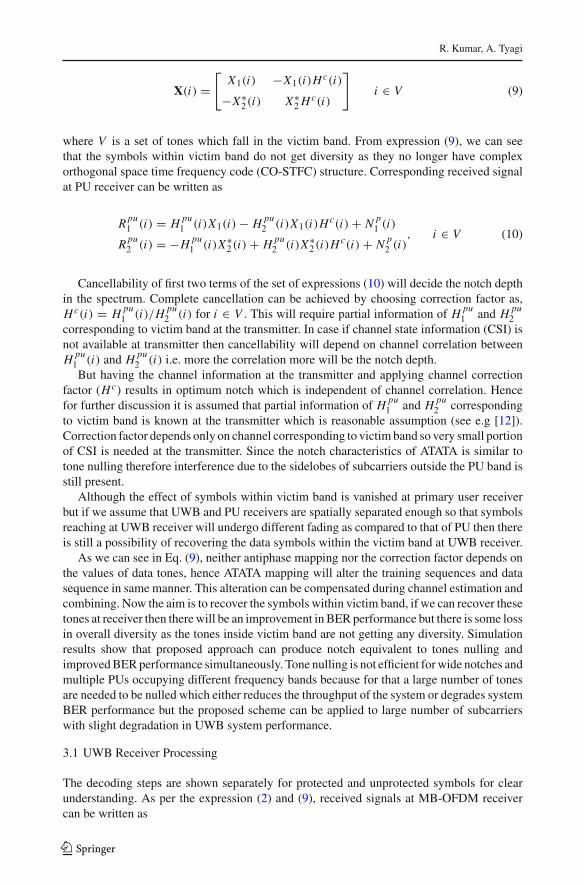
2 (i) denote spectral points in frequency domain for one STFC block intwo consecutive time slots corresponding to i th subcarrier. In order to create a notch at thePU receiver, instead of turning off the tones within interference band we can map ATATAas shown in Fig. 4 so that they try to cancel each other at the receiver of the primary user.In the proposed scheme tones corresponding to victim band in one transmitting antenna arereplaced by the anti-phase tones of other antenna. Apart from this, a correction factor Hc isalso added to neglect the effect of the channel. Tones outside the victim band are transmittedas it is. After applying above mapping transmitted symbols in one STFC block correspondingto victim band is given by
123
R. Kumar, A. Tyagi
X(i) =[
X1(i) −X1(i)Hc(i)
−X∗2(i) X∗
2 Hc(i)
]i ∈ V (9)
where V is a set of tones which fall in the victim band. From expression (9), we can seethat the symbols within victim band do not get diversity as they no longer have complexorthogonal space time frequency code (CO-STFC) structure. Corresponding received signalat PU receiver can be written as
R pu1 (i) = H pu
1 (i)X1(i) − H pu2 (i)X1(i)Hc(i) + N p
1 (i)
R pu2 (i) = −H pu
1 (i)X∗2(i) + H pu
2 (i)X∗2(i)Hc(i) + N p
2 (i), i ∈ V (10)
Cancellability of first two terms of the set of expressions (10) will decide the notch depthin the spectrum. Complete cancellation can be achieved by choosing correction factor as,Hc(i) = H pu
1 (i)/H pu2 (i) for i ∈ V . This will require partial information of H pu
1 and H pu2
corresponding to victim band at the transmitter. In case if channel state information (CSI) isnot available at transmitter then cancellability will depend on channel correlation betweenH pu
1 (i) and H pu2 (i) i.e. more the correlation more will be the notch depth.
But having the channel information at the transmitter and applying channel correctionfactor (Hc) results in optimum notch which is independent of channel correlation. Hencefor further discussion it is assumed that partial information of H pu
1 and H pu2 corresponding
to victim band is known at the transmitter which is reasonable assumption (see e.g [12]).Correction factor depends only on channel corresponding to victim band so very small portionof CSI is needed at the transmitter. Since the notch characteristics of ATATA is similar totone nulling therefore interference due to the sidelobes of subcarriers outside the PU band isstill present.
Although the effect of symbols within victim band is vanished at primary user receiverbut if we assume that UWB and PU receivers are spatially separated enough so that symbolsreaching at UWB receiver will undergo different fading as compared to that of PU then thereis still a possibility of recovering the data symbols within the victim band at UWB receiver.
As we can see in Eq. (9), neither antiphase mapping nor the correction factor depends onthe values of data tones, hence ATATA mapping will alter the training sequences and datasequence in same manner. This alteration can be compensated during channel estimation andcombining. Now the aim is to recover the symbols within victim band, if we can recover thesetones at receiver then there will be an improvement in BER performance but there is some lossin overall diversity as the tones inside victim band are not getting any diversity. Simulationresults show that proposed approach can produce notch equivalent to tones nulling andimproved BER performance simultaneously. Tone nulling is not efficient for wide notches andmultiple PUs occupying different frequency bands because for that a large number of tonesare needed to be nulled which either reduces the throughput of the system or degrades systemBER performance but the proposed scheme can be applied to large number of subcarrierswith slight degradation in UWB system performance.
3.1 UWB Receiver Processing
The decoding steps are shown separately for protected and unprotected symbols for clearunderstanding. As per the expression (2) and (9), received signals at MB-OFDM receivercan be written as
123

Antiphase Tones Across Transmitting Antennas
Ruwb1 (i) =
{Huwb
1 (i)X1(i) + Huwb2 (i)X2(i) + N u
1 (i) i /∈ V
Huwb1 (i)X1(i) − Huwb
2 (i)X1(i)Hc(i) + N u1 (i) i ∈ V
Ruwb2 (i) =
{−Huwb1 (i)X∗
2(i) + Huwb2 (i)X∗
1(i) + N u2 (i) i /∈ V
Huwb1 (i)X∗
2(i) + Huwb2 (i)X∗
2(i)Hc(i) + N u2 (i) i ∈ V
(11)
If we observe expression (11), the symbols outside the victim band can be decoded by simpleAlamouti combining and ML decoder. But considering symbols within the victim band, in firstperiod, received signals have component of only one symbol and in next period, componentof only other symbol which is generally the case of SISO systems. In order to decode symbolswithin the victim band, one way is to build a separate decoding circuit for symbols withinand outside the victim band which will require the exact knowledge of the position and spanof victim band at the UWB receiver and also requires channel state information Huwb andH pu . In this implementation we have to modify the receiver for various primary users havingvarious bandwidths.
In order to avoid complexity and increase flexibility, we have applied same decodingprocess for all symbols. The receiver does not require any knowledge about the positionand width of victim band. In this implementation, no overhead bits are required to sharethe channel state information of the interference link since that can be included in channelestimation.
3.1.1 Channel Estimation
Considering two periods of CE sequences, received data corresponding to CE sequence canbe obtained by using the expression (5) and can be stated as
Ruwb1,C E (i) =
{Huwb
1 (i)C(i) + Huwb2 (i)C(i) + N u
1 (i) i /∈ V
Huwb1 (i)C(i) − Huwb
2 (i)C(i)Hc(i) + N u1 (i) i ∈ V
Ruwb2,C E (i) =
{−Huwb1 (i)C∗(i) + Huwb
2 (i)C∗(i)(i) + N u2 (i) i /∈ V
−Huwb1 (i)C∗(i) + Huwb
2 (i)C∗(i)Hc(i) + N u2 (i) i ∈ V
(12)
This CE sequence is also available at the receiver side. The channel can be estimated bysolving the Eqs. (6) and (12), which gives us the estimated channel weights as
Huwb1 (i) =
{Huwb
1 (i) + N1(i) i /∈ V
Huwb1 (i) − Huwb
2 (i)Hc(i) + N1(i) i ∈ V
Huwb2 (i) =
{Huwb
2 (i) + N2(i) i /∈ V
N2(i) i ∈ V
(13)
where N1 = C∗ · N u1 − C · N u
2 and N2 = C∗ · N u1 + C · N u
2
3.1.2 Combining
Using the estimated channel weights in (13), decoding can be done using Alamouti combiningas per the expression (3) which leads to combined signals as
123
R. Kumar, A. Tyagi
Y1(i) ={ |H(i)|2 X(i) + n1
′ i /∈ V
|H(i)|2 X1(i) + n2′ i ∈ V
Y2(i) ={|H(i)|2 X2(i) + n3
′ i /∈ V
|H(i)|2 X2(i) + n4′ i ∈ V
(14)
where |H(i)|2 =
⎧⎪⎨⎪⎩
∣∣∣Huwb1 (i)
∣∣∣2 +∣∣∣Huwb
2 (i)∣∣∣2 i /∈ V∣∣∣Huwb
1 (i) − Huwb2 (i)Hc(i)
∣∣∣2 i ∈ V, n1
′, n2′, n3
′, n4′ are noise elements
whose values tends to zero for low noise variance. It can be seen that expression (14) containsthe components of X1 and X2. Therefore required symbols can be detected using ML decoderas
X1(i) = decode
(Y1(i)
|H(i)|2)
X2(i) = decode
(Y2(i)
|H(i)|2) (15)
It is very clear that we can recover all symbols using the same decoding procedure. Thereceiver need not have any explicit knowledge of the position of victim band and CSI ofinterference link.
4 Modified AIC with ATATA
Improvement of the notch can be done with almost all existing interference cancellationtechniques. Here we are using the AIC technique with slight modification. We know thatthe main disadvantage of AIC technique is its high computational complexity. In this paperAIC is applied with reduced complexity but with a very slight compromise in notch depth.A schematic can be seen in Fig. 5. The sidelobe interference within the victim band can beevaluated by up-sampling the spectrum by a factor of M. Upsampled spectrum can be writtenas
Y = 1
N
(P × X
)(16)
where X is data vector at the input of IFFT block, P is an upsampling matrix of size M N × Ndefined in [4]: P(l, k) = ∑N−1
n=0 exp(
j2� nN
(k − l
M
))where (l = 0, . . . , M N ); (k =
0, . . . , N −1), N is FFT size. Suppose interference tones extends from pth to qth subcarriers.Ni = q − p + 1, is the number of interference tones. Let a be number of AIC edge tonesinserted on each side of victim band i.e. there are total 2a AIC tones inserted. Interferencewithin the band can be calculated as
d = Ps ×(
X1 + X2
)(17)
where X1 = [X1(0), . . . X1(p − 1 − a), 0 . . . 0, X1(q + 1 + a), . . . X1(N − 1)], X2 =[X2(0), . . . X2(p − 1), 0 . . . 0, X2(q + 1), . . . , X2(N − 1)], Ps is a submatrix of P by tak-ing its row corresponding to upsampled spectrum in the interference band i.e, from Mp + 1to Mq +1. Size of Ps comes out to be M(Ni −1)× N . In the proposed scheme we buffer thetones corresponding to victim band and again insert them after calculating AIC edge tonesas seen in Fig. 5. Now instead of calculating optimum tones h for full victim band here wecalculate optimum AIC tones only for edges by following equation
123

Antiphase Tones Across Transmitting Antennas
Fig. 5 Modified AIC for proposed scheme
Pss × h = −d (18)
where Pss is a submatrix of Ps by taking its columns corresponding to AIC edge tones. Thesize of Pss comes out to be M(Ni − 1)× 2a. Evaluating optimum tones only for the edges isreasonable here because optimum tones within the victim band come out to be nearly equalto zero due to the fact that the symbols within the victim band are zero on both transmittingantennas as seen in expression (17). This is not the case for conventional-AIC for MIMOsystems where all antennas have non zero subcarriers within victim band except one antenna.The optimum value of h can be calculated by the least square solution as
h =(
P Hss × Pss
)−1 × P Hss × d (19)
where h is a vector of length 2a. Calculated optimum tones are placed on edges of interferenceband and buffered tones are placed within the interference band. In the process we have tonull 2a data tones on one antenna which is comparably better than conventional approachwhere we are nulling total of Ni + 2a tones.
4.1 Computation Complexity Comparison
Computation complexity of AIC is mainly determined by the number computations requiredto evaluate optimum vector h where we have to compute inverse of matrix. In the ConventionalAIC (C-AIC), the size of (P H
ss Pss) is (Ni + 2a) × (Ni + 2a), whereas the size of (P Hss Pss)
in proposed scheme is 2a × 2a. So computing inverse of a matrix having dimension 2a × 2ais much faster than that of (Ni + 2a) × (Ni + 2a). The complexity of C-AIC increases withincreasing the number of interference tones.
123
R. Kumar, A. Tyagi
5 Compatibility with More Antennas and TFI
In the proposed scheme we have assumed channels to be static for one STFC block. If weconsider TFI mode operation over 3 bands in fast hopping fashion where channel is changingfor every OFDM symbols then the channel estimation mentioned above will not work. Butthis approach can work in slow hopping without any modification. For example for 3 bandoperation using time frequency code (TFC) of { 1 1 2 2 3 3 } as defined in [2], ATATA canbe applied without any modification.
There is no constraint on number of receiving antennas. We can always increase the numberof receiving antennas to achieve more diversity. But modifications will be required to increasethe number of transmitting antennas with CO-STFC. This scheme can work perfectly wellwith Quasi Orthogonal STFC [11] with an even number of transmitting antennas without anymodification. One example of QOSTFC for 4 transmitting antenna is shown below:⎡
⎢⎢⎢⎣X1 X2 X3 X4
−X∗2 X∗
1 −X∗4 X∗
3
−X∗3 −X∗
4 X∗1 X∗
2
X4 −X3 −X2 X1
⎤⎥⎥⎥⎦ (20)
The proposed scheme can be applied on pairs of antennas.Special Case: Time spreading is defined in standard [2] for achieving time and frequency
diversity up to 200 Mbps speed. In time spreading, two identical OFDM symbols are trans-mitted one after another. A Time spreaded CO-STFC code can be expressed as[
X X
−X∗ X∗
](21)
The proposed scheme can be applied in a further simplified manner because vectors in onerow are already opposite in phase. The correction is to be done only on one row for FFIoperation. In TFI operation without doing antiphase mapping we can create notches in oneof the band just by choosing a suitable hopping sequence. For 2 transmitting antennas withTFI (3 band) operation, choosing hopping sequence such that the second time slot of STFCblock fall in the victim band i.e. TFC = { 2 1 3 1 } will create notch in first band. Furtherimprovement can be made by reducing the frequency of symbol occurring in victim bandfor example choosing hop sequence as { 2 1 3 2 3 1 2 3 } results in better notch. In the sameway for TFI (2 band) operation, in order to create notch in first band we can choose TFC as{ 2 1 }.
6 Simulation Results and Discussion
In all simulations, MB-OFDM is used as cognitive user with 128 FFTsize, 100 data tones, 10guard carrier, 12 defined pilots, 32 zero suffix, 5 guard band, QPSK as constellation mapper,CO-STFC code for 2 transmitting and 1 receiving antennas.
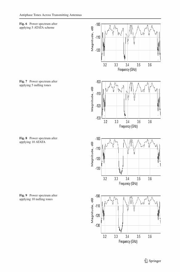
In Figs. 6, 7, 8 and 9, spectrum is analyzed at PU receiver by applying ATATA and nullingtones. Notch depth is observed in multipath environment. It is clear that the proposed schemecan produce notch depth comparable to tone nulling. Applying ATATA technique on morenumber of tones results in the deeper and wider notch.
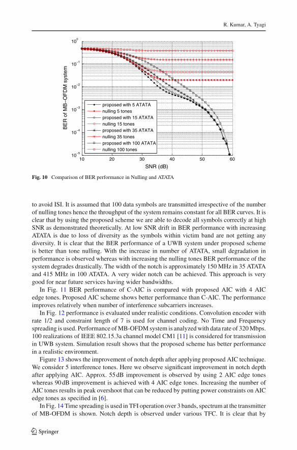
In Fig. 10 BER performance of MB-OFDM system is plotted so as to compare tone nullingand proposed ATATA schemes. We have considered first 32 multipath of UWB channel (CM1)
123
Antiphase Tones Across Transmitting Antennas
Fig. 6 Power spectrum afterapplying 5 ATATA scheme
Fig. 7 Power spectrum afterapplying 5 nulling tones
Fig. 8 Power spectrum afterapplying 10 ATATA
Fig. 9 Power spectrum afterapplying 10 nulling tones
123
R. Kumar, A. Tyagi
10 20 30 40 50 6010
−5
10−4
10−3
10−2
10−1
100
SNR (dB)
BE
R o
f MB
−O
FD
M s
yste
m
proposed with 5 ATATAnulling 5 tonesproposed with 15 ATATAnulling 15 tonesproposed with 35 ATATAnulling 35 tonesproposed with 100 ATATAnulling 100 tones
Fig. 10 Comparison of BER performance in Nulling and ATATA
to avoid ISI. It is assumed that 100 data symbols are transmitted irrespective of the numberof nulling tones hence the throughput of the system remains constant for all BER curves. It isclear that by using the proposed scheme we are able to decode all symbols correctly at highSNR as demonstrated theoretically. At low SNR drift in BER performance with increasingATATA is due to loss of diversity as the symbols within victim band are not getting anydiversity. It is clear that the BER performance of a UWB system under proposed schemeis better than tone nulling. With the increase in number of ATATA, small degradation inperformance is observed whereas with increasing the nulling tones BER performance of thesystem degrades drastically. The width of the notch is approximately 150 MHz in 35 ATATAand 415 MHz in 100 ATATA. A very wider notch can be achieved. This approach is verygood for near future services having wider bandwidths.
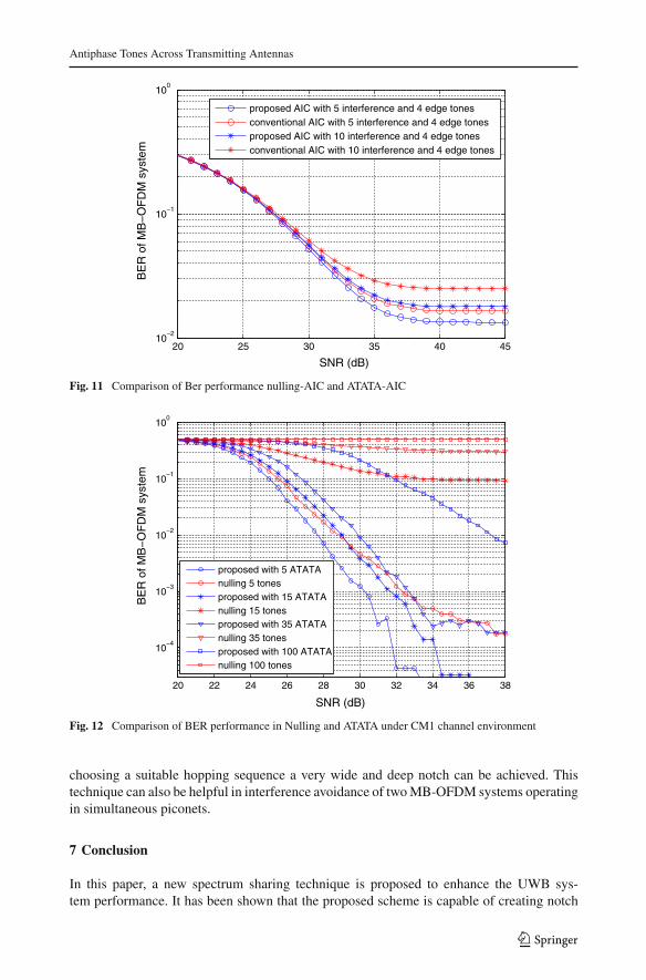
In Fig. 11 BER performance of C-AIC is compared with proposed AIC with 4 AICedge tones. Proposed AIC scheme shows better performance than C-AIC. The performanceimproves relatively when number of interference subcarriers increases.
In Fig. 12 performance is evaluated under realistic conditions. Convolution encoder withrate 1/2 and constraint length of 7 is used for channel coding. No Time and Frequencyspreading is used. Performance of MB-OFDM system is analyzed with data rate of 320 Mbps.100 realizations of IEEE 802.15.3a channel model CM1 [11] is considered for transmissionin UWB system. Simulation result shows that the proposed scheme has better performancein a realistic environment.
Figure 13 shows the improvement of notch depth after applying proposed AIC technique.We consider 5 interference tones. Here we observe significant improvement in notch depthafter applying AIC. Approx. 55 dB improvement is observed by using 2 AIC edge toneswhereas 90 dB improvement is achieved with 4 AIC edge tones. Increasing the number ofAIC tones results in peak overshoot that can be reduced by putting power constraints on AICedge tones as specified in [6].
In Fig. 14 Time spreading is used in TFI operation over 3 bands, spectrum at the transmitterof MB-OFDM is shown. Notch depth is observed under various TFC. It is clear that by
123
Antiphase Tones Across Transmitting Antennas
20 25 30 35 40 4510
−2
10−1
100
SNR (dB)
BE
R o
f MB
−O
FD
M s
yste
m
proposed AIC with 5 interference and 4 edge tones conventional AIC with 5 interference and 4 edge tones proposed AIC with 10 interference and 4 edge tones conventional AIC with 10 interference and 4 edge tones
Fig. 11 Comparison of Ber performance nulling-AIC and ATATA-AIC
20 22 24 26 28 30 32 34 36 38
10−4
10−3
10−2
10−1
100
SNR (dB)
BE
R o
f MB
−O
FD
M s
yste
m
proposed with 5 ATATAnulling 5 tonesproposed with 15 ATATAnulling 15 tonesproposed with 35 ATATAnulling 35 tonesproposed with 100 ATATAnulling 100 tones
Fig. 12 Comparison of BER performance in Nulling and ATATA under CM1 channel environment
choosing a suitable hopping sequence a very wide and deep notch can be achieved. Thistechnique can also be helpful in interference avoidance of two MB-OFDM systems operatingin simultaneous piconets.
7 Conclusion
In this paper, a new spectrum sharing technique is proposed to enhance the UWB sys-tem performance. It has been shown that the proposed scheme is capable of creating notch
123

R. Kumar, A. Tyagi
Fig. 13 Power spectrum of ATATA-AIC
Fig. 14 Effect of hop sequence (3 band operation) on notch depth
that is comparable to previous techniques and performance of UWB system is significantlyimproved. It can produce a very wide notch, so the scope of the scheme is not only limited tonarrowband interference cancellation but can be extended to wider band systems which maybe the case in near future. In this paper, we have shown that the symbols within and outsidethe victim band can be decoded by the same algorithm. This scheme can be implementedeasily with slight modification at the transmitter without affecting any current specifications.
References
1. Haykin, S. (2005). Cognitive radio: Brain-empowered wireless communications selected areas in com-munications. IEEE Journal on Selected Areas in Communications, 23(2), 201,220.
2. Batra, A., et al. (2005). Multiband OFDM physical layer specification. WiMedia Alliance, Release, 1, 1.3. Batra, A., Lingam, S., & Balakrishnan, J. (2006). Multi-band OFDM: A cognitive radio for UWB. Circuits
and systems, 2006. ISCAS 2006. Proceedings. 2006 IEEE international symposium on, pp. 4, pp. 4097,21–24 May 2006.
4. Yamaguchi, H. (2004). Active interference cancellation technique for MBOFDM cognitive radio. InMicrowave conference, 2004. 34th European, pp. 1105–1108.
5. Sarabchi, F., & Nerguizian, C. (2010). Interference cancellation technique for MIMO MB-OFDM UWBcognitive radio. Wireless and mobile communications (ICWMC), 6th international conference on, pp.472, 477, 20–25 Sep 2010.
6. Mahmoud, H. A., & Arslan, H. (2008). Sidelobe suppression in OFDM- based spectrum sharing systemsusing adaptive symbol transition. IEEE Communications Letters, 12(2), 133–135.
7. Alamouti, S. (1998). A simple transmit diversity technique for wireless communications. IEEE Journalon Selected Areas in Communications, 16, 1451–1458.
123
Antiphase Tones Across Transmitting Antennas
8. Tan, T. H., & Lin, K. C. (2006). Performance of space-time block coded MB-OFDM UWB systems. In:Proceedings of the 4th annual communication networks and services research conference (CSNR’06),pp. 323–327.
9. Tran, L. C., & Mertins, A. (2009). Space-time-frequency code implementation in MB-OFDM UWBcommunications: Design criteria and performance. IEEE Transactions on Wireless Communications,8(2), 701–713.
10. Foerster, J. R. (2003). Channel modeling sub-committee report final. In Technical Report P802.1502/490r1, IEEE 802.15 SG3a.
11. Tran, L. C., & Mertins, A. (2008). On the use of quasi-orthogonal space-time-frequency codes in MB-OFDM UWB. Communications and electronics, 2008. ICCE 2008. Second international conference on,pp. 252–257, 4–6 June 2008.
12. Alian, E. H. M., Saffar, H. E., & Mitran, P. (2012). Cross-band interference reduction trade-offs in SISOand MISO OFDM-based cognitive radios. IEEE Transactions on Wireless Communications, 11(7), 2436–2445.
Ravinder Kumar received B.Tech (E&CE) from National Institute ofTechnology Srinagar (J&K) in 2011 and M.Tech (Communication Sys-tem) from Indian Institute Of Technology Roorkee in 2013. Currentlyhe is working towards his Ph.D. Degree in Indian Institute of Technol-ogy Roorkee. His research area includes Cognitive radio, Interferencecancellation and OFDM.
Anshul Tyagi received his B.Tech (Electrical Engineering) and Ph.D.(Communication Engineering) degrees from Indian Institute of Tech-nology Delhi in 1997 and 2006 respectively. Currently he is working asan Assistant Professor in the Department of E&CE in Indian Instituteof Technology Roorkee. His research area includes Digital Communi-cations, Error Control Coding and UWB Communications.
123