Antennas With With Two Direction Patterns
11
654 IEEE TRANSACTIONS ON ANTENNAS AND PROPAGATION, VOL. 60, NO. 2, FEBRUARY 2012 MIMO Transmission Using a Single RF Source: Theory and Antenna Design Osama N. Alrabadi, Member, IEEE, Julien Perruisseau-Carrier, Member, IEEE, and Antonis Kalis, Senior Member, IEEE AbstractAn approach for transmitting multiple signals using a single switched parasitic antenna (SPA) has been recently reported. The idea there is to map the signals to be transmitted onto a set of basis functions that serve as virtual antennas in the beamspace (i.e., wavevector) domain. In this paper, we generalize the deriva- tion of the antenna pattern basis functions regarding a three-el- ement SPA of arbitrary radiating elements, within a symmetric array topology, for multiplexing signals in the wavevector domain (using different beampatterns) rather than in the hardware an- tenna domain with multiple feeding ports. A fully operational an- tenna system example is modeled, optimized regarding its return loss and the power imbalance between the basis functions, and - nally realized. The measurements of the SPA show good agreement with the simulated target values, revealing an accurate design ap- proach to be adopted as a fast SPA prototyping methodology. The SPA has been successfully employed for multiplexing two binary phase-shift-keying (BPSK) datastreams over-the-air, thus paving the way for practically compact and highly efcient MIMO trans- ceiver designs. Index TermsBasis functions, MIMO, recongurable antenna, switched parasitic antenna. I. INTRODUCTION M ULTI-INPUT MULTI-OUTPUT (MIMO) communica- tion has gained lots of attention over the last decade as it enhances the spectral efciency by exploiting the precious spatial resource dimension [1], [2]. Since the emergence of this technology, the classical approach has been assuming a trans- mitter with a number of transmit RF chains in order to inde- pendently map a set of signals onto a corresponding set of an- tennas. The receiver on the other hand performs some complex signal processing so as to decode the linear mixture of the sig- nals and extract the useful data. However, having multiple RF Manuscript received May 14, 2010; revised August 29, 2011; accepted September 02, 2011. Date of publication October 25, 2011; date of current version February 03, 2012. The work of J. Perruisseau-Carrier was supported by the Swiss National Science Foundation (SNSF) through its Professorship program. O. N. Alrabadi is with the Antennas, Propagation and Radio Networking (APNet) Group, Department of Electronic Systems, Aalborg University, DK-9220 Aalborg, Denmark (e-mail: [email protected]). J. Perruisseau-Carrier is with the Group for Adaptive MicroNano Wave Systems, LEMA/Nanolab, Ecole Polytechnique Fédérale de Lausanne (EPFL), Lausanne CH-1015, Switzerland (e-mail: julien.perruisseau-carrier@ep.ch). A. Kalis is with the Broadband Wireless and Sensor Networks (BWiSE) Group, Athens Information Technology (AIT), GR-19002, Athens, Greece (e-mail: [email protected]). Color versions of one or more of the gures in this paper are available online at http://ieeexplore.ieee.org. Digital Object Identier 10.1109/TAP.2011.2173429 chains at the user mobile terminal is rather costly. For example, the LTERelease 8 standard supports a single antenna for the up- link transmission and two antennas for the downlink reception [3], [4]. The asymmetry in the number of antennas is mainly in- tended for avoiding the costly power ampliers in the transmit RF chains. Although antenna selection is a terminal option, it requires instantaneous channel state information from the re- ceiver back to the transmitter, which is a burden on the wireless communication system. Consequently, classical MIMO trans- mission especially in uplink scenarios may not be supported due to the practical limitations of the portable RF units. To overcome these challenges, the authors in [5] describe how a half rate space-time (ST) code is transmitted with a single radio. In fact, a simple time-switched ST code [6] will outper- form the approach in [5] regarding both performance and com- plexity. In [7], the authors propose an antenna system of two RF sources and four antenna elements. The proposed antenna system is capable of changing its polarization state (at the mod- ulation rate), and thus transmitting the 4 4 Jafarkhani code. However, having two transmit RF chains may still be costly for low-end terminals. On the other hand, the authors in [8] proposed a MIMO-like system using a switched parasitic antenna (SPA) with a single RF source. The SPA was shown to have a throughput potential comparable to that of conventional MIMO systems by switching the SPA far-eld at the modulation rate, however no specic multiplexing techniques were proposed. In fact, parasitic an- tenna systems have been proposed over the past as a promising solution for addressing the problems associated with the dif- culty of integrating multiple RF chains in compact portable units [9]. Such antenna systems comprise a single RF branch and multiple antenna elements loaded by variable reactive im- pedances. By controlling the reactance via a dc control, basic antenna properties, like the beampattern, can be recongured. Parasitic antennas have been widely used for providing receive angular (or pattern) diversity (examples are given in [10] and [11]) and have recently been proposed for analogue beam and null steering [12]. The use of a compact-sized SPA for emulating open-loop MIMO transmission has been rst proposed in the work of Kalis et al. in [13] followed by work of Alrabadi et al. [14]. The idea of using an SPA as a MIMO terminal is to drive the central active antenna with a high frequency RF signal modulated by the rst datastream, while simultaneously driving a set of parasitic ele- ments (PEs) strongly coupled to the active one with a baseband (low frequency) control signal as shown in Fig. 1. The baseband control signal has information about the other datastreams to be 0018-926X/$26.00 © 2011 IEEE
-
Upload
andrey-shokotko -
Category
Documents
-
view
17 -
download
0
Transcript of Antennas With With Two Direction Patterns
654 IEEE TRANSACTIONS ON ANTENNAS AND PROPAGATION, VOL. 60, NO. 2, FEBRUARY 2012
MIMO Transmission Using a Single RF Source:Theory and Antenna Design
Osama N. Alrabadi, Member, IEEE, Julien Perruisseau-Carrier, Member, IEEE, andAntonis Kalis, Senior Member, IEEE
Abstract�An approach for transmitting multiple signals using asingle switched parasitic antenna (SPA) has been recently reported.The idea there is to map the signals to be transmitted onto a set ofbasis functions that serve as �virtual antennas� in the beamspace(i.e., wavevector) domain. In this paper, we generalize the deriva-tion of the antenna pattern basis functions regarding a three-el-ement SPA of arbitrary radiating elements, within a symmetricarray topology, for multiplexing signals in the wavevector domain(using different beampatterns) rather than in the hardware an-tenna domain with multiple feeding ports. A fully operational an-tenna system example is modeled, optimized regarding its returnloss and the power imbalance between the basis functions, and -nally realized. The measurements of the SPA show good agreementwith the simulated target values, revealing an accurate design ap-proach to be adopted as a fast SPA prototyping methodology. TheSPA has been successfully employed for multiplexing two binaryphase-shift-keying (BPSK) datastreams over-the-air, thus pavingthe way for practically compact and highly efcient MIMO trans-ceiver designs.
Index Terms�Basis functions, MIMO, recongurable antenna,switched parasitic antenna.
I. INTRODUCTION
M ULTI-INPUT MULTI-OUTPUT (MIMO) communica-tion has gained lots of attention over the last decade as
it enhances the spectral efciency by exploiting the preciousspatial resource dimension [1], [2]. Since the emergence of thistechnology, the classical approach has been assuming a trans-mitter with a number of transmit RF chains in order to inde-pendently map a set of signals onto a corresponding set of an-tennas. The receiver on the other hand performs some complexsignal processing so as to decode the linear mixture of the sig-nals and extract the useful data. However, having multiple RF
Manuscript received May 14, 2010; revised August 29, 2011; acceptedSeptember 02, 2011. Date of publication October 25, 2011; date of currentversion February 03, 2012. The work of J. Perruisseau-Carrier was supportedby the Swiss National Science Foundation (SNSF) through its Professorshipprogram.O. N. Alrabadi is with the Antennas, Propagation and Radio Networking
(APNet) Group, Department of Electronic Systems, Aalborg University,DK-9220 Aalborg, Denmark (e-mail: [email protected]).J. Perruisseau-Carrier is with the Group for Adaptive MicroNano Wave
Systems, LEMA/Nanolab, Ecole Polytechnique Fédérale de Lausanne (EPFL),Lausanne CH-1015, Switzerland (e-mail: [email protected]).A. Kalis is with the Broadband Wireless and Sensor Networks (BWiSE)
Group, Athens Information Technology (AIT), GR-19002, Athens, Greece(e-mail: [email protected]).Color versions of one or more of the gures in this paper are available online
at http://ieeexplore.ieee.org.Digital Object Identier 10.1109/TAP.2011.2173429
chains at the user mobile terminal is rather costly. For example,the LTE�Release 8 standard supports a single antenna for the up-link transmission and two antennas for the downlink reception[3], [4]. The asymmetry in the number of antennas is mainly in-tended for avoiding the costly power ampliers in the transmitRF chains. Although antenna selection is a terminal option, itrequires instantaneous channel state information from the re-ceiver back to the transmitter, which is a burden on the wirelesscommunication system. Consequently, classical MIMO trans-mission especially in uplink scenarios may not be supported dueto the practical limitations of the portable RF units.To overcome these challenges, the authors in [5] describe how
a half rate space-time (ST) code is transmitted with a singleradio. In fact, a simple time-switched ST code [6] will outper-form the approach in [5] regarding both performance and com-plexity. In [7], the authors propose an antenna system of twoRF sources and four antenna elements. The proposed antennasystem is capable of changing its polarization state (at the mod-ulation rate), and thus transmitting the 4 4 Jafarkhani code.However, having two transmit RF chains may still be costly forlow-end terminals.On the other hand, the authors in [8] proposed a MIMO-like
system using a switched parasitic antenna (SPA) with a singleRF source. The SPA was shown to have a throughput potentialcomparable to that of conventionalMIMO systems by switchingthe SPA far-eld at the modulation rate, however no specicmultiplexing techniques were proposed. In fact, parasitic an-tenna systems have been proposed over the past as a promisingsolution for addressing the problems associated with the dif-culty of integrating multiple RF chains in compact portableunits [9]. Such antenna systems comprise a single RF branchand multiple antenna elements loaded by variable reactive im-pedances. By controlling the reactance via a dc control, basicantenna properties, like the beampattern, can be recongured.Parasitic antennas have been widely used for providing receiveangular (or pattern) diversity (examples are given in [10] and[11]) and have recently been proposed for analogue beam andnull steering [12].The use of a compact-sized SPA for emulating open-loop
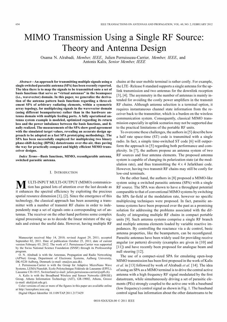
MIMO transmission has been rst proposed in the work of Kaliset al. in [13] followed by work of Alrabadi et al. [14]. The ideaof using an SPA as aMIMO terminal is to drive the central activeantenna with a high frequency RF signal modulated by the rstdatastream, while simultaneously driving a set of parasitic ele-ments (PEs) strongly coupled to the active one with a baseband(low frequency) control signal as shown in Fig. 1. The basebandcontrol signal has information about the other datastreams to be
0018-926X/$26.00 © 2011 IEEE
ALRABADI et al.: MIMO TRANSMISSION USING A SINGLE RF SOURCE: THEORY AND ANTENNA DESIGN 655
Fig. 1. Schematic diagram of the proposed technique where the rst bitstreamis modulated, up converted and fed into the central active element whereas thesecond bitstream is XORed with the rst one. The output control signal is usedfor swapping the loads of the PE.
transmitted over the air. By this way, it has been shown that theinput datastreams are mapped onto an orthogonal set of basisfunctions in the wavevector domain via a single radio and com-pact array dimensions.In this paper, we focus on binary phase-shift-keying (BPSK)
signaling format (the extension to all phase-shift keying (PSK)is straightforward by following the approach in [14]) wherewe rst generalize the derivation of the bases from mirrorimage pattern pairs (MIPPs) i.e., when one beampattern is amirrored version of the other, regardless of how the MIPPs areexpressed. We therefore extend previous ndings by decou-pling the wavevector domain [15] from the antenna domainand thus enabling MIMO functionality through any antennasystem capable of creating MIPPs. At the receiver side, weprove that the receive antenna response to a beampattern thatis a linear mixture of basis functions is nothing more thanthe linear combination of the receive antenna responses to thedifferent basis functions. By this way, the receiver decodesthe transmitted data symbols by estimating the basis responsesusing classical training techniques.A practical antenna system example of printed dipoles is pro-
posed, modeled, optimized regarding the average rate of trans-mission, and nally designed and demonstrated. The measuredreturn loss and radiation patterns are in good agreement withthe target parameters, revealing a fast and accurate designingmethodology.Throughout the paper, a bold small letter designates a
vector, and a bold big letter designates a matrix. The operatorsand designate complex conjugate, transpose, and
complex conjugate transpose (Hermitian) operators, respec-tively. The notation indicates an identity matrix of size
. The operator returns a square matrix with theelements of the vector laid across the main diagonal of thematrix. Moreover, we consider a classical uniform three-di-mensional angular power spectrum seen by the transmitter (themobile terminal), which is approximately the case when themobile unit is surrounded by many scatterers.The rest of the paper is organized as follows. In Section II, we
describe a technique for transmitting two BPSK signals simulta-neously via a single RF front end. Section III expresses the basisfunctions of a three-element SPA based on full-wave electro-magnetic modeling and optimizes the SPA for BPSK signalingregarding the average rate of transmission. Section IV describesan SPA example of printed dipoles and explains its design im-plementation. Section V shows both simulation and measure-ment results, and nally Section VI concludes the paper.
II. MIMO TRANSMISSION WITH A SINGLE RF SOURCE
In this section, we rst prove the existence of an orthog-onal basis whenever an MIPP can be formed. Based on this, atechnique for transmitting two BPSK signals using an arbitrarysingle radio based antenna system capable of forming an MIPPis described.
A. Orthogonal Bases Using an MIPP
The correlation between two arbitrary beampatternsand is given by
(1)
where
(2)
are the spatial integration of the power beampatterns ofand over the space, respectively. Whenever ,the two beampatterns are called �balanced.�Lemma 1: For an MIPP and , the set of the
angular functions dened as
(3)
form an orthogonal basis.Proof: For two beampatterns that form an MIPP, we have
since one beampattern is just a mirrored version of theother. Moreover, the correlation between the two beams is real

656 IEEE TRANSACTIONS ON ANTENNAS AND PROPAGATION, VOL. 60, NO. 2, FEBRUARY 2012
(see the proof in the Appendix), and thus . Based onthese observations, the proof is straightforward and is given asfollows:
(4)
Corollary 1: A balanced basis is obtained by designing thetwo beampatterns and described in Lemma 1to be orthogonal to each other, i.e., if and areorthonormal, and are orthonormal too.1
Proof: Letting , the proof is straight-forward, as shown in (6). In (6), and are the spatial inte-gration of the power beampatterns of and ,over the space, given, respectively, by
(5)
(6)
B. Transmission Technique Description
In this part, we show that an arbitrary antenna system that hasa single RF input but has the capability of creating an MIPP willbe capable of transmitting two BPSK signals and , simulta-neously. The two BPSK signals are mapped onto an orthogonalset of basis functions; thus, independent fading between the twosignals is almost always guaranteed regardless of the transceiver
1The reason that we acquire an orthonormal basis andfrom anMIPP is that theMIPP by itself represents a linear combination (desiredmultiplexing relation) of the basis onto which the signals are mapped. The di-versity action of the system directly depends on the transmit covariance of thebasis (proportional to the identity matrix when the basis is orthonormal).
TABLE ITWO BPSK SIGNALS COMBINATIONS
compactness. Letting the sole RF port be fed by the signal ,the antenna beampattern in the far-eld becomes either
State 1
or State 2
or generally as
(7a)
(7b)
where is the antenna system state such that is State1 within which the antenna system transmits over and
is State 2 within which the antenna system transmits over. From (7b), it is obvious how the two BPSK signals:
, which is modulated in the baseband, upconverted, and fedinto the input RF port and , which is spatiallymodulated on the antenna far-eld by controlling the antennastate , are mapped onto the space of and ,respectively. In general, for any PSK modulation of order
is a set of complex numbers evenly distributed over theunit circle, as discussed in Section IV of [12]. Table I shows thestate required for transmitting according to the value of ,where is input vector of bits modulated into .Fig. 1 shows a schematic diagram of the proposed technique,where the XORing of the two bitstreams gives the required ,i.e., giving 0 and 1, which correspond toand , respectively.
C. System Training
The two BPSK signals that are transmitted in the beam-spacedomain and received using a classical uniform linear array(ULA) of antenna elements ( -element ULA), can bedecoded by rst estimating the receive antenna responses to theproposed basis.Proposition 1: A beampattern comprising a linear mixture of
basis functions (at the transmitter side) triggers a linear combi-nation of the individual channel responses to the different basisfunctions (at the receiver side).
ALRABADI et al.: MIMO TRANSMISSION USING A SINGLE RF SOURCE: THEORY AND ANTENNA DESIGN 657
Proof: This directly stems from the principle of superposi-tion in linear systems. To have a deeper insight, we rst dene2 1 column vectors , and
, where the rst and the second elements of everycolumn vector represent the and polarizations of the cor-responding pattern, respectively. We also dene asthe vector of the polarization components of the th receiver an-tenna pattern . As in [16], we assume that the propa-gation channel between the transmitter and the receiver consistsof a set of plane waves, with the th wave characterized by acomplex voltage gain , angle of departure , andangle of arrival . We also assume that each planewave undergoes a polarization transformation due to scatteringthat can be expressed as the unitary matrix
(8)
The response of the th receive antenna when il-luminated by the beampattern is the complex channelgain representing the ratio of the received voltage signal to thetransmitted voltage signal and may be written as shown in (9),where is a constant that depends on the receiver and thetransmitter active gains and impedances [17], andare the responses of the th receive antenna to and
, respectively. By applying the same analysis, the re-sponse of the th receive antenna when illuminated bybecomes .
(9)
Based on this, the receiver can decode the two BPSK signals byestimating the channel responses of the basis as
(10a)
(10b)
By constructing the matrix of the receive antennas� responses,the receiver can zero-force the received signal by inverting thechannel matrix (or using any other reception techniques) for de-coding and .
III. ANTENNA MODEL AND OPTIMIZATION
In this paper, we adopt the antenna topology proposed in [14],i.e., a symmetrical three-element SPA, where the central ele-ment is the active one, while the other two are passive. Thetwo parasitic elements are loaded with pure imaginary loads
as the real part of a complex load degrades the ef-ciency of the antenna system. Obviously, the antenna systemcan create an MIPP (the plane in Fig. 1) by simply permutingthe reactive loads of the PE as , basedon image theory. In other words, having the rst beampattern
at , the beampatternis obtained at . Consequently, by feeding the centralactive element with the rst BPSK datastream and permutingthe loads according to the second datastream, the two streamsare simultaneously transmitted out of a single radio and mappedonto an orthogonal basis according to Lemma 1, irrespective of
and . Having the two loads and as a degree offreedomwhen considering BPSK signaling, we can optimize theloads according to a specic criterion as shown in Section III-C.
A. Generalized Derivation of Antenna Basis Functions
Although the beampattern of thin electrical dipoles (ormonopoles) can be practically approximated as an array factorby the superposition of the retarded currents induced on thewire antenna elements such as in [14, eq. (6)], this is not truewhen considering general2 radiating elements, e.g., at orfractal dipoles, slot antennas, etc. To overcome this problem,we implement full wave electromagnetic modeling basedon the SPA scattering parameters (S-parameters) denoted by
, as well as the 3D complex active portpatterns3 of the antenna elements 0, 1, and 2 shown in Fig. 1,denoted by and , respectively. Anexpression of the electric far-eld beampattern of a three-el-ement SPA based on the aforementioned quantities and thevariable antenna loading has been derived in [19] using Mason�srule. From [19] and after correcting the equations to properlyadhere to Mason�s rule, the two basis functions obtained whenswapping the imaginary loads of the two parasitic elementsbecome
(11)2Again, we emphasize that the arbitrariness of the elements is limited to the
center element being a self mirror image, and the outer two being respectivemirror images of each other, both about a vertical plane that divides the left andright sides of the SPA structure.
3The active port pattern is dened as the beampattern obtained when drivingthe corresponding port (whether being active or passive) with a unit excitationvoltage signal while terminating the other ports with reference impedances [18].
658 IEEE TRANSACTIONS ON ANTENNAS AND PROPAGATION, VOL. 60, NO. 2, FEBRUARY 2012
where
(12)
and such that
(13)
(14)
where we assumed by having the source impedance atthe central driven port equal to the reference impedance
. The basis coefcients in (12) are derived with respect toa general scattering matrix. Swapping the two reactive loadsas , swaps the coefcients
in (11), thus phase-shifting by180 without affecting . By this way, the factorin (7a) is obtained. The two functions andare the basis functions that are used to transmit two PSK signalsof any modulation order [14].
B. Received Signal Model
Considering a narrowband, at-fading, point-to-point com-munication link where the two BPSK symbols are transmitted inthe beam-space domain over two basis functions (equivalent totwo uncorrelated virtual antennas) and received using an -el-ement ULA of uncorrelated and uncoupled antenna elements.Assuming independent fading statistics at the transmitter andthe receiver, the Kronecker product [20] can be assumed andthus the channel transfer function can be written as4
(15)
where the elements of the matrix are inde-pendent and identically distributed (i.i.d.) complex Gaussianrandom variables with zero mean and unit variance. The cor-relation at the receiver side is ignored by the aforementionedassumptions regarding the receiving ULA. Dening the row
4In [21], the correlation based channel model accounts for the mutual cou-pling by explicitly incorporating the coupling matrices. However, in (15), themutual coupling is implicitly taken into consideration within the calculation ofthe basis functions in (11).
vector , the transmit covariancematrix5 is obtained as
(16)
which is simply the power distribution across the basis functionssince according to Lemma 1. Notice that
, which is easily obtained from (2) and thebasis denition in (3), where is the average transmit power.Dening the power imbalance ratio between the basis functionsas , we can write as , where is thenormalized power distribution across the basis functions suchthat . can be written as such that
and . From the above, the receivedsignal model becomes
(17)
where is the power into the transmitter (input power) andis the efciency of the transmit antenna system being
equal to , where is the SPA return loss derivedin [19]. Finally, is the vector of the modulatedBPSK signals (see Table I), and is a vector representing thewhite Gaussian noise, with zero mean and variance.
C. Optimization Criterion
In this paper, we dene the optimal SPA loads as the ones thatmaximize the average rate of transmission. However, in MIMOcommunications, average rate computation often demands tack-ling calculations of expectations with respect to random ma-trices rather than random scalar variables. For this reason, wederive an upperbound on the average rate and deploy it as anoptimization criterion. We assume open-loop operation wherethe channel is known to the receiver but unknown to the trans-mitter. The ergodic capacity of a MIMO random channel, de-noted by , is the ensemble average of the information rateover the distribution of the elements of the channel matrix
. By using the formula [22], theupper bound that comes from the Jensen�s inequality and theconcavity of ,6 we get
5Since the basis functions are imbalanced, the transmit covariance matrixrather than the transmit correlation matrix is considered.
6The is concave over positive semi-denite matrices [23]. Sinceis positive semi-denite, the term is positive semi-
denite too, as it is a one-to-one mapping of , thus preserving the positivedeniteness.
ALRABADI et al.: MIMO TRANSMISSION USING A SINGLE RF SOURCE: THEORY AND ANTENNA DESIGN 659
(18)
In (18), the average transmitted power is not divided by thenumber of the basis functions (the number of the virtual an-tennas), since the trace of is normalized to a unity rather thanto the number of the basis functions (both forms are equivalent).The optimal loading is dened as the one that maximizes the av-erage throughput upperbound in (18), i.e.,
(19)
In (19), is made part of the optimization criterion by con-straining rather than as the SPA efciency is a key de-sign parameter when considering portable RF units with limitedstorage batteries.
IV. ANTENNA SYSTEM DESIGN
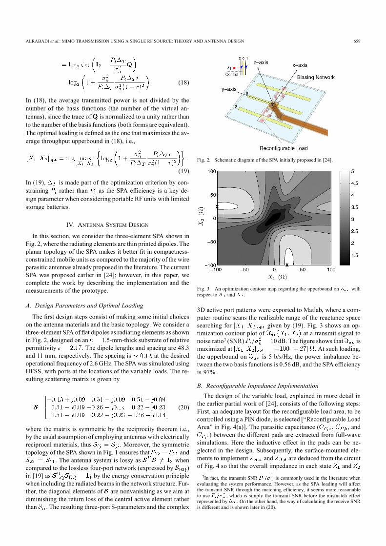
In this section, we consider the three-element SPA shown inFig. 2, where the radiating elements are thin printed dipoles. Theplanar topology of the SPA makes it better t in compactness-constrained mobile units as compared to the majority of the wireparasitic antennas already proposed in the literature. The currentSPA was proposed earlier in [24]; however, in this paper, wecomplete the work by describing the implementation and themeasurements of the prototype.
A. Design Parameters and Optimal Loading
The rst design steps consist of making some initial choiceson the antenna materials and the basic topology. We consider athree-element SPA of at dipoles as radiating elements as shownin Fig. 2, designed on an 1.5-mm-thick substrate of relativepermittivity . The dipole lengths and spacing are 48.3and 11 mm, respectively. The spacing is at the desiredoperational frequency of 2.6 GHz. The SPAwas simulated usingHFSS, with ports at the locations of the variable loads. The re-sulting scattering matrix is given by
(20)
where the matrix is symmetric by the reciprocity theorem i.e.,by the usual assumption of employing antennas with electricallyreciprocal materials, thus . Moreover, the symmetrictopology of the SPA shown in Fig. 1 ensures that and
. The antenna system is lossy as whencompared to the lossless four-port network (expressed by )in [19] as by the energy conservation principlewhen including the radiated beams in the network structure. Fur-ther, the diagonal elements of are nonvanishing as we aim atdiminishing the return loss of the central active element ratherthan . The resulting three-port S-parameters and the complex
Fig. 2. Schematic diagram of the SPA initially proposed in [24].
Fig. 3. An optimization contour map regarding the upperbound on withrespect to and .
3D active port patterns were exported to Matlab, where a com-puter routine scans the realizable range of the reactance spacesearching for given by (19). Fig. 3 shows an op-timization contour plot of at a transmit signal tonoise ratio7 (SNR) 10 dB. The gure shows that ismaximized at . At such loading,the upperbound on is 5 b/s/Hz, the power imbalance be-tween the two basis functions is 0.56 dB, and the SPA efciencyis 97%.
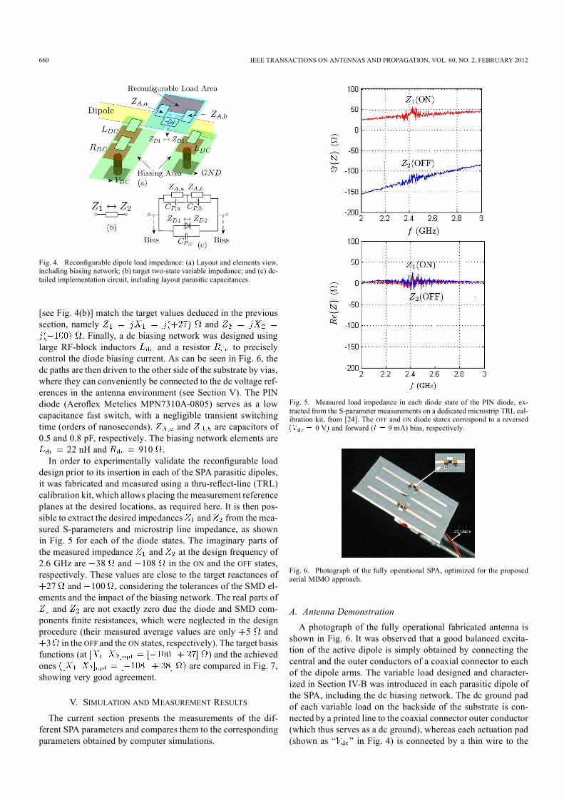
B. Recongurable Impedance ImplementationThe design of the variable load, explained in more detail in
the earlier partial work of [24], consists of the following steps:First, an adequate layout for the recongurable load area, to becontrolled using a PIN diode, is selected [�Recongurable LoadArea� in Fig. 4(a)]. The parasitic capacitance ( , and
) between the different pads are extracted from full-wavesimulations. Here the inductive effect in the pads can be ne-glected in the design. Subsequently, the surface-mounted ele-ments to implement and are deduced from the circuitof Fig. 4 so that the overall impedance in each state and
7In fact, the transmit SNR is commonly used in the literature whenevaluating the system performance. However, as the SPA loading will affectthe transmit SNR through the matching efciency, it seems more reasonableto use , which is simply the transmit SNR before the mismatch effectrepresented by . On the other hand, the way of calculating the receive SNRis different and is shown later in (20).
660 IEEE TRANSACTIONS ON ANTENNAS AND PROPAGATION, VOL. 60, NO. 2, FEBRUARY 2012
Fig. 4. Recongurable dipole load impedance: (a) Layout and elements view,including biasing network; (b) target two-state variable impedance; and (c) de-tailed implementation circuit, including layout parasitic capacitances.
[see Fig. 4(b)] match the target values deduced in the previoussection, namely and
. Finally, a dc biasing network was designed usinglarge RF-block inductors and a resistor to preciselycontrol the diode biasing current. As can be seen in Fig. 6, thedc paths are then driven to the other side of the substrate by vias,where they can conveniently be connected to the dc voltage ref-erences in the antenna environment (see Section V). The PINdiode (Aeroex Metelics MPN7310A-0805) serves as a lowcapacitance fast switch, with a negligible transient switchingtime (orders of nanoseconds). and are capacitors of0.5 and 0.8 pF, respectively. The biasing network elements are
22 nH and 910 .In order to experimentally validate the recongurable load
design prior to its insertion in each of the SPA parasitic dipoles,it was fabricated and measured using a thru-reect-line (TRL)calibration kit, which allows placing the measurement referenceplanes at the desired locations, as required here. It is then pos-sible to extract the desired impedances and from the mea-sured S-parameters and microstrip line impedance, as shownin Fig. 5 for each of the diode states. The imaginary parts ofthe measured impedance and at the design frequency of2.6 GHz are 38 and 108 in the ON and the OFF states,respectively. These values are close to the target reactances of27 and 100 , considering the tolerances of the SMD el-
ements and the impact of the biasing network. The real parts ofand are not exactly zero due the diode and SMD com-
ponents nite resistances, which were neglected in the designprocedure (their measured average values are only 5 and3 in the OFF and the ON states, respectively). The target basis
functions (at ) and the achievedones are compared in Fig. 7,showing very good agreement.
V. SIMULATION AND MEASUREMENT RESULTS
The current section presents the measurements of the dif-ferent SPA parameters and compares them to the correspondingparameters obtained by computer simulations.
Fig. 5. Measured load impedance in each diode state of the PIN diode, ex-tracted from the S-parameter measurements on a dedicated microstrip TRL cal-ibration kit, from [24]. The OFF and ON diode states correspond to a reversed
0 V and forward ( 9 mA) bias, respectively.
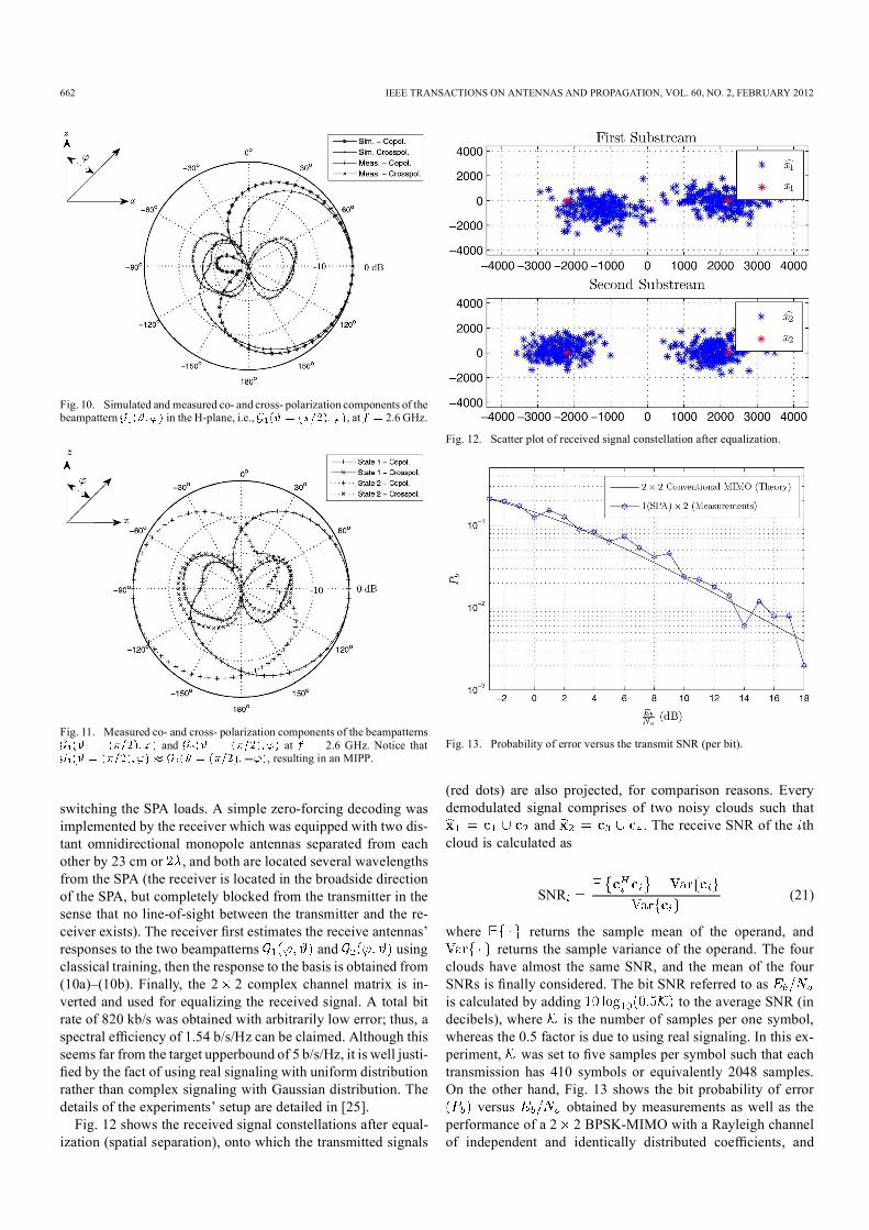
Fig. 6. Photograph of the fully operational SPA, optimized for the proposedaerial MIMO approach.
A. Antenna DemonstrationA photograph of the fully operational fabricated antenna is
shown in Fig. 6. It was observed that a good balanced excita-tion of the active dipole is simply obtained by connecting thecentral and the outer conductors of a coaxial connector to eachof the dipole arms. The variable load designed and character-ized in Section IV-B was introduced in each parasitic dipole ofthe SPA, including the dc biasing network. The dc ground padof each variable load on the backside of the substrate is con-nected by a printed line to the coaxial connector outer conductor(which thus serves as a dc ground), whereas each actuation pad(shown as � � in Fig. 4) is connected by a thin wire to the

ALRABADI et al.: MIMO TRANSMISSION USING A SINGLE RF SOURCE: THEORY AND ANTENNA DESIGN 661
Fig. 7. The magnitude of the H-plane co- polarized basis functions at the targetloads of and at the practically achieved loads of .The two basis functions resemble the omni and the angular sine functions, whichare orthogonal to each other.
Fig. 8. Setup of the antenna for recongurable radiation pattern measurements,with a 9-V battery places behind the absorber cone in a direction of the low eldintensity.
bias voltages for controlling the states of the diodes. In order toimprove the antenna performance and provide pure measuredpatterns, the dc wires are driven along the coaxial feed, whichis oriented toward the minimum radiation of the SPA (i.e., par-allel to the dipoles, see Fig. 6). A standard 9-V battery is used asa dc source in the radiation pattern measurements. The batteryis placed behind a piece of an absorber (located in the directionof minimum radiated power density), as can be seen in Fig. 8.Therefore the antenna states were simply selected by connectingeach of the two dc wires to the 0 or 9 V references. The impactof the biasing voltages on the antenna performance was investi-gated, showing similar responses for 10 to 0 V as the OFF (or�reverse-biased�) state, while 3 V to 10 V are acceptable forthe ON (or �forward-biased�) state.
B. Return LossFig. 9 shows the simulated and measured return loss of the
SPA around the design frequency of 2.6 GHz. The graph onlyshows the response in the operational states of the antenna,namely when it is loaded by the reactance load pairsand . As explained earlier in Section IV, the returnloss is the same for both states due to the SPA symmetry, whichis conrmed here by the similarity between the two measured
Fig. 9. Return loss (dB) of the SPA for both loading states, i.e., and.
curves in Fig. 9. The SPA was found to have poor matchingin the two (unused) states and ), whichare not shown here. The agreement between simulations andthe measurements is moderate, since the measured bandwidthis larger than the one obtained by simulation and is not exactlycentered around the design frequency of 2.6 GHz. Neverthe-less the measurements show good return loss at 2.6 GHz. The10-dB measured bandwidth is 5.6% and 7.1% for a reference
of 10 dB, for and , respectively.
C. Radiation PatternsFig. 10 shows the H-plane co- and cross- polarized far
elds in the rst operational antenna state . Notethat the maximum of the co-polarized beampattern, located at
90 , corresponds to the direction of the load in the OFFstate. The simulated and measured co- and cross- polarizedbeampatterns are in good agreement, as shown in Fig. 10.Because of the SPA symmetrical structure and the reactancepair antisymmetry, the other antenna beampattern shouldsimply be a mirror image of the rst beampattern around the
0 180 axis, which is well veried by the measuredprototype, as can be seen in Fig. 11.
D. Experimental ResultsThe proposed antenna prototype has been successfully used
for spatially multiplexing two BPSK datastreams over the airat 2.6 GHz. The experiments constitute to the best of the au-thors� knowledge the rst MIMO transmission with a single RFsource yet to be proposed. The rst train was modulated intoa BPSK symbol stream (using a raised-cosine waveform with0.3 roll-off factor) and upconverted to 2.6 GHz. The high fre-quency signal was modulated to the central element within amodulation bandwidth of 533 kHz. The second binary train wasXORed with the rst binary train in the baseband domain andthe output baseband control signal was amplied and used for
662 IEEE TRANSACTIONS ON ANTENNAS AND PROPAGATION, VOL. 60, NO. 2, FEBRUARY 2012
Fig. 10. Simulated and measured co- and cross- polarization components of thebeampattern in the H-plane, i.e., , at 2.6 GHz.
Fig. 11. Measured co- and cross- polarization components of the beampatternsand at 2.6 GHz. Notice that
, resulting in an MIPP.
switching the SPA loads. A simple zero-forcing decoding wasimplemented by the receiver which was equipped with two dis-tant omnidirectional monopole antennas separated from eachother by 23 cm or , and both are located several wavelengthsfrom the SPA (the receiver is located in the broadside directionof the SPA, but completely blocked from the transmitter in thesense that no line-of-sight between the transmitter and the re-ceiver exists). The receiver rst estimates the receive antennas�responses to the two beampatterns and usingclassical training, then the response to the basis is obtained from(10a)�(10b). Finally, the 2 2 complex channel matrix is in-verted and used for equalizing the received signal. A total bitrate of 820 kb/s was obtained with arbitrarily low error; thus, aspectral efciency of 1.54 b/s/Hz can be claimed. Although thisseems far from the target upperbound of 5 b/s/Hz, it is well justi-ed by the fact of using real signaling with uniform distributionrather than complex signaling with Gaussian distribution. Thedetails of the experiments� setup are detailed in [25].Fig. 12 shows the received signal constellations after equal-
ization (spatial separation), onto which the transmitted signals
Fig. 12. Scatter plot of received signal constellation after equalization.
Fig. 13. Probability of error versus the transmit SNR (per bit).
(red dots) are also projected, for comparison reasons. Everydemodulated signal comprises of two noisy clouds such that
and . The receive SNR of the thcloud is calculated as
SNR (21)
where returns the sample mean of the operand, andreturns the sample variance of the operand. The four
clouds have almost the same SNR, and the mean of the fourSNRs is nally considered. The bit SNR referred to asis calculated by adding to the average SNR (indecibels), where is the number of samples per one symbol,whereas the 0.5 factor is due to using real signaling. In this ex-periment, was set to ve samples per symbol such that eachtransmission has 410 symbols or equivalently 2048 samples.On the other hand, Fig. 13 shows the bit probability of error
versus obtained by measurements as well as theperformance of a 2 2 BPSK-MIMO with a Rayleigh channelof independent and identically distributed coefcients, and
ALRABADI et al.: MIMO TRANSMISSION USING A SINGLE RF SOURCE: THEORY AND ANTENNA DESIGN 663
zero-forcing decoding.8 The gure shows that the performanceof the beamspace MIMO is comparable to the conventionalone, thus validating the importance of such a new approach forrealizing single radio compact-sized MIMO transceivers.
VI. CONCLUSION
The paper generalized a previously reported approach fortransmitting multiple signals using a single RF source. The ideais to obtain an orthogonal or orthonormal basis out of MIPPs.The paper also provided design steps for an example of a three-element SPA, capable of forming an MIPP that are mirror im-ages of each other. The SPA was optimized for BPSK signalingby deriving a criterion that maximizes the SPA efciency andminimizes the power imbalance between the basis functions, si-multaneously. A recongurable impedance was designed and afully operational SPA for single radio MIMO transmission wasdemonstrated for the rst time. The measured SPA parametersare in good agreement with the target values, regarding the SPAreturn loss and the radiation patterns in the different SPA states.Finally, the SPA has been successfully used for multiplexingtwo BPSK datastreams with a total bit rate of 820 kb/s.
APPENDIX
In this part, we prove that the cross-correlation of an MIPP ina uniform eld is real.
Proof: Assuming an MIPP over the angular domain,where is the azimuth polar system of coordinates with a refer-ence axis taken from the MIPP axis of symmetry (the can bedropped for simplicity). The MIPP can generally be written as
and . The can be further writtenas , where and are the real andimaginary parts of . The cross-correlation of the MIPPbecomes
ACKNOWLEDGMENT
The authors like to thank P. Pardo for fabricating and mea-suring the variable load circuit, and P. Miskovsky for his help in
8Theoretically, of a 2 2 BPSK-MIMO under Rayleigh fading and a zero-forcing receiver is unsurprisingly identical to the performance of 1 1 BPSK-SISO i.e., [26].
the antenna measurement, both at Centre Tecnològic de Teleco-municacions de Catalunya (CTTC), Barcelona, Spain. Finally,the authors express their deepest gratitude to the editor and to theanonymous reviewers for their helpful and constructive com-ments and suggestions.
REFERENCES[1] J. H. Winters, �On the capacity of radio communication systems
with diversity in a Rayleigh fading environment,� IEEE J. Sel. AreasCommun., vol. SAC-5, pp. 871�878, Jun. 1987.
[2] G. J. Foschini and M. J. Gans, �Limits of wireless communication ina fading environment when using multiple antennas,� Wireless Pers.Commun., vol. 6, no. 3, pp. 311�335, 1998.
[3] Overview of 3GPP Release 8 V0.0.3, Nov. 2008 [Online]. Available:http://www.3gpp.org/Release-8, available online at
[4] J. Kotecha, �LTE:MIMO techniques in 3GPP-LTE,� Freescale Semi-conductor, Inc., Jun. 2008, available online.
[5] M. Okoniewski, S. V. Hum, A. Sutinjo, and G. G. Messier, �A space-time coding scheme utilizing phase shifting antennas at RF frequen-cies,� IEEEAntennasWireless Propag. Lett., vol. 4, pp. 369�372, 2005.
[6] J. Yuan and B. Vucetic, Space-Time Coding. NewYork: Wiley, 2003.[7] A. Grau, J. Romeu, M. Lee, S. Blanch, L. Jofre, and F. De Flaviis, �A
dual-linearly-polarizedMEMS-recongurable antenna for narrowbandMIMO communication systems,� IIEEE Trans. Antennas Propag., vol.58, no. 1, pp. 4�17, Jan. 2010.
[8] M. Wennstorm and T. Savantesson, �An antenna solution for MIMOchannels: The switched parasitic antenna,� in Proc. 12th IEEE Int.Symp. Pers., Indoor, Mobile Radio Commun., Sep. 2001, vol. 1, pp.159�163.
[9] R. Vaughan, �Switched parasitic elements for antenna diversity,�IIEEE Trans. Antennas Propag., vol. 47, no. 2, pp. 399�405, Feb.1999.
[10] T. Sawaya, K. Iigusa, M. Taromaru, and T. Ohira, �Reactance diver-sity: Proof-of-concept experiments in an indoor multipath-fading en-vironment with a 5-GHz prototype planar ESPAR antenna,� in Proc.Consumer Commun. Netw. Conf., Jan. 5�8, 2004, pp. 678�680.
[11] M. Yamamoto, M. Taromaru, H. Sadamichi, and A. Shimizu, �Per-formance of angle switch diversity using ESPAR antenna for mobilereception of terrestrial digital TV,� in Proc. IEEE 64th Veh. Technol.Conf. (VTC�Fall 2006), 2006, pp. 1�5.
[12] C. Sun, A. Hirata, T. Ohira, and N. C. Karmakar, �Fast beamformingof electronically steerable parasitic array radiator antennas: Theoryand experiment,� IIEEE Trans. Antennas Propag., vol. 52, no. 7, pp.1819�1832, Jul. 2004.
[13] A. Kalis, A. G. Kanatas, and C. B. Papadias, �A novel approach toMIMO transmission using a single RF front end,� IEEE J. Sel. AreasCommun., vol. 26, no. 6, pp. 972�980, Aug. 2008.
[14] O. N. Alrabadi, C. B. Papadias, A. Kalis, and R. Prasad, �A universalencoding scheme forMIMO transmission using a single active elementfor PSK modulation schemes,� IEEE Trans. Wireless Commun., vol. 8,no. 10, pp. 5133�5142, Oct. 2009.
[15] A. S. Y. Poon, R. W. Brodersen, and D. N. C. Tse, �Degrees of freedomin multiple-antenna channels: A signal space approach,� IEEE Trans.Inf. Theory, vol. 51, no. 2, pp. 523�536, Feb. 2005.
[16] M. L. Morris and M. A. Jensen, �Network model for MIMO systemswith coupled antennas and noisy ampliers,� IEEE Trans. AntennasPropag., vol. 53, no. 1, pp. 545�552, Jan. 2005.
[17] C. Waldschmidt, S. Schulteis, and W. Wiesbeck, �Complete RFsystem model for analysis of compact MIMO arrays,� IEEE Trans.Veh. Technol., vol. 53, no. 3, pp. 579�586, May 2004.
[18] D. M. Pozar, �The active element pattern,� IEEE Trans. AntennasPropag., vol. 42, no. 8, pp. 1176�1178, Aug. 1994.
[19] L. Petit, L. Dussopt, and J. Laheurte, �MEMS-switched parasitic-an-tenna array for radiation pattern diversity,� IIEEE Trans. AntennasPropag., vol. 54, no. 9, pp. 2624�2631, Sep. 2006.
[20] D. S. Shiu, G. J. Foschini, M. J. Gans, and J. M. Kahn, �Fading corre-lation and its effect on the capacity of multielement antenna systems,�IEEE Trans. Commun., vol. 48, no. 3, pp. 502�513, Mar. 2000.
[21] Y. Fei, Y. Fan, B. K. Lau, and J. S. Thompson, �Optimal single-portmatching impedance for capacity maximization in compact MIMO ar-rays,� IEEE Trans. Antennas Propag., vol. 56, no. 11, pp. 3566�3575,Nov. 2008.
664 IEEE TRANSACTIONS ON ANTENNAS AND PROPAGATION, VOL. 60, NO. 2, FEBRUARY 2012
[22] A. Paulraj, R. Nabar, and D. Gore, Introduction to Space-TimeWirelessCommunications. Cambridge, U.K.: Cambridge Univ. Press, 2003.
[23] R. A. Horn, Matrix Analysis. Cambridge, U.K.: Cambridge Univ.Press, 1996.
[24] J. Perruisseau-Carrier, O. N. Alrabadi, and A. Kalis, �Implementationof a recongurable parasitic antenna for beam-space BPSK transmis-sions,� in Proc. Eur. Microw. Conf. (EuMA), Paris, France, Sep. 2010,pp. 644�647.
[25] O. N. Alrabadi et al., �Spatial multiplexing with a single radio:Proof-of-concept experiments in an indoor environment with a 2.6GHz prototype,� IEEE Commun. Lett., vol. 15, no. 2, pp. 178�180,Dec. 17, 2010.
[26] D. Tse and P. Viswanath, Fundamentals ofWireless Communication.Cambridge, U.K.: Cambridge Univ. Press, 2005.
Osama N. Alrabadi (M�10) was born in Jordanin 1979. He received the Electrical EngineeringDiploma from the University of Jordan (JU),Amman, in 2002, the Master�s degree in informationand telecommunications (M.S.I.T.T.) (with highesthons.) from Athens Information Technology (AIT),Greece, in 2007, and the Ph.D. degree from AalborgUniversity (AAU), Denmark, in 2011.In 2001, he joined Orange Mobile (previously
MobileCom) for undergraduate training in theMicrowave and GSM Network Maintenance De-
partment. From 2002 to 2006, he was working at the National Electrical PowerCompany (NEPCO) and the Jordan Electrical Power Company (JEPCO) inremote control, metering, and communications. He is currently a PostdoctoralFellow at the Antennas, Propagation and Radio Networking (APNet) group atAAU. He is currently working on the Smart Antenna Frontend (SAFE) project,in cooperation with the antenna company Molex, the tuner company Wispry,Irvine, CA, and Intel Mobile Communications. His research interests includedesign and modeling of small antenna arrays, space�time signal processing, aswell as MIMO and cognitive radio transceiver architectures.Dr. Alrabadi has been a member of the Jordan Engineering Association since
2002.
Julien Perruisseau-Carrier (S�07�M�09) was bornin Lausanne, Switzerland, in 1979. He receivedthe M.Sc. and Ph.D. degrees from the Ecole Poly-technique Fédérale de Lausanne (EPFL), Lausanne,Switzerland, in 2003 and 2007, respectively.In 2003, he was with the University of Birm-
ingham, U.K., rst as a visiting EPFL M.Sc. studentand then as a short-term researcher. From 2004 to2007, he was with the Laboratory of Electromag-netics and Acoustics (LEMA), EPFL, where hecompleted his Ph.D. while working on various EU
funded projects. From 2007 to 2011, he was an Associate Researcher with theCentre Tecnològic de Telecomunicacions de Catalunya (CTTC), Barcelona,Spain. Since June 2011, he has been a Professor at EPFL funded by the SwissNational Science Foundation (SNSF), where he leads the group for AdaptiveMicroNano Wave Systems. He has led various projects and work packagesat the National, European Space Agency, European, and industrial levels.He has authored more than 50 conference papers and more than 20 journalpapers. His main research interest concerns interdisciplinary topics relatedto electromagnetic micro- and millimeter-waves: dynamic reconguration,application of micro/nanotechnology, metamaterials, and joint antenna-codingtechniques.Prof. Perruisseau-Carrier was the recipient of the Young Scientist Award of
the URSI-EMTS 2007 conference (Ottawa, Canada), of a Torres Quevedo Grantawarded by the Spanish government, and of the Raj Mittra Travel Grant 2010presented by the IEEE Antennas and Propagation Society.
Antonis Kalis (A�01�M�03�SM�10) received theElectrical Engineering Diploma degree from theElectric Engineering Department of the Universityof Patras, Greece, in 1997 and the Ph.D. degree fromthe University of Patras in 2002.
In 1997, he joined the Laboratory of Electromag-netics at the University of Patras, participating in var-ious R&D projects for the Greek Government and theEuropean Union, as a Member of Research Staff. In2000, he worked as a Research Engineer and an As-sistant Research UnitManager at theComputer Tech-
nology Institute. He joined Athens Information Technology (AIT) in January2003. During the summer semester of the same year, he taught the course Net-work Design and Evaluation at Carnegie Mellon University, Pittsburgh, PA. In2004, he supervised the work of D. Leang in Pittsburgh, PA, which received theKennametal Fellowship Award. Since 2005, he has been an Adjunct Professorat Carnegie Mellon University. He is also currently a Professor at AIT. FromJune to November 2009, he spent a semester in the Centre Tecnològic de Tele-comunicacions de Catalunya (CTTC), Barcelona, Spain, as a Visiting Scientist.Since 2003, he has also worked as a consultant for a number of small enter-prises in Cyprus and the United States. His research interests are in the areasof radio communications, antenna design, and wireless networks. He has nu-merous journal and conference publications and a U.S. patent.Dr. Kalis received the Chester Sall Memorial award of the Consumer Elec-
tronics Society in the areas of radio communications, antenna design, and wire-less networks in 2000. His research output has drawn the interest of the sci-entic community, underlined by a signicant number of invited talks (e.g.,in Bell Labs, Princeton University, Carnegie Mellon University, University ofTrento, University of Piraeus, etc.) and one IEEE tutorial in PIMRC 2007, en-titled �Developments in ESPAR Antennas.� A paper that he coauthored ap-peared in the October 2010 issue of the IEEE TRANSACTIONS ON WIRELESSCOMMUNICATIONS, and was nominated for the Marconi paper award. Otherrecognitions include numerous invitations to act as an organization chair, ses-sion chair, and member of the technical program committee in major IEEE con-ferences in the eld of communications. He has been a member of the TechnicalChamber of Greece since 1998.