Antenna Statistics of Handheld Wireless Devices with R54 ...
4
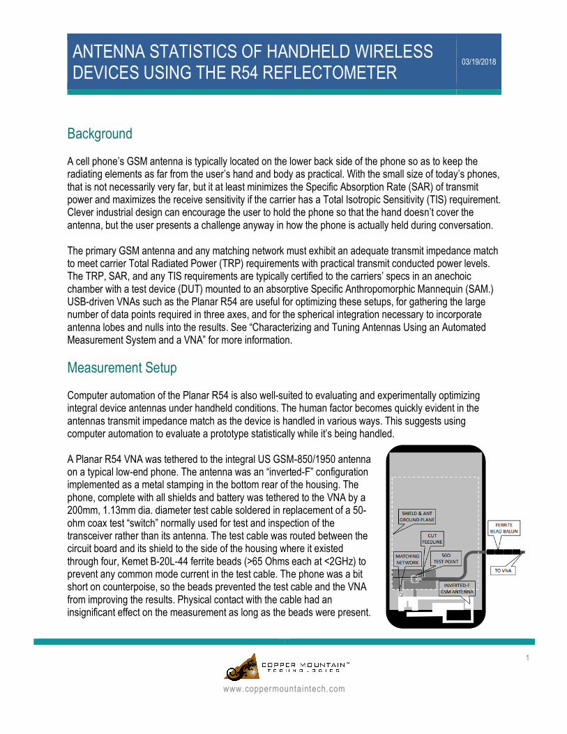
ANTENNA STATISTICS OF HANDHELD WIRELESS DEVICES USING THE R54 REFLECTOMETER 03/19/2018 1 www.coppermountaintech.com Background A cell phone’s GSM antenna is typically located on the lower back side of the phone so as to keep the radiating elements as far from the user’s hand and body as practical. With the small size of today’s phones, that is not necessarily very far, but it at least minimizes the Specific Absorption Rate (SAR) of transmit power and maximizes the receive sensitivity if the carrier has a Total Isotropic Sensitivity (TIS) requirement. Clever industrial design can encourage the user to hold the phone so that the hand doesn’t cover the antenna, but the user presents a challenge anyway in how the phone is actually held during conversation. The primary GSM antenna and any matching network must exhibit an adequate transmit impedance match to meet carrier Total Radiated Power (TRP) requirements with practical transmit conducted power levels. The TRP, SAR, and any TIS requirements are typically certified to the carriers’ specs in an anechoic chamber with a test device (DUT) mounted to an absorptive Specific Anthropomorphic Mannequin (SAM.) USB-driven VNAs such as the Planar R54 are useful for optimizing these setups, for gathering the large number of data points required in three axes, and for the spherical integration necessary to incorporate antenna lobes and nulls into the results. See “Characterizing and Tuning Antennas Using an Automated Measurement System and a VNA” for more information. Measurement Setup Computer automation of the Planar R54 is also well-suited to evaluating and experimentally optimizing integral device antennas under handheld conditions. The human factor becomes quickly evident in the antennas transmit impedance match as the device is handled in various ways. This suggests using computer automation to evaluate a prototype statistically while it’s being handled. A Planar R54 VNA was tethered to the integral US GSM-850/1950 antenna on a typical low-end phone. The antenna was an “inverted-F” configuration implemented as a metal stamping in the bottom rear of the housing. The phone, complete with all shields and battery was tethered to the VNA by a 200mm, 1.13mm dia. diameter test cable soldered in replacement of a 50- ohm coax test “switch” normally used for test and inspection of the transceiver rather than its antenna. The test cable was routed between the circuit board and its shield to the side of the housing where it existed through four, Kemet B-20L-44 ferrite beads (>65 Ohms each at <2GHz) to prevent any common mode current in the test cable. The phone was a bit short on counterpoise, so the beads prevented the test cable and the VNA from improving the results. Physical contact with the cable had an insignificant effect on the measurement as long as the beads were present.
Transcript of Antenna Statistics of Handheld Wireless Devices with R54 ...
ANTENNA STATISTICS OF HANDHELD WIRELESS DEVICES USING THE R54 REFLECTOMETER
03/19/2018
1
www.coppermountaintech.com
Background A cell phone’s GSM antenna is typically located on the lower back side of the phone so as to keep the radiating elements as far from the user’s hand and body as practical. With the small size of today’s phones, that is not necessarily very far, but it at least minimizes the Specific Absorption Rate (SAR) of transmit power and maximizes the receive sensitivity if the carrier has a Total Isotropic Sensitivity (TIS) requirement. Clever industrial design can encourage the user to hold the phone so that the hand doesn’t cover the antenna, but the user presents a challenge anyway in how the phone is actually held during conversation. The primary GSM antenna and any matching network must exhibit an adequate transmit impedance match to meet carrier Total Radiated Power (TRP) requirements with practical transmit conducted power levels. The TRP, SAR, and any TIS requirements are typically certified to the carriers’ specs in an anechoic chamber with a test device (DUT) mounted to an absorptive Specific Anthropomorphic Mannequin (SAM.) USB-driven VNAs such as the Planar R54 are useful for optimizing these setups, for gathering the large number of data points required in three axes, and for the spherical integration necessary to incorporate antenna lobes and nulls into the results. See “Characterizing and Tuning Antennas Using an Automated Measurement System and a VNA” for more information. Measurement Setup Computer automation of the Planar R54 is also well-suited to evaluating and experimentally optimizing integral device antennas under handheld conditions. The human factor becomes quickly evident in the antennas transmit impedance match as the device is handled in various ways. This suggests using computer automation to evaluate a prototype statistically while it’s being handled. A Planar R54 VNA was tethered to the integral US GSM-850/1950 antenna on a typical low-end phone. The antenna was an “inverted-F” configuration implemented as a metal stamping in the bottom rear of the housing. The phone, complete with all shields and battery was tethered to the VNA by a 200mm, 1.13mm dia. diameter test cable soldered in replacement of a 50-ohm coax test “switch” normally used for test and inspection of the transceiver rather than its antenna. The test cable was routed between the circuit board and its shield to the side of the housing where it existed through four, Kemet B-20L-44 ferrite beads (>65 Ohms each at <2GHz) to prevent any common mode current in the test cable. The phone was a bit short on counterpoise, so the beads prevented the test cable and the VNA from improving the results. Physical contact with the cable had an insignificant effect on the measurement as long as the beads were present.
ANTENNA STATISTICS OF HANDHELD WIRELESS DEVICES USING THE R54 REFLECTOMETER 03/19/2018
2
www.coppermountaintech.com
Measurements
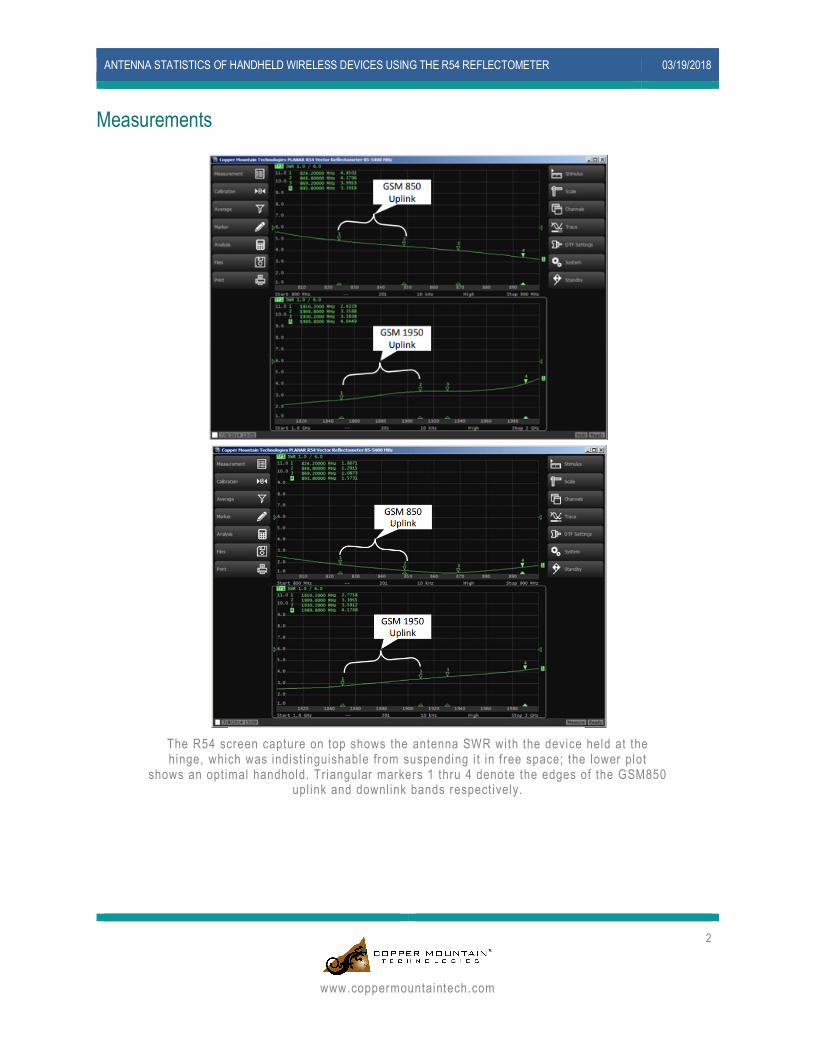
The R54 screen capture on top shows the antenna SWR with the device held at the hinge, which was indist inguishable from suspending i t in f ree space; the lower plot
shows an opt imal handhold. Tr iangular markers 1 thru 4 denote the edges of the GSM850 upl ink and downl ink bands respect ively.
ANTENNA STATISTICS OF HANDHELD WIRELESS DEVICES USING THE R54 REFLECTOMETER 03/19/2018
3
www.coppermountaintech.com
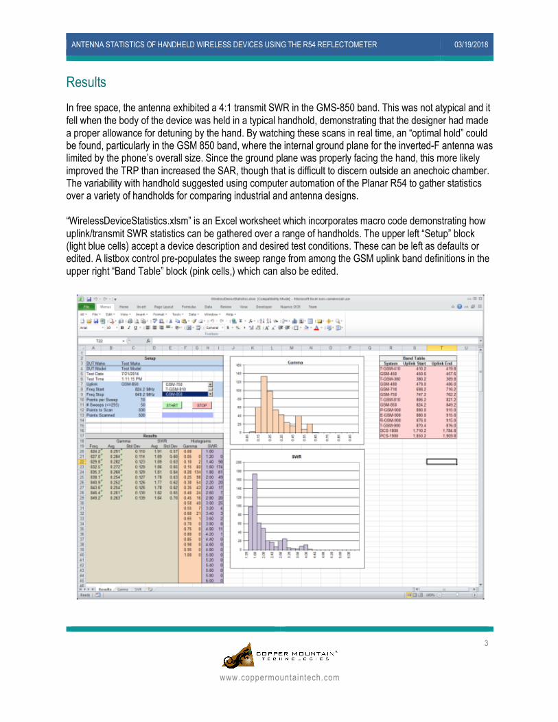
Results In free space, the antenna exhibited a 4:1 transmit SWR in the GMS-850 band. This was not atypical and it fell when the body of the device was held in a typical handhold, demonstrating that the designer had made a proper allowance for detuning by the hand. By watching these scans in real time, an “optimal hold” could be found, particularly in the GSM 850 band, where the internal ground plane for the inverted-F antenna was limited by the phone’s overall size. Since the ground plane was properly facing the hand, this more likely improved the TRP than increased the SAR, though that is difficult to discern outside an anechoic chamber. The variability with handhold suggested using computer automation of the Planar R54 to gather statistics over a variety of handholds for comparing industrial and antenna designs. “WirelessDeviceStatistics.xlsm” is an Excel worksheet which incorporates macro code demonstrating how uplink/transmit SWR statistics can be gathered over a range of handholds. The upper left “Setup” block (light blue cells) accept a device description and desired test conditions. These can be left as defaults or edited. A listbox control pre-populates the sweep range from among the GSM uplink band definitions in the upper right “Band Table” block (pink cells,) which can also be edited.
ANTENNA STATISTICS OF HANDHELD WIRELESS DEVICES USING THE R54 REFLECTOMETER 03/19/2018
4
www.coppermountaintech.com
If an R-54 is connected and the COM object was allowed to register as part of the R54 driver and application install, clicking the START control begins to gather 500 points across the selected frequency range. As data is gathered, the blue/gray bar chart shows the progress towards 500 points and the two histograms show data as it is gathered. The histograms are binned according to the values in cells F20:F40.. and H20:H45, which can also be edited if desired. Data collection stops when the desired number of points across the specified band have been entered or if the STOP control is clicked.
The VBA macro code in Sheet1 demonstrates the use of the R-54’s Standard Commands for Programmable Instruments (SCPI) interface to collect the data and VBA code to service the listbox and button controls. The statistical calculations (light brown cells) and the binning in the histograms are performed by ordinary cell formulas.
Saving the workbook as a macro-enabled workbook (.xslm) will save everything - the test conditions, time/date, results, graphs, and raw data. Saving it as a macro-free workbook (.xls) will strip the macro code and protect the data from be overwritten by an accidental click on the START control.
Conclusion The R54 can be used to characterize important quality parameters for cell phone antennas, and can be automated to populate an excel template with the measured data. The data can also be saved in a .s1p or .s2p file, graphs can be saved as images or directly posted to a word document, and calibration data can be saved in calibration files. In short, any measurement taken by the device can be exported in a desired file type. The R54 is a simple sweeping solution to all of the cell phone antenna test and verification applications, while replacing huge bulky VNA’s with something that can fit in the palm of your hand. Automation examples for the R54 and all of our other products can be found in the VNA folder, installed with the device software. You can obtain both the demo software, and the full software at http://www.coppermountaintech.com/ by clicking on products, Reflectometers, R54, and then clicking on the software link on the right side of the screen. Finally, if you have any issues with automating the R54, or any other device, feel free to email us at [email protected], or call us at +1.317.222.5400.