![Design of Wide Band Patch Antenna with DGS L StructureDesign parameters are calculated using the equations given by C. A. Balanis, Antenna Theory [1]. The essential parameters for](https://static.fdocuments.us/doc/165x107/5e893a7a13f46577fe591e30/design-of-wide-band-patch-antenna-with-dgs-l-structure-design-parameters-are-calculated.jpg)
Antenna Parameters - Lanka Education and Research...
49
Antenna Parameters Ranga Rodrigo University of Moratuwa December 15, 2008 Ranga Rodrigo (University of Moratuwa) Antenna Parameters December 15, 2008 1 / 47
Transcript of Antenna Parameters - Lanka Education and Research...

Antenna Parameters
Ranga Rodrigo
University of Moratuwa
December 15, 2008
Ranga Rodrigo (University of Moratuwa) Antenna Parameters December 15, 2008 1 / 47

Summary of Last Week’s Lecture
Radiation Pattern for an Array with 10 Elements
0o
45o
90o
135o
180o
225o
270o
315o
φ0.1 0.2 0.3 0.4 0.5 0.6 0.7 0.8 0.90.5 1
φHP
Figure 1: Half-Power Beam Width
Ranga Rodrigo (University of Moratuwa) Antenna Parameters December 15, 2008 2 / 47

Summary of Last Week’s Lecture Directivity
Directivity
We defined a parameter known as the directivityof the antenna, denoted by the symbol D, as theratio of the maximum power density radiated bythe antenna to the average power density.Thus the directivity of the Hertzian dipole isgiven by
D =[Pr]max
[Pr]av= 1.5 (1)
Ranga Rodrigo (University of Moratuwa) Antenna Parameters December 15, 2008 3 / 47

Summary of Last Week’s Lecture Directivity
D = 4π[f (θ, φ)]max∫ π
θ=0
∫ 2π
φ=0f (θ, φ) sinθdθdφ
(2)
Ranga Rodrigo (University of Moratuwa) Antenna Parameters December 15, 2008 4 / 47
Summary of Last Week’s Lecture Linear Antennas
:
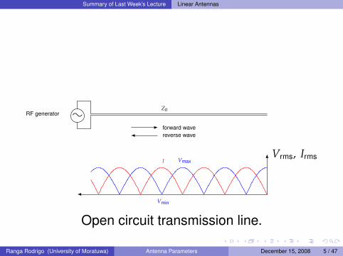
Vrms, IrmsVmax
Vmin
I
Z0RF generator
forward wavereverse wave
Open circuit transmission line.
Ranga Rodrigo (University of Moratuwa) Antenna Parameters December 15, 2008 5 / 47
Summary of Last Week’s Lecture Linear Antennas
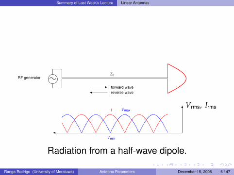
:
Vrms, IrmsVmax
Vmin
I
Z0RF generator
forward wavereverse wave
Radiation from a half-wave dipole.
Ranga Rodrigo (University of Moratuwa) Antenna Parameters December 15, 2008 6 / 47
Summary of Last Week’s Lecture Radiation Field Due to half-Wave Dipole
Now to find the radiation field due to the half-wavedipole, we divide it into a number of Hertzian dipoles,each of length dz′.
Ranga Rodrigo (University of Moratuwa) Antenna Parameters December 15, 2008 7 / 47

Summary of Last Week’s Lecture Radiation Field Due to half-Wave Dipole
y
x
z
P
L2
−L2
θ′
θ
r′
r
z′
dz′
iθ′
iφ′
z′ cosθ
Half-wave dipole as a number of Hertzian dipoles.
Ranga Rodrigo (University of Moratuwa) Antenna Parameters December 15, 2008 8 / 47

Summary of Last Week’s Lecture Field Equation for the Half-Wave Dipole
Evaluating the integral we obtain
Eθ = −ηI0
2πrcos [(π/2) cosθ]
sinθsin
(ωt −
πL
r). (3a)
SimilarlyH = Hφiφ.
where
Hφ = −I0
2πrcos [(π/2) cosθ]
sinθsin
(ωt −
πL
r). (3b)
Ranga Rodrigo (University of Moratuwa) Antenna Parameters December 15, 2008 9 / 47

Summary of Last Week’s Lecture Power Radiated for the Half-Wave Dipole
Power Radiated
Prad =0.609ηI2
0
πsin2
(ωt −
πL
r). (4)
Ranga Rodrigo (University of Moratuwa) Antenna Parameters December 15, 2008 10 / 47

Summary of Last Week’s Lecture Power Radiated for the Half-Wave Dipole
Time-Average Radiated Power
〈Prad〉 =12
I20
(0.609ηπ
). (5)
Ranga Rodrigo (University of Moratuwa) Antenna Parameters December 15, 2008 11 / 47
Summary of Last Week’s Lecture Power Radiated for the Half-Wave Dipole
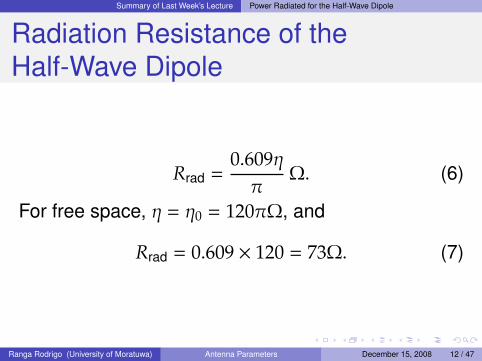
Radiation Resistance of theHalf-Wave Dipole
Rrad =0.609ηπ
Ω. (6)
For free space, η = η0 = 120πΩ, and
Rrad = 0.609 × 120 = 73Ω. (7)
Ranga Rodrigo (University of Moratuwa) Antenna Parameters December 15, 2008 12 / 47
Summary of Last Week’s Lecture Radiation Pattern
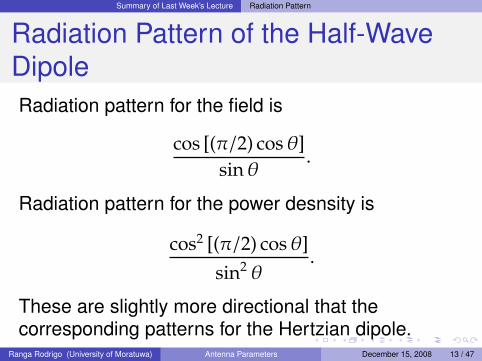
Radiation Pattern of the Half-WaveDipoleRadiation pattern for the field is
cos [(π/2) cosθ]sinθ
.
Radiation pattern for the power desnsity is
cos2 [(π/2) cosθ]sin2 θ
.
These are slightly more directional that thecorresponding patterns for the Hertzian dipole.
Ranga Rodrigo (University of Moratuwa) Antenna Parameters December 15, 2008 13 / 47

Summary of Last Week’s Lecture Radiation Pattern
Directivity of the Half-Wave Dipole
From 2D = 1.642.
Ranga Rodrigo (University of Moratuwa) Antenna Parameters December 15, 2008 14 / 47

Summary of Last Week’s Lecture Center-Fed Linear Antennas of Arbitrary Length
Center-Fed Linear Antennas ofArbitrary Length
Eθ = −ηI0
2πrF(θ) sin(ωt − βr). (8a)
Hφ = −I0
2πrF(θ) sin(ωt − βr). (8b)
Rrad =η
π
∫ π/2
θ=0F2(θ) sinθdθ. (8c)
D =
[F2(θ)
]max∫ π/2
θ=0F2(θ) sinθdθ
. (8d)
Ranga Rodrigo (University of Moratuwa) Antenna Parameters December 15, 2008 15 / 47
Summary of Last Week’s Lecture Center-Fed Linear Antennas of Arbitrary Length
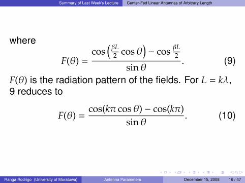
where
F(θ) =cos
(βL2 cosθ
)− cos βL
2
sinθ. (9)
F(θ) is the radiation pattern of the fields. For L = kλ,9 reduces to
F(θ) =cos(kπ cosθ) − cos(kπ)
sinθ. (10)
Ranga Rodrigo (University of Moratuwa) Antenna Parameters December 15, 2008 16 / 47

Antenna Parameters Directivity Continued
More on Directivity
We learned how to compute the directivitybased on the radiation pattern.Directivity has no units, and is usually given indB or dBi, where the reference directivity is 1,the directivity of an isotropic antenna.However, sometimes the reference directivity isthat of a half-wave dipole, 1.642. The directivitythen is in dBd.
Ranga Rodrigo (University of Moratuwa) Antenna Parameters December 15, 2008 17 / 47

Antenna Parameters Gain
Gain
The gain of a transmit antenna is proportional tothe directivity by a constant known as theantenna efficiency ot efficiency factor.This efficiency accounts for the power losseswithin the antenna.Gain, therefore, is not only a descriptor ofantenna’s power focusing ability, but also, takesinto account the power losses within theantenna.Therefore the gain is always less than thedirectivity.
Ranga Rodrigo (University of Moratuwa) Antenna Parameters December 15, 2008 18 / 47
Antenna Parameters Gain
Gain
Gain can be defined as
G =maximum radiation intensity
maximum radiation intensity from a ref-erence antenna with same power output
(11)
Ranga Rodrigo (University of Moratuwa) Antenna Parameters December 15, 2008 19 / 47

Antenna Parameters Gain
Gain
Often, the reference antenna is a linearhalf-wave antenna.If the reference antenna is assumed to be anisotropic antenna with 100 percent efficiency,the gain so defined for the subject antenna iscalled the gain with respect to an isotropicsource and is designated G0.
G0 =
maximum radiation intensity fromsubject antenna
radiation intensity from (lossless)isotropic source with same power input
(12)
Ranga Rodrigo (University of Moratuwa) Antenna Parameters December 15, 2008 20 / 47
Antenna Parameters Gain
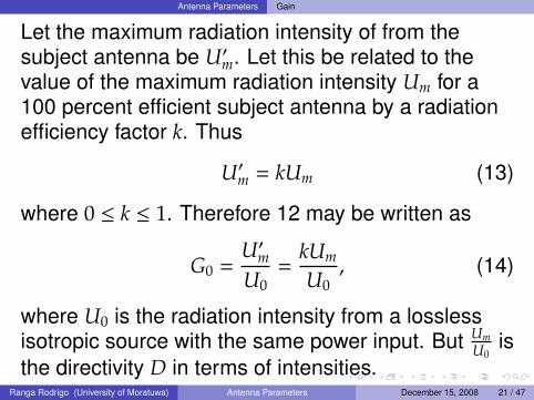
Let the maximum radiation intensity of from thesubject antenna be U′m. Let this be related to thevalue of the maximum radiation intensity Um for a100 percent efficient subject antenna by a radiationefficiency factor k. Thus
U′m = kUm (13)
where 0 ≤ k ≤ 1. Therefore 12 may be written as
G0 =U′mU0
=kUm
U0, (14)
where U0 is the radiation intensity from a losslessisotropic source with the same power input. But Um
U0is
the directivity D in terms of intensities.Ranga Rodrigo (University of Moratuwa) Antenna Parameters December 15, 2008 21 / 47

Antenna Parameters Gain
Gain
G = kD (15)
where k is the efficiency factor.
Ranga Rodrigo (University of Moratuwa) Antenna Parameters December 15, 2008 22 / 47

Antenna Parameters Gain
Why Is Gain Always Less ThanDirectivity For a Practical Antenna?
The gain of a transmit antenna is proportional todirectivity by a constant known as the antennaefficiency. This efficiency accounts for the powerlosses within the antenna. Gain therefore is not onlya descriptor of the antenna’s power focusing abilitybut also takes into account power losses within theantenna. Therefore, gain is always less than thedirectivity.
Ranga Rodrigo (University of Moratuwa) Antenna Parameters December 15, 2008 23 / 47

Antenna Parameters Efficiency
Efficiency
1 If the efficiency of an antenna is 100%, all thepower delivered to the antenna is radiated.
2 Usually, however, some of this power is lost inconduction and dielectic losses.
3 Therefore, the efficiency is typically less than100%.
4 A useful antenna should have an efficiency thatis in the very least in the 80% range.
Ranga Rodrigo (University of Moratuwa) Antenna Parameters December 15, 2008 24 / 47

Antenna Parameters Efficiency
Efficiency
Pout = I2Rrad. (16)
Pin = I2(Rrad + Rloss). (17)
where Rloss is the loss resistance.
Efficiency =Pout
Pin=
Rrad
Rrad + Rloss. (18)
Ranga Rodrigo (University of Moratuwa) Antenna Parameters December 15, 2008 25 / 47
Antenna Parameters Antenna Aperture
The Aperture Concept
Consider a horn antenna as a receiving antenna.The power absorbed by the antenna is SA where Ais the aperture area and S is the magnitude of powerdensity of the incident electromagnetic wave.
Ranga Rodrigo (University of Moratuwa) Antenna Parameters December 15, 2008 26 / 47
Antenna Parameters Antenna Aperture
Effective Area of an ApertureAn antenna has an effective aperture area as areceive antenna; it is the area which extracts thepower from the incident electromagnetic wave.As a transmit antenna, the effective area is thearea from which electromagnetic waves aregiven out.For aperture antennas such as horn antennas,the effective area is closely related to thephysical area.However, for wire antennas such as dipoles, theeffective area is much bigger than the physicalarea of the antenna.
Ranga Rodrigo (University of Moratuwa) Antenna Parameters December 15, 2008 27 / 47
Antenna Parameters Antenna Aperture
Effective Aperture
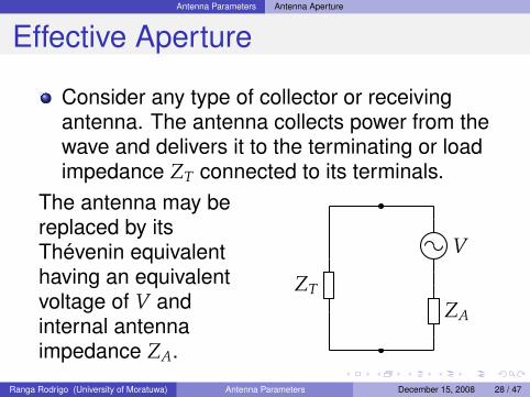
Consider any type of collector or receivingantenna. The antenna collects power from thewave and delivers it to the terminating or loadimpedance ZT connected to its terminals.
The antenna may bereplaced by itsThevenin equivalenthaving an equivalentvoltage of V andinternal antennaimpedance ZA.
ZA
V
ZT
Ranga Rodrigo (University of Moratuwa) Antenna Parameters December 15, 2008 28 / 47
Antenna Parameters Antenna Aperture
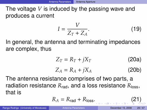
The voltage V is induced by the passing wave andproduces a current
I =V
ZT + ZA. (19)
In general, the antenna and terminating impedancesare complex, thus
ZT = RT + jXT (20a)
ZA = RA + jXA (20b)The antenna resistance comprises of two parts, aradiation resistance Rrad, and a loss resistance Rloss,that is
RA = Rrad + Rloss. (21)Ranga Rodrigo (University of Moratuwa) Antenna Parameters December 15, 2008 29 / 47

Antenna Parameters Antenna Aperture
Let the power delivered by the antenna to theterminating impedance be W. Then
W = I2RT (22)
I =V√
(Rrad + Rloss + RT)2 + (XA + XT)2. (23)
W =V2RT
(Rrad + Rloss + RT)2 + (XA + XT)2 . (24)
Ranga Rodrigo (University of Moratuwa) Antenna Parameters December 15, 2008 30 / 47

Antenna Parameters Antenna Aperture
Effective ApertureThe ratio of power W in the terminating impedanceto the power density of the incident wave will bedefined as the effective aperture Ae. Thus,
Effective aperture =WP
= Ae, (25)
where P = |P|. Thus,
Ae =V2RT
P[(Rrad + Rloss + RT)2 + (XA + XT)2
] . (26)
V is the induced voltage when the antenna isoriented for maximum response and the incidentwave has the same polarization as the antenna.
Ranga Rodrigo (University of Moratuwa) Antenna Parameters December 15, 2008 31 / 47

Antenna Parameters Maximum Effective Aperture
Maximum Effective ApertureWhen the terminating impedance is the complexconjugate of the antenna impedance, so that themaximum power is transferred, and if the antennalosses are zero (Rloss = 0 and therefore RA = Rrad),
XT = −XA (27)
RT = Rrad. (28)
So, the largest possible power is
W′ =V2RT
4R2T
=V2
4Rrad. (29)
Ranga Rodrigo (University of Moratuwa) Antenna Parameters December 15, 2008 32 / 47

Antenna Parameters Maximum Effective Aperture
The power W′ is delivered to the terminatingimpedance under the conditions of maximumpower transfer and zero antenna losses.The ration of this power to the power density ofthe incident wave is the maximum effectiveaperture Aem.
Maximum effective aperture =W′
P= Aem. (30)
Aem =V2
4PRrad. (31)
Ranga Rodrigo (University of Moratuwa) Antenna Parameters December 15, 2008 33 / 47

Antenna Parameters Maximum Effective Aperture of a Hertzian Dipole
Maximum Effective Aperture of aHertzian DipoleConsider the Hertzian dipole with length dl λ, witha uniform current distribution. The terminatingresistance RT is assumed to be equal to Rrad, andthe antenna loss resistance Rloss is assumed to beequal to zero.
V = Edl. (32)
We found that
Rrad = 80π2
(dlλ
)2
Ω (33)
Ranga Rodrigo (University of Moratuwa) Antenna Parameters December 15, 2008 34 / 47

Antenna Parameters Maximum Effective Aperture of a Hertzian Dipole
The (magnitude) of the power density in free space is
P =E2
η=
E2
120π(34)
The maximum effective aperture of the Hertziandipole is
Aem =120πE2(dl)2λ2
320π2E2(dl)2 =3λ2
8π= 0.119λ2. (35)
Ranga Rodrigo (University of Moratuwa) Antenna Parameters December 15, 2008 35 / 47

Antenna Parameters Maximum Effective Aperture of a Half-Wave Dipole
Maximum Effective Aperture of aHalf-Wave Dipole
y
x
z
P
L2
−L2
θ′
θ
r′
r
z′
dz′
iθ′
iφ′
z′ cosθ
Half-wave dipole as a number of Hertzian dipoles.
Ranga Rodrigo (University of Moratuwa) Antenna Parameters December 15, 2008 36 / 47

Antenna Parameters Maximum Effective Aperture of a Half-Wave Dipole
Maximum Effective Aperture of aHalf-Wave DipoleWe noticed that when we considered the Hertziandipole at a distance z′ from the origin of a half-wavedipole, the current in this Hertzian dipole isI0 cos(πz′/L) cosωt. For the half-wave dipole L = λ/2.The infinitesimal voltage dV due to the voltageinduced by the incident wave is this Hertzian dipoleof length dz′ is
dV = E(dz′) cos(2πz′/λ) (36)
We can find the total induced voltage by integratingover z′.
Ranga Rodrigo (University of Moratuwa) Antenna Parameters December 15, 2008 37 / 47

Antenna Parameters Maximum Effective Aperture of a Half-Wave Dipole
Radiator Aem D D (dB)
Isotropicλ2
4π1 0
Short dipole1 3λ2
8π1.5 1.76
Half-wave dipole30λ2
73π1.64 2.14
1A short dipole is always of finite length even though it may be veryshort. The current along a short dipole is uniform.
Ranga Rodrigo (University of Moratuwa) Antenna Parameters December 15, 2008 38 / 47
Received Power in a Communication System
Received Power in a CommunicationSystem
The received power in relation to a radio link isgiven by the Friis transmission formula, whichwas presented by harold T. Friis while at BellLabs in 1946.
Ranga Rodrigo (University of Moratuwa) Antenna Parameters December 15, 2008 39 / 47

Received Power in a Communication System
Suppose the transmit antenna and the receiveantenna are aligned for maximum reception.If the transmit antenna is isotropic, the powerdensity of the electromagnetic wave at thereceiver is
Sr =Pt
4πR2 (37)
where Pt is the transmit power, and R is thedistance from the transmitter.However, if the transmitter has a gain Gt, thepower density at the receiver is
Sr =PtGt
4πR2 (38)
Ranga Rodrigo (University of Moratuwa) Antenna Parameters December 15, 2008 40 / 47
Received Power in a Communication System
If the effective area of the receive antenna is Aer,the power collected at the receiver, Pr = SrAer, is
Pr =PtGtAer
4πR2 . (39)
Directivity and gain are related to the aperturearea. Thus, the gain of the transmitter Gt isrelated to its aperture Aet by
Gt =4πλ2 Aet. (40)
Therefore, from Equations 39 and 40 we get
Pr =PtAetAer
R2λ2 . (41)
Ranga Rodrigo (University of Moratuwa) Antenna Parameters December 15, 2008 41 / 47

Received Power in a Communication System
Power given by Equation 41 can also beexpressed in terms of antenna gains:
Pr = PtGtGr
(λ
4πR
)2
. (42)
Ranga Rodrigo (University of Moratuwa) Antenna Parameters December 15, 2008 42 / 47
Received Power in a Communication System
Example 3.1What is the maximum effective aperture of amicrowave antenna with a directivity of 800?Assume that the antenna is designed for 10 GHz.
Solution 3.2
D =4πλ2 Aem.
λ = 3 cm = .03 m.
Aem = 800.032
4π= 0.057 m2.
Ranga Rodrigo (University of Moratuwa) Antenna Parameters December 15, 2008 43 / 47

Received Power in a Communication System
Example 3.3What is the maximum power received at a distanceof 2 km over a 7 GHz free-space link consisting of atransmit antenna with a 30 dB gain and a receiveantenna with a 25 dB gain? The gains areexpressed with respect to a lossless isotropicsource. The transmit antenna input power is 1 kW.
Ranga Rodrigo (University of Moratuwa) Antenna Parameters December 15, 2008 44 / 47

Received Power in a Communication System
Solution 3.4
Pr = PtGtGr
(λ
4πR
)2
,
Pr (dBW) = Pt (dBW) + Gt (dB) + Gr (dB) + 10 log(λ
4πR
)2
,
= 30 + 30 + 25 − 97.7,= −12.7 (dB) ,= 0.2 pW .
Ranga Rodrigo (University of Moratuwa) Antenna Parameters December 15, 2008 45 / 47

Variation of Directivity with Length
Variation of Directivity with Length
As the length of the antenna becomes longer,the antenna beamwidth becomes narrower.However, as the antenna becomes longer that awavelength, side-lobes appear in the radiationpattern.This means that the radiation is now not focusedin one main-lobe but is focused in multipledirections.
Ranga Rodrigo (University of Moratuwa) Antenna Parameters December 15, 2008 46 / 47

Variation of Directivity with Length
Reference
Indra J. Dayawansa.Antennas and propagation.Lecture notes, University of Moratuwa, 2003.
John D. Kraus.Antennas.McGraw-Hill, 1950.
Nannapaneni Narayana Rao.Elements of Engineering Electromaganetics.Prentice Hall, 4th edition, 1994.
Ranga Rodrigo (University of Moratuwa) Antenna Parameters December 15, 2008 47 / 47


![01 - Antenna Parameters[1]](https://static.fdocuments.us/doc/165x107/577d1f271a28ab4e1e8ffcd3/01-antenna-parameters1.jpg)