Antenna - Cisco · Base Range Extender—Pole Mounted Antenna Configuration Table 4-5 Pole Mounted...
16
CHAPTER 4-1 Cisco IR500 Series WPAN Gateway and WPAN Range Extender Installation and Configuration Guide 4 Antenna This chapter contains information about the antennas for the Cisco Industrial Routers (IR500) Series WPAN Gateway and WPAN Range Extender devices. The antennas provide connectivity to the CG-Mesh. This chapter contains the following sections: • Antennas Overview, page 4-1 • Installing or Replacing Antennas, page 4-15 Antennas Overview • WPAN Gateway Antenna Configurations, page 4-1 • WPAN Range Extender Antenna Configurations, page 4-8 WPAN Gateway Antenna Configurations • Gateway Pole Mounted Antenna with Below Grade Conduit Routed Cabling Configuration, page 4-2 • Gateway Enclosure Mounted Antenna Configuration, page 4-4 • Gateway Pole Mounted Antenna with Enclosure Interface Lightning Arrestor Configuration, page 4-6
Transcript of Antenna - Cisco · Base Range Extender—Pole Mounted Antenna Configuration Table 4-5 Pole Mounted...
Cisco IR500 Series WPAN Gateway and WPAN R
C H A P T E R 4
AntennaThis chapter contains information about the antennas for the Cisco Industrial Routers (IR500) Series WPAN Gateway and WPAN Range Extender devices. The antennas provide connectivity to the CG-Mesh.
This chapter contains the following sections:
• Antennas Overview, page 4-1
• Installing or Replacing Antennas, page 4-15
Antennas Overview• WPAN Gateway Antenna Configurations, page 4-1
• WPAN Range Extender Antenna Configurations, page 4-8
WPAN Gateway Antenna Configurations• Gateway Pole Mounted Antenna with Below Grade Conduit Routed Cabling Configuration,
page 4-2
• Gateway Enclosure Mounted Antenna Configuration, page 4-4
• Gateway Pole Mounted Antenna with Enclosure Interface Lightning Arrestor Configuration, page 4-6
4-1ange Extender Installation and Configuration Guide

Chapter 4 AntennaAntennas Overview
Gateway Pole Mounted Antenna with Below Grade Conduit Routed Cabling Configuration
Table 4-1 lists the antenna, cables and connectors in the antenna configuration, and Figure 4-1 shows the setup of the antenna.
Table 4-1 Pole Mounted Antenna with Below Grade Conduit Routed Cabling Configuration for the IR509UWP-915/K9
Gateway
Antenna Arrangement and Gateway Connector
Enclosure Internal Cable Lightning Arrestor or Adapter
Outdoor Cable Antenna
Pole mounted antenna, single antenna cable routed through below grade conduit, 1 QMA (f) gateway antenna connector
Select one cable from:
• 1 RA-QMA (m) to N (m) cable, LMR-240-FR, 10’, Cisco PID1 CAB-L240-10-Q-N, Cisco PN2 37-1351-02
• 1 RA-QMA (m) to N (m) cable, LMR-240-FR, 15’, Cisco PID CAB-L240-15-Q-N, Cisco part number 37-1352-02
• 1 RA-QMA (m) to N (m) cable, LMR-240-FR, 20’, Cisco PID CAB-L240-20-Q-N, Cisco PN 37-1353-02
1. PID = Product Identifier
2. PN = Part number
— A single cable routed from inside the enclosure to outside the enclosure
1 900 MHz ISM band, omni stick, 24”, 5 dBi, N (f), Cisco PID ANT-WPAN-OM-OUT-N, Cisco PN 07-1163-01
4-2Cisco IR500 Series WPAN Gateway and WPAN Range Extender Installation and Configuration Guide
Chapter 4 AntennaAntennas Overview
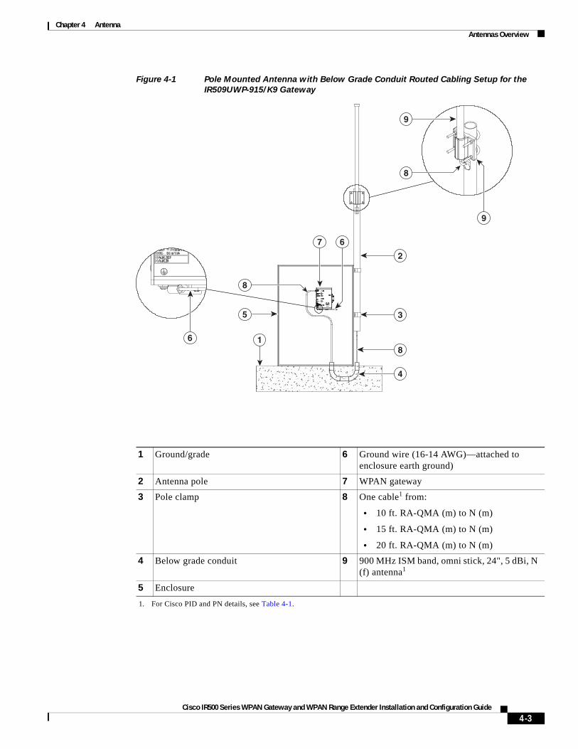
Figure 4-1 Pole Mounted Antenna with Below Grade Conduit Routed Cabling Setup for the
IR509UWP-915/K9 Gateway
1 Ground/grade 6 Ground wire (16-14 AWG)—attached to enclosure earth ground)
2 Antenna pole 7 WPAN gateway
3 Pole clamp 8 One cable1 from:
• 10 ft. RA-QMA (m) to N (m)
• 15 ft. RA-QMA (m) to N (m)
• 20 ft. RA-QMA (m) to N (m)
1. For Cisco PID and PN details, see Table 4-1.
4 Below grade conduit 9 900 MHz ISM band, omni stick, 24", 5 dBi, N (f) antenna1
5 Enclosure
6 1
5
8
7 6
2
9
8
9
3
8
4
4-3Cisco IR500 Series WPAN Gateway and WPAN Range Extender Installation and Configuration Guide

Chapter 4 AntennaAntennas Overview
Gateway Enclosure Mounted Antenna Configuration
Table 4-2 Enclosure Mounted Antenna Configuration for the IR509UWP-915/K9 Gateway
Antenna Arrangement and Gateway Connector
Enclosure Internal Cable Lightning Arrestor or Adapter
Outdoor Cable Antenna
Antenna directly mounted to lightning arrestor at enclosure interface to exterior, 1 QMA (f) gateway antenna connector
Select one cable from:
• 1 RA-QMA (m) to N(m) cable, LMR-240-FR, 10’, Cisco Product Identifier (PID) CAB-L240-10-Q-N, Cisco PN 37-1351-02
• 1 RA-QMA (m) to N(m) cable, LMR-240-FR, 15’, Cisco PID CAB-L240-15-Q-N, Cisco PN 37-1352-02
• 1 RA-QMA (m) to N(m) cable, LMR-240-FR, 20’, Cisco PID CAB-L240-20-Q-N, Cisco PN 37-1353-02
1 lightning arrestor, N (f)-N (f), Cisco PID CGR-LA-NF-NF, Cisco PN 07-1158-02
— 1 900 MHz ISM band, omni stick, 8”, 1.5 dBi, N (f), Cisco PID ANT-WPAN-OD-OUT-N, Cisco PN 07-1318-01
4-4Cisco IR500 Series WPAN Gateway and WPAN Range Extender Installation and Configuration Guide
Chapter 4 AntennaAntennas Overview
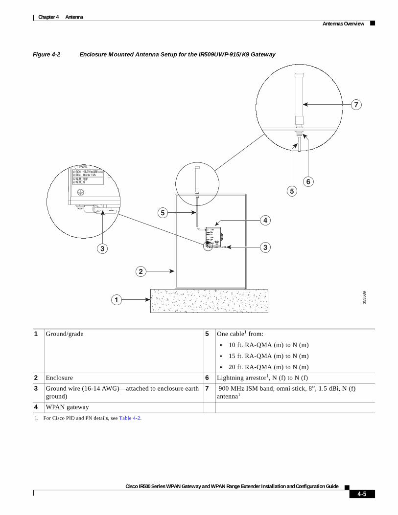
Figure 4-2 Enclosure Mounted Antenna Setup for the IR509UWP-915/K9 Gateway
1 Ground/grade 5 One cable1 from:
• 10 ft. RA-QMA (m) to N (m)
• 15 ft. RA-QMA (m) to N (m)
• 20 ft. RA-QMA (m) to N (m)
1. For Cisco PID and PN details, see Table 4-2.
2 Enclosure 6 Lightning arrestor1, N (f) to N (f)
3 Ground wire (16-14 AWG)—attached to enclosure earth ground)
7 900 MHz ISM band, omni stick, 8”, 1.5 dBi, N (f) antenna1
4 WPAN gateway
3535
89
1
2
5
7
3
4
3
65
4-5Cisco IR500 Series WPAN Gateway and WPAN Range Extender Installation and Configuration Guide

Chapter 4 AntennaAntennas Overview
Gateway Pole Mounted Antenna with Enclosure Interface Lightning Arrestor Configuration
Table 4-3 Pole Mounted Antenna with Enclosure Interface Lightning Arrestor Configuration for the IR509UWP-915/K9
Gateway
Antenna Arrangement and Gateway Connector
Enclosure Internal Cable Lightning Arrestor or Adapter
Outdoor Cable Antenna
Pole mounted antenna, lightning arrestor at enclosure interface to exterior, antenna exterior and internal cables used, 1 QMA (f) gateway antenna connector
Select one cable from:
• 1 RA-QMA (m) to N(m) cable, LMR-240-FR, 10’, Cisco Product Identifier (PID) CAB-L240-10-Q-N, Cisco PN 37-1351-02
• 1 RA-QMA (m) to N(m) cable, LMR-240-FR, 15’, Cisco PID CAB-L240-15-Q-N, Cisco PN 37-1352-02
• 1 RA-QMA (m) to N(m) cable, LMR-240-FR, 20’, Cisco PID CAB-L240-20-Q-N, Cisco PN 37-1353-02
1 lightning arrestor, N (f)-N (f), Cisco PID CGR-LA-NF-NF, Cisco PN 07-1158-02
Select one option from:
• 1 RA-N(m) to N(m) cable, LMR-400-DB, 5’, Cisco PID CAB-L400-5-N-N, Cisco PN 37-1436-01
• 1 N(m) to N(m) cable, LMR-400-DB, 5’, Cisco PID CAB-L400-5-N-NS, Cisco PN 37-1446-01
• 1 RA-N(m) to N(m) cables, LMR-400-DB, 20’, Cisco PID CAB-L400-20-N-N, Cisco PN 37-1392-01
• 1 RA-N(m)-N(m) cables, LMR-600-DB, 30’, Cisco PID CAB-L600-30-N-N, Cisco PN 37-1396-01
1 900 MHz ISM band, omni stick, 24”, 5 dBi, N (f), Cisco PID ANT-WPAN-OM-OUT-N, Cisco PN 07-1163-01
4-6Cisco IR500 Series WPAN Gateway and WPAN Range Extender Installation and Configuration Guide
Chapter 4 AntennaAntennas Overview
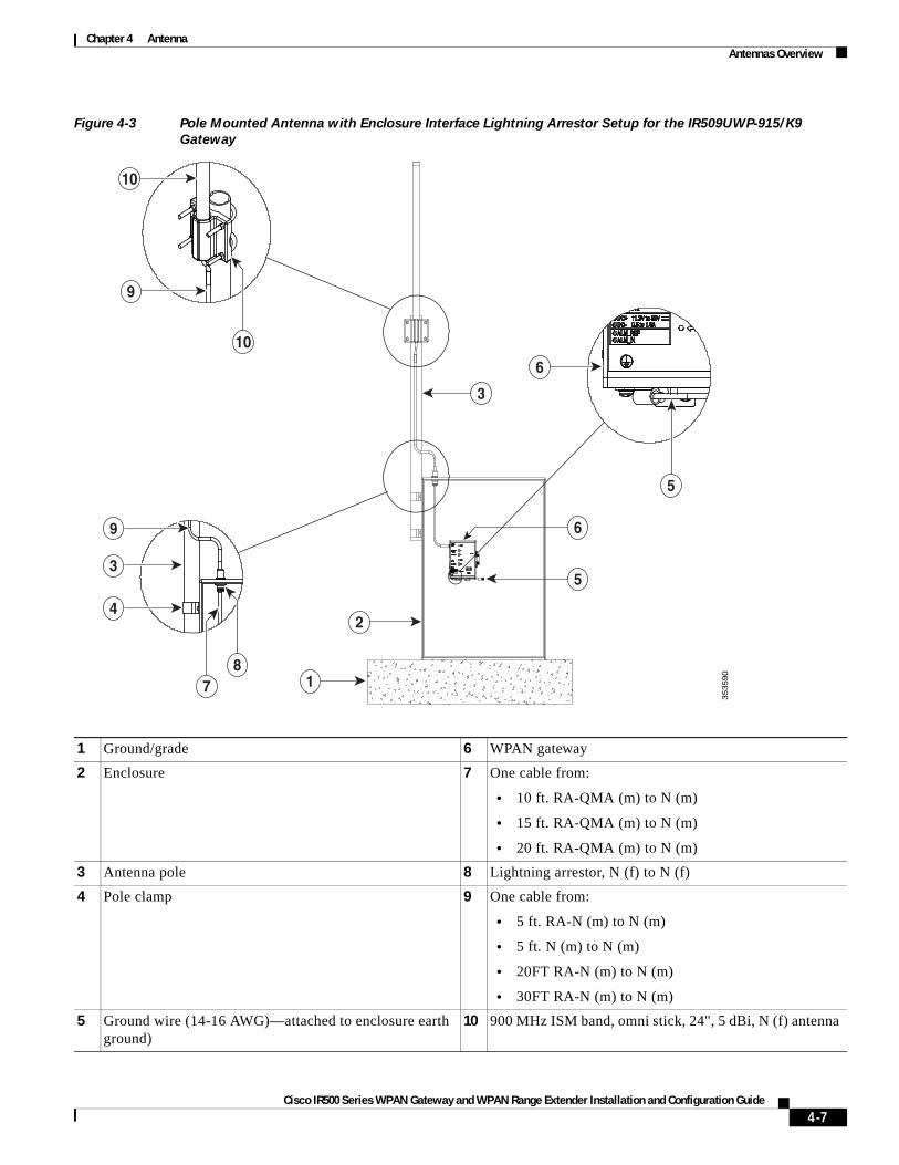
Figure 4-3 Pole Mounted Antenna with Enclosure Interface Lightning Arrestor Setup for the IR509UWP-915/K9
Gateway
1 Ground/grade 6 WPAN gateway
2 Enclosure 7 One cable from:
• 10 ft. RA-QMA (m) to N (m)
• 15 ft. RA-QMA (m) to N (m)
• 20 ft. RA-QMA (m) to N (m)
3 Antenna pole 8 Lightning arrestor, N (f) to N (f)
4 Pole clamp 9 One cable from:
• 5 ft. RA-N (m) to N (m)
• 5 ft. N (m) to N (m)
• 20FT RA-N (m) to N (m)
• 30FT RA-N (m) to N (m)
5 Ground wire (14-16 AWG)—attached to enclosure earth ground)
10 900 MHz ISM band, omni stick, 24", 5 dBi, N (f) antenna
35
35
90
1
2
5
3
6
4
3
9
9
6
10
8
10
7
5
4-7Cisco IR500 Series WPAN Gateway and WPAN Range Extender Installation and Configuration Guide
Chapter 4 AntennaAntennas Overview
WPAN Range Extender Antenna Configurations• Base Range Extender—Direct Connect Antenna Configuration, page 4-8
• Base Range Extender—Pole Mounted Antenna Configuration, page 4-9
• Single Antenna Advanced Range Extender—Direct Connect Antenna Configuration, page 4-10
• Single Antenna Advanced Range Extender—Pole Mounted Antenna Configuration, page 4-11
• Dual Antenna Advanced Range Extender—Dual Antenna Configuration, page 4-13
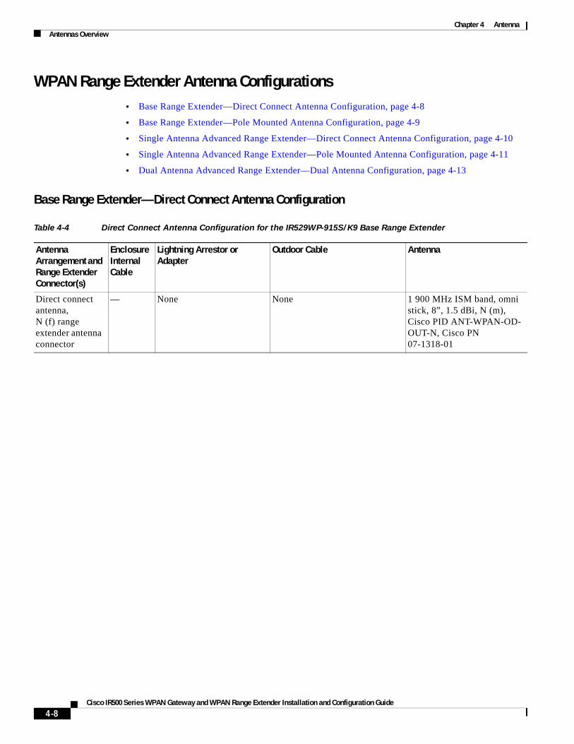
Base Range Extender—Direct Connect Antenna Configuration
Table 4-4 Direct Connect Antenna Configuration for the IR529WP-915S/K9 Base Range Extender
Antenna Arrangement and Range Extender Connector(s)
Enclosure Internal Cable
Lightning Arrestor or Adapter
Outdoor Cable Antenna
Direct connect antenna,N (f) range extender antenna connector
— None None 1 900 MHz ISM band, omni stick, 8”, 1.5 dBi, N (m), Cisco PID ANT-WPAN-OD-OUT-N, Cisco PN 07-1318-01
4-8Cisco IR500 Series WPAN Gateway and WPAN Range Extender Installation and Configuration Guide

Chapter 4 AntennaAntennas Overview
Base Range Extender—Pole Mounted Antenna Configuration
Table 4-5 Pole Mounted Antenna Configuration for the IR529WP-915S/K9 Base Range Extender
Antenna Arrangement and Range Extender Connector(s)
Enclosure Internal Cable
Lightning Arrestor or Adapter
Outdoor Cable Antenna
Pole mounted antenna, N (f) range extender antenna connector
— 1 Lightning Arrestor, DC Pass, N (m)-N (f), Cisco PID CGR-LA-NM-NF, Cisco PN 07-1091-02
Select one option from:
• 1 RA-N (m) to N (m) cable, LMR-400-DB, 5’, Cisco PID CAB-L400-5-N-N, Cisco PN 37-1436-01
• 1 N(m) to N(m) cable, LMR-400-DB, 5’, Cisco PID CAB-L400-5-N-NS, Cisco PN 37-1446-01
• 1 RA-N(m) to N(m) cables, LMR-400-DB, 20’, Cisco PID CAB-L400-20-N-N, Cisco PN 37-1392-01
• 1 RA-N(m)-N(m) cables, LMR-600-DB, 30’, Cisco PID CAB-L600-30-N-N, Cisco PN 37-1396-01
1 900 MHz ISM band, omni stick, 24”, 5 dBi, N (f), Cisco PID ANT-WPAN-OM-OUT-N, Cisco PN 07-1163-01
4-9Cisco IR500 Series WPAN Gateway and WPAN Range Extender Installation and Configuration Guide

Chapter 4 AntennaAntennas Overview
Single Antenna Advanced Range Extender—Direct Connect Antenna Configuration
Figure 4-4 Direct Connect Antenna Setup for the IR529UBWP-915S/K9 Single Antenna Advanced Range Extender
Table 4-6 Direct Connect Antenna Configuration for the IR529UBWP-915S/K9 Single Antenna Advanced Range
Extender
Antenna Arrangement and Range Extender Connector(s)
Enclosure Internal Cable
Lightning Arrestor or Adapter
Outdoor Cable Antenna
Direct connect single antenna,1 N (f) range extender antenna connector
— None None 1 900 MHz ISM band, omni stick, 8”, 1.5 dBi, N(m), Cisco PID ANT-WPAN-OD-OUT-N, Cisco PN 07-1318-01
1 Antenna pole 4 Single antenna advanced WPAN range extender1
1. IR529UBWP-915S/K9 model
2 Ground wire (4 to 6AWG) 5 900 MHz ISM band, omni stick, 8", 1.5 dBi, N (f) antenna2
2. For Cisco PID and PN details, see Table 4-6.
3 Ground pipe clamp 6 AC power chord
35
35
913
5 2
6
4
4
6
1
4-10Cisco IR500 Series WPAN Gateway and WPAN Range Extender Installation and Configuration Guide
Chapter 4 AntennaAntennas Overview
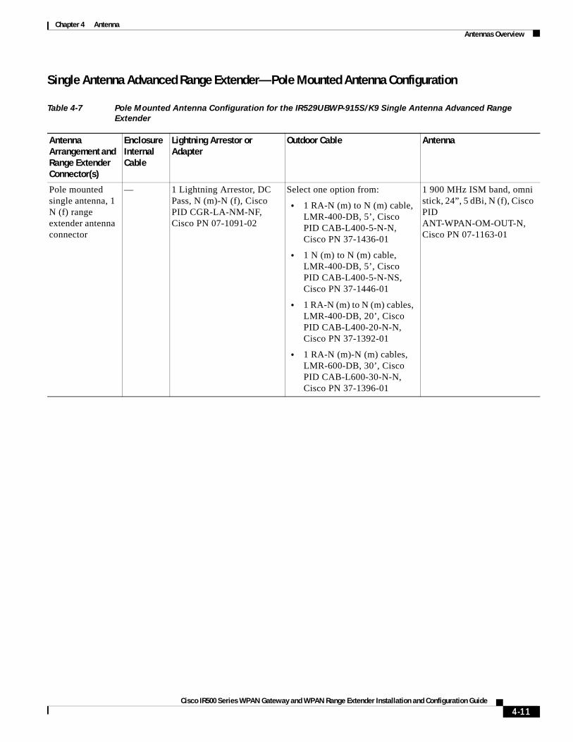
Single Antenna Advanced Range Extender—Pole Mounted Antenna Configuration
Table 4-7 Pole Mounted Antenna Configuration for the IR529UBWP-915S/K9 Single Antenna Advanced Range
Extender
Antenna Arrangement and Range Extender Connector(s)
Enclosure Internal Cable
Lightning Arrestor or Adapter
Outdoor Cable Antenna
Pole mounted single antenna, 1 N (f) range extender antenna connector
— 1 Lightning Arrestor, DC Pass, N (m)-N (f), Cisco PID CGR-LA-NM-NF, Cisco PN 07-1091-02
Select one option from:
• 1 RA-N (m) to N (m) cable, LMR-400-DB, 5’, Cisco PID CAB-L400-5-N-N, Cisco PN 37-1436-01
• 1 N (m) to N (m) cable, LMR-400-DB, 5’, Cisco PID CAB-L400-5-N-NS, Cisco PN 37-1446-01
• 1 RA-N (m) to N (m) cables, LMR-400-DB, 20’, Cisco PID CAB-L400-20-N-N, Cisco PN 37-1392-01
• 1 RA-N (m)-N (m) cables, LMR-600-DB, 30’, Cisco PID CAB-L600-30-N-N, Cisco PN 37-1396-01
1 900 MHz ISM band, omni stick, 24”, 5 dBi, N (f), Cisco PID ANT-WPAN-OM-OUT-N, Cisco PN 07-1163-01
4-11Cisco IR500 Series WPAN Gateway and WPAN Range Extender Installation and Configuration Guide

Chapter 4 AntennaAntennas Overview
Figure 4-5 Pole Mounted Antenna Setup for the IR529UBWP-915S/K9 Single Antenna Advanced Range Extender
1 Antenna pole 5 Lightning arrestor1, N (m) to N (f)
1. For Cisco PID and PN details, see Table 4-7.
2 Ground wire (4 to 6 AWG) 6 One cable1 from:
• 5 ft. RA-N (m) to N (m)
• 5 ft. N (m) to N (m)
• 20 ft. RA-N (m) to N (m)
• 30 ft. RA-N (m) to N (m)
3 Ground pipe clamp 7 900 MHz ISM band, omni stick, 24", 5 dBi, N (f) antenna1
4 Single antenna advanced WPAN range extender2
2. IR529UBWP-915S/K9 model
8 AC power chord
3535
92
6
6
7
5
2
3
1
8
4
4
4
7
7
8
4-12Cisco IR500 Series WPAN Gateway and WPAN Range Extender Installation and Configuration Guide

Chapter 4 AntennaAntennas Overview
Dual Antenna Advanced Range Extender—Dual Antenna Configuration
Note The dual antenna configuration applies to the dual antenna advanced range extender models with and without battery support:- IR529UBWP-915D/K9 (with battery support- IR529UWP-915D/K9 (without battery support)
Table 4-8 Dual Antenna Configuration for the IR529UBWP-915D/K9 and IR529UWP-915D/K9 Dual Antenna Advanced
Range Extenders
Antenna Arrangement and Connector(s)
Enclosure Internal Cable
Lightning Arrestor or Adapter
Outdoor Cable Antenna
Dual antenna,2 N (f) antenna connectors
— 2 Lightning Arrestors, N (m)-N (f), Cisco PID CGR-LA-NM-NF, Cisco PN 07-1091-02
Select one option:
• 2 RA-N (m) to N (m) cables, LMR-400-DB, 20’, Cisco PID CAB-L400-20-N-N, Cisco PN 37-1392-01
• 2 RA-N (m)-N (m) cables, LMR-600-DB, 30’, Cisco PID CAB-L600-30-N-N, Cisco PN 37-1396-01
2 900 MHz ISM Band, directional Yagi antennas, 10 dBi, N (f), Cisco PID ANT-WPAN-Y-OUT-N, Cisco PN 07-1328-01
4-13Cisco IR500 Series WPAN Gateway and WPAN Range Extender Installation and Configuration Guide
Chapter 4 AntennaAntennas Overview
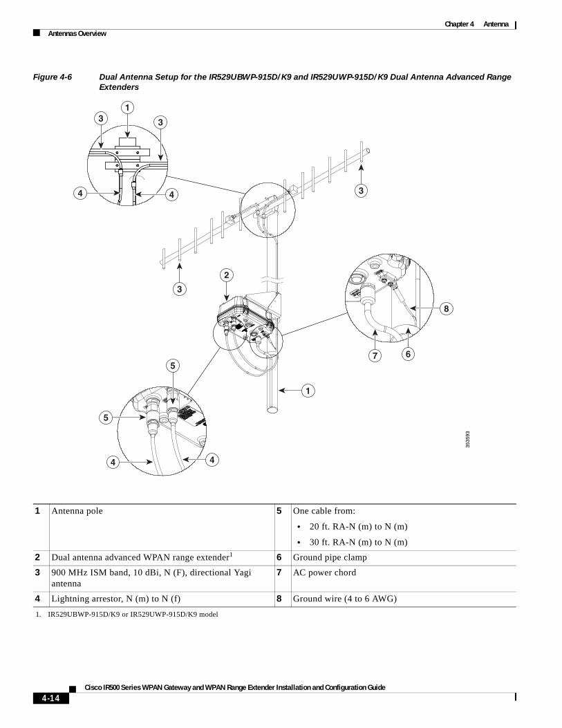
Figure 4-6 Dual Antenna Setup for the IR529UBWP-915D/K9 and IR529UWP-915D/K9 Dual Antenna Advanced Range
Extenders
1 Antenna pole 5 One cable from:
• 20 ft. RA-N (m) to N (m)
• 30 ft. RA-N (m) to N (m)
2 Dual antenna advanced WPAN range extender1
1. IR529UBWP-915D/K9 or IR529UWP-915D/K9 model
6 Ground pipe clamp
3 900 MHz ISM band, 10 dBi, N (F), directional Yagi antenna
7 AC power chord
4 Lightning arrestor, N (m) to N (f) 8 Ground wire (4 to 6 AWG)
3535
93
1
3
3
7 6
2
5
33
4
4
5
4
1
4
8
4-14Cisco IR500 Series WPAN Gateway and WPAN Range Extender Installation and Configuration Guide

Chapter 4 AntennaAdditional Information for WPAN Gateway Antenna Installations
Additional Information for WPAN Gateway Antenna Installations
For all outdoor antenna/WPAN gateway installations, the coax shield should be grounded (earthed) in accordance with ANSI/NFPA 70, the National Electrical Code (NEC), in particular Section 820.93, Grounding of Outer Conductive Shield of a Coaxial Cable.
In addition, please refer to Section 820.93 of the National Electrical Code, ANSI/NFPA 70: 2005; and EN60728-11: 2005, which provide guidelines for proper grounding and, in particular, specify that the coaxial cable shield shall be connected to the grounding system of the building, as close to the point of cable entry as practical.
For indoor antenna/WPAN gateway installations, no additional considerations are required.
Installing or Replacing AntennasDepending on the configuration you specified, the WPAN gateway and WPAN range extender could be shipped with all required antennas already installed and connected. You may need to install an antenna when you purchase an antenna separately to replace a faulty or damaged antenna.
For procedures and safety information required to install or replace antennas, see the Connected Grid Antenna Installation Guide, at: www.cisco.com/go/cg-modules.
4-15Cisco IR500 Series WPAN Gateway and WPAN Range Extender Installation and Configuration Guide

Chapter 4 AntennaInstalling or Replacing Antennas
4-16Cisco IR500 Series WPAN Gateway and WPAN Range Extender Installation and Configuration Guide