Antenna and Basestation Testing Challenges - Rohde & · PDF fileRF Measurements - LTE ... KPI...
40
Antenna and Basestation Testing Challenges Chee Chung TANG Target Account Management
Transcript of Antenna and Basestation Testing Challenges - Rohde & · PDF fileRF Measurements - LTE ... KPI...
Antenna and
Basestation Testing Challenges
Chee Chung TANGTarget Account Management
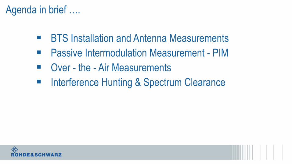
Agenda in brief ….
BTS Installation and Antenna Measurements
Passive Intermodulation Measurement - PIM
Over - the - Air Measurements
Interference Hunting & Spectrum Clearance
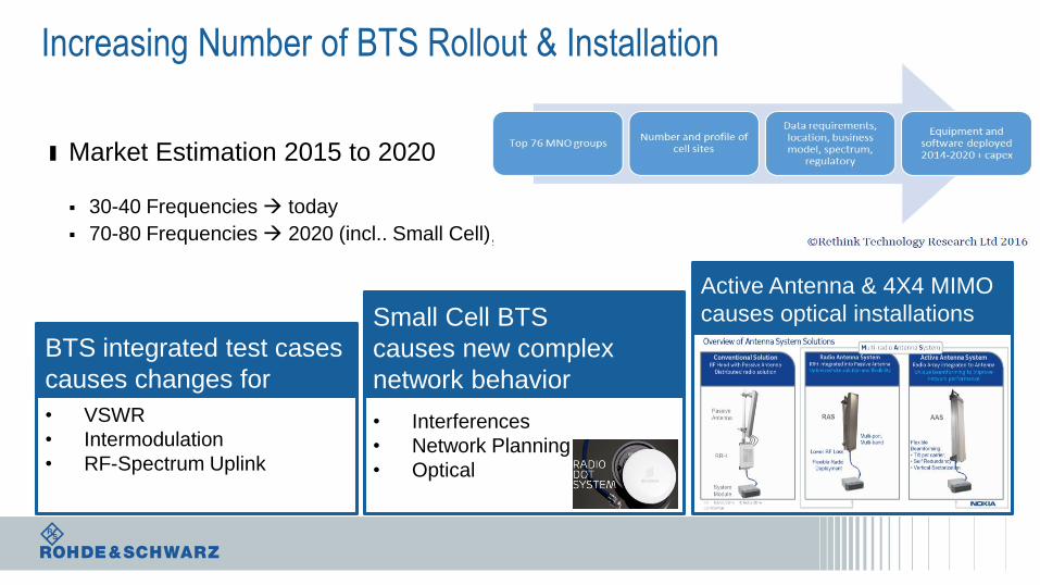
Increasing Number of BTS Rollout & Installation
ı Market Estimation 2015 to 2020
30-40 Frequencies today
70-80 Frequencies 2020 (incl.. Small Cell)
• VSWR
• Intermodulation
• RF-Spectrum Uplink
BTS integrated test cases
causes changes for
• Interferences
• Network Planning
• Optical
Small Cell BTS
causes new complex
network behavior • Optical & Platform
Active Antenna & 4X4 MIMO
causes optical installations
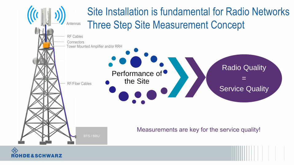
Antennas
Tower Mounted Amplifier and/or RRH
RF/Fiber Cables
BTS / BBU
RF Cables
Performance of the Site
Radio Quality
=
Service Quality
Connectors
Measurements are key for the service quality!
Site Installation is fundamental for Radio Networks
Three Step Site Measurement Concept

Antennas
Tower Mounted Amplifier and/or RRH
RF/Fiber Cables
BTS / BBU
RF Cables
Connectors
Agenda
BTS Installation and Antenna Measurements
Passive Intermodulation Measurement - PIM
Over - the - Air Measurements
Interference Hunting & Spectrum Clearance
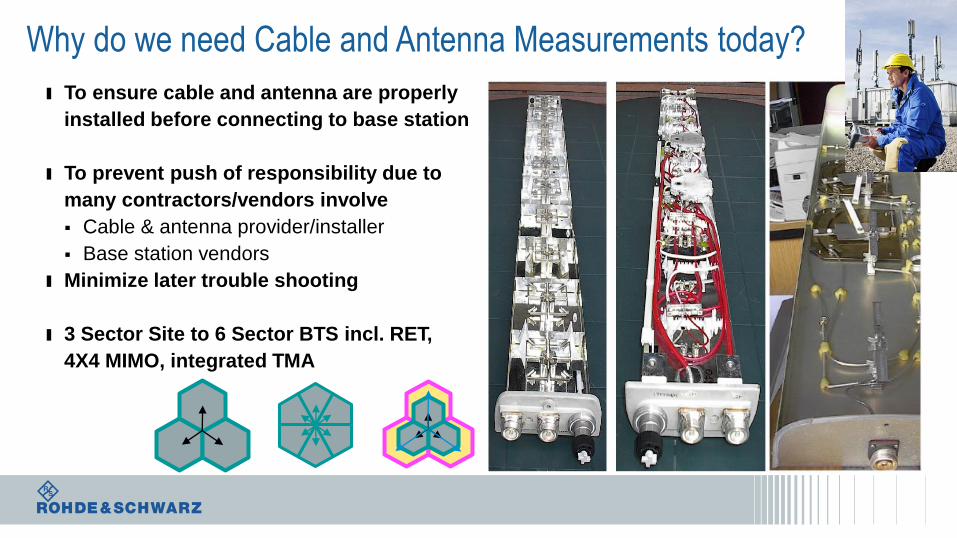
Why do we need Cable and Antenna Measurements today?
ı To ensure cable and antenna are properly
installed before connecting to base station
ı To prevent push of responsibility due to
many contractors/vendors involve
Cable & antenna provider/installer
Base station vendors
ı Minimize later trouble shooting
ı 3 Sector Site to 6 Sector BTS incl. RET,
4X4 MIMO, integrated TMA
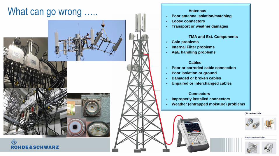
What can go wrong ….. Antennas
Poor antenna isolation/matching
Loose connectors
Transport or weather damages
TMA and Ext. Components
Gain problems
Internal Filter problems
A&E handling problems
Cables
Poor or corroded cable connection
Poor isolation or ground
Damaged or broken cables
Unpaired or interchanged cables
Connectors
Improperly installed connectors
Weather (entrapped moisture) problems
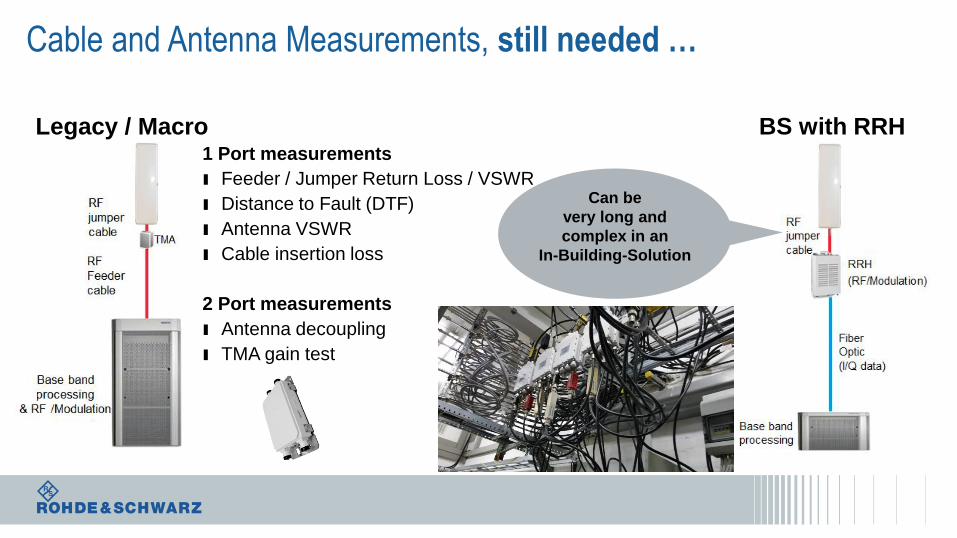
Cable and Antenna Measurements, still needed …
Legacy / Macro
BS
BS with RRH1 Port measurements
ı Feeder / Jumper Return Loss / VSWR
ı Distance to Fault (DTF)
ı Antenna VSWR
ı Cable insertion loss
2 Port measurements
ı Antenna decoupling
ı TMA gain test
Can be
very long and
complex in an
In-Building-Solution
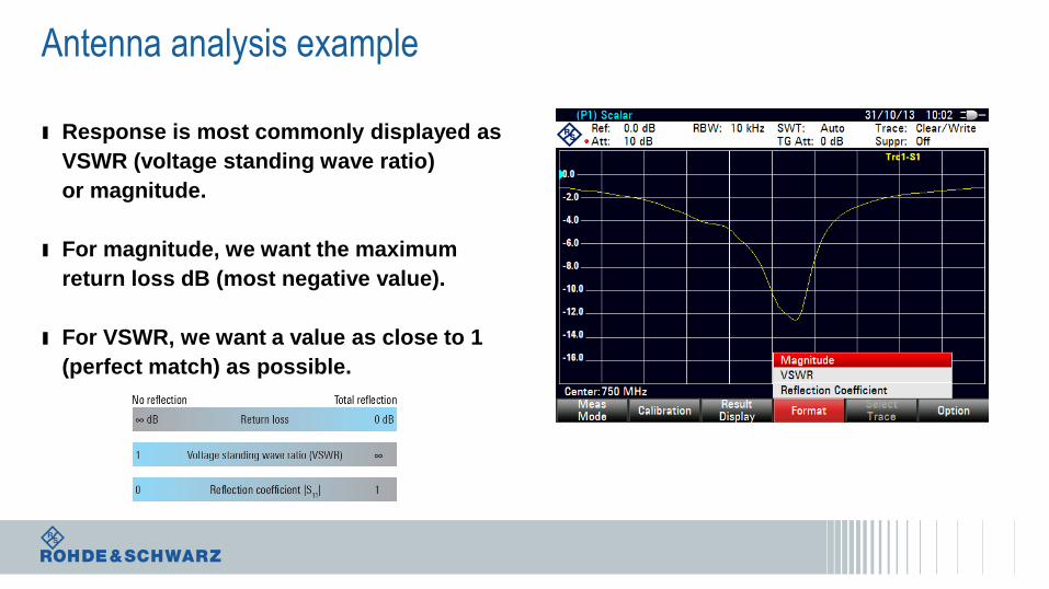
Antenna analysis example
ı Response is most commonly displayed as
VSWR (voltage standing wave ratio)
or magnitude.
ı For magnitude, we want the maximum
return loss dB (most negative value).
ı For VSWR, we want a value as close to 1
(perfect match) as possible.
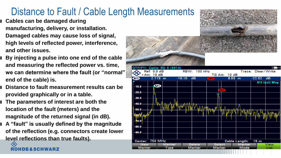
Distance to Fault / Cable Length Measurementsı Cables can be damaged during
manufacturing, delivery, or installation.
Damaged cables may cause loss of signal,
high levels of reflected power, interference,
and other issues.
ı By injecting a pulse into one end of the cable
and measuring the reflected power vs. time,
we can determine where the fault (or “normal”
end of the cable) is.
ı Distance to fault measurement results can be
provided graphically or in a table.
ı The parameters of interest are both the
location of the fault (meters) and the
magnitude of the returned signal (in dB).
ı A “fault” is usually defined by the magnitude
of the reflection (e.g. connectors create lower
level reflections than true faults).
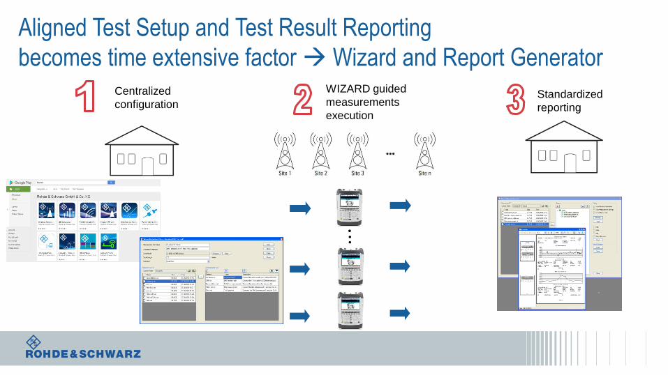
Aligned Test Setup and Test Result Reporting
becomes time extensive factor Wizard and Report GeneratorCentralized
configuration
WIZARD guided
measurements
execution
Standardized
reporting
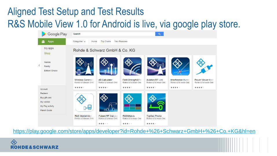
Aligned Test Setup and Test Results
R&S Mobile View 1.0 for Android is live, via google play store.
https://play.google.com/store/apps/developer?id=Rohde+%26+Schwarz+GmbH+%26+Co.+KG&hl=en
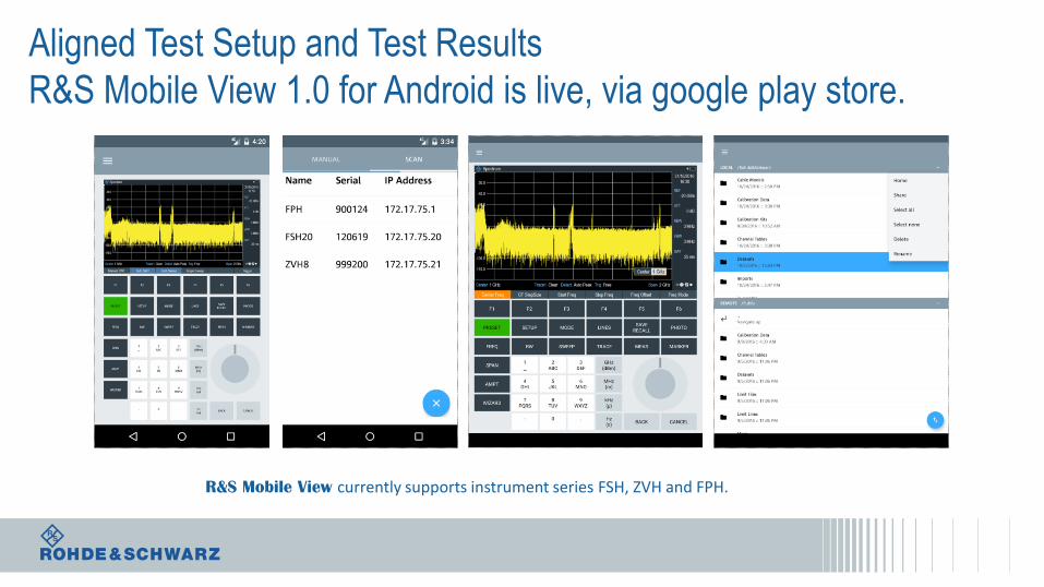
Aligned Test Setup and Test Results
R&S Mobile View 1.0 for Android is live, via google play store.
R&S Mobile View currently supports instrument series FSH, ZVH and FPH.
Agenda
BTS Installation and Antenna Measurements
Passive Intermodulation Measurement - PIM
Over - the - Air Measurements
Interference Hunting & Spectrum Clearance
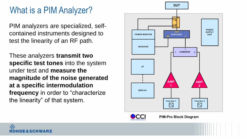
What is a PIM Analyzer?
PIM analyzers are specialized, self-
contained instruments designed to
test the linearity of an RF path.
These analyzers transmit two
specific test tones into the system
under test and measure the
magnitude of the noise generated
at a specific intermodulation
frequency in order to “characterize
the linearity” of that system.
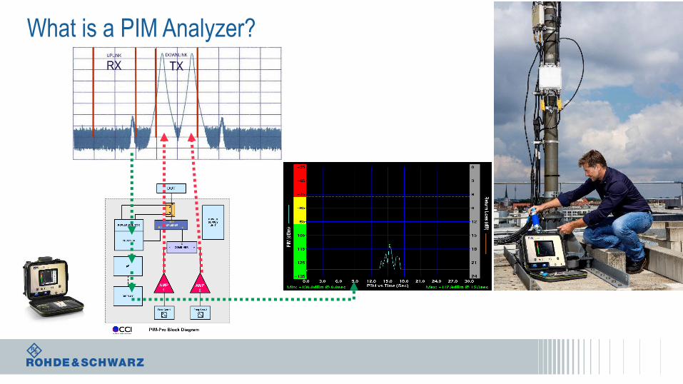
What is a PIM Analyzer?
Agenda in brief ….
BTS Installation and Antenna Measurements
Passive Intermodulation Measurement - PIM
Over - the - Air Measurements
Interference Hunting & Spectrum Clearance
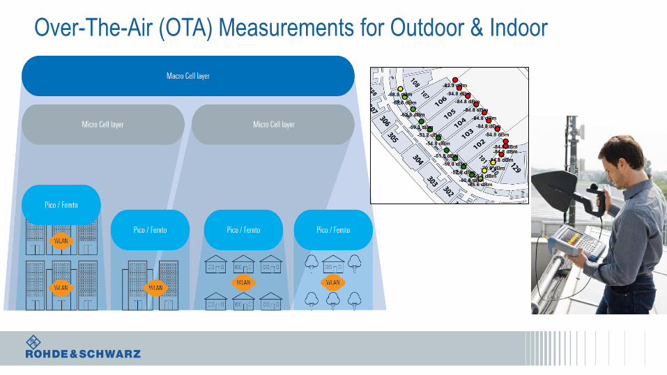
Over-The-Air (OTA) Measurements for Outdoor & Indoor
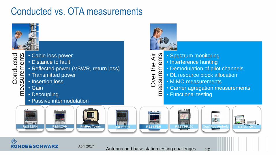
Conducted vs. OTA measurementsC
on
du
cte
d
me
asu
rem
en
ts • Cable loss power
• Distance to fault
• Reflected power (VSWR, return loss)
• Transmitted power
• Insertion loss
• Gain
• Decoupling
• Passive intermodulation
Ove
r th
e A
ir
me
asu
rem
en
ts • Spectrum monitoring
• Interference hunting
• Demodulation of pilot channels
• DL resource block allocation
• MIMO measurements
• Carrier agregation measurements
• Functional testing
R&S®ZVH R&S®FSHR&S®FPH R&S®PR100 QualiPoc Android R&S®TSMA
April 2017Antenna and base station testing challenges
PiMPro Tower
20
R&S®ZPH
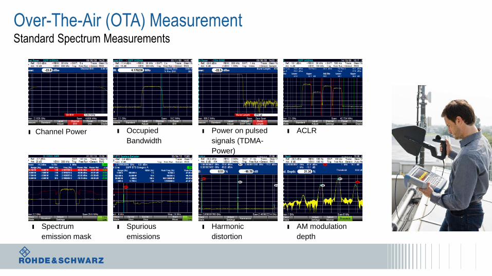
Over-The-Air (OTA) MeasurementStandard Spectrum Measurements
ı Spectrum
emission mask
ı Occupied
Bandwidth
ı Spurious
emissions
ı Power on pulsed
signals (TDMA-
Power)
ı Harmonic
distortion
ı ACLR
ı AM modulation
depth
ı Channel Power
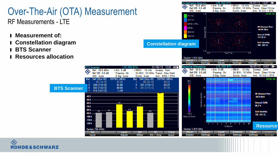
Over-The-Air (OTA) MeasurementRF Measurements - LTE
ı Measurement of:
ı Constellation diagram
ı BTS Scanner
ı Resources allocation
Constellation diagram
BTS Scanner
Resource allocation
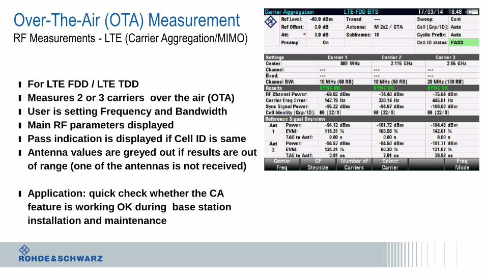
Over-The-Air (OTA) MeasurementRF Measurements - LTE (Carrier Aggregation/MIMO)
ı For LTE FDD / LTE TDD
ı Measures 2 or 3 carriers over the air (OTA)
ı User is setting Frequency and Bandwidth
ı Main RF parameters displayed
ı Pass indication is displayed if Cell ID is same
ı Antenna values are greyed out if results are out
of range (one of the antennas is not received)
ı Application: quick check whether the CA
feature is working OK during base station
installation and maintenance
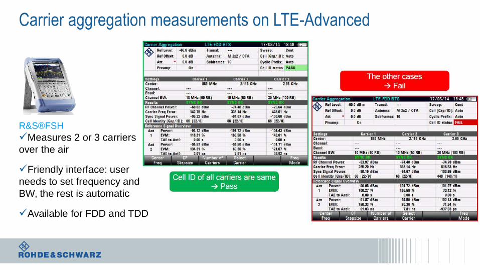
Carrier aggregation measurements on LTE-Advanced
R&S®FSH
Measures 2 or 3 carriers
over the air
Friendly interface: user
needs to set frequency and
BW, the rest is automatic
Available for FDD and TDD
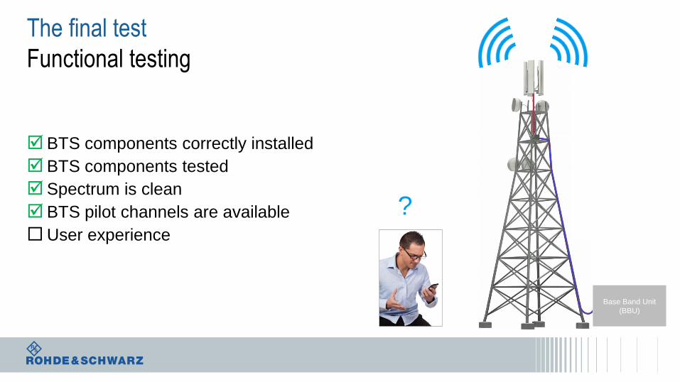
The final test
Functional testing
BTS components correctly installed
BTS components tested
Spectrum is clean
BTS pilot channels are available
User experience
Base Band Unit
(BBU)
?
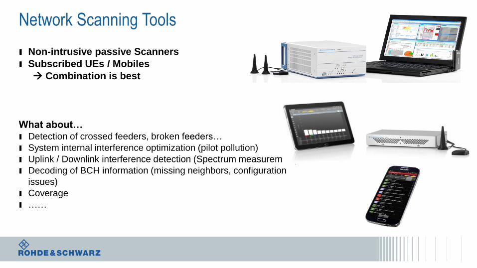
Network Scanning Tools
ı Non-intrusive passive Scanners
ı Subscribed UEs / Mobiles
Combination is best
What about…ı Detection of crossed feeders, broken feeders…
ı System internal interference optimization (pilot pollution)
ı Uplink / Downlink interference detection (Spectrum measurement)
ı Decoding of BCH information (missing neighbors, configuration
issues)
ı Coverage
ı ……
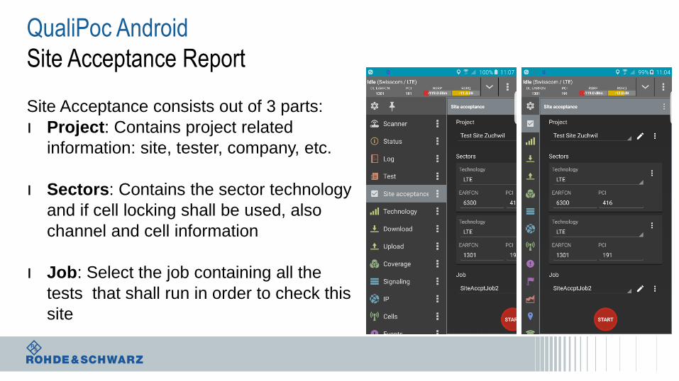
QualiPoc Android
Site Acceptance Report
Site Acceptance consists out of 3 parts:
ı Project: Contains project related
information: site, tester, company, etc.
ı Sectors: Contains the sector technology
and if cell locking shall be used, also
channel and cell information
ı Job: Select the job containing all the
tests that shall run in order to check this
site
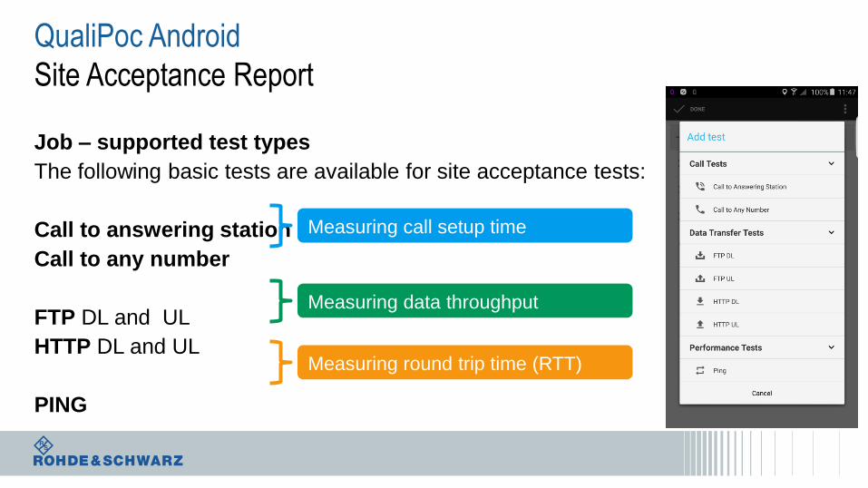
QualiPoc Android
Site Acceptance Report
Job – supported test types
The following basic tests are available for site acceptance tests:
Call to answering station
Call to any number
FTP DL and UL
HTTP DL and UL
PING
Measuring call setup time
Measuring data throughput
Measuring round trip time (RTT)
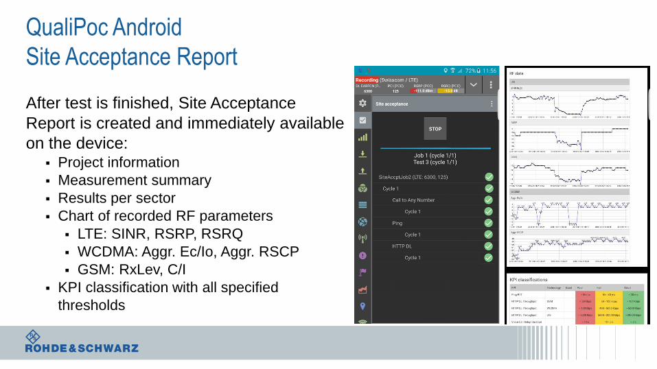
QualiPoc Android
Site Acceptance Report
After test is finished, Site Acceptance
Report is created and immediately available
on the device: Project information
Measurement summary
Results per sector
Chart of recorded RF parameters
LTE: SINR, RSRP, RSRQ
WCDMA: Aggr. Ec/Io, Aggr. RSCP
GSM: RxLev, C/I
KPI classification with all specified
thresholds
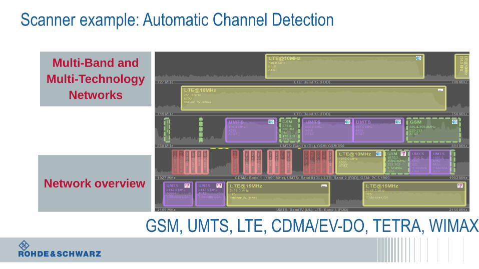
Scanner example: Automatic Channel Detection
Multi-Band and
Multi-Technology
Networks
Network overview
GSM, UMTS, LTE, CDMA/EV-DO, TETRA, WIMAX
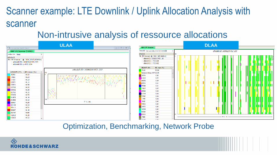
Non-intrusive analysis of ressource allocations
Scanner example: LTE Downlink / Uplink Allocation Analysis with
scanner
Optimization, Benchmarking, Network Probe
ULAA DLAA
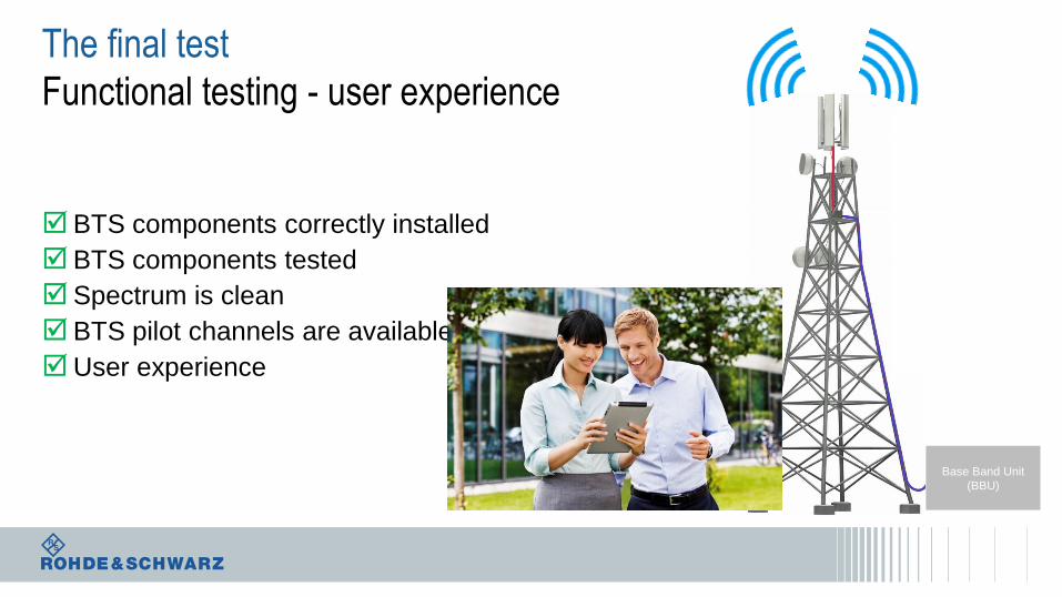
The final test
Functional testing - user experience
BTS components correctly installed
BTS components tested
Spectrum is clean
BTS pilot channels are available
User experience
Base Band Unit
(BBU)
Agenda in brief ….
BTS Installation and Antenna Measurements
Passive Intermodulation Measurement - PIM
Over - the - Air Measurements
Interference Hunting & Spectrum Clearance
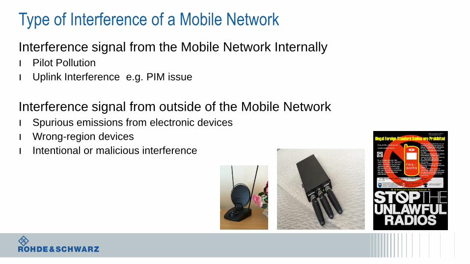
Type of Interference of a Mobile Network
Interference signal from the Mobile Network Internallyı Pilot Pollution
ı Uplink Interference e.g. PIM issue
Interference signal from outside of the Mobile Networkı Spurious emissions from electronic devices
ı Wrong-region devices
ı Intentional or malicious interference
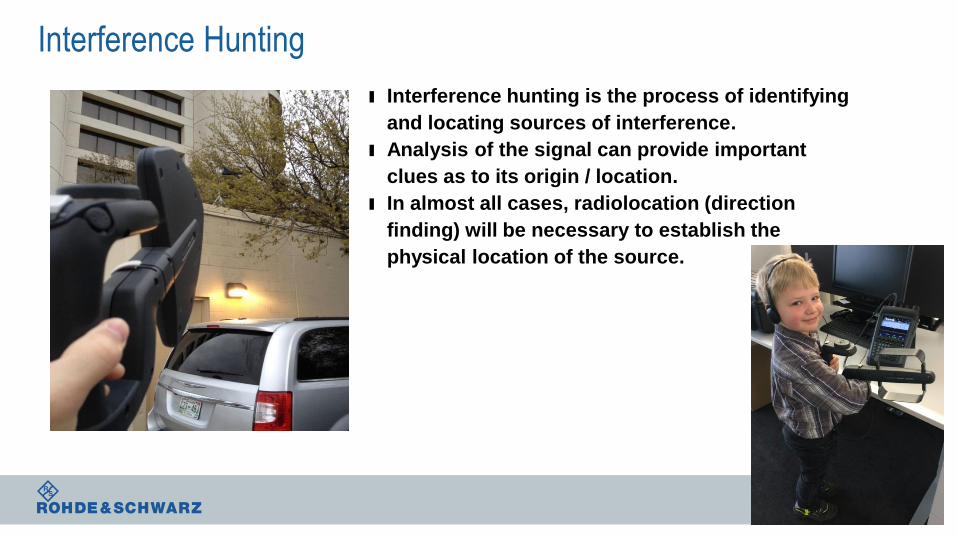
Interference Hunting
ı Interference hunting is the process of identifying
and locating sources of interference.
ı Analysis of the signal can provide important
clues as to its origin / location.
ı In almost all cases, radiolocation (direction
finding) will be necessary to establish the
physical location of the source.
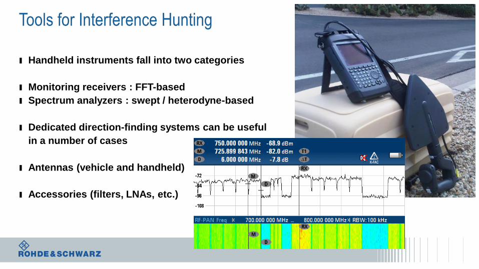
Tools for Interference Hunting
ı Handheld instruments fall into two categories
ı Monitoring receivers : FFT-based
ı Spectrum analyzers : swept / heterodyne-based
ı Dedicated direction-finding systems can be useful
in a number of cases
ı Antennas (vehicle and handheld)
ı Accessories (filters, LNAs, etc.)
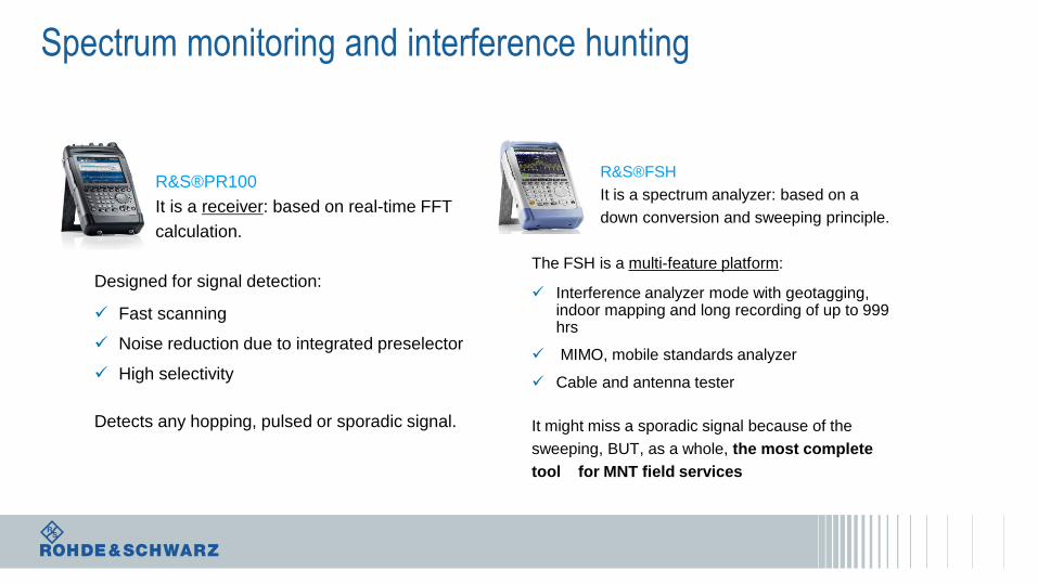
Spectrum monitoring and interference hunting
R&S®PR100
It is a receiver: based on real-time FFT
calculation.
Designed for signal detection:
Fast scanning
Noise reduction due to integrated preselector
High selectivity
Detects any hopping, pulsed or sporadic signal.
R&S®FSH
It is a spectrum analyzer: based on a
down conversion and sweeping principle.
The FSH is a multi-feature platform:
Interference analyzer mode with geotagging, indoor mapping and long recording of up to 999 hrs
MIMO, mobile standards analyzer
Cable and antenna tester
It might miss a sporadic signal because of the
sweeping, BUT, as a whole, the most complete
tool for MNT field services
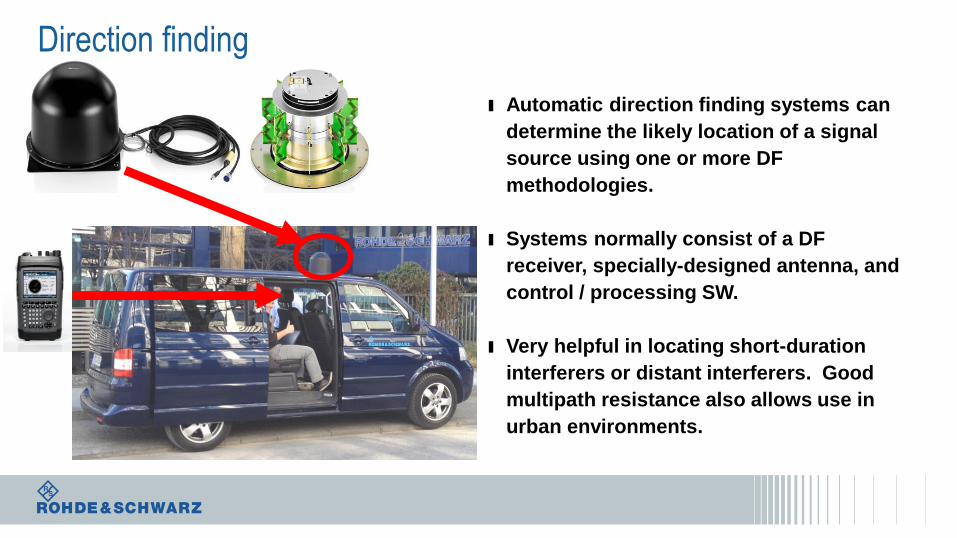
Direction finding
ı Automatic direction finding systems can
determine the likely location of a signal
source using one or more DF
methodologies.
ı Systems normally consist of a DF
receiver, specially-designed antenna, and
control / processing SW.
ı Very helpful in locating short-duration
interferers or distant interferers. Good
multipath resistance also allows use in
urban environments.
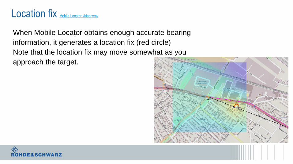
Location fix Mobile Locator video.wmv
When Mobile Locator obtains enough accurate bearing
information, it generates a location fix (red circle)
Note that the location fix may move somewhat as you
approach the target.

Thank you