Antenna ad Elica - IW0URG
12
Antenna ad Elica Helical/helix antenna cookbook recipe for 2.4 GHz wavelans and/or WiFi applications by Dr. Remco den Besten, PA3FYM (mail: helix at remco.tk) Bookmark/refer to this page as http://helix.remco.tk/ I innocently made this cookbook recipe and placed it on my local ADSL-connected machine, never expecting that so many of you want to have this information. This (co-located) bandwidth is kindly donated by ds9a.nl If you have IPv6 connectivity, look here (co-located at ISP Services.nl ) If you want to listen to MP3 audio streams using IPv6 as transport layer look here ( <- accessible with IPv4). Abstract 1 / 12
Transcript of Antenna ad Elica - IW0URG
Antenna ad Elica
Helical/helix antenna cookbook recipe
for 2.4 GHz wavelans and/or WiFi applications
by Dr. Remco den Besten, PA3FYM (mail: helix at remco.tk)
Bookmark/refer to this page as http://helix.remco.tk/ Iinnocently made this cookbook recipe and placed it on my localADSL-connected machine, never expecting that so many of youwant to have this information.This (co-located) bandwidth is kindly donated by ds9a.nl
If you have IPv6 connectivity, look here (co-located at ISPServices.nl)
If you want to listen to MP3 audio streams using IPv6 astransport layer look here ( <- accessible with IPv4).
Abstract
1 / 12
Antenna ad Elica
The helix antenna, invented in the late fourties by John Kraus(W8JK), can be considered as the genious ultimate simplicity asfar as antenna design is concerned. Especially for frequenciesin the range 2 - 5 GHz this design is very easy, practical, and,non critical. This contribution describes how to produce a helixantenna for frequencies around 2.4 GHz which can be used fore.g. high speed packet radio (S5-PSK, 1.288 Mbit/s), 2.4 GHzwavelans, and, amateur satellite (AO40). Developments inwavelan equipment result in easy possibilities for high speedwireless internet access using the 802.11b (aka WiFi) standard.
Theory in a birds eye viewThe helix antenna can be considered as a spring with N turnswith a reflector. The circumference (C) of a turn isapproximately one wavelength (l), and, the distance (d)between the turns is approx. 0.25C. The size of the reflector (R)is equal to C or l, and can be a circle or a square. The designyields circular polarization (CP), which can be either 'right hand'or 'left hand' (RHCP or LHCP respectively), depending uponhow the helix is wound. To have maximum transfer of energy,both ends of the link must use the same polarization, unlessyou use a (passive) reflector in the radio path.The gain (G) of the antenna, relative to an isotrope (dBi), canbe estimated by:
2 / 12

Antenna ad Elica
G = 11.8 + 10 * log {(C/l)^2 * N * d} dBi (1)
According to Dr. Darrel Emerson (AA7FV) of the NationalRadio Astronomy Observatory, the results from [1], also knownas the 'Kraus formula', are 4 - 5 dB too optimistic. Dr. Ray Cross(WK0O) inserted the results from Emerson in an antennaanalysis program called 'ASAP'.
The characteristic impedance (Z) of the resulting 'transmissionline' empirically seems to be:
Z = 140 * (C/l) Ohm (2)
Practical design for 2.43 GHz (aka S-band, ISM band, 13 cmamateur band)
l = (0.3/2.43) = 0.1234567 m ;-)(12.34 cm) (3)
3 / 12

Antenna ad Elica
The diameter (D) of one turn = (l/pi) = 39.3 mm (4)
Standard PVC sewer pipe with an outer diameter of 40 mm isperfect for the job and can be obtained easily (at least in TheNetherlands ;-) from a 'do it yourself' shop or a plumber. Thehelix will be wound with standard wire used to interconnect220V AC outlets in (Dutch ;-) house holds. This wire has acolourized PVC isolation and a 1.5 mm thick copper core.Winding it around the PVC pipe will result in D = ca. 42 mm,due to the thickness of the isolation.
With D = 42 mm, C = 42*pi = 132 mm (which is 1.07 l) (5)
Now d = 0.25C = 0.25*132 = 33 mm (6)
For distances ranging from 100 m - 2.5 km with line of sight, 12turns (N = 12) are sufficient. The length of the PVC pipetherefore will be 40 cm (3.24 l). Turn the wire around the PVCpipe and glue it with PVC glue or any other glue containingtetrahydrofurane (THF). The result will be a very solid helixwound along the pipe, see figure 1 below.
4 / 12

Antenna ad Elica
Figure 1. Overview of some of the materials used anddimensions.The impedance of the antenna, which is: Z = 140 * (C/l) = 140*{(42*pi)/123.4} = 150 Ohm (7) requires a matching network on order to apply standard 50Ohm UHF/SHF coax and connectors. The use of a 1/4-wave matching stub with an impedance (Zs) of: Zs = sqrt(Z1*Z2) = sqrt(50*150) = 87 Ohm (8) is very common. Due to the helix design, this equals 1/4 turn.However, from a mechanical point of view -bearing water proofaspects in mind when using the antenna outdoors- there aremore preferred methods to match the helix to 50 Ohm. My firstthoughts were to empirically decrease d for the first and secondturn and match the helix using the 'trial and error'-method, whilemeasuring the results with a directional coupler, and signalgenerator. Browsing the internet for while I found helicesmatched this way , but surprisingly I bumped into the page of Jason Hecker. He really used an elegant way to match his helix by using acopper vane, referring to the ARRL Handbook. So, full creditsgo to the ARRL and Jason, and I used his dimensions for thevane. To be honest, this page seems to be a duplicate of hispage, except that our helices are wound the other way around!!Yes, and I am left handed, so, is this a coincidence? It is funnyanyway :-)) For details, see figure 2 (below).
5 / 12

Antenna ad Elica
6 / 12

Antenna ad Elica
Figures 2a and 2b. The idea, the dimensions, and, mountingthe stub. The hypotenusa of the stub should follow the wire.Now with some luck and skills solder the stub to the helix, glueit, and prepare the contrapsion to be inserted intothe cap, see figure 3.
Figure 3. Almost finished helix antenna. And.... ready! (figure 4)
7 / 12

Antenna ad Elica
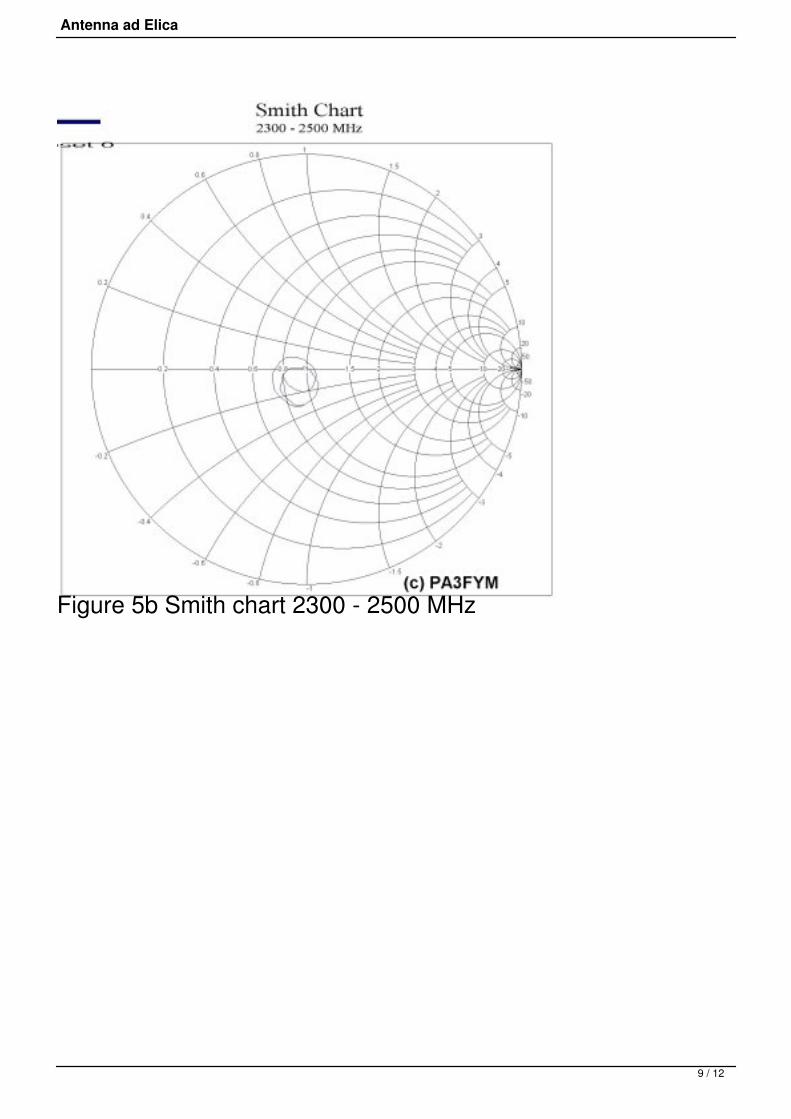
Figure 4. Finished 12 turn 2.4 GHz helix antenna, G = 17.5 dBior 13.4 dBi (Kraus or Emerson respectively) The antenna was sweeped an measured. The results are givenbelow (figures 5a and 5b)
Figure 5a Return loss (dB) from 2300 - 2500 MHz
8 / 12
Antenna ad Elica
Figure 5b Smith chart 2300 - 2500 MHz
9 / 12

Antenna ad Elica
Figure 6a Measurement setup
Figure 6b 'helix-in-one-hour' and Rohde & Schwarz analyser And... finally.... the helix 'in action'....
10 / 12
Antenna ad Elica
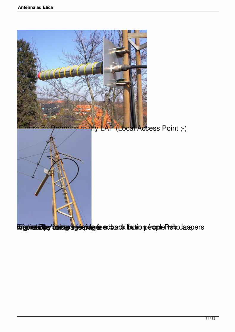
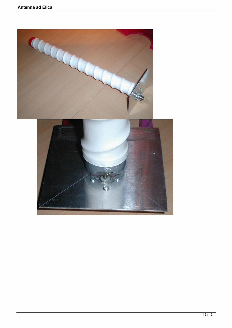
Figure 7a Beaming to my LAP (Local Access Point ;-)
Figure 7b 'bottom view' It is really nice to receive feedback from people who areinspired by this page. Here a contribution from Rob Jasperswho madehis helices using this page:
11 / 12
Antenna ad Elica
12 / 12