Ansys vs NX Nastran
22
-
Upload
allen-jose-george -
Category
Documents
-
view
1.643 -
download
18
Transcript of Ansys vs NX Nastran


Topic details
Validate the meshes generated on a
complex part model
Mesh generation via NX 7.5 algorithm and
Ansys
Meshed geometries are to be simulated
using UGS NX 7.5 Nastran Solver
Need of the Project
Large scale organization depends heavily on its strategies towards the Digitization.
NX is being used for modeling; ANSYS used for meshing and Analysis.
Shortfalls in data transfer between these two.
Tools for translating the NX data into neutral format available.
But iterative design process make it impractical
NX is identified here as a tool that can be tried out for meshing the components.

Unigraphics NX 7.5
NX Unigraphics, is an advanced CAD/CAM/CAE
software package developed by Siemens PLM
Software.
The NX software integrates geometric modeling,
advanced analysis, graphic simulation, and concurrent
engineering.
Offers major enhancements across the existing product
portfolio in the areas of multi-body dynamics, meshing,
laminate composites and support for multiphysics
solvers.

UGS NX Modeling
Unique Features Feature operations such as Cone, Sphere, Block etc
Boolean operations to existing bodies viz. Unite,
Subtract and Intersect.
UGS NX Modeling
Modeling Modes
History mode Creates and edits the model using an ordered sequence of
features that are displayed in the Part Navigator.
History-Free mode User creates and edits the model based on its current
state, without an ordered sequence of features.
A local feature modifies only the local geometry, without
the need to update and replay a global feature tree.

Synchronous Modeling
Synchronous Modeling commands help us work effectively in History–free mode. With these commands, our modeling
One can use Synchronous Modeling commands to easily modify the model, regardless of how it was created.
Move face Example

UGS NX Assemblies
They are added to the part file in such a way that the parts are virtual in the assembly and linked to the original part.
There are two basic ways of creating any assembly model. Top down approach
The assembly part file is created first and components are created in that file. Then individual parts are modeled.
Bottom up approach The component parts are created first in the traditional
way and then added to the assembly part file
UGS NX Assemblies
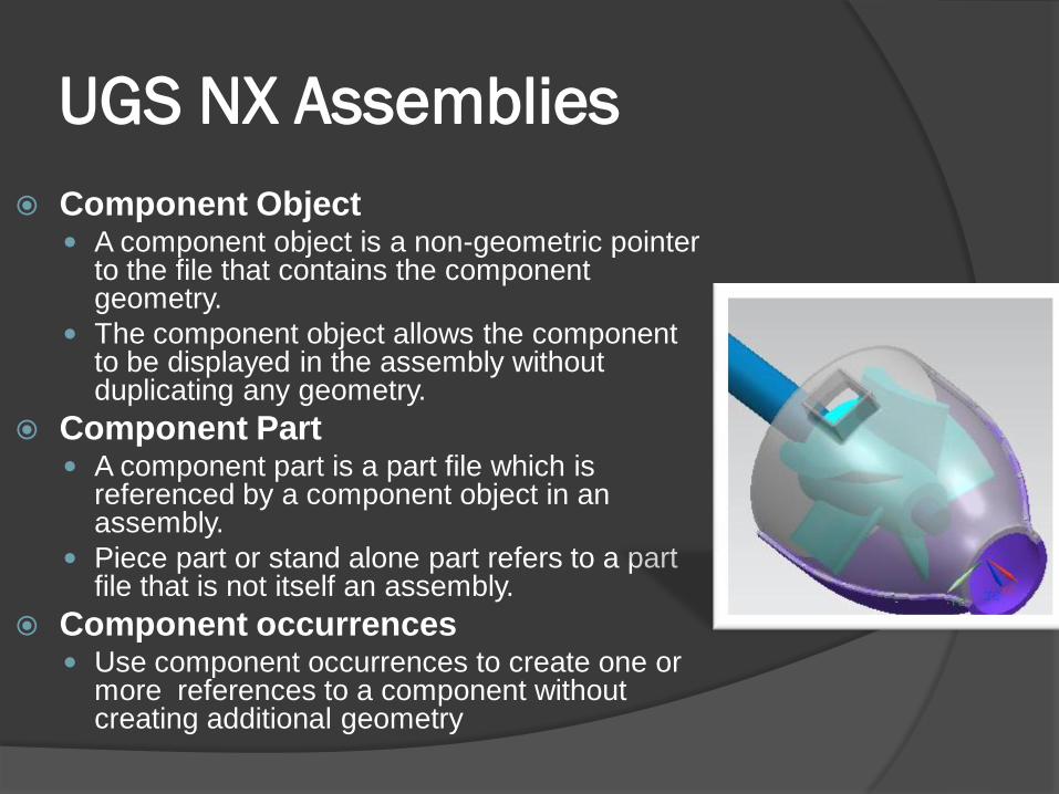
Component Object A component object is a non-geometric pointer
to the file that contains the component geometry.
The component object allows the component to be displayed in the assembly without duplicating any geometry.
Component Part A component part is a part file which is
referenced by a component object in an assembly.
Piece part or stand alone part refers to a part file that is not itself an assembly.
Component occurrences Use component occurrences to create one or
more references to a component without creating additional geometry

UGS NX Advanced Simulation
Overview
Comprehensive finite element modeling and results visualization product\
Provides support for industry-standard solvers, such as NX Nastran, ANSYS, and ABAQUS.
We specify the solver we plan to use to solve our model and the type of analysis we want to perform.
The software then presents all meshing, boundary conditions, and solution options using the terminology or “language” of that solver and analysis type.

CAE model files
The idealized part file ( i part )
The idealized part file is the result of geometry clean up.
Often many features on the part file are not necessarily significant to the simulation.
Include minute grooves, chamfers and fillet.
The master part is a component of the idealized part.
All modifications are stored with the idealized part file, and the original master model geometry is unaltered.

CAE model files
The Finite Element Method file ( fem part )
The FEM file is the master model for the Simulation file.
It is not an assembly and contains no components.
It contains nodes, elements, and physical and
material property tables.
May be associative or non-associative.
CAE model files
The Simulation file ( sim part )
The Simulation (.sim) file is an NX assembly with the fem part as its only component.
Comprises loads, constraints and other boundary conditions that define our analysis.
Access to the mesh and polygon geometry in the FEM file when defining our Simulation.
Multiple simulation files can include the same FEM as a component in the same scenario. This allows us to reuse mesh data for different analyses.

Meshing in UGS NX
Element shapes and nodes

Mesh types and Options
3D Tetrahedral mesh
We can use 3D Tetrahedral Mesh to generate a
mesh of linear or parabolic tetrahedral elements.
The software abstracts the selected polygon
geometry to remove small surfaces or edges
The software bases this abstraction on the
specified Element Size and Small Feature
Tolerance in the 3D Tetrahedral Mesh dialog
box.

3D Swept Mesh
The 3D Swept Mesh command is used to generate a mapped mesh of hexahedral.
Done by weeping a free or mapped surface mesh through a solid body.
Structured mesh with layer by layer consistency on any 2 ½ dimensional solid body

Mesh control
Mesh Control to create edge and face densities for free and mapped meshes.
Local control over the number and distribution pattern of elements along a particular edge or across a particular face.
Options are Number on Edge, Size on Edge, Size on face, Side bias etc

Tet Mesh v/s Hex Mesh
Tet Meshing
Fully Automated
Generate millions of elements in short time span
Adequate for some analysis but not for others
Hex Meshing
Partially Automated, some Manual
Generating elements takes much longer
Preferred by most analysts for solution quality
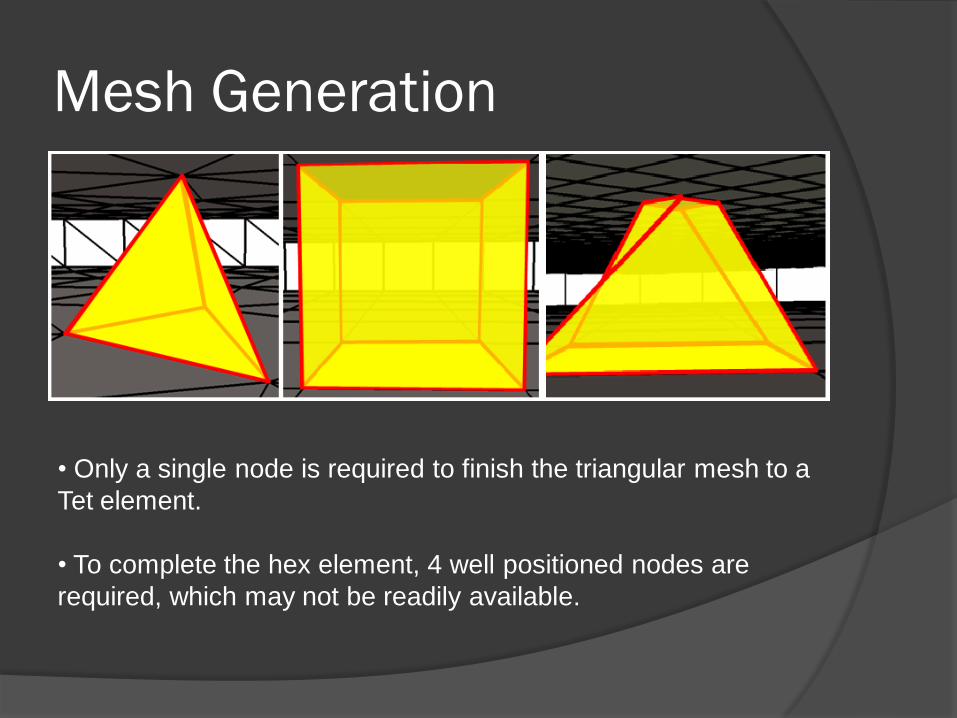
Mesh Generation
• Only a single node is required to finish the triangular mesh to a
Tet element.
• To complete the hex element, 4 well positioned nodes are
required, which may not be readily available.
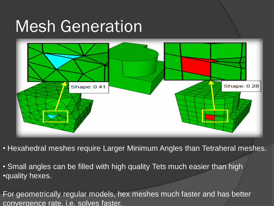
Mesh Generation
• Hexahedral meshes require Larger Minimum Angles than Tetraheral meshes.
• Small angles can be filled with high quality Tets much easier than high
•quality hexes.
For geometrically regular models, hex meshes much faster and has better
convergence rate, i.e. solves faster.

Solution Creation NX7.5 creates a folder of the same name as that of the file and at the
same location where the file is located.
Results generated for the scenarios are saved as .vdm files.
It creates five different files with the name of the scenario viz. xxx.SIM,
xxx.DAT, xxx.txt, xxx.out and xxx.VDM
Models Completed Bracket
Wastegate diaphragm
Model Satellite
Compressor Blade
Work Due• Under the meshing section of the project,
iterative process of meshing is left over.
• Simulation section work on Automatic Coupling, Applying Constraint Equations, checking 1D/2D Connections, Analysis and Identify & Apply BC's is due to be finished by the first week of April