
ANSI/NEMA MW 1000-2012 - IHS Inc.€¦ · ANSI/NEMA MW 1000-2012 Revision of ANSI MW1000-2008...
21
ANSI/NEMA MW 1000-2012 Revision of ANSI MW1000-2008 American National Standard Magnet Wire Secretariat: National Electrical Manufacturers Association Approved April 8, 2013 Published May 28, 2013 American National Standards Institute
Transcript of ANSI/NEMA MW 1000-2012 - IHS Inc.€¦ · ANSI/NEMA MW 1000-2012 Revision of ANSI MW1000-2008...
ANSI/NEMA MW 1000-2012 Revision of ANSI MW1000-2008
American National Standard
Magnet Wire
Secretariat:
National Electrical Manufacturers Association
Approved April 8, 2013
Published May 28, 2013
American National Standards Institute

MW 1000-2012 Part 0, Page 2
© Copyright 2013 by National Electrical Manufacturers Association
NOTICE AND DISCLAIMER
The information in this publication was considered technically sound by the consensus of persons engaged in the development and approval of the document at the time it was developed. Consensus does not necessarily mean that there is unanimous agreement among every person participating in the development of this document. American National Standards Institute (ANSI) standards and guidelines publications, of which the document contained herein is one, are developed through a voluntary consensus standards development process. This process brings together volunteers and/or seeks out the views of person who have interest in the topic covered by this publication. While NEMA administers the process to promote fairness in the development of consensus, it does not write the document and it does not independently test, evaluate, or verify the accuracy or completeness of any information or the soundness of any judgments contained in its standards and guideline publications. NEMA disclaims liability for any personal injury, property, or other damages of any nature whatsoever, whether special, indirect, consequential, or compensatory, directly or indirectly resulting from the publication, use of, application, or reliance on this document. NEMA disclaims and makes no guaranty or warranty, express or implied, as to the accuracy or completeness of any information published herein, and disclaims and makes no warranty that the information in this document will fulfill any of your particular purposes or needs. NEMA does not undertake to guarantee the performance of any individual manufacturer or seller’s products or services by virtue of this standard or guide. In publishing and making this document available, NEMA is not undertaking to render professional or other services for or on behalf of any person or entity, nor is NEMA undertaking to perform any duty owed by any person or entity to someone else. Anyone using this document should rely on his or her own independent judgment or, as appropriate, seek the advice of a competent professional in determining the exercise of reasonable care in any given circumstances. Information and other standards on the topic covered by this publication may be available from other sources, which the user may wish to consult for additional views or information not covered by this publication. NEMA has no power, nor does it undertake to police or enforce compliance with the contents of this document. NEMA does not certify, test, or inspect products, designs, or installations for safety or health purposes. Any certification or other statement of compliance with any health or safety-related information in this document shall not be attributable to NEMA and is solely the responsibility of the certifier or maker of the statement.

MW 1000-2012 Part 0, Page 3
© Copyright 2013 by National Electrical Manufacturers Association
Summary of Revisions
MW 1000-2012
Amendments following the publication of MW 1000-2008, Revision 3-2011 Amendments from Revision 4-2012 are indicated by an orange vertical line in left margin of revised page. Note: Where text has been revised in more than one version, only the most recent is color-coded.
Introductory Material Updated tables of contents........................................................................................................................ i–xii
Updated Foreword ....................................................................................................................................... xiii
Part 1
Table 1.5.1.3 ... revised to accurately reflect relation between percentage of overlap and no. of tape layers; Formula for minimum thickness or diameter increase to take into account tape stretching factor ............. 31
1.6.7.1 Revised to clarify the method for determining bare wire diameter based on AWG and to update the wire size range in which special maximum bare wire dimensions apply in table 1 ............................... 34
1.7 Revised to clarify the methodology applied for determining millimeter dimensions ............................. 35
Table 1: Revised max bare dimensions for 2 and 3 AWG .................................................................... 39, 42
Table 1: Added reference to 1.6.7.1 for special considerations for 2–13.5 AWG magnet wire ............ 41, 44
Table 1: Revised mm dimensions to reflect clarified methodology for calculating these ....................... 42-44
Table 1: Editorially revised to include MW 16-C Quad minimum increases and maximum OD’s ......... 39-44
Tables 13 through 18: Revised titles indicating standard dimensions and added reference to Appendix E for dimensions other than those provided in the table. .......................................................................... 60-65
Table 25: Revised to take account an 85% stretch factor inherent in wire manufacturing processes ... 77-79
Table 27: Revised to take account an 85% stretch factor inherent in wire manufacturing processes ... 81-82
Part 2 MW 15-A, 15-C, 18-A, 18-C, 20-C, 35-A, 35-C, 36-A, 36-C, 37-C, 38-C, 41-C, 42-C, 43-C, 44-C, 45-C, 46-C, 47-C, 48-C, 50-C, 51-C, 52-C, 53-C, 60-A, 60-C, 61-A, 61-C, 64-C, 65-C, 74-A, 74-C, 81-C: revised to reference new shot electrode procedure for dielectric breakdown .............................................. Per MW No.
New MW 31-A specification ...................................................................................................................... 104
MW 31-C: revised dimensional, adherence and flexibility, and dielectric breakdown requirements ......... 105
New MW 33-A specification ...................................................................................................................... 106
MW 31-C, 33-C 60-A, 60-C, 61-A, 61-C, 64-C and 65-C: removal of reference to table 25 ....... Per MW No.
MW 62-C, 63-C: obsolete specifications ............................................................................................ 131-132
MW 64-C: editorial addition of square wire dimensions ............................................................................ 133
New MW 84-C specification ...................................................................................................................... 151
New MW 132-C specification .................................................................................................................... 156
New MW 137-C specification .................................................................................................................... 159
MW 1000-2012 Part 0, Page 4
© Copyright 2013 by National Electrical Manufacturers Association
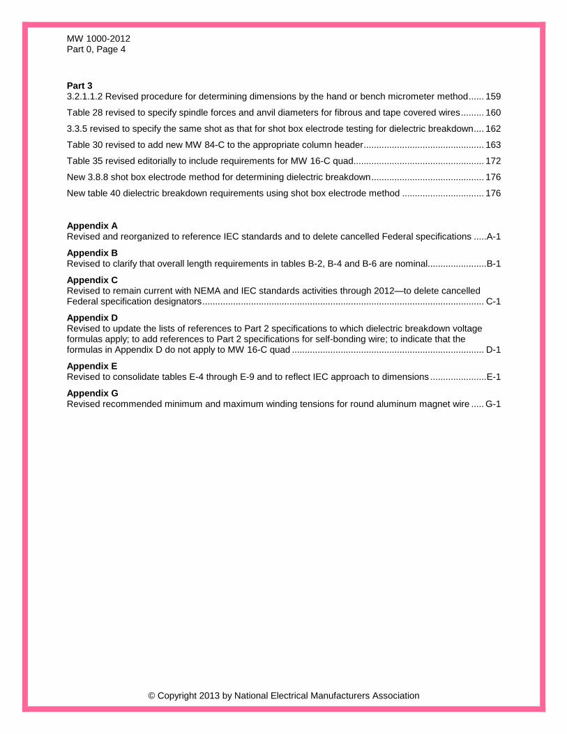
Part 3 3.2.1.1.2 Revised procedure for determining dimensions by the hand or bench micrometer method ...... 159
Table 28 revised to specify spindle forces and anvil diameters for fibrous and tape covered wires ......... 160
3.3.5 revised to specify the same shot as that for shot box electrode testing for dielectric breakdown .... 162
Table 30 revised to add new MW 84-C to the appropriate column header ............................................... 163
Table 35 revised editorially to include requirements for MW 16-C quad................................................... 172
New 3.8.8 shot box electrode method for determining dielectric breakdown ............................................ 176
New table 40 dielectric breakdown requirements using shot box electrode method ................................ 176
Appendix A Revised and reorganized to reference IEC standards and to delete cancelled Federal specifications ..... A-1
Appendix B Revised to clarify that overall length requirements in tables B-2, B-4 and B-6 are nominal....................... B-1
Appendix C Revised to remain current with NEMA and IEC standards activities through 2012—to delete cancelled Federal specification designators .............................................................................................................. C-1
Appendix D Revised to update the lists of references to Part 2 specifications to which dielectric breakdown voltage formulas apply; to add references to Part 2 specifications for self-bonding wire; to indicate that the formulas in Appendix D do not apply to MW 16-C quad ........................................................................... D-1
Appendix E Revised to consolidate tables E-4 through E-9 and to reflect IEC approach to dimensions ...................... E-1
Appendix G Revised recommended minimum and maximum winding tensions for round aluminum magnet wire ..... G-1

MW 1000-2012 Part 0, Page 11
© Copyright 2013 by National Electrical Manufacturers Association
TABLE OF CONTENTS
Page
Foreword .................................................................................................................................. 24
How to Use this Publication ..................................................................................................... 25
Part 1
GENERAL
1.1 SCOPE .................................................................................................................................... 27
1.2 NORMATIVE REFERENCES AND AUTHORIZED ENGINEERING INFORMATION (AEI) ... 27
1.3 DEFINITIONS .......................................................................................................................... 28
1.4 MATERIALS ............................................................................................................................ 30
1.4.1 Conductors—Round, Square, and Rectangular, Copper and Aluminum ................................ 30 1.4.2 Insulating Materials .................................................................................................................. 30
1.5 MANUFACTURING ................................................................................................................. 31
1.5.1 Application of Insulation ........................................................................................................... 31 1.5.2 Intermediate Sizes ................................................................................................................... 32 1.5.3 Joints…………….…………………………………………………………………………………..... 32 1.5.4 Packaging ................................................................................................................................ 32
1.6 TEST CONDITIONS AND PARAMETERS ............................................................................. 33
1.6.1 Safety Statement ..................................................................................................................... 33 1.6.2 Selection of Specimens ........................................................................................................... 33 1.6.3 Ambient Conditions of Test ..................................................................................................... 33 1.6.4 Power Frequency ..................................................................................................................... 33 1.6.5 Mandrels .................................................................................................................................. 33 1.6.6 Rectangular and Square Wire ................................................................................................. 34 1.6.7 Round Wire .............................................................................................................................. 34 1.6.8 Periodic Conformance ............................................................................................................. 35 1.6.9 Retests ………………………………………………………………………………………………. . 35
1.7 UNITS OF MEASURE ............................................................................................................. 35
1.8 THERMAL CLASS OF MAGNET WIRE .................................................................................. 35
1.9. ORDERING INFORMATION ................................................................................................... 36
1.9.1 Product Identification Number ................................................................................................. 36 1.9.2 Minimum Ordering Data .......................................................................................................... 36
1.10 DE-REELING (WINDING) TENSION ..................................................................................... 37
Tables
1 Dimensions for Bare and Film Insulated Round Magnet Wire ....................................................... 39
2 Round Copper Wire, Ultra-Fine Sizes by Resistance .................................................................... 45
3 Dimensions for Round Film Insulated Self-Bonding Magnet Wire ................................................. 46
4 Dimensions for Single Glass Fiber Covered Round Bare, Single Film Coated and Heavy Film Coated Wire ................................................................................................................................... 48
5 Dimensions for Double Glass Fiber Covered Round Bare, Single Film Coated and Heavy Film Coated Wire ................................................................................................................................... 50

MW 1000-2012 Part 0, Page 12
© Copyright 2013 by National Electrical Manufacturers Association
6 Dimensions for Single Polyester Glass Fiber Covered Round Bare, Single Film Coated and Heavy Film Coated Wire ................................................................................................................ 52
7 Dimensions for Double Polyester Glass Fiber Covered Round Bare, Single Film Coated and Heavy Film Coated Wire ................................................................................................................ 54
8 Dimensions, Radii and Cross-Sectional Area for Standard Rectangular Bare Wire ...................... 56
9 Bare Rectangular Conductor Tolerances [Deleted] ....................................................................... 57
10 Film Insulated Rectangular Magnet Wire Increase in Thickness and Width Due to Film Coating .......................................................................................................................................... 57
11 Dimensions of Square Bare Wire ................................................................................................... 58
12 Heavy and Quadruple Film Insulated Square Magnet Wire Increase in Dimensions Due to Film Coating……… ........................................................................................................................ 59
13 Range of Increase in Dimensions, Inches Single Glass Fiber Covered Heavy Film Insulated Rectangular Copper Wire............................................................................................................... 60
14 Range of Increase in Dimensions, Inches Double Glass Fiber Covered Bare Rectangular Copper Wire ..... ……………………………………………………………………………………………61
15 Range of Increase in Dimensions, Inches Double Glass Fiber Covered Heavy Film Coated Rectangular Copper Wire............................................................................................................... 62
16 Range of Increase in Dimensions, Inches Single Polyester Glass Fiber Covered Heavy Film Insulated Rectangular Copper Wire ............................................................................................... 63
17 Range of Increase in Dimensions, Inches Double Polyester Glass Fiber Covered Bare Rectangular Copper Wire............................................................................................................... 64
18 Range of Increase in Dimensions, Inches Double Polyester Glass Fiber Covered Heavy Film Coated Rectangular Copper Wire .................................................................................................. 65
19 Single Glass Fiber Covered, Heavy Film Insulated Square Copper Magnet Wire—
Minimum Increase and Maximum Overall Dimensions Due to Insulation ...................................... 66
20 Single Polyester Glass Fiber Covered Heavy Film Insulated Square Copper Magnet
Wire—Minimum Increase and Maximum Overall Dimensions Due to Insulation .......................... 67
21 Double Glass Fiber Covered, Bare or Heavy Film Insulated Square Copper Magnet Wire Minimum Increase and Maximum Overall Dimensions Due to Insulation ...................................... 68
22 Double Polyester Glass Fiber Covered, Bare or Heavy Film Insulated Square Copper
Magnet Wire—Minimum Increase and Maximum Overall Dimensions Due to Insulation ............. 69
23 Comparison Between AWG and IEC R-40 Series Bare Wire Diameters ...................................... 70
24 Comparison Between NEMA and IEC Increases and Overall Diameters ...................................... 73
25 Dimensions for Tape Covered Round Magnet Wire……………………………………………... ...... 77
26 Increase in Dimensions of Rectangular Wire Due to Tape Covering………………………….. ...... 80
27 Dimensions for Tape Covered Square Magnet Wire…………………………………………….. ...... 81
MW 1000-2012 Part 0, Page 13
© Copyright 2013 by National Electrical Manufacturers Association
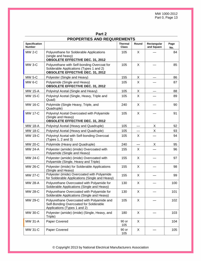
Part 2
PROPERTIES AND REQUIREMENTS
Specification
Number
Thermal
Class
Round Rectangular
and Square
Page
No.
MW 2-C Polyurethane for Solderable Applications (single and heavy)
OBSOLETE EFFECTIVE DEC. 31, 2012
105 X — 84
MW 3-C Polyurethane with Self-bonding Overcoat for Solderable Applications (Types 1 and 2)
OBSOLETE EFFECTIVE DEC. 31, 2012
105 X — 85
MW 5-C Polyester (Single and Heavy) 155 X — 86
MW 6-C Polyamide (Single and Heavy)
OBSOLETE EFFECTIVE DEC. 31, 2012
105 X — 87
MW 15-A Polyvinyl Acetal (Single and Heavy) 105 X — 88
MW 15-C Polyvinyl Acetal (Single, Heavy, Triple and Quad)
105 X — 89
MW 16-C Polyimide (Single Heavy, Triple, and Quadruple)
240 X — 90
MW 17-C Polyvinyl Acetal Overcoated with Polyamide (Single and Heavy)
OBSOLETE EFFECTIVE DEC. 31, 2012
105 X — 91
MW 18-A Polyvinyl Acetal (Heavy and Quadruple) 105 — X 92
MW 18-C Polyvinyl Acetal (Heavy and Quadruple) 105 — X 93
MW 19-C Polyvinyl Acetal with Self-bonding Overcoat (Types 1, 2 and 3)
105 X — 94
MW 20-C Polyimide (Heavy and Quadruple) 240 — X 95
MW 24-A Polyester (amide) (imide) Overcoated with Polyamide (Single and Heavy)
155 X — 96
MW 24-C Polyester (amide) (imide) Overcoated with Polyamide (Single, Heavy and Triple)
155 X — 97
MW 26-C Polyester (imide) for Solderable Applications (Single and Heavy)
155 X — 98
MW 27-C Polyester (imide) Overcoated with Polyamide for Solderable Applications (Single and Heavy)
155 X — 99
MW 28-A Polyurethane Overcoated with Polyamide for Solderable Applications (Single and Heavy)
130 X — 100
MW 28-C Polyurethane Overcoated with Polyamide for Solderable Applications (Single and Heavy)
130 X — 101
MW 29-C Polyurethane Overcoated with Polyamide and Self-Bonding Overcoated for Solderable Applications (Types 1 and 2)
105 X — 102
MW 30-C Polyester (amide) (imide) (Single, Heavy, and Triple)
180 X — 103
MW 31-A Paper Covered 90 or 105
X 104
MW 31-C Paper Covered 90 or 105
X — 105
MW 1000-2012 Part 0, Page 14
© Copyright 2013 by National Electrical Manufacturers Association
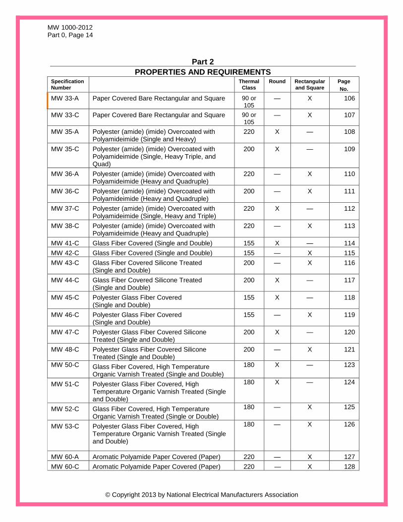
Part 2
PROPERTIES AND REQUIREMENTS
Specification
Number
Thermal
Class
Round Rectangular
and Square
Page
No.
MW 33-A Paper Covered Bare Rectangular and Square 90 or 105
— X 106
MW 33-C Paper Covered Bare Rectangular and Square 90 or 105
— X 107
MW 35-A Polyester (amide) (imide) Overcoated with Polyamideimide (Single and Heavy)
220 X — 108
MW 35-C Polyester (amide) (imide) Overcoated with Polyamideimide (Single, Heavy Triple, and Quad)
200 X — 109
MW 36-A Polyester (amide) (imide) Overcoated with Polyamideimide (Heavy and Quadruple)
220 — X 110
MW 36-C Polyester (amide) (imide) Overcoated with Polyamideimide (Heavy and Quadruple)
200 — X 111
MW 37-C Polyester (amide) (imide) Overcoated with Polyamideimide (Single, Heavy and Triple)
220 X — 112
MW 38-C Polyester (amide) (imide) Overcoated with Polyamideimide (Heavy and Quadruple)
220 — X 113
MW 41-C Glass Fiber Covered (Single and Double) 155 X — 114
MW 42-C Glass Fiber Covered (Single and Double) 155 — X 115
MW 43-C Glass Fiber Covered Silicone Treated (Single and Double)
200 — X 116
MW 44-C Glass Fiber Covered Silicone Treated (Single and Double)
200 X — 117
MW 45-C Polyester Glass Fiber Covered (Single and Double)
155 X — 118
MW 46-C Polyester Glass Fiber Covered (Single and Double)
155 — X 119
MW 47-C Polyester Glass Fiber Covered Silicone Treated (Single and Double)
200 X — 120
MW 48-C Polyester Glass Fiber Covered Silicone Treated (Single and Double)
200 — X 121
MW 50-C Glass Fiber Covered, High Temperature Organic Varnish Treated (Single and Double)
180 X — 123
MW 51-C Polyester Glass Fiber Covered, High Temperature Organic Varnish Treated (Single and Double)
180 X — 124
MW 52-C Glass Fiber Covered, High Temperature Organic Varnish Treated (Single or Double)
180 — X 125
MW 53-C Polyester Glass Fiber Covered, High Temperature Organic Varnish Treated (Single and Double)
180 — X 126
MW 60-A Aromatic Polyamide Paper Covered (Paper) 220 — X 127
MW 60-C Aromatic Polyamide Paper Covered (Paper) 220 — X 128
MW 1000-2012 Part 0, Page 15
© Copyright 2013 by National Electrical Manufacturers Association
Part 2
PROPERTIES AND REQUIREMENTS
Specification
Number
Thermal
Class
Round Rectangular
and Square
Page
No.
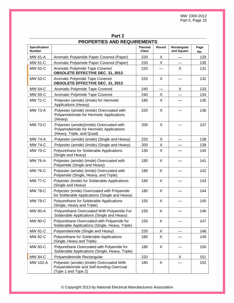
MW 61-A Aromatic Polyamide Paper Covered (Paper) 220 X — 129
MW 61-C Aromatic Polyamide Paper Covered (Paper) 220 X — 130
MW 62-C Aromatic Polyimide Tape Covered
OBSOLETE EFFECTIVE DEC. 31, 2013
220 — X 131
MW 63-C Aromatic Polyimide Tape Covered
OBSOLETE EFFECTIVE DEC. 31, 2013
220 X — 132
MW 64-C Aromatic Polyimide Tape Covered 240 — X 133
MW 65-C Aromatic Polyimide Tape Covered 240 X — 134
MW 72-C Polyester (amide) (imide) for Hermetic Applications (Heavy)
180 X — 135
MW 73-A Polyester (amide) (imide) Overcoated with Polyamideimide for Hermetic Applications (Heavy)
220 X — 136
MW 73-C Polyester (amide)(imide) Overcoated with Polyamideimide for Hermetic Applications (Heavy, Triple, and Quad)
200 X — 137
MW 74-A Polyester (amide) (imide) (Single and Heavy) 220 X — 138
MW 74-C Polyester (amide) (imide) (Single and Heavy) 200 X — 139
MW 75-C Polyurethane for Solderable Applications (Single and Heavy)
130 X — 140
MW 76-A Polyester (amide) (imide) Overcoated with Polyamide (Single and Heavy)
180 X — 141
MW 76-C Polyester (amide) (imide) Overcoated with Polyamide (Single, Heavy, and Triple)
180 X — 142
MW 77-C Polyester (imide) for Solderable Applications (Single and Heavy)
180 X — 143
MW 78-C Polyester (imide) Overcoated with Polyamide for Solderable Applications (Single and Heavy)
180 X — 144
MW 79-C Polyurethane for Solderable Applications (Single, Heavy and Triple)
155 X — 145
MW 80-A Polyurethane Overcoated With Polyamide For Solderable Applications (Single and Heavy)
155 X — 146
MW 80-C Polyurethane Overcoated with Polyamide for Solderable Applications (Single, Heavy, Triple)
155 X — 147
MW 81-C Polyamideimide (Single and Heavy) 220 X — 148
MW 82-C Polyurethane for Solderable Applications (Single, Heavy and Triple)
180 X — 149
MW 83-C Polyurethane Overcoated with Polyamide for Solderable Applications (Single, Heavy, Triple)
180 X — 150
MW 84-C Polyamideimide Rectangular 220 X 151
MW 102-A Polyester (amide) (imide) Overcoated With Polyamideimide and Self-bonding Overcoat (Type 1 and Type 2)
180 X — 152

MW 1000-2012 Part 0, Page 16
© Copyright 2013 by National Electrical Manufacturers Association
Part 2
PROPERTIES AND REQUIREMENTS
Specification
Number
Thermal
Class
Round Rectangular
and Square
Page
No.
MW 102-C Polyester (amide)(imide) Overcoated with Polyamideimide and Self-bonding Overcoat (Type 1 and Type 2)
180 X — 153
MW 130-C Polyurethane with self-bonding overcoat (Type 1 and Type 2)
130 X — 154
MW 131-C Polyurethane with Self-Bonding Overcoat (Type 1 and Type 2)
155 X — 155
MW 132-C Solderable Polyurethane with Self-Bonding Overcoat
180 X 156
MW 135-C Polyurethane Overcoated with Polyamide and Self-Bonding Overcoat (Type 1 and Type 2)
130 X — 157
MW 136-C Polyurethane Overcoated with Polyamide and Self-Bonding Overcoat (Type 1 and Type 2)
155 X — 158
MW 137-C Solderable Polyurethane Overcoated with Polyamide and Self-Bonding Overcoat
180 X 159
MW 1000-2012 Part 0, Page 17
© Copyright 2013 by National Electrical Manufacturers Association
Part 2
PROPERTIES AND REQUIREMENTS LISTING BY THERMAL CLASS,
INSULATION, COATING, AND FORM
Thermal Class Insulation, Covering and Form See Part 2, Section
Aluminum Copper Page No.
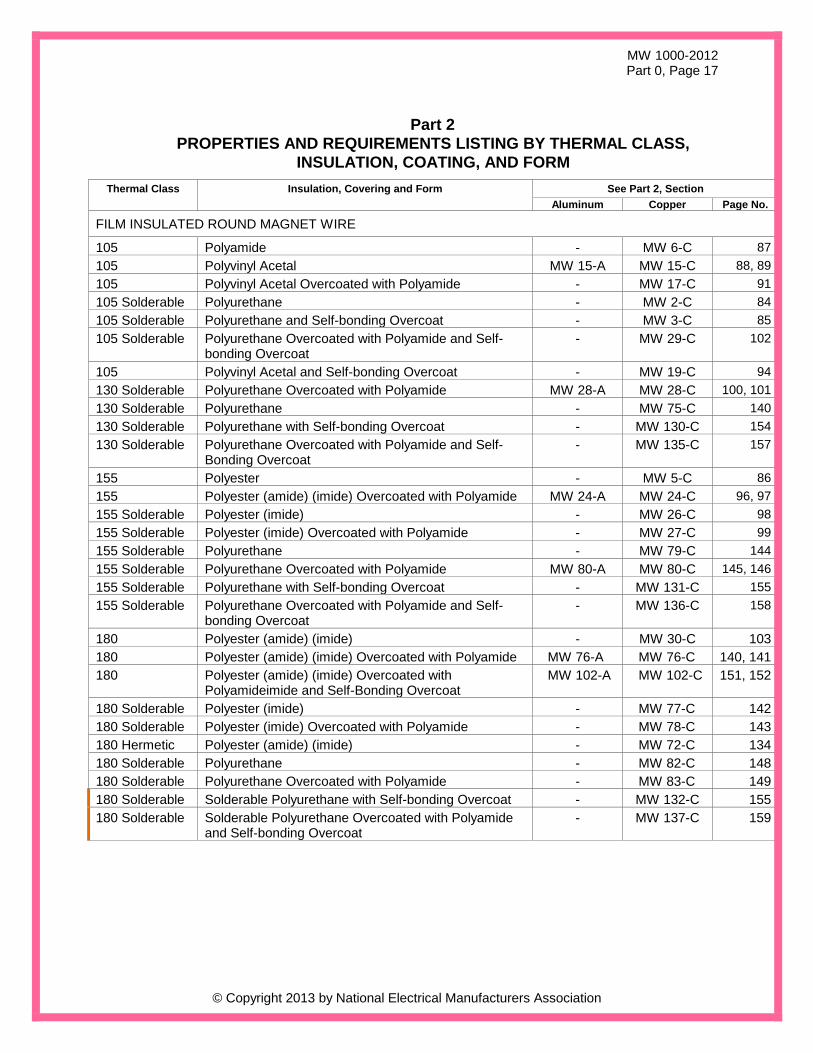
FILM INSULATED ROUND MAGNET WIRE
105 Polyamide - MW 6-C 87
105 Polyvinyl Acetal MW 15-A MW 15-C 88, 89
105 Polyvinyl Acetal Overcoated with Polyamide - MW 17-C 91
105 Solderable Polyurethane - MW 2-C 84
105 Solderable Polyurethane and Self-bonding Overcoat - MW 3-C 85
105 Solderable Polyurethane Overcoated with Polyamide and Self-bonding Overcoat
- MW 29-C 102
105 Polyvinyl Acetal and Self-bonding Overcoat - MW 19-C 94
130 Solderable Polyurethane Overcoated with Polyamide MW 28-A MW 28-C 100, 101
130 Solderable Polyurethane - MW 75-C 140
130 Solderable Polyurethane with Self-bonding Overcoat - MW 130-C 154
130 Solderable Polyurethane Overcoated with Polyamide and Self-Bonding Overcoat
- MW 135-C 157
155 Polyester - MW 5-C 86
155 Polyester (amide) (imide) Overcoated with Polyamide MW 24-A MW 24-C 96, 97
155 Solderable Polyester (imide) - MW 26-C 98
155 Solderable Polyester (imide) Overcoated with Polyamide - MW 27-C 99
155 Solderable Polyurethane - MW 79-C 144
155 Solderable Polyurethane Overcoated with Polyamide MW 80-A MW 80-C 145, 146
155 Solderable Polyurethane with Self-bonding Overcoat - MW 131-C 155
155 Solderable Polyurethane Overcoated with Polyamide and Self-bonding Overcoat
- MW 136-C 158
180 Polyester (amide) (imide) - MW 30-C 103
180 Polyester (amide) (imide) Overcoated with Polyamide MW 76-A MW 76-C 140, 141
180 Polyester (amide) (imide) Overcoated with Polyamideimide and Self-Bonding Overcoat
MW 102-A MW 102-C 151, 152
180 Solderable Polyester (imide) - MW 77-C 142
180 Solderable Polyester (imide) Overcoated with Polyamide - MW 78-C 143
180 Hermetic Polyester (amide) (imide) - MW 72-C 134
180 Solderable Polyurethane - MW 82-C 148
180 Solderable Polyurethane Overcoated with Polyamide - MW 83-C 149
180 Solderable Solderable Polyurethane with Self-bonding Overcoat - MW 132-C 155
180 Solderable Solderable Polyurethane Overcoated with Polyamide and Self-bonding Overcoat
- MW 137-C 159
MW 1000-2012 Part 0, Page 18
© Copyright 2013 by National Electrical Manufacturers Association
Part 2
PROPERTIES AND REQUIREMENTS LISTING BY THERMAL CLASS,
INSULATION, COATING, AND FORM
Thermal Class Insulation, Covering and Form See Part 2, Section
Aluminum Copper Page No.
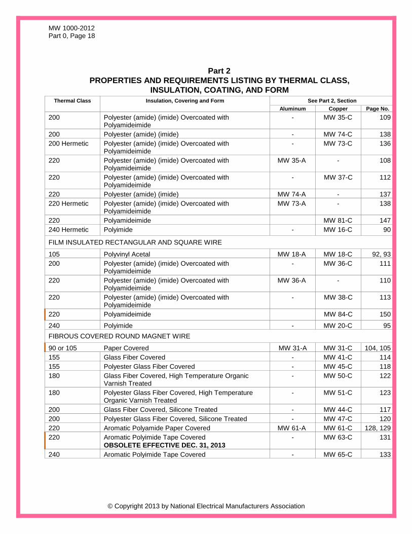
200 Polyester (amide) (imide) Overcoated with Polyamideimide
- MW 35-C 109
200 Polyester (amide) (imide) - MW 74-C 138
200 Hermetic Polyester (amide) (imide) Overcoated with Polyamideimide
- MW 73-C 136
220 Polyester (amide) (imide) Overcoated with Polyamideimide
MW 35-A - 108
220 Polyester (amide) (imide) Overcoated with Polyamideimide
- MW 37-C 112
220 Polyester (amide) (imide) MW 74-A - 137
220 Hermetic Polyester (amide) (imide) Overcoated with Polyamideimide
MW 73-A - 138
220 Polyamideimide MW 81-C 147
240 Hermetic Polyimide - MW 16-C 90
FILM INSULATED RECTANGULAR AND SQUARE WIRE
105 Polyvinyl Acetal MW 18-A MW 18-C 92, 93
200 Polyester (amide) (imide) Overcoated with Polyamideimide
- MW 36-C 111
220 Polyester (amide) (imide) Overcoated with Polyamideimide
MW 36-A - 110
220 Polyester (amide) (imide) Overcoated with Polyamideimide
- MW 38-C 113
220 Polyamideimide MW 84-C 150
240 Polyimide - MW 20-C 95
FIBROUS COVERED ROUND MAGNET WIRE
90 or 105 Paper Covered MW 31-A MW 31-C 104, 105
155 Glass Fiber Covered - MW 41-C 114
155 Polyester Glass Fiber Covered - MW 45-C 118
180 Glass Fiber Covered, High Temperature Organic Varnish Treated
- MW 50-C 122
180 Polyester Glass Fiber Covered, High Temperature Organic Varnish Treated
- MW 51-C 123
200 Glass Fiber Covered, Silicone Treated - MW 44-C 117
200 Polyester Glass Fiber Covered, Silicone Treated - MW 47-C 120
220 Aromatic Polyamide Paper Covered MW 61-A MW 61-C 128, 129
220 Aromatic Polyimide Tape Covered
OBSOLETE EFFECTIVE DEC. 31, 2013
- MW 63-C 131
240 Aromatic Polyimide Tape Covered - MW 65-C 133

MW 1000-2012 Part 0, Page 19
© Copyright 2013 by National Electrical Manufacturers Association
Part 2
PROPERTIES AND REQUIREMENTS LISTING BY THERMAL CLASS,
INSULATION, COATING, AND FORM
Thermal Class Insulation, Covering and Form See Part 2, Section
Aluminum Copper Page No.
FIBROUS COVERED RECTANGULAR & SQUARE MAGNET WIRE
90 or 105 Paper Covered MW 33-A MW 33-C 106, 107
155 Glass Fiber Covered - MW 42-C 115
155 Polyester Glass Fiber Covered - MW 46-C 119
180 Glass Fiber Covered, High Temperature Organic Varnish Treated
- MW 52-C 124
180 Polyester Glass Fiber Covered, High Temperature Organic Varnish Treated
- MW 53-C 125
200 Glass Fiber Covered, Silicone Treated - MW 43-C 116
200 Polyester Glass Fiber Covered, Silicone Treated - MW 48-C 121
220 Aromatic Polyamide Paper Covered MW 60-A MW 60-C 126, 127
220 Aromatic Polyimide Tape Covered
OBSOLETE EFFECTIVE DEC. 31, 2013
- MW 62-C 130
240 Aromatic Polyimide Tape Covered - MW 64-C 132
MW 1000-2012 Part 0, Page 20
© Copyright 2013 by National Electrical Manufacturers Association
Part 3
TEST PROCEDURES
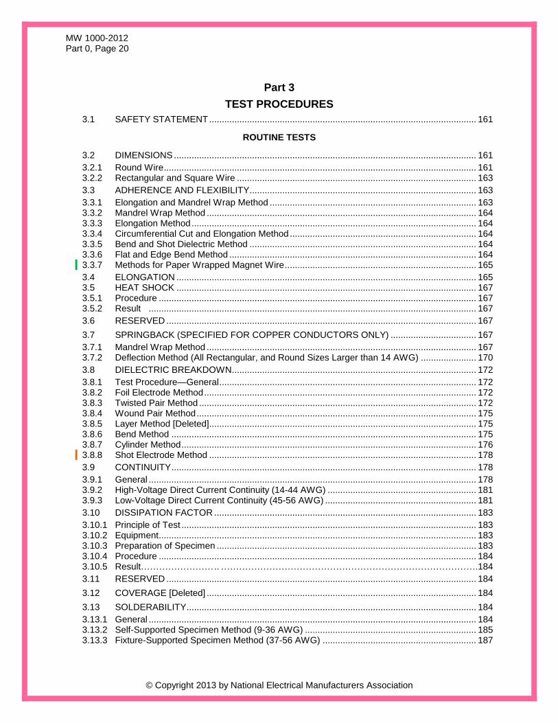
3.1 SAFETY STATEMENT .......................................................................................................... 161
ROUTINE TESTS
3.2 DIMENSIONS ........................................................................................................................ 161
3.2.1 Round Wire ............................................................................................................................ 161 3.2.2 Rectangular and Square Wire ............................................................................................... 163
3.3 ADHERENCE AND FLEXIBILITY .......................................................................................... 163
3.3.1 Elongation and Mandrel Wrap Method .................................................................................. 163 3.3.2 Mandrel Wrap Method ........................................................................................................... 164 3.3.3 Elongation Method ................................................................................................................. 164 3.3.4 Circumferential Cut and Elongation Method .......................................................................... 164 3.3.5 Bend and Shot Dielectric Method .......................................................................................... 164 3.3.6 Flat and Edge Bend Method .................................................................................................. 164 3.3.7 Methods for Paper Wrapped Magnet Wire ............................................................................ 165
3.4 ELONGATION ....................................................................................................................... 165 3.5 HEAT SHOCK ....................................................................................................................... 167 3.5.1 Procedure .............................................................................................................................. 167 3.5.2 Result .................................................................................................................................. 167
3.6 RESERVED ........................................................................................................................... 167
3.7 SPRINGBACK (SPECIFIED FOR COPPER CONDUCTORS ONLY) .................................. 167
3.7.1 Mandrel Wrap Method ........................................................................................................... 167 3.7.2 Deflection Method (All Rectangular, and Round Sizes Larger than 14 AWG) ...................... 170
3.8 DIELECTRIC BREAKDOWN ................................................................................................. 172
3.8.1 Test Procedure—General ...................................................................................................... 172 3.8.2 Foil Electrode Method ............................................................................................................ 172 3.8.3 Twisted Pair Method .............................................................................................................. 172 3.8.4 Wound Pair Method ............................................................................................................... 175 3.8.5 Layer Method [Deleted] .......................................................................................................... 175 3.8.6 Bend Method ......................................................................................................................... 175 3.8.7 Cylinder Method ..................................................................................................................... 176 3.8.8 Shot Electrode Method .......................................................................................................... 178
3.9 CONTINUITY ......................................................................................................................... 178
3.9.1 General .................................................................................................................................. 178 3.9.2 High-Voltage Direct Current Continuity (14-44 AWG) ........................................................... 181 3.9.3 Low-Voltage Direct Current Continuity (45-56 AWG) ............................................................ 181
3.10 DISSIPATION FACTOR ........................................................................................................ 183
3.10.1 Principle of Test ..................................................................................................................... 183 3.10.2 Equipment .............................................................................................................................. 183 3.10.3 Preparation of Specimen ....................................................................................................... 183 3.10.4 Procedure .............................................................................................................................. 184 3.10.5 Result…………………… .. ………………………………………………………………………….184
3.11 RESERVED ........................................................................................................................... 184
3.12 COVERAGE [Deleted] ........................................................................................................... 184
3.13 SOLDERABILITY ................................................................................................................... 184
3.13.1 General .................................................................................................................................. 184 3.13.2 Self-Supported Specimen Method (9-36 AWG) .................................................................... 185 3.13.3 Fixture-Supported Specimen Method (37-56 AWG) ............................................................. 187
MW 1000-2012 Part 0, Page 21
© Copyright 2013 by National Electrical Manufacturers Association
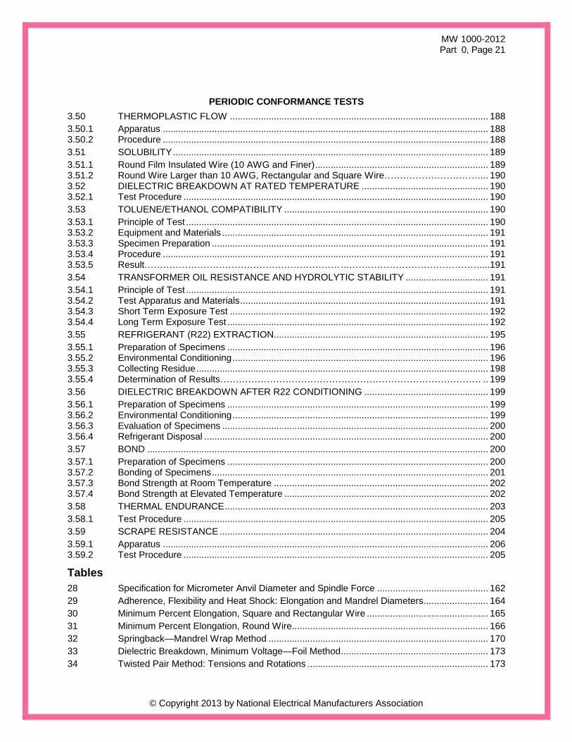
PERIODIC CONFORMANCE TESTS
3.50 THERMOPLASTIC FLOW .................................................................................................... 188
3.50.1 Apparatus .............................................................................................................................. 188 3.50.2 Procedure .............................................................................................................................. 188
3.51 SOLUBILITY .......................................................................................................................... 189
3.51.1 Round Film Insulated Wire (10 AWG and Finer) ................................................................... 189 3.51.2 Round Wire Larger than 10 AWG, Rectangular and Square Wire…………………………. ... 190 3.52 DIELECTRIC BREAKDOWN AT RATED TEMPERATURE ................................................. 190 3.52.1 Test Procedure ...................................................................................................................... 190
3.53 TOLUENE/ETHANOL COMPATIBILITY ............................................................................... 190
3.53.1 Principle of Test ..................................................................................................................... 190 3.53.2 Equipment and Materials ....................................................................................................... 191 3.53.3 Specimen Preparation ........................................................................................................... 191 3.53.4 Procedure .............................................................................................................................. 191 3.53.5 Result……………………………………………………… ... ……………………………………....191
3.54 TRANSFORMER OIL RESISTANCE AND HYDROLYTIC STABILITY ................................ 191
3.54.1 Principle of Test ..................................................................................................................... 191 3.54.2 Test Apparatus and Materials ................................................................................................ 191 3.54.3 Short Term Exposure Test .................................................................................................... 192 3.54.4 Long Term Exposure Test ..................................................................................................... 192
3.55 REFRIGERANT (R22) EXTRACTION................................................................................... 195
3.55.1 Preparation of Specimens ..................................................................................................... 196 3.55.2 Environmental Conditioning ................................................................................................... 196 3.55.3 Collecting Residue ................................................................................................................. 198 3.55.4 Determination of Results………………………………………………………………………… .. 199
3.56 DIELECTRIC BREAKDOWN AFTER R22 CONDITIONING ................................................ 199
3.56.1 Preparation of Specimens ..................................................................................................... 199 3.56.2 Environmental Conditioning ................................................................................................... 199 3.56.3 Evaluation of Specimens ....................................................................................................... 200 3.56.4 Refrigerant Disposal .............................................................................................................. 200
3.57 BOND .................................................................................................................................... 200
3.57.1 Preparation of Specimens ..................................................................................................... 200 3.57.2 Bonding of Specimens ........................................................................................................... 201 3.57.3 Bond Strength at Room Temperature ................................................................................... 202 3.57.4 Bond Strength at Elevated Temperature ............................................................................... 202
3.58 THERMAL ENDURANCE ...................................................................................................... 203
3.58.1 Test Procedure ...................................................................................................................... 205
3.59 SCRAPE RESISTANCE ........................................................................................................ 204
3.59.1 Apparatus .............................................................................................................................. 206 3.59.2 Test Procedure ...................................................................................................................... 205
Tables
28 Specification for Micrometer Anvil Diameter and Spindle Force ........................................... 162
29 Adherence, Flexibility and Heat Shock: Elongation and Mandrel Diameters ......................... 164
30 Minimum Percent Elongation, Square and Rectangular Wire ............................................... 165
31 Minimum Percent Elongation, Round Wire............................................................................ 166
32 Springback—Mandrel Wrap Method ..................................................................................... 170
33 Dielectric Breakdown, Minimum Voltage—Foil Method ......................................................... 173
34 Twisted Pair Method: Tensions and Rotations ...................................................................... 173

MW 1000-2012 Part 0, Page 22
© Copyright 2013 by National Electrical Manufacturers Association
35 Minimum Dielectric Breakdown Voltage—Twisted Pair Method ............................................ 174
36 Bend Method Mandrel Sizes .................................................................................................. 175
37 Rate of Increase in Voltage—Cylinder Method ...................................................................... 176
38 Cylinder Method Test Loads .................................................................................................. 177
39 Minimum Dielectric Breakdown Voltage—Cylinder Method .................................................. 177
40 Dielectric Breakdown, Film Insulated Rectangular and Square Magnet Wire ....................... 178
41 Test Voltages (DC Volts ±5%) and Maximum Fault Count Per 100 Feet ................................. 179
42 Test Voltages (DC Volts ±5%) and Maximum Fault Count per 100 Feet .............................. 181
43 Low-Voltage Continuity—Maximum Fault Count per 100 Feet .............................................. 182
44 Maximum Solder Immersion Times ....................................................................................... 186
45 Thermoplastic Flow Test Loads ............................................................................................. 189
46 Quantity of Specimens for Short Term Exposure Test .......................................................... 193
47 Pressure Vessel Components ............................................................................................... 193
48 Test Specimen Lengths and Weights for Long Term Exposure Test ................................... 194
49 Recommended Turns/Coil ..................................................................................................... 196
50 Typical Siphon Cup Dimensions ............................................................................................ 197
51 Bond Test Parameters ........................................................................................................... 199
52 Standard Scrape Resistance of Round Film Insulated Magnet Wire .................................... 205
53 Reduced Scrape Resistance of Round Film Insulated Magnet Wire .................................... 206
54 Scrape Resistance of Round Film Insulated Magnet Wire .................................................... 206
FIGURES
3-7-1-1 DETAILS OF SPRINGBACK SCALE ................................................................................... 168
3-7-1-2 SPRINGBACK TESTER AFTER WINDING A COIL UNDER TENSION ............................. 169
3-7-1-3 EXAMPLE OF SPRINGBACK SCALES ............................................................................... 169
3-7-2 APPARATUS FOR SPRINGBACK DEFLECTION METHOD .............................................. 171
3-8-4 WOUND PAIR SPECIMEN WINDER .................................................................................... 175
3-8-7 TEST APPARATUS FOR CYLINDER METHOD .................................................................. 176
3-9-1-1 EXAMPLE GRAPHITE BRUSH HOLDER ............................................................................ 180
3-9-1-2 ELECTRODE WITH GRAPHITE BRUSHES IN PLACE ...................................................... 180
3-9-3 BATH OF MERCURY OR OTHER SUITABLE MATERIAL ................................................. 182
3-10-2 ELECTRODE AND SPECIMEN ARRANGEMENT FOR DISSIPATION FACTOR TEST .... 183
3-13-3 SOLDERABILITY TEST SPECIMEN FIXTURE ................................................................... 188
3-51-1 MACHINE FOR SOLUBILITY SCRAPE ............................................................................... 189
3-55-1 REFRIGERANT EXTRACTABLE SIPHON CUP .................................................................. 197
3-55-2 CONDENSER COIL .............................................................................................................. 198
3-55-3 CONDENSER COIL SIPHON CUP ASSEMBLY .................................................................. 198
3-57-1 BOND COIL PREP FIXTURE ............................................................................................... 200
3-57-3-1 BOND STRENGTH TEST FIXTURE .................................................................................... 202
3-57-3-2 BOND TEST FIXTURE ......................................................................................................... 202
3-59-1 MACHINE FOR SCRAPE RESISTANCE ............................................................................. 204

MW 1000-2012 Part 0, Page 23
© Copyright 2013 by National Electrical Manufacturers Association
APPENDICES
A REFERENCE TEST CONDITIONS AND PROCEDURES FOR FILM-INSULATED
MAGNET WIRE ..................................................................................................................... A–1
B MAGNET WIRE PACKAGING AND LABELING .................................................................. B–1
C CROSS REFERENCE OF NEMA AND IEC MAGNET WIRE SPECIFICATIONS ............... C–1
D FORMULAS FOR THE DETERMINATION OF DIMENSIONAL AND PERFORMANCE
REQUIREMENTS .................................................................................................................. D–1
E GENERAL RULES FOR RECTANGULAR WIRE DIMENSIONS ........................................ E–1
F PROPERTIES OF SELECTED REFRIGERANTS ................................................................ F–1
G RECOMMENDED WINDING TENSIONS FOR ROUND COPPER AND ALUMINUM
FILM INSULATED MAGNET WIRE ..................................................................................... G–1

MW 1000-2012 Part 0, Page 24
© Copyright 2013 by National Electrical Manufacturers Association
FOREWORD
ANSI/NEMA MW 1000-2012 supersedes NEMA MW 1000-2008, Revision 1-2009, Revision 2-2010 and
MW 1000-2011. It has been approved as an American National Standard.
The standards contained in this publication are periodically reviewed by the NEMA Magnet Wire Section
for revisions considered to be necessary to keep them up to date with changes in technology. Proposed
or recommended revisions should be submitted to:
Senior Vice President, Operations
National Electrical Manufacturers Association
1300 North 17th Street
Rosslyn, Virginia 22209
These standards were developed by the Magnet Wire Section of NEMA, working closely with
representatives of various industries that use magnet wire. At the time they were approved, the Magnet
Wire Section had the following members:
Bridgeport Insulated Wire Company Bridgeport, CT
CONDUMEX México, D.F. Elektrisola, Inc. Boscawen, NH
Essex Group, Inc. Fort Wayne, IN
Magnekon San Nicolas, NL, Mexico
MWS Wire Industries Westlake Village, CA
Rea Magnet Wire Company, Inc. Fort Wayne, IN
Rubadue Wire Company, Inc. Greeley, CO
MW 1000-2012 Part 0, Page 25
© Copyright 2013 by National Electrical Manufacturers Association
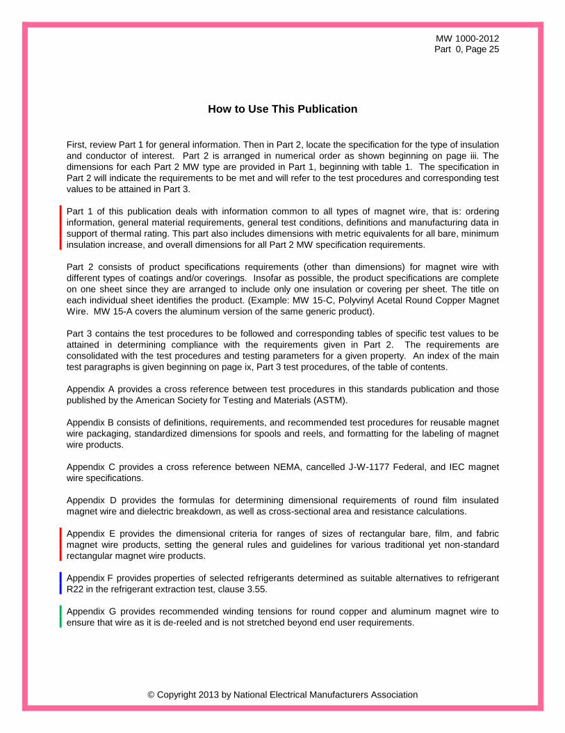
How to Use This Publication
First, review Part 1 for general information. Then in Part 2, locate the specification for the type of insulation
and conductor of interest. Part 2 is arranged in numerical order as shown beginning on page iii. The
dimensions for each Part 2 MW type are provided in Part 1, beginning with table 1. The specification in
Part 2 will indicate the requirements to be met and will refer to the test procedures and corresponding test
values to be attained in Part 3.
Part 1 of this publication deals with information common to all types of magnet wire, that is: ordering
information, general material requirements, general test conditions, definitions and manufacturing data in
support of thermal rating. This part also includes dimensions with metric equivalents for all bare, minimum
insulation increase, and overall dimensions for all Part 2 MW specification requirements.
Part 2 consists of product specifications requirements (other than dimensions) for magnet wire with
different types of coatings and/or coverings. Insofar as possible, the product specifications are complete
on one sheet since they are arranged to include only one insulation or covering per sheet. The title on
each individual sheet identifies the product. (Example: MW 15-C, Polyvinyl Acetal Round Copper Magnet
Wire. MW 15-A covers the aluminum version of the same generic product).
Part 3 contains the test procedures to be followed and corresponding tables of specific test values to be
attained in determining compliance with the requirements given in Part 2. The requirements are
consolidated with the test procedures and testing parameters for a given property. An index of the main
test paragraphs is given beginning on page ix, Part 3 test procedures, of the table of contents.
Appendix A provides a cross reference between test procedures in this standards publication and those
published by the American Society for Testing and Materials (ASTM).
Appendix B consists of definitions, requirements, and recommended test procedures for reusable magnet
wire packaging, standardized dimensions for spools and reels, and formatting for the labeling of magnet
wire products.
Appendix C provides a cross reference between NEMA, cancelled J-W-1177 Federal, and IEC magnet
wire specifications.
Appendix D provides the formulas for determining dimensional requirements of round film insulated
magnet wire and dielectric breakdown, as well as cross-sectional area and resistance calculations.
Appendix E provides the dimensional criteria for ranges of sizes of rectangular bare, film, and fabric
magnet wire products, setting the general rules and guidelines for various traditional yet non-standard
rectangular magnet wire products.
Appendix F provides properties of selected refrigerants determined as suitable alternatives to refrigerant
R22 in the refrigerant extraction test, clause 3.55.
Appendix G provides recommended winding tensions for round copper and aluminum magnet wire to
ensure that wire as it is de-reeled and is not stretched beyond end user requirements.

MW 1000-2012 Part 0, Page 26
© Copyright 2013 by National Electrical Manufacturers Association
<This Page Intentionally Left Blank.>

MW 1000-2012 Part 1, Page 27
© Copyright 2013 by the National Electrical Manufacturers Association
Part 1
GENERAL
1.1 SCOPE
This publication is designed to present in concise and convenient form all existing NEMA standards for magnet wire. It contains standards for round, rectangular, and square film insulated and/or fibrous covered copper and aluminum magnet wire for use in electrical apparatus. Included are the definitions, type designations, dimensions, constructions, performance, and test methods for magnet wire generally used in the winding of coils for electrical apparatus. Unless otherwise stated, a revision to a product specification in this standards publication does not affect compliance of product manufactured during the time a previous version of that specification was in effect. 1.2 NORMATIVE REFERENCES AND AUTHORIZED ENGINEERING INFORMATION (AEI)
The following references apply to parts 1, 2, and 3 only. Reference is made to the current revision of each of the standards or Authorized Engineering Information (AEI) listed below:
American Society for Testing Materials
100 Barr Harbor Drive
West Conshohocken, PA 19428 ASTM B 193 Standard Test Method for Resistivity of Electrical Conductor Materials ASTM B 3 Standard Specification for Soft or Annealed Copper Wire ASTM B 32 Standard Specification for Solder Metal ASTM B 48 Standard Specification for Soft Rectangular and Square Bare Copper Wire for
Electrical Conductors ASTM D 149 Standard Test Method for Dielectric Breakdown Voltage and Dielectric Strength of Solid Electrical Insulating Materials at Commercial Power Frequencies ASTM D 1676 Standard Methods for Testing Film-Insulated Magnet Wire ASTM D 1711 Standard Terminology Relating to Electrical Insulation ASTM D 1932 Standard Test Method for Thermal Endurance of Flexible Electrical Insulating Varnishes ASTM D 2307 Standard Test Method for Relative Thermal Endurance of Film-Insulated
Round Magnet Wire ASTM D 3353 Standard Methods for Testing Fibrous-Insulated Magnet Wire ASTM D 5423 Standard Specification for Forced-Convection Laboratory Ovens for Evaluation of
Electrical Insulation ASTM E 29 Standard Recommended Practice for Indicating Which Places of Figures Are
to Be Considered Significant in Specified Limiting Values ASTM E 8 Standard Methods of Tension Testing of Metallic Materials
International Electrotechnical Commission
3, rue de Varembé
Case postale 131
CH-1211 Geneva 20 IEC 60317-0-1 Specifications for particular types of winding wires-Part 0-1
General requirements-Enamelled round copper wire IEC 60317-0-2 Specifications for particular types of winding wires - Part 0-2 General requirements-Enamelled rectangular copper wire
Institute of Electrical and Electronics Engineers


![[ ANSI C37.20 and NEMA SG-5 ] - tekhar.comtekhar.com/Programma/HYUNDAI/pdf_pict/Ships_pruduction/KRU/Metal... · •ANSI C37.20.2 •NEMA SG-5 •IEEE Typical 4.76 kV and 15 kV Switchgear](https://static.fdocuments.us/doc/165x107/5ad9313a7f8b9ab8378e5319/-ansi-c3720-and-nema-sg-5-ansi-c37202-nema-sg-5-ieee-typical-476.jpg)


