ANSI EIAITIA-232-E Interface Standard
22
In this report: Mechanical Characteristics .......•........•... 2 Channels ......•........•.........•... 4 Interchange Circuits .... •...... • 4 Standard Interfaces for Selected Configurations ...•.. 7 Note: The content of this report has been revised and revalidated. It is be- ing published with a new date to indicate that the infonnation is current. DATA PRO Data Networking 2741 Standards 1 ANSI EIAITIA-232-E Interface Standard Datapro Summary ANSI EIAfTIA-232-E is the revision ofEIA-232-D (1986). The standard, approved in July 1991, is a set of specifications that applies to the transfer of data between data terminal equipment (DTE) and data circuit-terminating equipment (DCE). It defines the interface circuit functions and their corresponding connector pin assignments. The updated standard also includes specifications for a smaller alternative (26-pin) connector. Full- or half -duplex operations are supported for synchronous or asynchronous transmissions at speeds up to 20K bps. For data rates above 20K bps, ANSI EIAfTIA-530-A is the recommended standard. Copies of EIAfTIA-232-E can be obtained from the Electronic Industries Association, En- gineering Department, 2001 I Street NW, Washington, DC 20006. Analysis The ANSI Electronic Industries Association (EIA) Standard EIAffIA-232-E (simply EIA- 232-E, hereafter) is the July 1991 revision of EIA-232-D (1986). The revision comprises the ,following changes: • Specification for alternative interface connec- tor (AltA). • Addition of Circuit CJ (Ready for Receiving). • Use of Circuit CB (Clear to Send) for hard- ware flow control. • Use of Local Loopback for "Busy oue • Slight modifications to Circuits CE (Ring In- dicator) and CC (DCE Ready). None of the changes create compatibility prob- lems with any previous version of EIAffIA-232. EIA-232-E also confonns to the following inter- national standards: CCITI V.24 and V.28; EIA! TIA TSB-24 and TSB-26; and ISO IS211O. EIA-232-E applies to all classes of service: private line, dial-up, point-to-point, multipoint, switched, nonswitched, two-wire, and four-wire service. Asynchronous and synchronous data transmission is supported at speeds up to 20K bps in full- or half-duplex mode. EIA-232-E is a single-ended or unbalanced interface; all of the interchange signals share a common electrical ground. EIA-232-E defines the electrical and me- chanical characteristics of the interface for con- necting data tenninal equipment and data cir- cuit-tenninating equipment using serial binary data communications. As the tenns relate to this interface, DTE comprises business machine hardware such as teleprinters, CRTs, front-end processors, and CPUs, while DCE includes hardware such as modems, CSUIDSUs, limited distance data sets, and multiplexers. Electrical Characteristics The EIA-232-E standard prescribes polar-volt- age serial data transmission between communi- cating devices. On data interchange circuits, transmitted data is represented by the "Marking" condition for binary one and the "Spacing" con- dition for binary zero. A data signal on an inter- change circuit is in the Marking condition when the voltage at the interface point is more nega- tive than -3 volts with respect to Signal Ground (Circuit AB). When the data signal at the inter- face point is more positive than +3 volts, with respect to Signal Ground, the data signal is in the Spacing condition. The area between -3 and +3 volts is the transition region; the signal state is not defined in the transition region. On timing or control interchange circuits, the function is considered OFF when the voltage at the interface point is more negative than -3 volts, with respect to Signal Ground. It is considered C January 1995 McGraw-Hili, Incorporated. Reproduction Prohibited. Datapro Information ServIces Group. Delran NJ 08075 USA
Transcript of ANSI EIAITIA-232-E Interface Standard

In this report:
Mechanical Characteristics .......•........•... 2
Channels ......•........•.........•... 4
Interchange Circuits ....•......• 4
Standard Interfaces for Selected Configurations ...•.. 7
Note: The content of this report has been revised and revalidated. It is being published with a new date to indicate that the infonnation is current.
DATA PRO Data Networking 2741 Standards
1
ANSI EIAITIA-232-E Interface Standard
Datapro Summary
ANSI EIAfTIA-232-E is the revision ofEIA-232-D (1986). The standard, approved in July 1991, is a set of specifications that applies to the transfer of data between data terminal equipment (DTE) and data circuit-terminating equipment (DCE). It defines the interface circuit functions and their corresponding connector pin assignments. The updated standard also includes specifications for a smaller alternative (26-pin) connector. Full- or half -duplex operations are supported for synchronous or asynchronous transmissions at speeds up to 20K bps. For data rates above 20K bps, ANSI EIAfTIA-530-A is the recommended standard. Copies of EIAfTIA-232-E can be obtained from the Electronic Industries Association, Engineering Department, 2001 I Street NW, Washington, DC 20006.
Analysis The ANSI Electronic Industries Association (EIA) Standard EIAffIA-232-E (simply EIA-232-E, hereafter) is the July 1991 revision of EIA-232-D (1986). The revision comprises the ,following changes:
• Specification for alternative interface connector (AltA).
• Addition of Circuit CJ (Ready for Receiving).
• Use of Circuit CB (Clear to Send) for hardware flow control.
• Use of Local Loopback for "Busy oue
• Slight modifications to Circuits CE (Ring Indicator) and CC (DCE Ready).
None of the changes create compatibility problems with any previous version of EIAffIA-232. EIA-232-E also confonns to the following international standards: CCITI V.24 and V.28; EIA! TIA TSB-24 and TSB-26; and ISO IS211O.
EIA-232-E applies to all classes of service: private line, dial-up, point-to-point, multipoint, switched, nonswitched, two-wire, and four-wire service. Asynchronous and synchronous data transmission is supported at speeds up to 20K bps in full- or half-duplex mode. EIA-232-E is a single-ended or unbalanced interface; all of the interchange signals share a common electrical ground.
EIA-232-E defines the electrical and mechanical characteristics of the interface for connecting data tenninal equipment and data circuit-tenninating equipment using serial binary data communications. As the tenns relate to this interface, DTE comprises business machine hardware such as teleprinters, CRTs, front-end processors, and CPUs, while DCE includes hardware such as modems, CSUIDSUs, limited distance data sets, and multiplexers.
Electrical Characteristics The EIA-232-E standard prescribes polar-voltage serial data transmission between communicating devices. On data interchange circuits, transmitted data is represented by the "Marking" condition for binary one and the "Spacing" condition for binary zero. A data signal on an interchange circuit is in the Marking condition when the voltage at the interface point is more negative than -3 volts with respect to Signal Ground (Circuit AB). When the data signal at the interface point is more positive than +3 volts, with respect to Signal Ground, the data signal is in the Spacing condition. The area between -3 and +3 volts is the transition region; the signal state is not defined in the transition region.
On timing or control interchange circuits, the function is considered OFF when the voltage at the interface point is more negative than -3 volts, with respect to Signal Ground. It is considered
C January 1995 McGraw-Hili, Incorporated. Reproduction Prohibited. Datapro Information ServIces Group. Delran NJ 08075 USA
2 2741 Standards
Interchange Circuit Sample
Notation
Binary State
Signal Condition
Function
Interchange Voltage
Negative
Marking
OFF
ON if the voltage at the interface point is more positive than +3 volts, with respect to Signal Ground. The function is not defined for voltages in the transition region between -3 and +3 volts. See Table "Interchange Circuit Sample."
Mandatory Interchange Circuit conditions are as follows (see Figure "Electrical Interchange Circuit Characteristics"):
• Open circuit generator voltage, with respect to Signal Ground, must not exceed 25 volts with respect to ground.
• The potential at the interface point must not be less than 5 volts nor more than 15 volts in magnitude when the receiver resistance is between 3000 and 7000 ohms, and the receiver open voltage is O.
• The effective shunt capacitance associated with the receiver must not exceed 2500 picofarads at the interface point.
• The open circuit receiver voltage must not exceed 2 volts.
• Request to Send (Circuit CA), DCE Ready (Circuit CC), DTE Ready (Circuit CD), and Secondary Request to Send (Circuit SCA), where implemented, are used to detect the power-off condition or the disconnection of the interconnecting cable.
Certain limitations apply to all interchange signals (data, control, and timing) as follows:
• Interchange signals entering transition must proceed to the opposite signal state, and may not reenter the transition region until the next significant change in signal condition.
Figure Eketrklllinterelumge Cireuit C1uJrGe'eri.tie.
GENERATOR
ANSI EIA/TIA-23Z,E Interface Standard
Positive
0
Spacing
ON
Data Networking
• The direction of voltage must not change while in the transition region.
• The time required for a control signal to pass through the transition region must not exceed one millisecond.
• The time required for a data or timing signal to pass through the transition region must not exceed one millisecond or 4% of the normal duration of a signal element on that interchange circuit, whichever is the lesser.
• The maximum instantaneous rate of voltage must not exceed 30 volts per microsecond.
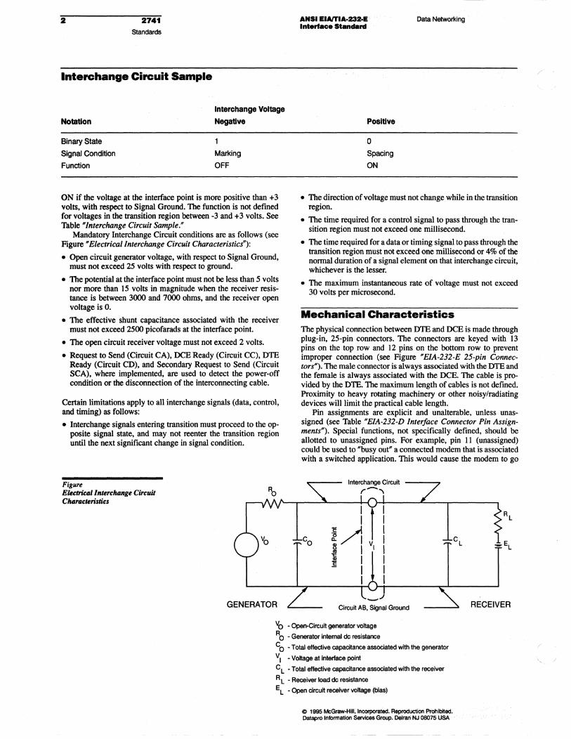
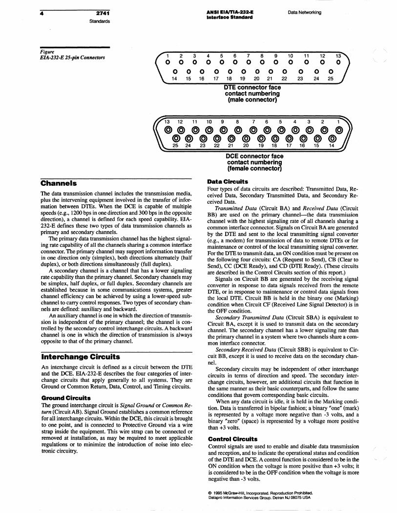
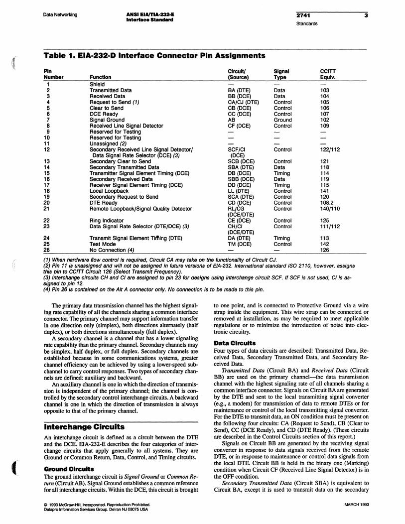
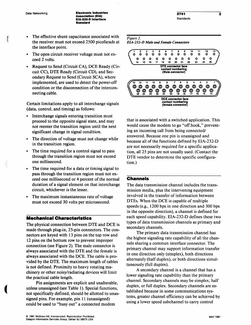
Mechanical Characteristics The physical connection between DTE and DCE is made through plug-in, 25-pin connectors. The connectors are keyed with 13 pins on the top row and 12 pins on the bottom row to prevent improper connection (see Figure HEIA-232-E 25-pin Connectors"). The male connector is always associated with the DTE and the female is always associated with the DCE. The cable is provided by the DTE. The maximum length of cables is not defined. Proximity to heavy rotating machinery or other noisy/radiating devices will limit the practical cable length.
Pin assignments are explicit and unalterable, unless unassigned (see Table "EIA-232-D Interface Connector Pin Assignments"). Special functions, not specifically defined, should be allotted to unassigned pins. For example, pin 11 (unassigned) could be used to "busy out" a connected modem that is associated with a switched application. This would cause the modem to go
I I
~ ~ Q. /' I ~ I ~ I - I
I
Circuit AB, Signal Ground RECEIVER
Vo -Open-Circuit generator voltage
RO - Generator internal de resistance
Co - Total effective capacitance associated with the generator
VI - Voltage at Interface point
C L - Total effective capacitance assooiatecJ with the receiver
R L - Receiver load de resistance
EL - Open circuit receiver voltage (bias)
C 1995 McGraw-HiU, InCOlpOrat8d. Reproductron Pl'ohibited. Dalepro Inionnation Services Group. Delran·NJ 08075 USA .'
if \ '~. ,
(
Data Networking ANSI EIAlTIa,,232-E Int ..... e. Standard
EIA.232-D Interface Connector Pin Assignments
Pin Number Function Circuit (Source)
Shield
2 Transmitted Data BA(DTE)
3 Received Data BB (DCE)
4 Request to Send (1) CAlCJ (DTE)
5 Clear to Send CB(DCE)
6 DCE Ready CC (DC E)
7 Signal Ground AB
8 Received Une Signal CF (DCE) Detector
9 Reserved for Testing
10 Reserved for Testing
11 Unassigned (2)
12 Secondary Received Une SCF/CI (DCE) Signal DetectorlData Signal Rate Selector (DCE) (3)
13 Secondary Clear to Send SCB (DCE)
14 Secondary Transmitted SBA(DTE) Data
15 Transmitter Signal DB (DCE) Element Timing (DCE)
16 Secondary Received Data SBB (DCE)
17 Receiver Signal Element DO (DCE) Timing (DCE)
18 Local Loopback LL(DTE)
19 Secondary Request to SCA(DTE) Send
20 DTEReady CD (DCE)
21 Remote Loopback/Signal RLlCG (DCE/DTE) Quality Detector
22 Ring Indicator CE (DCE)
23 Data Signal Rate Selector CHICI (DCE/DTE) (DTE/DCE) (3)
24 Transmit Signal Element DA(DTE) Timing (DTE)
25 Test Mode TM (DCE)
26 No Connection (4)
Signal Type
Data
Data
Control
Control
Control
Ground
Control
Control
Control
Data
Timing
Data
Timing
Control
Control
Control
Control
Control
Control
Timing
Control
(1) When hardware flow control is required, Circuit CA may take on the functionality of Circuit CJ.
274t Standards
CCITT Equlv.
103 104 105 106 107 102 109
1221112
121 118
114
119 115
141 120
108.2 140/110
125 111/112
113
142 126
(2) Pin 11 is assigned and will not be assigned in future versions of EIA-232.lntemational standard ISO 2110, however, assigns this pin to CCITT Circuit 126 (Select Transmit Frequency).
3
(3) Interchange circuits CH and CI are asSigned to pin 23 for designs using interchange circuit SCF. If SCF is not used, CI is assigned to pin 12.
(4) Pin 26 is contained on the Aft A connector only. No connection is to be made to this pin.
"off hook,' preventing an incoming call from being connected! answered. Because one pin is unassigned and because all of the functions defined by EIA-232-E are not necessarily required for a specific application, all 25 pins are not usually used. (Contact the DTE vendor to determine the specific configuration.)
o 1996 McGraw-Hill. IIICOIJlOI1IIed. Reproduction Prohibited. DaIapro Information Services Group. Delran NJ 08075 USA
Although the 25-pin version is still the most popular connec-tor, EIA-232-E provides for an alternative physical interface (Alt A) for applications requiring a smaller connector. At about %" wide, the Alt A connector is about half the size of the 25-pin version.
4
Figure
2741 Standards
EIA·232·E 25·pin Connectors 1 0
0 14
2 3 0 0
0 0 15 16
ANSI EIAlTIA-232-E Interface Slandard
4 5 6 7 8 9 0 0 0 0 0 0
0 0 0 0 0 17 18 19 20 21
OlE connector face contact numbering (male connector)
Data Networking
10 11 12 13 0 0 0 0
0 0 0 0 22 23 24 25
13 12 11 10 9 8 7 6 5 4 3 2
OOO(O)OOOO(O)@@O @@OOO@@OOOO 25 24 23 22 21 20 19 18 17 16 15
. Channels The data transmission channel includes the transmission media, plus the intervening equipment involved in the transfer of infor· mation between DTEs. When the DCE is capable of multiple speeds (e.g., 1200 bps in one direction and 300 bps in the opposite direction), a channel is defmed for each speed capability. EIA-232-E defines these two types of data transmission channels as primary and secondary channels.
The primary data transmission channel has the highest signaling rate capability of all the channels sharing a common interface connector. The primary channel may support information transfer in one direction only (simplex), both directions alternately (half duplex), or both directions simultaneously (full duplex).
A secondary channel is a channel that has a lower signaling rate capability than the primary channel. Secondary channels may be simplex, half duplex, or full duplex. Secondary channels are established because in some communications systems, greater channel efficiency can be achieved by using a lower-speed subchannel to carry control responses. Two types of secondary channels are defined: auxiliary and backward.
An auxiliary channel is one in which the direction of transmission is independent of the primary channel; the channel is controlled by the secondary control interchange circuits. A backward channel is one in which the direction of transmission is always opposite to that of the primary channel.
Interchange Circuits An interchange circuit is defined as a circuit between the DTE and the DCE. EIA-232-E describes the four categories of interchange circuits that apply generally to all systems. They are Ground or Common Return, Data, Control, and TIming circuits.
Ground Circuits The ground interchange circuit is Signal Ground or Common Re· turn (Circuit AB). Signal Ground establishes a common reference for all interchange circuits. Within the DCE, this circuit is brought to one point, and is connected to Protective Ground via a wire strap inside the equipment. This wire strap can be connected or removed at installation, as may be required to meet applicable regulations or to minimize the introduction of noise into electronic circuitry.
DeE connector face contact numbering (female connector)
Data Circuits Four types of data circuits are described: Transmitted Data, Received Data, Secondary Transmitted Data, and Secondary Received Data.
Transmitted Data (Circuit BA) and Received Data (Circuit BB) are used on the primary channel-the data transmission channel with the highest signaling rate of all channels sharing a common interface connector. Signals on Circuit BA are generated by the DTE and sent to the local transmitting signal converter (e.g., a modem) for transmission of data to remote DTEs or for maintenance or control of the local transmitting signal converter. For the DTE to transmit data, an ON condition must be present on the following four circuits: CA (Request to Send), CB (Clear to Send), CC (DCE Ready), and CD (DTE Ready). (These circuits are described in the Control Circuits section of this report.)
Signals on Circuit BB are generated by the receiving signal converter in response to data signals received from the remote DTE, or in response to maintenance or control data signals from the local DTE. Circuit BB is held in the binary one (Marking) condition when Circuit CF (Received Line Signal Detector) is in the OFF condition.
Secondary Transmitted Data (Circuit SBA) is equivalent to Circuit BA, except it is used to transmit data on the secondary channel. The secondary channel has a lower signaling rate than the primary channel in a system where two channels share a common interface connector.
Secondary Received Data (Circuit SBB) is equivalent to Circuit BB, except it is used to receive data on the secondary channel.
Secondary circuits may be independent of other interchange circuits in terms of direction and speed. The secondary interchange circuits, however, are additional circuits that function in the same manner as their basic counterparts, and follow the same conditions that govern corresponding basic circuits.
When any data circuit is idle, it is held in the Marking condition. Data is transferred in bipolar fashion; a binary "one" (mark) is represented by a voltage more negative than -3 volts, and a binary "zero" (space) is represented by a voltage more positive than +3 volts.
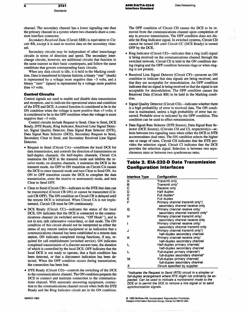
Control Circuits Control signals are used to enable and disable data transmission and reception, and to indicate the operational status and condition of the DTE and DCE. A control function is considered to be in the ON condition when the voltage is more positive than +3 volts; it is considered to be in the OFF condition when the voltage is more negative than -3 volts.
@ 1995 McGraw-Hili. Incorporated. Reproduction Prohibited. Dalapro Information Services Group. Delren NJ 08075 USA
(
Data Networking ANSI EIA/TIA·232-E Interface Standard
2741 Standards
5
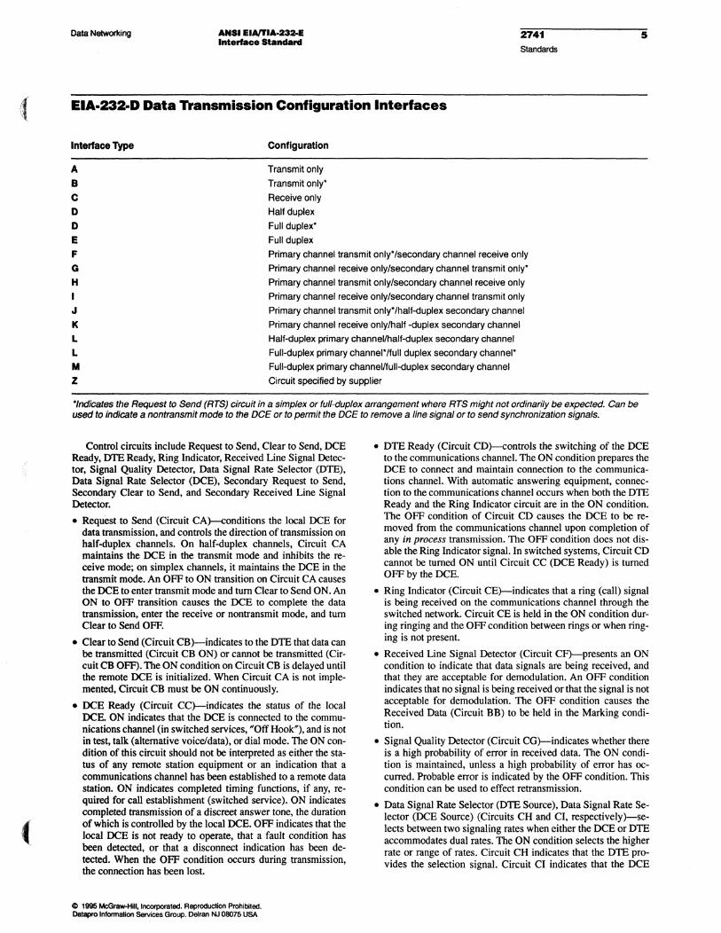
EIA.232-D Data Transmission Configuration Interfaces
Interface Type Configuration
Transmit only
Transmit only' Receive only Half duplex Full duplex' Full duplex
A B C D D E F G H I J K
L L M Z
Primary channel transmit only'/secondary channel receive only Primary channel receive only/secondary channel transmit only' Primary channel transmit only/secondary channel receive only Primary channel receive only/secondary channel transmit only Primary channel transmit only'thalf-duplex secondary channel Primary channel receive only/half -duplex secondary channel Half-duplex primary channellhalf-cluplex secondary channel Full-duplex primary channel'/full duplex secondary channel' Full-duplex primary channellfull-cluplex secondary channel Circuit specified by supplier
·'ndicates the Request to Send (RTS) circuit in a simplex or full-duplex arrangement where RTS might not ordinarily be expected. Can be used to indicate a nontransmit mode to the DCE or to permit the DCE to remove a line signal or to send synchronization signals.
Control circuits include Request to Send, Clear to Send, DCE Ready, DTE Ready, Ring Indicator, Received Line Signal Detector, Signal Quality Detector, Data Signal Rate Selector (DTE), Data Signal Rate Selector (DCE), Secondary Request to Send, Secondary Clear to Send, and Secondary Received Line Signal Detector.
• Request to Send (Circuit CA)-conditions the local DCE for data transmission, and controls the direction of transmission on half-duplex channels. On half-duplex channels, Circuit CA maintains the DCE in the transmit mode and inhibits the receive mode; on simplex channels, it maintains the DCE in the transmit mode. An OFF to ON transition on Circuit CA causes the DCE to enter transmit mode and tum Clear to Send ON. An ON to OFF transition causes the DCE to complete the data transmission, enter the receive or nontransmit mode, and tum Clear to Send OFF.
• Clear to Send (Circuit CB)-indicates to the DTE that data can be transmitted (Circuit CB ON) or cannot be transmitted (Circuit CB OFF). The ON condition on Circuit CB is delayed until the remote DCE is initialized. When Circuit CA is not implemented, Circuit CB must be ON continuously.
• DCE Ready (Circuit CC)-indicates the status of the local DCE. ON indicates that the DCE is connected to the communications channel (in switched services, HOff HookH), and is not in test, talk (alternative voice/data), or dial mode. The ON condition of this circuit should not be interpreted as either the status of any remote station equipment or an indication that a communications channel has been established to a remote data station. ON indicates completed timing functions, if any, required for call establishment (switched service). ON indicates completed transmission of a discreet answer tone, the duration of which is controlled by the local DCE. OFF indicates that the local DCE is not ready to operate, that a fault condition has been detected, or that a disconnect indication has been detected. When the OFF condition occurs during transmission, the connection has been lost.
o 1995 Mc:Graw-HiII, Incorporated. Reproduction Prohibited. Datapro Information SeMces Group. Delran NJ 08075 USA
• DTE Ready (Circuit CD)-controls the switching of the DCE to the communications channel. The ON condition prepares the DCE to connect and maintain connection to the communications channel. With automatic answering equipment, connection to the communications channel occurs when both the DTE Ready and the Ring Indicator circuit are in the ON condition. The OFF condition of Circuit CD causes the DCE to be removed from the communications channel upon completion of any in process transmission. The OFF condition does not disable the Ring Indicator signal. In switched systems, Circuit CD cannot be turned ON until Circuit CC (DCE Ready) is turned OFF by the DCE.
• Ring Indicator (Circuit CE)-indicates that a ring (call) signal is being received on the communications channel through the switched network. Circuit CE is held in the ON condition during ringing and the OFF condition between rings or when ringing is not present.
• Received Line Signal Detector (Circuit CF)-presents an ON condition to indicate that data signals are being received, and that they are acceptable for demodulation. An OFF condition indicates that no signal is being received or that the signal is not acceptable for demodulation. The OFF condition causes the Received Data (Circuit BB) to be held in the Marking condition.
• Signal Quality Detector (Circuit CG)-indicates whether there is a high probability of error in received data. The ON condition is maintained, unless a high probability of error has occurred. Probable error is indicated by the OFF condition. This condition can be used to effect retransmission.
• Data Signal Rate Selector (DTE Source), Data Signal Rate Selector (DCE Source) (Circuits CH and CI, respectively)-selects between two signaling rates when either the DCE or DTE accommodates dual rates. The ON condition selects the higher rate or range of rates. Circuit CH indicates that the DTE provides the selection signal. Circuit CI indicates that the DCE
• 2741 Standards
ANSI EIAITIA-232oE Interface Standard
Data Networking
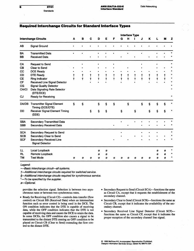
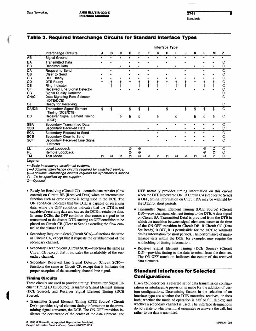
Required Interchange Circuits for Standard Interface Types
Interchange ·Clrcults A B C D
AB Signal Ground
BA Transmitted Data BB Received Data
CA Request to Send CB Clear to Send CC DCE Ready CD DTE Ready t t t t CE Ring Indicator t t t t CF Received Line Signal Detector CG Signal Quality Detector CHiCI Data Signaling Rate Selector
(DTElDCE) CJ Ready for Receiving
DAIDB Transmitter Signal Element § § § Timing (DCE/DTE)
DD Receiver Signal Element Timing § § (DDE)
SBA Secondary Transmitted Data SBB Secondary Received Data
SCA Secondary Request to Send SCB Secondary Clear to Send SCF Secondary Received Line
Signal Detector
LL Local Loopback " RL Remote Loopback " TM Test Mode " " f2I f2I
Legend: -Basic interchange circuit-all systems. t-Additional interchange circuits required for switched service. §-Additional interchange circuits required for synchronous service. o-To be specified by the supplier. e-Optional.
provides the selection signal. Selection is between two asyn-chronous rates or between two synchronous rates.
• Ready for Receiving (Circuit CJ}-controls data transfer (flow control) on Circuit BB (Received Data) when an intennediate function such as error control is being used in the DCE. The ON condition indicates that the DTE is capable of receiving data, while the OFF condition indicates that the DTE is not capable of receiving data and causes the DCE to retain the data. In some DCEs, the OFF condition also causes a signal to be transmitted to the distant DTE causing an OFF condition to be placed on Circuit CB (Clear to Send) extending the flow con-trol to the distant DTE.
Interface Type E F G H I J K L M Z
0
0
0
0
0
t t t t t t t t t 0
t t t t t t t t t 0
0
0
0
0
§ § § § § § § 0
§ § § § § § 0
0
0
0
0
0
" " " 0
" " " 0
f2I f2I f2I f2I f2I f2I f2I f2I f2I 0
• Secondary Request to Send (Circuit SCA}-functions the same as Circuit CA, except that it requests the establishment of the secondary channel.
• Secondary Clear to Send (Circuit SCB}-functions the same as Circuit CB, except that it indicates the availability of the sec-ondary channel.
• Secondary Received Line Signal Detector (Circuit SCF)-functions the same as Circuit CF, except that it indicates the proper reception of the secondary channel line signal.
C 1995 Ml:GraW'-Hili. Incorporated. Reproduction Prohibited. Datspro information Services Group. Delran NJ 0lI07$ USA
/ " /

(
Data Networking
Timing Circuits
ANSI EIAI1'IA-232-E Interlace Stand8rd
Three circuits are used to provide timing: Transmitter Signal Element TIming (DTE Source), Transmitter Signal Element Timing (DCE Source), and Receiver Signal Element Timing (DCE Source).
• Transmitter Signal Element Timing (DTE Source) (Circuit DAr-provides signal element timing information to the transmitting signal converter, the DCE. The ON-OFF transition indicates the occurrence of the center of the data element. The DTE normally provides timing information on this circuit when the DTE is powered ON. If Circuit CA (Request to Send) is OFF, timing information on Circuit DA may be withheld by the DTE for short periods.
• Transmitter Signal Element Timing (DCE Source) (Circuit DB)-provides signal element timing to the DTE. A data signal on Circuit BA (Transmitted Data) is provided from the DTE in which the transition between signal elements occurs at the time of the ON-QFF transition in Circuit DB. If Circuit CC (Data Set Ready) is OFF, it is permissible for the DCE to withhold timing information for short periods. The performance of maintenance tests within the DCE, for example, may require the withholding of timing information.
• Receiver Signal Element TIming (DCE Source) (Circuit DD)-provides timing to the data terminal from the data set. The ON-OFF transition indicates the center of the received data elements.
Standard Interfaces for Selected Configurations EIA-232-E describes a selected set of data transmission configurations or interfaces. A provision is made for the addition of custom configurations. Determining factors in the selection of an
o 1995 McGraw-Hill. Inc:otpOI'IIIed. Reproduction ProhlbIIed. Datapro InformaIIon Selvices Group. Delran NJ 08075 USA
2741 Standards
7
interface type are whether the DTE transmits, receives, or does both; whether the mode of operation is half or full duplex; and whether a secondary channel is used. The interface designations do not relate to which terminal originates or answers the call, but rather to the data transmitted.
EIA-232-E defines selected interface types by letter designation. These types are described in Table "EIA-232-D Data Transmission Configuration Interfaces," where the direction of data transfer pertaining to the interface is stated (function), and the use of Request to Send and Received Line Signal Detector interchange circuits is stipulated (comment). This list indicates that interfaces A and B, which are one-way only transmissions, differ only in terms of the use ofRTS. Interface D is normally employed with half-duplex operation using RTS, and interface E is normally employed with full-duplex operation, without using RTS. When interface D is used in full-duplex operation, however, RTS is used with special significance.
Interfaces E, P, 0, and H define two-way transmission where both the primary and secondary directions are one way only.
Interfaces J, K, L, and M define less restrictive primary and secondary arrangements.
Interface Z simply allows a special arrangement to be established.
The complete relationship of interchange circuits to standard interface types is depicted in Table "Required Interchange Circuits for Standard Inter/ace Types."


(
In this report:
Mechanical Characteristics •...................• 2
Channels ............•......•.....•.•.. 2
Interchange Circuits ................................. 3
Standard Interfaces for Selected Configurations .• 5
Note: This report on EIA-232-E replaces the report on EIA-232-D. The two interfaces are completely compatible, and the minor revisions contained in the updated standard are included in this report.
DATAPRO Data Networking 2741 Standards
1
ANSI EIAITIA-232-E Interface Standard
Datapro Summary
ANSI EIAfTIA-232-E is the revision ofEIA-232-D (1986). The standard, approved in July 1991, is a set of specifications that applies to the transfer of data between data tenninal equipment (DTE) and data circuit-tenninating equipment (DCE). It defines the interface circuit functions and their corresponding connector pin assignments. The updated standard also includes specifications for a smaller alternative (26-pin) connector. Full- or balf-duplex operations are supported for synchronous or asynchronous transmissions at speeds up to 20K bps. For data rates above 20K bps, ANSI EIAmA-530-A is the recommended standard. Copies of EIAfTIA-232-E can be obtained from the Electronic Industries Association, Engineering Department, 2001 I Street NW, Washington, DC 20006.
Analysis The ANSI Electronic Industries Association (EIA) Standard EIAlTIA-232-E (simply EIA-232-E, hereafter) is the July 1991 revision of EIA-232-D (1986). The revision comprises the following changes:
• Specification for alternative interface connector (AltA).
• Addition of Circuit CJ (Ready for Receiving).
• Use of Circuit CB (Clear to Send) for hardware flow control.
• Use of Local Loopback for "Busy Out."
• Slight modifications to Circuits CE (Ring Indicator) and CC (OCE Ready).
None of the changes create compatibility problems with any previous version of EIAlTIA-232. EIA-232-E also conforms to the following international standards: CCITI V.24 and V.28; EIN TIA TSB-24 and TSB-26; and ISO IS2110.
EIA-232-E applies to all classes of service: private line, dial-up, point-to-point, multipoint, switched, nonswitched, two-wire, and four-wire service. Asynchronous and synchronous data transmission is supported at speeds up to 20K
-By Vance Macdonald Research Analyst
bps in full- or half-duplex mode. EIA-232-E is a single-ended or unbalanced interface; all of the interchange signals share a common electrical ground.
EIA-232-E dermes the electrical and mechanical characteristics of the interface for connecting data terminal equipment and data circuit-terminating equipment using serial binary data communications. As the terms relate to this interface, DTE comprises business machine hardware such as teleprinters, CRTs, front-end processors, and CPUs, while OCE includes hardware such as modems, CSU/DSUs, limited distance data sets, and multiplexers.
Electrical Characteristics The EIA-232-E standard prescribes polar-voltage serial data transmission between communicating devices. On data interchange circuits, transmitted data is represented by the "Marking" condition for binary one and the "Spacing" condition for binary zero. A data signal on an interchange circuit is in the Marking condition when the voltage at the interface point is more negative than -3 volts with respect to Signal Ground (Circuit AB). When the data signal at the interface point is more positive than +3 volts, with respect to Signal Ground, the data
@ 1993 McGraw-Hili. Incorporated. Reproduction Prohibited. Oatapro Information Services Group. Delran NJ 08075 USA
MARCH 1993
2 2741 Standards
signal is in the Spacing condition. The area between -3 and +3 volts is the transition region; the signal state is not dermed in the transition region.
On timing or control interchange circuits, the function is considered OFF when the voltage at the interface point is more negative than -3 volts, with respect to Signal Ground. It is considered ON if the voltage at the interface point is more positive than +3 volts, with respect to Signal Ground. The function is not dermed for voltages in the transition region between -3 and +3 volts.
Interchange Voltage
Notation
Binary State
Signal Condition
Function
Negative
Marking
OFF
Positive
a Spacing
ON
Mandatory Interchange Circuit conditions are as follows (see figure 1):
• Open circuit generator voltage, with respect to Signal Ground, must not exceed 25 volts with respect to ground.
• The potential at the interface point must not be less than 5 volts nor more than 15 volts in magnitude when the receiver resistance is between 3000 and 7000 ohms, and the receiver open voltage is O.
• The effective shunt capacitance associated with the receiver must not exceed 2500 picofarads at the interface point.
• The open circuit receiver voltage must not exceed 2 volts.
• Request to Send (Circuit CA), DCE Ready (Circuit CC), DTE Ready (Circuit CD), and Secondary Request to Send (Circuit SCA), where implemented, are used to detect the power-off condition or the disconnection of the interconnecting cable.
Certain limitations apply to all interchange signals (data, control, and timing) as follows:
• Interchange signals entering transition must proceed to the opposite signal state, and may not reenter the transition region until the next significant change in signal condition.
• The direction of voltage must not change while in the transition region.
• The time required for a control signal to pass through the transition region must not exceed one millisecond.
• The time required for a data or timing signal to pass through the transition region must not exceed one millisecond or 4% of the nonnal duration of a signal element on that interchange circuit, whichever is the lesser.
• The maximum instantaneous rate of voltage must not exceed 30 volts per microsecond.
Mechanical Characteristics The physical connection between DTE and DCE is made through plug-in, 25-pin connectors. The connectors are keyed with 13 pins on the top row and 12 pins on the bottom row to prevent improper connection (see Figure 2). The male connector is always associated with the DTE and the female is always associated with the DCE. The cable is provided by the DTE. The maximum length of cables is not defined. Proximity to heavy rotating machinery or other noisy/radiating devices will limit the practical cable length.
MARCH 1993
ANSI EIA/TIA-23M Interface Standard
Data Networking
Figure 1. Electrkallntuclumge Circuit ChtllYlCteristks
~ - 0p0n-CIrcuit --"" voltage 'b -_In_de_ Co -Total_ve c:apaci1Bnce ___ the generator
VI - Voltage at In_ point cL - TOiaI elfaclivec:apaci1Bnce ___ the_ RL • __ de raoIotance
EL • Open oirouft receiver voltage (bias)
Pin assignments are explicit and unalterable, unless unassigned (see Table 1). Special functions, not specifically defined, should be allotted to unassigned pins. For example, pin 11 (unassigned) could be used to "busy out" a connected modem that is associated with a switched application. This would cause the modem to go "off hook," preventing an incoming call from being connected/answered. Because one pin is unassigned and because all of the functions defined by EIA-232-E are not necessarily required for a specific application, all 25 pins are not usually used. (Contact the DTE vendor to determine the specific configuration.)
Although the 25-pin version is still the most popular connector, EIA-232-E provides for an alternative physical interface (Alt A) for applications requiring a smaller connector. At about ~" wide, the Alt A connector is about half the size of the 25-pin version.
Channels The data transmission channel includes the transmission media, plus the intervening equipment involved in the transfer of information between DTEs. When the DCE is capable of multiple speeds (e.g., 1200 bps in one direction and 300 bps in the opposite direction), a channel is defined for each speed capability. EIA-232-E defines these two types of data transmission channels as primary and secondary channels.
Figure 2. EIA-232-E 25-pin Connectors
1 2 3 4 5 6 7 8 9 10 11 12 13 0000000000000 000000000000 14 15 16 17 18 19 20 21 22 23 24 25
DTE connector face contact numbering (Male connector)
13 12 11 10 9 8 7 6 5 4 3 2 1
@@@@@@@@@@@@@ @@@@@@@@@@@@ 25 24 23 22 21 20 19 18 17 16 15 14
DCE connector face contact numbering (female connector)
@ 1993 McGraw-Hill,lncorporaled. Reproduction Prohibited. Dalapro Information Services Group. Delran NJ 08075 USA
/ I
(
(
Data Networking ANSI IIA/TIA-Uz,E Interface StIIncIard
2741 Standards
3
Table 1. EIA·232·D Interface Connector Pin Assignments
Pin Circuit! Signal CCITT Number Function (Source) Type Equiv.
1 Shield 2 Transmitted Data BA (DTE) Data 103 3 Received Data BB (DCE) Data 104 4 Request to Send (1) CAfCJ (DTE) Control 105 5 Clear to Send ca (DCE) Control 106 6 DCE Ready CC (DCE) Control 107 7 Signal Ground AB Ground 102 8 Received Line Signal Detector CF (DCE) Control 109 9 Reserved for Testing
10 Reserved for Testing 11 Unassigned (2) 12 Secondary Received Line Signal Detector/ SCF/CI Control 122/112
Data Signal Rate Selector (DCE) (3) (DCE) 13 Secondary Clear to Send SCB (DCE) Control 121 14 Secondary Transmitted Data SBA (DTE) Data 118 15 Transmitter Signal Element Timing (DCE) DB (DCE) Timing 114 16 Secondary Received Data SBa (DCE) Data 119 17 Receiver Signal Element Timing (DCE) DO (DCE) Timing 115 18 Local Loopback LL (DTE) Control 141 19 Secondary Request to Send SCA (DTE) Control 120 20 DTE Ready CD (DCE) Control 108.2 21 Remote Loopback/Signal Quality Detector RL/CG Control 140/110
(DCE/DTE) 22 Ring Indicator CE (DCE) Control 125 23 Data Signal Rate Selector (DTE/DCE) (3) CH/CI Control 111/112
(DCE/DTE) 24 Transmit Signal Element Timing (DTE) DA (OTE) Timing 113 25 Test Mode TM (DCE) Control 142 26 No Connection (4) 126
(1) When hardware flow control is required, Circuit CA may take on the functionality of Circuit CJ. (2) Pin 11 is unassigned and will not be assigned In future versions of EIA-232. International standard ISO 2110, however, assigns this pin to CCITT Circuit 126 (Select Transmit Frequency). (3) Interchange circuits CH and CI are assigned to pin 23 for designs using interchange circuit SCF. If SCF is not used, CI is as-signed to pin 12. (4) Pin 26 is contained on the Alt A connector only. No connection is to be made to this pin.
The primary data transmission channel has the highest signaling rate capability of all the channels sharing a common interface connector. The primary channel may support information transfer in one direction only (simplex), both directions alternately (half duplex), or both directions simultaneously (full duplex).
A secondary channel is a channel that has a lower signaling rate capability than the primary channel. Secondary channels may be simplex, half duplex, or full duplex. Secondary channels are established because in some communications systems, greater channel efficiency can be achieved by using a lower-speed subchannel to carry control responses. 1\vo types of secondary channels are defined: auxiliary and backward.
An auxiliary channel is one in which the direction of transmission is independent of the primary channel; the channel is controlled by the secondary control interchange circuits. A backward channel is one in which the direction of transmission is always opposite to that of the primary channel.
Interchange Circuits An interchange circuit is defined as a circuit between the DTE and the OCE. EIA-232-E describes the four categories of interchange circuits that apply generally to all systems. They are Ground or Common Return, Data, Control, and Timing circuits.
Ground Circuits The ground interchange circuit is Signal Ground or Common Return (CircuitAB). Signal Ground establishes a common reference for all interchange Circuits. Within the DCE, this circuit is brought
«> 1993 McGraw-Hi1i. Incorpora1ed. Reproduction Prohibited. Datapro Information Services Group. Delran NJ 08075 USA
to one point. and is connected to Protective Ground via a wire strap inside the equipment. This wire strap can be connected or removed at installation, as may be required to meet applicable regulations or to minimize the introduction of noise into electronic circuitry.
Data Circuits Four types of data circuits are described: Transmitted Data. Received Data, Secondary Transmitted Data, and Secondary Received Data.
Transmitted Data (Circuit BA) and Received Data (Circuit BB) are used on the primary channel-the data transmission channel with the highest signaling rate of all channels sharing a common interface connector. Signals on Circuit BA are generated by the DTE and sent to the local transmitting signal converter (e.g., a modem) for transmission of data to remote DTEs or for maintenance or control of the local transmitting signal converter. For the DTE to transmit data, an ON condition must be present on the following four circuits: CA (Request to Send), CB (Clear to Send), CC (DCE Ready), and CD (DTE Ready). (These circuits are described in the Control Circuits section of this report.)
Signals on Circuit BB are generated by the receiving signal converter in response to data signals received from the remote DTE. or in response to maintenance or control data signals from the local DTE. Circuit BB is held in the binary one (Marking) condition when Circuit CF (Received Line Signal Detector) is in the OFF condition.
Secondary Transmitted Data (Circuit SBA) is equivalent to Circuit BA, except it is used to transmit data on the secondary
MARCH 1993
4 2741 Standards
channel. The secondary channel has a lower signaling rate than the primary channel in a system where two channels share a common interface connector.
Secondary Received Data (Circuit SBB) is equivalent to Circuit BB, except it is used to receive data on the secondary channel.
Secondary circuits may be independent of other interchange circuits in terms of direction and speed. The secondary interchange circuits, however, are additional circuits that function in the same manner as their basic counterparts, and follow the same conditions that govern corresponding basic circuits.
When any data circuit is idle, it is held in the Marking condition. Data is transferred in bipolar fashion; a binary "one" (mark) is represented by a voltage more negative than -3 volts, and a binary "zero" (space) is represented by a voltage more positive than +3 volts.
Control Circuits Control signals are used to enable and disable data transmission and reception, and to indicate the operational status and condition of the DTE and DCE. A control function is considered to be in the ON condition when the voltage is more positive than +3 volts; it is considered to be in the OFF condition when the voltage is more negative than -3 volts.
Control circuits include Request to Send, Clear to Send, DCE Ready, DTE Ready, Ring Indicator, Received tine Signal Detector, Signal Quality Detector, Data Signal Rate Selector (DTE), Data Signal Rate Selector (DCE), Secondary Request to Send, Secondary Clear to Send, and Secondary Received Line Signal Detector.
• Request to Send (Circuit CA)-conditions the local DCE for data transmission, and controls the direction of transmission on half-duplex channels. On half-duplex channels, Circuit CA maintains the DCE in the transmit mode and inhibits the receive mode; on simplex channels, it maintains the DCE in the transmit mode. An OFF to ON transition on Circuit CA causes the DCE to enter transmit mode and tum Clear to Send ON. An ON to OFF transition causes the DeE to complete the data transmission, enter the receive or non transmit mode, and turn Clear to Send OFF.
• Clear to Send (Circuit CB)-indicates to the DTE that data can be transmitted (Circuit CB ON) or cannot be transmitted (Circuit CB OFF). The ON condition on Circuit CB is delayed until the remote DCE is initialized. When Circuit CA is not implemented, Circuit CB must be ON continuously.
• DCE Ready (Circuit CC)-indicates the status of the local DCE. ON indicates that the DCE is connected to the communications channel (in switched services, "Off Hook"), and is not in test, talk (alternative voice/data), or dial mode. The ON condition of this circuit should not be interpreted as either the status of any remote station equipment or an indication that a communications channel has been established to a remote data station. ON indicates completed timing functions, if any, required for call establishment (switched service). ON indicates completed transmission of a discreet answer tone, the duration of which is controlled by the local DeE. OFF indicates that the local DCE is not ready to operate, that a fault condition has been detected, or that a disconnect indication has been detected. When the OFF condition occurs during transmission, the connection has been lost.
• DTE Ready (Circuit CD)-controls the switching of the DCE . to the communications channel. The ON condition prepares the DCE to connect and maintain connection to the communications channel. With automatic answering equipment, connection to the communications channel occurs when both the DTE Ready and the Ring Indicator circuit are in the ON condition.
MARCH 1993
ANSI EIAlTIA-232-E Interface Standard
Data Networking
The OFF condition of Circuit CD causes the DCE to be removed from the communications channel upon completion of any in process transmission. The OFF condition does not disable the Ring Indicator signal. In switched systems, Circuit CD cannot be turned ON until Circuit CC (DCE Ready) is turned OFF by the DCE.
• Ring Indicator (Circuit CE)-indicates that a ring (call) signal is being received on the communications channel through the switched network. Circuit CE is held in the ON condition during ringing and the OFF condition between rings or when ringing is not present.
• Received Line Signal Detector (Circuit CF}-presents an ON condition to indicate that data signals are being received, and that they are acceptable for demodulation. An OFF condition indicates that no signal is being received or that the signal is not acceptable for demodulation. The OFF condition causes the Received Data (Circuit BB) to be held in the Marking condition.
• Signal Quality Detector (Circuit CG)-indicates whether there is a high probability of error in received data. The ON condition is maintained, unless a high probability of error has occurred. Probable error is indicated by the OFF condition. This condition can be used to effect retransmission.
• Data Signal Rate Selector (DTE Source), Data Signal Rate Selector (DCE Source), (Circuits CH and CI, respectively)-selects between two signaling rates when either the DCE or DTE accommodates dual rates. The ON condition selects the higher rate or range of rates. Circuit CH indicates that the DTE pr0-vides the selection signal. Circuit CI indicates that the DCE provides the selection signal. Selection is between two asynchronous rates or between two synchronous rates.
Table 2. EIA-232-D Data Transmission Configuration Interfaces
Interface Type A B C o o E F
G
H
J
K
L
L
M
Z
Configuration Transmit only Transmit only· Receive only Half duplex Full duplex· Full duplex Primary channel transmit only·, secondary channel receive only
Primary channel receive onlyl secondary channel transmit only"
Primary channel transmit onlyl secondary channel receive only
Primary channel receive only, secondary channel transmit only
Primary channel transmit only· I half-duplex secondary channel
Primary channel receive onlyl half-duplex secondary channel
Half-duplex primary channell half-duplex secondary channel
Full-duplex primary channel" I full-duplex secondary channel"
Full-duplex primary channell full-duplex secondary channel
Circuit specified by supplier
"Indicates the Request to Send (RTS) circuit in a simplex or full-duplex arrangement where RTS might not ordinarily be expected. Can be used to indicate a nontransmlt mode to the DCE or to permit the DCE to remove a line signal or to send synchronization signals.
o 1993 McGraw-Hili, Incorporated. Reproduction ProhibHed. Datapro Infonnation Services Group. Delran NJ 08075 USA
./
Data Networking ANSI EIA/TIA·232-E Interface Standard
2741
Standards
5
( Table 3. Required Interchange Circuits for Standard Interface Types
(
AB BA BB CA CB CC CD CE CF CG CH/CI
CJ DA/DB
DO
SBA SBB SCA SCB SCF
Interchange Circuits Signal Ground Transmitted Data Received Data Request to Send Clear to Send DCE Ready DTE Ready Ring Indicator Received Line Signal Detector Signal Quality Detector Data Signaling Rate Selector (DTE/DCE)
Ready for Receiving Transmitter Signal Element Timing (DCE/DTE)
Receiver Signal Element Timing (DCE)
Secondary Transmitted Data Secondary Received Data Secondary Request to Send Secondary Clear to Send Secondary Received Line Signal
Detector
A
t t
§
B
t t
§
C
t t
§
o •
t t
§
§
E
t t
§
§
F
t t
§
Interface Type
G H I
t t
t t
§
t t
§ §
J
t t
§
K
t t
§
§
L
t t
§
§
M
t t
§
§
z
o o o o o o o o o o o o
o
o o o o o
LL RL TM
Local Loopback Remote Loopback
o 0 o 0 o o o Test Mode 0 0
o 0 000 000 o o
o 0 000
Legend: -Basic interchange circuit-all systems. f-Addltional interchange circuits required for switched service. §-Addltlonal Interchange circuits required for synchronous service. O-To be specified by the supplier. 0-Optiona/.
• Ready for Receiving (Circuit CJkontrols data transfer (flow control) on Circuit BB (Received Data) when an intermediate function such as error control is. being used in the DCE. The ON condition indicates that the DTE is capable of receiving data, while the OFF condition indicates that the DTE is not capable of receiving data and causes the DCE to retain the data. In some DCEs, the OFF condition also causes a signal to be transmitted to the distant DTE causing an OFF condition to be placed on Circuit CB (Clear to Send) extending the flow control to the distant DTE.
• Secondary Request to Send (Circuit SCA)-functions the same as Circuit CA, except that it requests the establishment of the secondary channel.
• Secondary Clear to Send (Circuit SCB )-functions the same as Circuit CB, except that it indicates the availability of the secondary channel.
• Secondary Received Line Signal Detector (Circuit SCF)functions the same as Circuit CF, except that it indicates the proper reception of the secondary channel line signal.
Timing Circuits Three circuits are used to provide timing: Transmitter Signal Element Timing (DTE Source), Transmitter Signal Element TIming (DeE Source), and Receiver Signal Element TIming (DCE Source).
• Transmitter Signal Element TIming (DTE Source) (Circuit DA)-provides signal element timing information to the transmitting signal converter, the DCE. The ON-OFF transition indicates the occurrence of the center of the data element. The
«> 1993 McGraw-Hili. Incorporated. Reproduction Prohibited. Oatapro Information SeNices Group. Delran NJ 08075 USA
DTE normally provides timing information on this circuit when the DTE is powered ON. If Circuit CA (Request to Send) is OFF, timing information on Circuit DA may be withheld by the DTE for short periods.
• Transmitter Signal Element TIming (DCE Source) (Circuit DB)-provides signal element timing to the DTE. A data signal on Circuit BA (Transmitted Data) is provided from the DTE in which the transition between signal elements occurs at the time of the ON-OFF transition in Circuit DB. If Circuit CC (Data Set Ready) is OFF, it is permissible for the DCE to withhold timing information for short periods. The performance of maintenance tests within the DCE, for example, may require the withholding of timing information.
• Receiver Signal Element Timing (DCE Source) (Circuit DD)-provides timing to the data terminal from the data set. The ON-OFF transition indicates the center of the received data elements.
Standard Interfaces for Selected Configurations EIA-232-E describes a selected set of data transmission configurations or interfaces. A provision is made for the addition of custom configurations. Determining factors in the selection of an interface type are whether the DTE transmits, receives, or does both; whether the mode of operation is half or full duplex; and whether a secondary channel is used. The interface designations do not relate to which terminal originates or answers the call, but rather to the data transmitted.
MARCH 1993
8 2741 Standards
EIA-232-E defmes selected interface types by letter designation. These types are described in Table 2, where the direction of data transfer pertaining to the interface is stated (function), and the use of Request to Send and Received Line Signal Detector interchange circuits is stipulated (comment). This list indicates that interfaces A and B, which are one-way only transmissions, differ only in terms of the use of RTS. Interface D is normally employed with half-duplex operation using RTS, and interface E is normally employed with full-duplex operation, without using
MARCH 1993
ANSI EIAlTIA-232-E Interface Standard
Data Networking
RTS. When interface D is used in full-duplex operation, however, RTS is used with special significance.
Interfaces E, F, G, and H define two-way transmission where both the primary and secondary directions are one-way only.
Interfaces J, K, L, and M define less restrictive primary and secondary arrangements.
Interface Z simply allows a special arrangement to be established.
The complete relationship of interchange circuits to standard interface types is depicted in Table 3 .•
C 1993 McGraw-Hili. Incorporated. Reproduction Prohibited. Datapro Infoomation Services Group. Delran NJ 08075 USA
.. "

(~
In this report=
Electrical Characteristics ........ "
Mechanical Characteristics ......... .
Channels .................. .
Interchange Circuits ..................... .
Standard Interfaces
for Selected Configurations ......... .
DATAPRO Data Networking 2741 Standards
Electronic Industries Association (EIA) EIA-232-D Interface Standard
S,nops.s
Editor's Note 2 The subject of this report is consid
ered as a mature standard. No significant developments are anticipated,
3 but because of its importance in the industry, coverage is being continued.
3 Copies ofEIA-232-D can be obtained from the Electronic Industries
4 Association, Engineering Department, 2001 I Street NW, Washington, DC 20006.
7
-By Algis V. Salciunas Product Manager
Report Highlights EIA-232-D is the revision ofRS-232-C. EIA-232-D, approved in 1986, is a set of specifications that applies to the transfer of data between data terminal equipment (DTE) and data circuit-terminating equipment (DCE). It defines the interface circuit functions and their corresponding connector pin assignments. Full- or half-duplex operations are supported for synchronous or asynchronous transmissions at speeds up to 20K bps.
1
@ 1991 McGraw-Hili, Incorporated. ReprOduction ProhlbHed. Datapro InformatiOn Services Group. Delran NJ 08075 USA
MAY 1991

2 2741 Standards
Analysis
The Electronic Industries Association (EIA) Standard EIA-232-D is the November 1986 revision of RS-232-C. This revision brings the standard in line with international standards CCITT V.24, V.28, and ISO IS211 O. This revision also reflects the inclusion of the Local Loopback, Remote Loopback, and Test Mode interchange circuits in the specification for the 25-pin interface connector.
EIA-232-D applies to all classes of service: private line, dial-up, point-to-point, multipoint, switched, nonswitched, two-wire, and four-wire service. Asynchronous and synchronous data transmission is supported at speeds up to 20K bps in full- or half-duplex mode. EIA-232-D is a singleended or unbalanced interface; all of the interchange signals share a common electrical ground.
EIA-232-D defines the electrical and mechanical characteristics of the interface for connecting data terminal equipment (DTE) and data circuitterminating equipment (DCE) using serial binary data communications. As the terms relate to this interface, DTE comprises business machine hardware such as teleprinters, CRTs, front-end processors, and CPUs, while DCE includes hardware such as modems, limited distance data sets, and data service units (DSUs).
Electrical Characteristics The EIA-232-D standard prescribes polar-voltage serial.data transmission between communicating devices. On data interchange circuits, transmitted data is represented by the "Marking" condition for binary one and the "Spacing" condition for binary zero. A data signal on an interchange circuit is in the Marking condition when the voltage at the interface point is more negative than -3 volts with respect to Signal Ground (Circuit AB). When the data signal at the interface point is more positive than + 3 volts, with respect to Signal Ground, the data signal is in the Spacing condition. The area
MAY 1991
Electronic Industries Association (EIAI EIA-232-D Interface Standard
Data Networking
between - 3 and + 3 volts is the transition region; / the signal state is not d~fined in the transition re- "-gion.
On timing or control interchange circuits, the function is considered OFF when the voltage at the interface point is more negative than - 3 volts, with respect to Signal Ground. It is considered ON if the voltage at the interface point is more positive than + 3 volts, with respect to Signal Ground. The function is not defined for voltages in the transition region between - 3 and + 3 volts.
Interchange Voltage
Notation Negative Positive
Binary State 1 0 Signal Condition Marking Spacing Function OFF ON
Mandatory Interchange Circuit conditions are as follows (see Figure 1):
• Open circuit generator voltage, with respect to Signal Ground, must not exceed 25 volts with respect to ground.
• The potential at the interface point must not be less than 5 volts nor more than 15 volts in magnitude when the receiver resistance is between 3000 and 7000 ohms, and the receiver open voltage is O.
Figure 1. Electrical Interchange Circllit Chtlrtlcteriltic,
Vo . Opon.Qcult eon-- ...nag. "o. __ .. _dc_ ... .. Co .TaIII_capocI ..... _wl ..... """_
VI • V ....... t .. _poInt c L .TaIII_capocI ___ wl ............
RL·_IOIddo,ooI_ EL .Opon __ ...nage(blllil
@ 1991 McGraw-Hili, Incorporated. Reproduction Prohibited. Datapro Information Services Group. Delran NJ 08075 USA
(
Data Networking Electronic Industries Association IEIAJ EIA·232·D Interlace Standard
• The effective shunt capacitance 'associated with the receiver must not exceed 2500 picofarads at the interface point.
• The open circuit receiver voltage must not exceed 2 volts.
• Request to Send (Circuit CAl, DCE Ready (Circuit CC), DTE Ready (Circuit CD), and Secondary Request to Send (Circuit SCA), where implemented, are used to detect the power-off condition or the disconnection of the interconnecting cable.
Certain limitations apply to all interchange signals (data, control, and timing) as follows:
• Interchange signals entering transition must proceed to the opposite signal state, and may not reenter the transition region until the next significant change in signal condition.
• The direction of voltage must not change while in the transition region.
• The time required for a control signal to pass through the transition region must not exceed one millisecond.
• The time required for a data or timing -signal to pass through the transition region must not exceed one millisecond or 4 percent of the normal duration of a signal element on that interchange circuit, whichever is the lesser.
• The maximum instantaneous rate of voltage must not exceed 30 volts per microsecond.
Mechanical Characteristics The physical connection between DTE and DCE is made through plug-in, 25-pin connectors. The connectors are keyed with 13 pins on the top row and 12 pins on the bottom row to prevent improper connection (see Figure 2). The male connector is always associated with the DTE and the female is always associated with the DCE. The cable is provided by the DTE. The maximum length of cables is not defined. Proximity to heavy rotating machinery or other noisy/radiating devices will limit the practical cable length.
Pin assignments are explicit and unalterable, unless unassigned (see Table 1). Special functions, not specifically defined, should be allotted to unassigned pins. For example, pin 11 (unassigned) could be used to "busy out" a connected modem
@ 1991 MCGraw-Hili, Incorporated. Reproduction Prohibited. Datapro Infonnatlon Sarvicas Group. Delran NJ 08075 USA
Figure 2.
2741 Standards
EIA-232-D Male and Female Connectors
1 2 3 4 5 6 7 8 II 10 11 12 000000000000 000000000000 14 15 16 17 18 111 20 21 22 23 24 25
DTE connector face contact numbering (Male connector)
13 12 11 10 II 8 7 6 5 4 3 2 1
@@)@)@@)@)@)@@)@)@@@) @@)@@)@)@)@)@)@)@)@@ 25 24 23 22 21 20 19 18 17 16 15 14
DeE connector face contact numbering (female connector)
3
that is associated with a switched application. This would cause the modem to go "off hook," preventing an incoming call from being connected/ answered. Because one pin is unassigned and because all of the functions defined by EIA-232-D are not necessarily required for a specific application, all 25 pins are not usually used. (Contact the DTE vendor to determine the specific configuration.)
Channels The data transmission channel includes the transmission media, plus the intervening equipment involved in the transfer of information between DTEs. When the DCE is capable of multiple speeds (e.g., 1200 bps in one direction and 300 bps in the opposite direction), a channel is defined for each speed capability. EIA-232-D defines these two types of data transmission channels as primary and secondary channels.
The primary data transmission channel has the highest signaling rate capability of all the channels sharing a common interface connector. The primary channel may support information transfer in one direction only (simplex), both directions alternately (half duplex), or both directions simultaneously (full duplex).
A secondary channel is a channel that has a lower signaling rate capability than the primary channel. Secondary channels may be simplex, half duplex, or full duplex. Secondary channels are established because in some communications systems, greater channel efficiency can be achieved by using a lower speed subchannel to carry control
MAY 1991
4 2741 Standards
Electronic Indud,'" Association (EIA) EIA·232-D Interface Standard
Data Networking
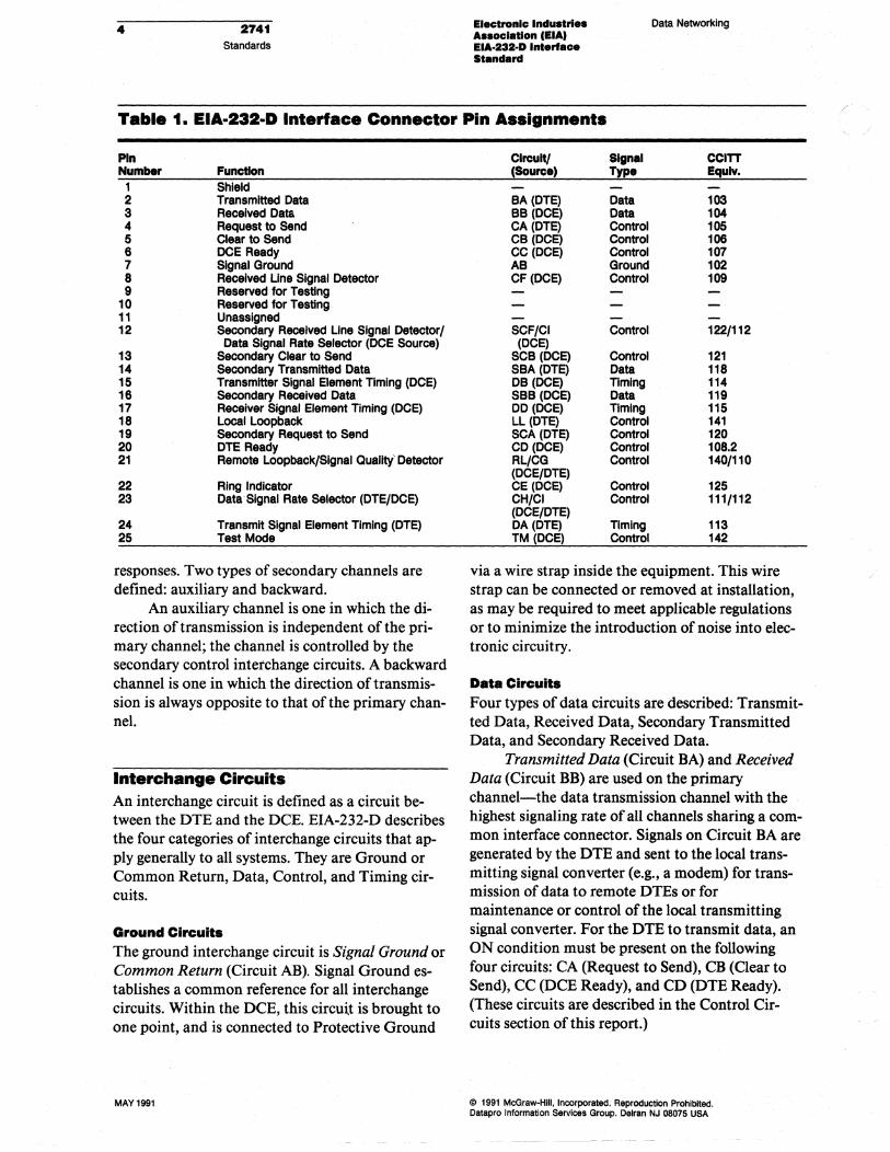
Table 1. EIA-232-D Interface Connector Pin ASSignments
Pin Number
1 2 3 4 5 6 7 8 9
10 11 12
13 14 15 16 17 18 19 20 21
22 23
24 25
Function Shield Transmitted Data Received Data Request to Send Clear to Send DeE Ready Signal Ground Received Line Signal Detector Reserved for Testing Reserved for Testing Unassigned Secondary Received Une Signal Detector/ Data Signal Rate Selector (DCE Source)
Secondary Clear to Send Secondary Transmitted Data Transmitter Signal Element Timing (DCE) Secondary Received Data Receiver Signal Element Timing (DCE) Local Loopback Secondary Request to Send DTE Ready Remote Loopback/Slgnal Quality' Detector
Ring Indicator Data· Signal Rate Selector (DTE/DCE)
Transmit Signal Element Timing (DTE) Test Mode
responses. Two types of secondary channels are defined: auxiliary and backward.
An auxiliary channel is one in which the direction of transmission is independent of the primary channel; the channel is controlled by the secondary control interchange circuits. A backward channel is one in which the direction of transmission is always opposite to that of the primary channel.
Interchange Circuits An interchange circuit is defined as a circuit between the DTE and the DCE. EIA-232-D describes the four categories of interchange circuits that apply generally to all systems. They are Ground or Common Return, Data, Control, and Timing circuits.
Ground Circuits The ground interchange circuit is Signal Ground or Common Return (Circuit AB). Signal Ground establishes a common reference for all interchange circuits. Within the DCE, this circuit is brought to one point, and is connected to Protective Ground
MAY 1991
Circuit! SIgnal CCITT (Source) Type Equlv.
BA (DTE) Data 103 BB (DCE) Data 104 CA (DTE) Control 105 CB (DCE) Control 106 CC (DCE) Control 107 AB Ground 102 CF (DCE) Control 109
SCF/CI Control 122/112 (DCE)
SCB (DCE) Control 121 SBA(DTE) Data 118 DB (DeE) Timing 114 SBB (DCE) Data 119 DO (DCE) Timing 115 LL (DTE) Control 141 SCA (DTE) Control 120 CD (DCE) Control 108.2 RL/CG Control 140/110 (DCE/DTE) CE (DCE) Control 125 CH/CI Control 111/112 (DeE/DTE) DA (DTE) Timing 113 TM (DCE) Control 142
via a wire strap inside the equipment. This wire strap can be connected or removed at installation, as may be required to meet applicable regulations or to minimize the introduction of noise into electronic circuitry.
Data Circuits Four types of data circuits are described: Transmitted Data, Received Data, Secondary Transmitted Data, and Secondary Received Data.
Transmitted Data (Circuit BA) and Received Data (Circuit BB) are used on the primary channel-the data transmission channel with the highest signaling rate of all channels sharing a common interface connector. Signals on Circuit BA are generated by the DTE and sent to the local transmitting signal converter (e.g., a modem) for transmission of data to remote DTEs or for maintenance or control of the local transmitting signal converter. For the DTE to transmit data, an ON condition must be present on the following four circuits: CA (Request to Send), CB (Clear to Send), CC (DCE Ready), and CD (DTE Ready). (These circuits are described in the Control Circuits section of this report.)
@ 1991 McGraw-Hili, Incorporated. Reproduction Prohibited. Datapro Information Services Group. Delran NJ 08075 USA
(
Data Networking Electronic Indu.trI .. Auoclatlon (EIA) EIA·232-D Interface Standard
Signals on Circuit BB are generated by the receiving signal converter in response to data signals received from the remote DTE, or in response to maintenance or control data signals from the local DTE. Circuit BB is held in the binary one (Marking) condition when Circuit CF (Received Line Signal Detector) is in the OFF condition.
Secondary Transmitted Data (Circuit SBA) is equivalent to Circuit BA, except it is used to transmit data on the secondary channel. The secondary channel has a lower signaling rate than the primary channel in a system where two channels share a common interface connector.
Secondary Received Data (Circuit SBB) is equivalent to Circuit BB, except it is used to receive data on the secondary channel.
Secondary circuits may be independent of other interchange circuits in terms of direction and speed. The secondary interchange circuits, however, are additional circuits that function in the same manner as their basic counterparts, and follow the same conditions that govern corresponding basic circuits.
When any data circuit is idle, it is held in the Marking condition. Data is transferred in bipolar fashion; a binary "one" (mark) is represented by a voltage more negative than -3 volts, and a binary "zero" (space) is represented by a voltage more positive than + 3 volts.
Control Circuits Control signals are used to enable and disable data transmission and reception, and to indicate the operational status and condition of the DTE and DCE. A control function is considered to be in the ON condition when the voltage is more positive than + 3 volts; it is considered to be in the OFF condition when the voltage is more negative than -3 volts.
Control circuits include Request to Send, Clear to Send, DCE Ready, DTE Ready, Ring Indicator, Received Line Signal Detector, Signal Quality Detector, Data Signal Rate Selector (DTE), Data Signal Rate Selector (DCE), Secondary Request to Send, Secondary Clear to Send, and Secondary Received Line Signal Detector.
• Request to Send (Circuit CA)-conditions the local DCE for data transmission, and controls the direction of transmission on half-duplex channels. On half-duplex channels, Circuit CA maintains the DCE in the transmit mode and
@) 1991 McGraW-Hili, Incorporated. Reproduction Prohibited. Datapro Information Services Group. Dslran NJ 08075 USA
2741 Standards
5
Table 2. EIA·232·D Data Transmission Configuration Interfaces
Interface Type A B C o o E F
G
H
J
K
L
L
M
Z
ConfIguration Transmit only Transmit only· ReceIve only Half duplex Full duplex· Full duplex PrImary channel transmit only· I secondary channel receIve only
PrImary channel racelve onlyl secondary channel transmit only·
PrImary channel transmit onlyl secondary channel receive only
Prfmary channel receIve onlyl secondary channel transmit only
PrImary channel transmit only· I half-dupfex secondary channel
Prfmary channel racelve onlyl half-duplex secondary channel
Half-dupfex prImary channell half-duplex secondary channel
Full-duplex prfmary channel· I full-duplex secondary channel·
Full-duplex prfmary channel, full-duplex secondary channel
Circuit specIfied by supplier
·,ndlca1e8 the Request to Send (RTS) Circuit In a simplex or full~uplex arrangement where RTS might not ordinarily be ex· pected. Can be used to Indicate a nontransmlt mode to the DeE 01 to permit the DeE to ,.,.ave a line signal 01 to send synchronization signals.
inhibits the receive mode; on simplex channels, it maintains the DCE in the transmit mode. An OFF to ON transition on Circuit CA causes the DCE to enter transmit mode and tum Clear to Send ON. An ON to OFF transition causes the DCE to complete the data transmission, enter the receive or nontransmit mode, and tum Clear to Send OFF.
• Clear to Send (Circuit CB)-indicates to the DTE that data can be transmitted (Circuit CB ON) or cannot be transmitted (Circuit CB OFF). The ON condition on Circuit CB is delayed until the remote DCE is initialized. When Circuit CA is not implemented, Circuit CB must be ON continuously.
• DCE Ready (Circuit CC)-indicates the status of the local DCE. ON indicates that the DCE is connected to the communications channel (in switched services, "Off Hook"), and is not in test, talk (alternative voice/data), or dial mode. The ON condition of this circuit should not be interpreted as either the status of any remote station equipment or an indication that a communications channel has been established to a remote data station. ON indicates completed
MAY 1991

& 2741 Standards
timing functions, if any, required for call establishment (switched service). ON indicates completed transmission of a discreet answer tone, the duration of which is controlled by the local DCE. OFF indicates that the local DCE is not ready to operate, that a fault condition has been detected, or that a disconnect indication has been detected. When the OFF condition occurs during transmission, the connection has been lost.
• DTE Ready (Circuit CD)-controls the switching of the DCE to the communications channel. The ON condition prepares the DCE to connect and maintain connection to the communications channel. With automatic answering equipment, connection to the communications channel occurs when both the DTE Ready and the Ring Indicator circuit are in the ON condition. The OFF condition of Circuit CD causes the DCE to be removed from the communications channel upon completion of any in process transmission. The OFF condition does not disable the Ring Indicator signal. In switched systems, Circuit CD cannot be turned ON until Circuit CC (DCE Ready) is turned OFF by the DCE.
• Ring Indicator (Circuit CE)-indicates that a ring (call) signal is being received on the communications channel through the switched network. Circuit CE is held in the ON condition during ringing and the OFF condition between rings or when ringing is not present.
• Received Line Signal Detector (Circuit CF)presents an ON condition to indicate that data signals are being received, and that they are acceptable for demodulation. An OFF condition indicates that no signal is being received or that the signal is not acceptable for demodulation. The OFF condition causes the Received Data (Circuit BB) to be held in the Marking condition.
• Signal Quality Detector (Circuit CG)indicates whether there is a high probability of error in received data. The ON condition is maintained, unless a high probability of error has occurred. Probable error is indicated by the OFF condition. This condition can be used to effect retransmission.
• Data Signal Rate Selector (DTE Source), Data Signal Rate Selector (DCE Source), (Circuits
MAY 1991
Electronic Induatrl .. AssoclaUon lElA) EIA·232-D Interface Standard
Data Networking
CH and CI, respectively)-selects between two signaling rates when either the DCE or DTE accommodates dual rates. The ON condition selects the higher rate or range of rates. Circuit CH indicates that the DTE provides the selection signal. Circuit CI indicates that the DCE provides the selection signal. Selection is between two asynchronous rates or between two synchronous rates.
• Secondary Request to Send (Circuit SCA)functions the same as Circuit CA, except that it requests the establishment of the secondary channel.
• Secondary Clear to Send (Circuit SCB)functions the same as Circuit CB, except that it indicates the availability of the secondary channel.
• Secondary Received Line Signal Detector (Circuit SCF)-functions the same as Circuit CF, except that it indicates the proper reception of the secondary channel line signal.
Timing Circuits Three circuits are used to provide timing: Transmitter Signal Element Timing (DTE Source), Transmitter Signal Element Timing (DCE Source), and Receiver Signal Element Tiining (DCE Source).
• Transmitter Signal Element Timing (DTE Source) (Circuit DA)-provides signal element timing information to the transmitting signal converter, the DCE. The ON-OFF transition indicates the occurrence of the center of the data element. The DTE normally provides timing information on this circuit when the DTE is powered ON. If Circuit CA (Request to Send) is OFF, timing information on Circuit DA may be withheld by the DTE for short periods.
• Transmitter Signal Element Timing (DCE Source) (Circuit DB)-provides signal element timing to the DTE. A data signal on Circuit BA (Transmitted Data) is provided from the DTE in which the transition between signal elements occurs at the time of the ON-OFF transition in Circuit DB. If Circuit CC (Data Set Ready) is OFF, it is permissible for the DCE to withhold timing information for short periods. The performance of maintenance tests within the DCE, for example, may require the withholding of timing information.
@ 1991 McGraW-Hili. Incorporated. Reproduction Prohibited. Datapro Information Services Group. Delran NJ 08075 USA

Data Networking Electronic Industries Association lElA) EIA-232-D Interface Standard
2741 Standards
7
l Table 3. Required Interchange Circuit. for Standard Interface Type.
(
AB BA BB CA CB CC CD CE CF CG CH/CI
DAIDB
DO
SBA SBB SCA SCB SCF
LL RL TM Legend:
Interchange CIrcuits A Signal Ground Transmitted Data Received Data Request to Send Clear to Send • DCE Ready DTE Ready t Ring Indicator t Received Line Signal Detector Signal Quality Detector Data Signaling Rate Selector (DTE/DCE)
transmitter Signal Element § Timing (DCE/DTE)
Receiver Signal Element Timing (DCE)
Secondary Transmitted Data Secondary Received Data Secondary Request to Send Secondary Clear to Send Secondary Received Line Signal Detector
Local Loopback Remote Loopback Test Mode (2)
B
t t
§
(2)
C
t t
§
(2)
D
•
t t
§
§
(2) (2) (2)
E
• t t
§
§
(2) (2) (2)
F
•
t t
§
•
(2)
Interlace Type
G H I
•
•
t t t t t t
§
§ §
•
•
(2) (2) (2)
J
•
t t
§
(2)
K
t t
§
§
(2)
L
•
t t
§
§
(2) (2) (2)
M
•
t t
§
§
(2) (2) (2)
z
o o o o o o o o o o
o o
o o o o o
o o o
-BasIc Interchange clrcuit-all systems. t-Addltlonallnterchange circuits required for switched service. §-Addltlonallnterchange circuits required for synchronous service. O-To be specified by the supplier. 0-optlonal.
• Receiver Signal Element Timing (DeE Source) (Circuit DD)-provides timing to the data terminal from the data set. The ON-OFF transition indicates the center of the received data elements.
Standard Interfaces for Selected Configurations EIA-232-D describes a selected set of data transmission configurations or interfaces. A provision is made for the addition of custom configurations. Determining factors in the selection of an interface type are whether the DTE transmits, receives, or does both; whether the mode of operation is half or full duplex; and whether a secondary channel is used. The interface designations do not relate to which terminal originates or answers the call, but rather to the data transmitted.
@ 1991 McGraw-Hili, Incorporated. Reproduction Prohibited. Datepro Information Services Group. Delran NJ 08075 USA
EIA-232-D defines selected interface types by letter designation. These types are described in Table 2, where the direction of data transfer pertaining to the interface is stated (function), and the use of Request to Send and Received Line Signal Detector interchange circuits is stipulated (comment). This list indicates that interfaces A and B, which are one-way only transmissions, differ only in terms ofthe use ofRTS. Interface D is normally employed with half-duplex operation using RTS, and intepface E is normally employed with fullduplex operation, without using RTS. When interface D is used in full-duplex operation, however, RTS is used with special significance.
Interfaces E, P, G, and H define two-way transmission where both the primary and secondary directions are one-way only.
Interfaces J, K, L, and M define less restrictive primary and secondary arrangements.
Interface Z simply allows a special arrangement to be established.
The complete relationship of interchange circuits to standard interface types is depicted in Table 3 .•
MAY 1991