
ANSI C80-6
13
ANSI C80.6-1994 Intermediate Metal Conduit- Zinc Coated National Electrical Manufacturers Association 1300 N. 17th Street Suite 1847 Rosslyn, Virginia 22209 ;an National Standard vith permission of the American Ir resale. No part of this publication n, electronic retrieval system or lission ofthe American National :treet, New York, New York 10036. 'L American NauOnal Standaj (703) 841-3300 COPYRIGHT American National Standards Institute Licensed by Information Handling Services COPYRIGHT American National Standards Institute Licensed by Information Handling Services
-
Upload
carlosferia -
Category
Documents
-
view
780 -
download
29
Transcript of ANSI C80-6
ANSI C80.6-1994
Intermediate Metal Conduit-
Zinc Coated
Nat ional E lectr ica l Manufacturers Associat ion
1300 N . 17th Street Sui te 1847
R o s s l y n , Virginia 2 2 2 0 9 ;an National Standard vith permission of the American Ir resale. No part of this publication n, electronic retrieval system or lission ofthe American National :treet, New York, New York 10036.
'L American NauOnal Standaj
(703) 841-3300
COPYRIGHT American National Standards InstituteLicensed by Information Handling ServicesCOPYRIGHT American National Standards InstituteLicensed by Information Handling Services
A N S I C B 0 . b 9 4 0724150 0535439 737 m
ANSI@ C80.6-1994
American National Standard
Intermediate Metal Conduit- Zinc Coated (IMC)
Secretariat National Electrical Manufacturers Association
Approved May 1994 American National Standards Institution, Inc.
Abstract This standard has been developed to specify dimensions and weights for zinc-coated steel intermediate metal conduit, elbows, couplings and nipples for use as an electrical raceway. Trade size designators (metric size designators) range from 1/2 (16 IMC) to 4 (103 IMC). Basic data for threads are included as well as requisite tests for mechanical properties of the conduit.
COPYRIGHT American National Standards InstituteLicensed by Information Handling ServicesCOPYRIGHT American National Standards InstituteLicensed by Information Handling Services
ANSI CB0.b 9 4 07241150 0 5 3 5 4 4 0 459
America National
n Approval of an American National Standard requires verification by ANSI that the requirements for due process, consensus, and other criteria for approval have been met by the standards developer.
Standard Consensus is established when, in the judgment of the ANSI ba rd of Standards Review, substantial agreement has been reached by directly and materially affected interests. Substantial agreement means much more than a simple maprity, but not necessarily unanimity. Consensus requires that all views and objections be considered, and that a concerted effort be made toward their resolution.
The use of American National Standards is completely voluntary; their existence does not in any respect preclude anyone, whether he has approved the standards or not, from manufacturing, marketing, purchasing, or using products, processes, or procedures not conforming to the standards.
The American National Standards Institute does not develop standards and will in no circumstances give an interpretation of any American National Standard. Moreover, no person shall have the right or authority to issue an interpretation of an American National Standard in the name of the American National Standards Institute. Requests for interpretations should be addressed to the secretariat or sponsor whose name appears on the title page of this standard.
CAUTION NOTICE: This American National Standard may be revised or withdrawn at any time. The procedures of the American National Standards Institute require that action be taken to reaffirm, revise, or withdraw this standard no later than fwe years from the date of approval. Purchasers of American National Standards may receive current information on all standards by calling or writing the American National Standards Institute.
Published by
National Electrical Manufacturers Association 1300 N. 17th Street, Rosslyn, Virginia 22209
Copyright O 1995 by American National Standards Institute, Inc. All rights reserved.
Printed in the United States of America AlM11W6
COPYRIGHT American National Standards InstituteLicensed by Information Handling ServicesCOPYRIGHT American National Standards InstituteLicensed by Information Handling Services
ANSI C8O.b 9 4 0 7 2 4 3 5 0 0535443 395
ANSI C80.6-1994
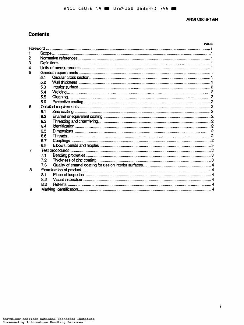
Contents
PAGE Foreword ......................................................................................................................................................... i
2 Normative references ........................................................................................................................... 1 3 Definrtlons 1 4 Units of measurements ......................................................................................................................... 1 5 General requirements ........................................................................................................................... 1
5.1 Circular cross section ................................................................................................................. 1 5.2 Wall thickness ............................................................................................................................ 1 5.3 Interior surface ........................................................................................................................... 2 5.4 Welding ...................................................................................................................................... 2 5.5 Cleaning ..................................................................................................................................... 2 5.6 Protective coating ...................................................................................................................... 2
6 Detailed requirements ........................................................................................................................... 2 6.1 Zinc coating ................................................................................................................................ 2 6.2 Enamel or equivalent coating ..................................................................................................... 2 6.3 Threading and chamfering ......................................................................................................... 2 6.4 Identification ............................................................................................................................... 2 6.5 Dimensions ................................................................................................................................ 2 6.6 Threads ...................................................................................................................................... 2 6.7 Couplings ................................................................................................................................... 2 6.8 Elbows, bends and nipples ........................................................................................................ 3
7 Test procedures .................................................................................................................................... 3 7.1 Bending properties ..................................................................................................................... 3
7.3 QuaMy of enamel coating for use on interior surfaces ............................................................... 4 8 Examination of product ......................................................................................................................... 4
8.1 Place of inspection ..................................................................................................................... 4 8.2 V i a l inspection ........................................................................................................................ 4 8.3 Retests ....................................................................................................................................... 4
9 Marking Identifikation ............................................................................................................................ 4
1 scope .................................................................................................................................................... 1
.. .............................................................................................................................................
7.2 Thickness of zinc coating ........................................................................................................... 3
1
COPYRIGHT American National Standards InstituteLicensed by Information Handling ServicesCOPYRIGHT American National Standards InstituteLicensed by Information Handling Services
ANSI (380.6-1994
This standard was developed by the Accredited Standards Committee on Raceways for Electrical Wiring Systems, C80. The obpctive of the committee is to produce a comprehensive specification that would establish uniform dimensions and standard construction requirements for rigid metal conduit, electrical metallic tubing, intermediate metal cow¡ and rigid aluminum conduit raceway products and their associated components.
The standard was originally approved in 1986.
Suggestions for improvement of this standard will be welcome. They should be sent to the National Electrical Manufacturers Association, 1300 N. 17th Street, Rosslyn, Virginia 22209.
This standard was processed and approved for submittal to ANSI by the Accredited standards Committee on Raceways for Electrical Wiring Systems, C80. Committee approval of the standard does not necessarily imply that all committee members voted for its approval. At the time it approved this standard, the C80 Committee had the fdlOWing members:
J. A Gmber, Chairman J. A. Gauthier, Secretary
Organizathn Represented
Aluminum Association American Iron and steel Institute American Ppe F~ings Association International AssocWin of Electrical Inspectors International Brathemood of Electrical Workers
Nationai Electrical Contractors Association National Electrical Manufacturers Association
Name of Representative
P. Pollak M. Pahoda R. T. Bryson W. tirly K. R. Edwards J. Widener C. H. Williams A. W. Ballard C. W. Beile D. Gearing J. A. Gruber J. H. Kuczka T. McNeive S. Schauffele R. Hggenbottom (Alt.) P. Horton (Alt.) R. Jazowski (Alt.) F. W. McGeehan G. Rusinski R. LaRocca (Alt.)
COPYRIGHT American National Standards InstituteLicensed by Information Handling ServicesCOPYRIGHT American National Standards InstituteLicensed by Information Handling Services
A N S I C B O - b 7 4 0724350 0535443 L b B
AMERICAN wnowL STANDARD ANSI C80.6-1994
American National Standard for Intermediate Metal Conduit (1MC)- Zinc Coated
1.1 This standard covers the requirements for intermediate metal conduit for use as a raceway for the wires or cables of an electrical system. The conduit is furnished in nominal 104 (3.05m) lengths, threaded on each end with one coupling attached. It is protected on the exterior surface with a metallic zinc coating and on the interior surface with a zinc, enamel, or other equivalent corrosion-resistant coating.
1.2 This standard also covers conduit couplings, elbows, bends, and nipples and lengths other than 10 ft (3.05 m).
2 Normative reference
The following standard contains provisions which, through reference in this text, constitute provisions of this American National Standard. At the time of publication, the edition indicated was valid. All standards are subject to revision, and parties to agreements based on ths American National Standard are encouraged to investigate the possibility of applying the most recent edition of the standard indi ied below.
ANSVASME B1 -20.1 -1983 (R1 992), Pipe Threau3, General Purpose (inch)
3 Definitions
3.1 Threaded coupling A threaded coupling for intermediate metal conduit is an internally threaded s t e e l cylinder for connecting two sections of intermediate metal conduit.
3.2 Elbow and bend An elbow or bend is a curved section of intermediate metal conduit threaded on each end.
3.3 Nipple A nipple is a straight section of intermediate metal conduit not more than 2 ft (0.61 m) long and threaded on each end.
4 Units of measurement
The values states in inch-pound units are to be regarded as the standard. The metric equivalents may be approximate.
5 General requirements
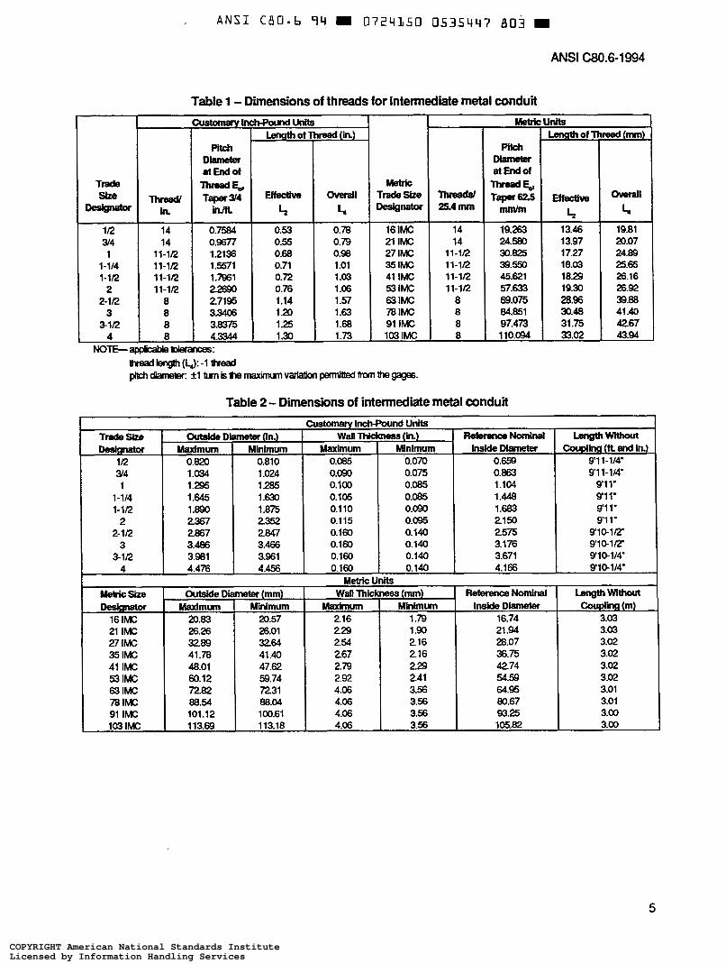
5.1 Circolar cross section intermediate metal conduit shall have a circular cross section sufficiently accurate to permit the cutting of threads in accordance with table 1.
5.2 Wall thickness The wall thickness shall be in accordance with table 2.
1
COPYRIGHT American National Standards InstituteLicensed by Information Handling ServicesCOPYRIGHT American National Standards InstituteLicensed by Information Handling Services
A N S I C B O - b 9 4 W 0724350 0535444 O T 4
ANSI C80.6-1994
5.3 Interior surface The interior surface shall be free from injuriws defects.
5.4 Welding The welding of all seams shall be continuous and done in a workmanlike manner.
5.5 Cleaning The conduit shall be adequately cleaned before the application of the protective coating. The cleaning process shall leave the exterior and interior surfaces of the conduit in such a condition that the protective coating shall be firmly adherent and smooth.
5.6 Protective coating
5.6.1 The exterior surface shall be thoroughly and evenly coated with metallic zinc applied directly to the surface of the steel so that metal-temetal contact and galvanic protedion against corrOsion are provided.
5.6.2 The interior surface shall be protected by a zinc, enamel, or other suitable corrosion-resistant coating.
6 D e t a i l e d requirements
6.1 Zinc coating The zinc content of the coating on the outside surface shall be equivalent to a minimum thickness of 0.0008 in. (0.02 mm.)
6.2 Enamel or equivalent coating Enamel or other equivalent protective coating shall have a smooth continuous surface. An occasional variation due to uneven flow of coating shall be acceptable. The coating shall not soften at a temperature of 120°F (49°C) and shall be sufficiently elastic to meet the test described in 7.3.
6.3 Threading and chamfering Each length of conduit, nipple, elbow, and bend shall be threaded on both ends, and each end shall be chamfered or atherwise treated to remove burrs and sharp edges.
Threads shall comply with the requirements of 6.6. I f threads are cut after the zinc coating has been applied, the threads shall be treated with a protective coating to prevent conosion before installation. This treatment shall not impair electrical continuity through couplings or fittings after installation.
6.4 kientification Each length of conduit, nipple, elbow and bend shall be -dentif& with the manufacturer's name or trademark and the letters IMC at least 1/8 in. (3 mm) high, except that close threaded nipples need not be so identified.
6.5 Dimensions The dimensions of intermediate metal conduit shall be in accordance with table 2.
6.6 Threads The number of threads per inch (25.4 mm), and the length of the threaded portion at each end of each length of conduit, nipple, elbow and bend shall be as indicated in table 1, and shall conform to American National standard Pipe Threads (inch) ANSVASME B1.20.1-1983 (R-1992). The perfect thread shall be tapered for its entire length, and the taper shall be 3 4 ¡Mt (62.5 mnVm).
6.7 Couplings Couplings shall comply with the following requirements:
2
COPYRIGHT American National Standards InstituteLicensed by Information Handling ServicesCOPYRIGHT American National Standards InstituteLicensed by Information Handling Services
A N S I C B O - h '74 0724350 0535445 T30
ANSI C80.6-1994
6.7.1 The exterior surface of couplings shall be protected by means of a zinc coating, which shall comply with the requirements of 6.1. The interior surface shall be treated to inhibit com>sion from taking p h prior to
6.7.2 Couplings shall be so made that all threads on the conduit will be covered when the coupling is pulled tight on standard conduit threads.
6.7.3 Both ends of the coupling shall be chamfered to prevent damage to the starting thread.
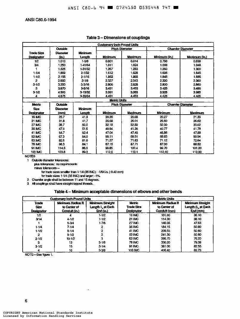
6.7.4 The outside diameter, length, pitch diameter, and chamfer diameter of couplings shall be as indicated in table 3.
6.75 Couplings shall be straight tapped.
6.7.6 Each length of finished conduit shall have one coupling attached.
6.8 Elbows, bends and nipples conduit elbows, bends and nipples shall be made of a similar grade of steel to that employed in straight lengths of intermed'hte metal conduit, and shall be treated, coated, threaded, and rnatked for identaication according to the a p p l i i e requirements for intermediate metal conduit (zinc coated).
No bend other than at the end curve of a gooseneck shall be sharper than 90 degrees. The sharpest acceptable end curve is 135 degrees. No bend shall be shallower than 15 degrees. The length Ls of the straight portions at the ends of a bend and the radius R shall not be less than indicated in table 4 for each size of conduit. Figure 1 illustrates the dimensions for conduit bends.
7 Test procedures
7.1 Bending properties
7.1.1 Ductility of steel conduits shall be capable of being bent cold into a quarter of a circle around a mandrel, the radius of which is shown in table 4, withcut developing cracks at any portion and without opening the weld.
7.1.2 Ductility of zinc coating The protective coatings used on the exterior and interior surfaces of rigid steel conduit shall be sufficiently elastic to prevent their cracking or flaking off when a finished sample of trade size designator 112 (16 IMC) or the smallest trade size manufactured is tested. Test shall be performed within 1 year after the time of manufacture, by bending 112 (16 IMC) into a halfcircle around a mandrel, the radius of which is shown in table 4 or by bending other trade size designators into a quartercircle around a mandrel, the radius of which is shown in table 4.
Compliance of trade size designators 1/2 (16 IMC) and 3/4 (21 IMC) shall be determined by bending the conduit with a form as shown in fgure 1. Compliance of trade sue designators larger than 3/4 (21 IMC) shall be determined by bending the conduit with any suitable bending equipment.
7.2 Thickness of zinc coating One of the following test methods shall be employed for measuring the thickness or extent of the external zinc coating on conduit:
- Magnetictest - Preece test (material that will withstand four 1-minute immersions shall be considered as meeting the
requirements of 6.1.
3
COPYRIGHT American National Standards InstituteLicensed by Information Handling ServicesCOPYRIGHT American National Standards InstituteLicensed by Information Handling Services
ANSI C80.6-1994
7.3 Q u a l ¡ of enamel coating for use on interior surfaces Test pieces of uncoated sheet steel, 3 in. (76.2 mm) wide, 5 in. (127.00 mm) kmg, and 0.010 in. (0.25 mm) thid<, shall be cleaned with a suitable solvent to remove all grease and foreign material. Each piece shall be dipped into the enamel that is used for coating the conduit and the coated test pieces shall be allowed to airdry for 30 minutes before being placed in the baking oven. Each piece shall be suspended by means of short wires in the baking oven and the samples shall be baked for a period of 5 hours at the m l baking temperature for the enamel in question, except that if the normal baking temperature is less than 275°F (135°C) or if the enamel is regularly airdried, the oven temperature shall be maintained at 275°F to 302°F (135°C to 1 W C ) .
At the end of the 5hour period, the test samples shall be removed from the oven and allowed to air-cool to room temperature. Each test piece shall be gripped in a vise . a n d then bent from the opposite side back and forth ten times through an angle of 180 degrees, the radius of the bend being 1/16 in. (1.53 mm). When so tested, the enamel coating on the sample shall not crack or flake.
8 Inspection
8.1 Place of inspection All tests and inspections shall be made at the place of manufacture prior to shipment, unless otherwise specified, and shall be so conducted as not to interfere with normal manufacturing processes.
8.2 Visual inspection Each length of conduit shall be examined visually, both on the exterior and interior surfaces to determine if the produd is free from slivers, burrs, scale, or other similar injurious defects, and if coverage of the coating is complete-
8.3 Retests If any sample tested as prescribed in this specification should fail, two additional samples shall be tested, both of which shall comply with the requirements of this specification.
9 Marking Identification
Each length of conduit, nipple, elbow and bend shall be identified with the manufacturer's name or trademark and the letters IMC at least 143 in. (3 mm) high, except that close threaded nipples need not be so identified.
4
COPYRIGHT American National Standards InstituteLicensed by Information Handling ServicesCOPYRIGHT American National Standards InstituteLicensed by Information Handling Services
A N S I C B O - b 9 4 0 7 2 4 3 5 0 0535447 803
Trade she
W- 1R 34 1
1-114 1-1R
2 2-1R
3 81R
A
Threadl h 14 14
11" 11-1R 11-1R 11-1R
8 8 8 8
ANSI C80.6-1994
Table 1 - Dimensions of threads for intermediate metal conduit Womw lnctFpound UnHs
Length of Thread (in.) Pitch
Diamder SItEndof
E 2 -1 Effecthre innt I* L,
0.7584
1.73 1.30 4.3344 1 .a 125 3.8375 1.63 1 .20 3.3406 1.57 1.14 27195 1 .o6 0.76 22690 1 .o3 0.72 1 .ml 1 .o1 0.71 1 .W1 0.98 0.68 1.2136 0.79 0.55 0.9677 0.78 0.53
r Metric UnHs
I I LerrsthofT Pitch
Diameter at End of
Metric -E, Trade- Effeahre Tapera Weadd DeSig- mmhn L,
16 IMC
33.02 110.094 8 103 IMC 31 .75 97.473 8 91 I M C 30.48 84.851 a 78 IMC 285 69.075 8 63 I M C 19.30 57.633 Il-li2 53 IMC 18.29 45.621 Il-IR 41 IMC 18.03 39.550 11-1R 35 IMC 17.27 30.825 lt-lR 27 IMC 13.97 24.580 14 21 IMC 13.46 19.263 14
threadlength(U:-l thread piWl~:*1bmisIhenla%imumv"rromthegages.
Table 2 - Dimensions of intermediate metal conduit
!e&!!k
overail
L. 19.81 20.07 24.89 25.65 26.16 26.92 39.88 41.40 4267 43.94
Tradesbe Outside Diameter (In.) Wall Thkkness (in.) ReferenœNominal Desmator Maximum Minimum Maximum Minimum InMeDlameter
IR 0.m 0.810 0.085 0.070 0.659 34 1 .a34 1 .o24 0.090 0.075 0.863 1 1.295 1.285 0.100 0.085 1.104
1-114 1 .W 1 .ex 0.105 0.085 1.448 1-112 1.890 1.875 0.110 0.090 1 .€.W
2 2367 2352 0.115 0.095 2150 2-1R 2867 2847 0.160 0.140 2575
3 3.406 3.466 0.160 0.140 3.176 31R 3.981 3.961 0.160 0.140 3.671
4 4.476 4.456 0.160 0.140 4.166
Couphg (m) 16 IMC I 20.83 1 20.57 I 2.16 I 1.79 I 16.74 1 3.03 21 IMC 27 I M C 35 IMC 41 IMC 53 IMC 63 IMC 78 IMC 91 IMC 103 IMC
26.26 3289 41.78 48.01 60.12 7282 88.54 101.12 113.69
47.62
88.04 100.61 113.18
229 2.54 2.67 279 292 4.06 4.06 4.06 4.06
1 .W
105.82 3.56 93.25 3.56 80.67 3.56 64.95 3.56 54.59 2.41 4274 229 36.75 216 28.07 216 21 .M 3.03
3.02 3.02 3.02 3.02 3.01 3.01 3.00 3.00
5
COPYRIGHT American National Standards InstituteLicensed by Information Handling ServicesCOPYRIGHT American National Standards InstituteLicensed by Information Handling Services
A N S I C B O - b 94 = 0724150 0535448 7 4 T
ANSI C80.6-1994
Table 3 - Dimensions of couplings
Metric Size
Deagnator 16 I M C 21 IMC 27 I M C 35 I M C 41 IMC 53 I M C 63 IMC 78 IMC 91 I M C 103 I M C
Tradesbe DedQnatof
IR W4 1
1-114 1-1R
2 2-1R
3 31R
outside Diameter Minlmum
(in.) I i e n s t h 1 .o10 1-5/8 1 250 1 525 1.889 2155 2650 3.250 3.870 4.500 4.875
1-41164 1-31/32 2-1/32 2-1/16 2-118 m l 6 35/16 3-13/32 3-3364
outside Diameter Minimum
(mm) 25.7 41.3 31.8 41.7 38.7 50.0 47.5 51.6 54.7 524 67.3 54.0 82.6 81 .O 98.3 84.1 114.3 86.5 123.8 89.3
cwtomary I n c h pitch I
Minlmum 0.801 1.011 1.267 1.612 1.852 2327 2806 3.431 3.931 4.431
Metricl Pi¡& I
Minimum 20.35 25.68 32.18 40.94 47.04 59.1 1 71.27 87.15 99.85 112.6
wnd Units uneler
Maximum 0.814 1 .o24 1.283 1.628 1.868 2343 2828 3.453 3.953 4.453
Its meter
Maximum 20.68 26.01 3259 41.35 47.45 59.51 71.83 87.71 1 OO.4 113.1
chamiel
Minimum (h) 0.798 1 .o08 1.260 1 .€us 1 .a45 2320 2800 3.425 3.925 4.425
chamfer
Minimum 20.27 25.60 32.00 40.77 46.86 58.93 71.12 87.00 99.70 11240
Maximum (in.) 0.838 1 .o48 1.300 1.645 1.885 2360 2860 3.485 3.985 4.485
hmetef
Maximum 21.29 26.62 33.02 41.78 47.88 59.94 72.64 88.52 101.20 1 13.90
Table 4 - Minimum acceptable dimensions of elbows and other bends
Metricunits
tocenter of -(Lat- Minimum Radius R M i n i m u m StreigM
Conduit (mm) End (mm) 101.60
38.10 114.30 38.10
85.73 406.40 8255 381 .o0 79.38 330.20 76.20 266.70 50.80 241.30 50.80 209.55 50.80 184.15 47.63 146.05
6
COPYRIGHT American National Standards InstituteLicensed by Information Handling ServicesCOPYRIGHT American National Standards InstituteLicensed by Information Handling Services
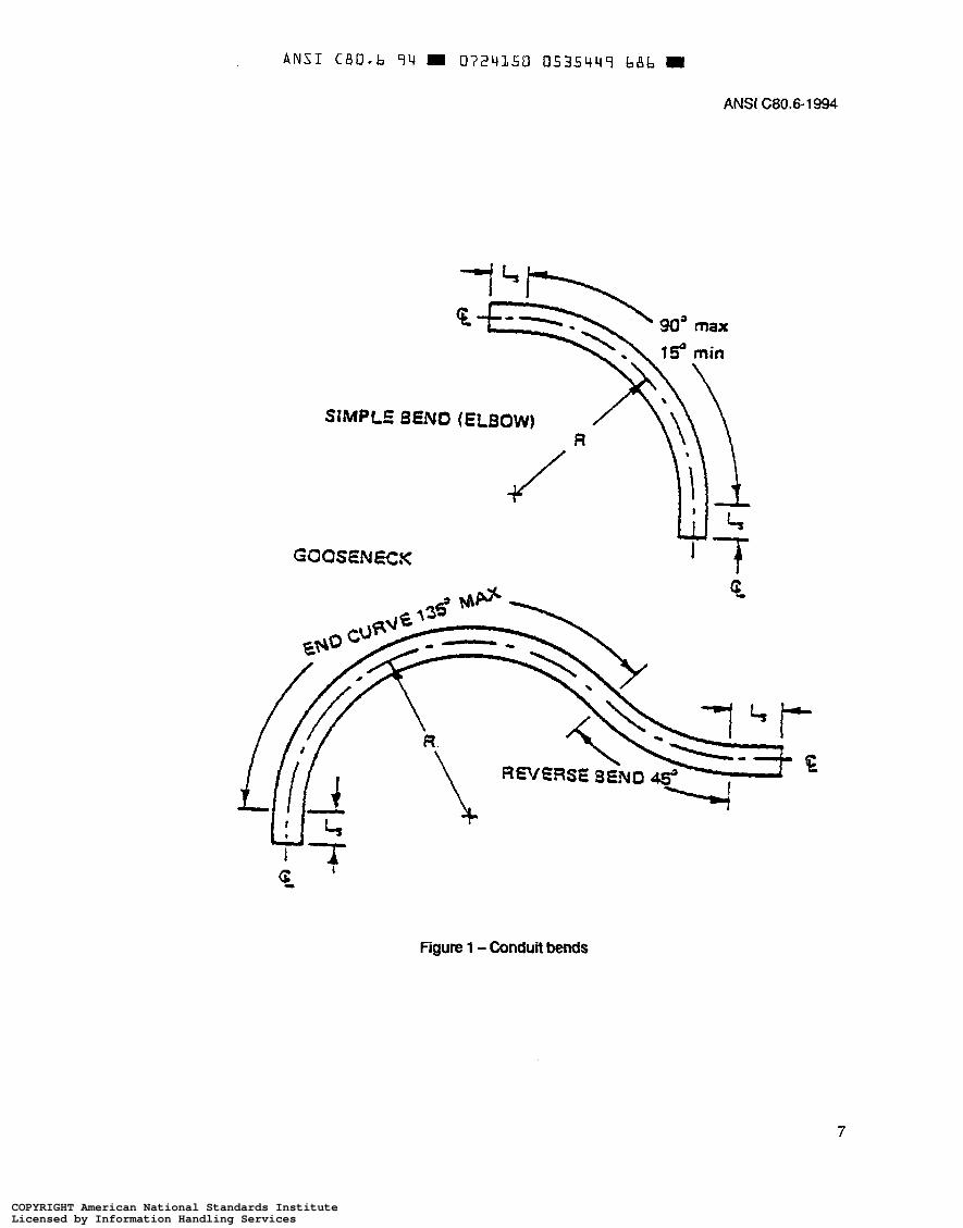
Figure 1 - Conduit bends
7
COPYRIGHT American National Standards InstituteLicensed by Information Handling ServicesCOPYRIGHT American National Standards InstituteLicensed by Information Handling Services
ANSI C B O - b 9 4 0724350 0535450 3 T B
ANSI C80.6-1994
8
COPYRIGHT American National Standards InstituteLicensed by Information Handling ServicesCOPYRIGHT American National Standards InstituteLicensed by Information Handling Services


![;$H16108;7,6$D0,:08/$]$C80 1 1 0$](https://static.fdocuments.us/doc/165x107/616efb564e150256b87eda07/h1610876d008c80-1-1-0.jpg)


