AnObject-OrientedSystemsEngineeringPointofViewtoDevelop ...
17
Research Article An Object-Oriented Systems Engineering Point of View to Develop Controllers of Quadrotor Unmanned Aerial Vehicles Ngo Van Hien , 1 Van-Thuan Truong , 1 and Ngoc-Tam Bui 2,3 1 School of Transportation Engineering, Hanoi University of Science and Technology, Hanoi 10000, Vietnam 2 School of Mechanical Engineering, Hanoi University of Science and Technology, Hanoi 10000, Vietnam 3 College of Systems Engineering and Science, Shibaura Institute of Technology, Tokyo 135-8548, Japan Correspondence should be addressed to Ngo Van Hien; [email protected], Van-Thuan Truong; [email protected], and Ngoc-Tam Bui; [email protected] Received 30 March 2020; Revised 15 June 2020; Accepted 7 July 2020; Published 5 August 2020 Academic Editor: Paolo Castaldi Copyright © 2020 Ngo Van Hien et al. This is an open access article distributed under the Creative Commons Attribution License, which permits unrestricted use, distribution, and reproduction in any medium, provided the original work is properly cited. The aerospace industry needs to be provided with system solutions to technologically challenging and mission-critical problems. Based on the industrial control point of view, development engineers must take costs and existing standards into account in order to effectively design, implement, and deploy control systems with reasonable costs. The customization and reusability are important factors associated with the production of new applications in order to reduce their costs, resources, and development time. In this work, the Model-Driven Architecture (MDA)/Model-Based Systems Engineering (MBSE) approach combined with the real-time Unified Modeling Language (UML)/Systems Modeling Language (SysML), Unscented Kalman Filter (UKF) algorithm, and hybrid automata is specialized to obtain a hybrid control model in order to conveniently deploy controllers of Quadrotor Unmanned Aerial Vehicles (Q-UAVs). This hybrid control model also provides a real-time capsule pattern, which allows the designed elements to be customizable and reusable in new applications of various multirotor UAVs of the Vertical Take-Off and Landing (VTOL) type. The Q-UAV dynamics and control architecture are combined with the MDA/MBSE specialization as follows: the Computation Independent Model (CIM) is defined by specifying the use-case model together with the UKF algorithm and hybrid automata to intensively gather the control requirements. The Platform Independent Model (PIM) is then designed by specializing the real-time UML/SysML’s features to obtain the main control capsules, ports, and protocols, together with their dynamic evolution. The detailed PIM is subsequently transformed into the PSM by open-source platforms to rapidly implement and deploy the Q-UAV controller. The paper ends with trial flights and deployment results that show good feasibility to be used for a trajectory-tracking controller of a low-cost Q-UAV. In this case study, the Q-UAV controller is implemented with the simulation model in the OpenModelica tool. The obtained simulation results then allow the main control elements and their properties to be defined, as well as building the implementation libraries in the Arduino environment based on C++ language to quickly perform the realization model in the ATMEGA32-U2 and STM32 Cortex-M4 microcontrollers. 1. Introduction Unmanned Aerial Vehicles (UAVs) have been used in many military applications for a long time. Currently, UAVs, especially quadrotor UAVs (Q-UAVs), are also being developed rapidly in civilian applications to enhance economic effectiveness, e.g., online shipping in e-commerce, precision agriculture, environmental monitoring, mapping, and surveillance. The Q-UAV is one of the micro-UAV types of which operating modes are capable of Vertical Take-Off and Landing (VTOL) and hovering and horizon- tal flight, so they can handle turbulence due to, for exam- ple, wind more easily and are easier to design and realize by using a compact airframe [1–3]. Systems engineering is an approach that has been widely accepted in the aerospace and defense industry to provide system solutions to technologically challenging and mission-critical problems. The solutions often include Hindawi International Journal of Aerospace Engineering Volume 2020, Article ID 8862864, 17 pages https://doi.org/10.1155/2020/8862864
Transcript of AnObject-OrientedSystemsEngineeringPointofViewtoDevelop ...

Research ArticleAn Object-Oriented Systems Engineering Point of View to DevelopControllers of Quadrotor Unmanned Aerial Vehicles
Ngo Van Hien ,1 Van-Thuan Truong ,1 and Ngoc-Tam Bui 2,3
1School of Transportation Engineering, Hanoi University of Science and Technology, Hanoi 10000, Vietnam2School of Mechanical Engineering, Hanoi University of Science and Technology, Hanoi 10000, Vietnam3College of Systems Engineering and Science, Shibaura Institute of Technology, Tokyo 135-8548, Japan
Correspondence should be addressed to Ngo Van Hien; [email protected],Van-Thuan Truong; [email protected], and Ngoc-Tam Bui; [email protected]
Received 30 March 2020; Revised 15 June 2020; Accepted 7 July 2020; Published 5 August 2020
Academic Editor: Paolo Castaldi
Copyright © 2020 Ngo Van Hien et al. This is an open access article distributed under the Creative Commons Attribution License,which permits unrestricted use, distribution, and reproduction in any medium, provided the original work is properly cited.
The aerospace industry needs to be provided with system solutions to technologically challenging and mission-critical problems.Based on the industrial control point of view, development engineers must take costs and existing standards into account inorder to effectively design, implement, and deploy control systems with reasonable costs. The customization and reusability areimportant factors associated with the production of new applications in order to reduce their costs, resources, and developmenttime. In this work, the Model-Driven Architecture (MDA)/Model-Based Systems Engineering (MBSE) approach combined withthe real-time Unified Modeling Language (UML)/Systems Modeling Language (SysML), Unscented Kalman Filter (UKF)algorithm, and hybrid automata is specialized to obtain a hybrid control model in order to conveniently deploy controllers ofQuadrotor Unmanned Aerial Vehicles (Q-UAVs). This hybrid control model also provides a real-time capsule pattern, whichallows the designed elements to be customizable and reusable in new applications of various multirotor UAVs of the VerticalTake-Off and Landing (VTOL) type. The Q-UAV dynamics and control architecture are combined with the MDA/MBSEspecialization as follows: the Computation Independent Model (CIM) is defined by specifying the use-case model together withthe UKF algorithm and hybrid automata to intensively gather the control requirements. The Platform Independent Model(PIM) is then designed by specializing the real-time UML/SysML’s features to obtain the main control capsules, ports, andprotocols, together with their dynamic evolution. The detailed PIM is subsequently transformed into the PSM by open-sourceplatforms to rapidly implement and deploy the Q-UAV controller. The paper ends with trial flights and deployment results thatshow good feasibility to be used for a trajectory-tracking controller of a low-cost Q-UAV. In this case study, the Q-UAVcontroller is implemented with the simulation model in the OpenModelica tool. The obtained simulation results then allow themain control elements and their properties to be defined, as well as building the implementation libraries in the Arduinoenvironment based on C++ language to quickly perform the realization model in the ATMEGA32-U2 and STM32 Cortex-M4microcontrollers.
1. Introduction
Unmanned Aerial Vehicles (UAVs) have been used inmany military applications for a long time. Currently,UAVs, especially quadrotor UAVs (Q-UAVs), are alsobeing developed rapidly in civilian applications to enhanceeconomic effectiveness, e.g., online shipping in e-commerce,precision agriculture, environmental monitoring, mapping,and surveillance. The Q-UAV is one of the micro-UAV
types of which operating modes are capable of VerticalTake-Off and Landing (VTOL) and hovering and horizon-tal flight, so they can handle turbulence due to, for exam-ple, wind more easily and are easier to design and realizeby using a compact airframe [1–3].
Systems engineering is an approach that has beenwidely accepted in the aerospace and defense industry toprovide system solutions to technologically challengingand mission-critical problems. The solutions often include
HindawiInternational Journal of Aerospace EngineeringVolume 2020, Article ID 8862864, 17 pageshttps://doi.org/10.1155/2020/8862864

the use of hardware and equipment, software, data, people,and facilities [4]. In addition, the low development costs mustbe taken into account in the construction of applications.Thus, reusability must also be considered in the new develop-ment lifecycle of various applications for UAVs, such as theVTOL. According to the Object Management Group(OMG) [5], Unified Modeling Language (UML) has beenstandardized for analyzing and designing visual systemcomponents in the software industry. In addition, SystemModeling Language (SysML) [6] is a UML profile for systemsengineering that has been also standardized by OMG. SysMLis used for analyzing, designing, verifying, and validating thedevelopment artifacts of industrial systems in variousdomains. Nevertheless, both UML and SysML lack the con-structs for precise modeling of timing and communicationevolutions between the control objects for real-time andembedded systems, e.g., the Q-UAV controller. Furthermore,the OMG has also standardized the Model-Driven Archi-tecture (MDA) [7, 8] whose main idea is to separate thespecifications of system operations from the details of theway that a system uses the capabilities of its platform.On the other hand, Model-Based Systems Engineering(MBSE) has been formalized by INCOSE [9, 10] to sup-port the modeling of system requirements, design, analysis,verification, and validation artifacts in the development lifecycle of complex systems.
In addition, the problem of designing autonomous flightcontrollers for Q-UAVs is equally challenging because thesecontrollers are closely connected with the dynamic models[11–13]. Hence, the Q-UAV controller can be considered tobe a model that combines discrete and continuous behaviorsnamed the Hybrid Dynamic System (HDS), and it can bemodeled by hybrid automata (HA) [14–16].
Following on from the above points, the MDA/MBSE’sfeatures can be specialized by combining them with thereal-time UML [17–20] together with the SysML (i.e., real-time UML/SysML) to depict the analysis and design compo-nents of control systems in detail. This study focuses on thedevelopment of a hybrid control model that integrates theQ-UAV dynamics specialized for the MDA/MBSE togetherwith real-time object paradigms and the HA, which permitsus to conveniently implement the Q-UAV controller. Thismodel also allows the designed control components to beclosely customized and reused for deploying new controlapplications of various UAV types capable of VTOL. In thiswork, the Q-UAV dynamics and control architecture arecombined with the specialization of MDA/MBSE features,composed of the Computation Independent Model (CIM),Platform Independent Model (PIM), and Platform SpecificModel (PSM). The control system permits a Q-UAV to trackthe desired trajectories. In detail, the CIM consists of the use-case model defined closely with an implemented functionblock diagram, the supplemented Unscented Kalman Filter(UKF) algorithm, and HA to accurately meet the controlrequirements for a Q-UAV controller. Based on the definedCIM, the PIM is designed by specifying the real-time UML/-SysML that allows a real-time capsule pattern to be created tomodel the real-time control elements with their timing evolu-tions in detail. The detailed PIM components are then trans-
formed into PSMs by using open-source platforms such asOpenModelica [21] and Arduino [22] in order to rapidlyimplement and deploy the Q-UAV controller. Finally, atrajectory-tracking controller of an application of Q-UAV isdeployed and used to test the ATMEGA U2 and STM32-Cor-tex-M4 microcontrollers, which are linked with the InertialMeasurement Unit (IMU) MPU6000 with a working fre-quency of 100Hz [23] and GPS Ublox Neo 6M with a work-ing frequency of 10Hz [24]. This controller is trialed throughdifferent experimental scenarios and is compared to existingsolutions.
In this study, we followed the method of our authorintroduced in Van Hien et al. [25]. The main contributionsof this paper are summarized as follows:
(1) The MDA/MBSE approach combined with the real-time UML/SysML, UKF algorithm, and hybridautomata is specialized to conveniently analyze,design, implement, and deploy the Q-UAV controller
(2) The main designed control capsules can be custom-ized and reused for various UAV types capable ofVTOL
(3) The open-source platforms are used to rapidly imple-ment and deploy the controller
(4) A trajectory-tracking controller of a low-cost Q-UAVis developed and tested
The rest of this paper is organized as follows: The secondsection introduces the related works that inspired us to buildan MDA/MBSE-oriented development life cycle for Q-UAVcontrollers. The Q-UAV dynamic model and control archi-tecture are introduced in the third section. The fourth sectionpresents the details of MDA/MBSE-based development toconveniently realize and deploy Q-UAV controllers, includ-ing the CIM, PIM, and PSM components. In the fifth section,this specialized model is applied to a case study. Conclusionsand future work are shown in the final section.
2. Related Work
2.1. Structural Approaches for Q-UAV Controllers. In thepresent design of complex systems, many applications usestandard control methods together with soft-computingapproaches to make them more effective for controllers ofsuch systems [26–30]. These have also been applied to theconstruction of Q-UAV controllers; for example, some ofthe main control methods and assessments for Q-UAVapplications are summarized in Table 1.
The assessment results of the above control approachessuggest the use of a combination of PID and backstepping,the so-called Integral Backstepping (IB) technique. This isused to implement the continuous evolution of the Q-UAVcontroller by a functional block diagram in the fourthsection.
In addition, the above traditional control models arebased on structural approaches that focus on database-driven architecture. Hence, the designed control components
2 International Journal of Aerospace Engineering

could be difficult to customize and reuse for realizing newcontrollers of different UAVs of the VTOL type and fordeploying them appropriately into various software andhardware platforms. To achieve this goal, model-drivenapproaches can be specialized to conveniently perform thewhole development lifecycle focused on control systems suchas the Q-UAV controller.
2.2. Model-Driven Approaches and Applications. As previ-ously stated, the MDA has been standardized by OMG forsystem design, development, and implementation. The threemain goals of the MDA are portability, interoperability, andreusability through an architectural separation of concerns.Furthermore, Model-Based Systems Engineering (MBSE) isthe formalized application of modeling that is used tosupport system requirements and for design, analysis, verifi-cation, and validation activities beginning in the conceptualdesign phase and continuing throughout development andlater life cycle phases [9, 10]. MDA is a system developmentparadigm that emphasizes the use of rigorous visual model-ing techniques throughout the system development life cycle(SDLC), and MBSE is a specialization of MDA that appliesMDA principles and best practices to systems engineeringapplications [25, 50]. Following the above model-basedapproaches, Ragavan et al. [51] proposed the Bond Graph-based Unified Meta-Modeling Framework (BG-UMF) tolead the complexity in model transformation, analysis,validation, verification, and automatic code generation,which are focused on the conceptual design and developmentof executable models for large engineering systems. Herreraet al. [52] introduced the complex UML/MARTE (Modelingand Analysis of Real-Time and Embedded Systems) method-ology to design embedded systems, which brought out a newintegration of Model-Driven Engineering (MDE), electronicsystems, and space exploration technologies. This platformcould capture the set of possible design solutions by usingthe UML and the standard MARTE profile. Many industrialapplications based on the real-time UML/SysML and model-
driven approaches for complex control systems can be foundin [8, 25, 50, 53–56].
In particular, the demands of system complexity anddesign productivity for embedded control systems must bemanaged by simplifying and reusing the design. Thus, thesesystems need to be verified as early as possible in the develop-ment process to reduce the cost and effort in the context ofMBSE [57]. To achieve these goals, the UML profile forSystemVerilog (UMLSV) [58, 59] and a novel Natural Lan-guage Processing (NLP) framework [60] were developed tocompletely model the design and verification requirementsof systems.
In this section, we cited the structural realizations for Q-UAV controllers and the model-based approaches for indus-trial control systems that could be used to create a hybridcontrol model based on the MDA/MBSE approach andreal-time UML/SysML to conveniently deploy the Q-UAVcontroller.
3. Q-UAV Dynamics and Control Architecture
3.1. Q-UAV Dynamic Model for Control. The aim of model-ing the dynamics of Q-UAV is to find differential equationsthat relate a system’s outputs (position and orientation) to itsinputs (force and torque vectors). As determined from a largefield of guidance, the navigation and control of aerial vehiclespresented in [61–64], the 6 DoF dynamic model of a Q-UAVin the body coordinate frame can be written as equationsystem (1). Here, Ixx, Iyy, and Izz are inertia moments; ϕ, θ,and ψ are, respectively, Roll, Pitch, and Yaw (RPY) angles; Jrpresents the rotor inertia; H is a set of hub forces; Rm is a setof rolling moments; Ti presents the thrust force (i = 1, 4); Ωris the overall residual propeller angular speed; Ac is the fuse-lage area; C is the propulsion group cost factor; ρ is the airdensity;Qi presents the drag moment; h and l are, respectively,the vertical distance and horizontal distance of the propellercenter to the Center of Gravity (CoG); and x, y, and z definethe position in the body coordinate frame.
Table 1: Some of the used control methods and assessments for Quadrotor Unmanned Aerial Vehicle (Q-UAV) applications.
Used control methods Assessment of Q-UAV control applications
Lyapunov theory [31, 32]This is proved to be very reactive, especially for the yaw angle control of a Q-UAV. However,stabilization in the direct neighborhood of the equilibrium point was not rigid enough to permit
hover flight.
Proportional–Integral–Derivative (PID)controller [33–35]
It is proved to be well adapted to the Q-UAV when flying near hover. It was possible using thistechnique to successfully perform the first autonomous flight. But the PID controller was only
able to control the Q-UAV in near hover and absence of large disturbances.
Linear Quadratic (LQ) regulator [36–38]This displayed average stabilization results. However, it was shown to be less dynamic than the
PID controller.
Backstepping technique [39–42]The ability of this technique to control the orientation angles in the presence of relatively high
perturbations is very interesting.
Sliding-mode technique [42–49]
This did not provide excellent results when used alone. The switching nature of the controllerseems to be ill adapted to the dynamics of Q-UAVs. Thus, it could be combined with othercontrol techniques, such as the backstepping or radical basis function neural networks, to
improve the control performance for Q-UAVs.
3International Journal of Aerospace Engineering

In this study, we proposed the following assumptions: thehub forces and rolling moments were ignored, and thrust anddrag coefficients were considered constants in order to com-ply with the real-time constraints of the embedded controlloop. The evolution of the control system can be rewrittenin state-space form _x = fðx, uÞ with the u input vector and xstate vector as equations (2)–(4).
m€x = sin ψ sin ϕ + cos ψ sin θ cos ϕð Þ〠4
i=1Ti − 〠
4
i=1Hxi −
12CxAcρ _x _xj j,
m€y = −cos ψ cos ϕ + sin ψ sin θ cos ϕð Þ〠4
i=1Ti − 〠
4
i=1Hyi −
12CyAcρ _y _yj j,
m€z =mg − cos ψ cos ϕð Þ〠4
i=1Ti,
Ixx€ϕ = _θ _ψ Iyy − Izz� �
+ Jr _θΩr + l −T2 + T4ð Þ − h 〠4
i=1Hyi
!+ −1ð Þi+1 〠
4
i=1Rmxi,
Iyy€θ = _ϕ _ψ Izz − Ixxð Þ − Jr _ϕΩr + l T1 − T3ð Þ − h 〠4
i=1Hxi
!+ −1ð Þi+1 〠
4
i=1Rmyi,
Izz€ψ = _θ _ϕ Ixx − Iyy� �
+ Jr _Ωr + −1ð Þi 〠4
i=1Qi + l Hx2 −Hx4ð Þ + l Hy3 −Hy1
� �,
8>>>>>>>>>>>>>>>>>>>>>>>>>>>>><>>>>>>>>>>>>>>>>>>>>>>>>>>>>>:
ð1Þ
u = u1, u2, u3, u4½ �T : ð2ÞHere, ui is the control input (i = 1, 4) that is described by
a set of equations (3), ωi is the propeller angular rate, and band d are, respectively, the thrust and drag factors.
u1 = b ω21 + ω2
2 + ω23 + ω2
4� �
,
u2 = b −ω22 + ω2
4� �
,
u3 = b −ω21 + ω2
3� �
,
u4 = d −ω21 + ω2
2 − ω23 + ω2
4� �
:
8>>>>>><>>>>>>:
ð3Þ
x is a 12-dimensional state vector that is used to describethe motion of Q-UAV and is written as shown in
x = x, y, z, ϕ, θ, ψ, _x, _y, _z, _ϕ, _θ, _ψh iT
: ð4Þ
A discrete state-space representation is required to modelthe Q-UAV controller in order to use a recursive estimationfilter of motion states, e.g., the Extended Kalman Filter (EKF)or UKF; the developed system can be then described by a setof equations (5):
xk = fk−1 xk−1, uk−1ð Þ + wk−1,yk = hk xkð Þ + vk:
(ð5Þ
Here, xk is the vector of state variables at the kth instant ofx; uk and yk are, respectively, the inputs and outputs of thesystem; hk , wk , and vk are, respectively, the measurementfunction, additive process, and measurement noise.
In fact, the EKF has been widely accepted as a standardtool in the control and machine-learning communities. Inthis study, we used the UKF to estimate the altitude, position,attitude, and velocity control of the Q-UAV. This addressesmany of the approximation issues of the EKF and consistentlyachieves an equal or better level of performance at a compara-ble level of complexity. The performance benefits of UKF-based algorithms have been demonstrated in a number ofapplication domains, including state estimation, dual estima-tion, and parameter estimation [65, 66]. There are a numberof clear advantages to the UKF, e.g., the mean and covarianceof the state estimate are calculated to second-order or better, asopposed to first-order in the EKF. This allows more accurateimplementation of the optimal recursive estimation equations,which is the basis for both the EKF and the UKF. While equa-tions specifying the UKF may appear more complicated thanthe EKF, the actual computational complexity is equivalent.More detail about the use of the UKF algorithm for the Q-UAV controller will be provided in the fourth section.
3.2. General Control Architecture for a Q-UAV. There arethree main systems within the physical structure of a Q-UAV as follows: the guidance system is used to providethe desired path for the Q-UAV to track, the navigationsystem is responsible for estimating the current state ofthe Q-UAV, and the control system is used to calculateand apply the control forces and moments to conduct thisQ-UAV. These subsystems have missions to be accom-plished, yet they must also cooperatively operate to allow
Gives_the_desired_trajectory_and_altitude
bdd [project] Q_UAV [control structure]
«Block»Guidance_system
«Block»Navigation_system
«Block»Quadrotor_UAV
«Block»Controllers
«Block»Air_environment_system
Gives_the_estimation_of_altitude_position_attitude_and_velocity
Gives_the_estimation_of_altitude_position_attitude_and_velocity
Gets_data_from_sensors
Sends_control_inputs
Influence
1
11
1
11
1
1--⁎
1--⁎
1--⁎
⁎
⁎
Figure 1: Block definition diagram of autonomy architecture for a Q-UAV.
4 International Journal of Aerospace Engineering

the Q-UAV to fulfill its tasks, even in the presence ofunknown environmental disturbances. Figure 1 shows ageneral block definition diagram in SysML, which captureshow these subsystems interact.
As previously stated, control systems and their actuatorscan be considered models including discrete events and con-tinuous behaviors that can be named HDSs. Furthermore,controlled systems do not always have the same behaviorbecause they are associated with validity hypotheses thatneed to be checked at any moment, as well as security forcesto envisage events and behaviors different from nominalbehaviors. In this paper, we are also interested in analyzingand designing an industrial HDS (IHDS). This IHDS con-tains two parts, which are the HDS controller and controlledHDS. These parts mutually exchange periodic signals andepisodic events. The episodic event is either external orinternal.
Figure 2 shows the block diagram of an IHDS. Here, Eoand Ei are, respectively, output and input events; So and Siare, respectively, output and input signals; ΔT is a samplingperiod of the evolution model for control; and Actor1, Actor2,and Actorm are descriptions of a coherent set of roles that
users (i.e., persons or involved external systems) play whenthey interact with the developed IHDS.
As shown by the above Q-UAV dynamic and generalcontrol architecture together with the described characteris-tics of the IHDS, controllers of Q-UAVs are then consideredas IHDSs whose dynamic behaviors can be modeled byHA. These control systems have continuous/discrete partsand they have interactions, such as those with motionalcomponents, e.g., horizontal transferring, VTOL, and rota-tion, external interacting events from the guidance andnavigation system, and environmental disturbances. In thisstudy, we are interested in developing a trajectory-trackingcontroller of Q-UAVs, so this hybrid dynamic model canbe used to form control algorithms combined with a spe-cific guidance law such as the Line-Of-Sight (LOS) guid-ance implemented in [67–70].
4. Model-Driven Development for a Q-UAV Controller
As previously stated, the CIM, PIM, and PSM components ofMDA/MBSE combined with the real-time UML/SysML are
(IHDS)Eo
HDS constroller
Actor1 Actor2 Actor3 Actorm
Controlled HDSSo
𝛥TSi
Ei
Industrial HDS
Figure 2: Block diagram of an industrial Hybrid Dynamic System (IHDS).
AES(from actors)
MDS(from actors)
Track a desired trajectory(from use cases)
Condition:{failed componet or low supplied power or bad weather}Extention point: get safety
Maintainer(from actors)
Maintain(from use cases)
Configure(from use cases)
<<extend>>
Ensure safety(from use cases)
Figure 3: Use case diagram for capturing the main control requirements of the Q-UAV.
5International Journal of Aerospace Engineering

specialized for analyzing and designing control componentsof complex control systems, e.g., the Q-UAV controller, indetail. Following the above-described Q-UAV dynamicsand general control architecture for the real-time UML/-SysML specifications, we specialize the MDA/MBSEapproach in detail for deploying the Q-UAV controller thatconsists of the following three models: CIM, PIM, andPSM. This separates the operation specifications of the sys-tem from the details of the way that the system uses thecapabilities of its platform. All of the artefacts and activitiesin CIM, PIM, and PSM for a Q-UAV controller will bedetailed in the next subsections.
4.1. CIM for a Q-UAV Controller. In the CIM, object collab-orations with the real-time UML/SysML are based on the use
case model, together with the specifications of continuousbehaviors including the implemented functional block dia-gram, the IB, and UKF algorithms, and HA in order to closelydepict the control requirements for a Q-UAV controller.
The main use case model of a Q-UAV controller isdefined as shown in Figure 3. It encompasses an example oftrajectory-tracking scenarios and the local state machine ofthe “Track a desired trajectory” use case, which are, respec-tively, shown in Figures 4(a) and 4(b)). In Figure 4(a), the“loop(5)” fragment is a value typically seen in the practiceof LOS guidance, as shown in [71],
where
(i) MDS is the Measurement-cum-Display System, con-sisting of the guidance and navigation systems,
:AES
Loop(5)
4: Determine errors
5: Send values of the errors
6: Make the error-compensation
7: Demand to determine the errors compensated
8: Returned values of the new errors
9: Make up for the errors returned
10: Reached desired trajectory
2: Gets occurred noise events
3: Give the occurred noise event
[detectederrors]
:MDSQ-UAVcontroller
1: Gives a desired trajectory
(a)
Take off
ReadyTrajectory-tracking
Move
Hovering
Hover
Transferring
Taking off
Track a desired trajectory
Stop
Land
Landing
(b)
Figure 4: A desired trajectory-tracking scenario (a) and local state machine for performing the “Track a desired trajectory” use case (b).
Controllers
Altitudecontrol
(IB)
zd
Guidancesystem
Navigationsystem
Air environmentsystem
Q-UAV
Motor control - PID
Command inputs(e.g, the desiredway-points,altitude)
Estimation ofaltitude,position,attitude, andvelocity
Positioncontrol
(IB)
Attitudecontrol
(IB)
xd, yd
𝛴Td
𝛴T
𝜃d
𝜃,𝜙,𝜓 𝜙,𝜃,𝜓
𝜏𝜙,𝜃,𝜓
𝜙d𝜔d1, 𝜔d2,𝜔d3, 𝜔d4,
Desired trajectory,take-off/landing
Figure 5: A functional block diagram for implementing the continuous evolutions of the Q-UAV controller.
6 International Journal of Aerospace Engineering

because both of them essentially act as a signal sup-plier for the controllers of Q-UAV
(ii) AES is the Air Environment System including distur-bances generated by the weather
(iii) The “Track a desired trajectory” use case is per-formed for tracking the desired trajectory for thevehicle to follow
(iv) The “Ensure safety” use case is used to maintain sys-tem safety when one of its components fails or itssupplied power is low or there is bad weather
(v) The “Configure” use case permits users or main-tainers to configure and update control parametersfor starting up the controllers
(vi) The “Maintain” use case is performed for maintain-ing the whole system which includes activities, e.g.,
error identification and correction of the wholephysical Q-UAV or periodical maintenance
In the use case model, industrial maneuvering con-straints, e.g., the maximum tilted angle, velocity, altitude,and other safety modes of the Q-UAV, need to be setup. In this study, a functional block diagram must be builtto model the continuous dynamics of the Q-UAV control-ler, because the real-time UML/SysML lacks the constructsfor depicting internal continuous models for each state sit-uated in the state machine diagram. Thus, we propose animplemented functional block diagram to gather the inter-nal continuous behaviors of the Q-UAV controller, asshown in Figure 5,
where
(i) Desired trajectory and take-off/landing are eventsthat are used for providing, respectively, the desired
Function UKF algorithm Step UKF updateStep UKF predict Data: xk∣k−1, Pk∣k−1, hkð:ÞData: xk−1∣k−1, Pk−1∣k−1, fk−1ð:Þ Result: xk∣k, Pk∣kResult: xk∣k−1, Pk∣k−1 ðyk∣k−1, �Sk, Pxy
k Þ =UTðxk∣k−1, Pk∣k−1, hk−1ð:ÞÞ ;ðxk∣k−1, �Pk∣k−1Þ =UTðxk−1∣k−1, �Pk−1∣k−1, fk−1ð:ÞÞ ; Sk = Rk + �Sk ;Pk∣k−1 = �Pk∣k−1 +Qk−1 ; Lk = Pxy
k S−1k ;End ek = yk − yk∣k−1 ;
xk∣k = xk∣k−1 + Lkek ;Pk∣k = Pk∣k−1 − LkSkL
Tk ;
end
Algorithm 1: Standard navigation filter based on the Unscented Kalman Filter (UKF) for a Q-UAV controller.
+/ event: El_Q_UAV_protocol~
/ externallnterfaceR1: ExternalInterface
+/ event: El_Q_UAV_protocol
+/ event_D: El_Q_UAV_protocol~
+/ state: DP_Q_UAV_protocol~
+/ P_element: CP_Q_UAV_protocol~
/ continuousPartR1: ContinuousPart
/ internalInterfaceR1: InternalInterface
+/ P_state: DP_Q_UAV_protocol~
+/ P_element: CP_Q_UAV_protocol
+/ signal_D: El_Q_UAV_protocol+/ signal
: El_Q_UAV_protocol~
+/ signal_D: El_Q_UAV_protocol~
+/ state: IGCB_Q_UAV_protocol~
+/ signal: IGCB_Q_UAV_protocol
+/ signal: IGCB_Q_UAV_protocol~
+/ IGCBR1: IGCB
+/ signal: El_Q_UAV_protocol
+/ signal_D: IGCB_Q_UAV_protocol
+/ event: DP_Q_UAV_protocl
/ discretepartR1: Discretepart
Figure 6: Collaboration diagram of the real-time capsule pattern for the Q-UAV controller.
7International Journal of Aerospace Engineering

position and altitude to the blocks of position andaltitude control
(ii) ωdi, i = �1, 4 are desired rotational speeds, which areapplied to the four motors
(iii) ΣT and τϕ,θ,Ψ are the overall output forces andmoments acting on the Q-UAV
As previously mentioned, the UKF algorithm is used toestimate the altitude, position, attitude, and velocity control.Following the Q-UAV dynamics in equation systems (1)–(5),the application details of the UKF algorithm for a Q-UAVcontroller are shown in Algorithm 1.
In Algorithm 1, : denotes an estimate; P is the statecovariance; Q and R are, respectively, the covariance matricesof process and measurement noise, assumed to be zero meanstationary white noise with zero cross-correlation; the state isrecursively estimated starting from the assumed initial condi-tions as x0∣0 = x0 and P0∣0 = 012×12; and the Unscented Trans-form (UT) is a deterministic sampling technique that allows
us to compute the mean and the covariance matrix of a ran-dom variable. It undergoes a generic nonlinear transforma-tion by propagating a minimum set of its samples andexploiting the knowledge of the mean and the covariance ofthe starting variable.
In addition, the IB expansion combined with the CLF forQ-UAV controllers is well used in many Q-UAV controlapplications, for instance [72, 73]. PID regulators can beapplied to the functional block of motor control to reducethe inertial and delay time caused by the physical Q-UAVactuators in the whole system’s evolution.
In the CIM, hybrid automata (HA) are specified to pres-ent the mathematical implementation model of the Q-UAVcontroller consisting of terms such as the situations, continu-ous state variables, event, transition, global continuous behav-ior, and invariants. An HA of the Q-UAV controller(HQ−UAV) is established by data as follows:
HQ −UAV = Q,X,〠,A, Inv, F, qo, xco� �
: ð6Þ
/ internalInterfaceR1
/ continuousPartR1Q_UAV
(from real-time design)
(from real-time design) (from real-time design)
ContinuousPart DiscretePart IGCB ExternalInterface
(from real-time design) (from real-time design) (from real-time design)InternalInterface
/ discretePartR1
/ iGCBR1
/ externalInterfaceR1
<<Port>>
<<Port>>
<<Port>>
<<Port>>+ / state + / event_D~
<<Port>><<Port>>
<<Port>>
<<Port>>
<<Port>><<Port>>
<<Port>> <<Port>>+ / signal
+ / event
+ / signal_D~
+ / signal~
+ / signal_D
+ / signal_D
+ / signal
+ / P_element~
+ / P_element1--n
1--n
1--n
1--n
1--n
1--n1--n
1--n
CP_Q_UAV_protocol
EI_Q_UAV_protocol
DP_Q_UAV_protocol
IGCB_Q_UAV_protocol
(from real-time design)
(from real-time design)
(from real-time design)
1--n
1--n
1--n
+ / Event (from real-time design)
MemorizeVariable (void)VariableUpdated (void)LastContinuousTerminal (void)Unlock (void)CreatSemaphore (void)Lock (void)Return (void)LastFinishedElement (void)ActivateElement (void)
IdentifiedState (void)Acquire (void)MemorizeEvent (void)ActivateState (void)
Create (void)
IdentifyBehaviours (void)
ChangeNotification (void)Updated (void)NotifyServer (void)Return (void)ContinuousElement_1 (void)ContinuousElement_2 (void)ContinuousElement_m (void)ContinuousEvolution (void)
InputEvents (void)InputSignals (void)
Receive (void)SetPeriod (void)Delete (void)ContinuousElement (void)OutputSignals (void)OutputEvents (void)
DectectedEvent (void)ControlPassedTime (void)
Ready (void)Terminal (void)
VerifyInvariant (void)InvariantFalse (void)
Figure 7: Class diagram of the real-time capsule pattern for the Q-UAV controller.
8 International Journal of Aerospace Engineering
Here, Q is a set of operation modes called the situationsof HQ−UAV, e.g., the modes of hovering, transferring, takingoff, and landing; qo ∈Q is the initial situation; X is thecontinuous state-space of continuous elements of the Q-UAV, e.g., the control blocks of a motor, position, altitude;xco is the initial value of this space; ∑ is a set of externalinteracting events for triggering movement from the cur-rent situation to the reached situation, which is issuedfrom the guidance and navigation systems as well as envi-ronmental disturbances for the Q-UAV controller; A is aset of transitions between the situations that are linked viaappropriate events σ ∈ ∑; Inv is called the invariant term ofthe situation and is used for verifying when the situation isq; the continuous state must be then xc ∈ invðqÞ; and F isthe global continuous model issued from the 6 DoF dynamicmodel in equations (1)–(5) and the implemented functionalblock diagram (Figure 5). The global evolution of the contin-uous state is performed when a new situation is reached inthe operation modes of the Q-UAV. The details of HA spe-
cialization and its hypotheses for the evolution of a controlsystem can be seen in previous reports [74, 75].
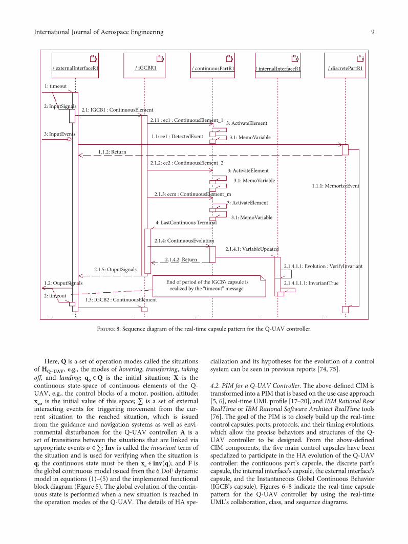
4.2. PIM for a Q-UAV Controller. The above-defined CIM istransformed into a PIM that is based on the use case approach[5, 6], real-time UML profile [17–20], and IBM Rational RoseRealTime or IBM Rational Software Architect RealTime tools[76]. The goal of the PIM is to closely build up the real-timecontrol capsules, ports, protocols, and their timing evolutions,which allow the precise behaviors and structures of the Q-UAV controller to be designed. From the above-definedCIM components, the five main control capsules have beenspecialized to participate in the HA evolution of the Q-UAVcontroller: the continuous part’s capsule, the discrete part’scapsule, the internal interface’s capsule, the external interface’scapsule, and the Instantaneous Global Continuous Behavior(IGCB’s capsule). Figures 6–8 indicate the real-time capsulepattern for the Q-UAV controller by using the real-timeUML’s collaboration, class, and sequence diagrams.
/ externalInterfaceR1
1: timeout
2: InputSignals
3: InputEvents
1.2: OuputSignals
1.3: IGCB2 : ContinuousElement
2.1.5: OuputSignals
2.1.4.2: Return
2.1.4: ContinuousEvolution
4: LastContinuous Terminal
2.1.3: ecm : ContinuousElement_m
2.1.2: ec2 : ContinuousElement_2
1.1: ee1 : DetectedEvent
2.11 : ec1 : ContinuousElement_1 3: ActivateElement
3.1: MemoVariable
1.1.1: MemorizeEvent
3: ActivateElement
3.1: MemoVariable
3.1: MemoVariable
2.1.4.1: VariableUpdated
2.1.4.1.1: Evolution : VerifyInvariant
2.1.4.1.1.1: InvariantTrue
3: ActivateElement
2.1: IGCB1 : ContinuousElement
1.1.2: Return
2: timeout
/ iGCBR1 / continuousPartR1 / internalInterfaceR1 / discretePartR1
End of period of the IGCB’s capsule isrealized by the “timeout” message.
Figure 8: Sequence diagram of the real-time capsule pattern for the Q-UAV controller.
9International Journal of Aerospace Engineering

In Figure 6, the discrete part’s capsule consists of thesituations Q and transitions A in the HA of the Q-UAVcontroller; the continuous part’s capsule contains the contin-uous state-space X; the IGCB’s capsule builds up concreteglobal continuous behaviors as f ∈ F, where f is derived fromequations (1)–(4) and the implemented functional block dia-gram (Figure 5) can be implemented in f for estimating thevalues of the position, altitude, attitude, and velocity of theQ-UAV; the internal interface’s capsule permits the Inv toolto generate internal events in the HA evolution; and theexternal interface’s capsule is an intermediary that receivesor sends episodic events and periodic signals between theQ-UAV controller and their interacting systems, such asthe AES and MDS.
In Figure 8, the messages exchanged between the maincontrol capsules, which are defined by the protocols(Figure 7), are synchronous, and the interval between twoadjacent timeout messages indicates the sampling period(ΔT) of the IGCB’s capsule. The external interface’s capsulereceives periodic signals coming from external continuouscomponents. It then gives the ContinuousElement messageto the IGCB’s capsule so that the IGCB’s capsule can call allof the continuous elements corresponding to the concrete
“IGCB:IGCB1.” During the call of the IGCB’s capsule, theexternal interface’s capsule can receive an event named“3: InputEvent” issued from the MDS or AES, and thisevent, named “ee1: DetectedEvent”, is given to the discretepart’s capsule. The discrete part’s capsule then memorizesand later processes this event. If the IGCB’s capsule receivesthe LastContinuousTerminal message coming from the con-tinuous part’s capsule, it gives the ContinuousEvolutionmes-sage to the continuous part’s capsule so that the internalinterface’s capsule can receive all updated variables. Theinternal interface’s capsule then verifies the invariant(xc ∈ invðqÞ) of the situation q2. In this case, there is a gener-ated internal event. The internal interface’s capsule gives thisevent to the discrete part’s capsule, which permits the IGCB’scapsule to identify the concrete “IGCB:IGCB2” and giveoutput signals to the external interface’s capsule. At theend of this sampling period, the external interface’s cap-sule gives the output event and control signals to theexternal environment of the Q-UAV operating with itsconcrete”IGCB:IGCB2.”
Tools such as HyTech, CheckMate, PHAver, and HSolver[77] can be used to test a hybrid automaton to verify the gen-erally dynamic behaviors of the Q-UAV controller. At this
Table 2: The main control capsules of PIM can be customized and reused in the new control application for various UAVs of the VerticalTake-Off and Landing (VTOL) type.
Designed control capsulesSpecialization rules
Generic artifacts Specialized artifacts
Discrete capsuleThe discrete part’s capsule is not
changed in the overall design of thenew controller of VTOL-type UAVs.
None
Continuous part
The ports and protocols of thiscapsule are not changed in the overalldesign of the new controller of VTOL
type UAVs.
The continuous part’s capsule is specialized bysupplementing or cutting down continuous
components (xc ∈X) that depend on the physicalactuators installed on the new VTOL-type UAV. Thestates and their behaviors, which correspond to thesupplemented/cut down continuous elements, are
supplemented/cut down in/from the state machine ofthis capsule. The behavior of the new set of continuouselements is used to redefine the concrete Instantaneous
Global Continuous Behaviors (IGCBs) (f ∈ F).
IGCB
The state machine, ports, and protocols ofthis capsule are not changed in the overall
design for the new controller of theVTOL-type UAV
The specifications of the IGCB’s capsule make up thenew IGCB model and are formed by restructuring the
new set of continuous elements according to theimplemented functional block diagram.
Internal interfaceThe state machine and ports of this capsuleare not changed in the overall design for thenew controller of the VTOL-type UAV.
The specialization of the internal interface’s capsule isperformed by supplementing/cutting down in/fromthe new IGCB in the IGCB’s capsule if necessary. Anew Inv term corresponds to new supplemented/cutdown situations in/from the discrete part’s capsule of
application.
External interfaceThe state machine, ports, and protocols of this capsule
are not changed in the overall design for the newcontroller of the VTOL-type UAV.
The external interface’s capsule is specialized bysupplementing or cutting down input or outputevents, which are issued from outside, (i.e.,
supplementing/cutting down these events in/fromits protocols).
The real-time capsule patterns shown in Figures 6–8 are not changed in the overall design for new controllers of VTOL-type UAVs.
10 International Journal of Aerospace Engineering
moment, formal tools, such as IBM Rational Test RealTime[76], also exist to directly test a capsule collaboration. Thistool permits us to validate a set of input sequences anddefined objects in order to make sure the behaviors of thesystem are well modeled. Moreover, we can find softwaretools such as IBM Rational Rose RealTime and IBM RationalSoftware Architect RealTime [76], which can be used tosupport the formal reuse of designed control components.They permit us to undergo reverse engineering of applica-tions to track the requirements of the developed systems. Inparticular, we can also use the SystemVerilog tool [58, 59]
and a novel NLP framework [60] to completely validate thecontrol requirements and design models of the developedsystem.
In addition, the reusability is very important when imple-menting controllers for different applications of UAVs of theVTOL type because it can reduce the development time andcost. The specializations, which permit the capsule collabora-tion of a developed Q-UAV to be customizable and reusablein the new control application for various UAVs of the VTOLtype, are summarized in Table 2.
4.3. PSM for a Q-UAV Controller. To realize and deploy theQ-UAV controller, the PIM is first implemented in thePSM (i.e., the simulation model) that is transformed fromthe above-built PIM by using tools such as the IBM RationalRose RealTime or IBM Rational Software Architect RealTime[76] or Papyrus for Real-Time (Papyrus-RT) [78] and Mode-lica/OpenModelica [21, 79]. Here, the IBM Rational providesa rich set of capabilities delivered as part of a collaborativeand integrated range of products to support the real-timeUML design of industrial software systems. Papyrus-RT isan industrial-grade, complete open-source modeling envi-ronment that is used for the development of complex, soft-ware-intensive, real-time, embedded, and cyber-physicalsystems. It acts as an implementation of the real-time UMLtogether with editors, a code generator for C++, and a sup-porting runtime system. In addition, OpenModelica is anopen-source modeling and simulation environment intendedfor industrial and academic usage. It is an object-orienteddeclarative multidomain modeling language that is used forcomplex dynamic systems. The OpenModelica environmentallows most of the expression, algorithm, and function partsof Modelica to be executed interactively, as well as equation
620.0 mm605.0 mm
1730.0 mm
495.
0 m
m11
36.0
mm
1030.0 mm
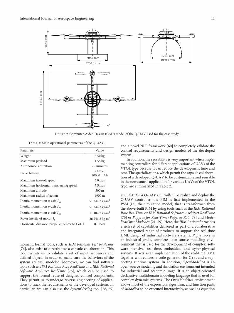
Figure 9: Computer-Aided Design (CAD) model of the Q-UAV used for the case study.
Table 3: Main operational parameters of the Q-UAV.
Parameter Value
Weight 4.50 kg
Maximum payload 1.55 kg
Autonomous duration 25 minutes
Li-Po battery22.2V,
20000mAh
Maximum take-off speed 5.0m/s
Maximum horizontal transferring speed 7.5m/s
Maximum altitude 500m
Maximum radius of action 4900m
Inertia moment on x-axis Ixx 51.34e-3 kg·m2
Inertia moment on y-axis Iyy 51.34e-3 kg·m2
Inertia moment on z-axis Izz 11.18e-2 kg·m2
Rotor inertia of motor Jr 36.24e-5 kg·m2
Horizontal distance: propeller center to CoG l 0.515m
11International Journal of Aerospace Engineering

models and Modelica functions to be compiled into efficientC/C++ codes. The simulation results in OpenModelica allowus to theoretically assess the control performance and tochoose the properties of control elements before they aredeployed.
In this study, the PIM with optimized control elements inthe simulation model was updated to obtain a new PIM forthe deployment model of Q-UAV called PIM+. Finally, thisPIM+ was transformed into the new PSM+ (i.e., the realiza-tion model) by using various specific platforms based on
Step.zAltitude.z
z-a
ltitu
de (m
)
15
20
10
5
00 42 6 8 10
Time (s)
(a)
Step.xPosition.x
x-p
ositi
on (m
)
16
14
12
10
8
6
4
2
0
Time (s)0 1 2 3 4 5
(b)
Figure 10: Transient control responses in the z-direction (a) and x-direction (b).
12 International Journal of Aerospace Engineering

the object-oriented Implementation Development Environ-ment (IDE), e.g., the Arduino’s IDE [22], to construct a Q-UAV controller with compatible microcontrollers, e.g., theATMEGA32-U2 and STM32 Cortex-M4 microcontrollers[22]. The above PIM-PSM transformations were performedthrough round-trip engineering (i.e., forward and reverseengineering) of the intermediate C++ codes, includingabout 80% of the generated codes and 20% of the hand-crafted codes issued from the models depicted in IBMRational Rose RealTime or IBM Rational Software ArchitectRealTime or Papyrus-RT, OpenModelica tools, and theArduino’s IDE. The transformation rules that were usedto convert the PIM into the PSM or the PIM∗ into thePSM∗ and vice versa through the round-trip engineeringof the intermediate C++ codes can be found in the authors’reports [50, 74, 75].
In addition, the above-defined HA can be automaticallyimplemented by using the State pattern described in [80,81]. The State pattern represents either of the following cases:(i) an object’s behavior depends on its state, and the objectmust change its behavior at run-time depending on that state,and (ii) operations have large, multipart, conditional state-ments that depend on the object’s state. This state is usuallyrepresented by one or more enumerated constants. Often,several operations contain this same conditional structure.The State pattern puts each branch of the conditional struc-
ture in a separate class. This lets us treat the object’s state asan object in its own right that can vary independently fromother objects. Following this pattern, the detailed implemen-tation structure and codes of HA have been found in theauthor’s report [74] to enhance the significant programmingeffectiveness of the control program of Q-UAV.
5. Application
5.1. Physical System Configurations. Based on the above-proposed hybrid model, a trajectory-tracking controller thatpermits a low-cost Q-UAV to reach and follow the predeter-mined trajectory was developed. Figure 9 shows theComputer-Aided Design (CAD) model of this Q-UAV usedfor the case study. The main operational parameters of theQ-UAV are summarized in Table 3.
5.2. Results of Control Implementation. All elements of theanalysis and design models were created to allow the imple-mentation of the trajectory-tracking controller of this Q-UAV. Here, we present some of the control simulationresults that were obtained through the following simulationcases: the guidance system addressed a desired event of tak-ing-off to the Q-UAV with an altitude of 15m; the transientcontrol response in the z-direction is illustrated inFigure 10(a); Figure 10(b) shows the transient controlresponse in the x-direction when the Q-UAV received thedesired event of transferring with a desired distance of 15min the x-direction from the current position. All of theobtained simulation results allow the control performanceof the system to be assessed theoretically within the controlcriteria such as the admissible timing response, the transi-tion, and static errors. The assessed simulation results per-mitted us to choose the designed control elements and theirproperties that were used to perform the deployment phase.
In this case study, the defined state-space models pre-sented in equation systems (4) and (5) were implementedby the UKF algorithm (Algorithm 1) to predict the motion
Figure 11: Installation and trial flights for the Q-UAV controller.
�e desiredtrajectory
19.97 0.16
0.16 179.71
�e reachedtrajectory 23
1Home4
Figure 12: The Q-UAV reached and followed a desired polygon-shaped trajectory with heading angles of about 90° and 110°.
Autolanding
Figure 13: Trial VTOL for the Q-UAV.
13International Journal of Aerospace Engineering

states corresponding to the sensors installed on this Q-UAV,such as the IMU MPU6000 with a working frequency of100Hz [23] and the GPS Ublox Neo 6M with a workingfrequency of 10Hz [24]. The ATMEGA32-U2 and STM32Cortex-M4 microcontrollers [22] were used on the mainboard, and the control program was installed with Arduino’sIDE [22] based on C++ language. The Q-UAV installationfor trial flights is shown in Figure 11.
The main test cases and obtained results for the Q-UAVare illustrated and were used to assess the control perfor-mance of this Q-UAV as follows:
(i) First test scenario: the Q-UAV autonomouslyreached and followed a desired polygon-shaped tra-jectory with heading angles of about 90° and 110°
and an average velocity of 2.5m/s (Figure 12). Themaximum trajectory error was about 1.40m againsteach Way-Point (WP) position at these headingangles.
(ii) Second test case: the Q-UAV was capable of VerticalTake-Off and Landing (VTOL) with a maximumaltitude of 480m (Figure 13); the landed positionerror was 0.30m against the initial take-off position
(iii) Third test scenario: the Q-UAV autonomouslyreached and followed a desired zigzag-lined trajec-tory with various heading angles and an averagevelocity of 2.5m/s (Figure 14). The maximum trajec-tory error was about 1.20m against each WP posi-tion at these heading angles
Following the comparison between the above-obtainedexperimental data and the existing experimental resultspresented in [74], in which the EKF algorithm was used toimplement the same physical Q-UAV model, thetrajectory-tracking controller of this Q-UAV had animproved stabilized trajectory error, which decreased byabout 0.2–0.4m. From this case, we also found that the
UKF can provide considerable improvement over the EKFin the control implementation for VTOL-type UAVs.
6. Conclusions and Future Work
This paper presented a hybrid control that can be used toconveniently realize controllers for Q-UAVs whose globalbehaviors mean that they can be considered industrial HDSs(IHDSs). This model is mainly based on the specialization ofMDA/MBSE features combined with the real-time UML/-SysML, UKF algorithm, and HA to closely implement andrealize the control parts of the system. The Q-UAV dynamicsand control architecture were firstly adapted for the controland combined with the specialization of MDA/MBSEfeatures including the CIM, PIM, and PSM components. Inthe CIM, the use case model was specialized with continuousbehaviors, the UKF algorithm, and HA to closely capture therequirements of the analysis for a Q-UAV controller. ThePIM was built to obtain a detailed design model by specifyingthe control capsules, ports, and protocols enclosed with theirtiming evolutions in order to model the behaviors and struc-tures of the Q-UAV controllers in detail. The designed PIMcomponents were also used to create a real-time capsulepattern that can be customized and reused in new UAVapplications, of which operating modes are capable of VTOL,hovering, and horizontal flight. The updated PIM with theoptimized control elements of the simulation model (PIM+)was then transformed into PSM+ through the round-tripengineering of the intermediate C++ codes in order to forma Q-UAV controller with compatible microcontrollers. Basedon this proposed hybrid control model, a trajectory-trackingcontroller of a low-cost quadrotor UAV was deployed andtested out on the Arduino ATMEGA U2 and STM32-Cor-tex-M4 microcontrollers.
Furthermore, the above-developed control applicationconfirms that the MDA/MBSE approach combined with thereal-time UML/SysML provides a framework for, and enables,tools to be provided to specify a system independently of the
�e reachedtrajectory
1
2 3 6
4 5
7
8 9
10
11
Home
�e desiredtrajectory
Figure 14: The Q-UAV reached and followed a desired zigzag-lined trajectory.
14 International Journal of Aerospace Engineering

platform that supports it, specify platforms, choose a partic-ular platform for the system, and transform the system’sspecifications into one for a particular platform. However,the real-time UML/SysML versions lack the constructsrequired for modeling internal continuous behaviors foreach state on the state machine diagram, so an implementedfunctional block diagram must then be defined in the CIMto model continuous behaviors for industrial HDSs such asthe Q-UAV controller with events issued from outside.
We only applied the above-proposed control model inthe low-cost Q-UAV controller and intend to implement itin new control applications for autonomous coordinatedvehicles. Eventually, if we get positive feedback, we will inves-tigate our application strategy to make it more effective. Thiswill permit us to create controllers to effectively balance thesearch and target response in cooperative teams of aVTOL-type UAV with an unmanned ship and multipleautonomous underwater vehicles for ocean exploration. Thiswill be specialized with design and verification models ofsafety-critical systems, as indicated by [58–60].
Abbreviations
CIM: Computation Independent ModelMDE: Model-Driven EngineeringCLF: Control Lyapunov FunctionsNLP: Natural Language ProcessingDoF: Degrees of FreedomOMG: Object Management GroupGPS: Global Positioning SystemPID: Proportional–Integral–DerivativeHA: Hybrid automataPIM: Platform Independent ModelHDS: Hybrid Dynamic SystemsPSM: Platform Specific ModelIB: Integral BacksteppingQ-UAV: Quadrotor Unmanned Aerial VehiclesIDE: Implementation Development EnvironmentSDLC: System Development Life CycleIGCB: Instantaneous Global Continuous BehaviorSMC: Sliding-Mode ControlIMU: Inertial Measurement UnitSysML: System Modeling LanguageLQ: Linear QuadraticUKF: Unscented Kalman FilterLOS: Line-Of-SightUML: Unified Modeling LanguageMBSE: Model-Based Systems EngineeringUMLSV: UML profile for SystemVerilogMDA: Model-Driven ArchitectureWP: Way-Point.
Data Availability
No data were used to support this study.
Conflicts of Interest
The authors declare that they have no conflicts of interest.
Acknowledgments
This work was supported by the Centennial SIT Action forthe 100th anniversary of Shibaura Institute of Technology toenter the top ten Asian Institute of Technology.
References
[1] P. Radoglou-Grammatikis, P. Sarigiannidis, T. Lagkas, andI. Moscholios, “A compilation of UAV applications for preci-sion agriculture,” Computer Networks, vol. 172, article107148, 2020.
[2] R. Woellner and T. C. Wagner, “Saving species, time andmoney: application of unmanned aerial vehicles (UAVs) formonitoring of an endangered alpine river specialist in a smallnature reserve,” Biological Conservation, vol. 233, pp. 162–175, 2019.
[3] H. Shakhatreh, A. H. Sawalmeh, A. Al-Fuqaha et al.,“Unmanned aerial vehicles (UAVs): a survey on civil applica-tions and key research challenges,” IEEE Access, vol. 7,pp. 48572–48634, 2019.
[4] S. Friedenthal, A. Moore, and R. Steiner, A Practical Guide toSysML - the Systems Modeling Language, Elsevier, Waltham,MA, USA, 3rd edition, 2015.
[5] OMG, “Unified Modeling Language (UML® Version 2.5.1): aspecification defining a graphical language for visualizing,specifying, constructing, and documenting the artifacts of dis-tributed object systems,” 2017, https://www.omg.org/spec/UML/2.5.1.
[6] OMG, “SysML specifications version 1.6,” 2019, https://www.omg.org/spec/SysML/1.6.
[7] OMG, “Model Driven Architecture (MDA): guide revision 2.0of MDA guide,” 2014, https://www.omg.org/mda.
[8] OMG, “The architecture of choice for a changing world: suc-cess atories,” 2020, http://www.omg.org/mda/products_success.htm.
[9] INCOSE, Systems Engineering Vision 2025, INCOSE, SanDiego, CA, USA, 2014.
[10] INCOSE, “Object-oriented systems engineering method,”2019, https://www.incose.org/incose-member-resources/working-groups/transformational/object-oriented-se-method.
[11] L. Ding and H. Wu, “Dynamical modelling and robust controlfor an unmanned aerial robot using hexarotor with 2-DOFmanipulator,” International Journal of Aerospace Engineering,vol. 2019, Article ID 5483073, 12 pages, 2019.
[12] K. Lu, C. Liu, C. Li, and R. Chen, “Flight dynamics modelingand dynamic stability analysis of tilt-rotor aircraft,” Interna-tional Journal of Aerospace Engineering, vol. 2019, Article ID5737212, 15 pages, 2019.
[13] X. Yao and Y. Yang, “Adaptive fault compensation and distur-bance suppression design for nonlinear systems with an air-craft control application,” International Journal of AerospaceEngineering, vol. 2020, Article ID 4531302, 16 pages, 2020.
[14] T. A. Henzinger, P. W. Kopke, A. Puri, and P. Varaiya, “What'sdecidable about hybrid automata?,” Journal of Computer andSystem Sciences, vol. 57, no. 1, pp. 94–124, 1998.
[15] P. G. Diem, An object-oriented design method for controllers ofquadrotor unmanned aerial vehicles (UAV), [Ph.D. Thesis],Hanoi University of Science and Technology, Vietnam, 2017.
15International Journal of Aerospace Engineering

[16] N. V. Hien and T. Soriano, “Implementing hybrid automatafor developing industrial control systems,” in Proceedings of8th IEEE-ETFA, pp. 129–137, Antibes - Juan les Pins, France,2001.
[17] OMG, “UML profile for MARTE: UML for model-drivendevelopment of real time and embedded systems (RTES),”2019, https://www.omg.org/spec/MARTE.
[18] B. P. Douglass, Real-Time UML Workshop for Embedded Sys-tems, Elsevier, Oxford, UK, 2nd edition, 2014.
[19] B. Selic and S. Gerard,Modeling and Analysis of Real-Time andEmbedded Systems with UML and MARTE, Elsevier, USA,2014.
[20] B. Selic, “Using UML for modeling complex real-time sys-tems,” vol. 1474 of Lecture Notes in Computer Science, ,Springer, 1998.
[21] OpenModelica, “OpenModelica Software, Version 1.14,” Janu-ary 2020, https://www.openmodelica.org.
[22] Arduino, “Open-source electronics prototyping platform forhardware and software,” December 2019, https://www.arduino.cc.
[23] InvenSense, “Sensor system on chip,” February 2020, https://invensense.tdk.com.
[24] u-blox, “Global leader in wireless communications and posi-tioning semiconductors and modules for the industrial, auto-motive and consumer markets,” December 2019, https://www.u-blox.com/en.
[25] N. Van Hien, N. Van He, and P. G. Diem, “A model-drivenimplementation to realize controllers for autonomous under-water vehicles,” Applied Ocean Research, vol. 78, pp. 307–319, 2018.
[26] Z. Wang, J. Yu, S. Lin, J. Dong, and Z. Yu, “Distributed robustadaptive fault-tolerant mechanism for quadrotor UAV real-time wireless network systems with random delay and packetloss,” IEEE Access, vol. 7, pp. 134055–134062, 2019.
[27] Z. Fu, J. Yu, G. Xie, Y. Chen, and Y. Mao, “A heuristic evolu-tionary algorithm of UAV path planning,”Wireless Communi-cations and Mobile Computing, vol. 2018, Article ID 2851964,11 pages, 2018.
[28] C. Zhu and Z. Guo, “Design of head-pursuit guidance lawbased on backstepping sliding mode control,” InternationalJournal of Aerospace Engineering, vol. 2019, Article ID8214042, 18 pages, 2019, 2019.
[29] Z. Chen and H. Jia, “Design of flight control system for a noveltilt-rotor UAV,” Complexity, vol. 2020, Article ID 4757381, 14pages, 2020.
[30] X. Liu and X. Liang, “Integrated guidance and control ofinterceptor missile based on asymmetric barrier Lyapunovfunction,” International Journal of Aerospace Engineering,vol. 2019, Article ID 8531584, 17 pages, 2019.
[31] Q. Xu, Z. Wang, and Z. Zhen, “Information fusion estimation-based path following control of quadrotor UAVs subjected toGaussian random disturbance,” ISA Transactions, vol. 99,pp. 84–94, 2020.
[32] Y. Huang, W. Liu, B. Li, Y. Yang, and B. Xiao, “Finite-time for-mation tracking control with collision avoidance for quadrotorUAVs,” Journal of the Franklin Institute, vol. 357, no. 7,pp. 4034–4058, 2020.
[33] J. Muliadi and B. Kusumoputro, “Neural network control sys-tem of UAV altitude dynamics and its comparison with thePID control system,” Journal of Advanced Transportation,vol. 2018, Article ID 3823201, 18 pages, 2018.
[34] R. Miranda-Colorado and L. T. Aguilar, “Robust PID controlof quadrotors with power reduction analysis,” ISA Transac-tions, vol. 98, pp. 47–62, 2020.
[35] A. A. Najm and I. K. Ibraheem, “Nonlinear PID controllerdesign for a 6-DOF UAV quadrotor system,” Engineering Sci-ence and Technology, an International Journal, vol. 22, no. 4,pp. 1087–1097, 2019.
[36] L. Martins, C. Cardeira, and P. Oliveira, “Linear quadratic reg-ulator for trajectory tracking of a quadrotor,” IFAC-PapersOn-Line, vol. 52, no. 12, pp. 176–181, 2019.
[37] H. I. Lee, D. W. Yoo, B. Y. Lee et al., “Parameter-robust linearquadratic Gaussian technique for multi-agent slung loadtransportation,” Aerospace Science and Technology, vol. 71,pp. 119–127, 2017.
[38] P. Bader, S. Blanes, and E. Ponsoda, “Structure preserving inte-grators for solving (non-)linear quadratic optimal controlproblems with applications to describe the flight of a quadro-tor,” Journal of Computational and Applied Mathematics,vol. 262, pp. 223–233, 2014.
[39] Y. Liu, J. Ma, and H. Tu, “Robust command filtered adaptivebackstepping control for a quadrotor aircraft,” Journal of Con-trol Science and Engineering, vol. 2018, Article ID 1854648, 9pages, 2018.
[40] Z. Chen, K. Niu, and L. Li, “Research on adaptive trajectorytracking algorithm for a quadrotor based on backstepping andthe sigma-pi neural network,” International Journal of Aero-space Engineering, vol. 2019, Article ID 1510341, 9 pages, 2019.
[41] R. Wang and J. Liu, “Trajectory tracking control of a 6-DOFquadrotor UAV with input saturation via backstepping,” Jour-nal of the Franklin Institute, vol. 355, no. 7, pp. 3288–3309,2018.
[42] M. Labbadi and M. Cherkaoui, “Robust adaptive backsteppingfast terminal sliding mode controller for uncertain quadrotorUAV,” Aerospace Science and Technology, vol. 93, article105306, 2019.
[43] M. Labbadi and M. Cherkaoui, “Robust integral terminal slid-ing mode control for quadrotor UAV with external distur-bances,” International Journal of Aerospace Engineering,vol. 2019, Article ID 2016416, 10 pages, 2019.
[44] T. Kusznir and J. Smoczek, “Sliding Mode-Based Control of aUAV Quadrotor for Suppressing the Cable- Suspended Pay-load Vibration,” Journal of Control Science and Engineering,vol. 2020, Article ID 5058039, 12 pages, 2020.
[45] T. Huang, D. Huang, Z. Wang, and A. Shah, “Robust trackingcontrol of a quadrotor UAV based on adaptive sliding modecontroller,” Complexity, vol. 2019, Article ID 7931632, 15pages, 2019.
[46] M. E. Antonio-Toledo, E. N. Sanchez, A. Y. Alanis, J. A. Flórez,and M. A. Perez-Cisneros, “Real-time integral backsteppingwith sliding mode control for a quadrotor UAV,” IFAC-Paper-sOnLine, vol. 51, no. 13, pp. 549–554, 2018.
[47] M. Labbadi and M. Cherkaoui, “Robust adaptive nonsingularfast terminal sliding-mode tracking control for an uncertainquadrotor UAV subjected to disturbances,” ISA Transactions,vol. 99, pp. 290–304, 2020.
[48] D. J. Almakhles, “Robust backstepping sliding mode controlfor a quadrotor trajectory tracking application,” IEEE Access,vol. 8, pp. 5515–5525, 2020.
[49] S. Li, Y. Wang, J. Tan, and Y. Zheng, “Adaptive RBFNNs/inte-gral sliding mode control for a quadrotor aircraft,” Neurocom-puting, vol. 216, pp. 126–134, 2016.
16 International Journal of Aerospace Engineering

[50] T. Soriano, N. V. Hien, K. M. Tuan, and T. V. Anh, “An object-unified approach to develop controllers for autonomousunderwater vehicles,”Mechatronics - The Science of IntelligentMachines, vol. 35, pp. 54–70, 2016.
[51] S. K. V. Ragavan, M. Shanmugavel, V. Ganapathy, andB. Shirinzadeh, “Unified meta-modeling framework usingbond graph grammars for conceptual modeling,” Roboticsand Autonomous Systems, vol. 72, pp. 114–130, 2015.
[52] F. Herrera, H. Posadas, P. Peñil et al., “The COMPLEXmethodology for UML/MARTE modeling and design spaceexploration of embedded systems,” Journal of Systems Archi-tecture, vol. 60, no. 1, pp. 55–78, 2014.
[53] L. T.W. Agner, I. W. Soares, P. C. Stadzisz, and J. M. Simão, “ABrazilian survey on UML and model-driven practices forembedded software development,” Journal of Systems and Soft-ware, vol. 86, no. 4, pp. 997–1005, 2013.
[54] M. Rashid, M. W. Anwar, and A. M. Khan, “Toward the toolsselection in model based system engineering for embeddedsystems–A systematic literature review,” Journal of Systemsand Software, vol. 106, pp. 150–163, 2015.
[55] F. Ciccozzi, I. Malavolta, and B. Selic, “Execution of UMLmodels: a systematic review of research and practice,” Software& Systems Modeling, vol. 18, no. 3, pp. 2313–2360, 2019.
[56] L. O. Freire, L. M. Oliveira, R. T. S. Vale et al., “Development ofan AUV control architecture based on systems engineeringconcepts,” Ocean Engineering, vol. 151, pp. 157–169, 2018.
[57] M. Rashid, M. W. Anwar, F. Azam, and M. Kashif, “Model-based requirements and properties specifications trends forearly design verification of embedded systems,” in Proceedingsof 11th System of Systems Engineering Conference (SoSE),pp. 1–7, Kongsberg, Norway, 2016.
[58] M. W. Anwar, M. Rashid, F. Azam, and M. Kashif, “Model-based design verification for embedded systems throughSVOCL: an OCL extension for SystemVerilog,” Design Auto-mation for Embedded Systems, vol. 21, no. 1, pp. 1–36, 2017.
[59] M. W. Anwar, M. Rashid, F. Azam, M. Kashif, and B. Butt, “Amodel-driven framework for design and verification of embed-ded systems through SystemVerilog,” Design Automation forEmbedded Systems, vol. 23, no. 3-4, pp. 179–223, 2019.
[60] M. W. Anwar, I. Ahsan, F. Azam, H. W. Butt, and M. Rashid,“A natural language processing (NLP) framework for embed-ded systems to automatically extract verification aspects fromtextual design requirements,” in Proceedings of 12th Interna-tional Conference on Computer and Automation Engineering,pp. 7–12, Sydney, Australia, 2020.
[61] R. C. Nelson, Flight Stability and Automatic Control, McGrawHill, Singapore, 2nd edition, 1998.
[62] K. P. Valavanis and G. J. Vachtsevanos, Eds., Handbook ofUnmanned Aerial Vehicles, Springer, Dordrecht, Heidelberg,New York, London, 2015.
[63] B. B. Kocer, T. Tjahjowidodo, and G. G. L. Seet, “Model predic-tive UAV-tool interaction control enhanced by externalforces,” Mechatronics, vol. 58, pp. 47–57, 2019.
[64] J. Huang, H. Zhang, G. Tang, and W. Bao, “Profile-tracking-based adaptive guidance law against maneuvering targets,”International Journal of Aerospace Engineering, vol. 2019,Article ID 8056342, 17 pages, 2019.
[65] E. A. Wan and R. V. D. Merwe, “The unscented Kalman filter,”in Kalman Filtering and Neural Networks, S. Haykin, Ed.,pp. 221–280, Wiley, New York, USA, 2001.
[66] Y. Bar-Shalom, X. R. Li, and T. Kirubarajan, Estimation withApplications to Tracking and Navigation- Theory Algorithmsand Software, Wiley & Sons, USA, 2001.
[67] A. M. Lekkas and T. I. Fossen, “Integral LOS path followingfor curved paths based on a monotone cubic Hermite splineparametrization,” IEEE Transactions on Control SystemsTechnology, vol. 22, no. 6, pp. 2287–2301, 2014.
[68] H. Choset, K. M. Lynch, S. Hutchinson et al., Principles ofRobot Motion: Theory, Algorithms, and Implementation, theMIT Press, Cambridge, MA, USA; London, UK, 2005.
[69] J. H. Liu, J. Y. Shan, and Q. Liu, “Optimal pulsed guidancelaw with terminal impact angle constraint,” Proceedings ofthe Institution of Mechanical Engineers, Part G: Journal ofAerospace Engineering, vol. 231, pp. 1993–2005, 2016.
[70] Z. Zheng and Y. Zou, “Adaptive integral LOS path followingfor an unmanned airship with uncertainties based on robustRBFNN backstepping,” ISA Transactions, vol. 65, pp. 210–219, 2016.
[71] L. Béla and M. Lorinc, Nonlinear Control of Vehicles andRobots, Springer, UK, 2011.
[72] M. Bouchoucha, S. Seghour, H. Osmani, and M. Bouri, “Inte-gralbackstepping for tracking of a System,” Electronics andElectrical Engineering, vol. 116, no. 10, pp. 75–80, 2011.
[73] J. J. Xiong and E. H. Zheng, “Position and attitude trackingcontrol for a quadrotor UAV,” ISA Transactions, vol. 53,no. 3, pp. 725–731, 2014.
[74] N. P. Hung, N. V. Hien, P. G. Diem et al., “Research on, designand manufacture a micro-unmanned aerial flying autono-mously at desired trajectories,” final report of research project,code: KC03.TN03/11-15, Hanoi University of Science andTechnology, Hanoi, Vietnam, 2013.
[75] N. V. Hien, L. T. Thai, V. T. Truong, P. G. Diem et al.,“Research, design and manufacture control systems with theintegration of object-oriented technology (MDA & Real-Time UML) and navigation units (INS/GPS) for autonomousunderwater vehicles,” final report of research project, fundedby the state, code: KC03.TN05/11-15; Hanoi University ofScience and Technology, Hanoi, Vietnam, 2013.
[76] IBM, “IBM rational software and training kit,” January 2020,https://my15.digitalexperience.ibm.com/b73a5759-c6a6-4033-ab6b-d9d4f9a6d65b/dxsites/151914d1-03d2-48fe-97d9-d21166848e65/academic/home.
[77] L. P. Carloni, R. Passerone, A. Pinto, and A. L. Sangiovanni-Vincentelli, Languages and Tools for Hybrid Systems Design,now Publishers Inc., Boston, MA, USA, 2006.
[78] Papyrus, “Eclipse Papyrus for Real-Time ("Papyrus-RT"),”February 2020, https://projects.eclipse.org/projects/polarsys.
[79] P. Fritzson, Principles of Object OrientedModeling and Simula-tion with Modelica 3.3: A Cyber-Physical Approach, Wiley &Sons, USA, 2011.
[80] E. Gamma, R. Helm, R. Johnson, and J. Vlissides, Design Pat-terns: Elements of Reusable Object-Oriented Software, Addi-son-Wesley, Oxford, UK, 1995.
[81] B. P. Douglass,Design Patterns for Embedded Systems in C - AnEmbedded Software Engineering Toolkit, Elsevier, Oxford, UK,1st edition, 2011.
17International Journal of Aerospace Engineering