ANNEXURE - I ESTABLISHMENT OF 5000 MT CAPACITY COLD … Amendment in respect of Cold Storage...
17
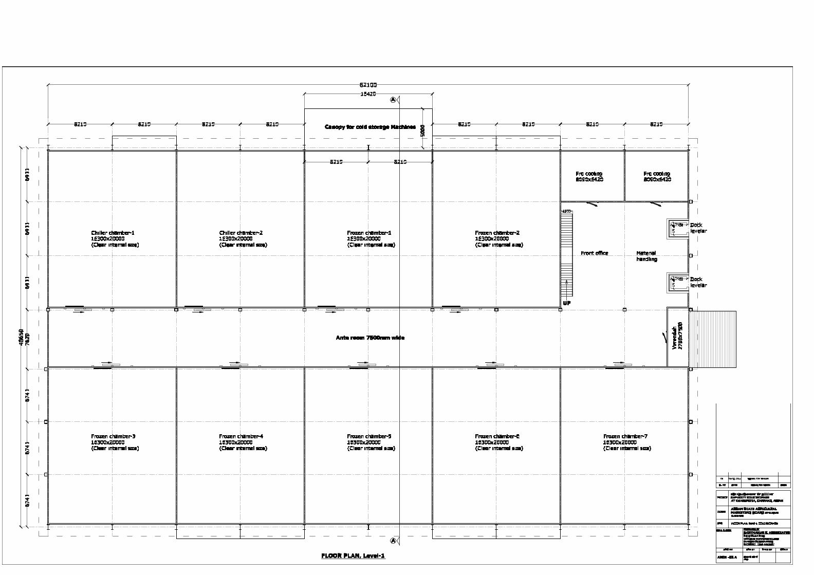
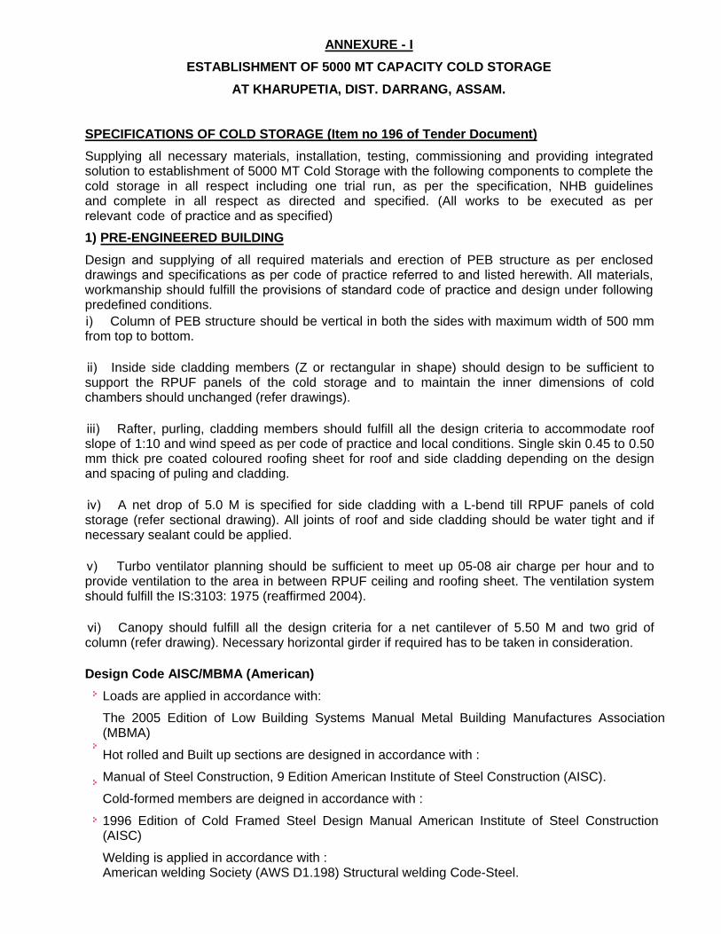
ANNEXURE - I ESTABLISHMENT OF 5000 MT CAPACITY COLD STORAGE AT KHARUPETIA, DIST. DARRANG, ASSAM. SPECIFICATIONS OF COLD STORAGE (Item no 196 of Tender Document) Supplying all necessary materials, installation, testing, commissioning and providing integrated solution to establishment of 5000 MT Cold Storage with the following components to complete the cold storage in all respect including one trial run, as per the specification, NHB guidelines and complete in all respect as directed and specified. (All works to be executed as per relevant code of practice and as specified) 1) PRE-ENGINEERED BUILDING Design and supplying of all required materials and erection of PEB structure as per enclosed drawings and specifications as per code of practice referred to and listed herewith. All materials, workmanship should fulfill the provisions of standard code of practice and design under following predefined conditions. i) Column of PEB structure should be vertical in both the sides with maximum width of 500 mm from top to bottom. ii) Inside side cladding members (Z or rectangular in shape) should design to be sufficient to support the RPUF panels of the cold storage and to maintain the inner dimensions of cold chambers should unchanged (refer drawings). iii) Rafter, purling, cladding members should fulfill all the design criteria to accommodate roof slope of 1:10 and wind speed as per code of practice and local conditions. Single skin 0.45 to 0.50 mm thick pre coated coloured roofing sheet for roof and side cladding depending on the design and spacing of puling and cladding. iv) A net drop of 5.0 M is specified for side cladding with a L-bend till RPUF panels of cold storage (refer sectional drawing). All joints of roof and side cladding should be water tight and if necessary sealant could be applied. v) Turbo ventilator planning should be sufficient to meet up 05-08 air charge per hour and to provide ventilation to the area in between RPUF ceiling and roofing sheet. The ventilation system should fulfill the IS:3103: 1975 (reaffirmed 2004). vi) Canopy should fulfill all the design criteria for a net cantilever of 5.50 M and two grid of column (refer drawing). Necessary horizontal girder if required has to be taken in consideration. Design Code AISC/MBMA (American) Loads are applied in accordance with: The 2005 Edition of Low Building Systems Manual Metal Building Manufactures Association (MBMA) Hot rolled and Built up sections are designed in accordance with : Manual of Steel Construction, 9 Edition American Institute of Steel Construction (AISC). Cold-formed members are deigned in accordance with : 1996 Edition of Cold Framed Steel Design Manual American Institute of Steel Construction (AISC) Welding is applied in accordance with : American welding Society (AWS D1.198) Structural welding Code-Steel.
Transcript of ANNEXURE - I ESTABLISHMENT OF 5000 MT CAPACITY COLD … Amendment in respect of Cold Storage...
ANNEXURE - I
ESTABLISHMENT OF 5000 MT CAPACITY COLD STORAGE
AT KHARUPETIA, DIST. DARRANG, ASSAM.
SPECIFICATIONS OF COLD STORAGE (Item no 196 of Tender Document)
Supplying all necessary materials, installation, testing, commissioning and providing integrated solution to establishment of 5000 MT Cold Storage with the following components to complete the cold storage in all respect including one trial run, as per the specification, NHB guidelinesand complete in all respect as directed and specified. (All works to be executed as per relevant code of practice and as specified)
1) PRE-ENGINEERED BUILDING
Design and supplying of all required materials and erection of PEB structure as per encloseddrawings and specifications as per code of practice referred to and listed herewith. All materials,workmanship should fulfill the provisions of standard code of practice and design under followingpredefined conditions.
i) Column of PEB structure should be vertical in both the sides with maximum width of 500 mmfrom top to bottom.
ii) Inside side cladding members (Z or rectangular in shape) should design to be sufficient tosupport the RPUF panels of the cold storage and to maintain the inner dimensions of coldchambers should unchanged (refer drawings).
iii) Rafter, purling, cladding members should fulfill all the design criteria to accommodate roofslope of 1:10 and wind speed as per code of practice and local conditions. Single skin 0.45 to 0.50mm thick pre coated coloured roofing sheet for roof and side cladding depending on the designand spacing of puling and cladding.
iv) A net drop of 5.0 M is specified for side cladding with a L-bend till RPUF panels of coldstorage (refer sectional drawing). All joints of roof and side cladding should be water tight and ifnecessary sealant could be applied.
v) Turbo ventilator planning should be sufficient to meet up 05-08 air charge per hour and toprovide ventilation to the area in between RPUF ceiling and roofing sheet. The ventilation systemshould fulfill the IS:3103: 1975 (reaffirmed 2004).
vi) Canopy should fulfill all the design criteria for a net cantilever of 5.50 M and two grid ofcolumn (refer drawing). Necessary horizontal girder if required has to be taken in consideration.
Design Code AISC/MBMA (American)
Loads are applied in accordance with:
The 2005 Edition of Low Building Systems Manual Metal Building Manufactures Association (MBMA)
Hot rolled and Built up sections are designed in accordance with :
Manual of Steel Construction, 9 Edition American Institute of Steel Construction (AISC).
Cold-formed members are deigned in accordance with :
1996 Edition of Cold Framed Steel Design Manual American Institute of Steel Construction (AISC)
Welding is applied in accordance with :American welding Society (AWS D1.198) Structural welding Code-Steel.
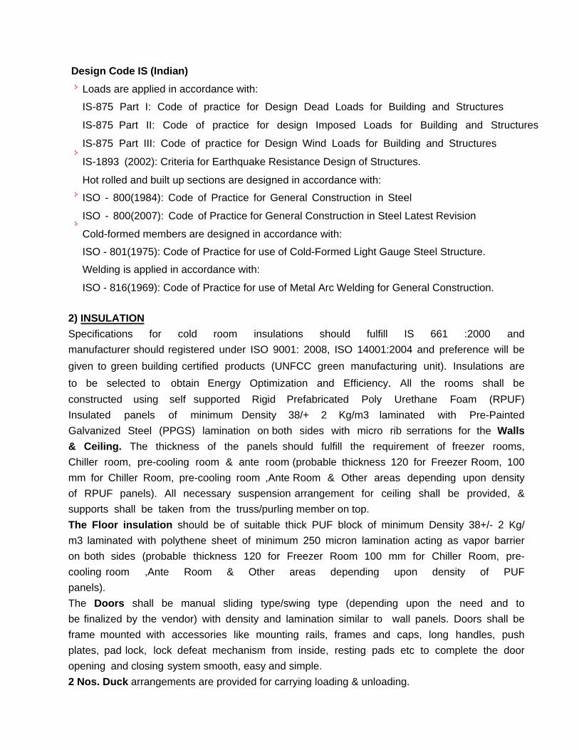
Design Code IS (Indian)
Loads are applied in accordance with:
IS-875 Part I: Code of practice for Design Dead Loads for Building and Structures
IS-875 Part II: Code of practice for design Imposed Loads for Building and Structures
IS-875 Part III: Code of practice for Design Wind Loads for Building and Structures
IS-1893 (2002): Criteria for Earthquake Resistance Design of Structures.
Hot rolled and built up sections are designed in accordance with:
ISO - 800(1984): Code of Practice for General Construction in Steel
ISO - 800(2007): Code of Practice for General Construction in Steel Latest Revision
Cold-formed members are designed in accordance with:
ISO - 801(1975): Code of Practice for use of Cold-Formed Light Gauge Steel Structure.
Welding is applied in accordance with:
ISO - 816(1969): Code of Practice for use of Metal Arc Welding for General Construction.
2) INSULATION
Specifications for cold room insulations should fulfill IS 661 :2000 and
manufacturer should registered under ISO 9001: 2008, ISO 14001:2004 and preference will be
given to green building certified products (UNFCC green manufacturing unit). Insulations are
to be selected to obtain Energy Optimization and Efficiency. All the rooms shall be
constructed using self supported Rigid Prefabricated Poly Urethane Foam (RPUF)
Insulated panels of minimum Density 38/+ 2 Kg/m3 laminated with Pre-Painted
Galvanized Steel (PPGS) lamination on both sides with micro rib serrations for the Walls
& Ceiling. The thickness of the panels should fulfill the requirement of freezer rooms,
Chiller room, pre-cooling room & ante room (probable thickness 120 for Freezer Room, 100
mm for Chiller Room, pre-cooling room ,Ante Room & Other areas depending upon density
of RPUF panels). All necessary suspension arrangement for ceiling shall be provided, &
supports shall be taken from the truss/purling member on top.
The Floor insulation should be of suitable thick PUF block of minimum Density 38+/- 2 Kg/
m3 laminated with polythene sheet of minimum 250 micron lamination acting as vapor barrier
on both sides (probable thickness 120 for Freezer Room 100 mm for Chiller Room, pre-
cooling room ,Ante Room & Other areas depending upon density of PUF
panels).
The Doors shall be manual sliding type/swing type (depending upon the need and to
be finalized by the vendor) with density and lamination similar to wall panels. Doors shall be
frame mounted with accessories like mounting rails, frames and caps, long handles, push
plates, pad lock, lock defeat mechanism from inside, resting pads etc to complete the door
opening and closing system smooth, easy and simple.
2 Nos. Duck arrangements are provided for carrying loading & unloading.

3) REFRIGERATION SYSTEM
The refrigeration system should be multi-compressor Freon Based Rack type system for cold rooms, freezer rooms and evaporator units located inside and should beconnected with interconnecting piping & cabling to condensing units as required. The basis of design for Ref system could be summarized as under:-
i) FREEZER ROOM : 2 Nos
Product to be stored: Frozen Products
Ambient Temperature 43 deg C
Room Sizes: As per Drawing
Wall lamination PPGS
Ceiling PPGS
Size of door 2400x3600 mm (Refer Reach Truck specifications also)
Storage Capacity: 5000 Kg Per Day
Pull down time 30.00 hrs.
Designed Specific heat (CP) 3kj/kg K
Designed Room Temperature: -20 Deg C (± 2 deg C)
Product Incoming Temperature: Incoming -12 Deg C and final -18 Deg C
Refrigeration system Rack Type
Type of cooling DX Type (Direct Expansion)
Capacity 14x2 kwt/room
Type of Refrigerant R404a
Type of Compressor Semi-hermetic (Frascold / BOCK / GIA make)
Type of Condenser Air Cooled (COMPAK ASP053)
Number of condensing unit 1 for 2 Rooms.
Model of Evaporator unit EUN14ZT or Similar
Number of Evaporator unit 2 X 14 Kwt. per room
Type of Evaporator unit Forced air cooled
MOC for Evaporator unit PPGS
Temperature indicator Micro processor based
De-frost system Electric and hot gas
Power Supply 415 V 50 Hz AC – 3 Phase.

ii) CHILLER ROOM : 7 Nos
Product to be stored: Frozen Products (Fruit & Vegetable)
Ambient Temperature 43 deg C
Room Sizes: As per Drawing
Wall lamination PPGS
Ceiling PPGS
Size of door 2400x3600 mm (Refer Reach Truck specifications also)
Storage Capacity: 5000 Kg Per Day.
Pull down time 24 hrs.
Designed Specific heat (CP) 3kj/kg K
Design Room Temperature: +2 Deg C
Product Incoming Temperature: Normal and Final 4 Deg C
Refrigeration system Split Type
Type of cooling DX Type (Direct Expansion)
Capacity 20x2 kwt/room
Refrigerant Freon (R404a)
Type of Compressor Semi-hermetic / SCROLL (Copeland or equivalent make)
Type of Condenser Air Cooled (COMPAK ASP070)
Number of condensing unit Total 4 Nos.
Model of Evaporator unit EUP20ZTHH
Number of Evaporator unit 2 X 14 Kwt. per room
Type of Evaporator unit Forced air cooled
MOC for Evaporator unit PPGS
Temperature indicator Micro processor based
De-frost system Electric and hot gas
Power Supply 415 V 50 Hz AC – 3 Phase
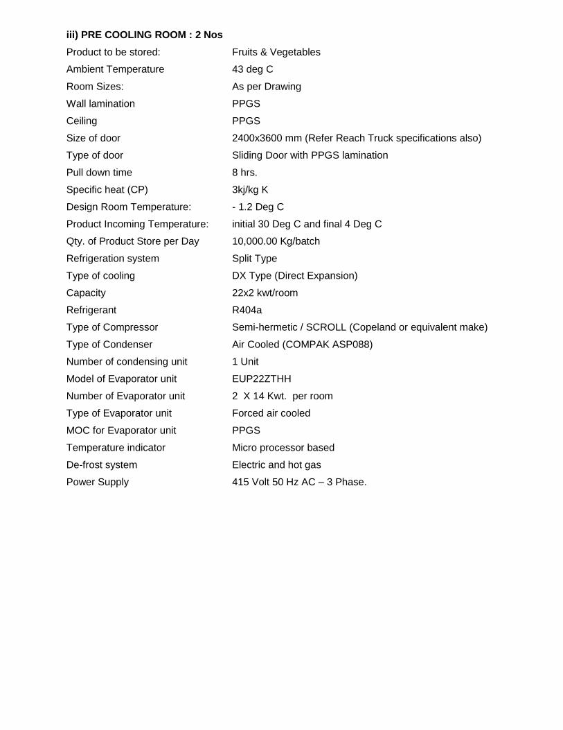
iii) PRE COOLING ROOM : 2 Nos
Product to be stored: Fruits & Vegetables
Ambient Temperature 43 deg C
Room Sizes: As per Drawing
Wall lamination PPGS
Ceiling PPGS
Size of door 2400x3600 mm (Refer Reach Truck specifications also)
Type of door Sliding Door with PPGS lamination
Pull down time 8 hrs.
Specific heat (CP) 3kj/kg K
Design Room Temperature: - 1.2 Deg C
Product Incoming Temperature: initial 30 Deg C and final 4 Deg C
Qty. of Product Store per Day 10,000.00 Kg/batch
Refrigeration system Split Type
Type of cooling DX Type (Direct Expansion)
Capacity 22x2 kwt/room
Refrigerant R404a
Type of Compressor Semi-hermetic / SCROLL (Copeland or equivalent make)
Type of Condenser Air Cooled (COMPAK ASP088)
Number of condensing unit 1 Unit
Model of Evaporator unit EUP22ZTHH
Number of Evaporator unit 2 X 14 Kwt. per room
Type of Evaporator unit Forced air cooled
MOC for Evaporator unit PPGS
Temperature indicator Micro processor based
De-frost system Electric and hot gas
Power Supply 415 Volt 50 Hz AC – 3 Phase.

iv) ANTE ROOM:-Ambient Temperature [in °C] Designed Room Temperature[± 2 °C] Product to be storedProduct Incoming Temperature [°C] Pull down time [Hrs]Room SizeWall Lamination In/OutCeiling [In/Out]Size of DoorType of refrigeration systemType of CoolingCapacity of Refrigeration system [KW] Type of RefrigerantModel of Evaporator unitNo of EvaporatorElectrical Panel for Ref System Type of evaporator unitsMOC for evaporator units Temperature indicator cum controller Lighting Inside the roomsDefrost SystemPower Supply
43 Deg C Positive 2 Deg C Fruits &Vegetable Incoming at 30 Deg C, Final 4 Deg C 24 Hrs As per Drawing PPGS PPGS 2400 x 3600 mm (Refer Reach Truck specifications) Split Type DX Type (Direct Expansion) 40 KW R404a EUP10ZP Units 4Nos Working Inbuilt in the condensing unit Forced Air Cooled PPGS Microprocessor based Suitable for 5W /Sqmt Electric & Hot Gas 415 V 50 Hz AC 3 Phase
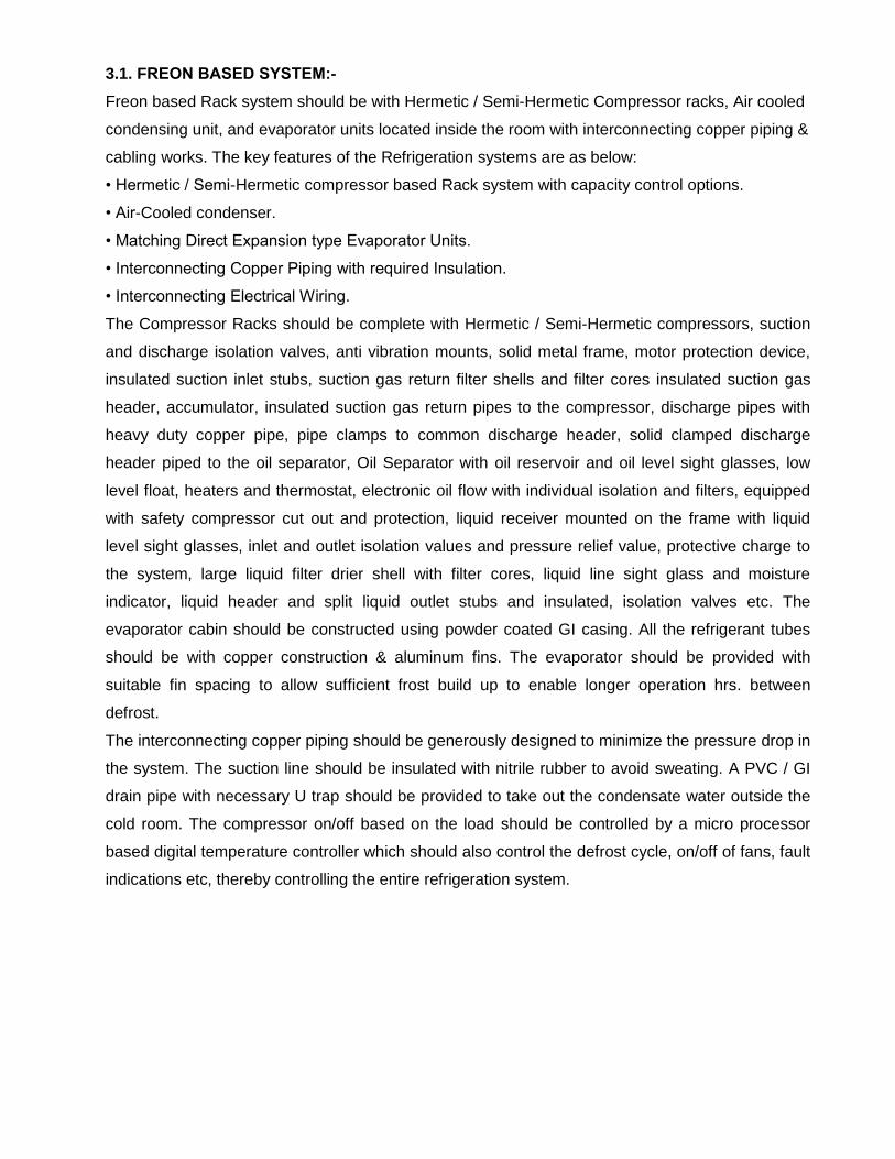
3.1. FREON BASED SYSTEM:-Freon based Rack system should be with Hermetic / Semi-Hermetic Compressor racks, Air cooled
condensing unit, and evaporator units located inside the room with interconnecting copper piping &
cabling works. The key features of the Refrigeration systems are as below:
• Hermetic / Semi-Hermetic compressor based Rack system with capacity control options.
• Air-Cooled condenser.
• Matching Direct Expansion type Evaporator Units.
• Interconnecting Copper Piping with required Insulation.
• Interconnecting Electrical Wiring.
The Compressor Racks should be complete with Hermetic / Semi-Hermetic compressors, suction
and discharge isolation valves, anti vibration mounts, solid metal frame, motor protection device,
insulated suction inlet stubs, suction gas return filter shells and filter cores insulated suction gas
header, accumulator, insulated suction gas return pipes to the compressor, discharge pipes with
heavy duty copper pipe, pipe clamps to common discharge header, solid clamped discharge
header piped to the oil separator, Oil Separator with oil reservoir and oil level sight glasses, low
level float, heaters and thermostat, electronic oil flow with individual isolation and filters, equipped
with safety compressor cut out and protection, liquid receiver mounted on the frame with liquid
level sight glasses, inlet and outlet isolation values and pressure relief value, protective charge to
the system, large liquid filter drier shell with filter cores, liquid line sight glass and moisture
indicator, liquid header and split liquid outlet stubs and insulated, isolation valves etc. The
evaporator cabin should be constructed using powder coated GI casing. All the refrigerant tubes
should be with copper construction & aluminum fins. The evaporator should be provided with
suitable fin spacing to allow sufficient frost build up to enable longer operation hrs. between
defrost.
The interconnecting copper piping should be generously designed to minimize the pressure drop in
the system. The suction line should be insulated with nitrile rubber to avoid sweating. A PVC / GI
drain pipe with necessary U trap should be provided to take out the condensate water outside the
cold room. The compressor on/off based on the load should be controlled by a micro processor
based digital temperature controller which should also control the defrost cycle, on/off of fans, fault
indications etc, thereby controlling the entire refrigeration system.
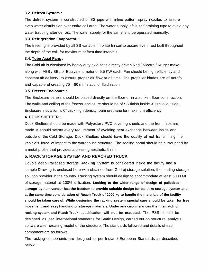
3.2. Defrost System :
The defrost system is constructed of SS pipe with inline pattern spray nozzles to assure
even water distribution over entire coil area. The water supply left is self draining type to avoid any
water trapping after defrost. The water supply for the same is to be operated manually.
3.3. Refrigeration Evaporator :
The freezing is provided by all SS variable fin plate fin coil to assure even frost built throughout
the depth of the coil, for maximum defrost time intervals.
3.4. Tube Axial Fans :
The Cold air is circulated by heavy duty axial fans directly driven Nadi/ Nicotra / Kruger make
along with ABB / BBL or Equivalent motor of 5.5 KW each. Fan should be high efficiency and
constant air delivery, to assure proper air flow at all time. The propeller blades are of aerofoil
and capable of creating 70 – 80 mm static for fluidization.
3.5. Freezer Enclosure :
The Enclosure panels should be placed directly on the floor or in a sunken floor construction.
The walls and ceiling of the freezer enclosure should be of SS finish inside & PPGS outside.
Enclosure insulation is 6” thick high density foam urethane for maximum efficiency.
4. DOCK SHELTER :
Dock Shelters should be made with Polyester / PVC covering sheets and the front flaps are
made. It should satisfy every requirement of avoiding heat exchange between inside and
outside of the Cold Storage. Dock Shelters should have the quality of not transmitting the
vehicle’s force of impact to the warehouse structure. The sealing portal should be surrounded by
a metal profile that provides a pleasing aesthetic finish.
5. RACK STORAGE SYSTEM AND REACHED TRUCK
Double deep Palletized storage Racking System is considered inside the facility and a
sample Drawing is enclosed here with obtained from Godrej storage solution, the leading storage
solution provider in the country. Racking system should design to accommodate at least 5000 Mt
of storage material at 100% utilization. Looking to the wider range of design of palletized
storage system vendor has the freedom to provide suitable design for palletize storage system and
at the same time consideration of Reach Truck of 2000 kg to handle the materials of the facility
should be taken care of. While designing the racking system special care should be taken for free
movement and easy handling of storage materials. Under any circumstances the mismatch of
racking system and Reach Truck specification will not be excepted. The PSS should be
designed as per international standards for Static Design, carried out on structural analysis
software after creating model of the structure. The standards followed and details of each
component are as follows:
The racking components are designed as per Indian / European Standards as described
below:
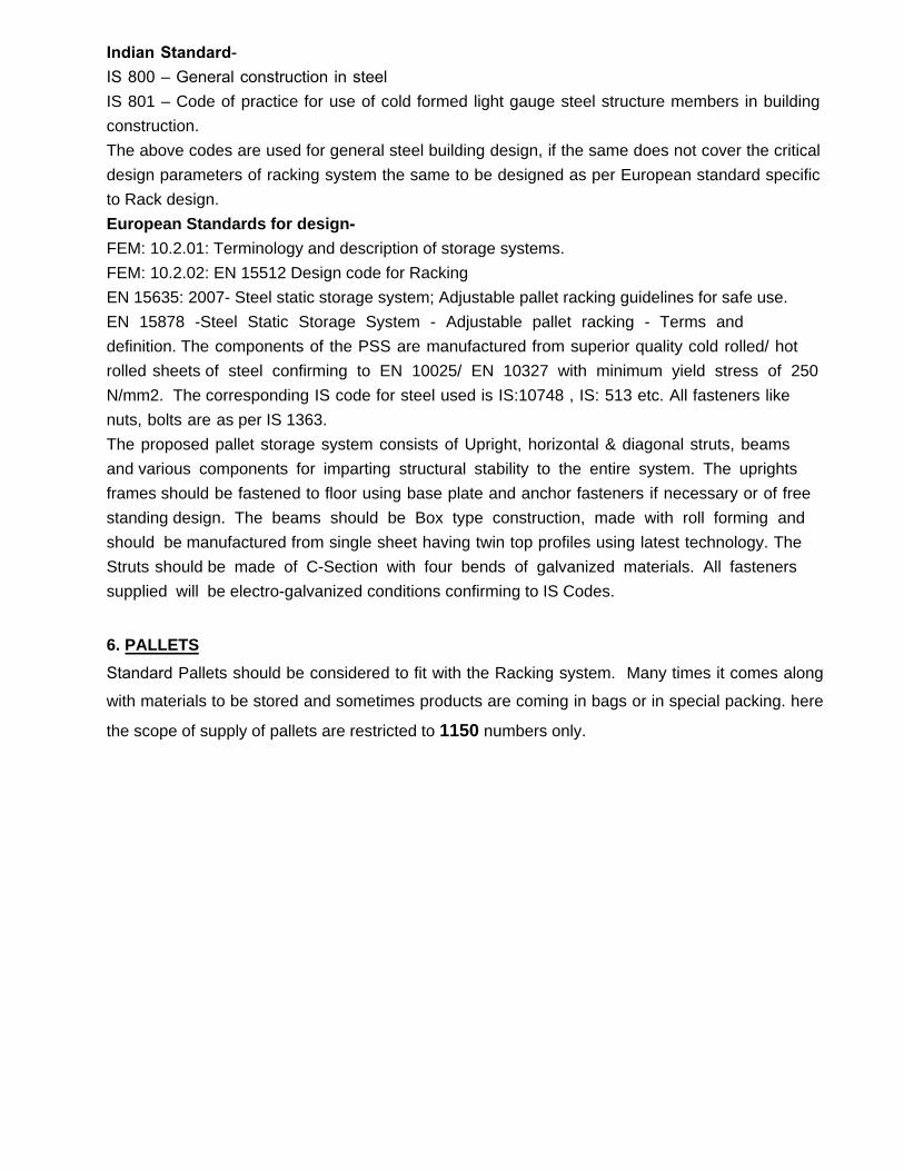
Indian Standard-IS 800 – General construction in steel IS 801 – Code of practice for use of cold formed light gauge steel structure members in building
construction.
The above codes are used for general steel building design, if the same does not cover the critical
design parameters of racking system the same to be designed as per European standard specific
to Rack design.
European Standards for design-FEM: 10.2.01: Terminology and description of storage systems.
FEM: 10.2.02: EN 15512 Design code for Racking
EN 15635: 2007- Steel static storage system; Adjustable pallet racking guidelines for safe use.
EN 15878 -Steel Static Storage System - Adjustable pallet racking - Terms and
definition. The components of the PSS are manufactured from superior quality cold rolled/ hot
rolled sheets of steel confirming to EN 10025/ EN 10327 with minimum yield stress of 250
N/mm2. The corresponding IS code for steel used is IS:10748 , IS: 513 etc. All fasteners like
nuts, bolts are as per IS 1363.
The proposed pallet storage system consists of Upright, horizontal & diagonal struts, beams
and various components for imparting structural stability to the entire system. The uprights
frames should be fastened to floor using base plate and anchor fasteners if necessary or of free
standing design. The beams should be Box type construction, made with roll forming and
should be manufactured from single sheet having twin top profiles using latest technology. The
Struts should be made of C-Section with four bends of galvanized materials. All fasteners
supplied will be electro-galvanized conditions confirming to IS Codes.
6. PALLETS
Standard Pallets should be considered to fit with the Racking system. Many times it comes along
with materials to be stored and sometimes products are coming in bags or in special packing. here
the scope of supply of pallets are restricted to 1150 numbers only.

Annexure - II
6. TECHNICAL SPECIFICATIONS FOR 2TON REACH TRUCK
● Capacity: 2000 Kgs @ L/C 600mm
● Lift Height: Depending upon the design of Racking system.
● Closed Mast Height: Depending upon the design of Racking system.
● Free Lift: Depending upon the design of Racking system.
● Residual Capacity: Depending upon the design of Racking system.
● Residual Capacity: Depending upon the design of Racking system.
● Battery : Suitable for the vehicle and as per code of Practice.
NOTE:The phrase "8.50 M lift height and" in Item No. 197 (Reach Truck 2 Ton:) of BOQis hereby deleted.
Annexure - III
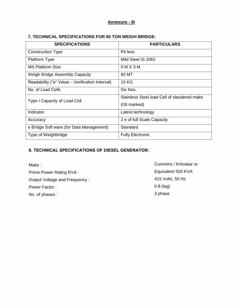
7. TECHNICAL SPECIFICATIONS FOR 60 TON WEIGH BRIDGE:
SPECIFICATIONS PARTICULARS
Construction Type Pit less
Platform Type Mild Steel IS 2062
MS Platform Size 9 M X 3 M
Weigh Bridge Assembly Capacity 60 MT
Readability (“e” Value – Verification Interval) 10 KG
No. of Load Cells Six Nos.
Type / Capacity of Load Cell Stainless Steel load Cell of slandered make
(ISI marked)
Indicator Latest technology
Accuracy 2 e of full Scale Capacity
e Bridge Soft ware (for Data Management) Standard
Type of Weighbridge Fully Electronic
8. TECHNICAL SPECIFICATIONS OF DIESEL GENERATOR:
Make :
Prime Power Rating KVA :
Output Voltage and Frequency :
Power Factor :
No. of phases :
Cummins / Kriloskar or
Equivalent 500 KVA
415 Volts, 50 Hz
0.8 (lag)
3 phase
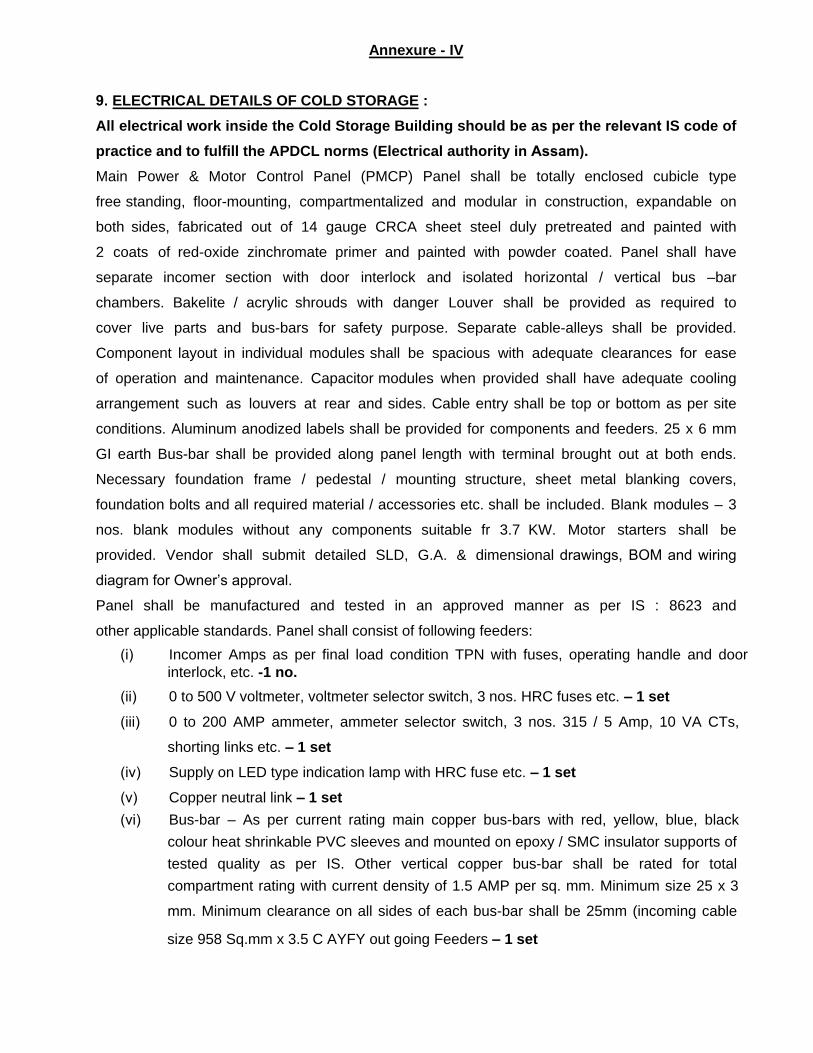
Annexure - IV
9. ELECTRICAL DETAILS OF COLD STORAGE :
All electrical work inside the Cold Storage Building should be as per the relevant IS code of
practice and to fulfill the APDCL norms (Electrical authority in Assam).Main Power & Motor Control Panel (PMCP) Panel shall be totally enclosed cubicle type
free standing, floor-mounting, compartmentalized and modular in construction, expandable on
both sides, fabricated out of 14 gauge CRCA sheet steel duly pretreated and painted with
2 coats of red-oxide zinchromate primer and painted with powder coated. Panel shall have
separate incomer section with door interlock and isolated horizontal / vertical bus –bar
chambers. Bakelite / acrylic shrouds with danger Louver shall be provided as required to
cover live parts and bus-bars for safety purpose. Separate cable-alleys shall be provided.
Component layout in individual modules shall be spacious with adequate clearances for ease
of operation and maintenance. Capacitor modules when provided shall have adequate cooling
arrangement such as louvers at rear and sides. Cable entry shall be top or bottom as per site
conditions. Aluminum anodized labels shall be provided for components and feeders. 25 x 6 mm
GI earth Bus-bar shall be provided along panel length with terminal brought out at both ends.
Necessary foundation frame / pedestal / mounting structure, sheet metal blanking covers,
foundation bolts and all required material / accessories etc. shall be included. Blank modules – 3
nos. blank modules without any components suitable fr 3.7 KW. Motor starters shall be
provided. Vendor shall submit detailed SLD, G.A. & dimensional drawings, BOM and wiring
diagram for Owner’s approval.
Panel shall be manufactured and tested in an approved manner as per IS : 8623 and
other applicable standards. Panel shall consist of following feeders:
(i) Incomer Amps as per final load condition TPN with fuses, operating handle and door
interlock, etc. -1 no.
(ii) 0 to 500 V voltmeter, voltmeter selector switch, 3 nos. HRC fuses etc. – 1 set
(iii) 0 to 200 AMP ammeter, ammeter selector switch, 3 nos. 315 / 5 Amp, 10 VA CTs,
shorting links etc. – 1 set
(iv) Supply on LED type indication lamp with HRC fuse etc. – 1 set
(v) Copper neutral link – 1 set
(vi) Bus-bar – As per current rating main copper bus-bars with red, yellow, blue, black
colour heat shrinkable PVC sleeves and mounted on epoxy / SMC insulator supports of
tested quality as per IS. Other vertical copper bus-bar shall be rated for total
compartment rating with current density of 1.5 AMP per sq. mm. Minimum size 25 x 3
mm. Minimum clearance on all sides of each bus-bar shall be 25mm (incoming cable
size 958 Sq.mm x 3.5 C AYFY out going Feeders – 1 set
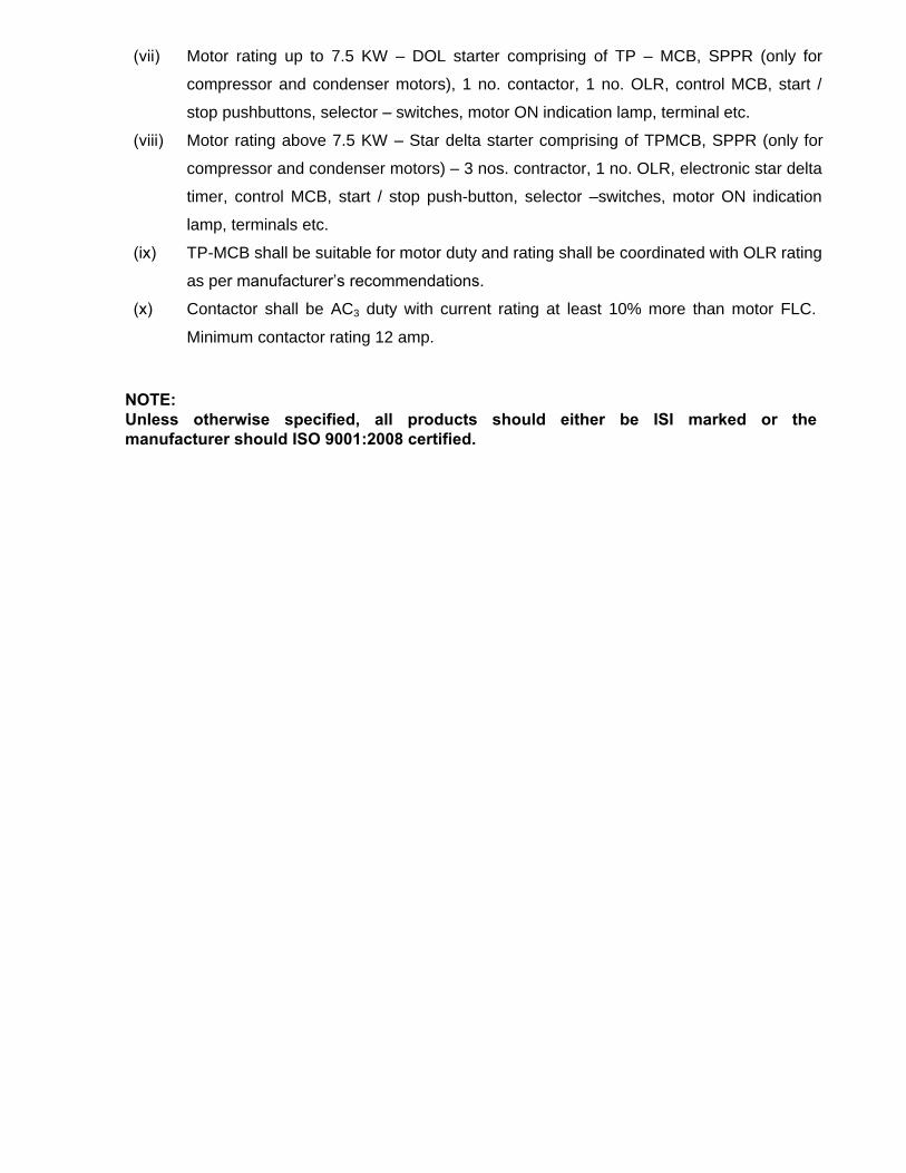
(vii) Motor rating up to 7.5 KW – DOL starter comprising of TP – MCB, SPPR (only for
compressor and condenser motors), 1 no. contactor, 1 no. OLR, control MCB, start /
stop pushbuttons, selector – switches, motor ON indication lamp, terminal etc.
(viii) Motor rating above 7.5 KW – Star delta starter comprising of TPMCB, SPPR (only for
compressor and condenser motors) – 3 nos. contractor, 1 no. OLR, electronic star delta
timer, control MCB, start / stop push-button, selector –switches, motor ON indication
lamp, terminals etc.
(ix) TP-MCB shall be suitable for motor duty and rating shall be coordinated with OLR rating
as per manufacturer’s recommendations.
(x) Contactor shall be AC3 duty with current rating at least 10% more than motor FLC.
Minimum contactor rating 12 amp.
NOTE:Unless otherwise specified, all products should either be ISI marked or the manufacturer should ISO 9001:2008 certified.