Annexure GS8 - Summary of the Operation of Coal Fired ...
49
Filed on behalf of (name & role of party) AGL Energy Limited Prepared by (name of person/lawyer) Liza Carver Law firm (if applicable) Ashurst Australia Tel +61 2 9258 5897 Fax +61 2 9258 6999 Email [email protected] Address for service (include state and postcode) Level 35, 225 George Street, Sydney, NSW, 2000 DX 388 Sydney [Form approved 01/08/2011] IN THE AUSTRALIAN COMPETITION TRIBUNAL AGL ENERGY LIMITED of 2014 RE: PROPOSED ACQUISITION OF MACQUARIE GENERATION (A CORPORATION ESTABLISHED UNDER THE ENERGY SERVICES CORPORATIONS ACT 1995 (NSW)) ANNEXURE CERTIFICATE This is the annexure marked "GS8" annexed to the statement of GLENN SCHUMACHER dated 23 March 2014 Annexure GS8
Transcript of Annexure GS8 - Summary of the Operation of Coal Fired ...

Filed on behalf of (name & role of party) AGL Energy Limited
Prepared by (name of person/lawyer) Liza Carver
Law firm (if applicable) Ashurst Australia
Tel +61 2 9258 5897 Fax +61 2 9258 6999
Email [email protected]
Address for service (include state and postcode)
Level 35, 225 George Street, Sydney, NSW, 2000 DX 388 Sydney
[Form approved 01/08/2011]
IN THE AUSTRALIAN COMPETITION TRIBUNAL
AGL ENERGY LIMITED
of 2014
RE: PROPOSED ACQUISITION OF MACQUARIE GENERATION (A CORPORATION ESTABLISHED UNDER THE ENERGY SERVICES CORPORATIONS ACT 1995 (NSW))
ANNEXURE CERTIFICATE
This is the annexure marked "GS8" annexed to the statement of GLENN SCHUMACHER dated
23 March 2014
Annexure GS8

Office Of The Chief Engineer
Project Hunter
Thermal Power Station Background(Black Coal Fired)Version 3 March 2014
1418

2
Office of the Chief Engineer – Thermal Power Station Background
This monograph deals with the typical design operation of coal fired (Thermal) central generating plant (power stations). The fuel type (black coal) and that fuel’s particular properties are critical to the consideration of the plant design and operation.
The basic concept of Thermal power stations is the conversion of chemical energy present in the fuel (in this case Black Coal) into electrical energy.
Even within broad fuel types such as ‘black coal’ there are a number of sub classifications such as Anthracite, Bituminous and Sub-Bituminous.
However, what is critical are the particular properties of each individual coal. Such properties include:
• Ash content (%);
• Moisture (%);
• Specific Energy (MJ/kg);
• Grindability (Hardgrove Grindability Index HGI);
• Abrasion Index;
• Ash Fusion Temperature and Slagging Index(s);
• Chemical composition of coal and ash.
Overview
Energy in Fuel Electrical Power
1419

3
Office of the Chief Engineer – Thermal Power Station Background
The performance of a particular coal is critical in both the design of new coal-fired boilers as well as existing steamraising plant. Coal is a naturally occurring material that is not homogeneous and changes within a single deposit iscommon. Thus, quality specifications are written by power stations to ensure that coal properties are within thosethat the plant can handle.
However, often issues of coal performance can be influenced by coal properties which are not generally specifiedby power stations. Thus, a knowledge of these more obscure coal facets are important in understanding problemsthat may arise in burning a particular coal. In addition, better understanding of coal properties and their effect oncoal performance in a particular plant may allow improved coal utilisation as well as open coal purchasing to awider array of coals.
Coal specifications typically include the following analysis:
Total Moisture – the total amount of water in the coal. The total moisture (water) has two components;1. inherent moisture; and 2. free or surface water. The inherent moisture is the water that is bound in the poresof the coal structure or chemically bonded to the coal.
Proximate Analysis – includes moisture (air dried), ash, volatile matter and fixed carbon.
Ultimate Analysis – gives the main organic constituents of the coal. These include carbon, hydrogen,nitrogen, sulphur and oxygen.
Specific Energy – (sometimes referred to as Heating Value), is the amount of heat that will be released perunit mass of coal when the coal is burnt.
Ash Analysis – aimed at finding the chemical composition of the ash constituents within the coal.
Ash Fusion Temperature (AFT) – are the temperatures at which various stages of melting of an ash pelletoccur. This measure has been traditionally a key indicator of the tendency for the coal to slag or foul a boilerfurnace and gas pass. However, it can be a poor indicator if used in isolation.
Hardgrove Grindability Index (HGI) – is an empirical measure of the grindability (the ease with which thecoal is reduced in size) of a coal.
Coal Performance
1420

4
Office of the Chief Engineer – Thermal Power Station Background
Coal specifications typically include the following analysis (Cont’d):
Forms of Sulphur – can indicate the existence of minerals such as pyrite (FeS2) which has significance on the coal behaviour in theboiler.
Abrasive Index (AI) – may indicate the tendency of the coal and its ash to wear components of the coal and ash handling plant aswell as the boiler and gas handling plant. A key element to be considered when examining a specific coal for its tendency to wear is theQuartz (SiO2) content.
Petrographic Analysis – is a microscopic examination of a coal to determine components of the coal that related to the originalorganic material from which the coal was formed. This has traditionally been a key tool for determining the "Rank” of the coal but, offersmany other possible applications in determining coal behaviour.
Trace Elements – chemical elements that are present in coal in very small proportions. However, their presence can have issues onboth coal performance and issues such as environmental effects.
Mineralogy of Coal & Ash – is the determination of what mineral “form” the chemical component of the coal and subsequent ashtake. This is an area which is now shedding a lot of light on a number of coal behaviours.
When considering coal analysis (specification) data, care should be taken to understand on what basis the data is presented. For exampleSpecific Energy (SE) or Heating Value can be reported on two basis: Gross SE (Higher HV) or Net SE (Lower HV) basis.
Coal properties can be quoted in four possible conditions:
Dry Ash Free (daf) – includes the fixed carbon and volatile matter;
Dry Basis (db) – includes fixed carbon, volatile matter and ash;
Air Dried Basis (adb) – includes fixed carbon, volatile matter, ash and air dried moisture;
As Received (ar) - includes fixed carbon, volatile matter, ash and air dried moisture and surface moisture.
Coal Specification
1421

5
Office of the Chief Engineer – Thermal Power Station Background
BROWN COAL
Fuel Type is Critical to Boiler Design and Size
1422

6
Office of the Chief Engineer – Thermal Power Station Background
Energy Conversion Process – Coal to Electricity
Typical Black Coal (PF) Fired Power Station Schematic.
1423

7
Office of the Chief Engineer – Thermal Power Station Background
Key Energy Conversion Process Elements
1424

8
Office of the Chief Engineer – Thermal Power Station Background
Energy Conversion Process – Coal to Electricity
1425

9
Office of the Chief Engineer – Thermal Power Station Background
Energy Conversion Process – Coal to Electricity
1426

10
Office of the Chief Engineer – Thermal Power Station Background
Energy Conversion Process – Coal Processing
Modern coal fired central generating plant (power stations) make use of a system called Pulverised Fuel [PF] (coal) firing system. Thepulverised (comminution) process is carried out on an on-demand basis by devices called pulverisers (or mills).
Despite current environmental concerns, coal remains an abundant and low cost fuel for power generation. Coal is burned to release thechemical energy that is stored within it. The heat energy released by the combustion of coal is released to water (and steam) in a boiler.The steam is then used to drive some arrangement of turbine(s) which in turn drive a generator. The combustion of coal can beundertaken in a number of ways depending upon the characteristics of the coal and the particular boiler application. However, pulverisedcoal (PF) firing – burning coal as a fine powder suspension in an open furnace – is the dominant method in use today for the generation ofelectricity in grid based power stations.
Pulverised coal was developed as early as the 1800s as a cost effective fuel for firing cement kilns replacing oil and gas. The earlypulverising systems were not considered reliable mainly due to the nature of the pulverising equipment then available. A number of meansof overcoming these problems were tried but their complexity on the whole the PF approach unattractive to steam generating plant. ThePF systems ability to produce dry coal with very good particle size control and uniform coal feed were recognised.
With a need for larger steam generating plant for electric power generation, the PF system offered the potential for scale up whilst stillimproving the combustion process. However, the existing boiler design and technology was a limiting factor. For PF firing applicationboilers, there was a need to modify the boiler furnace geometry. In the early 20th Century, changes in boiler design saw the expansion ofboiler fireboxes and crowded tube banks to allow the application of PF firing. Two key elements in the change to boiler design were theapplication of water-cooled furnaces and burner design advances to improve flame stability, provide better mixing, increase flametemperatures and improve combustion efficiency. These changes made advanced pulverised coal-fired systems possible in steamgeneration. Hand in hand with boiler design and construction went improvements in pulveriser design and reliability. This allowed directfiring PF systems that were both reliable and efficient.
PF: Pulverised Fuel.Note: In this paper, the terms; Pulverising, Milling andGrinding are considered as interchangeable. So too are the terms Pulveriser and Mill.
1427

11
Office of the Chief Engineer – Thermal Power Station Background
Energy Conversion Process – Coal to Electricity
1428

12
Office of the Chief Engineer – Thermal Power Station Background
Energy Conversion Process – Coal to Electricity
Pulverising – Milling - GrindingReducing the size of coal particles allows a greater oxygen/coal interface area
Typically: 75% Passing 200 Mesh (74 mm {microns} or 0.074 mm)Human Hair Diameter : 17–50 µm (flaxen hair ), to 56–181 µm (black hair)
Pulverised Fuel (PF) Firing
Note : micrometer (also refered to as a“micron”) - µ (mu) = 10-6 m or
0.000,001 metres or 0.001 mm
1429

13
Office of the Chief Engineer – Thermal Power Station Background
Energy Conversion Process – Coal to ElectricityThe key element of the pulverised fuel system is the coal pulveriser (mill). The purpose of the pulverisers is the comminution (size reduction) of incoming coal from a top size of between typically 50 and 75 mm down to 75 microns (µm). The resulting coal is blown by hot primary air into the boiler furnace via a set of delivery pipes (or ducts) and suitably designed burners.
PF firing has made possible the large, efficient utility boilers used as the base load capacity in many utilities worldwide. Modern PF burners provide high combustion efficiency and low emissions through full integration with the entire boiler design.
PF coal firing differs from the other coal combustion technologies primarily through the much smaller particle size used and the resulting high combustion rates. The combustion rate of coal as a solid fuel is, to a large extent, controlled by the total particle surface area. By pulverising coal to a nominal 75 microns (µm) diameter, the coal can be completely burned in approximately one to two seconds. This approaches the rate for oil and gas. In contrast, other firing technologies use crushed coal (lumps) of various sizes and provide substantially longer combustion zone residence times (up to 60 seconds or longer).
The application of the PF system has allowed the increase in boiler size which has supported the increase in thermal power generation units from a maximum of around 100 MW up to as large as 1,300 MW today. Today, nearly all types of coal from anthracite to lignite can be burned through pulverised firing. The added advantage in the PF system has been an increase in overall efficiency to the point that with direct firing technologies used with boilers, coal PF can approach that achievable with oil and gas (this refers to boiler direct firing not gas turbine technology).
Coal Pulveriser
1430

14THE BOILEREnergy Conversion Process – Raising Steam
1431

15
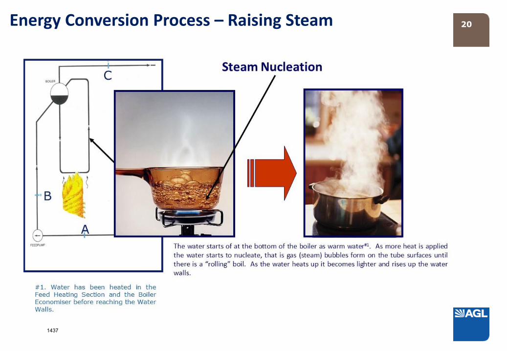
Modern coal fired power station boilers are known as water tube type boilers. That is water and/or steam passes through the tubes of the boileras opposed to fire passing through the tubes in a traditional “locomotive” type boiler or fire tube boilers. The process set out below refers tosubcritical type boilers.
The boiler consists of a furnace and convective gas pass. As the name suggests, coal combustion takes place in the furnace. The furnace consistsof a box type structure who’s walls are made from steel tubes and are referred to as water walls. Water passes through these tubes. Heat fromthe coal combustion process passes through the tube walls and heats the water within. As the water is heated, the less dense hot water rises upthrough the tubes. On taking on enough heat from the furnace, the water starts to “boil” in the tube thus producing a mixture of steam andwater.
Energy Conversion Process – Raising Steam
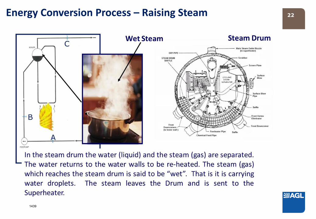
Separation of the steam from the hot water takes place in aseparator vessel at the top of the boiler called the steam drum.The hot water is returned to the bottom of the boiler to re-enterthe water walls for further heating.
The separated steam passes to the superheater which consists ofmore tubes located in and around the hot gas pass of the boiler.The majority of these tubes are arranged in platens or bundles(sometimes known as elements) which hang in the path of the hotgases passing out of the boiler furnace. The superheater platenstransfer heat energy from the hot gases to the steam within thetubes thus increasing the amount of energy in the steam. Thesteam then passes to the turbines to do work.
A second steam circuit can exist and that is the reheat circuit. Thiscircuit involves steam which has typically passed through the highpressure turbine and is returned to the boiler to add more energy.The reheat circuit is typically tube platens also in the hot gas pathof the boiler.
1432

16BOILER CONSTRUCTION
BOILER WALLS – MEMBRANE CONSTRUCTION
Energy Conversion Process – Raising Steam
BOILER FURNACE
The Walls of Boiler are made from steel Tubes in which the water / steam are contained
1433

17Energy Conversion Process – Raising Steam
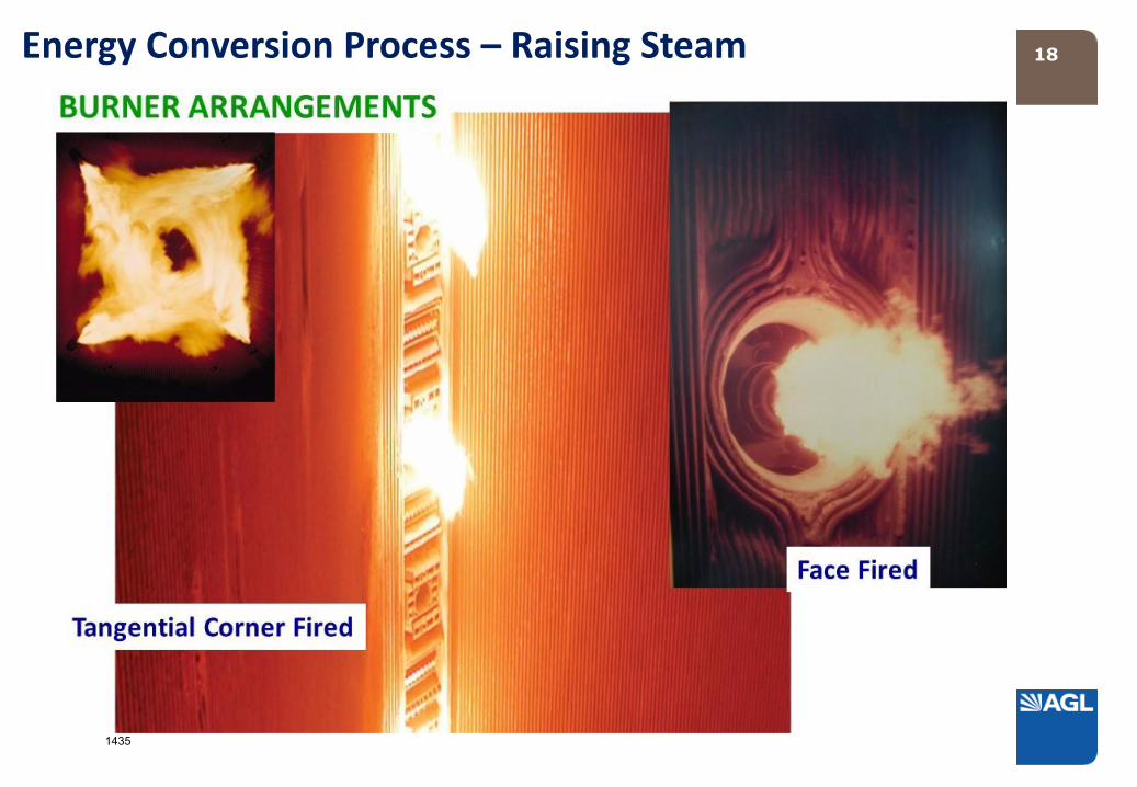
Pulverised Fuel & Primary Air
Boiler Furnance Wall
Boiler Furnance Wall
Burner
Burner
PF Combustion inside in the Boiler Furnance
1434
18Energy Conversion Process – Raising Steam
1435

19Energy Conversion Process – Raising Steam
1436
20Energy Conversion Process – Raising Steam
1437

21Energy Conversion Process – Raising Steam
1438
22Energy Conversion Process – Raising Steam
1439

23
The Superheater
Energy Conversion Process – Raising Steam
Wet Steam (gas) passes from the Steam Drum and passes throughthe Superheater where the steam is heated further drying thesteam.
The Superheater consists of arrangements oftubes called elements. Which is arranged in theBoiler to take up heat through either radiation inthe Furnace or by convection in the Gas Pass.
1440

24Energy Conversion Process – Raising Steam
Typical Black Coal
Boiler Cross - Section
1441

25GAS HANDLING (AIR & EXHAUST)Energy Conversion Process – Air / Gas Handling
Combustion requires the presence of oxygen. Oxygen is made available to the combustion process in a coal fired boiler through theintroduction of air in very large volumes. The point of introduction of the air is important to the completeness of the combustion process.Too little air results in incomplete combustion and too much air is an inefficiency.
The fire triangle illustrates the rule that in order to ignite and burn, a firerequires three elements: heat, fuel, and an oxidizing agent, usually oxygen. Thecombustion is prevented or extinguished by removing any one of them. A firenaturally occurs when the elements are combined in the right mixture. Withoutsufficient heat, combustion cannot begin, and it cannot continue. Without fuel,combustion will stop. Without sufficient Oxygen, a combustion cannot begin,and it cannot continue. The chemical reactions associated with a fire has led todevelopment of the fire tetrahedron: a triangular pyramid having four sidesincluding the bottom representing the sustaining of chemical reactions. Thatchemical reaction is called combustion and feeds a fire more heat and allows itto continue.
To aid efficiency, the air is heated prior to entering the boiler by passing itthrough a heat exchanger device known as an air-heater. The air-heatermakes use of waste heat present in the boiler exhaust gases as they leave theboiler. There are basically two types of air heaters, tubular and regenerative.
The air is also used as a transport medium for the transport of the pulverisedfuel through the mill and on into the boiler through the burners.
Many modern pulverised fuel boilers are called balanced draft as there arefans both pushing air into the boiler and other fans drawing exhaust gases out.The fans forcing air in are called forced draft fans and those drawing air out arecalled induced draft fans.
1442

26
BALANCED DRAFT
Energy Conversion Process – Air / Gas Handling
1443

27
Regenerative Air Heaters – Rotating Element: consist of a central rotating arrangement (rotor) of heat transfer plates arranged in segments.This rotor is located within a casing that is divided into two (bi-sector type), three (tri-sector type) or four (quad-sector type) sectorscontaining seals around the element. The seals allow the element to rotate through all the sectors, but keep gas leakage between sectors toa minimum while providing separate gas air and flue gas paths through each sector.
Tri-sector types are the most common in modern power generation facilities. In the tri-sector design, the largest sector (usually spanningabout half the cross-section of the casing) is connected to the boiler hot gas outlet. The hot exhaust gas flows over the central element,transferring some of its heat to the element, and is then ducted away for further treatment in dust collectors and other equipment beforebeing expelled from the flue gas stack.
The second, smaller sector, is fed with ambient air by a fan, which passes over the heated element as it rotates into the sector, and isheated before being carried to the boiler furnace for combustion. The third sector is the smallest one and it heats air which is routed intothe pulverises and used to carry the coal-air mixture to the boiler burners. Thus, the total air heated in the Air Heater provides: heating airto remove the moisture from the pulverised coal dust, carrier air for transporting the pulverised coal to the boiler burners and the primaryair for combustion.
The rotor itself is the medium of heat transfer in this system, and is usually composed of some form of steel and/or ceramic structure. Itrotates quite slowly (around 3-5 RPM) to allow optimum heat transfer first from the hot exhaust gases to the element, then as it rotates,from the element to the cooler air in the other sectors.
In this design the whole air heater casing is supported on the boiler supporting structure itself with necessary expansion joints in theducting.
The vertical rotor is supported on thrust bearings at the lower end and has an oil bath lubrication, cooled by water circulating in coils insidethe oil bath. This arrangement is for cooling the lower end of the shaft, as this end of the vertical rotor is on the hot end of the ducting. Thetop end of the rotor has a simple roller bearing to hold the shaft in a vertical position.
The rotor is built up on the vertical shaft with radial supports and cages for holding the baskets in position. Radial and circumferential sealplates are also provided to avoid leakages of gases or air between the sectors or between the duct and the casing while in rotation.
Energy Conversion Process – Air / Gas Handling
1444

28
Regenerative Air Heaters – Rotating Element cont’d: For on line cleaning of the deposits from the baskets steam jets are provided such thatthe blown out dust and ash are collected at the bottom ash hopper of the air heater. This dust hopper is connected for emptying along withthe main dust hoppers of the dust collectors.
The rotor is turned by an electric motor and gearing, and is required to be started before starting the boiler and also to be kept in rotationfor some time after the boiler is stopped, to avoid uneven expansion and contraction resulting in warping or cracking of the rotor.
The baskets are in the sector housings provided on the rotor and are renewable. The life of the baskets depend on the ash abrasiveness andcorrosiveness of the boiler outlet gases.
Regenerative Air Heaters – Stationary Element: are a type of regenerative air heater and are also installed in a casing, but the heating plateelements are stationary rather than rotating. Instead the air ducts in the air heater are rotated so as to alternatively expose sections of theheating plate elements to the up flowing cool air. There are rotating inlet air ducts at the bottom of the stationary plates similar to therotating outlet air ducts at the top of the stationary plates.
Stationary element regenerative air heaters are also known as Rothemuhle air heaters, manufactured for over 25 years by Balke-Dürr GmbHof Ratingen, Germany as well as a number of licenses around the world.
Energy Conversion Process – Air / Gas Handling
1445

29Energy Conversion Process – Gas Cleaning / Ash Handling
1446

30
The solid by-products of coal combustion in ash. Modern pulverised fuel fired boilers produce ash in two forms, bottom ash and fly ash. As the namesuggests bottom ash represents the heavier ash particles which fall to the bottom of the boiler furnace and are removed. The fly ash is the majority ofthe ash produced and consists of small and lighter particles which are carried out of the boiler in the exhaust gas stream.
The exhaust gases are destined for final release to the atmosphere and thus the vast majority of ash particles must be cleaned from the exhaust gases.There are two basic methods for the cleaning of exhaust gas streams. The first is the use of fabric filters or bag houses. In this case the exhaust gas ispassed through a porous fabric filter material which traps the ash particles and forms a cake of dust on the up stream surface of the fabric. Theparticles are routinely removed from the fabric filter by applying a pulse air blast in the opposite direction to the exhaust gas flow. The ash cake fallsinto a hopper below for removal.
Energy Conversion Process – Gas Cleaning / Ash Handling
The second method of removing fly ash from the exhaust gas streams is by theuse of electrostatic precipitation. Electrostatic precipitators use electrostaticforces to separate dust particles from exhaust gases. A number of high-voltage, direct-current discharge electrodes are placed between groundedcollecting electrodes. The contaminated gases flow through the passageformed by the discharge and collecting electrodes. The airborne particlesreceive a negative charge as they pass through the ionized field between theelectrodes. These charged particles are then attracted to a grounded orpositively charged electrode and adhere to it. The collected material on theelectrodes is removed by rapping or vibrating the collecting electrodes eithercontinuously or at a predetermined interval.
Ash from coal fired power stations also has a number of applications such as anadditive to concrete and as road stabilising material.
1447

31
Typical Fabric (Bag) Filters
Energy Conversion Process – Gas Cleaning
1448

32
Steam from the boiler is used to drive steam turbines which are themselves joined via a shaft to the generator. The turbines convert theenergy in the steam into mechanical energy to drive the generator.
Typically there are a series of turbines consisting of high pressure, intermediate pressure and low pressure. There are a number ofcombinations of turbines which have found applications. It is not uncommon on large units to find more than one low pressure turbine.
Steam turbines consists of a set of stationary blades held in the casing and a set of rotating blades mounted on the turbine shaft. Steam isdirected by the fixed blading onto the rotating blading causing the rotating blading to drive the turbine shaft. There are a number of stagesof blading in any turbine. Each successive stage of blading sees steam with slightly less energy as some energy has been given up as work inthe previous stage.
Energy Conversion Process – Steam Turbine
1449

33
Typical Power Station Turbines Arrangement
Energy Conversion Process – Steam TurbineLow Pressure Turbine Rotar
High Pressure Turbine Rotar
1450

34
280 MW HP TURBINE BLADE
Energy Conversion Process – Steam Turbine
Steam “pushes’ on the Turbine Blades causeing them to rotate the Turbine Rotor
1451

35
The Laws of Physics: For energy to be useful, it must flowAnd it wants to flow from high concentrations to lowerconcentrations.
Cooling Tower
Energy Conversion Process – Cooling Water System
26/04/08
Cooling Water System
Steam / Cooling
Water Heat Exchanger
Pump
Generator
Turbine
Boiler
Pump
COLD WATER IN
HOT WATER OUT
HEAT SINK
1452

36
The primary function of a cooling water system within a thermal power station is the cooling of the steam turbine exhausts so that inaccordance with the Second Law of Thermodynamics: work can be done by the steam passing through the turbine due to the flow ofheat from a hot to cold body (the steam).
Cooling systems usually have a secondary function, cooling auxiliary systems such as Generator Hydrogen Coolers.
Energy Conversion Process – Cooling Water System
Internal Viewof Condensor
1453

37
THE CONDENSER
Hot Cooling Water Out
Exhaust Steam
Cold Cooling Water In
Steam SupplyTurbine
Generator
Condenser
Condensate to feed water
circuitCondensate pump
Energy Conversion Process – Cooling Water System
1454

38
Liddell Power Station in NSW is cooled by water circulated through a
man-made Lake
LAKE COOLED
Energy Conversion Process – Cooling Water System
1455

39
The generator is driven by a common shaft from the turbines. The generator consists of a rotor (rotating element) and a stator (stationaryelement). The rotor is driven by the turbines. The rotor forms a rotating electro magnet. The stator consists of the windings in which acurrent is induced.
A large amount of heat can be generated in large power station generators and thus various cooling mechanism must be employed. Acommon method is to cool the rotor and stator with hydrogen gas. Hydrogen is used for its excellent heat transfer capacity. Statorwindings can be either hydrogen cooled or additionally water cooled.
Energy Conversion Process – Generators
1456

40
Frequency = Number of Cycles per Period of Time (Cycles per Second)
Alternating Current (AC)
3,000 r.p.m. = 50 Cycles per Second {50 Hertz (Hz.)}
Energy Conversion Process – Generators
1457

41Energy Conversion Process – Generators
660MWToshiba/GE
Generator Stator
The speed of the generator rotor is kept constant to maintain the frequency.The power produced by the generated (Mega Watts) is effectively changedby the strength of the rotating magnetic circuit. With increasing fieldstrength, the torque required to drive the rotor increases and thus thepower required from the turbines and boiler increases.
1458

42Energy Conversion Process – Water Systems
1459

43
Water chemistry is critical to steam generating plants.
In the steam-generating plant, water treatment is particularly critical to both operating efficiency and equipment life. The feedwatermakeup must be pure, and the recirculating boiler water and condensate must be kept scrupulously free of contaminants and dissolvedoxygen (usually). The pH must be precisely controlled; and the exposed metal surfaces in the boiler, the feedwater heaters, and theboiler feed pumps must be protected.
Boiler feedwater consists of makeup water plus condensed steam. For makeup, many plants utilise raw water that requirespretreatment with some combination of clarifiers, sand filters and mixed media filters. The resulting water then undergoes additionaltreatment through reverse osmosis (RO) membranes, demineralisers, electrodeionisers, ultrafiltration or other systems. The final lowconductivity ultra pure water provides the levels needed for optimal boiler performance.
So, boiler water treatment can fall into broad areas:
1) Makeup water preparation; and
2) Internal boiler water (including condensate) treatment.
All natural waters contain varying amounts of suspended and dissolved matter as well as dissolved gases. Feedwater must bepretreated to remove impurities to control deposition, carryover, and corrosion in the boiler system. Poor quality water gives poorquality steam. The first step in any treatment is filtration of suspended solids.
Dissolved minerals:Dissolved minerals picked up by the water consist mainly of calcium carbonate (limestone), calcium sulphate (gypsum), magnesiumcarbonate (dolomite), magnesium sulphate (epsom salts), silica (sand), sodium chloride (common salt), hydrated sodium sulphate(glauber salt), and smaller quantities of iron, manganese, fluorides, aluminium, and other substances. The nitrates and phosphatesfound in water are usually due to sewage contamination.
Energy Conversion Process – Water Systems
1460

44
Dissolved gases in water:
Water contains varying amounts of dissolved air (21% oxygen, 78% nitrogen, 1% other gases including carbon dioxide). Water can containup to 9ppm oxygen at room temperature and atmospheric pressure. As the temperature increases, the solubility of oxygen decreases,but water under pressure can hold higher amounts of dissolved oxygen. Nitrogen, being inert, has little effect on water used in boilers.Water can contain 10ppm of carbon dioxide, sometimes much more than that due to decaying vegetation and organics in soil. Hydrogensulphide and methane may be dissolved in water but this is rare. These gases can be troublesome when they are present in the feedwater.
Other impurities in water:
Natural waters contain varying levels of soil, sand, turbidity, colour, precipitated minerals, oil, industrial wastes and other suspended solidparticles. Turbidity is due to very fine organic materials and micro-organisms, as well as suspended clay and silt. Colour is due to thedecaying vegetable matter.
Corrosion:
Corrosion is basically the reversion of a metal to its ore form. Iron, for example, reverts to iron oxide as a result of corrosion. The processof corrosion is actually not so simple, it is a complex electro-mechanical reaction. Corrosion may generally be over a large metal surfacebut sometimes it results in pinpoint penetration of metal. Though basic corrosion is usually due to reaction of the metal with oxygen,other factors including stresses produce different forms of attack. Corrosion may occur in the feedwater system as a result of low pHwater and the presence of dissolved oxygen and carbon dioxide. Corrosion in the boiler itself normally occurs when boiler wateralkalinity is too low or too high or when the metal is exposed to oxygen-bearing water during either operation or idle periods. Hightemperatures and stresses tend to accelerate the corrosion. In the steam and condensate system pipeline corrosion is generally theresult of contamination with carbon dioxide and oxygen.
Deposits:
Deposits in the steam/water circuit of the boiler, turbine and feeding/ heating systems can vary from silicates to copper. In many casessludges can accumulate in the boiler and are addressed through blowing down. However, a number of contaminants can deposit on“wetted” surfaces causing problems with heat transfer and flow restrictions. Heat transfer problems are often a cause of pressure partfailures.
Energy Conversion Process – Water Systems
1461

45Energy Conversion Process – Water Systems (Generators)Due to the energy concentrations and the materials involved, large Generators require significantamounts of cooling.
A key element in the cooling process is Hydrogen gas which is a very good heat transfer medium but,then must itself be cooled. It is also common to find the Stator of the Generator has water cooledcomponents (Bars). The water used in these applications MUST be very pure to avoid blockage of verysmall and long cooling channels.
Copper corrosion in the strands of a GeneratorStator bar due to poor water chemistry
1462

46
All of the physical plant elements of a large modern thermal power station are tied together via a control system. The control systemconsists of instruments distributed through the plant that report back to a central data processing unit information related to theoperating conditions of the plant and processes. The central processing elements then analyse this information and check againstparameters that are either automatically set or set by the operator. Then any changes or adjustments to the plant are made throughthe control elements of the control system which consists of signals being sent to various devices throughout the plant that can act tochange plant or process conditions.
Energy Conversion Process – Instrumentation & Control
1463

47
Typical Power StationGenerator Transformer
Energy Conversion Process – Sending Electricity Out
1464

48
De Lorenzi, O., (ed.), 1957, Combustion Engineering – A Reference Book On Fuel Burning And Steam Generation,1st edn., Combustion Engineering, Inc., New York, USA.
Juniper, L., 2000, Thermal Coal Technology – A Manual For Australian Coal, QTHERM Program – QueenslandDepartment of Mines and Energy (Ultra-Systems Technology Pty. Ltd.,) Brisbane, Australia.
Reynolds, P. M., (Managing Editor), et al, 1991, Modern Power Station Practice, Volume ‘B’ – Boilers and AncillaryPlant, 3rd ed., British Electricity International, London, Pergamon Press, Oxford, UK.
Schumacher, G., 2010, How Electrcity Is Generated – Coal Fired Thermal Plant Coal Plants, v1a, NRG GladstoneOperating Services Pty. Ltd., Gladstone, Queensland, Australia.
Schumacher, G., 2014, Coal Pulverising Mill Types, Ed.2. v1., Community of Practice for Coal Utilisation, Brisbane,Queensland, Australia.
Singer, J. G. (ed.), 1991, Combustion Fossil Power, ABB Combustion Engineering, Inc., Windsor, Connecticut, USA.
Speight, J. G., 2005, Handbook of Coal Analysis, John Wiley & Sons, Hoboken, New Jersey, USA.
Stultz, S. C., & Kitto, J. B., (ed.), 1992, Steam – Its Generation And Use, 40th edn., Babcock & Wilcox Company,Barberton, Ohio, USA.
Bibliography
1465