Annex - VEM Group · PDF fileAnnex. Einbaumotoren Low voltage electrical machines 16/2...
29
Contents Parameters, conversions and formulae for technical units of measurement 16/2 General information to aid configuration 16/4 VEM-Product Range 16/28 16 Annex
Transcript of Annex - VEM Group · PDF fileAnnex. Einbaumotoren Low voltage electrical machines 16/2...

Contents
Parameters, conversions and formulae for technical units of measurement 16/2
General information to aid configuration 16/4
VEM-Product Range 16/28
16
Annex

EinbaumotorenLo
w v
olta
ge e
lect
rical
mac
hine
s
16/2
Parameters, conversions and formulae for technical units of measurementin SI units of measurement (Systeme Internationale d’Unitée)
Power
1 kW = 1.36 h.p. = 102 kpm/s = 1,000 Nm/s 1 h.p. = 0.736 kW = 75 kpm/s = 736 Nm/s
Work1 kWh = 3.6 x 10⁶ J = 3.6 x 10⁶ Nm = 0.367 x 10⁶ kpm1 Ws = 1 J = 1 Nm = 0.102 kpm
Force1 N = 0.102 kp 1 kp = 9.81 N
Torque1 Nm = 0.102 kpm = 1 Ws 1 kpm = 9.81 Nm = 9.81 Ws
Pressure1 Pa = 1 N/m2
1 bar = 105 Pa1 mm water gauge = 9.81 Pa
Temperature/temperature differences1 deg = 1 K = 1 °C
Moment of inertia1 kgm2 = 1 Ws3 = 1 Nms2 = 0.102 kpms2
Characteristic drive parameters
P1 … power input [kW]P2 … power output [kW]PB … rated power [kW]P … effective power [kW]S … apparent power [kVA]Q … reactive power [kvar]U … voltage [V]UU … lower voltage limit [V]UB … rated voltage [V]UO … upper voltage limit [V]IB … rated [nominal] current [A]fB … rated frequencycosϕ … power factor [-]cosϕB … rated power factor [-]η …. efficiency [%]ηB…. rated efficiency [%]nS … synchronous speed [rpm]nB … rated [nominal] speed [rpm]MB … rated [nominal] torque [Nm]MA … starting torque [Nm]MS … pull-up torque [Nm]MK … pull-out torque [Nm]IA … starting current [A]sB … rated slip [%]J … motor moment of inertia [kgm2]
Equivalent circuit data
R1w … stator winding equivalent resistance at operating temperature in ohms [at 120 °C winding temperature]
R2w’ … rotor winding equivalent resistance at operating temperature, referred to stator side, in ohms [at 120 °C winding temperature]
RFe … ohmic equivalent resistance [also iron equivalent resistance]
X1s … stator winding leakage reactance in ohmsX2s … rotor winding leakage reactance in ohms, referred to stator sideX1h … stator winding main reactance
Specific quantities MA/MB … relative starting torque [-] MS/MB … relative pull-up torque [-] MK/MB … relative pull-out torque [-] IA/IB … relative starting current [-]
Drive engineering formulae
Power input
Power outputP2 = P1 x η/100 [kW]
Power lossPV = P1 – P2 [KW]
Effective power
Apparent power
Reactive power
Current consumption
Rated slip
Rated torque
BB
or
or

Low
vol
tage
ele
ctric
al m
achi
nes
16
16/3
Inertia factor
Jmot … moment of inertia of motor [kgm2]Jfremd … moment of inertia of machine [kgm2]
Jges = Jfremd + Jmot
Starting time
Jges = total moment of inertia to be accelerated in kgm²nB = rated speed in rpmMbm = moment of acceleration in Nm
Formulae from acoustics
Sound pressure level
Reference sound pressure
Sound power level
Reference sound power
Measuring-surface level
Reference surface
Lp … sound pressure level [dB]P … sound pressure [Pa]P0 … reference sound pressure [Pa]Lw … sound power level [dB]P … sound power [W]P0 … reference sound power [W]Ls … measuring-surface level [dB]S … measuring surface [m2]So … reference surface [m2]
p0 = 2 x 10⁻⁵ [Pa]
P0 = 10-12 [W]
S0 = 1 m2
Power demand of selected machines
Lifting movement
Rotating movement
Fan drive
Pump drive
P … power [kW]F … force [N]v … velocity [m/s]η … efficiencyM… torque [Nm]n … speed [rpm]V … delivery rate [m3/s]p … total counterpressure to be overcome [N/m2]
Torques
Conversion of torques for step-down and step-up gearing
n1 … motor speed [rpm] M1 … motor torque [Nm] n2 … working speed [rpm] M2 … torque at n2 [Nm]
Moment of inertia
related to rotative moment
J … moment of inertia [kgm2]GD2 … rotative moment [kpm2]
Conversion of moments of inertia to another speed for step-down or step-up gearing
n1 … motor speedJ1 … moment of inertia at n1n2 … working speedJ2 … moment of inertia at n2
M2 =

EinbaumotorenLo
w v
olta
ge e
lect
rical
mac
hine
s
16/4
1. Torque behaviour and starting current
Fig. 1 shows the characteristic behaviour of torque/current in asynchronous machines for all areas of practical interest.
Figure 1: Characteristic behaviour of torque/current in three-phase asynchronous motors
M = TorqueI1 = Stator currentn/nSyn = Ratio speed/synchronous speed s = Slip
The torque characteristics of squirrel-cage and slip-ring motors differ significantly in the range 1.2 < n/ns < 0.8 due to the specific current displacement effect attributable to the cage design of squirrel-cage motors. By contrast, the characteristic current behaviour of the two machine types is practically identical.
IA = Starting current (also known as short-circuit current). Max. current drawn by a motor at standstill when supplied with rated voltage/rated frequency in all possible rotor positions after transient reactions have passed.
MA = Starting torque (also known as stalled torque). Smallest torque occurring on the shaft end when a motor is supplied with rated voltage/rated fre-quency in all possible rotor positions after transient reactions have passed.
MS = Pull-up torque (also known as ramp-up torque). Smallest torque occurring on the shaft end of a motor supplied with rated voltage/rated frequen-cy over the range between standstill and sweep speed when speed changes slowly.
nS = Pull-up speed related to the pull-up torqueMK = Pull-out torque First torque maximum on the shaft end of a
machine supplied with rated voltage/rated frequency when speed is slowly reduced starting from synchronous speed.
MB = Rated torquenB = Rated speednSyn = Synchronous speed
Figure 2: Characteristic behaviour of torque/current in a squirrel-cage motor
reverse current-brake area motor area generator area
Msquirrel-cage rotor
M squirrel-cage rotor
Mslip-ring rotor
Mslip-ring rotor
These curves identify characteristic parameters for the motor range of three-phase motors. These parameters are explained in Fig. 2 using the basic characteristic of a squirrel-cage motor.
General information to aid configuration

Low
vol
tage
ele
ctric
al m
achi
nes
16
16/5
It is standard practice to relate torque and current quantities to the design data of a motor:
Relative starting current iA = IAIB
Relative starting torque mA = MA
MB
Relative pull-up torque mS = MS
MB
Relative pull-out torque mK = MK
MB
Minimum values for the relative pull-out, pull-up and starting torques for three-phase motors are specified in IEC/EN 60034-12.
The actual characteristics achieved by modern standard motors generally far exceed these minimum requirements. Current and torque characteristic data for squirrel-cage motors are given in the technical data, making it possible to predetermine the speed-torque characteristic with suf-ficient accuracy, for example to judge the starting behav-iour of squirrel-cage motors.
2. Operating characteristics
This is understood to designate the behaviour of essential operating values of a motor over the stable working range between no-load running and outputs in the area of the rated output. These values are normally plotted as a function of output (Fig. 3).
Operating characteristics are an important aid for the eva-luation of drives, particularly with regard to partial load and overload behaviour. Partial load values for the power factor cosϕ and efficiency η of standard motors can be found in the tables of motor selection data. All other operating values, in particular power output and thus actual load, are easy to determine by measuring the absorbed power or stator current. Operating characteristics for standard motors can be found in our electronic catalogue VEMe-KAT; they can also be requested directly from the motor manufacturer.
Essential operating values such as efficiency η and power factor cosϕ have been defined in the course of motor de-sign such that an optimum is achieved at rated output P2B.
While efficiency varies only slightly over a comparatively wide range, a major drop in the power factor must be expected in the partial load range. Figs. 4 and 5 permit corresponding estimations for most cases.
Rated values for operating data can be found in the cor-responding technical documentation or else on the rating plate of the motor concerned. Where the efficiency of a motor is not specified on the rating plate, it can be calcu-lated from the standard data as follows:
ηB = P2B
√3 · U1B · I1B · cosϕB
Most operating characteristics specify the slip s, enabling the corresponding speed to be determined as follows:
1
· 100 %
n = nSyn (1 – s)nSyn = synchronous speed
Figure 3: Operating characteristics of an asynchronous motor
Figure 4: Efficiency in the partial load and overload range
0.5
0.95
0.9
0.85
0.75 1 1.25
Figure 5: Power factors in the partial load and overload range
0.5
1.05
1
0.95
0.9
0.85
0.8
0.75
0.7
0.75 1 1.25
P2B P2
P1
P1; I1; s;

EinbaumotorenLo
w v
olta
ge e
lect
rical
mac
hine
sGeneral information to aid configuration
16/6
3. Pole-changing motors
The mechanical construction of a pole-changing motor corresponds to that of a squirrel-cage motor in its basic version, which means that mounting and assembly dimen-sions are identical, with the exception of a few versions with three or four speeds, where a larger terminal box is required. In such cases, the dimensions HD (p) and O (r) deviate from the dimensioned drawings for the basic versions.
Pole changing is achieved by appropriate configuration of the stator windings. For motors with two speeds at a ratio of 1:2, a Dahlander winding is preferred. Where other ratios between the two speeds are required, the motor possesses two separate windings. Two windings, one or both of which are designed with Dahlander connection, are needed where a motor has three or more speeds.
Pole-changing motors are designed for direct starting (lowest speed), and higher speeds should normally be reached by going through the lower stages first. For switch-ing back (braking), see the notes given in section 10.
Connecting terminals are designated in accordance with IEC/EN 60034-8.
Examples of terminal connection plans are shown in Fig. 6.
Figure 6: Terminal connection plans (examples)
On an ever growing scale, squirrel-cage motors are fed through a frequency converter for speed control and/or variable-speed operation. Through appropriate programm-ing of the frequency converter, the drive can be confi- gured and adapted optimally for any required speed.
The operating point of a pump or fan drive, for example, can be adjusted to the required flow rate. Compared to volume flow control via regulators or pole-changing motors, this achieves considerable energy savings.
With regard to the individual numbers of poles and speeds, the notes given in section 1 apply equally to pole changing motors, with the exception of the specified minimum values for relative pull-out, pull-up and starting torque, which are expressly exempted from IEC/EN 60034-12.Pole-changing squirrel-cage motors are suitable for use as machine tool drives, for example. They are able to replace multiple-speed gearboxes or else considerably widen their speed control ranges.
In many drives, they are also a suitable substitute for slip-ring motors, the advantage being better efficiency at lower speeds. Pole-changing motors combine the basic robust-ness of squirrel-cage motors with stepped speed control. That is not least the reason why they are used in many special drive applications:– Lifting gear motors (exact positioning to floor height
at low speed, travel at high speed)– Slide rest adjustment (approach at low speed,
retraction at high speed)– Planers (working pass at low speed, reversing at high speed) – Pumps, fans, textile machines and similar drives
KP 0001 Standard motor in D/Y connection
KP 1000 One set of thermal winding protection
KP 0003 Pole changing motor, Dahlander connection
KP 0006 Pole changing motor with 2 windings
D-connection
winding 1
low
vol
tage
high
vol
tage
D-connection
Y-connection
built-in sensors TPM
high
spe
ed
high
spe
ed
low
spe
ed
low
spe
ed
winding 2Y-connection

Low
vol
tage
ele
ctric
al m
achi
nes
16
16/7
4. Multi-voltage motors
Multi-voltage motors can be operated with the same rated output on mains supplies with different voltages. Their mechanical construction corresponds to that of mo-tors in the basic version, which means that mounting and assembly dimensions are identical, with the exception of a few motor sizes which use larger terminal boxes because they require terminal bases with 9 or 12 terminal studs. In these cases, the dimensions HD (p) and O (r) deviate from the dimensioned drawings of the basic versions.
Voltage switching is achieved by appropriate configuration of the stator windings. The windings are manufactured in two groups, which can then be connected in series or parallel as required. The following voltage combinations are typical:
– 400/690 V in winding configuration D/Y This is identical to the basic version.
It is suitable for: 400 V for direct or Y/D starting 690 V for direct starting only There is no reduction in output.– 230/400 V in winding configuration D/Y
similar to 400/690 V in winding configuration D/Y– 230/460 V in winding configuration DD/D
similar to 230/400 V in winding configuration DD/D , but without reduced output.
For other voltages, it is necessary to consult the manufacturer.
The use of multi-voltage electric motors is proven above all in mobile applications (e.g. motors for marine use), where operation requires connection to mains supplies with different voltages.
5. Use of standard three-phase asynchronous motors as single-phase motors
Any three-phase squirrel-cage motor can be operated on a single-phase mains if the required phase shift is produced by an operating capacitor (“Steinmetz circuit”). The circuit is shown in Fig. 8.
Figure 7: Terminal connection plans for 2 voltages and Y-D starting
Figure 8: Connection of a 230/400 V three-phase motor as a single-phase motor with operating capacitor
Capacitor size is important for smooth operation. To achie-ve the required starting torque, a large capacity is needed
for the short-circuit current phase shift. For a phase shift matching the rated operation of the motor, the chosen capacity for the capacitor should not be too large. Starting behaviour is improved if a starting capacitor (which is then switched off after startup) is connected in parallel to the operating capacitor. Selecting a capacitor size from the table below gives the following operating behaviour:– Output max. 70 % of three-phase output– Starting torque approx. 20–30 % of the rated torque
in single-phase operation
Due to low initial torques and unfavourable main charac-teristics, these motors can only be used with reduced starting loads, e.g. for fan drives. Motor operating capaci-tors should normally be designed for continuous operating voltages of 1.2 to 1.5 times the mains voltage, i.e. at least 276 V for a 230 V mains. For other mains voltages, the capacitor size should be calculated as the inverse ratio of the square of the mains voltage.For technical and economic reasons, the use of a three-phase motor with continuous operating capacitor as a single-phase motor is only meaningful up to a single phase output of around 1 to 2 kW.
Output P2 for single-phase operation in kW
Capacity C μFat 3,000 rpm at 1,500 and 1,000 rpm
0.2 16 – 20 20 – 300.4 25 – 40 30 – 400.6 40 – 50 50 – 600.8 60 – 80 70 – 901.0 80 – 100 90 – 1001.2 100 – 120 120 – 1401.4 120 – 140 140 – 160
broken line for capacitor with reversedirection of rotation
starting connectionlow voltage
YY-connection
operational connectionlow voltage
D D-connection
starting connectionhigh voltage
Y-connection
operational connectionhigh voltage
D-connection
motor terminal plate
capacitor

EinbaumotorenLo
w v
olta
ge e
lect
rical
mac
hine
sGeneral information to aid configuration
16/8
6. Selecting a motor
Drive design and the right choice of a motor are instrumen-tal in determining the cost-benefit ratio, avoid setbacks in operation and play a decisive role for economic efficiency. When selecting a motor, all contributing factors such as power demand, operating mode, speed, mains/starting/braking/control conditions, bearing/shaft loads and ambient conditions must be taken into account.
The right choice will often be the basic version. It is there-fore assumed for the different operating modes that there is a return to duty type S1 (continuous duty) such that motors are used in the basic mode.
7. Reaction torque, power consumption, moment of inertia
The mechanical power required by a driven machine for continuous duty or at equilibrium in any other operating mode is determined as follows:
where Mg = reaction torque of the driven machine in Nm nA = speed of the driven machine in rpm
For directly coupled drives, this is also the power con-sumption (PA = P2) of the motor. If a torque converter (gear unit, belt drive) is placed between the machine and drive motor, the power consumption of the motor is calculated with
where ηG = torque converter efficiency
PA = Mg · nA 9550
in kW
P2 = PA
ηG =
Mg · nA 9550 · ηG
in kW
The aforementioned equations apply only to purely rotati-onal motions. The reaction torque for machines with linear motions must be determined as follows:
Mg = 9,56 · in Nm
where FA = load in N v = speed in m/s nM = motor speed in rpm
The reaction torque and power consumption of a machine are generally a function of the speed. To improve under-standing between manufacturers and the users of motors, examples of characteristic reaction torque behaviour are specified and described below (Fig. 9).
– Torque practically constant over speed (a) This is the case, for example, for lifting gear, winches, conveyor belts, compressors, when conveying against constant pressures, etc.
– Linear rise of torque with speed (b) for example for the drives of generators working against constant loads, frequency converters, etc.– Torque rises at a specific power (e. g. parabolic) of speed (c) This behaviour is found in the drives of fans, rotary pumps, centrifuges, etc.
Figure 9: Reaction torque characteristics of machines
Other forms of torque behaviour are possible in practice, but these are of lesser importance or else can be traced back to the characteristics explained. Please note that in-creased friction or adhesion torques may occur at speeds close to zero; such torques are known as breakaway torques and may reach considerable levels (e. g. starting of a piston compressor at low temperatures). These break- away torques should be known as accurately as possible and must be taken into consideration when assessing starting behaviour.
The total moment of inertia of a drive can be described with
where JM = motor moment of inertia (to be taken from the technical data of the motor series in question) JF = motor-speed-related sum of moments of
inertia of the driven components
Once the moment of inertia of a driven machine has been determined for the speed of the machine using known procedures, the following conversion yields the motor shaft speed:
where JA = moment of inertia of the driven machine at nA
FA · v nM · ηG
MgB = reaction torque at nB
nominal point
J = JM + JF

Low
vol
tage
ele
ctric
al m
achi
nes
16
16/9
8.1. Motor output for continuous duty (duty type S1)
Here, selection is simple because load either does not change or at most fluctuates. The technical data enable selection of a motor with an output equal to or greater than the constant or effective load. The following thus applies for constant load
The individual load portions should be sufficiently small, i.e. tn< τ1 or tn « τ2, where τ1 and τ2 stand for the thermal time constants of the motor. If tn is greater, select the motor according to the highest occurring load portion.
When selecting motors for continuous duty, it is important to ensure that– the rated output of the selected motors lies as closely
as possible above the power consumption, as severely underloaded motors yield poor operating values. On the other hand, there is very little room for overloading due to the high utilisation of modern motors
– attention is given to the starting frequency of the drive. If several start-ups are required per hour, for example, then consultation with the manufacturer may be appropriate, depending on the severity of starting conditions. Design work should follow the rules for switching modes as explained below, as this is no longer S1 operation.
where Mg = reaction torque of the driven machine in Nm P2B = motor rated output (list output) in kW PA = power consumption of a driven machine in kW nA = machine speed in rpm If loads fluctuate, the following criteria are used for selection:
where Mgeff = effective reaction torque in Nm PAm = mean power consumption of the
machine in kW
starting time
time of operation under load
time of braking
resting time
Figure 10: Example of a working cycle
Figure 11: Reaction torque in continuous duty S1
8. Motor selection for different duty types
This section deals with motor selection on the basis of elec-tric/thermal loads. The decisive parameter when determining motor output is not simply the load at equilibrium. Allowance must also be made for dynamic processes, the final criterion being compliance with a permissible winding temperature rise.
Prerequisite for assignment to a duty type is a load dia-gram or working cycle showing the torques and outputs to be delivered by the drive, referred to the desired motor speed, over a certain course of time.

EinbaumotorenLo
w v
olta
ge e
lect
rical
mac
hine
sGeneral information to aid configuration
16/10
8.2. Motor output in short-time duty (duty type S2)
First use power consumption P2 for the load phase in S1, as determined from the equations above, to select a motor, then check the corresponding conditions for duty type S2.The following applies: Operating time tP < 3 · τ2Interval time tR > 3 * τ2St
where τ2 = thermal time constant of the motor in operation
τ2St = thermal time constant of the motor at standstill (cooling)
In general, the conditions for short-time duty S2 are met by operating periods up to around 60 minutes with correspon-dingly longer interval times. Preferred values for the ope-rating periods are given in the next table. The permissible output PS2 for the selected motor in duty type S2 is determi-ned as follows:
where q = loss factor P2B = motor rated output in S1 according to
the technical data K1/K2 = ratio of no-load to load losses for rated
operation of the motor Θ2/Θ = ratio of overtemperature referring to τ2 to total overtemperaturer t2S = load time in S2
An appropriate motor has been chosen if PS2 ≥ PA, where PA represents the actual power consumption. If necessary, repeat the calculation for neighbouring motor sizes.
Output in short-time duty S2 is greater than motor rated output P2B. As a further boundary condition, therefore, consideration must be given to the relative pull-out torque. In accordance with IEC/EN 60034-1, the following applies:
where MK = pull-out torque of the selected motor MBS2 = rated torque of the motor at PS2
If this requirement is not met, a larger motor must be selected, regardless of the thermal utilisation.
Symbol Design dataType Preferred value
S1 Operating time continuous S2 Operating time 0.5; 1; 3; 5; 10; 30; 60; 90 min S3 S6 Period of one cycle 10 min S4 S5 S7 S8 Switching frequency 60, 90, 120 240, 600 c/h S3 S4 S5 S6 Relative cyclic doration factor c.d.f. 15 %; 25 %; 40 %, 60 % S4 S5 S7 S8 Moment of inertia factor Fl 1.2; 1.6; 2; 2.5; 4
8.3. Motor output in intermittent pericodic duty (duty types S3, S4, S5, S7)
Knowing that the load diagrams (working cycles) for tran-sient processes may be incomplete, it is advisable to start with a rough motor selection. To this end, the aforemen-tioned effective torque method can be used.
Figure 12: Simplified reaction torque behaviour in intermittent/switching mode

Low
vol
tage
ele
ctric
al m
achi
nes
16
16/11
Trapezoidal and triangular sections of the working cycle can be converted to a constant torque during the load phase as follows:
Figure 13: Trapezoidal and triangular reaction torquesThe approximate output is then determined with
in kW
Taking into account frequent transient processes, it may already be necessary to select a larger motor.Now, the permissible switching frequency for the selected motor can be calculated under the prevailing conditions:
FI = (JM + JF) / JM
where Zzul = permissible switching frequency Fl = moment of inertia factor fB = load factor fS = switching factor for the type of connection Z0 = no-load switching frequency in c/h
The load factor fB allows for the cyclic doration factor (c.d.f.) of the drive and the loss factor fV of the selected motor. It is defined as
The switching factor fS makes particular allowance for the type of braking used.
for switching mode with me- chanical braking (e.g. S4)
for switching mode with counter-current braking or reversing operation (e.g. S5, S7) for switching mode with DC braking
If the reaction torque during starting and/or ramp-up is less than during operation at rated speed, proceed as follows:– Calculate the switching factor fS with the mean relative
reaction torque during ramp-up.– Determine the load factor fB with the relative reaction
torque occurring at rated speed.
In switching modes with mechanical and DC braking, Z0A is used for Z0; in switching modes with counter- current braking and reversal, Z0R is used.
mg = relative resistance (load) moment referred to the rated torque of the motor
c.d.f. = relative on period in % fV = loss factor mA = mean relative starting torque mR = mean relative reversing torque mB = mean relative DC braking torque
To complete the load diagram and for accurate calculation of the relative on period ED, determine the times for transition processes as follows: Starting time
Reversing time
Braking time
where = normal motor starting time in seconds
JM = moment of inertia of the motor in Nm² nB = rated speed in rpm MB = rated torque in Nm
The magnitude of mB depends on the braking circuit used and the level of the exciting current, and cannot be speci-fied as a general value (see also section 10).
Finally, it must be checked that sufficient torque overload capacity is available.
The following applies
where MK = pull-out torque of the selected motor Mg max = max. reaction torque in the working cycle
Mg max
c.d.f. c.d.f.

EinbaumotorenLo
w v
olta
ge e
lect
rical
mac
hine
sGeneral information to aid configuration
16/12
Particularly in intermittent duty S3, the effective torque pro-cedure is sufficient to determine the required motor output. As per definition, switching operations need not be taken into consideration here.
where tP = load time tR = interval time The following then applies for motor selection: in kW
Figure 14: Working cycle in duty type S3
8.4. Motor output in continuous-operation periodic duty (duty type S6)
No general rules can be given regarding selection of a mo-tor for this mode, as the motor size is essentially dependent on the high thermal loads of the given transient processes. It is thus necessary to contact the manufacturer, specifying the following data:
where Mg = reaction torque (load) MB = motor rated torque
tP = load time tV = no-load time f0 = ratio of no-load losses to total losses at rated
torque (generally assumed to be 0.4 to 0.5)
An appropriate selection is determined with
in kW.
Checking of the torque overload capacity is performed as described in section 8.3.
8.5. Motor output in continuous-operation periodic duty with realated load/speed changes (duty type S8)
No general rules can be given regarding selection of a mo-tor for this mode, as the motor size is essentially dependent on the high thermal loads of the given transient processes. It is thus necessary to contact the manufacturer, specifying the following data:– driven machine– full working cycle (reaction torques and operating times
at the specific motor speeds)– moment of inertia of the driven machine, including
transmission elements, with specification of the reference speed
– on period per working cycle and planned switching frequency
– possible braking processes at the end of the working cycle; type of braking, braking torque
Figure 15: Working cycle in duty type S8
8.6. Operation with non-periodic load/speed changes (duty type S9) and discrete constant loads and speeds (S10)
For this mode of operation, select a constant-load motor to suit mode S1, making allowance for the frequent overloads which arise with this duty type.

Low
vol
tage
ele
ctric
al m
achi
nes
16
16/13
9. Squirrel-cage motor starting
Direct startingIn this case, the motor is conneced to the mains directly in accordance with its rated voltage. This is the simplest and most reliable type of starting for squirrel-cage motors and should be preferred. The full capacity of the motor is used for ramp-up, and the thermal load is normally kept to a minimum. Direct starting is in fact a must when starting against constant torques or reaction torques which rise steeply with increasing speed, and when accelerating large centrifugal masses (heavy load starting).
With direct starting, the mains must of course handle the full starting current of the motor, which can generally reach 4 to 8 times the motor rated current, depending on the size of the motor and the number of poles. Given today‘s stable mains, however, it can be assumed that this convenient type of starting can be used almost universally.
The paragraphs below describe a number of procedures for mains and drive conditions which do not allow direct starting.
Star-delta startingY/D starting is suitable only for motors whose operational winding is connected in D, with all 6 winding ends running out to the terminal board (e.g. 230 D, 400 D, 500 D). When starting, the winding is first connected to the mains in star configuration, causing the starting current and starting torque to drop to about 30% of their rated values. After ramp-up to a speed close to the rated speed, the winding is switched over to the operational D connection. When using Y/D starting, it is imperative to observe the following:– Since the starting torque has been reduced to about
30 % (applicable to the entire torque behaviour of the motor), it is only permissible to start without load or with a correspondingly low reaction torque, so that suffici-ent acceleration torque remains available for ramp-up. At each point of the ramp-up curve, the motor torque should be about double the reaction torque applicable at the time, so as to obtain reasonable starting times and to avoid impermissible heating of the motor winding.
– If in doubt, the torque-speed characteristics of a motor can be requested from the manufacturer.
The switchover from Y to D must not be triggered before the motor has reached a speed close to rated speed. If switchover is too early, this negates the effect of starting current reduction.
On the other hand, the Y stage should not be prolonged unnecessarily, as this may lead to impermissible heating of the motor windings. The ideal switchover point can be derived after calculation of the starting time (described below), either by testing or by current measurement (for manual switching).
Y/D starting can be realised either with manual switches or contactor control. Corresponding circuit diagrams can be found in the technical literature.
Soft startersThe fundamental mode of the motor terminal voltage is controlled via three-phase AC choppers, such that the starting current is reduced. In this way, adjustment to the load characteristic is possible to a certain extent. As the torque is reduced during starting, the notes given for Y-D starting also apply for soft starting. Here, too, it is impera-tive to check the starting behaviour. Torque data for stan-dard motors can be found in the technical data and/or the electronic catalogue VEMeKAT. The related characteristics can also be called up via the electronic catalogue. For special designs, the corresponding data can be requested from the manufacturer.
Starting with frequency converterDuring ramp-up in this arrangement, the drive can be accelerated proportionally to the frequency up to rated speed by way of an optimised U/f assignment. During ramp-up with rated current, the rated torque is available over the entire speed range; higher values are possible, depending on the frequency converter used and its individual programming.
advisableinexpedient
Y
wrong correct
Figure 16: (Un)suitable Y/D starting at different reaction torques
Figure 17: Correct choice of switchover point for Y/D connection

EinbaumotorenLo
w v
olta
ge e
lect
rical
mac
hine
sGeneral information to aid configuration
16/14
Starting time calculationFor many drives, starting time can be determined by way of a mean acceleration torque derived from the torque beha-viour of the motor and the reaction torque. The approxima-te starting time calculated on this basis is
in [s]
where Jges = total moment of inertia to be accelerated in kgm²
nB = rated speed in rpm Mbm = mean acceleration torque in Nm
The starting time is proportional to the total moment of inertia and inversely proportional to the acceleration torque. In this connection, the total moment of inertia Jges for the drive results from the moment of inertia of the motor and the external moment of inertia related to the drive shaft. Mean motor and reaction torques can be derived using suitable procedures for the determination of the arithmetic mean.
For many practical applications, the mean acceleration torque can be determined with sufficient accuracy as follows:
In certain cases, e. g. special reaction torque behaviours and low acceleration torque, however, this method for starting time calculation is no longer adequate. Starting time should then be determined in steps.
The starting time is calculated with
DtD1 = starting time in section Dni in secsDni = speed section in rpmMbmi = mean acceleration torque in section Dni in Nm
Figure 18: Simplified determination of starting time
mit
Figure 19: Accurate determination of starting time
The torque behaviour of a squirrel-cage motor can be derived with sufficient accuracy from the values for MA, MS and MK given in the technical data. If necessary, consult the manufacturer for further information.
10. Braking
In certain drive applications, it is not permissible to leave the motor or motor-machine drive unit to handle decelera-tion and stopping itself. For safety reasons, it is necessary to be able to stop a drive quickly. A drive system can be brought to standstill in a number of ways:– free coasting to stop– mechanical braking– electric braking– combination of several braking methods
(e.g. counter-current braking in connection with a mechanical brake)
Each of these methods has its advantages and disadvan-tages, and it is thus not possible to give a general recom-mendation. When designing a drive, the appropriate type of brake should be chosen according to the prevailing operating conditions.
The same technical correlations apply to all braking types, namely that braking time is inversely proportional to the resulting braking torque. The braking time can be calculated with
in secs
where Jges = total moment of inertia in Nm² nB = rated speed in rpm MBrRes = mean resulting braking torque in Nm

Low
vol
tage
ele
ctric
al m
achi
nes
16
16/15
10.1. Free coasting and mechanical braking
The braking torque for these methods stems from the mean reaction torque of the machine, the mechanical losses of the motor, and the mechanical brake. Neither
of these two methods affects motor design, as the arising losses place no thermal loads on the motor.
10.2. Electric braking
With electric braking, the braking torque applied acts in the same direction as the reaction torque of the machine. The resulting braking torque is thus calculated with:
MBrRes = MBRM + Mg
where MBrm = mean acceleration torque
To be able to design a system for electric braking, the following must be known:– max. occurring load torque– moment of inertia to be decelerated– braking time– speed, switching frequency, voltage, frequency
Electric braking functions without wear or special mainte-nance. No specific brake is needed, but the switching is more complex. When designing the system, it must be noted that the motor is additionally subject to thermal load.
Counter-current brakingThis form of braking can be used for both squirrel-cage and slip-ring motors. It is realised relatively simply by swapping two of the three three-phase connections. While the centrifugal masses of the drive continue to act in the original direction, the torque already becomes effective in the opposite direction. When the speed reaches zero, the motor must be switched off electrically to avoid a renewed ramp-up in the opposite direction (e.g. by way of a speed monitor). The braking characteristics are dependent on the rotor design.
– For squirrel-cage motors the braking characteristics are dependent above all on the shape of the rotor slot. The assessments found in the technical literature thus range from “modest” to “very powerful” braking action. In practice, testing is advisable.
– For slip-ring motors the braking characteristics are influenced by the incor-poration of additional resistors. Starting and control re-sistors can be used. The braking effect is greatest where the resistances are changed during braking.
Regarding the thermal loads placed on the motor, it must be noted that the additional warming is around 2 to 3 times that occurring during starting, particularly for squirrel-cage motors, whereas slip-ring motors produce most of the heat externally in the additional resistor. If braking occurs in conjunction with duty type S5, observe the notes given in section 8.3. The duration of occasional counter-current braking should not exceed 10 secs.
DC brakingFor this type of braking, the stator of the motor is discon-nected from the three-phase mains and subsequently supplied with a direct current after a short interval. The corresponding switching possibilities are shown in Fig. 21. The braking action can be modified by varying the value of the current. The recommended value for the DC braking current is 2 to 2.5 times the motor rated current.
The necessary excitation voltage is calculated with:
UG = IG · Rges · 1,3
where IG = excitation current (DC) Rges = total resistance, depending on the braking
circuit (Fig. 21) RPh = phase resistance (Fig. 21) The braking characteristic can be derived point by point from the motor characteristics M = f(n) and I1 = f(n).
The braking torque is calculated with:
where M = motor torque K = braking circuit factor (Fig. 21) I1 = motor current
Figure 20: Counter-current braking characteristics

EinbaumotorenLo
w v
olta
ge e
lect
rical
mac
hine
sGeneral information to aid configuration
16/16
PB1PB1
nSyn1
nSyn2
PB2
Factor K 0.861 0.707 0.944 0.472 0.408
Figure 21: Winding circuits for DC braking
The braking action is gentler than in counter-current braking, there are no shocks acting on the gear unit and/or coupling, and there is no subsequent starting in the opposite direction. Additional mechanical braking may be required towards the end of the braking process. Whether braking is better with DC or counter-current braking can only be decided for an individual case. It is without doubt, however, that DC braking offers a thermal advantage, because the resulting losses are approximately the same as for starting. In case of DC braking in duty type S5, the notes given in section 8.3 must be observed for design.
Supersynchronous brakingThree-phase asynchronous motors operate in the super-synchronous range if– a passing load accelerates the motor beyond its
synchronous speed– the mains frequency is suddenly reduced, or– a pole-changing motor is switched from a higher to
a lower speed.
Transition to the generator range causes a braking effect above the synchronous speed, though there is no braking to standstill. Fig. 23 shows the braking characteristics for a two-speed pole-changing motor. If the lower speed is already quite low, absolute standstill can be achieved with subsequent mechanical braking. For supersynchronous braking, it is advantageous that the generator braking torques are greater than the torques in motor operation. Further influ-ence is possible by way of an additional rotor resistance or changes in the stator winding circuit.When a pole-changing motor is switched back from a higher to a lower speed, the resulting braking torques may far exceed the rated torque for a short period. It may be possible to reduce this braking torque by switching back via the “0” stage, if necessary with a delay.
Squirrel-cage motor
Figure 22: Characteristics for DC braking of a squirrel-cage motor
Figure 23: Supersynchronous braking
Low
vol
tage
ele
ctric
al m
achi
nes
16
16/17
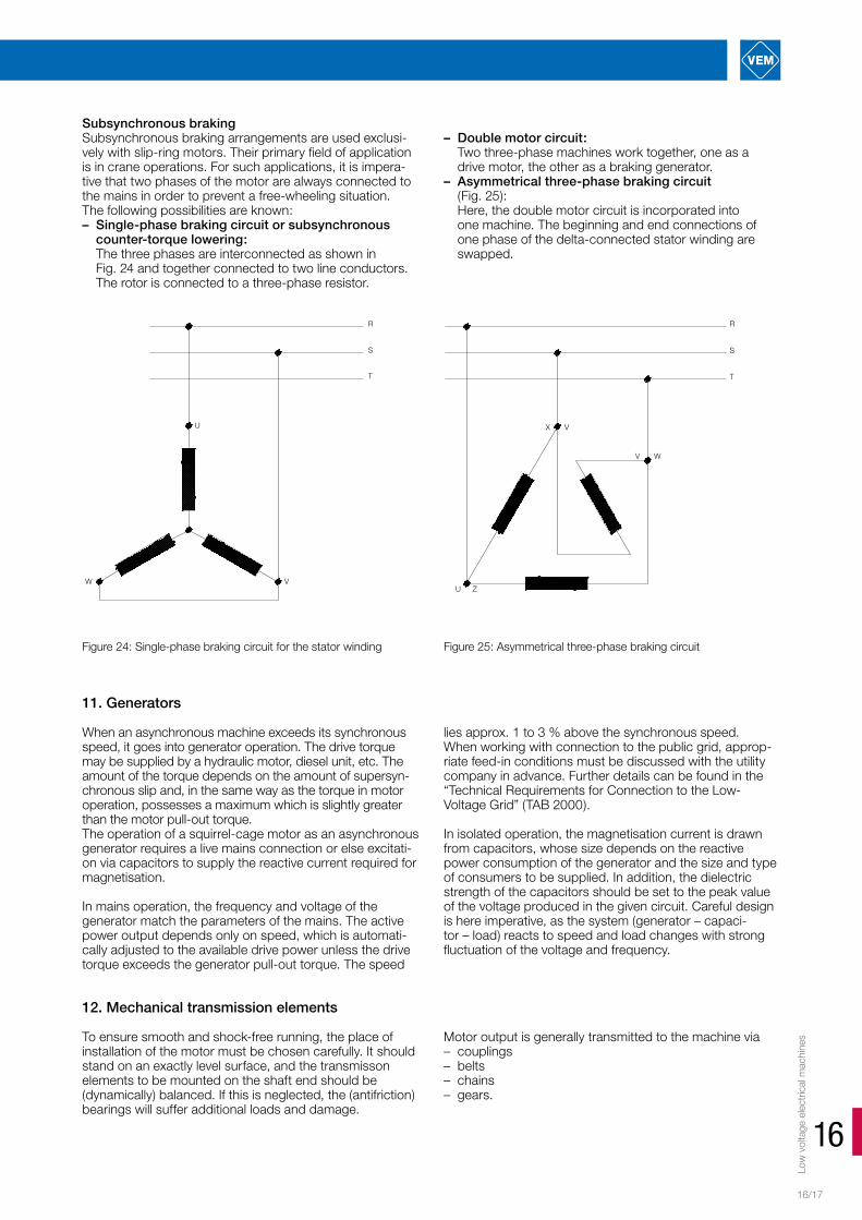
Subsynchronous brakingSubsynchronous braking arrangements are used exclusi-vely with slip-ring motors. Their primary field of application is in crane operations. For such applications, it is impera-tive that two phases of the motor are always connected to the mains in order to prevent a free-wheeling situation. The following possibilities are known:– Single-phase braking circuit or subsynchronous
counter-torque lowering: The three phases are interconnected as shown in Fig. 24 and together connected to two line conductors. The rotor is connected to a three-phase resistor.
– Double motor circuit: Two three-phase machines work together, one as a drive motor, the other as a braking generator.
– Asymmetrical three-phase braking circuit (Fig. 25): Here, the double motor circuit is incorporated into one machine. The beginning and end connections of one phase of the delta-connected stator winding are swapped.
U
W V
R
S
T
U Z
X V
V W
R
S
T
Figure 24: Single-phase braking circuit for the stator winding Figure 25: Asymmetrical three-phase braking circuit
11. Generators
When an asynchronous machine exceeds its synchronous speed, it goes into generator operation. The drive torque may be supplied by a hydraulic motor, diesel unit, etc. The amount of the torque depends on the amount of supersyn-chronous slip and, in the same way as the torque in motor operation, possesses a maximum which is slightly greater than the motor pull-out torque. The operation of a squirrel-cage motor as an asynchronous generator requires a live mains connection or else excitati-on via capacitors to supply the reactive current required for magnetisation.
In mains operation, the frequency and voltage of the generator match the parameters of the mains. The active power output depends only on speed, which is automati-cally adjusted to the available drive power unless the drive torque exceeds the generator pull-out torque. The speed
lies approx. 1 to 3 % above the synchronous speed. When working with connection to the public grid, approp-riate feed-in conditions must be discussed with the utility company in advance. Further details can be found in the “Technical Requirements for Connection to the Low- Voltage Grid” (TAB 2000).
In isolated operation, the magnetisation current is drawn from capacitors, whose size depends on the reactive power consumption of the generator and the size and type of consumers to be supplied. In addition, the dielectric strength of the capacitors should be set to the peak value of the voltage produced in the given circuit. Careful design is here imperative, as the system (generator – capaci-tor – load) reacts to speed and load changes with strong fluctuation of the voltage and frequency.
12. Mechanical transmission elements
To ensure smooth and shock-free running, the place of installation of the motor must be chosen carefully. It should stand on an exactly level surface, and the transmisson elements to be mounted on the shaft end should be (dynamically) balanced. If this is neglected, the (antifriction) bearings will suffer additional loads and damage.
Motor output is generally transmitted to the machine via – couplings– belts– chains– gears.

EinbaumotorenLo
w v
olta
ge e
lect
rical
mac
hine
sGeneral information to aid configuration
16/18
It is up to the designer to find the optimum solution for a particular drive application, taking into account all structu-ral and economic factors. Generally speaking, the outer contours of the transmissi-on elements to be mounted on the motor shaft end must never project beyond the shaft end shoulder, and only standard transmission elements should be used. If self designed parts must be used as an exception, they must nevertheless meet all requirements of the applicable stan-
dards with regard to manufacturing accuracy, balancing, limits of use, etc.The following sections describe the effects of drive element masses and forces (FG in N) on the radial (Fr) and axial forces (Fa) for horizontal and vertical shafts. Where the angle of the motor axis is inclined >15° relative to the hori-zontal/vertical, the force (FG)generated by the mass of the drive elements must be apportioned geometrically to Fr and Fa.
12.1. Coupling drives
Direct couplings are used for most driving and driven machines. Only flexible or special elastic positive couplings should be used. Couplings require very careful aligning of individual machines, i. e. the shaft centres must stand in precise alignment.
Certain inaccuracies in the individual machines may be compensated by the coupling, depending on the type of coupling chosen, but they will nevertheless place con-siderable loads on the bearings and shafts and result in uneven/unsteady running. The result will be greater or lesser destruction of the bearings, motor shafts and transmission elements of couplings. The better the align-ment of machines connected by couplings, the lower the extra loads to be expected and the greater the functional reliability.
Rigid couplings should always be avoided, as they are unable to compensate even the slightest misalignment. As the warming of a cold motor to operating temperature necessarily leads to linear expansion of the shaft, the use of a rigid coupling can already destroy the bearings of the motor or the driven machine after just a short time, and is therefore not authorised by the motor manufacturer.
When using torsionally flexible couplings (plate or bolt couplings), it must be noted that the coupling and the masses it connects form a vibrating system with a certain natural frequency. This natural frequency is reduced by sof-ter couplings and increased by harder ones. Where drives are subject to periodic shocks, it must be ensured that the frequency of the shock moments does not coincide with the natural frequency. Resonance or near-resonance may result in greater vibration amplitudes and loads in the system.
The size of a coupling is selected on the basis of the rated torque on the motor shaft.
where MB = motor rated torque [Nm] P2B = motor rated output [kW] nB = rated speed [rpm]
Operational loads must be taken into account by selecting a coupling of an appropriate size.
12.2. Belt drives
Belt drives are used mainly where– the driving and driven machines must run at
different speeds,– the shafts are not in one plane,– flexible power transmission is needed,– shock and vibration damping is to be achieved.
The most commonly used belts are flat and V-belts in a variety of designs and materials. The preference for one or the other of the two types is dependent on their specific properties and is dealt with in the technical literature.
The following points must be observed when designing belt drives:– Belt pre-tensioning must be adjustable. e. g. by way of
tensioning bars, rolls or rockers.– The shafts of the driving and driven machines must be
exactly parallel.– Where several belts are used on a pulley, endless belts
are recommended. Such belts should be kept in stock and similarly replaced, when necessary, in sets.
horizontal shaft
vertical shaft
(arithmetic addition)
pulling strand
(geometric addition)
FMR
Figure 26: Shaft loading in belt drives

Low
vol
tage
ele
ctric
al m
achi
nes
16
16/19
12.3. Chain drives
Contrary to a belt drive, a chain drive represents a positive transmission element with no slip, even in case of short distances between the axes and high transmission ratios. Compared with gear drives, chain drives are to some extent elastic and are also able to span larger distances between axes without intermediate sprockets.
The radial force acting on the motor shaft end can be determined with
where FrKe = radial force [N] P2B = motor rated output [kW] ck = factor taking into account the additional
force arising in chain drive itself
If the aforementioned measures are observed, uncontrolled reduction of the belt service life of belt systems can be avoided, and premature damage to the driving and driven machines due to uncontrolled loads on the shaft ends and bearings can be averted.
Determining the pulley dimensionsPulleys must be dimensioned such that the permissible values for Fr and Fa on the shaft end are not exceeded. The radial force FrR in belt drives is composed of the pull and the pre-tensioning of the belt. The latter is taken into account with the factor cV when determining FrR.
Approximate values are– 2…2.5 for V-belts– 2.5…3 for standard flat leather belts with tensioning rolls– 4…5 for standard flat leather belts, rubber belts, etc.
without tensioning rolls
The radial force for a given pulley can be determined with
where FrR = radial force [N] P2B = motor rated output [kW] cV = belt pre-tensioning factor nB = motor rated speed [rpm] D = pulley diameter [mm]
The inertia force is calculated as follows: FMR = mR x g where FMR = inertia force [N] mR = pulley weight [kg] g = gravitational acceleration [9.81 ms-2]
Geometric addition is possible for very large pulleys. The effective direction of FrR is invariably towards the driving side. The shaft loads Fr and Fa result as shown in Fig. 28. The dimension x is the distance from the pulley centre to the shaft shoulder. The values Fr, Fa and x can be used to check on the permissibility of loads in accord-ance with the “Technical explanations”.
If the permissible load is exceeded and no significant modi-fication of the load is achieved by choosing a different belt with different pre-tensioning, a pulley with a larger diameter must be selected.
cd = factor taking into account the additional force emanating from the machine
nB = motor rated speed [rpm] D = reference circle diameter of the chain wheel
used [mm]
The effective direction of FrKe is always towards the driving side.On motors with horizontal shafts Fa=0, on vertically oriented motors Fa=FMKe.Fr, Fa and x and determined in the same manner as described in Fig. 28.
FMKe = inertia force of the chain wheel [N]
If the permissible shaft load is exceeded, reference circle diameter of the chain wheel must be increased.
No. of engagements
Type of teeth Factor ck
1 Precision gear wheels (pitch errors/form defects < 0.02 mm)Standard planed/milled gear wheels and chain wheels (error 0.02–0.10 mm) Standard planed/milled gear wheels and chain wheels (error 0.02–0.10 mm)
1.05 … 1.1 1.1 … 1.31.5 … 2.2
2 Precision gear wheels Standard planed/milled gear wheels
0.6 … 0.7 0.7 … 0.8
The lower values apply at low tooth speeds of v ≤ 2 m/s
Factor ck for chain and gear drives

EinbaumotorenLo
w v
olta
ge e
lect
rical
mac
hine
sGeneral information to aid configuration
16/20
Type of machine cd
Prime movers Electric machines, turbines Electric traction motors in locomotive frames Axle-hung electric traction motors, combustion engines, piston steam engines
1.0 … 1.1 1.1 … 1.2 1.2 … 1.5
Transmission systems for driving larger groups of machines
1.1 … 1.3
Conveyors, lifting gear Conveyor belts, ropeways, centrifugal pumps, blowers, turbocompressors Mine fans Elevators, cranes Piston compressors Reciprocating pumps, depending on balancing Hoisting equipment Oscillating conveyors
1.0 … 1.21.1 … 1.31.2 … 1.31.2 … 1.51.5 … 1.61.5 … 1.81.5 … 2.5
Factor cd for chain wheel/gearwheel drives
12.4. Gear drives
Gear drives transmit outputs and speeds without slip and are used above all where the distance between the axes of the driving and driven machines is small and different speeds are required.
Generally, it is possible to distinguish
– straight spur gears, where only radial forces arise in power transmission
– helical spur gears, bevel gears, etc., where both radial and axial forces occur in power transmission
Straight spur gear drivesThe radial force FrZg is determined with
where FrZg = radial force [N] P2B = motor rated output [kW] ck = factor taking into account the additional
force arising in gear drive itself cd = factor taking into account the additional
force emanating from the machine nB = motor rated speed [rpm] DT = reference circle diameter of the gear wheel
used [mm]
The effective direction of the radial force FrZg is shown in Fig. 27.
Figure 27: Effective direction of radial force in spur gears
drivinggear
shared tangent ofboth reference circle
drivengear

Low
vol
tage
ele
ctric
al m
achi
nes
16
16/21
drivengear
driving
line of sight forindication ofdirection of RMd
gear
The radial force FrZg for spur gears always acts under 20° to the joint tangent of the reference circles of the driving and the driven gear.
The following load diagrams take into account the inertia force of the gear FMZ : For gears with high inertia forces, FrZg and FMZ can also be added geometrically.
Helical spur gear drivesWith helical spur gears, radial and axial forces always occur together, though the latter do not act in the motor shaft axis.Where bevel gears, etc. are used, it is also necessary to consult the motor manufacturer and to provide similar values as for helical spur gears.
The following points must always be observed for gear drives:– The shafts of the two machines must be exactly parallel.– The pinion and mating gear must run absolutely true.– The pinion teeth must not seize in any position of the
mating gear.
Figure 29: Mechanical drive for a vertical shaft (straight spur gears)
Figure 28: Mechanical drive for a horizontal shaft (straight spur gears)
Figure 30: Application of force in helical spur gears with corresponding explanations
If these points are neglected, inadmissible bearing loads, vibration, shocks and disturbing noise must be expected. If a paper strip of the same width as the pinion and mating gear is inserted between the two, turning of the gears will reveal any points of misengagement. It must be ensured that all teeth of both wheels are tested in this way. In accordance with the test results, the machine must be realigned as often as is necessary to achieve uniform smooth engagement for all teeth.

EinbaumotorenLo
w v
olta
ge e
lect
rical
mac
hine
sGeneral information to aid configuration
16/22
13. Slip-ring rotors
13.1 Slip-ring motor starting
Slip-ring motors are started almost exclusively by way of a starter which places additional resistors in the rotor circuit.
The starting torque can be varied freely through corres-ponding dimensioning of the starting resistor. The highest attainable starting torque lies at the level of the pull-out torque of the motor; the permissible tolerances for the pull out torque in accordance with IEC/EN 60034-1 must be observed.
The rotor voltage at standstill and the rotor rated current, which are required for determination of the appropriate starting resistors, can be taken from the applicable techni-cal data. If the actual power consumption deviates from the list output, the rotor current can be recalculated as follows:
where I2 = rotor current for actual power consumption I2B = rotor rated current P2 = actual power consumption P2B = rated output
The rotor current which occurs during starting is approxi-mately proportional to the available starting torque and can thus be determined with:
where I2A = starting current in rotor MA = starting torque MB = motor rated torque
The total value of the additional resistors for the rotor circuit is calculated as follows:
I2 = I2B
P2
P2B
13.2.2. Electric braking
With electric braking, the braking torque applied acts in the same direction as the reaction torque of the machine. The resulting braking torque is thus calculated with: MBrRes = MBrm + Mg
where MBrm = mean braking torque
To be able to design a system for electric braking, the following must be known:− max. occurring load torque− moment of inertia to be decelerated− braking time− speed, switching frequency, voltage, frequency
Electric braking functions without wear or special main-tenance. No specific brake is needed, but the switching is more complex. When designing the system, it must be noted that the motor is additionally subject to thermal load.
Counter-current brakingThis form of braking can be used for both squirrel-cage and slip-ring motors. It is realised relatively simply by swapping two of the three three-phase connections. While the centrifugal masses of the drive continue to act in the original direction, the torque already becomes effective in the opposite direction. When the speed reaches zero, the motor must be switched off electrically to avoid a renewed ramp-up in the opposite direction (e. g. by way of a speed monitor). The braking characteristics are dependent on the rotor design.
– For slip-ring motors the braking characteristics are influenced by the incor-poration of additional resistors. Starting and control re-sistors can be used. The braking effect is greatest where the resistances are changed during braking.
I2A = I2B
MA
MB
Figure 31: Starting of slip-ring motors with additional resistors in the rotor circuit
M
MSp
MSch
Mg
n
M
RV1
RV2
RVn
RV =
U20
3 I2B
MB
MA
R2
where U20 = rotor voltage at standstill (from technical data)
R2 = equivalent resistance
For crane motors with slip-rotors, R2 is specified in the technical data. Otherwise, R2 can generally be neglected. If necessary, it can be requested from the manufacturer or calculated in approximation with:
where nS = synchronous speed nB = rated speed
The starting or additional rotor resistors are generally disconnected in steps (manually or with contactor control). The number of steps and the individual switching points should be selected such that only low current and torque peaks result. To this end, a multitude of procedures for both symmetrical and asymmetrical starting circuits are described in the technical literature.
B
B

Low
vol
tage
ele
ctric
al m
achi
nes
16
16/23
Figure 32: Counter-current braking characteristics Figure 33: Counter-current braking characteristics for a slip-ring motor
Regarding the thermal loads placed on the motor, it must be noted that the additional warming is around 2 to 3 times that occurring during starting, particularly for squirrel-cage motors, whereas slip-ring motors produce most of the heat externally in the additional resistor. If braking occurs in conjunction with duty type S5, observe the notes given in section 8.3. The duration of occasional counter-current braking should not exceed 10 secs.
DC brakingFor this type of braking, the stator of the motor is discon-nected from the three-phase mains and subsequently supplied with a direct current after a short interval. The corresponding switching possibilities are shown in Fig. 33. The braking action can be modified by varying the value of the current. The recommended value for the DC braking current is 2 to 2.5 times the motor rated current.
The necessary excitation voltage is calculated with UG = IG · Rges · 1.3
where IG = excitation current (DC) Rges = total resistance, depending on the
braking circuit RPh = phase resistance
The braking characteristic can be derived point by point from the motor characteristics M = f(n) and I1 = f(n).
The braking torque is calculated with:
where M = motor torque K = braking circuit factor I1 = motor current
Through the incorporation of additional resistors into the rotor circuit of a slip-ring motor, it is possible to achieve greater mean braking torques than with a squirrel-cage motor.
The braking action is gentler than in counter-current braking, there are no shocks acting on the gear unit and/or coupling, and there is no subsequent starting in the opposite direction. Additional mechanical braking may be required towards the end of the braking process. Whether braking is better with DC or counter-current braking can only be decided for an individual case. It is without doubt, however, that DC braking offers a thermal advantage, because the resulting losses are approximately the same as for starting. In case of DC braking in duty type S5, the notes given in section 8.3 must be observed for design.
+M
-M
-n +n
Mg
RV1 = O
RV2
RV3
1
3
2
MBR/MBM/MBI1 /I1N
M/MB MBR/MB
1
0
IG/I1N
I1/I1N
n/nSSlip-ring motor

EinbaumotorenLo
w v
olta
ge e
lect
rical
mac
hine
sGeneral information to aid configuration
16/24
13.3. Speed control
Control with additional resistors in the rotor circuitSpeed-controlled slip-ring motors can be supplied for the preferred setting ranges 25 %, 50 % and 75 % and for the reaction torque characteristics Mg = constant, Mg = linear decrease and Mg = quadratic decrease. Due to the poorer efficiency and reduced ventilation, it is not always possible
to achieve the list outputs in operation at speeds below rated speed. The necessary reduction of the standard output, as dependent on the aforementioned parameters, can be taken from the following table.
Speed reduction in %
Output reduction in % of standard output for a given reaction torque characteristic (relative to operation without speed control)
constant linear decrease quadratic decrease25 10 0 050 20 – 25 10 075 45 – 50 25 – 30 0
Speed control with an output reduction of up to 10 % can be realised with slip-ring motors in the basic version. Motors which require an output reduction of more than 10 % are supplied in special design and must be ordered accordingly.
The additional rotor resistors required for the setting range can be determined as follows, taking into account Fig. 34:
where sr = slip for the setting range s = slip for operation without control
for motors in standard design with standard output
for motors in standard design with reduced output
In most cases, it is sufficiently accurate to set s = sB.
for motors in special design with reduced output
where sB = rated slip nS = synchronous speed nB = rated speed (from technical data) M = torque MB = rated torque sBh = rated slip at reduced output with
special design nBh = rated speed at reduced output (see rating
plate or request from the manufacturer) R2 = equivalent resistance of the rotor winding
(for standard version, see technical data; for special designs, consult the manufacturer) R2 warm ≈ 1.3 * R2
As an example, Fig. 35 shows the characteristics of a 6-pole slip-ring motor at 25 % speed setting with linearly decreasing torque.
A modern special version of speed control by way of ad-ditional resistors is electronic power control with a pulsed rotor resistor. The circuit for such control is shown in Fig. 36. The change in motor speed is here realised by way of periodic short-circuiting of the additional resistor, which can be equated to continuous modification of the size of this resistor.
s = sB =
ns nB
nS
s = sB =
MMB
s = sBh =
ns nBh
nS
Figure 34: Torque characteristics for a slip-ring motor with speed control
Figure 35: Example of a motor characteristic for speed control by way of an additional resistor
M
100 75 50 25Sr
MB
M
Mg = constant
Mg = linear decrease
SBS0S/%
Motor characteristic with additional rotor resistor
M
100 75 50 25 0 S/%
Motor characteristic without additional
rotor resistor
Operating point
M
0 250 500 750 1000n/ min-1

Low
vol
tage
ele
ctric
al m
achi
nes
16
16/25
With appropriate control (speed control with secondary two-step current control), it is possible to set any operating point between the limits for permanently short-circuited and permanently active additional resistor. This relatively high outlay, however, is only justified where a demanding technology requires high speed constancy.
Control by way of additional rotor voltagesThe speed of a slip-ring motor can be varied freely in either direction to account for varying load by supplying a
voltage with slip frequency externally to the slip-ring, either in phase with or in phase opposition to the rotor voltage. This principle is well known for electric machines and is realised in practice, for example, in a three-phase shunt wound motor, where the necessary additional rotor voltage is produced internally by way of a commutator.
If the speed control is limited to the subsynchronous range, significant simplification is possible. It is sufficient to with-draw energy from the rotor. The frequency-dependent rotor voltage can be supplied via a power electronics module with DC link. This module serves to return rotor energy to the grid via a line-commutated inverter. The connection diagram of such an arrangement can be seen in Fig. 37.
The basic load characteristics of the aforementioned sub-synchronous converter cascade are shown in Fig. 38. The speed-torque behaviour is characterised by parallel shifting of the curves, where only the straight sections are generally relevant for practical operation.
When designing a drive with speed control, it is almost always necessary to consult the manufacturer, where possible with precise specification of all data which are decisive for the application.
Figure 36: Motor speed control by way of a pulsed rotor resistor
Figure 37: Connection diagram of a subsynchronous converter cascade
Figure 38: Load characteristic of a subsynchronous converter cascade
If a slip-ring motor is operated over a longer period with a load of less than 70 % of the rated output, there is a likelihood of increased brush wear. For this reason, slip-ring motors must be designed such they will not be operated at less than 70 % of the rated output for extended periods.
In exceptional cases, special agreements must be reached with the manufacturer. The work cycle and operating con-ditions must be specified, and appropriate testing may be necessary.
TG
R Rl Rn
nist
nsoll
Z
M3
R S T
R S T
StEg
IgLg
W. R.
M3
S
0
0.5
1M
13.4. Operation of slip-ring motors with low loads

Low
vol
tage
ele
ctric
al m
achi
nes
16/26
EinbaumotorenGeneral information to aid configuration
13.5. Selsyn arrangements
In certain applications where plant is spread over a wide area, as well as for slide rest drives on lathes or loading gantries, for example, it is necessary to maintain synchro-nicity between separate section drives. A mechanical shaft connection is often not feasible due to the physical cir-cumstances. The solution is to simulate a shaft by electric means with a so-called selsyn.
A selsyn is set up by connecting like phases on the stator and rotor sides of two or more slip-ring motors. Depending on the requirements with regard to power transmission, angular positioning, etc., there are two commonly used arrangements, namely the power selsyn (Fig. 39) and the differential selsyn (Fig. 40).
Correct planning of an electric synchronisation arrange-ment requires precise knowledge of the overall system, and in particular of those elements of the drive which interact with the selsyn. This overall view is imperative for proper judgement of the dynamic stability.
The selsyn represents an elastic link between the machine groups, the rotating masses of which are in this way cou-pled as if by torsion springs and can thus display torsional vibration.
It is imperative to check the dynamic behaviour, as proper functioning of the synchronisation arrangement is no longer guaranteed in case of resonances or inadequate damping of the mutual vibration in the drive groups.
Selsyns can be realised through any of a variety of connec-tion possibilities with different static and dynamic proper-ties; details of the different arrangements can be found in the relevant technical literature.Dynamic susceptibility is not necessaryly attributable to the selsyn; it may also result from resonance phenomena in the overall system. Through suitable design measures, e. g. the targeted placement of balancing masses, it may be possible to rectify such susceptibility. To enable the selection of suitable selsyn machines from the available range of slip-ring motor types, the following information must be provided with the order:
– Description of the overall system in terms of type, design, function principle and operating conditions, where related in any way to the selsyn
– Description of the work cycle, specifying the maximum short-time or continuous torques to be transmitted by the selsyn, together with the corresponding speeds and any existing irregularities in the torque
– Information on the type of the main drive motor, especially with regard to ramp-up properties and the response speed for motor speed control
– Maximum permissible rotation angle between the transmitter and the receiver
– Specification of the type of synchronisation (at standstill or running)
– Rotating masses coupled with the selsyn machines in the different operating states.
The following points should be taken into account for preselection of the most suitable variant:
For differential selsyns, rotation in opposition to the rotating field is to be preferred, as this enables the best possible type utilisation. The prerequisite, however, is that the dy-namic stability of the system remains guaranteed. For this reason, it may be necessary to prefer operation with the rotating field under certain circumstances, if the external damping is only very low and there is no alternative to the use of damping resistors for stabilisation. For power selsyns, rotation in the sense of the rotating field is to be preferred. It is only in special cases, e.g. very high speeds up to and above the synchronous speed or reversing operation where reversal of the rotating field is not possible at standstill, that a power selsyn may also be operated with rotation in opposition to the rotating field.
When the selsyn is operated in opposition to the rotating field, the rotor frequency and rotor voltage reach values which do not otherwise occur in normal operation. The iron losses in the rotor are thus higher than usual. In such cases, particular attention must be paid to the thermal behaviour of the selsyn machines. Normal slip-ring motors possess self-ventilation, the intensity of which is naturally reduced at lower speeds. The losses which can be dissi-pated at slow speeds are thus significantly lower than in normal operation. For this reason, considerable limitation of the permissible load is often inevitable. When planning a synchronisation arrangement of any kind, therefore, it is always advisable to consult the manufacturer. In many cases, testing will be imperative.
Figure 40: Differential selsyn
RST
Drive
ReceiverTransmitter
LoadWM1 3
WM2 3
RST
Drive1
Machine set 1
Load2
WM1 3
WM2 3
Load1
Drive2
Machine set 2
Figure 39: Power selsyn

Low
vol
tage
ele
ctric
al m
achi
nes
16
16/27
No claims are raised as to the completeness of the informa-tion on motor configuration and corresponding applications provided in this chapter. This information is intended merely to help the user to understand drive problems and to confi-dently preselect a suitable three-phase electric motor for the given drive application. All information has been gathered and checked with the utmost care. Nevertheless, we are un-able to accept liability of any kind regarding possible errors, omissions or inconsistencies.
Wherever our customers need electric machines, we are at hand as a partner and offer every necessary support at all phases of a project. It is not important whether you are do-ing business in Europe, the Middle East, Asia or America. As the VEM market share increases also outside Germany, we are expanding our sales network with a combination of own subsidiary companies and strategic alliances. Already today, our customers can address their questions to competent and experienced local partners all over the world. Alongside VEM subsidiaries in Finland, Great Britain, Norway, Austria and Singapore, we have established a dense network of sales and service contacts with agents and representatives in more than 40 countries.

Einbaumotoren
16/28
Low-voltage machines Three-phase asynchronous motors with squirrel-cage rotor up to 710 kW as energy saving motors in efficiency classes IE3, IE2, IE1 according to IEC/EN 60034-30-1/IEC 60034-2-1Three-phase asynchronous motors with slip ring rotor up to 315 kWRoller table motors up to 710 kWExplosion-protected motors up to 630 kWCrane motors and marine motorsSpecial motors with brake, forced ventilator, encoderCompact drives up to 22 kWBuilt-in motorsThree-phase asynchronous generators High-voltage machinesHigh-voltage asynchronous motors up to 28 MWHigh-voltage synchronous motors up to 42 MWHigh-voltage synchronous generators to 45 MVATraction machinesWind power generators up to 7 MW
Foundry productsCustom-made castingsFittings, Valves, HydrantsArchitectural casting
Further information about our delivery program and our product range you can find in the Internet under www.vem-group.com
You can also request a copy of our electronic catalogue on a USB stick.
VEM-Product Range
Technical modificationWe strive to improve our products whenever and wherever possible. Consequently, technical data and illustrations remain subject to change. Specifications may only be considered binding following written confirmation by the supplier
Liability, duty to obtain a permitAll information are without any engagement. For printing errors we don`t take over any liability.
Copies, reprints, saving files or publication are only possible with specific acceptance of VEM motors GmbH.
The products featured in this catalogue are also contained in our interactive VEM catalogue.
Further information on the companies and products of the VEM Group can be found at www.vem.group.com.
The electronic catalogue VEMeKAT assists you in the selection and configuration of VEM products. You are able to print out both data sheets and product enquiries, while dimensioned and scale drawings can be displayed or exported in various 2D and 3D formats. In addition to general information about the VEM Group, you have direct access via the program to catalogues, spare parts lists, operating and maintenance instructions, test certificates and circuit diagrams of the individual products.
Einbaumotoren

For detailed information please visit our website.
www.vem-group.com
VEM Holding GmbH
Pirnaer Landstraße 176 01257 Dresden Germany
Sales
Low voltage department
Tel. +49 3943 68-3127 Fax +49 3943 68-2440 E-mail: [email protected]
High voltage department
Tel. +49 351 208-3237 Fax +49 351 208-1108 E-mail: [email protected]
Drive systems department
Tel. +49 351 208-1180 Fax +49 351 208-1185 E-mail: [email protected]
VEM Service
Tel. +49 351 208-3237 Fax +49 351 208-1108 E-mail: [email protected]
VMUK_NS02-116-EN-2/17 Printed in Germany. Subject to change.
© 2017 Juniks Marketing GmbH