ANNEX A - BIM PRACTICAL EXAMPLE - UPCommons A.pdf · ANNEX A – BIM Practical Example 1 1 ANNEX A...
108
ANNEX A – BIM Practical Example 1 1 ANNEX A - BIM PRACTICAL EXAMPLE TABLE OF CONTENTS A.1. Development of a building project with BIM ........................................................................ 6 A.1.1. Introduction ................................................................................................................. 6 A.1.2. Tools and methodology ............................................................................................... 7 A.1.3. Building description ..................................................................................................... 7 A.1.4. Model development: Design process simulation ........................................................ 9 A.2. Structural model .................................................................................................................. 11 A.2.1. Introduction .............................................................................................................. 11 A.2.2. Preliminary structural design .................................................................................... 11 A.2.3. Preliminary structural design based on CAD files ..................................................... 12 A.2.4. Structural elements: Design methodology ............................................................... 13 A.2.5. Suspended floor: Design and dimensioning .............................................................. 14 A.2.6. Creation of a precast concrete slab parametric family ............................................. 18 A.2.7. Structural roof: Design and dimensioning ................................................................ 21 A.2.8. Creation of a composite metal deck parametric class .............................................. 24 A.2.9. Structural steelwork: Design and dimensioning ....................................................... 27 A.2.10. Structural steelwork connections: Design and dimensioning ................................. 36 A.2.11. Structural steelwork design: Change management ................................................ 41 A.2.12. Structural steelwork design: Analysis results import .............................................. 43 A.2.13. Foundations: Design and dimensioning .................................................................. 44 A.2.14. Foundation system design: Analysis results import ................................................ 52 A.2.15. Enclosing elements: Design methodology .............................................................. 54 A.2.16. External wall design ............................................................................................... 54 A.2.17. Creation of an external wall parametric class ......................................................... 57 A.2.18. Retaining foundation wall design: waterproofing and ventilation ......................... 59 A.2.19. Roof finishing layers design..................................................................................... 60 A.2.20. Creation of a roof parametric class: Composite metal deck update ...................... 63 A.2.21. Modelling of roof geometry .................................................................................... 64 A.2.22. Model coordination with architectural designers................................................... 65 A.3. Architectural model ............................................................................................................. 67 A.3.1. Introduction .............................................................................................................. 67 A.3.2. Linking the structural model ..................................................................................... 67
Transcript of ANNEX A - BIM PRACTICAL EXAMPLE - UPCommons A.pdf · ANNEX A – BIM Practical Example 1 1 ANNEX A...
ANNEX A – BIM Practical Example 1
1
ANNEX A - BIM PRACTICAL EXAMPLE
TABLE OF CONTENTS
A.1. Development of a building project with BIM ........................................................................ 6
A.1.1. Introduction ................................................................................................................. 6
A.1.2. Tools and methodology ............................................................................................... 7
A.1.3. Building description ..................................................................................................... 7
A.1.4. Model development: Design process simulation ........................................................ 9
A.2. Structural model .................................................................................................................. 11
A.2.1. Introduction .............................................................................................................. 11
A.2.2. Preliminary structural design .................................................................................... 11
A.2.3. Preliminary structural design based on CAD files ..................................................... 12
A.2.4. Structural elements: Design methodology ............................................................... 13
A.2.5. Suspended floor: Design and dimensioning .............................................................. 14
A.2.6. Creation of a precast concrete slab parametric family ............................................. 18
A.2.7. Structural roof: Design and dimensioning ................................................................ 21
A.2.8. Creation of a composite metal deck parametric class .............................................. 24
A.2.9. Structural steelwork: Design and dimensioning ....................................................... 27
A.2.10. Structural steelwork connections: Design and dimensioning ................................. 36
A.2.11. Structural steelwork design: Change management ................................................ 41
A.2.12. Structural steelwork design: Analysis results import .............................................. 43
A.2.13. Foundations: Design and dimensioning .................................................................. 44
A.2.14. Foundation system design: Analysis results import ................................................ 52
A.2.15. Enclosing elements: Design methodology .............................................................. 54
A.2.16. External wall design ............................................................................................... 54
A.2.17. Creation of an external wall parametric class ......................................................... 57
A.2.18. Retaining foundation wall design: waterproofing and ventilation ......................... 59
A.2.19. Roof finishing layers design ..................................................................................... 60
A.2.20. Creation of a roof parametric class: Composite metal deck update ...................... 63
A.2.21. Modelling of roof geometry .................................................................................... 64
A.2.22. Model coordination with architectural designers................................................... 65
A.3. Architectural model ............................................................................................................. 67
A.3.1. Introduction .............................................................................................................. 67
A.3.2. Linking the structural model ..................................................................................... 67
ANNEX A – BIM Practical Example 2
2
A.3.3. Modelling of interior design ...................................................................................... 69
A.3.4. Study of alternatives: Window disposition ............................................................... 74
A.3.5. Building accesses design ........................................................................................... 79
A.3.6. Study of alternatives: Internal space distribution ..................................................... 80
A.3.7. Visualisation of final design: Cameras, Renders and Walkthroughs ......................... 83
A.4. Construction model ............................................................................................................. 85
A.4.1. Introduction .............................................................................................................. 85
A.4.2. Construction site ...................................................................................................... 86
A.4.3. Health and safety measures ..................................................................................... 90
A.4.4. Linking models to the construction site .................................................................... 91
A.4.5. Construction phases .................................................................................................. 92
A.4.6. Evaluation of construction tasks ............................................................................... 94
A.4.7. Schedule generation ................................................................................................. 98
A.4.8. Urbanisation design .................................................................................................. 99
A.5. Coordination model ........................................................................................................... 101
A.5.1. Introduction ............................................................................................................ 101
A.5.2. Coordination examples ........................................................................................... 101
REFERENCES .............................................................................................................................. 107
TABLE OF FIGURES
Figure 1: From left to right: Linked CAD file; Approach to foundation and column design ........ 12
Figure 2: From left to right and top to bottom: Updated linked CAD file; Approach to foundation
and column design; Updated approach to foundation and column design ................................ 13
Figure 3: Foundation system preliminary design ........................................................................ 14
Figure 4: Hollow core section slab PF15.XX cross section [14] .................................................... 16
Figure 5: Hollow core section slabs with reinforced concrete topping: Cross section and self-
weight values [14] ....................................................................................................................... 16
Figure 6: Hollow core section slab geometric data implementation process: Paper based; CAD;
BIM .............................................................................................................................................. 19
Figure 7: Suspended floor support conditions at column base connections ............................... 20
Figure 8: From left to right: Parametric definition of void forms; Resulting slab edge trims ..... 20
Figure 9: Slab disposition according to column base accommodation ....................................... 21
Figure 10: Structural roof preliminary design ............................................................................. 22
Figure 11: Metallic profile modelling .......................................................................................... 25
Figure 12: Composite metal deck family class’ structural layers ................................................ 26
Figure 13: Composite metal deck assembly cross-section .......................................................... 26
Figure 14: Structural steelwork preliminary design .................................................................... 27
ANNEX A – BIM Practical Example 3
3
Figure 15: Analytical model of structural steelwork; Details with superposed physical model .. 29
Figure 16: From left to right: Analytical model defined in Revit; Analytical model exported to
RSA .............................................................................................................................................. 30
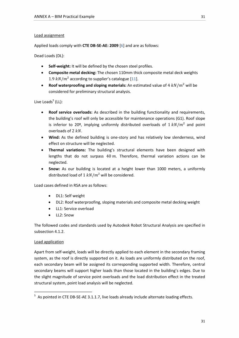
Figure 17: Load application in RSA model for load case DL2 ...................................................... 32
Figure 18: Structural analysis results: Bending moment diagrams (RSA) ................................... 32
Figure 19: Structural analysis results: Bending moment diagrams for updated model .............. 33
Figure 20: Assignation of lateral buckling constraints in RSA ..................................................... 33
Figure 21: Results of the second steelwork profile optimisation process ................................... 35
Figure 22: Steelwork column base plate connection modelled in RSA ........................................ 36
Figure 23: Steelwork column base plate connection imported to Revit ...................................... 37
Figure 24: Framing system support connection details [10] ....................................................... 37
Figure 25: Catalogue steelwork connections modelled in Revit .................................................. 38
Figure 26: Steelwork framing system: connection details ........................................................... 39
Figure 27: 3D view of shear bolt connector for composite metal decks ..................................... 40
Figure 28: Drafting view of composite metal deck connection ................................................... 41
Figure 29: From left to right: Preliminary design structural model; Updated structural model . 41
Figure 30: Updated analytical model of structural steelwork; superposed physical model ....... 42
Figure 31: Suspended floor slab details for column base accommodation ................................. 43
Figure 32: Structural analysis results: Bending moment diagrams (Revit) ................................. 43
Figure 33: Steelwork structure base reactions (ULS combined) .................................................. 46
Figure 34: Representation of load application and distribution for the foundation system ....... 47
Figure 35: Column footing layout by group ................................................................................. 48
Figure 36: Foundation design settings dialogue in RSA .............................................................. 49
Figure 37: Footing preliminary design ......................................................................................... 49
Figure 38: Optimised corner footing dimensions ........................................................................ 50
Figure 39: Optimised perimeter footing dimensions ................................................................... 50
Figure 40: Optimised internal footing dimensions ...................................................................... 50
Figure 41: From left to right: External foundation wall preliminary design; internal foundation
wall preliminary design ............................................................................................................... 51
Figure 42: From left to right: External foundation wall design settings; internal foundation wall
design settings ............................................................................................................................. 51
Figure 43: Optimised external wall dimensions .......................................................................... 52
Figure 44: Optimised internal wall dimensions ........................................................................... 52
Figure 45: Import of steel reinforcement from RSA to the Revit structural model ..................... 53
Figure 46: Layout of modelled foundation system ...................................................................... 53
Figure 47: External wall class properties dialogue ...................................................................... 57
Figure 48: From left to right: External wall cross sectional view; External wall section plan view
..................................................................................................................................................... 58
Figure 49: General view of external wall modelled class with no openings ................................ 58
Figure 50: Retaining foundation wall class properties dialogue ................................................. 59
Figure 51: Extension of retaining foundation walls through parametric constraints ................. 60
Figure 52: Definition of material appearance dialogue .............................................................. 63
Figure 53: Roof sloping system with detail ................................................................................. 64
Figure 54: Illustrative guttering system ...................................................................................... 65
ANNEX A – BIM Practical Example 4
4
Figure 55: Provisional openings in structural model ................................................................... 66
Figure 56: General view of linked structural model .................................................................... 68
Figure 57: From left to right: Internal building view showing steelwork structure; clear internal
building view ............................................................................................................................... 69
Figure 58: Modelling of interior walls based on linked CAD file .................................................. 69
Figure 59: Render appearance of PVC floor finishing layer ......................................................... 70
Figure 60: Pre-defined office furniture object components ........................................................ 70
Figure 61: Pre-defined common area furniture object components ........................................... 71
Figure 62: From left to right: Blocked door in preliminary design; modified door family class .. 71
Figure 63: From left to right: Model view of commercial reception desk; Rendered view of
commercial reception desk.......................................................................................................... 72
Figure 64: Placement of commercial reception desk object instance ......................................... 73
Figure 65: Commercial office furniture object components ........................................................ 73
Figure 66: Interior views of first window disposition alternative ................................................ 74
Figure 67: Façade views of first window disposition alternative ................................................ 75
Figure 68: Interface view of sun path analysis settings .............................................................. 75
Figure 69: Project location dialogue for sun path analysis ......................................................... 76
Figure 70: Day light simulation for Eastern façade window: Interior and exterior views ........... 76
Figure 71: Interior views of second window disposition alternative ........................................... 77
Figure 72: Façade views of second window disposition alternative ........................................... 77
Figure 73: Elevation view of Northern façade: Windows placed at average user height ........... 78
Figure 74: Parametric definition of wall openings ...................................................................... 78
Figure 75: From top to bottom: General views of building accesses; perspective view of main
building access ............................................................................................................................ 79
Figure 76: First space distribution alternative: Interior view 1 ................................................... 80
Figure 77: First space distribution alternative: Interior view 2 ................................................... 81
Figure 78: Second space distribution alternative: Interior view 1 ............................................... 82
Figure 79: Second space distribution alternative: Interior view 2 ............................................... 82
Figure 80: Definition of a ‘Camera’ model view .......................................................................... 83
Figure 81: From top to bottom: Interior ‘camera’ model view; rendered interior model view ... 84
Figure 82: Definition of a ‘Walkthrough’ model view’s path within the model .......................... 84
Figure 83: From left to right: Project location dialogue; Cooling Design Temperatures provided
by Revit ........................................................................................................................................ 86
Figure 84: Modelled site topography: Topographic mesh and contour lines .............................. 87
Figure 85: Site topography: Detail of ‘property line’ definition for the building’s lot ................ 87
Figure 86: Site topography: Detail of ‘property line’ definition for the building’s lot ................. 88
Figure 87: From left to right: Plan view of disruptive original topography; Plan view of
excavated topography................................................................................................................. 88
Figure 88: From left to right and top to bottom: Disruptive original topography; Excavated
topography; Defined ‘graded region’ highlighted in red; defined ‘building pad’ ........................ 89
Figure 89: Modelled site conditions: Inclusion of construction-related object instances ........... 90
Figure 90: Safety barrier object instances surrounding building’s pad ....................................... 90
Figure 91: Signalling cable object instances placed on top of terrain slope ............................... 91
Figure 92: Plan view of the construction model’s centre point ................................................... 91
ANNEX A – BIM Practical Example 5
5
Figure 93: From left to right: Pre-defined crawler crane object instance; Pre-defined concrete
pump object instance .................................................................................................................. 94
Figure 94: Evaluation of crawler crane’s reach capacity from different positions ...................... 95
Figure 95: Evaluation of concrete pump’s reach capacity from different positions .................... 96
Figure 96: General views of a commercial excavator object instance ........................................ 97
Figure 97: Evaluation of scaffolding layout in the construction model ....................................... 97
Figure 98: Rendered view of building’s surrounding urbanisation .............................................. 99
Figure 99: Rendered view of building’s Eastern façade ............................................................ 100
Figure 100: Ventilation duct connecting restroom with the exterior ........................................ 102
Figure 101: Interference check setup dialogue ......................................................................... 103
Figure 102: Interference check warning report ......................................................................... 103
Figure 103: Clash detection for ventilation duct: Colliding elements are highlighted in orange
................................................................................................................................................... 104
Figure 104: From left to right and top to bottom: Initial duct position; coordinated duct
position; initial suspended ceiling height; coordinated suspended ceiling height .................... 104
Figure 105: From top to bottom: Initial layout of ventilation openings; Interference with
building access ramps ............................................................................................................... 104
Figure 106: Coordinated layout of ventilation openings ........................................................... 104
TABLE OF TABLES
Table 1: Building design aspects categorised by field: Treated aspects are highlighted in green 9
Table 2: Mechanical and strength resistance properties of hollow core section slab systems [14]
..................................................................................................................................................... 18
Table 3: Composite metal deck physical properties .................................................................... 23
Table 4: Admissible loads other than self-weight for ‘EUROCOL 60’ metal deck (daN/m²) ........ 24
Table 5: Generic ‘F1.4’ wall section. Extracted from CTE catalogue for constructive components
[13] .............................................................................................................................................. 55
Table 6: Physical properties of external wall layer materials ...................................................... 56
Table 7: Generic ‘C 5.8’ roof section. Extracted from CTE catalogue for constructive components
[13] .............................................................................................................................................. 61
Table 8: Physical properties of roof finishing layer materials ..................................................... 62
Table 9: Commercial ‘S_con’ office chair pricing list ................................................................... 73
ANNEX A – BIM Practical Example 6
6
A.1. DEVELOPMENT OF A BUILDING PROJECT WITH BIM
A.1.1. Introduction
All of AEC industry projects are developed in an attempt to cover the necessities of owner
stakeholder parties. Project definition at initial phases of the project lifecycle is essential to
carry out designs that comply with desired cost, program, quality and functional requirements.
The practical example developed in this work aims to simulate a feasible real-life scenario
where an edification project design is developed within Building Information Modelling
processes and workflows. In accordance with this objective, an initial description of the
building’s functional requirements and features will be offered, as if it was delivered by owner
stakeholder parties. Based on this initial description, the work of several disciplinary designers
will be thoroughly explored in the development of various BIM models. With the assistance of
these disciplinary models, each design player’s point of view can be easily represented in
terms of their competence over project design, interaction with other project players and
deliverables expected as outcome of their work.
The capabilities offered by the use of BIM technology will be revised and explained through
the practical realisation of comprehensive examples. As the functionalities of BIM technology
are oriented to a wide range of AEC project players, specific tools will be described for each
disciplinary model.
Furthermore, as the realisation of the building’s design takes place, interaction between
project players will be simulated in order to exemplify how Building Information Modelling
enables new processes and workflows with respect to traditional AEC industry practices.
In summary, the author has decided to develop a practical example in response to the
following purposes:
Put into practice some of the most important concepts regarding BIM use.
Familiarise with the use of BIM software platforms in order to learn and explore their
capabilities.
Develop a basic, but technically consistent, model of a building project.
The practical realisation of these examples is not to be taken lightly. Considerable amount of
time and effort have been put in learning and familiarising with the use of BIM software and
their conceptual fundamentals. The author has completed several tutorials from diverse
sources and developed complex examples which have not been included in this work in order
to master BIM software use so that all relevant BIM capabilities exposed herein can be
accurately described. It is important to highlight that the author has intended to go beyond the
particularities of BIM software use. The main focus of attention has been put on offering a
holistic vision of how the enabled new processes and workflows would possibly fit a real-life
edification project. Therefore, the following content is not a mere Revit tutorial, but an
exploration of Building Information Modelling as a process.
ANNEX A – BIM Practical Example 7
7
A.1.2. Tools and methodology
The practical examples developed in this work will be generated in the ‘Autodesk Revit 2014’
BIM platform. This software title has been chosen by the author for the following reasons:
Availability of student licences.
Availability of intermediate to advanced tutorials.
Existence of a direct link with ‘Autodesk Robot Structural Analysis’ structural analysis
software.
Wide downloadable content suitable for Revit in on-line BIM object libraries.
Integrated multi-disciplinary coverage and tools in the same platform.
Wide range of tools common to most BIM platforms
Note that it is not the author’s intention to promote or publicise any particular BIM software
platform title in any way. As far as possible, the author has developed practical examples using
tools which are common to most BIM software titles, and stating where necessary if a
particular tool is exclusive of Autodesk Revit. Therefore, in the development of this work
generality has been kept for most part of exposed BIM technology capabilities.
A.1.3. Building description
The owner parties involved in the project have developed a preliminary functional plan for the
building to be constructed. The requirements and preliminary data to be considered are as
follows:
Location
The project will be located in the surroundings of Barcelona, Spain. Note that for the purpose
of this work no specific location has been defined in order to keep examples as general and
comprehensive as possible. Barcelona will only be used as an approximate location for the
design of building’s closing elements with regard to the use of weather and height
environmental conditions.
Site
The project will be allocated within a 1760 m² building plot. An area of 270 m² pertaining to
the owner’s property is available and qualified for edification according to urbanism
regulations.
Basic functionality
The designed building must serve both as an office facility and as a storage space. This
combined functionality may correspond to various purposes. For instance, the building may be
a logistics intermediate asset within a distribution chain, where products are temporarily
stored and their delivery managed and controlled in the same office facilities. The building
ANNEX A – BIM Practical Example 8
8
could also correspond to an infrastructure’s maintenance operation centre as well, with offices
to coordinate and manage maintenance efforts and available storage space for necessary
equipment. As several realistic uses can be found to justify the project’s requirements no
specific purpose will be determined from now on in order to keep the work’s generality.
Building geometry and structural typology
Building’s plan geometry must be based on straight perpendicular lines and enclosed by four
main facades. The building must have a unique story with no particular height limitations. No
perimeter bounding limitations are found in terms of foundation design.
Building must have a two door main access to the office facilities and two main accesses to the
storage area. Windows must represent at least 15% of total façade surface.
The building’s roof is to be flat and must be supported by structural steelwork. A suspended
floor with precast concrete elements will be designed.
Building space distribution requirements
Internal building space must contain all of the following areas and comply with the specified
requirements as follows:
Office area: Must have at least a 70 m² surface and hold a minimum quantity of 7 desk
spaces.
Reception area: Must give access to the building and have at least a 15 m² surface.
Meeting room: Must have at least a 20 m² surface.
Restroom: Must have at least a 12 m² surface and be sufficiently equipped for building
occupancy.
Social area: Must have at least a 20 m² surface.
Storage area: Must have at least a 70 m² surface and have a minimum of two main
exterior accesses.
Building urbanisation requirements
Building’s surrounding urbanisation must include a parking area adjacent to the storage area
and must be connected to the closest road or highroad. Both the building and the parking area
must be enclosed by appropriate pedestrian sidewalks which lead to office facility’s access.
The remaining unused surface of the building’s property plot will be destined to gardening and
landscaping.
The requirements for the building’s parking lot are as follows:
Parking must have at least a 600 m² surface and hold a minimum of 7 parking spaces
and 2 parking spaces for the disabled.
Special requirements
All designed facilities are to be accessible to the disabled. Building access must be
suited for wheelchairs and restroom facilities must provide adequate equipment.
ANNEX A – BIM Practical Example 9
9
A.1.4. Model development: Design process simulation
Based on the project’s preliminary prescriptions and requirements several Building
Information Models will be developed for its design. In an attempt to simulate the design
process, the different parts and disciplines that compose a project’s definition will be treated
in a logical sequence.
To begin with, it is important to state which aspects of design will and will not be developed, as
edification projects involve a very wide range of disciplines, building components and
processes.
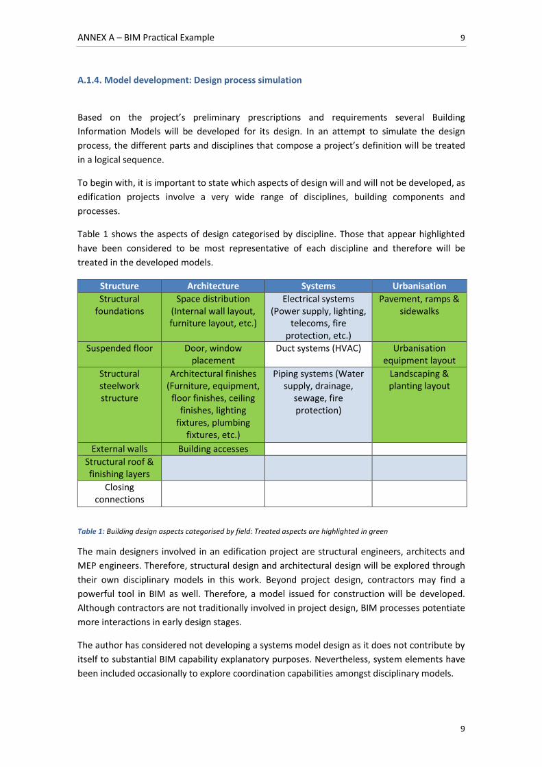
Table 1 shows the aspects of design categorised by discipline. Those that appear highlighted
have been considered to be most representative of each discipline and therefore will be
treated in the developed models.
Structure Architecture Systems Urbanisation
Structural foundations
Space distribution (Internal wall layout, furniture layout, etc.)
Electrical systems (Power supply, lighting,
telecoms, fire protection, etc.)
Pavement, ramps & sidewalks
Suspended floor Door, window placement
Duct systems (HVAC) Urbanisation equipment layout
Structural steelwork structure
Architectural finishes (Furniture, equipment,
floor finishes, ceiling finishes, lighting
fixtures, plumbing fixtures, etc.)
Piping systems (Water supply, drainage,
sewage, fire protection)
Landscaping & planting layout
External walls Building accesses
Structural roof & finishing layers
Closing connections
Table 1: Building design aspects categorised by field: Treated aspects are highlighted in green
The main designers involved in an edification project are structural engineers, architects and
MEP engineers. Therefore, structural design and architectural design will be explored through
their own disciplinary models in this work. Beyond project design, contractors may find a
powerful tool in BIM as well. Therefore, a model issued for construction will be developed.
Although contractors are not traditionally involved in project design, BIM processes potentiate
more interactions in early design stages.
The author has considered not developing a systems model design as it does not contribute by
itself to substantial BIM capability explanatory purposes. Nevertheless, system elements have
been included occasionally to explore coordination capabilities amongst disciplinary models.
ANNEX A – BIM Practical Example 10
10
In summary, the content of this practical example is organised under various BIM models as
follows:
Structural model
Architectural model
Construction model
Coordination model
Apart from exploring BIM tools and capabilities, each model subsection has been organised in
a way such that it follows a logical design sequence. All models are related to each other in
order to reflect the possible interactions and collaborations amongst project players.
All complementary documentation and examples developed with regard to the practical
example have been compiled in ANNEX B of this work.
ANNEX A – BIM Practical Example 11
11
A.2. STRUCTURAL MODEL
A.2.1. Introduction
Structural engineers may find it very helpful to use BIM in design stages. Whenever project
conceptualisation is developed, structural analysis is essential to back up the design intent.
Once project features and requirements are clearly defined, structural analysis is the next logic
step towards delivering detailed BIM models for construction.
In the development of the structural model for this section, the role of structural engineers will
be represented. A preliminary design of the project developed by architectural designers and
based on owner’s requirements will be used to conceptualise and develop the structural
system of the building. This workflow has been used to represent the possible concurrent
collaboration in early design stages between architects and structural engineers. The influence
of contractors in the development of the current model has been also represented through
some decisions regarding building component selection.
While structural elements are conceptualised, modelled and verified, the structural model will
be linked to an architectural model. This intends to represent real-time collaboration amongst
both players. Important changes regarding structural design may affect architectural solutions.
When both structural and architectural design are detailed enough and coordinated amongst
each other, a joint model will be linked to a contractor’s model issued for construction.
A.2.2. Preliminary structural design
Building scope is defined by owners in the very first steps of project development. Usually, the
basic functionalities and requirements of a project are reflected on a preliminary design. In this
sub-section an early-stage design workflow carried out by structural engineers will be
explored.
For the scope of this work, a preliminary CAD based design has been created for the described
building. It contains fairly basic architectural information, and it has been assigned to
structural engineers to dimension the supporting building structure and its lay-out in order to
evaluate structural feasibility. This would represent a scenario where the owner’s team is not
still familiar with BIM use and still works with CAD based information. If the owner provided a
preliminary BIM model instead, it could be linked to the structural model as well.
Based on the preliminary design, a one story square 15x15 meter base building is to be built.
At first sight intermediate supports for the roof will be necessary, as 15 meters is a fairly long
span for conventional framing. Structural steelwork will be used for supporting the building. Its
columns will be placed in gridline intersections, generating smaller 5 meter spans for the
framing system. This way, columns align with designed walls and do not disrupt space
distribution.
ANNEX A – BIM Practical Example 12
12
The framing system to be built will depend on the kind of structural roof support solution. In
this case, composite metal decking will be adopted, as contractor may claim shorter execution
times and satisfactory results in previous projects. This kind of interaction is possible if
contractors collaborate in early design stages. Composite metal decking does not allow for
long spans, creating a need for a secondary framing system running perpendicularly on top of
a primary one. This generates smaller spans that are more suitable for roof support.
Defining building structure will lead to foundation design and dimensioning. In this initial stage
a conceptual foundation system can be defined. Isolated column footings will be tied by
ground beams in both orthogonal directions. As they are below ground level, retaining
concrete walls will be placed on top of foundations to support the suspended floor at ground
level. Precast hollow core section concrete slabs will be used for the suspended floor. Again,
this may be influenced by the collaboration with contractors or subcontractors in the design
process.
A.2.3. Preliminary structural design based on CAD files
CAD files can be linked to BIM models in order to assist in their 3-Dimensional development.
For this example, the CAD files describing a preliminary design will be linked to the structural
model. Links allow synchronisation of files, so if any change is made to the CAD drawing, it will
be propagated to the BIM model.
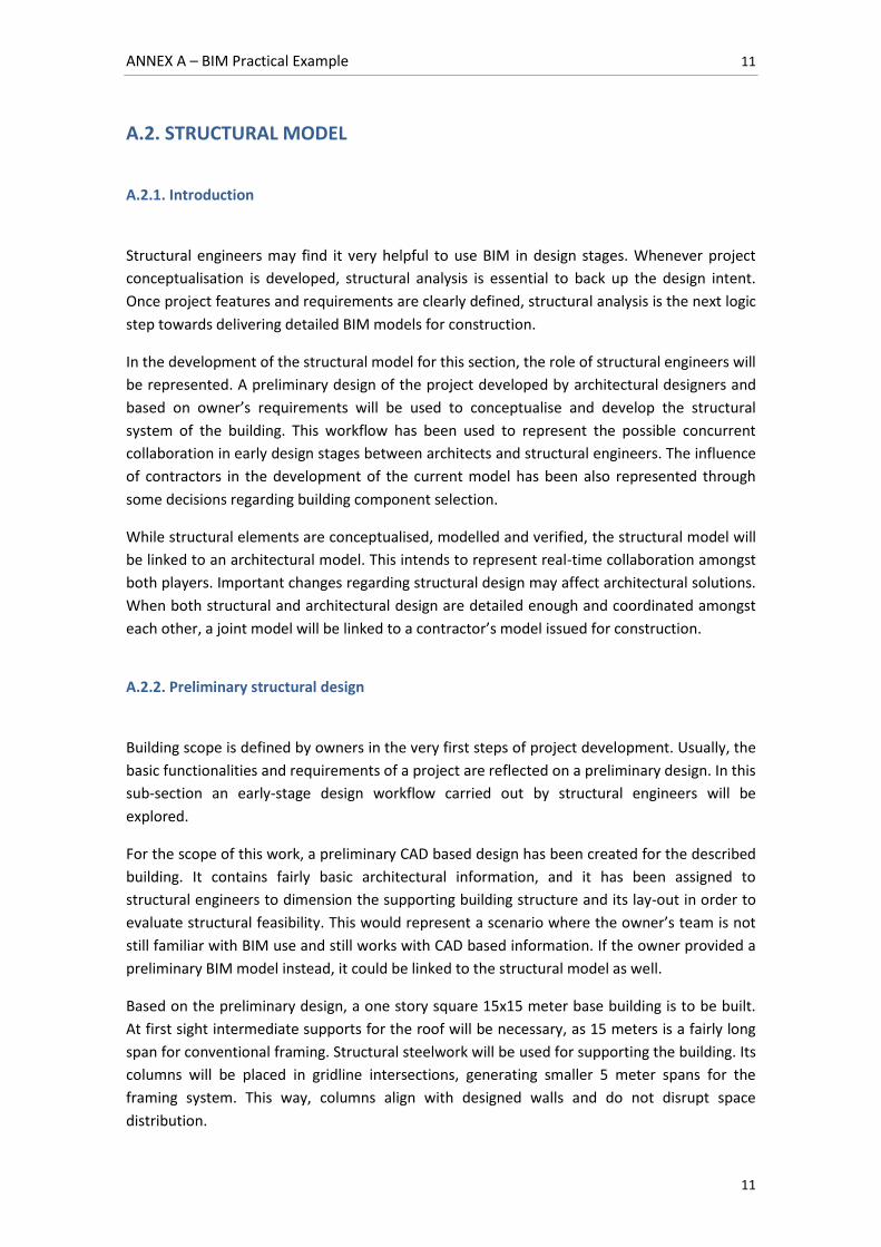
Before any modelling effort takes place, gridlines and levels are defined so that design takes
place in an organised way. A first approach to building foundations and structural steelwork
columns is made, as shown in Figure 1.
Nevertheless, if preliminary structural design starts concurrently with conceptual design,
relevant changes to the building definition may take place. As an example, the owner may
have decided to incorporate a reception at the building’s entrance and change the location of
restroom facilities, making it necessary for changes to the structural model. Once the
Figure 1: From left to right: Linked CAD file; Approach to foundation and column design
ANNEX A – BIM Practical Example 13
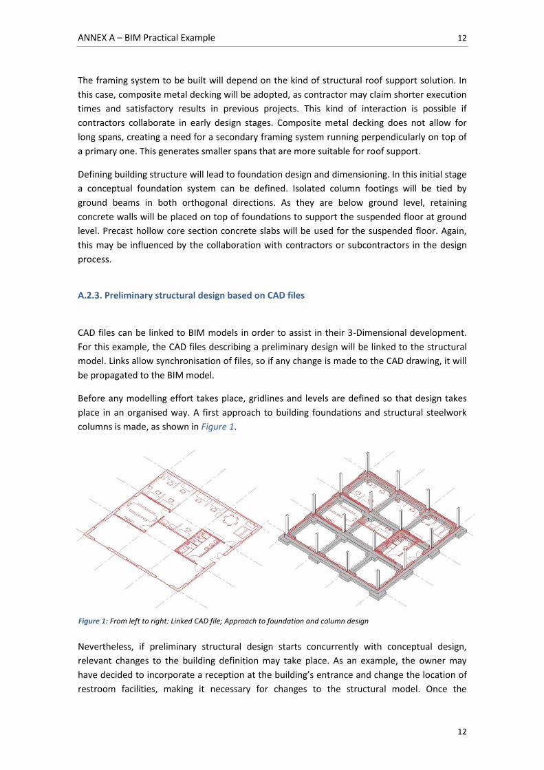
13
preliminary design CAD file is modified, changes automatically propagate to the linked
representation in the model, as shown in Figure 2. Although these kinds of changes do not
usually occur due to urban planning code regulations, they serve as a good example for
illustrating how changes to model definition can be thoroughly managed.
When evaluated, modifications can be validated and the modelling of the building structure
may proceed. In the following sections, structural element dimensioning and verification are
exposed in greater detail.
A.2.4. Structural elements: Design methodology
The structural model can be broken down in four fairly basic structural systems:
Roof deck
Structural steelwork
Suspended floor
Foundations
Figure 2: From left to right and top to bottom: Updated linked CAD file; Approach to foundation and column design; Updated approach to foundation and column design
ANNEX A – BIM Practical Example 14
14
Both the roof deck and the suspended floor will be selected and dimensioned based on
commercial manufacturer catalogues. The rest of structural elements will be dimensioned
conventionally.
The technical codes and standards used for the design, dimensioning and structural analysis
are the following:
As the model is intended to represent a multi-functional building, the Spanish building
technical code (CTE) will be used for building definition and structural analysis. For the
designed elements, CTE DB-SE-AE: 2009 will be used for determining applied loads,
load cases and combinations.
Autodesk Robot Structural Analysis, the selected software for structural analysis
performance, allows the selection of technical codes for both loading and structural
analysis:
Loads and combinations: CTE DB-SE: 2006 will be selected for load case
combination; Weight loads will comply with Eurocode 1 (EN 1991-1-1:2002)
Dimensioning and verification: Eurocode UNE-EN 1993-1:2008/AC: 2009 will be
used for structural steelwork dimensioning and verification; EHE 99 will be used
for reinforced concrete dimensioning and verification; EN 1997-1:2008 will be
used for geotechnical verification.
A.2.5. Suspended floor: Design and dimensioning
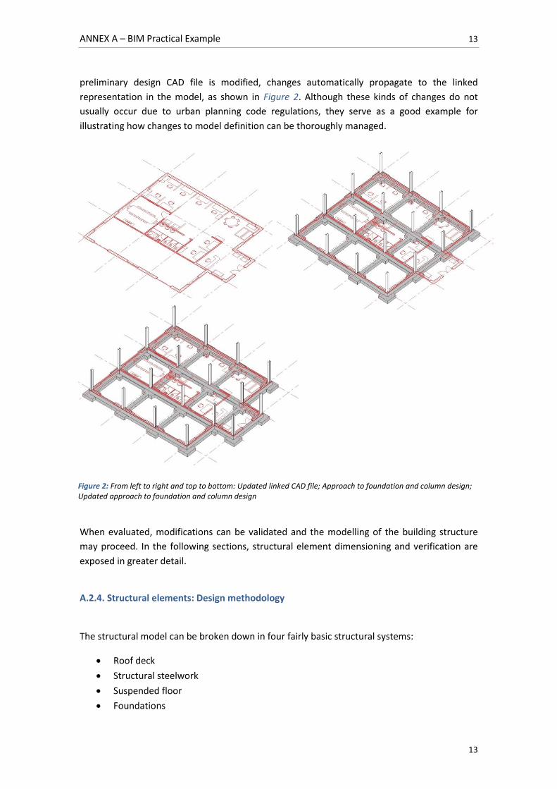
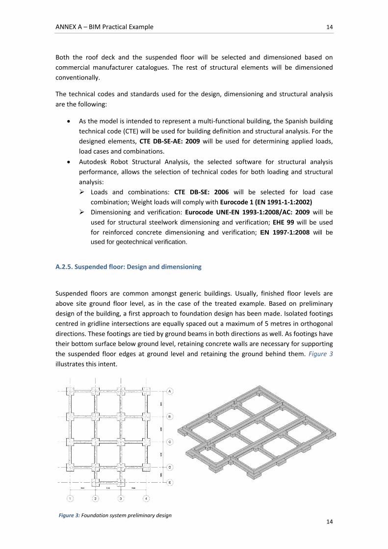
Suspended floors are common amongst generic buildings. Usually, finished floor levels are
above site ground floor level, as in the case of the treated example. Based on preliminary
design of the building, a first approach to foundation design has been made. Isolated footings
centred in gridline intersections are equally spaced out a maximum of 5 metres in orthogonal
directions. These footings are tied by ground beams in both directions as well. As footings have
their bottom surface below ground level, retaining concrete walls are necessary for supporting
the suspended floor edges at ground level and retaining the ground behind them. Figure 3
illustrates this intent.
Figure 3: Foundation system preliminary design
ANNEX A – BIM Practical Example 15
15
For constructability purposes, hollow-core precast concrete slabs will be used to materialise
the suspended floor. These slabs will span 5 metres from wall to wall. The slab section to be
used will be selected from a commercial manufacturer’s catalogue. The author has chosen
‘Prevalesa S.L.’ as supplier. All structural properties of hollow core section precast concrete
slabs are available in their product catalogue [14].
Load assignment
Applied loads comply with CTE DB-SE-AE: 2009 [6] and are as follows:
Dead Loads (DL):
Self-weight: Self weight is defined by the chosen precast hollow core concrete slab
section.
Internal walls: An assumed specific weight of 1.2 kN/m² for internal walls will be
applied. Based on the building’s predesign documents, there are 35 linear meters
of internal walls with an approximate height of 3 meters. This sums up to 126 kN
uniformly distributed within 15x15 m² according to CTE DB-SE-AE: 2009, resulting
in 0.56 KN/m².
Floor finishing layers: Based on preliminary architectural design, a 10mm PVC
layer will be used as floor finishing layer. An assumed specific weight of 0.14
kN/m² will be considered. Floor finish weight will not be taken into account for the
scope of an approached dimensioning.
Other additional dead loads are neglected for the scope of an approached
dimensioning.
Live Loads1 (LL):
Service overloads: As described in the building functionality and requirements,
service overloads better adapt to an administrative zone (B). This implies uniformly
distributed service overloads of 2 kN/m² with additional evacuation and access
overloads of 1 kN/m² resulting in maximum distributed overloads of 3 kN/m².
Point loads of 2 kN have to be considered additionally.
Thermal variations: The building’s structural elements have been designed with
lengths that do not surpass 40 m. Therefore, thermal variation actions can be
neglected.
Serviceability Limit State verification (SLS)
According to structural concrete code EHE-08 Art. 50.2.2.1, slab deformability must not be
verified if its thickness surpasses a given value [5]. This applies to hollow core pre-stressed
concrete slabs that span less than 12 meters and have overloads smaller than 4 kN/m².
1 As pointed in CTE DB-SE-AE 3.1.1.7, live loads already include alternate loading effects.
ANNEX A – BIM Practical Example 16
16
As the hollow core slabs for the suspended floor span 5 metres and have a maximum overload
of 3 kN/m², can be calculated as follows:
Total load:
√
⁄
Span:
C = 36 (From EHE-08 Table 50.2.2.1b – Hollow core pre-stressed slabs with walls)
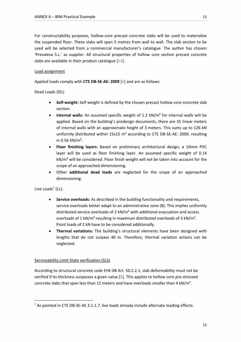
For a first approach, a preliminary section will be selected from the catalogue [14]. For
constructability purposes, sections with 1m of width will be chosen so that an integer number
of slabs are used (15m are covered with 15 slabs, for instance), avoiding unnecessary
trimming. Therefore, a first approach will be section PF15.XX from supplier’s catalogue, shown
in Figure 4.
Figure 4: Hollow core section slab PF15.XX cross section [14]
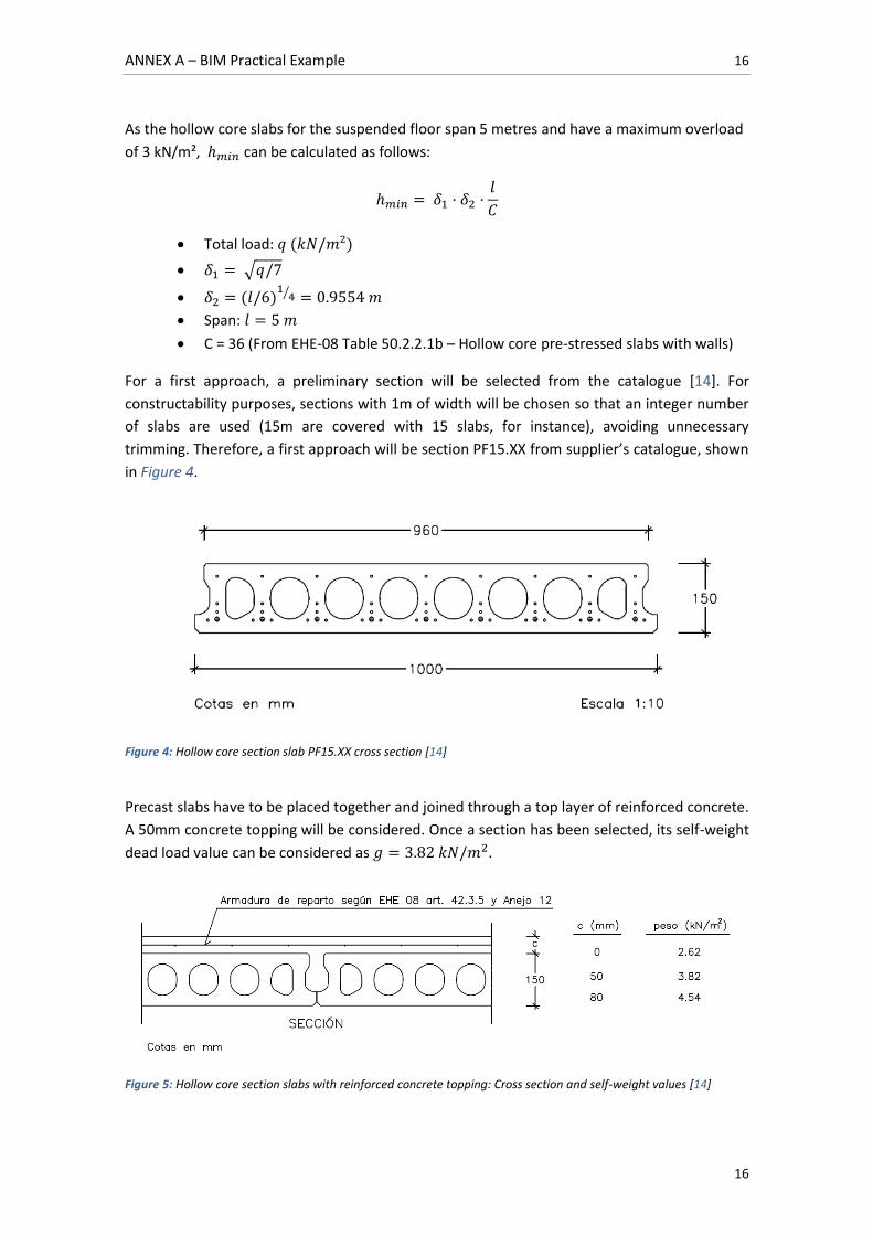
Precast slabs have to be placed together and joined through a top layer of reinforced concrete.
A 50mm concrete topping will be considered. Once a section has been selected, its self-weight
dead load value can be considered as .
Figure 5: Hollow core section slabs with reinforced concrete topping: Cross section and self-weight values [14]
ANNEX A – BIM Practical Example 17
17
Total loads can now be obtained: Minimum suspended
floor thickness results in . As section PF15.XX is thick, and it is
the smallest section in the catalogue, resistance verification can take place.
Ultimate Limit State verification (ULS):
The slabs span 5 meters and are simply supported at both ends. The considered load
combination will be persistent or transitory, neglecting other combinations:
Partial security factors are specified in CTE DB-SE Table 4.1 [8].
As there are two possible overloads, distributed and point overload, two forces will be
obtained and only the higher one will be selected for dimensioning.
Case 1 - Distributed overload:
As slabs are 1 meter wide, .
Maximum Bending Moment
Maximum Shear Strength
Case 2 - Point overload:
As slabs are 1.0 meter wide,
Maximum Bending Moment
Maximum Shear Strength
As appreciated, Case 1 is more demanding than Case 2.
ANNEX A – BIM Practical Example 18
18
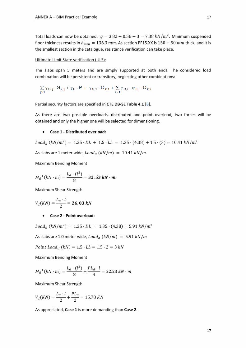
Referring back to the supplier’s catalogue, a precast hollow core section concrete slab can be
selected taking into consideration the chosen topping thickness. A PF 15.10 Slab with 50 mm
top reinforced concrete layer will be selected [14].
The resistance of the chosen suspended floor section will be verified as follows:
Bending Moment:
(
)
As the selected slab is 1 meter wide,
Resistance to bending moment is verified, as .
Shear Strength:
As for any given type of environmental exposition, at
. With 1 meter wide slabs, .
Shear strength resistance is verified, as .
A.2.6. Creation of a precast concrete slab parametric family
The selected section is the ‘DITECO PF15.10’, supplied by ‘Prevalesa S.L.’ [14]. As the slabs have
been already dimensioned and verified it is not necessary to include them in the project’s
analytical model2. Nevertheless, they are important elements of the building which have to be
represented in the physical model.
2 The analytical model is described in further detail in subsection A.2.9.
Table 2: Mechanical and strength resistance properties of hollow core section slab systems [14]
ANNEX A – BIM Practical Example 19
19
Several considerations have to be taken into account when creating a parametric object family.
Based on the foreseen uses of the component’s representation, key information from the
element has to be incorporated to the model. Precise geometry of the slab is necessary for
physical representation. This will allow for constructability verification and drawing generation
amongst other uses. Other basic physical properties such as material type and its appearance
are necessary for both quantity take-offs and rendering respectively. Further detailed
information such as material and execution cost attributes may be necessary for generating
cost estimates. Other information such as fire resistance and thermal conductivity for energy
analysis can be included. For the scope of this work, reinforcement elements will not be
modelled for the slabs, as they will not be included in the Analytical Model for structural
analysis and detailed rebar information is found in supplier’s catalogue.
Autodesk Revit allows the generation of object families from predefined parametric templates.
In this particular case, a hollow core section slab best fits with the parametric behaviour of
Revit’s framing beams. When selecting a beam family template, the beam profile can be
customized to whichever section is needed. Parametric properties can be also defined at will.
However, there are certain behaviour properties that are predefined. For instance, when
placing a beam in the model, it will automatically adapt to its nearest supports at both ends. It
will also have an automatic analytical representation in the analytical model, which will be
deactivated, as afore mentioned.
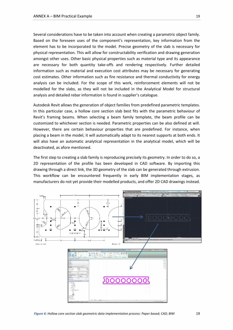
The first step to creating a slab family is reproducing precisely its geometry. In order to do so, a
2D representation of the profile has been developed in CAD software. By importing this
drawing through a direct link, the 3D geometry of the slab can be generated through extrusion.
This workflow can be encountered frequently in early BIM implementation stages, as
manufacturers do not yet provide their modelled products, and offer 2D CAD drawings instead.
Figure 6: Hollow core section slab geometric data implementation process: Paper based; CAD; BIM
ANNEX A – BIM Practical Example 20
20
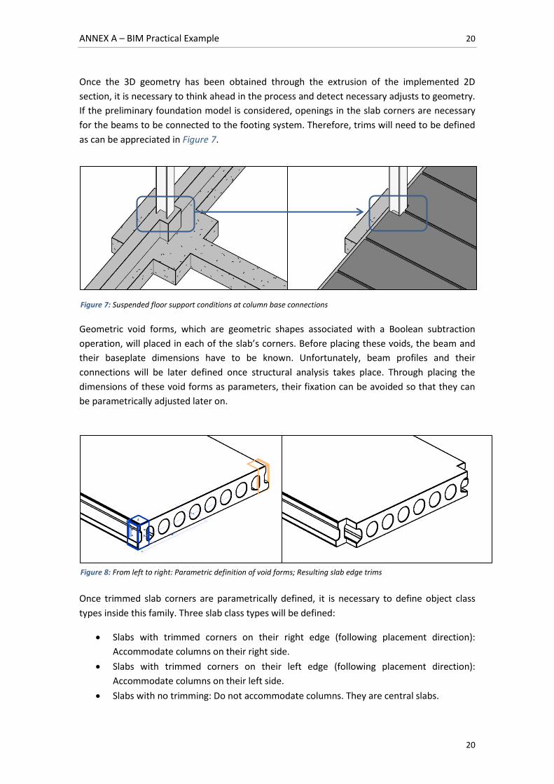
Once the 3D geometry has been obtained through the extrusion of the implemented 2D
section, it is necessary to think ahead in the process and detect necessary adjusts to geometry.
If the preliminary foundation model is considered, openings in the slab corners are necessary
for the beams to be connected to the footing system. Therefore, trims will need to be defined
as can be appreciated in Figure 7.
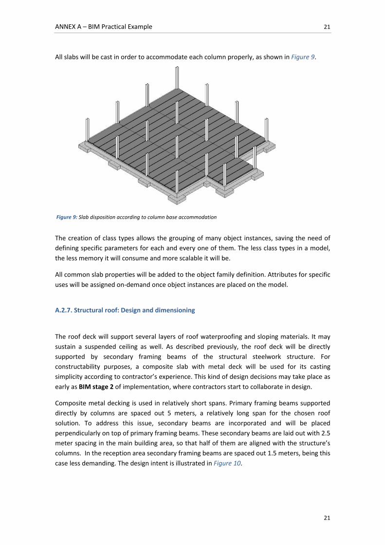
Geometric void forms, which are geometric shapes associated with a Boolean subtraction
operation, will placed in each of the slab’s corners. Before placing these voids, the beam and
their baseplate dimensions have to be known. Unfortunately, beam profiles and their
connections will be later defined once structural analysis takes place. Through placing the
dimensions of these void forms as parameters, their fixation can be avoided so that they can
be parametrically adjusted later on.
Once trimmed slab corners are parametrically defined, it is necessary to define object class
types inside this family. Three slab class types will be defined:
Slabs with trimmed corners on their right edge (following placement direction):
Accommodate columns on their right side.
Slabs with trimmed corners on their left edge (following placement direction):
Accommodate columns on their left side.
Slabs with no trimming: Do not accommodate columns. They are central slabs.
Figure 7: Suspended floor support conditions at column base connections
Figure 8: From left to right: Parametric definition of void forms; Resulting slab edge trims
ANNEX A – BIM Practical Example 21
21
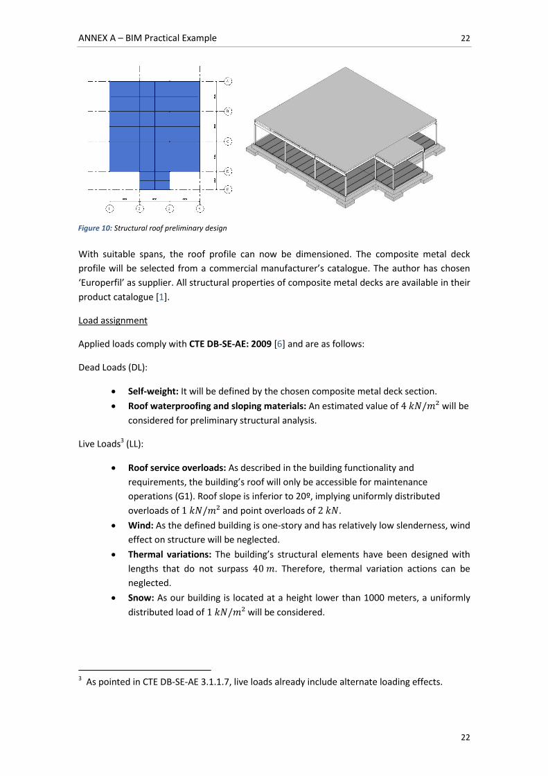
All slabs will be cast in order to accommodate each column properly, as shown in Figure 9.
The creation of class types allows the grouping of many object instances, saving the need of
defining specific parameters for each and every one of them. The less class types in a model,
the less memory it will consume and more scalable it will be.
All common slab properties will be added to the object family definition. Attributes for specific
uses will be assigned on-demand once object instances are placed on the model.
A.2.7. Structural roof: Design and dimensioning
The roof deck will support several layers of roof waterproofing and sloping materials. It may
sustain a suspended ceiling as well. As described previously, the roof deck will be directly
supported by secondary framing beams of the structural steelwork structure. For
constructability purposes, a composite slab with metal deck will be used for its casting
simplicity according to contractor’s experience. This kind of design decisions may take place as
early as BIM stage 2 of implementation, where contractors start to collaborate in design.
Composite metal decking is used in relatively short spans. Primary framing beams supported
directly by columns are spaced out 5 meters, a relatively long span for the chosen roof
solution. To address this issue, secondary beams are incorporated and will be placed
perpendicularly on top of primary framing beams. These secondary beams are laid out with 2.5
meter spacing in the main building area, so that half of them are aligned with the structure’s
columns. In the reception area secondary framing beams are spaced out 1.5 meters, being this
case less demanding. The design intent is illustrated in Figure 10.
Figure 9: Slab disposition according to column base accommodation
ANNEX A – BIM Practical Example 22
22
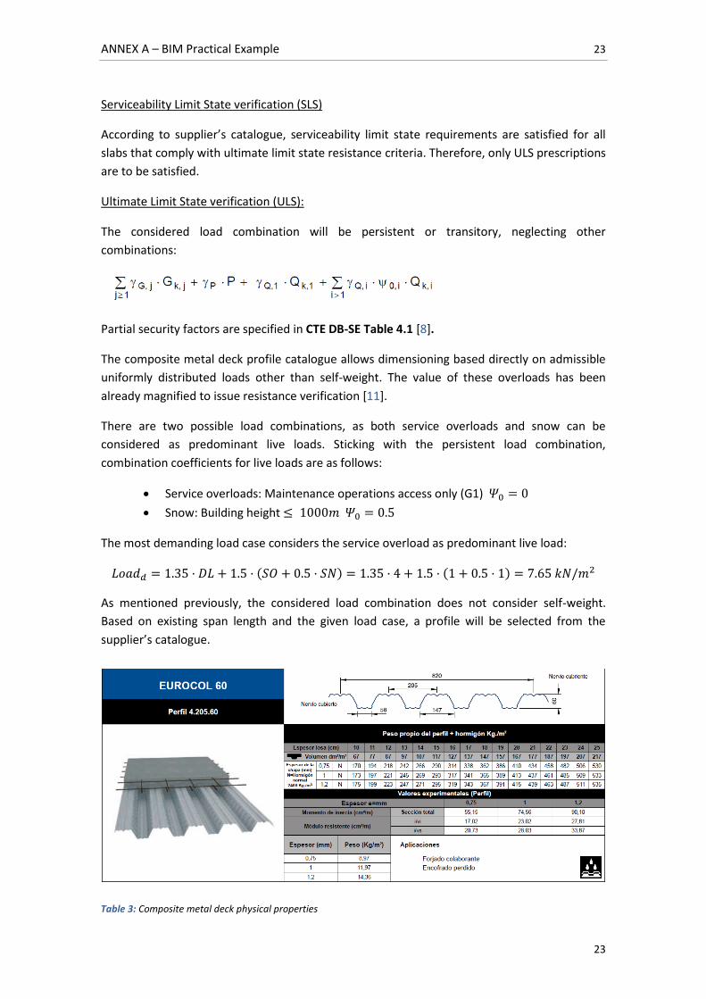
With suitable spans, the roof profile can now be dimensioned. The composite metal deck
profile will be selected from a commercial manufacturer’s catalogue. The author has chosen
‘Europerfil’ as supplier. All structural properties of composite metal decks are available in their
product catalogue [1].
Load assignment
Applied loads comply with CTE DB-SE-AE: 2009 [6] and are as follows:
Dead Loads (DL):
Self-weight: It will be defined by the chosen composite metal deck section.
Roof waterproofing and sloping materials: An estimated value of will be
considered for preliminary structural analysis.
Live Loads3 (LL):
Roof service overloads: As described in the building functionality and
requirements, the building’s roof will only be accessible for maintenance
operations (G1). Roof slope is inferior to 20º, implying uniformly distributed
overloads of and point overloads of .
Wind: As the defined building is one-story and has relatively low slenderness, wind
effect on structure will be neglected.
Thermal variations: The building’s structural elements have been designed with
lengths that do not surpass . Therefore, thermal variation actions can be
neglected.
Snow: As our building is located at a height lower than 1000 meters, a uniformly
distributed load of will be considered.
3 As pointed in CTE DB-SE-AE 3.1.1.7, live loads already include alternate loading effects.
Figure 10: Structural roof preliminary design
ANNEX A – BIM Practical Example 23
23
Serviceability Limit State verification (SLS)
According to supplier’s catalogue, serviceability limit state requirements are satisfied for all
slabs that comply with ultimate limit state resistance criteria. Therefore, only ULS prescriptions
are to be satisfied.
Ultimate Limit State verification (ULS):
The considered load combination will be persistent or transitory, neglecting other
combinations:
Partial security factors are specified in CTE DB-SE Table 4.1 [8].
The composite metal deck profile catalogue allows dimensioning based directly on admissible
uniformly distributed loads other than self-weight. The value of these overloads has been
already magnified to issue resistance verification [11].
There are two possible load combinations, as both service overloads and snow can be
considered as predominant live loads. Sticking with the persistent load combination,
combination coefficients for live loads are as follows:
Service overloads: Maintenance operations access only (G1)
Snow: Building height
The most demanding load case considers the service overload as predominant live load:
As mentioned previously, the considered load combination does not consider self-weight.
Based on existing span length and the given load case, a profile will be selected from the
supplier’s catalogue.
Table 3: Composite metal deck physical properties
ANNEX A – BIM Practical Example 24
24
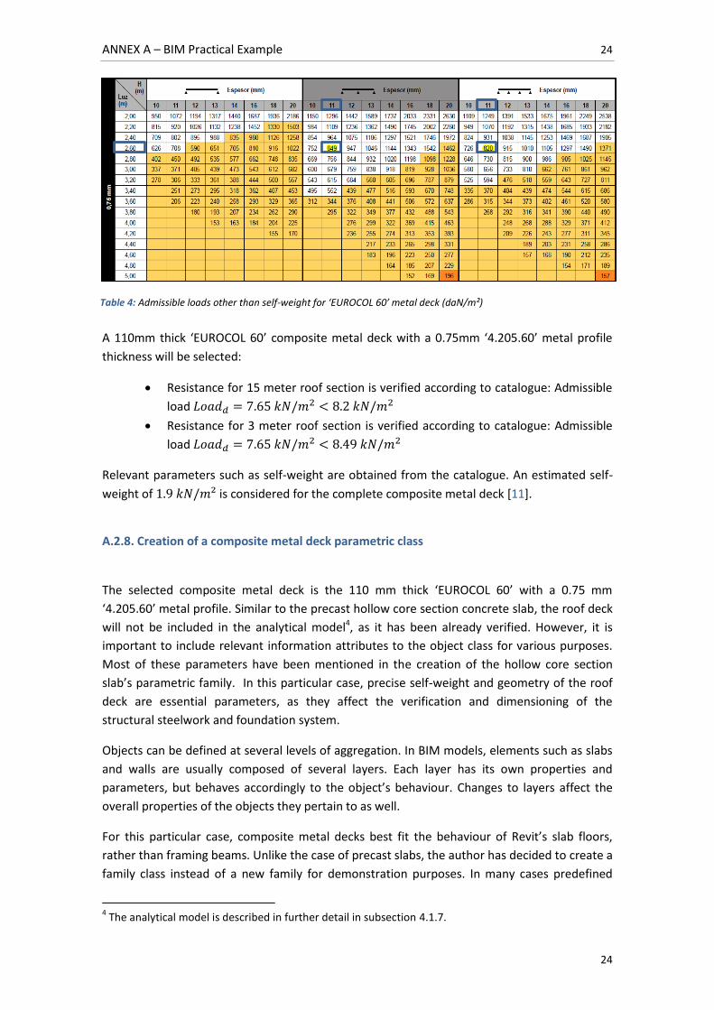
A 110mm thick ‘EUROCOL 60’ composite metal deck with a 0.75mm ‘4.205.60’ metal profile
thickness will be selected:
Resistance for 15 meter roof section is verified according to catalogue: Admissible
load
Resistance for 3 meter roof section is verified according to catalogue: Admissible
load
Relevant parameters such as self-weight are obtained from the catalogue. An estimated self-
weight of is considered for the complete composite metal deck [11].
A.2.8. Creation of a composite metal deck parametric class
The selected composite metal deck is the 110 mm thick ‘EUROCOL 60’ with a 0.75 mm
‘4.205.60’ metal profile. Similar to the precast hollow core section concrete slab, the roof deck
will not be included in the analytical model4, as it has been already verified. However, it is
important to include relevant information attributes to the object class for various purposes.
Most of these parameters have been mentioned in the creation of the hollow core section
slab’s parametric family. In this particular case, precise self-weight and geometry of the roof
deck are essential parameters, as they affect the verification and dimensioning of the
structural steelwork and foundation system.
Objects can be defined at several levels of aggregation. In BIM models, elements such as slabs
and walls are usually composed of several layers. Each layer has its own properties and
parameters, but behaves accordingly to the object’s behaviour. Changes to layers affect the
overall properties of the objects they pertain to as well.
For this particular case, composite metal decks best fit the behaviour of Revit’s slab floors,
rather than framing beams. Unlike the case of precast slabs, the author has decided to create a
family class instead of a new family for demonstration purposes. In many cases predefined
4 The analytical model is described in further detail in subsection 4.1.7.
Table 4: Admissible loads other than self-weight for ‘EUROCOL 60’ metal deck (daN/m²)
ANNEX A – BIM Practical Example 25
25
object families in BIM platforms are appropriate enough for the creation of customised classes
inside that particular family. As composite metal decks share the same basic purposes in the
AEC industry as concrete slabs, and have several shared parameters, they can be included in a
cast-in-place concrete slab floor generic family. Nevertheless, it is up to the BIM users to
decide whether to create a whole new family or an object class inside another family. This
criterion responds to both constructability and structural design considerations for structural
components.
The composite metal deck will be created as a class inside a predefined floor family. For a first
approach, a duplicate of a ‘generic 300’ concrete floor slab class will be generated for
customisation. Once duplicated, the class can be re-named and have its properties modified.
The class will be re-named to ‘Composite metal deck 110mm/0.75mm’ as a floor class, and its
layers will be customized. Two basic layers can be obviously distinguished in the roof deck:
Reinforced concrete and the metal profile. The concrete layer already exists in the duplicated
class, but the metal profile still has to be implemented.
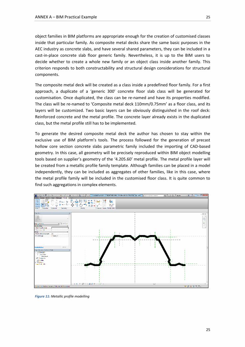
To generate the desired composite metal deck the author has chosen to stay within the
exclusive use of BIM platform’s tools. The process followed for the generation of precast
hollow core section concrete slabs parametric family included the importing of CAD-based
geometry. In this case, all geometry will be precisely reproduced within BIM object modelling
tools based on supplier’s geometry of the ‘4.205.60’ metal profile. The metal profile layer will
be created from a metallic profile family template. Although families can be placed in a model
independently, they can be included as aggregates of other families, like in this case, where
the metal profile family will be included in the customised floor class. It is quite common to
find such aggregations in complex elements.
Figure 11: Metallic profile modelling
ANNEX A – BIM Practical Example 26
26
Figure 11 shows how profiles can be modelled and defined. Only unit geometry has to be
drawn, as it will be mirrored as many times as necessary to fit the desired width. Information
regarding manufacturer, profile model, supplier URL, cost and many more can be included in
the profile family properties.
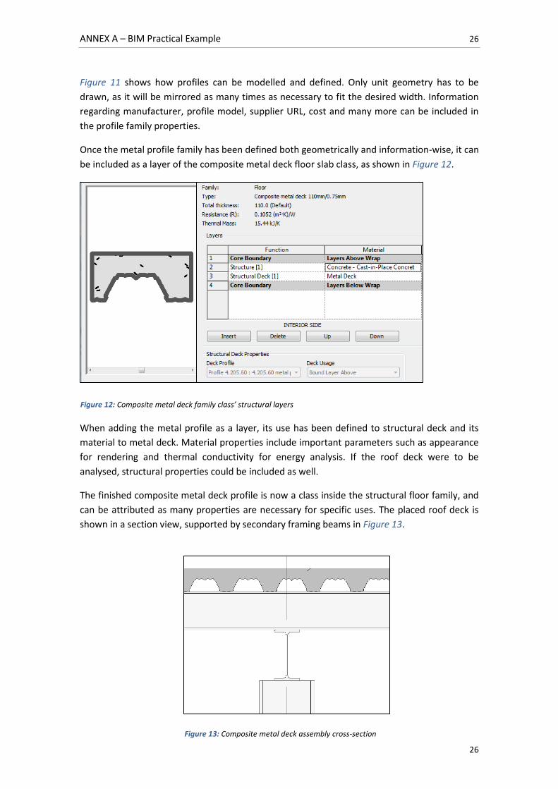
Once the metal profile family has been defined both geometrically and information-wise, it can
be included as a layer of the composite metal deck floor slab class, as shown in Figure 12.
When adding the metal profile as a layer, its use has been defined to structural deck and its
material to metal deck. Material properties include important parameters such as appearance
for rendering and thermal conductivity for energy analysis. If the roof deck were to be
analysed, structural properties could be included as well.
The finished composite metal deck profile is now a class inside the structural floor family, and
can be attributed as many properties are necessary for specific uses. The placed roof deck is
shown in a section view, supported by secondary framing beams in Figure 13.
Figure 12: Composite metal deck family class’ structural layers
Figure 13: Composite metal deck assembly cross-section
ANNEX A – BIM Practical Example 27
27
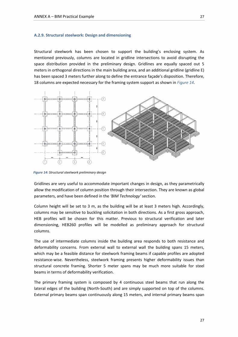
A.2.9. Structural steelwork: Design and dimensioning
Structural steelwork has been chosen to support the building’s enclosing system. As
mentioned previously, columns are located in gridline intersections to avoid disrupting the
space distribution provided in the preliminary design. Gridlines are equally spaced out 5
meters in orthogonal directions in the main building area, and an additional gridline (gridline E)
has been spaced 3 meters further along to define the entrance façade’s disposition. Therefore,
18 columns are expected necessary for the framing system support as shown in Figure 14.
Gridlines are very useful to accommodate important changes in design, as they parametrically
allow the modification of column position through their intersection. They are known as global
parameters, and have been defined in the ‘BIM Technology’ section.
Column height will be set to 3 m, as the building will be at least 3 meters high. Accordingly,
columns may be sensitive to buckling solicitation in both directions. As a first gross approach,
HEB profiles will be chosen for this matter. Previous to structural verification and later
dimensioning, HEB260 profiles will be modelled as preliminary approach for structural
columns.
The use of intermediate columns inside the building area responds to both resistance and
deformability concerns. From external wall to external wall the building spans 15 meters,
which may be a feasible distance for steelwork framing beams if capable profiles are adopted
resistance-wise. Nevertheless, steelwork framing presents higher deformability issues than
structural concrete framing. Shorter 5 meter spans may be much more suitable for steel
beams in terms of deformability verification.
The primary framing system is composed by 4 continuous steel beams that run along the
lateral edges of the building (North-South) and are simply supported on top of the columns.
External primary beams span continuously along 15 meters, and internal primary beams span
Figure 14: Structural steelwork preliminary design
ANNEX A – BIM Practical Example 28
28
continuously along 18 meters to cover the reception area. Beams will run continuously so that
they perform efficiently. For a preliminary approach, IPE 240 beams will be used.
Secondary beams will run perpendicularly to the primary framing system. In the main building
area, 7 secondary beams will be laid out with 2.5 meter spacing, so that 4 of them are placed
in line with structural columns. In the reception area, 2 secondary framing beams will be
spaced out 1.5 meters. Except for the 5 meter beams in the reception area, all secondary
framing will continuously run along 15 meters from building edge to edge. For a preliminary
approach, IPE 180 beams will be used.
Roof loads will be directly applied to the secondary framing system, which will transmit them
to the primary framing system which in turn is supported by structural columns. Connections
between structural elements will be defined as dimensioning proceeds. The design intent is
illustrated in Figure 14.
Structural analysis tools
Once the structural system has been conceptualised, a pre-analysis structural model can be
developed. This model will include all necessary information for the dimensioning and
verification of the structural steelwork system.
Autodesk Revit has an integrated interface with Autodesk Robot Structural Analysis (RSA). RSA
is a powerful structural analysis tool, and it will be used to dimension and verify the treated
model. As both software titles belong to Autodesk, there is an established bi-directional
interoperability between Revit and RSA [2]. This is what has been defined as direct link in the
‘Interoperability’ section. These types of links allow complete structural analysis workflows
from the BIM model to the structural analysis software and from the analysis software back to
the model. Several sending options are available to select or filter interchanged information.
Once the model data has been interchanged, analysis can be performed. Results and
subsequent changes to the initial structural model can then be imported back to the Revit
platform with certain ease.
When using Revit as a BIM platform, structural analysis relies in outsider specific software. For
the purpose of this work, RSA has been used for its bi-directional interoperability features, but
analytical structural model data can also be exported to other analysis software as well. For
instance, the Tekla structures analytical software title could have been used for the same
purposes. In that case, results and modifications would have been more difficult to import or
would even have to be introduced by hand by the designer, as the lack of direct links
jeopardise advanced interoperability features. However, not all analyses depend on external
software. Other analyses such as Revit’s Energetic Analysis, are built inside the Revit platform
and can be executed directly on it (or through cloud services).
The analytical model
In order to perform structural analysis, a series of relevant information has to be gathered in
what has been called information sets or model views. As described in the ‘Interoperability’
section, model views are a subset of information of the whole BIM model destined for a
ANNEX A – BIM Practical Example 29
29
specific use or workflow. In this particular case, a structural BIM model of the treated building
has been developed, and all necessary information will have to be selected or defined for its
interchange.
The exported information from Revit to structural analysis software corresponds to what is
known as the analytical model. This view of the model includes structural elements and their
properties only, representing the structural system ideally. Geometry of the structural system
is defined in the analytical model in a basic way: Framing and columns are represented as
lines, walls and slabs are represented by their central plain and foundations are represented by
points. Loads, boundary conditions and connections between elements are also represented in
a simple way in this model view.
There is not a strict associativity between the physical model and the analytical model. Beam
connections are represented by points in space and beams by their centreline. If a secondary
framing beam is located on top of a primary beam which supports it, beam centrelines in the
analytical model will be placed at the same level for analysis because load is transmitted from
secondary to primary beams. Still, once changes due to structural dimensioning results are
imported back to Revit, the physical model can then reflect real positioning of elements for
desired constructive purposes. Even though these dissociative functionalities may be useful,
there are certain defined geometric tolerances between physical and analytical models which
ensure that the latter one is representative of the first one. This function is known as
‘Analytical/Physical Model Consistency Check’ in the Revit interface.
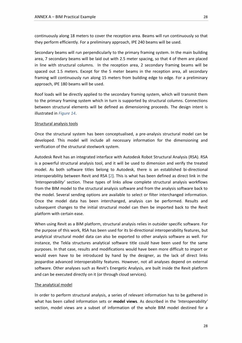
Figure 15 illustrates the analytical representation of the steelwork structure superposed to
their physical representation. As appreciated, there are colour codes that distinguish central
frame sections from end sections.
Figure 15: Analytical model of structural steelwork; Details with superposed physical model
ANNEX A – BIM Practical Example 30
30
Most of the relevant structural parameters are bi-directionally linked between Revit and RSA.
This means that not all necessary information for analysis has to be defined in Revit, but can
also be assigned in the RSA interface. For instance, if a structural engineer does not find a
desired beam profile in Revit, he can export the model to RSA and find it in a more specialised
profile library.
To illustrate this, and based on the recommendations of Autodesk’s guide to Revit-RSA direct
link [2], only some basic information will be defined in Revit to be later completed in RSA:
Structural system geometry has been already defined in the Revit model
Beam profiles will be modelled in Revit
Boundary conditions will be defined for columns as fixed at their base
Load cases and combinations will be defined in RSA and assigned directly on its interface.
Other properties and elements such as material classes and steelwork connections will be
directly dimensioned and verified in RSA. As these properties are bi-directional, they will be
imported to the Revit model.
For the purpose of this work only structural steelwork will be sent to RSA for structural
analysis. Suspended floor and composite metal decks have been previously verified. Therefore,
they will not be included in the Analytical Model.
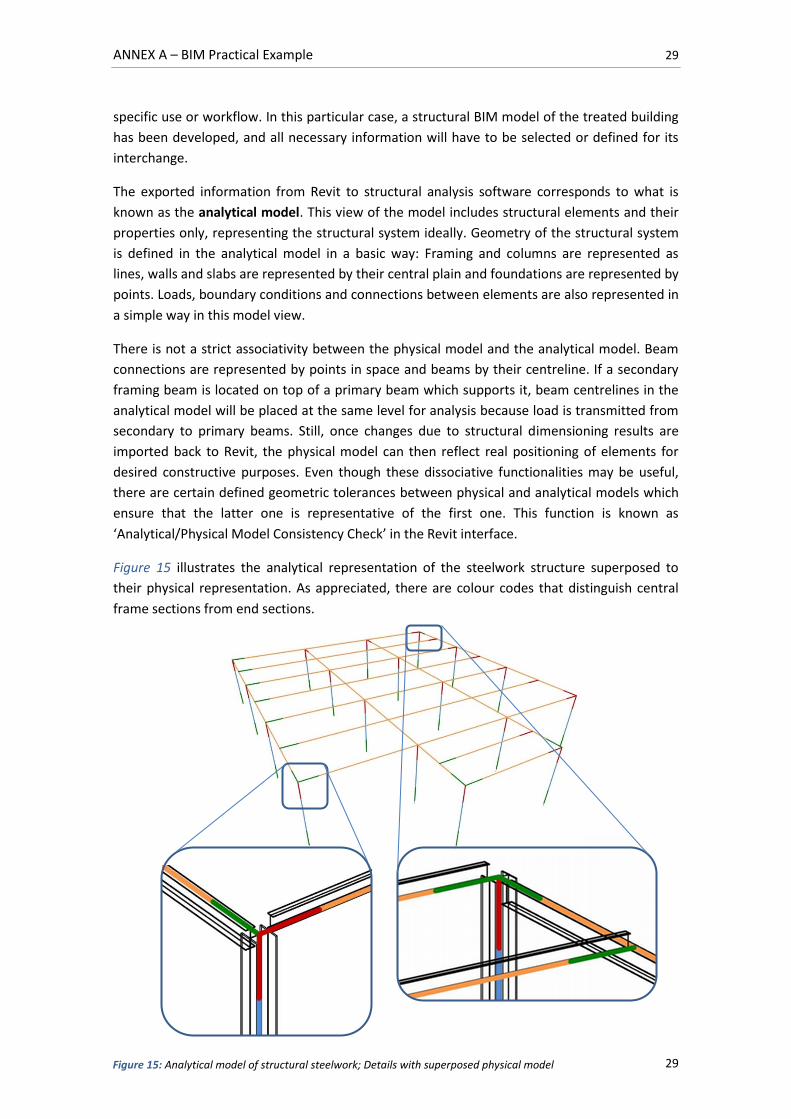
Figure 16 shows the defined Analytical Model in Revit and its exported representation in RSA.
As appreciated, RSA has imported specified geometric, profile and boundary condition
information.
Figure 16: From left to right: Analytical model defined in Revit; Analytical model exported to RSA
ANNEX A – BIM Practical Example 31
31
Load assignment
Applied loads comply with CTE DB-SE-AE: 2009 [6] and are as follows:
Dead Loads (DL):
Self-weight: It will be defined by the chosen steel profiles.
Composite metal decking: The chosen 110mm thick composite metal deck weights
according to supplier’s catalogue [11].
Roof waterproofing and sloping materials: An estimated value of will be
considered for preliminary structural analysis.
Live Loads5 (LL):
Roof service overloads: As described in the building functionality and requirements,
the building’s roof will only be accessible for maintenance operations (G1). Roof slope
is inferior to 20º, implying uniformly distributed overloads of and point
overloads of .
Wind: As the defined building is one-story and has relatively low slenderness, wind
effect on structure will be neglected.
Thermal variations: The building’s structural elements have been designed with
lengths that do not surpass . Therefore, thermal variation actions can be
neglected.
Snow: As our building is located at a height lower than 1000 meters, a uniformly
distributed load of will be considered.
Load cases defined in RSA are as follows:
DL1: Self weight
DL2: Roof waterproofing, sloping materials and composite metal decking weight
LL1: Service overload
LL2: Snow
The followed codes and standards used by Autodesk Robot Structural Analysis are specified in
subsection 4.1.2.
Load application
Apart from self-weight, loads will be directly applied to each element in the secondary framing
system, as the roof is directly supported on it. As loads are uniformly distributed on the roof,
each secondary beam will be assigned its corresponding supported width. Therefore, central
secondary beams will support higher loads than those located in the building’s edges. Due to
the slight magnitude of service point overloads and the load distribution effect in the treated
structural system, point load analysis will be neglected.
5 As pointed in CTE DB-SE-AE 3.1.1.7, live loads already include alternate loading effects.
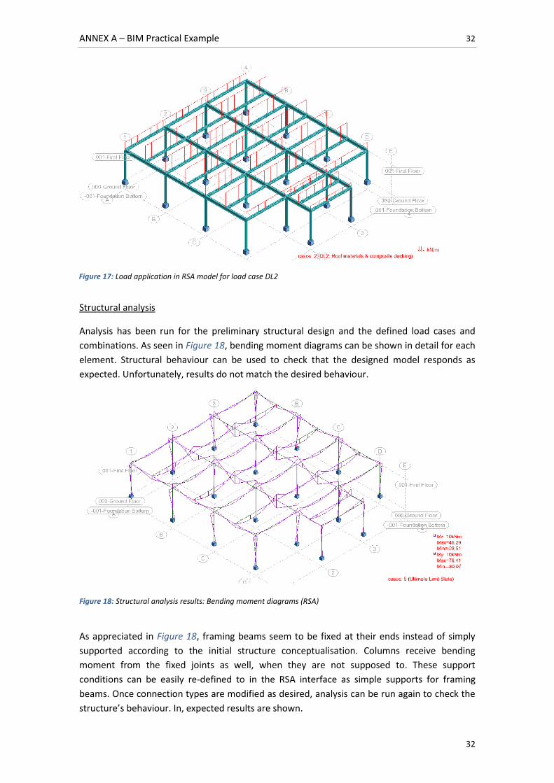
ANNEX A – BIM Practical Example 32
32
Structural analysis
Analysis has been run for the preliminary structural design and the defined load cases and
combinations. As seen in Figure 18, bending moment diagrams can be shown in detail for each
element. Structural behaviour can be used to check that the designed model responds as
expected. Unfortunately, results do not match the desired behaviour.
Figure 18: Structural analysis results: Bending moment diagrams (RSA)
As appreciated in Figure 18, framing beams seem to be fixed at their ends instead of simply
supported according to the initial structure conceptualisation. Columns receive bending
moment from the fixed joints as well, when they are not supposed to. These support
conditions can be easily re-defined to in the RSA interface as simple supports for framing
beams. Once connection types are modified as desired, analysis can be run again to check the
structure’s behaviour. In, expected results are shown.
Figure 17: Load application in RSA model for load case DL2
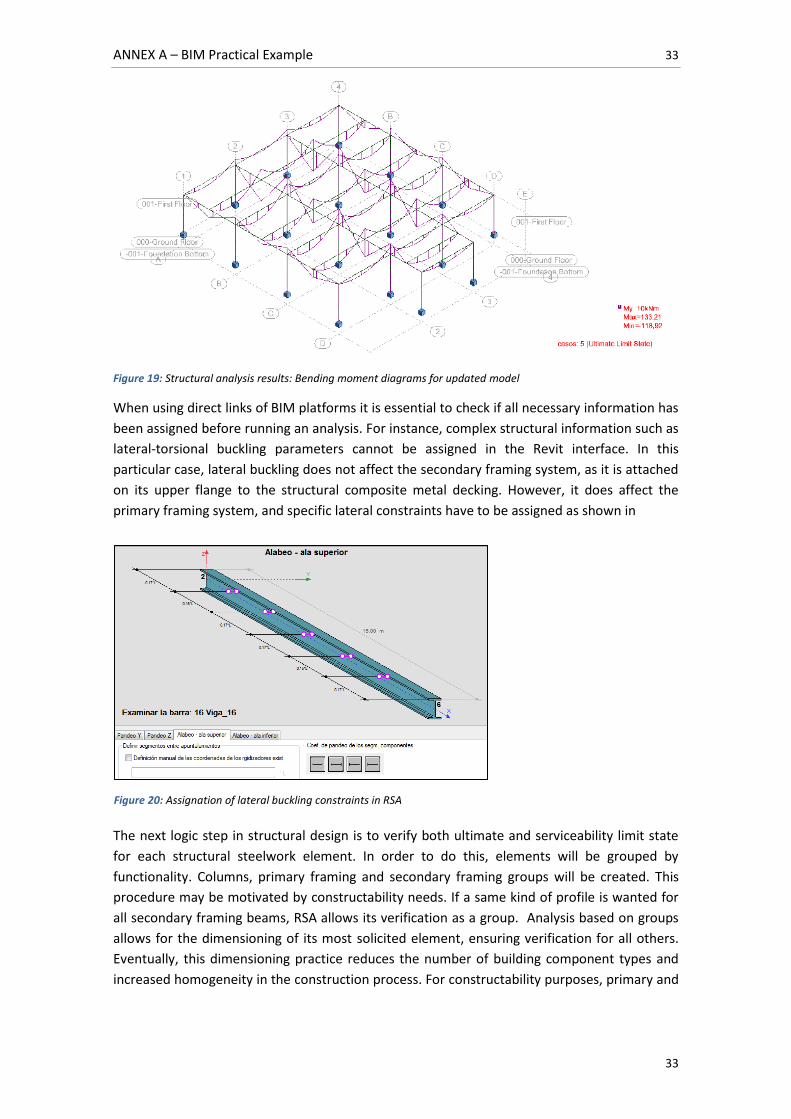
ANNEX A – BIM Practical Example 33
33
Figure 19: Structural analysis results: Bending moment diagrams for updated model
When using direct links of BIM platforms it is essential to check if all necessary information has
been assigned before running an analysis. For instance, complex structural information such as
lateral-torsional buckling parameters cannot be assigned in the Revit interface. In this
particular case, lateral buckling does not affect the secondary framing system, as it is attached
on its upper flange to the structural composite metal decking. However, it does affect the
primary framing system, and specific lateral constraints have to be assigned as shown in
The next logic step in structural design is to verify both ultimate and serviceability limit state
for each structural steelwork element. In order to do this, elements will be grouped by
functionality. Columns, primary framing and secondary framing groups will be created. This
procedure may be motivated by constructability needs. If a same kind of profile is wanted for
all secondary framing beams, RSA allows its verification as a group. Analysis based on groups
allows for the dimensioning of its most solicited element, ensuring verification for all others.
Eventually, this dimensioning practice reduces the number of building component types and
increased homogeneity in the construction process. For constructability purposes, primary and
Figure 20: Assignation of lateral buckling constraints in RSA
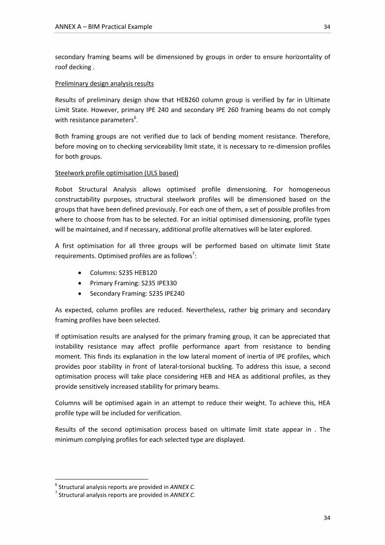
ANNEX A – BIM Practical Example 34
34
secondary framing beams will be dimensioned by groups in order to ensure horizontality of
roof decking .
Preliminary design analysis results
Results of preliminary design show that HEB260 column group is verified by far in Ultimate
Limit State. However, primary IPE 240 and secondary IPE 260 framing beams do not comply
with resistance parameters6.
Both framing groups are not verified due to lack of bending moment resistance. Therefore,
before moving on to checking serviceability limit state, it is necessary to re-dimension profiles
for both groups.
Steelwork profile optimisation (ULS based)
Robot Structural Analysis allows optimised profile dimensioning. For homogeneous
constructability purposes, structural steelwork profiles will be dimensioned based on the
groups that have been defined previously. For each one of them, a set of possible profiles from
where to choose from has to be selected. For an initial optimised dimensioning, profile types
will be maintained, and if necessary, additional profile alternatives will be later explored.
A first optimisation for all three groups will be performed based on ultimate limit State
requirements. Optimised profiles are as follows7:
Columns: S235 HEB120
Primary Framing: S235 IPE330
Secondary Framing: S235 IPE240
As expected, column profiles are reduced. Nevertheless, rather big primary and secondary
framing profiles have been selected.
If optimisation results are analysed for the primary framing group, it can be appreciated that
instability resistance may affect profile performance apart from resistance to bending
moment. This finds its explanation in the low lateral moment of inertia of IPE profiles, which
provides poor stability in front of lateral-torsional buckling. To address this issue, a second
optimisation process will take place considering HEB and HEA as additional profiles, as they
provide sensitively increased stability for primary beams.
Columns will be optimised again in an attempt to reduce their weight. To achieve this, HEA
profile type will be included for verification.
Results of the second optimisation process based on ultimate limit state appear in . The
minimum complying profiles for each selected type are displayed.
6 Structural analysis reports are provided in ANNEX C.
7 Structural analysis reports are provided in ANNEX C.
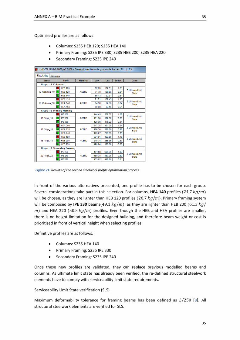
ANNEX A – BIM Practical Example 35
35
Optimised profiles are as follows:
Columns: S235 HEB 120; S235 HEA 140
Primary Framing: S235 IPE 330; S235 HEB 200; S235 HEA 220
Secondary Framing: S235 IPE 240
In front of the various alternatives presented, one profile has to be chosen for each group.
Several considerations take part in this selection. For columns, HEA 140 profiles
will be chosen, as they are lighter than HEB 120 profiles . Primary framing system
will be composed by IPE 330 beams , as they are lighter than HEB 200
and HEA 220 profiles. Even though the HEB and HEA profiles are smaller,
there is no height limitation for the designed building, and therefore beam weight or cost is
prioritised in front of vertical height when selecting profiles.
Definitive profiles are as follows:
Columns: S235 HEA 140
Primary Framing: S235 IPE 330
Secondary Framing: S235 IPE 240
Once these new profiles are validated, they can replace previous modelled beams and
columns. As ultimate limit state has already been verified, the re-defined structural steelwork
elements have to comply with serviceability limit state requirements.
Serviceability Limit State verification (SLS)
Maximum deformability tolerance for framing beams has been defined as [8]. All
structural steelwork elements are verified for SLS.
Figure 21: Results of the second steelwork profile optimisation process
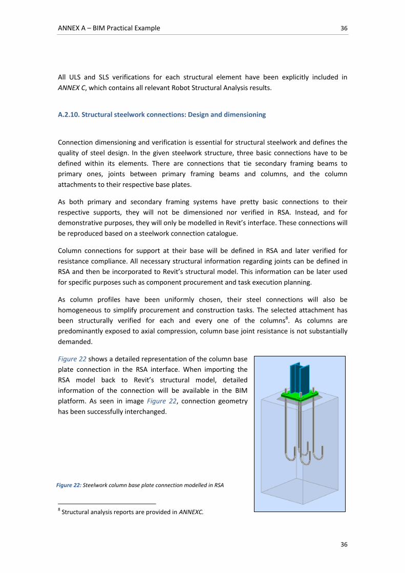
ANNEX A – BIM Practical Example 36
36
All ULS and SLS verifications for each structural element have been explicitly included in
ANNEX C, which contains all relevant Robot Structural Analysis results.
A.2.10. Structural steelwork connections: Design and dimensioning
Connection dimensioning and verification is essential for structural steelwork and defines the
quality of steel design. In the given steelwork structure, three basic connections have to be
defined within its elements. There are connections that tie secondary framing beams to
primary ones, joints between primary framing beams and columns, and the column
attachments to their respective base plates.
As both primary and secondary framing systems have pretty basic connections to their
respective supports, they will not be dimensioned nor verified in RSA. Instead, and for
demonstrative purposes, they will only be modelled in Revit’s interface. These connections will
be reproduced based on a steelwork connection catalogue.
Column connections for support at their base will be defined in RSA and later verified for
resistance compliance. All necessary structural information regarding joints can be defined in
RSA and then be incorporated to Revit’s structural model. This information can be later used
for specific purposes such as component procurement and task execution planning.
As column profiles have been uniformly chosen, their steel connections will also be
homogeneous to simplify procurement and construction tasks. The selected attachment has
been structurally verified for each and every one of the columns8. As columns are
predominantly exposed to axial compression, column base joint resistance is not substantially
demanded.
Figure 22 shows a detailed representation of the column base
plate connection in the RSA interface. When importing the
RSA model back to Revit’s structural model, detailed
information of the connection will be available in the BIM
platform. As seen in image Figure 22, connection geometry
has been successfully interchanged.
8 Structural analysis reports are provided in ANNEXC.
Figure 22: Steelwork column base plate connection modelled in RSA
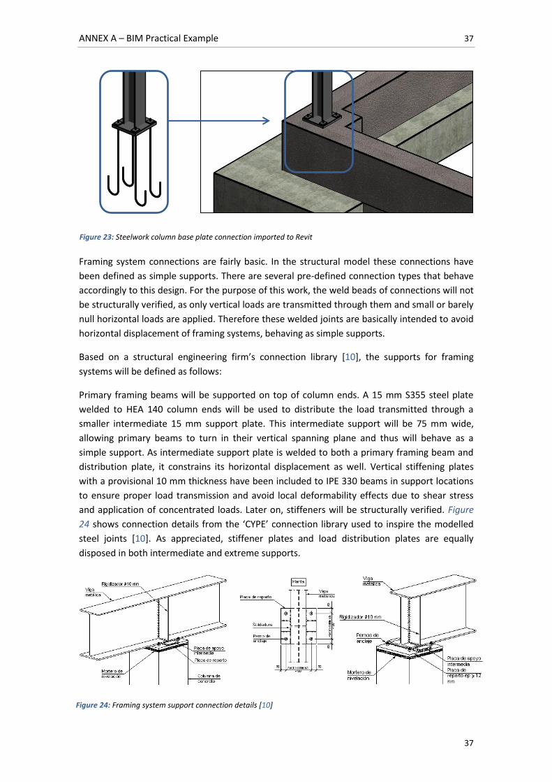
ANNEX A – BIM Practical Example 37
37
Framing system connections are fairly basic. In the structural model these connections have
been defined as simple supports. There are several pre-defined connection types that behave
accordingly to this design. For the purpose of this work, the weld beads of connections will not
be structurally verified, as only vertical loads are transmitted through them and small or barely
null horizontal loads are applied. Therefore these welded joints are basically intended to avoid
horizontal displacement of framing systems, behaving as simple supports.
Based on a structural engineering firm’s connection library [10], the supports for framing
systems will be defined as follows:
Primary framing beams will be supported on top of column ends. A 15 mm S355 steel plate
welded to HEA 140 column ends will be used to distribute the load transmitted through a
smaller intermediate 15 mm support plate. This intermediate support will be 75 mm wide,
allowing primary beams to turn in their vertical spanning plane and thus will behave as a
simple support. As intermediate support plate is welded to both a primary framing beam and
distribution plate, it constrains its horizontal displacement as well. Vertical stiffening plates
with a provisional 10 mm thickness have been included to IPE 330 beams in support locations
to ensure proper load transmission and avoid local deformability effects due to shear stress
and application of concentrated loads. Later on, stiffeners will be structurally verified. Figure
24 shows connection details from the ‘CYPE’ connection library used to inspire the modelled
steel joints [10]. As appreciated, stiffener plates and load distribution plates are equally
disposed in both intermediate and extreme supports.
Figure 23: Steelwork column base plate connection imported to Revit
Figure 24: Framing system support connection details [10]
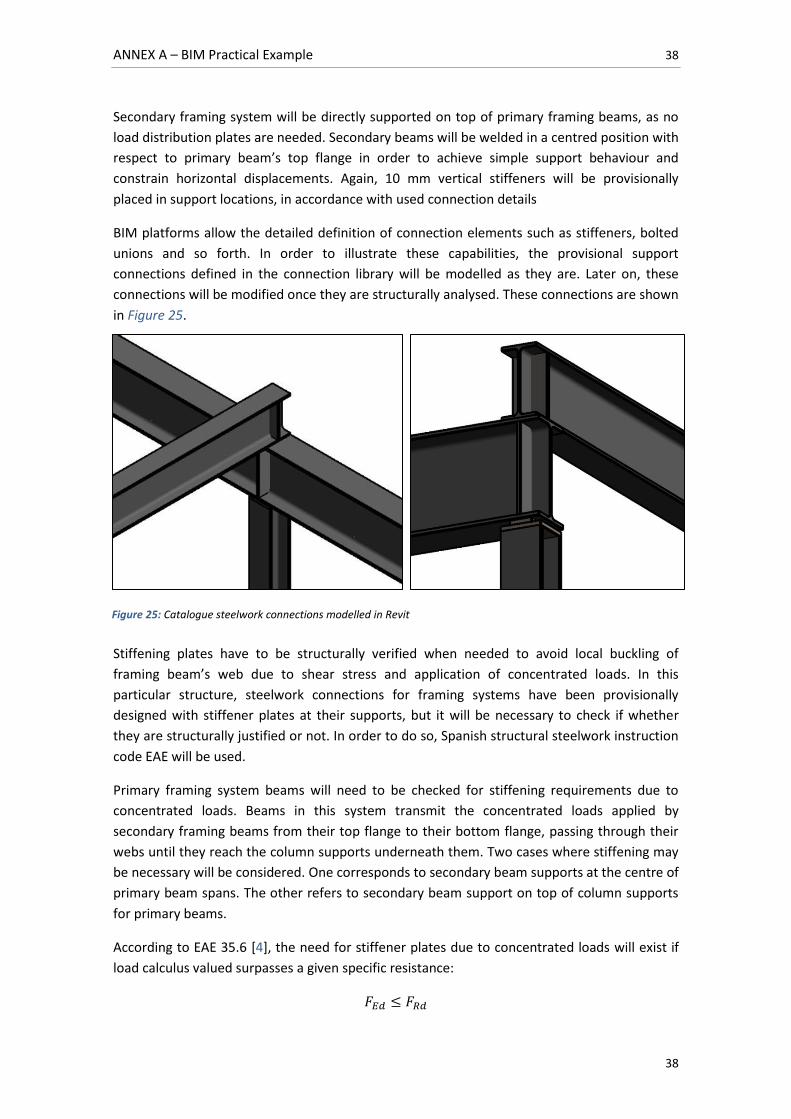
ANNEX A – BIM Practical Example 38
38
Secondary framing system will be directly supported on top of primary framing beams, as no
load distribution plates are needed. Secondary beams will be welded in a centred position with
respect to primary beam’s top flange in order to achieve simple support behaviour and
constrain horizontal displacements. Again, 10 mm vertical stiffeners will be provisionally
placed in support locations, in accordance with used connection details
BIM platforms allow the detailed definition of connection elements such as stiffeners, bolted
unions and so forth. In order to illustrate these capabilities, the provisional support
connections defined in the connection library will be modelled as they are. Later on, these
connections will be modified once they are structurally analysed. These connections are shown
in Figure 25.
Stiffening plates have to be structurally verified when needed to avoid local buckling of
framing beam’s web due to shear stress and application of concentrated loads. In this
particular structure, steelwork connections for framing systems have been provisionally
designed with stiffener plates at their supports, but it will be necessary to check if whether
they are structurally justified or not. In order to do so, Spanish structural steelwork instruction
code EAE will be used.
Primary framing system beams will need to be checked for stiffening requirements due to
concentrated loads. Beams in this system transmit the concentrated loads applied by
secondary framing beams from their top flange to their bottom flange, passing through their
webs until they reach the column supports underneath them. Two cases where stiffening may
be necessary will be considered. One corresponds to secondary beam supports at the centre of
primary beam spans. The other refers to secondary beam support on top of column supports
for primary beams.
According to EAE 35.6 [4], the need for stiffener plates due to concentrated loads will exist if
load calculus valued surpasses a given specific resistance:
Figure 25: Catalogue steelwork connections modelled in Revit
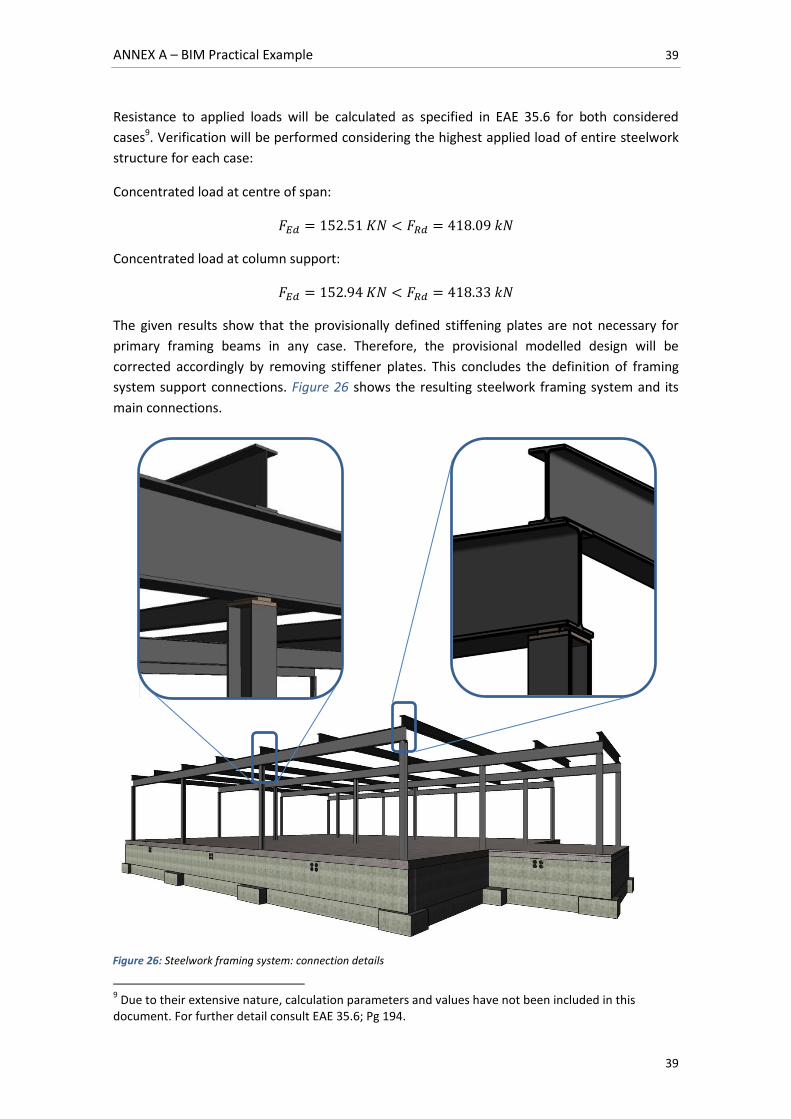
ANNEX A – BIM Practical Example 39
39
Resistance to applied loads will be calculated as specified in EAE 35.6 for both considered
cases9. Verification will be performed considering the highest applied load of entire steelwork
structure for each case:
Concentrated load at centre of span:
Concentrated load at column support:
The given results show that the provisionally defined stiffening plates are not necessary for
primary framing beams in any case. Therefore, the provisional modelled design will be
corrected accordingly by removing stiffener plates. This concludes the definition of framing
system support connections. Figure 26 shows the resulting steelwork framing system and its
main connections.
9 Due to their extensive nature, calculation parameters and values have not been included in this
document. For further detail consult EAE 35.6; Pg 194.
Figure 26: Steelwork framing system: connection details
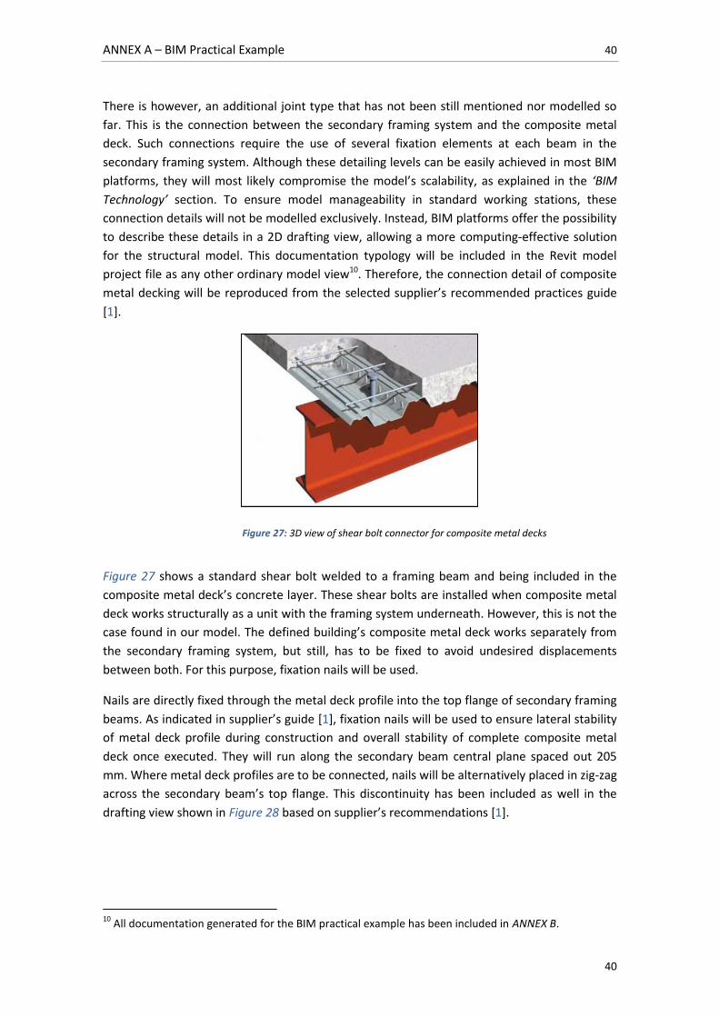
ANNEX A – BIM Practical Example 40
40
There is however, an additional joint type that has not been still mentioned nor modelled so
far. This is the connection between the secondary framing system and the composite metal
deck. Such connections require the use of several fixation elements at each beam in the
secondary framing system. Although these detailing levels can be easily achieved in most BIM
platforms, they will most likely compromise the model’s scalability, as explained in the ‘BIM
Technology’ section. To ensure model manageability in standard working stations, these
connection details will not be modelled exclusively. Instead, BIM platforms offer the possibility
to describe these details in a 2D drafting view, allowing a more computing-effective solution
for the structural model. This documentation typology will be included in the Revit model
project file as any other ordinary model view10. Therefore, the connection detail of composite
metal decking will be reproduced from the selected supplier’s recommended practices guide
[1].
Figure 27 shows a standard shear bolt welded to a framing beam and being included in the
composite metal deck’s concrete layer. These shear bolts are installed when composite metal
deck works structurally as a unit with the framing system underneath. However, this is not the
case found in our model. The defined building’s composite metal deck works separately from
the secondary framing system, but still, has to be fixed to avoid undesired displacements
between both. For this purpose, fixation nails will be used.
Nails are directly fixed through the metal deck profile into the top flange of secondary framing
beams. As indicated in supplier’s guide [1], fixation nails will be used to ensure lateral stability
of metal deck profile during construction and overall stability of complete composite metal
deck once executed. They will run along the secondary beam central plane spaced out 205
mm. Where metal deck profiles are to be connected, nails will be alternatively placed in zig-zag
across the secondary beam’s top flange. This discontinuity has been included as well in the
drafting view shown in Figure 28 based on supplier’s recommendations [1].
10
All documentation generated for the BIM practical example has been included in ANNEX B.
Figure 27: 3D view of shear bolt connector for composite metal decks
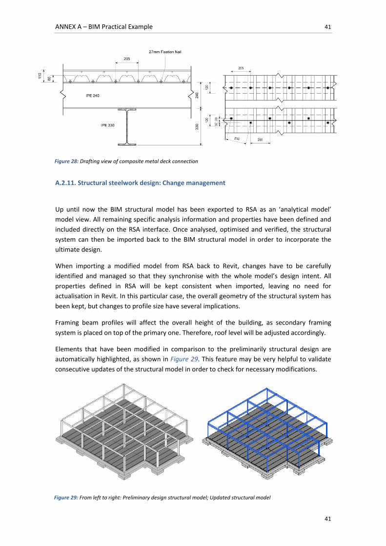
ANNEX A – BIM Practical Example 41
41
A.2.11. Structural steelwork design: Change management
Up until now the BIM structural model has been exported to RSA as an ‘analytical model’
model view. All remaining specific analysis information and properties have been defined and
included directly on the RSA interface. Once analysed, optimised and verified, the structural
system can then be imported back to the BIM structural model in order to incorporate the
ultimate design.
When importing a modified model from RSA back to Revit, changes have to be carefully
identified and managed so that they synchronise with the whole model’s design intent. All
properties defined in RSA will be kept consistent when imported, leaving no need for
actualisation in Revit. In this particular case, the overall geometry of the structural system has
been kept, but changes to profile size have several implications.
Framing beam profiles will affect the overall height of the building, as secondary framing
system is placed on top of the primary one. Therefore, roof level will be adjusted accordingly.
Elements that have been modified in comparison to the preliminarily structural design are
automatically highlighted, as shown in Figure 29. This feature may be very helpful to validate
consecutive updates of the structural model in order to check for necessary modifications.
Figure 28: Drafting view of composite metal deck connection
Figure 29: From left to right: Preliminary design structural model; Updated structural model
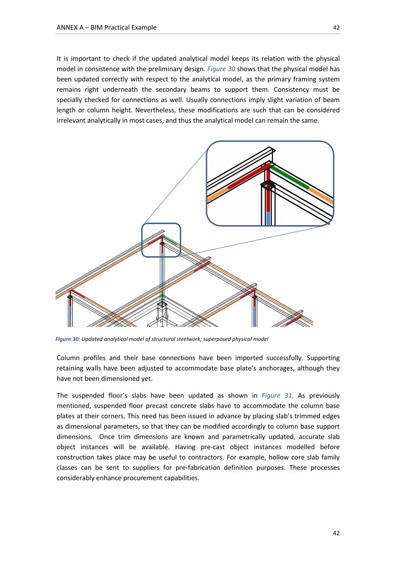
ANNEX A – BIM Practical Example 42
42
It is important to check if the updated analytical model keeps its relation with the physical
model in consistence with the preliminary design. Figure 30 shows that the physical model has
been updated correctly with respect to the analytical model, as the primary framing system
remains right underneath the secondary beams to support them. Consistency must be
specially checked for connections as well. Usually connections imply slight variation of beam
length or column height. Nevertheless, these modifications are such that can be considered
irrelevant analytically in most cases, and thus the analytical model can remain the same.
Column profiles and their base connections have been imported successfully. Supporting
retaining walls have been adjusted to accommodate base plate’s anchorages, although they
have not been dimensioned yet.
The suspended floor’s slabs have been updated as shown in Figure 31. As previously
mentioned, suspended floor precast concrete slabs have to accommodate the column base
plates at their corners. This need has been issued in advance by placing slab’s trimmed edges
as dimensional parameters, so that they can be modified accordingly to column base support
dimensions. Once trim dimensions are known and parametrically updated, accurate slab
object instances will be available. Having pre-cast object instances modelled before
construction takes place may be useful to contractors. For example, hollow core slab family
classes can be sent to suppliers for pre-fabrication definition purposes. These processes
considerably enhance procurement capabilities.
Figure 30: Updated analytical model of structural steelwork; superposed physical model
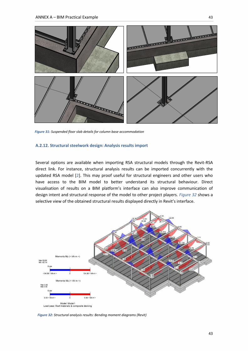
ANNEX A – BIM Practical Example 43
43
A.2.12. Structural steelwork design: Analysis results import
Several options are available when importing RSA structural models through the Revit-RSA
direct link. For instance, structural analysis results can be imported concurrently with the
updated RSA model [2]. This may proof useful for structural engineers and other users who
have access to the BIM model to better understand its structural behaviour. Direct
visualisation of results on a BIM platform’s interface can also improve communication of
design intent and structural response of the model to other project players. Figure 32 shows a
selective view of the obtained structural results displayed directly in Revit’s interface.
Figure 31: Suspended floor slab details for column base accommodation
Figure 32: Structural analysis results: Bending moment diagrams (Revit)
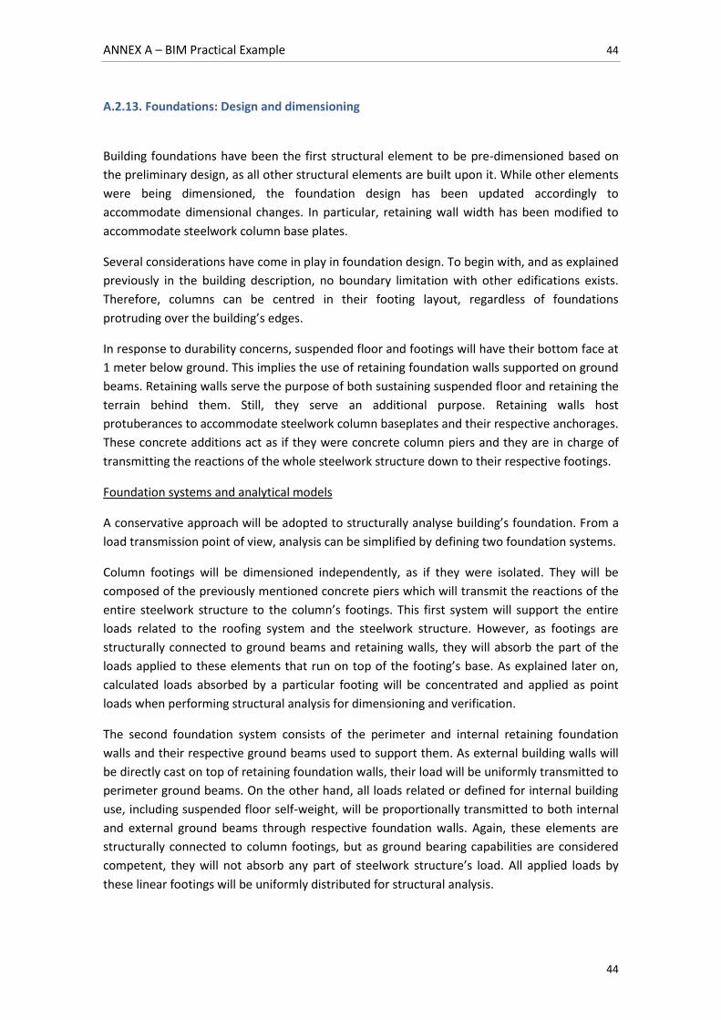
ANNEX A – BIM Practical Example 44
44
A.2.13. Foundations: Design and dimensioning
Building foundations have been the first structural element to be pre-dimensioned based on
the preliminary design, as all other structural elements are built upon it. While other elements
were being dimensioned, the foundation design has been updated accordingly to
accommodate dimensional changes. In particular, retaining wall width has been modified to
accommodate steelwork column base plates.
Several considerations have come in play in foundation design. To begin with, and as explained
previously in the building description, no boundary limitation with other edifications exists.
Therefore, columns can be centred in their footing layout, regardless of foundations
protruding over the building’s edges.
In response to durability concerns, suspended floor and footings will have their bottom face at
1 meter below ground. This implies the use of retaining foundation walls supported on ground
beams. Retaining walls serve the purpose of both sustaining suspended floor and retaining the
terrain behind them. Still, they serve an additional purpose. Retaining walls host
protuberances to accommodate steelwork column baseplates and their respective anchorages.
These concrete additions act as if they were concrete column piers and they are in charge of
transmitting the reactions of the whole steelwork structure down to their respective footings.
Foundation systems and analytical models
A conservative approach will be adopted to structurally analyse building’s foundation. From a
load transmission point of view, analysis can be simplified by defining two foundation systems.
Column footings will be dimensioned independently, as if they were isolated. They will be
composed of the previously mentioned concrete piers which will transmit the reactions of the
entire steelwork structure to the column’s footings. This first system will support the entire
loads related to the roofing system and the steelwork structure. However, as footings are
structurally connected to ground beams and retaining walls, they will absorb the part of the
loads applied to these elements that run on top of the footing’s base. As explained later on,
calculated loads absorbed by a particular footing will be concentrated and applied as point
loads when performing structural analysis for dimensioning and verification.
The second foundation system consists of the perimeter and internal retaining foundation
walls and their respective ground beams used to support them. As external building walls will
be directly cast on top of retaining foundation walls, their load will be uniformly transmitted to
perimeter ground beams. On the other hand, all loads related or defined for internal building
use, including suspended floor self-weight, will be proportionally transmitted to both internal
and external ground beams through respective foundation walls. Again, these elements are
structurally connected to column footings, but as ground bearing capabilities are considered
competent, they will not absorb any part of steelwork structure’s load. All applied loads by
these linear footings will be uniformly distributed for structural analysis.
ANNEX A – BIM Practical Example 45
45
Although being the first element to be preliminarily modelled, foundations will be the last to
be dimensioned. In order to structurally verify the building’s support it has been necessary to
design all other elements previously as to obtain an accurate estimation of their self-weight11.
Once reactions and loads applied to footings and retaining walls are obtained, a proper
structural analysis can be run to verify the ultimate design of foundations.
Before proceeding to obtaining absorbed load values for both foundation systems, the loads
applied to the entire foundation scheme will be specified.
Load assignment
Applied loads comply with CTE DB-SE-AE: 2009 [6] and are as follows:
Dead Loads (DL):
Self-weight: It will be defined by retaining wall and pier section definition.
Composite metal decking: The chosen 110mm thick composite metal deck weights
according to supplier’s catalogue [11].
Roof waterproofing and sloping materials: A value of will be considered.
External walls: A linear distributed load of will be considered.
Precast hollow-core section concrete slabs: A value of will be considered.
The given value includes 50mm concrete compression layer weight.
Internal walls: An assumed specific weight of 1.2 kN/m² for internal walls will be
applied. Based on the building’s predesign documents, there are 35 linear meters of
internal walls with an approximate height of 3 meters. This sums up to 126 kN
uniformly distributed within 15x15 m² according to CTE DB-SE-AE: 2009, resulting in
0.56 KN/m².
Floor finishing layers: Based on preliminary architectural design, a 10mm PVC layer
will be used as floor finishing layer. An assumed specific weight of 0.14 kN/m² will be
considered. Floor finish weight will not be taken into account for the scope of an
approached dimensioning.
Other additional dead loads are neglected for the scope of an approached
dimensioning.
Live Loads12 (LL):
Roof service overloads: As described in the building functionality and requirements,
the building’s roof will only be accessible for maintenance operations (G1). Roof slope
is inferior to 20º, implying uniformly distributed overloads of 1 KN/m² and point
overloads of 2KN.
11
The values assigned to weight of external walls and roof finishing layers are explained in detail in subsections A.2.15 to A.2.19 12 As pointed in CTE DB-SE-AE 3.1.1.7, live loads already include alternate loading effects.
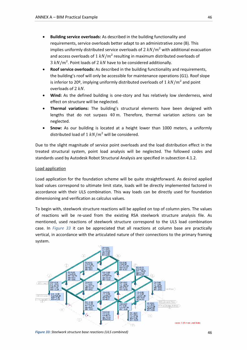
ANNEX A – BIM Practical Example 46
46
Building service overloads: As described in the building functionality and
requirements, service overloads better adapt to an administrative zone (B). This
implies uniformly distributed service overloads of with additional evacuation
and access overloads of resulting in maximum distributed overloads of
. Point loads of have to be considered additionally.
Roof service overloads: As described in the building functionality and requirements,
the building’s roof will only be accessible for maintenance operations (G1). Roof slope
is inferior to 20º, implying uniformly distributed overloads of and point
overloads of .
Wind: As the defined building is one-story and has relatively low slenderness, wind
effect on structure will be neglected.
Thermal variations: The building’s structural elements have been designed with
lengths that do not surpass . Therefore, thermal variation actions can be
neglected.
Snow: As our building is located at a height lower than 1000 meters, a uniformly
distributed load of will be considered.
Due to the slight magnitude of service point overloads and the load distribution effect in the
treated structural system, point load analysis will be neglected. The followed codes and
standards used by Autodesk Robot Structural Analysis are specified in subsection 4.1.2.
Load application
Load application for the foundation scheme will be quite straightforward. As desired applied
load values correspond to ultimate limit state, loads will be directly implemented factored in
accordance with their ULS combination. This way loads can be directly used for foundation
dimensioning and verification as calculus values.
To begin with, steelwork structure reactions will be applied on top of column piers. The values
of reactions will be re-used from the existing RSA steelwork structure analysis file. As
mentioned, used reactions of steelwork structure correspond to the ULS load combination
case. In Figure 33 it can be appreciated that all reactions at column base are practically
vertical, in accordance with the articulated nature of their connections to the primary framing
system.
Figure 33: Steelwork structure base reactions (ULS combined)
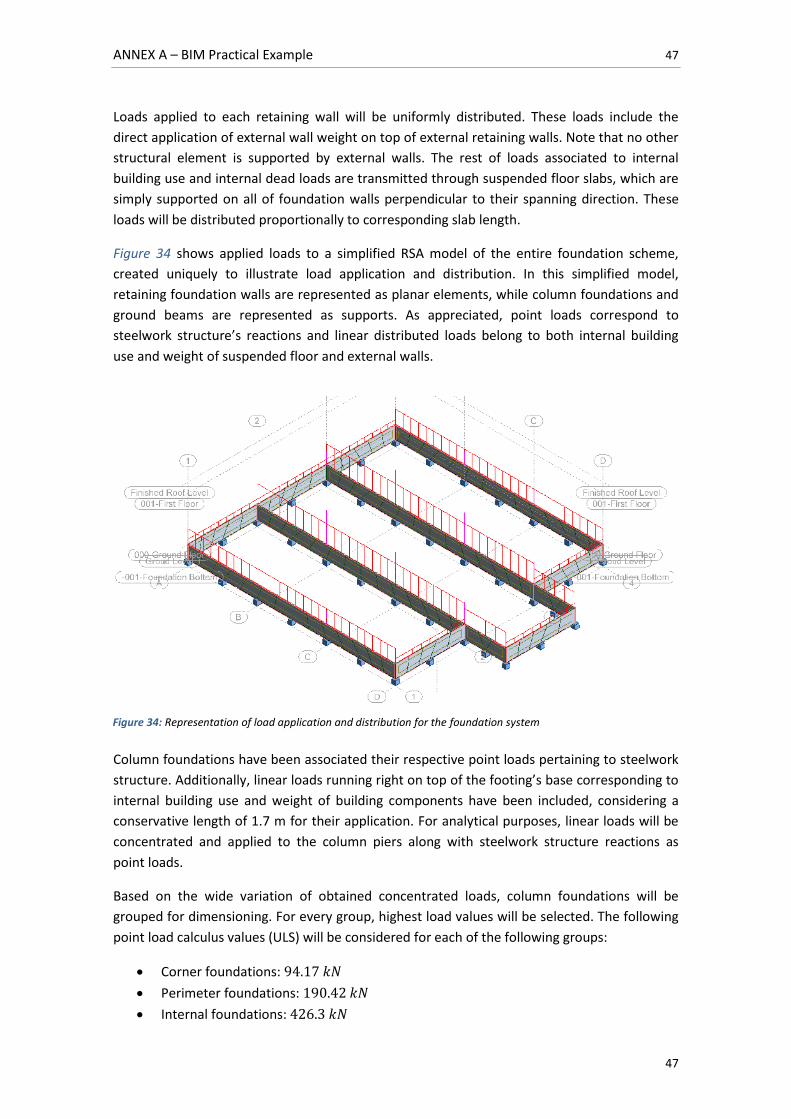
ANNEX A – BIM Practical Example 47
47
Loads applied to each retaining wall will be uniformly distributed. These loads include the
direct application of external wall weight on top of external retaining walls. Note that no other
structural element is supported by external walls. The rest of loads associated to internal
building use and internal dead loads are transmitted through suspended floor slabs, which are
simply supported on all of foundation walls perpendicular to their spanning direction. These
loads will be distributed proportionally to corresponding slab length.
Figure 34 shows applied loads to a simplified RSA model of the entire foundation scheme,
created uniquely to illustrate load application and distribution. In this simplified model,
retaining foundation walls are represented as planar elements, while column foundations and
ground beams are represented as supports. As appreciated, point loads correspond to
steelwork structure’s reactions and linear distributed loads belong to both internal building
use and weight of suspended floor and external walls.
Column foundations have been associated their respective point loads pertaining to steelwork
structure. Additionally, linear loads running right on top of the footing’s base corresponding to
internal building use and weight of building components have been included, considering a
conservative length of 1.7 m for their application. For analytical purposes, linear loads will be
concentrated and applied to the column piers along with steelwork structure reactions as
point loads.
Based on the wide variation of obtained concentrated loads, column foundations will be
grouped for dimensioning. For every group, highest load values will be selected. The following
point load calculus values (ULS) will be considered for each of the following groups:
Corner foundations:
Perimeter foundations:
Internal foundations:
Figure 34: Representation of load application and distribution for the foundation system
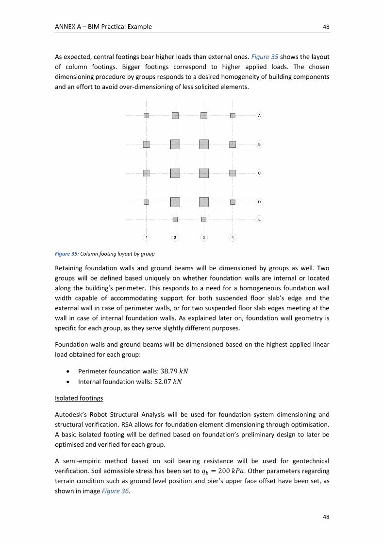
ANNEX A – BIM Practical Example 48
48
As expected, central footings bear higher loads than external ones. Figure 35 shows the layout
of column footings. Bigger footings correspond to higher applied loads. The chosen
dimensioning procedure by groups responds to a desired homogeneity of building components
and an effort to avoid over-dimensioning of less solicited elements.
Figure 35: Column footing layout by group
Retaining foundation walls and ground beams will be dimensioned by groups as well. Two
groups will be defined based uniquely on whether foundation walls are internal or located
along the building’s perimeter. This responds to a need for a homogeneous foundation wall
width capable of accommodating support for both suspended floor slab’s edge and the
external wall in case of perimeter walls, or for two suspended floor slab edges meeting at the
wall in case of internal foundation walls. As explained later on, foundation wall geometry is
specific for each group, as they serve slightly different purposes.
Foundation walls and ground beams will be dimensioned based on the highest applied linear
load obtained for each group:
Perimeter foundation walls:
Internal foundation walls:
Isolated footings
Autodesk’s Robot Structural Analysis will be used for foundation system dimensioning and
structural verification. RSA allows for foundation element dimensioning through optimisation.
A basic isolated footing will be defined based on foundation’s preliminary design to later be
optimised and verified for each group.
A semi-empiric method based on soil bearing resistance will be used for geotechnical
verification. Soil admissible stress has been set to . Other parameters regarding
terrain condition such as ground level position and pier’s upper face offset have been set, as
shown in image Figure 36.
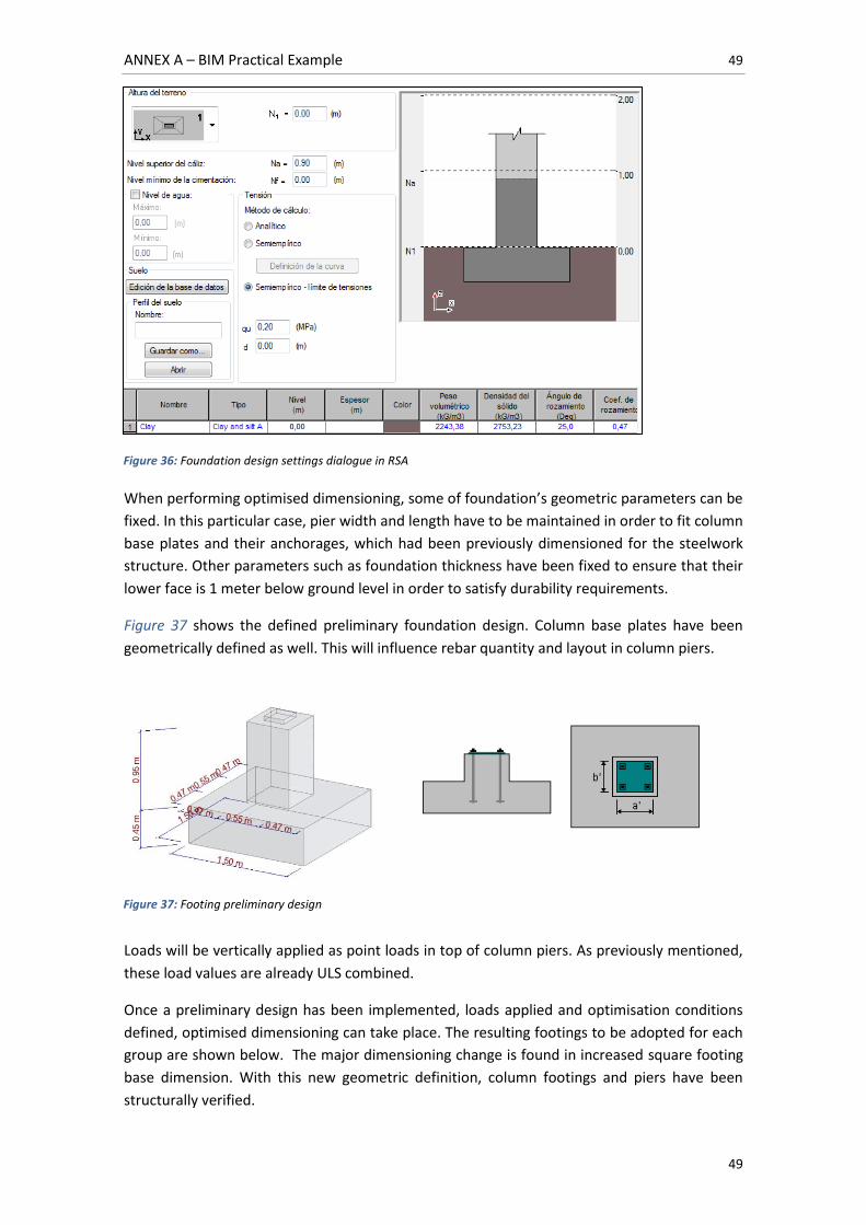
ANNEX A – BIM Practical Example 49
49
When performing optimised dimensioning, some of foundation’s geometric parameters can be
fixed. In this particular case, pier width and length have to be maintained in order to fit column
base plates and their anchorages, which had been previously dimensioned for the steelwork
structure. Other parameters such as foundation thickness have been fixed to ensure that their
lower face is 1 meter below ground level in order to satisfy durability requirements.
Figure 37 shows the defined preliminary foundation design. Column base plates have been
geometrically defined as well. This will influence rebar quantity and layout in column piers.
Loads will be vertically applied as point loads in top of column piers. As previously mentioned,
these load values are already ULS combined.
Once a preliminary design has been implemented, loads applied and optimisation conditions
defined, optimised dimensioning can take place. The resulting footings to be adopted for each
group are shown below. The major dimensioning change is found in increased square footing
base dimension. With this new geometric definition, column footings and piers have been
structurally verified.
Figure 36: Foundation design settings dialogue in RSA
Figure 37: Footing preliminary design
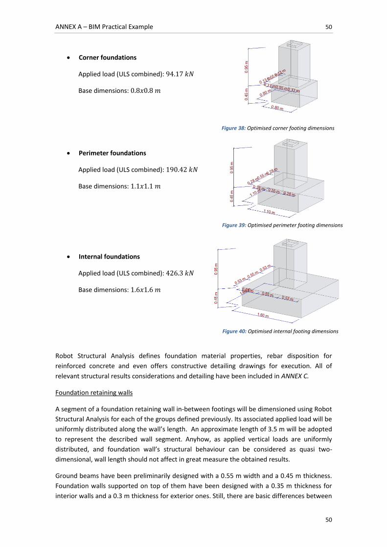
ANNEX A – BIM Practical Example 50
50
Corner foundations
Applied load (ULS combined):
Base dimensions:
Perimeter foundations
Applied load (ULS combined):
Base dimensions:
Internal foundations
Applied load (ULS combined):
Base dimensions:
Robot Structural Analysis defines foundation material properties, rebar disposition for
reinforced concrete and even offers constructive detailing drawings for execution. All of
relevant structural results considerations and detailing have been included in ANNEX C.
Foundation retaining walls
A segment of a foundation retaining wall in-between footings will be dimensioned using Robot
Structural Analysis for each of the groups defined previously. Its associated applied load will be
uniformly distributed along the wall’s length. An approximate length of 3.5 m will be adopted
to represent the described wall segment. Anyhow, as applied vertical loads are uniformly
distributed, and foundation wall’s structural behaviour can be considered as quasi two-
dimensional, wall length should not affect in great measure the obtained results.
Ground beams have been preliminarily designed with a 0.55 m width and a 0.45 m thickness.
Foundation walls supported on top of them have been designed with a 0.35 m thickness for
interior walls and a 0.3 m thickness for exterior ones. Still, there are basic differences between
Figure 38: Optimised corner footing dimensions
Figure 39: Optimised perimeter footing dimensions
Figure 40: Optimised internal footing dimensions
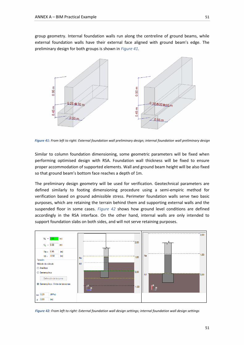
ANNEX A – BIM Practical Example 51
51
group geometry. Internal foundation walls run along the centreline of ground beams, while
external foundation walls have their external face aligned with ground beam’s edge. The
preliminary design for both groups is shown in Figure 41.
Similar to column foundation dimensioning, some geometric parameters will be fixed when
performing optimised design with RSA. Foundation wall thickness will be fixed to ensure
proper accommodation of supported elements. Wall and ground beam height will be also fixed
so that ground beam’s bottom face reaches a depth of 1m.
The preliminary design geometry will be used for verification. Geotechnical parameters are
defined similarly to footing dimensioning procedure using a semi-empiric method for
verification based on ground admissible stress. Perimeter foundation walls serve two basic
purposes, which are retaining the terrain behind them and supporting external walls and the
suspended floor in some cases. Figure 42 shows how ground level conditions are defined
accordingly in the RSA interface. On the other hand, internal walls are only intended to
support foundation slabs on both sides, and will not serve retaining purposes.
Figure 41: From left to right: External foundation wall preliminary design; internal foundation wall preliminary design
Figure 42: From left to right: External foundation wall design settings; internal foundation wall design settings
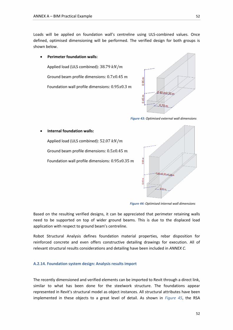
ANNEX A – BIM Practical Example 52
52
Loads will be applied on foundation wall’s centreline using ULS-combined values. Once
defined, optimised dimensioning will be performed. The verified design for both groups is
shown below.
Perimeter foundation walls:
Applied load (ULS combined):
Ground beam profile dimensions:
Foundation wall profile dimensions:
Internal foundation walls:
Applied load (ULS combined):
Ground beam profile dimensions:
Foundation wall profile dimensions:
Based on the resulting verified designs, it can be appreciated that perimeter retaining walls
need to be supported on top of wider ground beams. This is due to the displaced load
application with respect to ground beam’s centreline.
Robot Structural Analysis defines foundation material properties, rebar disposition for
reinforced concrete and even offers constructive detailing drawings for execution. All of
relevant structural results considerations and detailing have been included in ANNEX C.
A.2.14. Foundation system design: Analysis results import
The recently dimensioned and verified elements can be imported to Revit through a direct link,
similar to what has been done for the steelwork structure. The foundations appear
represented in Revit’s structural model as object instances. All structural attributes have been
implemented in these objects to a great level of detail. As shown in Figure 45, the RSA
Figure 43: Optimised external wall dimensions
Figure 44: Optimised internal wall dimensions
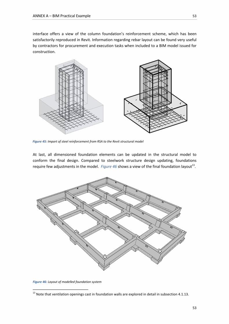
ANNEX A – BIM Practical Example 53
53
interface offers a view of the column foundation’s reinforcement scheme, which has been
satisfactorily reproduced in Revit. Information regarding rebar layout can be found very useful
by contractors for procurement and execution tasks when included to a BIM model issued for
construction.
At last, all dimensioned foundation elements can be updated in the structural model to
conform the final design. Compared to steelwork structure design updating, foundations
require few adjustments in the model. Figure 46 shows a view of the final foundation layout13.
Figure 46: Layout of modelled foundation system
13
Note that ventilation openings cast in foundation walls are explored in detail in subsection 4.1.13.
Figure 45: Import of steel reinforcement from RSA to the Revit structural model
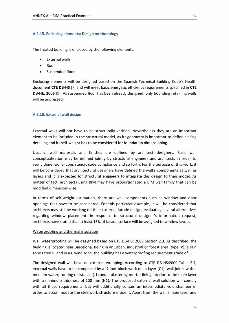
ANNEX A – BIM Practical Example 54
54
A.2.15. Enclosing elements: Design methodology
The treated building is enclosed by the following elements:
External walls
Roof
Suspended floor
Enclosing elements will be designed based on the Spanish Technical Building Code’s Health
document CTE DB-HS [7] and will meet basic energetic efficiency requirements specified in CTE
DB-HE: 2006 [9]. As suspended floor has been already designed, only bounding retaining walls
will be addressed.
A.2.16. External wall design
External walls will not have to be structurally verified. Nevertheless they are an important
element to be included in the structural model, as its geometry is important to define closing
detailing and its self-weight has to be considered for foundation dimensioning.
Usually, wall materials and finishes are defined by architect designers. Basic wall
conceptualisation may be defined jointly by structural engineers and architects in order to
verify dimensional consistency, code compliance and so forth. For the purpose of this work, it
will be considered that architectural designers have defined the wall’s components as well as
layers and it is expected for structural engineers to integrate this design to their model. As
matter of fact, architects using BIM may have proportionated a BIM wall family that can be
modified dimension-wise.
In terms of self-weight estimation, there are wall components such as window and door
openings that have to be considered. For this particular example, it will be considered that
architects may still be working on their external facade design, evaluating several alternatives
regarding window placement. In response to structural designer’s information request,
architects have stated that at least 15% of facade surface will be assigned to window layout.
Waterproofing and thermal insulation
Wall waterproofing will be designed based on CTE DB-HS: 2009 Section 2.3. As described, the
building is located near Barcelona. Being in an urban, industrial or forest area (type IV), a rain
zone rated III and in a C wind zone, the building has a waterproofing requirement grade of 1.
The designed wall will have no external wrapping. According to CTE DB-HS:2009 Table 2.7,
external walls have to be composed by a ½ foot block-work main layer (C1), wall joints with a
medium waterproofing resistance (J1) and a plastering mortar lining interior to the main layer
with a minimum thickness of 100 mm (N1). The proposed external wall solution will comply
with all these requirements, but will additionally contain an intermediate void chamber in
order to accommodate the steelwork structure inside it. Apart from the wall’s main layer and
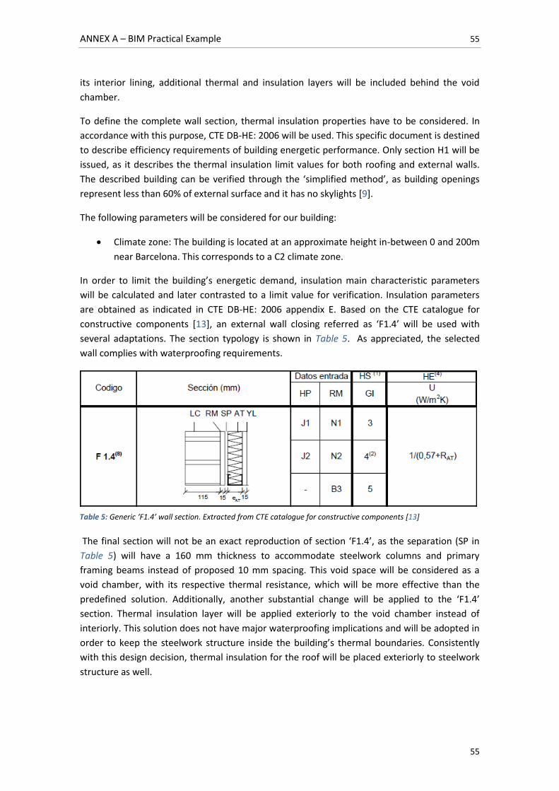
ANNEX A – BIM Practical Example 55
55
its interior lining, additional thermal and insulation layers will be included behind the void
chamber.
To define the complete wall section, thermal insulation properties have to be considered. In
accordance with this purpose, CTE DB-HE: 2006 will be used. This specific document is destined
to describe efficiency requirements of building energetic performance. Only section H1 will be
issued, as it describes the thermal insulation limit values for both roofing and external walls.
The described building can be verified through the ‘simplified method’, as building openings
represent less than 60% of external surface and it has no skylights [9].
The following parameters will be considered for our building:
Climate zone: The building is located at an approximate height in-between 0 and 200m
near Barcelona. This corresponds to a C2 climate zone.
In order to limit the building’s energetic demand, insulation main characteristic parameters
will be calculated and later contrasted to a limit value for verification. Insulation parameters
are obtained as indicated in CTE DB-HE: 2006 appendix E. Based on the CTE catalogue for
constructive components [13], an external wall closing referred as ‘F1.4’ will be used with
several adaptations. The section typology is shown in Table 5. As appreciated, the selected
wall complies with waterproofing requirements.
The final section will not be an exact reproduction of section ‘F1.4’, as the separation (SP in
Table 5) will have a 160 mm thickness to accommodate steelwork columns and primary
framing beams instead of proposed 10 mm spacing. This void space will be considered as a
void chamber, with its respective thermal resistance, which will be more effective than the
predefined solution. Additionally, another substantial change will be applied to the ‘F1.4’
section. Thermal insulation layer will be applied exteriorly to the void chamber instead of
interiorly. This solution does not have major waterproofing implications and will be adopted in
order to keep the steelwork structure inside the building’s thermal boundaries. Consistently
with this design decision, thermal insulation for the roof will be placed exteriorly to steelwork
structure as well.
Table 5: Generic ‘F1.4’ wall section. Extracted from CTE catalogue for constructive components [13]
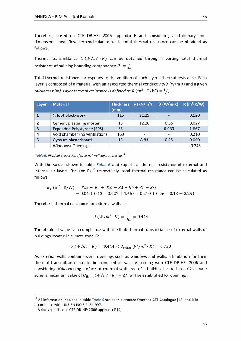
ANNEX A – BIM Practical Example 56
56
Therefore, based on CTE DB-HE: 2006 appendix E and considering a stationary one-
dimensional heat flow perpendicular to walls, total thermal resistance can be obtained as
follows:
Thermal transmittance can be obtained through inverting total thermal
resistance of building bounding components:
.
Total thermal resistance corresponds to the addition of each layer’s thermal resistance. Each
layer is composed of a material with an associated thermal conductivity λ (W/m·K) and a given
thickness t (m). Layer thermal resistance is defined as ⁄ .
With the values shown in table Table 6 and superficial thermal resistance of external and
internal air layers, Rse and Rsi15 respectively, total thermal resistance can be calculated as
follows:
Therefore, thermal resistance for external walls is:
The obtained value is in compliance with the limit thermal transmittance of external walls of
buildings located in climate zone C2:
As external walls contain several openings such as windows and walls, a limitation for their
thermal transmittance has to be complied as well. According with CTE DB-HE: 2006 and
considering 30% opening surface of external wall area of a building located in a C2 climate
zone, a maximum value of will be established for openings.
14
All information included in table Table 6 has been extracted from the CTE Catalogue [13] and is in accordance with UNE EN ISO 6 946:1997. 15
Values specified in CTE DB-HE: 2006 appendix E [9]
Layer Material Thickness (mm)
γ (kN/m³) λ (W/m·K) R (m²·K/W)
1 ½ foot block-work 115 21.29 - 0.120
2 Cement plastering mortar 15 12.26 0.55 0.027 3 Expanded Polystyrene (EPS) 65 - 0.039 1.667 4 Void chamber (no ventilation) 160 - - 0.210 5 Gypsum plasterboard 15 8.83 0.25 0.060
- Windows/ Openings - - - ≥0.345
Table 6: Physical properties of external wall layer materials14
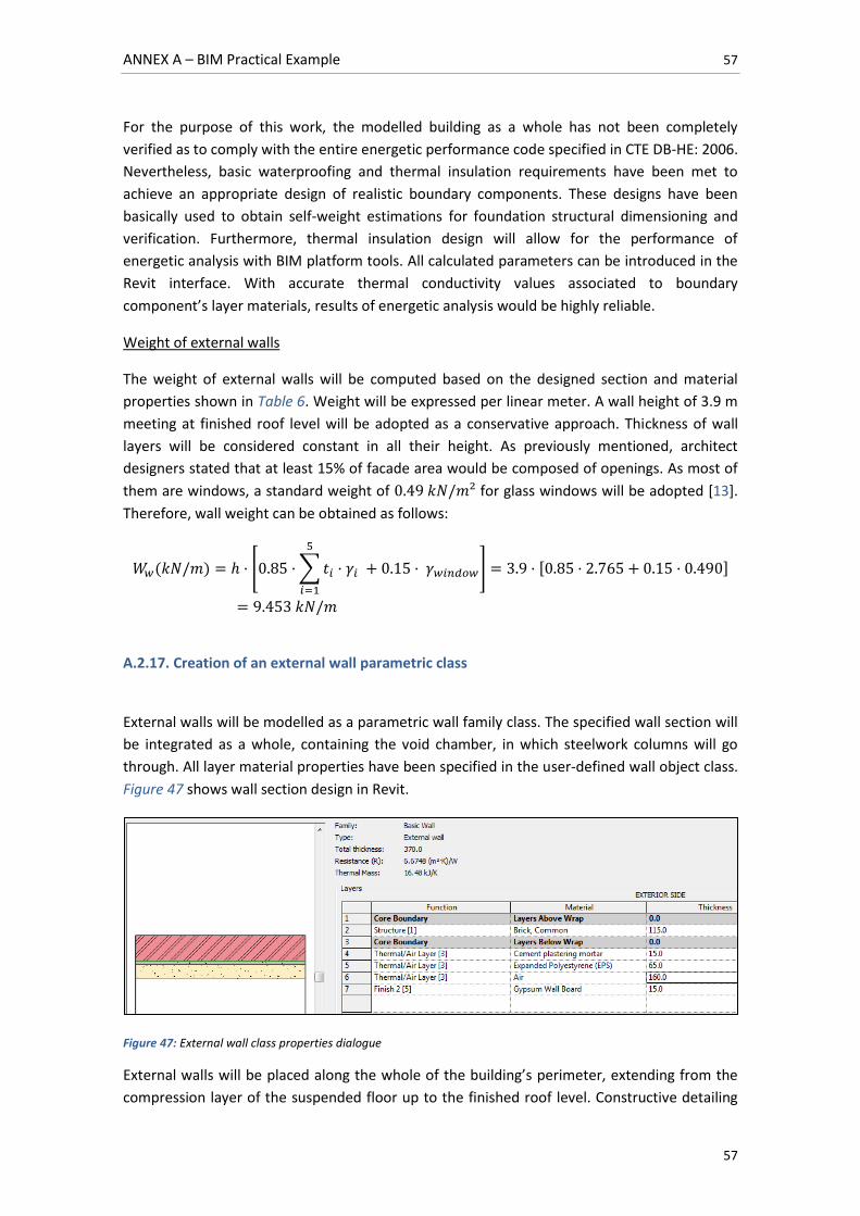
ANNEX A – BIM Practical Example 57
57
For the purpose of this work, the modelled building as a whole has not been completely
verified as to comply with the entire energetic performance code specified in CTE DB-HE: 2006.
Nevertheless, basic waterproofing and thermal insulation requirements have been met to
achieve an appropriate design of realistic boundary components. These designs have been
basically used to obtain self-weight estimations for foundation structural dimensioning and
verification. Furthermore, thermal insulation design will allow for the performance of
energetic analysis with BIM platform tools. All calculated parameters can be introduced in the
Revit interface. With accurate thermal conductivity values associated to boundary
component’s layer materials, results of energetic analysis would be highly reliable.
Weight of external walls
The weight of external walls will be computed based on the designed section and material
properties shown in Table 6. Weight will be expressed per linear meter. A wall height of 3.9 m
meeting at finished roof level will be adopted as a conservative approach. Thickness of wall
layers will be considered constant in all their height. As previously mentioned, architect
designers stated that at least 15% of facade area would be composed of openings. As most of
them are windows, a standard weight of for glass windows will be adopted [13].
Therefore, wall weight can be obtained as follows:
[ ∑
] [ ]
A.2.17. Creation of an external wall parametric class
External walls will be modelled as a parametric wall family class. The specified wall section will
be integrated as a whole, containing the void chamber, in which steelwork columns will go
through. All layer material properties have been specified in the user-defined wall object class.
Figure 47 shows wall section design in Revit.
Figure 47: External wall class properties dialogue
External walls will be placed along the whole of the building’s perimeter, extending from the
compression layer of the suspended floor up to the finished roof level. Constructive detailing
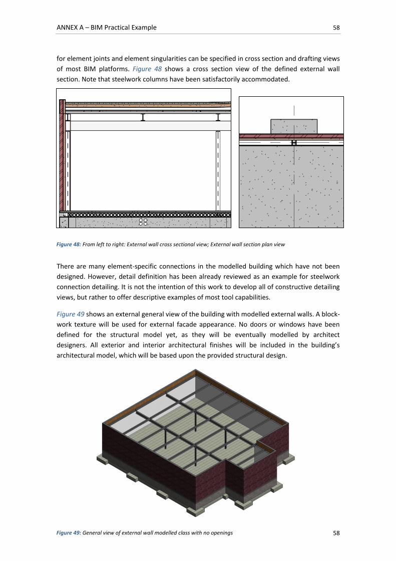
ANNEX A – BIM Practical Example 58
58
for element joints and element singularities can be specified in cross section and drafting views
of most BIM platforms. Figure 48 shows a cross section view of the defined external wall
section. Note that steelwork columns have been satisfactorily accommodated.
There are many element-specific connections in the modelled building which have not been
designed. However, detail definition has been already reviewed as an example for steelwork
connection detailing. It is not the intention of this work to develop all of constructive detailing
views, but rather to offer descriptive examples of most tool capabilities.
Figure 49 shows an external general view of the building with modelled external walls. A block-
work texture will be used for external facade appearance. No doors or windows have been
defined for the structural model yet, as they will be eventually modelled by architect
designers. All exterior and interior architectural finishes will be included in the building’s
architectural model, which will be based upon the provided structural design.
Figure 48: From left to right: External wall cross sectional view; External wall section plan view
Figure 49: General view of external wall modelled class with no openings
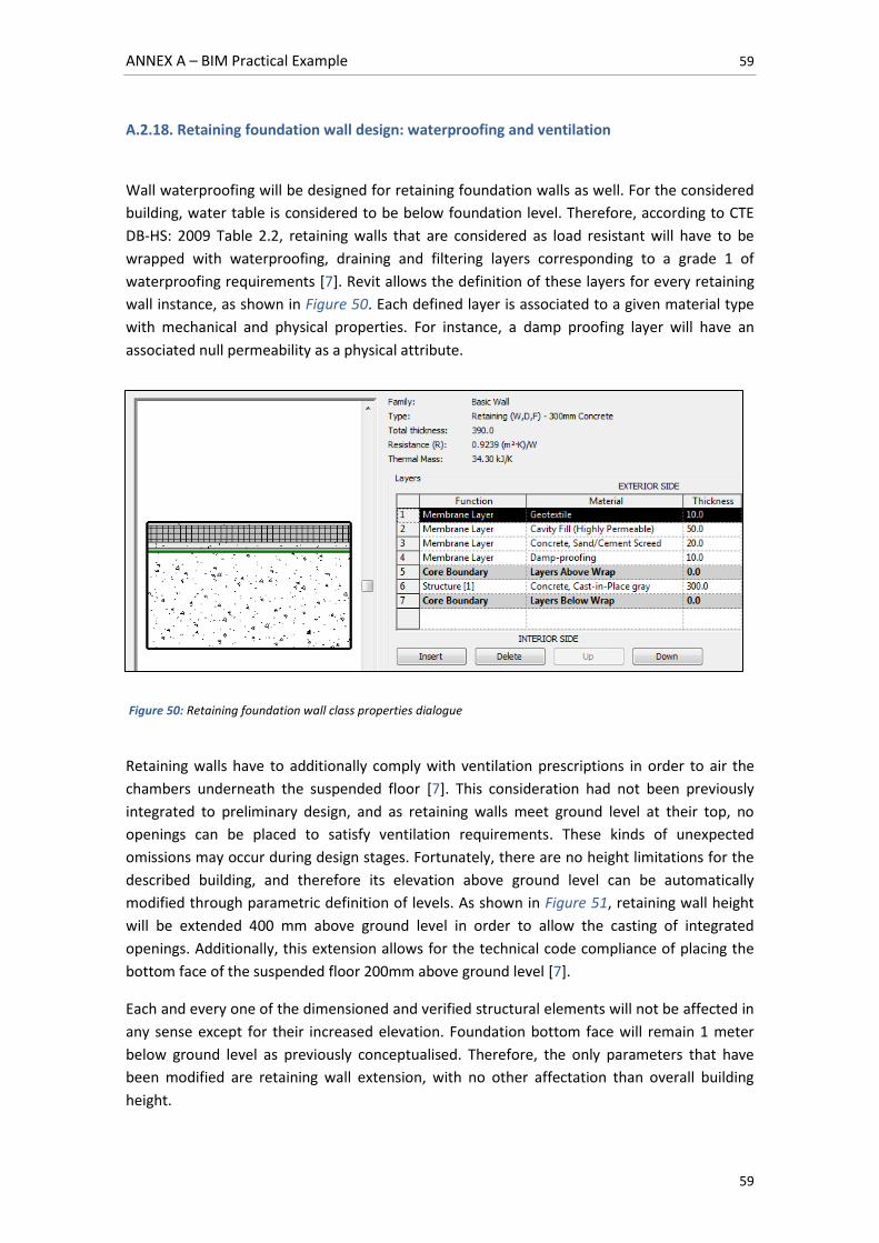
ANNEX A – BIM Practical Example 59
59
A.2.18. Retaining foundation wall design: waterproofing and ventilation
Wall waterproofing will be designed for retaining foundation walls as well. For the considered
building, water table is considered to be below foundation level. Therefore, according to CTE
DB-HS: 2009 Table 2.2, retaining walls that are considered as load resistant will have to be
wrapped with waterproofing, draining and filtering layers corresponding to a grade 1 of
waterproofing requirements [7]. Revit allows the definition of these layers for every retaining
wall instance, as shown in Figure 50. Each defined layer is associated to a given material type
with mechanical and physical properties. For instance, a damp proofing layer will have an
associated null permeability as a physical attribute.
Figure 50: Retaining foundation wall class properties dialogue
Retaining walls have to additionally comply with ventilation prescriptions in order to air the
chambers underneath the suspended floor [7]. This consideration had not been previously
integrated to preliminary design, and as retaining walls meet ground level at their top, no
openings can be placed to satisfy ventilation requirements. These kinds of unexpected
omissions may occur during design stages. Fortunately, there are no height limitations for the
described building, and therefore its elevation above ground level can be automatically
modified through parametric definition of levels. As shown in Figure 51, retaining wall height
will be extended 400 mm above ground level in order to allow the casting of integrated
openings. Additionally, this extension allows for the technical code compliance of placing the
bottom face of the suspended floor 200mm above ground level [7].
Each and every one of the dimensioned and verified structural elements will not be affected in
any sense except for their increased elevation. Foundation bottom face will remain 1 meter
below ground level as previously conceptualised. Therefore, the only parameters that have
been modified are retaining wall extension, with no other affectation than overall building
height.
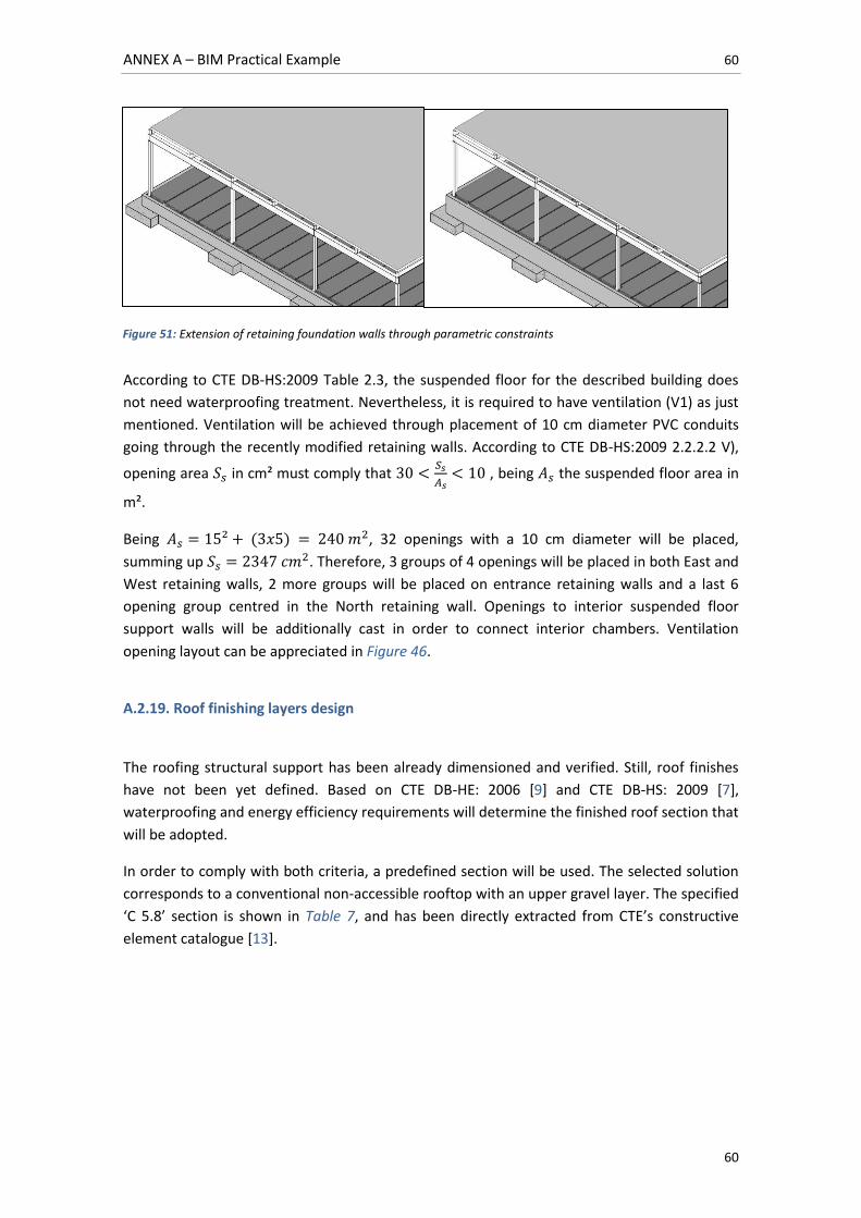
ANNEX A – BIM Practical Example 60
60
According to CTE DB-HS:2009 Table 2.3, the suspended floor for the described building does
not need waterproofing treatment. Nevertheless, it is required to have ventilation (V1) as just
mentioned. Ventilation will be achieved through placement of 10 cm diameter PVC conduits
going through the recently modified retaining walls. According to CTE DB-HS:2009 2.2.2.2 V),
opening area in cm² must comply that
, being the suspended floor area in
m².
Being , 32 openings with a 10 cm diameter will be placed,
summing up . Therefore, 3 groups of 4 openings will be placed in both East and
West retaining walls, 2 more groups will be placed on entrance retaining walls and a last 6
opening group centred in the North retaining wall. Openings to interior suspended floor
support walls will be additionally cast in order to connect interior chambers. Ventilation
opening layout can be appreciated in Figure 46.
A.2.19. Roof finishing layers design
The roofing structural support has been already dimensioned and verified. Still, roof finishes
have not been yet defined. Based on CTE DB-HE: 2006 [9] and CTE DB-HS: 2009 [7],
waterproofing and energy efficiency requirements will determine the finished roof section that
will be adopted.
In order to comply with both criteria, a predefined section will be used. The selected solution
corresponds to a conventional non-accessible rooftop with an upper gravel layer. The specified
‘C 5.8’ section is shown in Table 7, and has been directly extracted from CTE’s constructive
element catalogue [13].
Figure 51: Extension of retaining foundation walls through parametric constraints
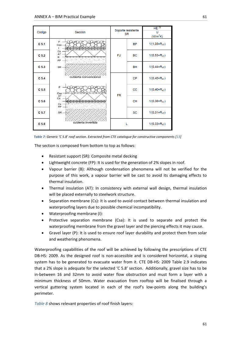
ANNEX A – BIM Practical Example 61
61
The section is composed from bottom to top as follows:
Resistant support (SR): Composite metal decking
Lightweight concrete (FP): It is used for the generation of 2% slopes in roof.
Vapour barrier (B): Although condensation phenomena will not be verified for the
purpose of this work, a vapour barrier will be cast to avoid its damaging effects to
thermal insulation.
Thermal insulation (AT): In consistency with external wall design, thermal insulation
will be placed externally to steelwork structure.
Separation membrane (Cs): It is used to avoid contact between thermal insulation and
waterproofing layers due to possible chemical incompatibility.
Waterproofing membrane (I):
Protective separation membrane (Csa): It is used to separate and protect the
waterproofing membrane from the gravel layer and the piercing effects it may cause.
Gravel layer (P): It is used to ensure roof layer durability and protect them from solar
and weathering phenomena.
Waterproofing capabilities of the roof will be achieved by following the prescriptions of CTE
DB-HS: 2009. As the designed roof is non-accessible and is considered horizontal, a sloping
system has to be generated to evacuate water from it. CTE DB-HS: 2009 Table 2.9 indicates
that a 2% slope is adequate for the selected ‘C 5.8’ section. Additionally, gravel size has to be
in-between 16 and 32mm to avoid water flow obstruction and must form a layer with a
minimum thickness of 50mm. Water evacuation from rooftop will be finalised through a
vertical guttering system located in each of the roof’s low-points along the building’s
perimeter.
Table 8 shows relevant properties of roof finish layers:
Table 7: Generic ‘C 5.8’ roof section. Extracted from CTE catalogue for constructive components [13]
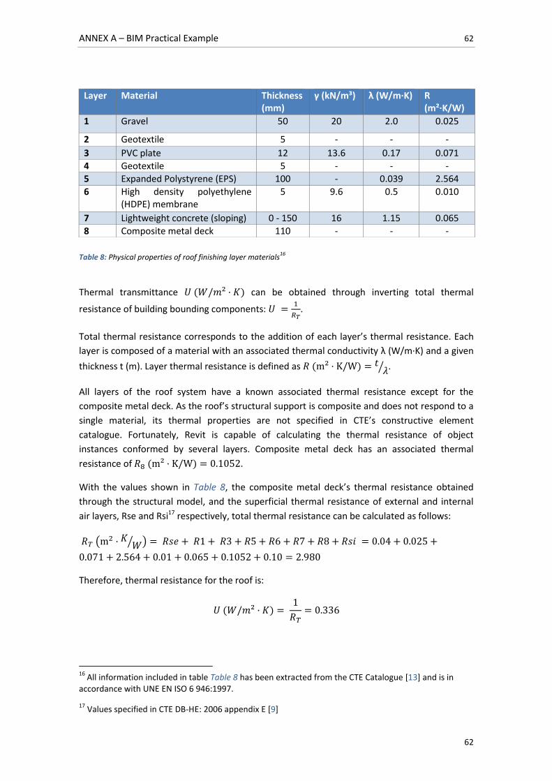
ANNEX A – BIM Practical Example 62
62
Table 8: Physical properties of roof finishing layer materials
16
Thermal transmittance can be obtained through inverting total thermal
resistance of building bounding components:
.
Total thermal resistance corresponds to the addition of each layer’s thermal resistance. Each
layer is composed of a material with an associated thermal conductivity λ (W/m·K) and a given
thickness t (m). Layer thermal resistance is defined as ⁄ .
All layers of the roof system have a known associated thermal resistance except for the
composite metal deck. As the roof’s structural support is composite and does not respond to a
single material, its thermal properties are not specified in CTE’s constructive element
catalogue. Fortunately, Revit is capable of calculating the thermal resistance of object
instances conformed by several layers. Composite metal deck has an associated thermal
resistance of .
With the values shown in Table 8, the composite metal deck’s thermal resistance obtained
through the structural model, and the superficial thermal resistance of external and internal
air layers, Rse and Rsi17 respectively, total thermal resistance can be calculated as follows:
( ⁄ )
Therefore, thermal resistance for the roof is:
16
All information included in table Table 8 has been extracted from the CTE Catalogue [13] and is in accordance with UNE EN ISO 6 946:1997.
17 Values specified in CTE DB-HE: 2006 appendix E [9]
Layer Material Thickness (mm)
γ (kN/m³) λ (W/m·K) R (m²·K/W)
1 Gravel 50 20 2.0 0.025
2 Geotextile 5 - - -
3 PVC plate 12 13.6 0.17 0.071
4 Geotextile 5 - - - 5 Expanded Polystyrene (EPS) 100 - 0.039 2.564
6 High density polyethylene (HDPE) membrane
5 9.6 0.5 0.010
7 Lightweight concrete (sloping) 0 - 150 16 1.15 0.065
8 Composite metal deck 110 - - -
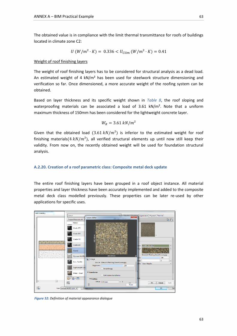
ANNEX A – BIM Practical Example 63
63
The obtained value is in compliance with the limit thermal transmittance for roofs of buildings
located in climate zone C2:
Weight of roof finishing layers
The weight of roof finishing layers has to be considered for structural analysis as a dead load.
An estimated weight of 4 kN/m² has been used for steelwork structure dimensioning and
verification so far. Once dimensioned, a more accurate weight of the roofing system can be
obtained.
Based on layer thickness and its specific weight shown in Table 8, the roof sloping and
waterproofing materials can be associated a load of 3.61 kN/m². Note that a uniform
maximum thickness of 150mm has been considered for the lightweight concrete layer.
Given that the obtained load is inferior to the estimated weight for roof
finishing materials , all verified structural elements up until now still keep their
validity. From now on, the recently obtained weight will be used for foundation structural
analysis.
A.2.20. Creation of a roof parametric class: Composite metal deck update
The entire roof finishing layers have been grouped in a roof object instance. All material
properties and layer thickness have been accurately implemented and added to the composite
metal deck class modelled previously. These properties can be later re-used by other
applications for specific uses.
Figure 52: Definition of material appearance dialogue
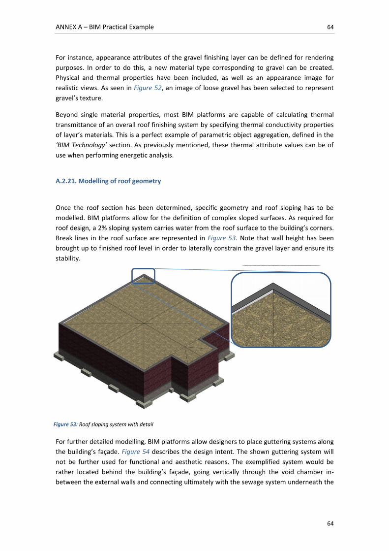
ANNEX A – BIM Practical Example 64
64
For instance, appearance attributes of the gravel finishing layer can be defined for rendering
purposes. In order to do this, a new material type corresponding to gravel can be created.
Physical and thermal properties have been included, as well as an appearance image for
realistic views. As seen in Figure 52, an image of loose gravel has been selected to represent
gravel’s texture.
Beyond single material properties, most BIM platforms are capable of calculating thermal
transmittance of an overall roof finishing system by specifying thermal conductivity properties
of layer’s materials. This is a perfect example of parametric object aggregation, defined in the
‘BIM Technology’ section. As previously mentioned, these thermal attribute values can be of
use when performing energetic analysis.
A.2.21. Modelling of roof geometry
Once the roof section has been determined, specific geometry and roof sloping has to be
modelled. BIM platforms allow for the definition of complex sloped surfaces. As required for
roof design, a 2% sloping system carries water from the roof surface to the building’s corners.
Break lines in the roof surface are represented in Figure 53. Note that wall height has been
brought up to finished roof level in order to laterally constrain the gravel layer and ensure its
stability.
For further detailed modelling, BIM platforms allow designers to place guttering systems along
the building’s façade. Figure 54 describes the design intent. The shown guttering system will
not be further used for functional and aesthetic reasons. The exemplified system would be
rather located behind the building’s façade, going vertically through the void chamber in-
between the external walls and connecting ultimately with the sewage system underneath the
Figure 53: Roof sloping system with detail
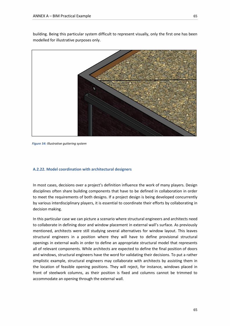
ANNEX A – BIM Practical Example 65
65
building. Being this particular system difficult to represent visually, only the first one has been
modelled for illustrative purposes only.
A.2.22. Model coordination with architectural designers
In most cases, decisions over a project’s definition influence the work of many players. Design
disciplines often share building components that have to be defined in collaboration in order
to meet the requirements of both designs. If a project design is being developed concurrently
by various interdisciplinary players, it is essential to coordinate their efforts by collaborating in
decision making.
In this particular case we can picture a scenario where structural engineers and architects need
to collaborate in defining door and window placement in external wall’s surface. As previously
mentioned, architects were still studying several alternatives for window layout. This leaves
structural engineers in a position where they will have to define provisional structural
openings in external walls in order to define an appropriate structural model that represents
all of relevant components. While architects are expected to define the final position of doors
and windows, structural engineers have the word for validating their decisions. To put a rather
simplistic example, structural engineers may collaborate with architects by assisting them in
the location of feasible opening positions. They will reject, for instance, windows placed in
front of steelwork columns, as their position is fixed and columns cannot be trimmed to
accommodate an opening through the external wall.
Figure 54: Illustrative guttering system
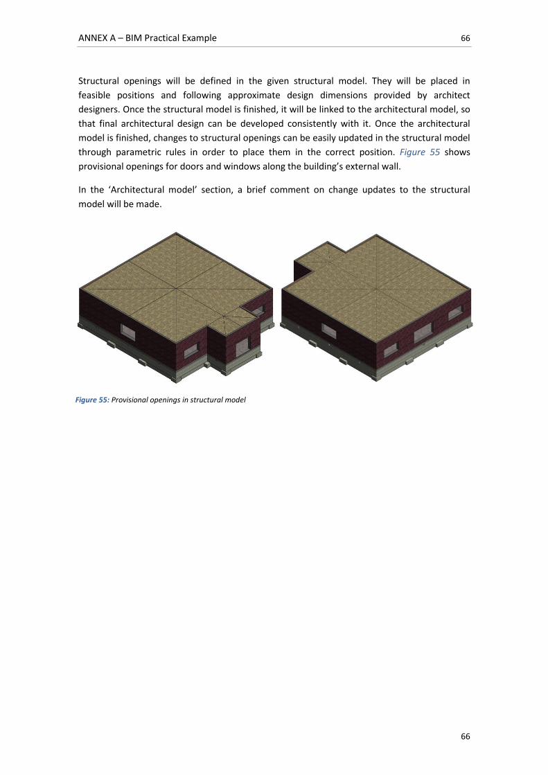
ANNEX A – BIM Practical Example 66
66
Structural openings will be defined in the given structural model. They will be placed in
feasible positions and following approximate design dimensions provided by architect
designers. Once the structural model is finished, it will be linked to the architectural model, so
that final architectural design can be developed consistently with it. Once the architectural
model is finished, changes to structural openings can be easily updated in the structural model
through parametric rules in order to place them in the correct position. Figure 55 shows
provisional openings for doors and windows along the building’s external wall.
In the ‘Architectural model’ section, a brief comment on change updates to the structural
model will be made.
Figure 55: Provisional openings in structural model
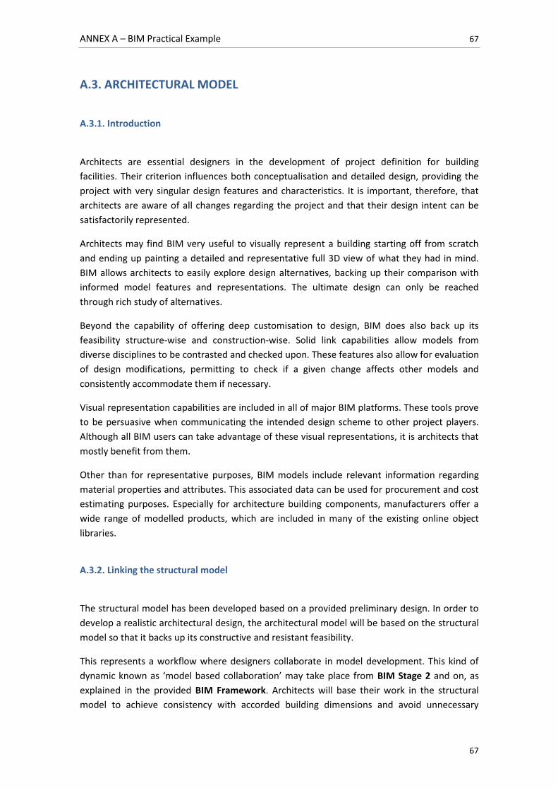
ANNEX A – BIM Practical Example 67
67
A.3. ARCHITECTURAL MODEL
A.3.1. Introduction
Architects are essential designers in the development of project definition for building
facilities. Their criterion influences both conceptualisation and detailed design, providing the
project with very singular design features and characteristics. It is important, therefore, that
architects are aware of all changes regarding the project and that their design intent can be
satisfactorily represented.
Architects may find BIM very useful to visually represent a building starting off from scratch
and ending up painting a detailed and representative full 3D view of what they had in mind.
BIM allows architects to easily explore design alternatives, backing up their comparison with
informed model features and representations. The ultimate design can only be reached
through rich study of alternatives.
Beyond the capability of offering deep customisation to design, BIM does also back up its
feasibility structure-wise and construction-wise. Solid link capabilities allow models from
diverse disciplines to be contrasted and checked upon. These features also allow for evaluation
of design modifications, permitting to check if a given change affects other models and
consistently accommodate them if necessary.
Visual representation capabilities are included in all of major BIM platforms. These tools prove
to be persuasive when communicating the intended design scheme to other project players.
Although all BIM users can take advantage of these visual representations, it is architects that
mostly benefit from them.
Other than for representative purposes, BIM models include relevant information regarding
material properties and attributes. This associated data can be used for procurement and cost
estimating purposes. Especially for architecture building components, manufacturers offer a
wide range of modelled products, which are included in many of the existing online object
libraries.
A.3.2. Linking the structural model
The structural model has been developed based on a provided preliminary design. In order to
develop a realistic architectural design, the architectural model will be based on the structural
model so that it backs up its constructive and resistant feasibility.
This represents a workflow where designers collaborate in model development. This kind of
dynamic known as ‘model based collaboration’ may take place from BIM Stage 2 and on, as
explained in the provided BIM Framework. Architects will base their work in the structural
model to achieve consistency with accorded building dimensions and avoid unnecessary
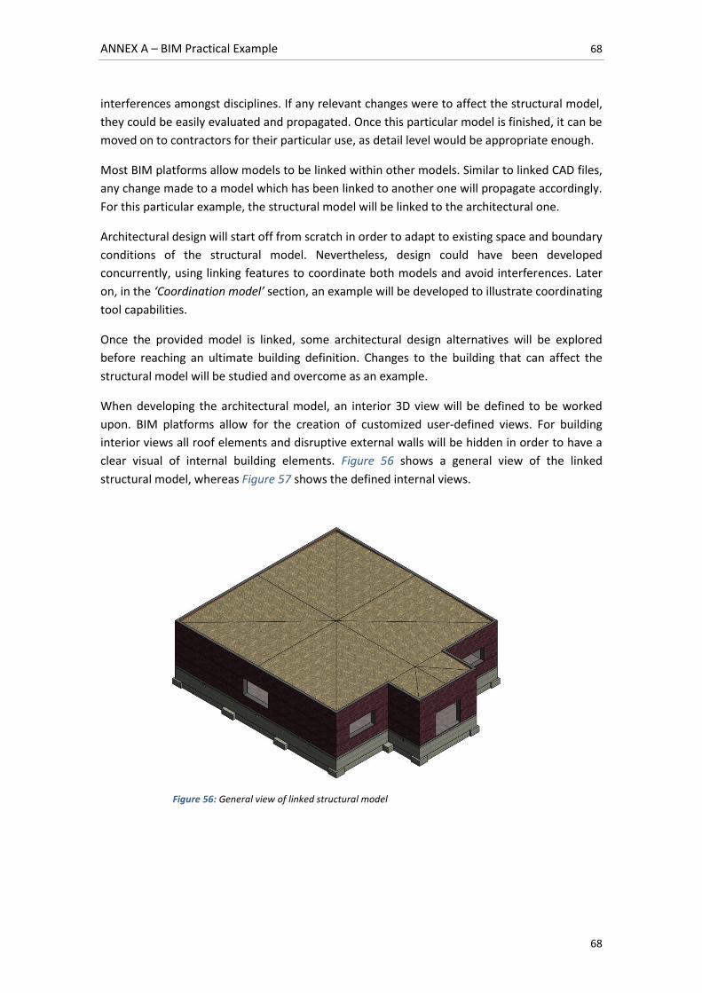
ANNEX A – BIM Practical Example 68
68
interferences amongst disciplines. If any relevant changes were to affect the structural model,
they could be easily evaluated and propagated. Once this particular model is finished, it can be
moved on to contractors for their particular use, as detail level would be appropriate enough.
Most BIM platforms allow models to be linked within other models. Similar to linked CAD files,
any change made to a model which has been linked to another one will propagate accordingly.
For this particular example, the structural model will be linked to the architectural one.
Architectural design will start off from scratch in order to adapt to existing space and boundary
conditions of the structural model. Nevertheless, design could have been developed
concurrently, using linking features to coordinate both models and avoid interferences. Later
on, in the ‘Coordination model’ section, an example will be developed to illustrate coordinating
tool capabilities.
Once the provided model is linked, some architectural design alternatives will be explored
before reaching an ultimate building definition. Changes to the building that can affect the
structural model will be studied and overcome as an example.
When developing the architectural model, an interior 3D view will be defined to be worked
upon. BIM platforms allow for the creation of customized user-defined views. For building
interior views all roof elements and disruptive external walls will be hidden in order to have a
clear visual of internal building elements. Figure 56 shows a general view of the linked
structural model, whereas Figure 57 shows the defined internal views.
Figure 56: General view of linked structural model
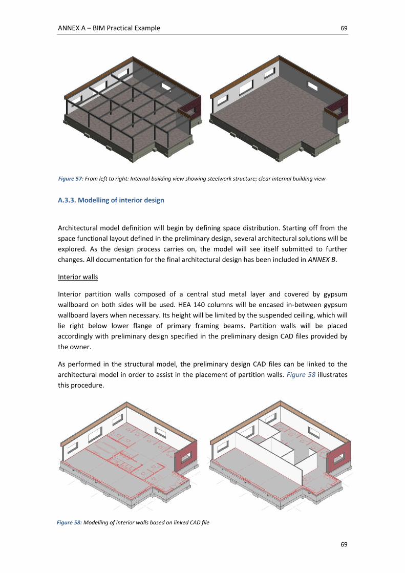
ANNEX A – BIM Practical Example 69
69
A.3.3. Modelling of interior design
Architectural model definition will begin by defining space distribution. Starting off from the
space functional layout defined in the preliminary design, several architectural solutions will be
explored. As the design process carries on, the model will see itself submitted to further
changes. All documentation for the final architectural design has been included in ANNEX B.
Interior walls
Interior partition walls composed of a central stud metal layer and covered by gypsum
wallboard on both sides will be used. HEA 140 columns will be encased in-between gypsum
wallboard layers when necessary. Its height will be limited by the suspended ceiling, which will
lie right below lower flange of primary framing beams. Partition walls will be placed
accordingly with preliminary design specified in the preliminary design CAD files provided by
the owner.
As performed in the structural model, the preliminary design CAD files can be linked to the
architectural model in order to assist in the placement of partition walls. Figure 58 illustrates
this procedure.
Figure 57: From left to right: Internal building view showing steelwork structure; clear internal building view
Figure 58: Modelling of interior walls based on linked CAD file
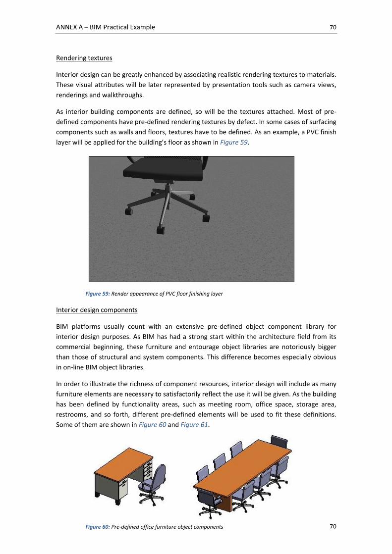
ANNEX A – BIM Practical Example 70
70
Rendering textures
Interior design can be greatly enhanced by associating realistic rendering textures to materials.
These visual attributes will be later represented by presentation tools such as camera views,
renderings and walkthroughs.
As interior building components are defined, so will be the textures attached. Most of pre-
defined components have pre-defined rendering textures by defect. In some cases of surfacing
components such as walls and floors, textures have to be defined. As an example, a PVC finish
layer will be applied for the building’s floor as shown in Figure 59.
Interior design components
BIM platforms usually count with an extensive pre-defined object component library for
interior design purposes. As BIM has had a strong start within the architecture field from its
commercial beginning, these furniture and entourage object libraries are notoriously bigger
than those of structural and system components. This difference becomes especially obvious
in on-line BIM object libraries.
In order to illustrate the richness of component resources, interior design will include as many
furniture elements are necessary to satisfactorily reflect the use it will be given. As the building
has been defined by functionality areas, such as meeting room, office space, storage area,
restrooms, and so forth, different pre-defined elements will be used to fit these definitions.
Some of them are shown in Figure 60 and Figure 61.
Figure 59: Render appearance of PVC floor finishing layer
Figure 60: Pre-defined office furniture object components
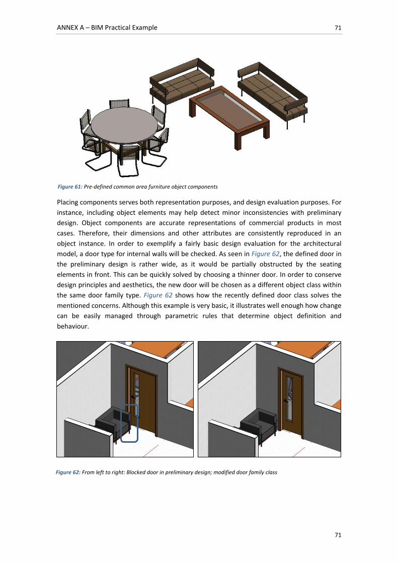
ANNEX A – BIM Practical Example 71
71
Placing components serves both representation purposes, and design evaluation purposes. For
instance, including object elements may help detect minor inconsistencies with preliminary
design. Object components are accurate representations of commercial products in most
cases. Therefore, their dimensions and other attributes are consistently reproduced in an
object instance. In order to exemplify a fairly basic design evaluation for the architectural
model, a door type for internal walls will be checked. As seen in Figure 62, the defined door in
the preliminary design is rather wide, as it would be partially obstructed by the seating
elements in front. This can be quickly solved by choosing a thinner door. In order to conserve
design principles and aesthetics, the new door will be chosen as a different object class within
the same door family type. Figure 62 shows how the recently defined door class solves the
mentioned concerns. Although this example is very basic, it illustrates well enough how change
can be easily managed through parametric rules that determine object definition and
behaviour.
Figure 61: Pre-defined common area furniture object components
Figure 62: From left to right: Blocked door in preliminary design; modified door family class
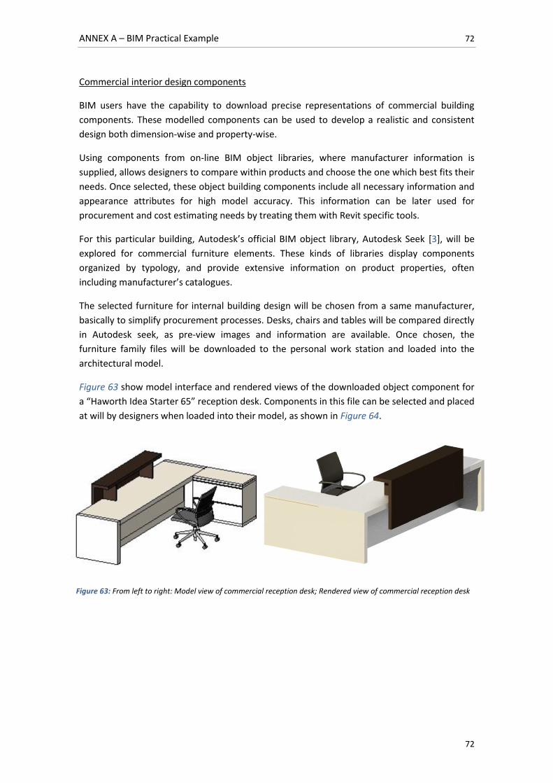
ANNEX A – BIM Practical Example 72
72
Commercial interior design components
BIM users have the capability to download precise representations of commercial building
components. These modelled components can be used to develop a realistic and consistent
design both dimension-wise and property-wise.
Using components from on-line BIM object libraries, where manufacturer information is
supplied, allows designers to compare within products and choose the one which best fits their
needs. Once selected, these object building components include all necessary information and
appearance attributes for high model accuracy. This information can be later used for
procurement and cost estimating needs by treating them with Revit specific tools.
For this particular building, Autodesk’s official BIM object library, Autodesk Seek [3], will be
explored for commercial furniture elements. These kinds of libraries display components
organized by typology, and provide extensive information on product properties, often
including manufacturer’s catalogues.
The selected furniture for internal building design will be chosen from a same manufacturer,
basically to simplify procurement processes. Desks, chairs and tables will be compared directly
in Autodesk seek, as pre-view images and information are available. Once chosen, the
furniture family files will be downloaded to the personal work station and loaded into the
architectural model.
Figure 63 show model interface and rendered views of the downloaded object component for
a “Haworth Idea Starter 65” reception desk. Components in this file can be selected and placed
at will by designers when loaded into their model, as shown in Figure 64.
Figure 63: From left to right: Model view of commercial reception desk; Rendered view of commercial reception desk
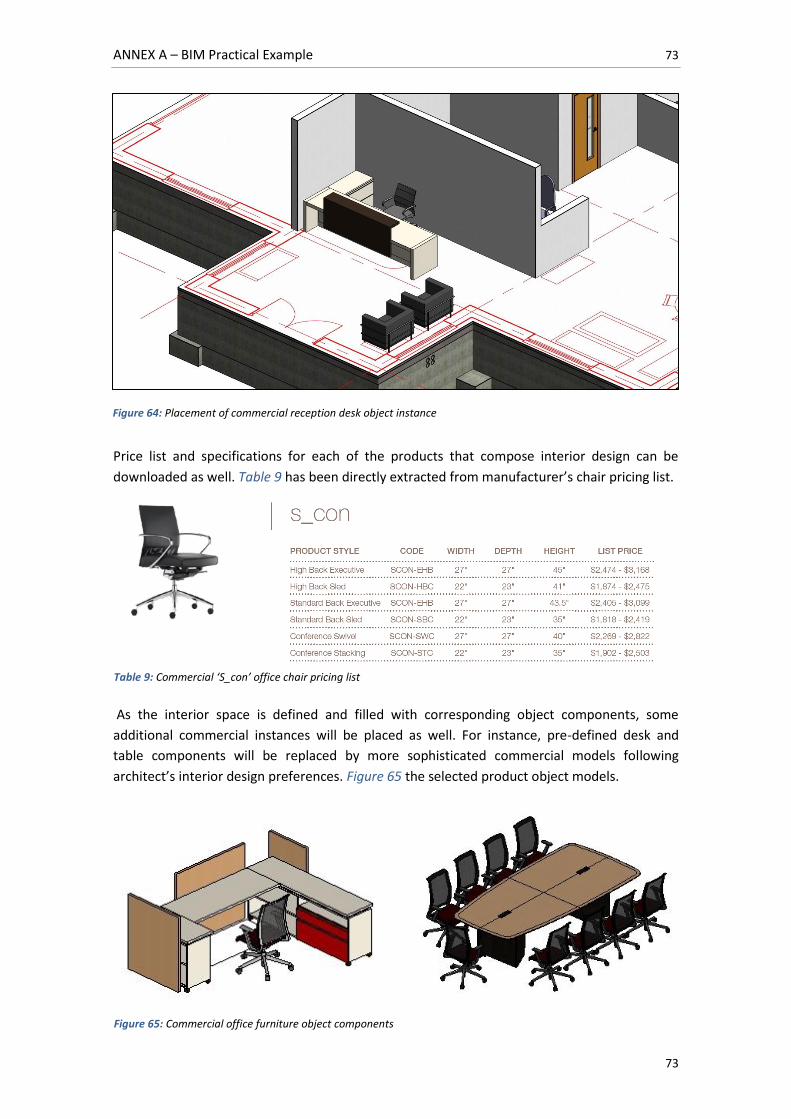
ANNEX A – BIM Practical Example 73
73
Price list and specifications for each of the products that compose interior design can be
downloaded as well. Table 9 has been directly extracted from manufacturer’s chair pricing list.
As the interior space is defined and filled with corresponding object components, some
additional commercial instances will be placed as well. For instance, pre-defined desk and
table components will be replaced by more sophisticated commercial models following
architect’s interior design preferences. Figure 65 the selected product object models.
Figure 64: Placement of commercial reception desk object instance
Table 9: Commercial ‘S_con’ office chair pricing list
Figure 65: Commercial office furniture object components
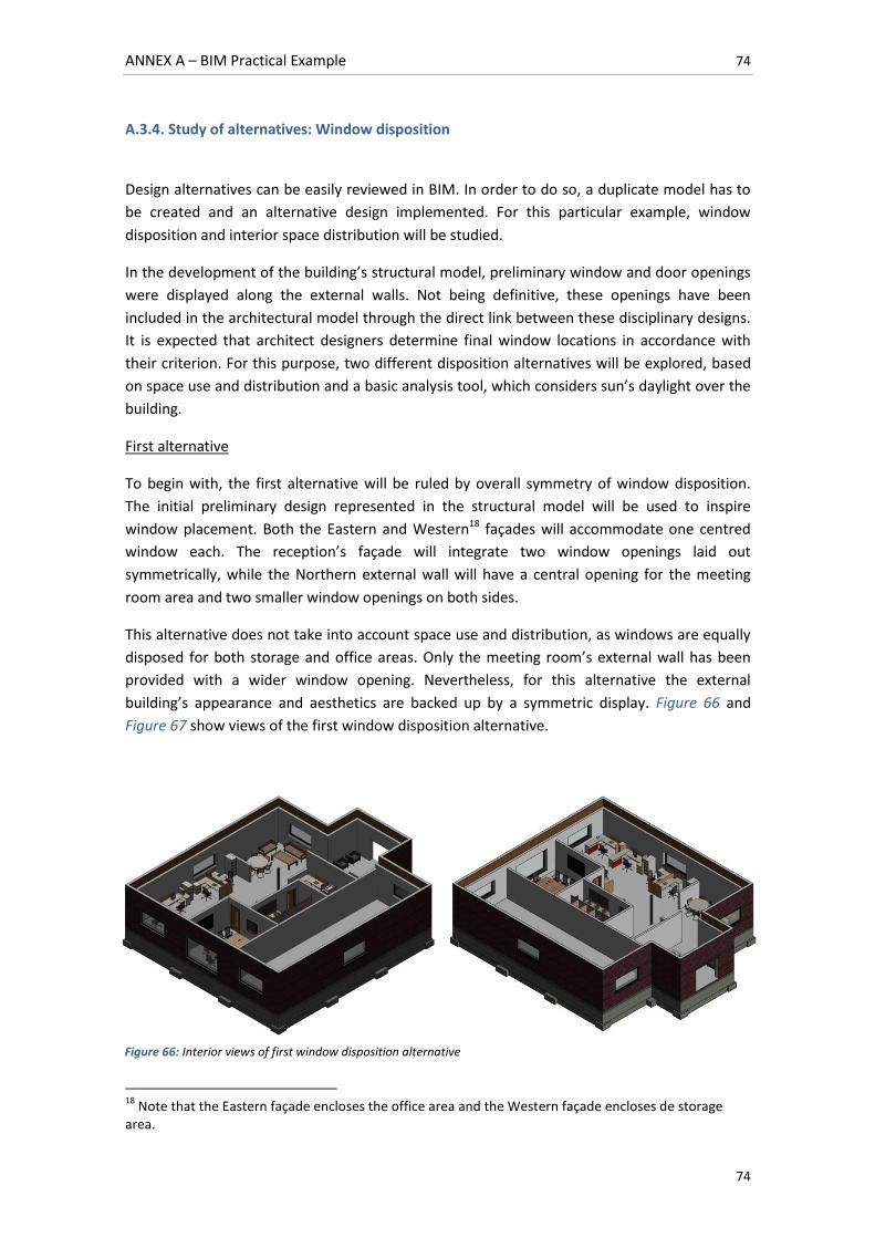
ANNEX A – BIM Practical Example 74
74
A.3.4. Study of alternatives: Window disposition
Design alternatives can be easily reviewed in BIM. In order to do so, a duplicate model has to
be created and an alternative design implemented. For this particular example, window
disposition and interior space distribution will be studied.
In the development of the building’s structural model, preliminary window and door openings
were displayed along the external walls. Not being definitive, these openings have been
included in the architectural model through the direct link between these disciplinary designs.
It is expected that architect designers determine final window locations in accordance with
their criterion. For this purpose, two different disposition alternatives will be explored, based
on space use and distribution and a basic analysis tool, which considers sun’s daylight over the
building.
First alternative
To begin with, the first alternative will be ruled by overall symmetry of window disposition.
The initial preliminary design represented in the structural model will be used to inspire
window placement. Both the Eastern and Western18 façades will accommodate one centred
window each. The reception’s façade will integrate two window openings laid out
symmetrically, while the Northern external wall will have a central opening for the meeting
room area and two smaller window openings on both sides.
This alternative does not take into account space use and distribution, as windows are equally
disposed for both storage and office areas. Only the meeting room’s external wall has been
provided with a wider window opening. Nevertheless, for this alternative the external
building’s appearance and aesthetics are backed up by a symmetric display. Figure 66 and
Figure 67 show views of the first window disposition alternative.
18
Note that the Eastern façade encloses the office area and the Western façade encloses de storage area.
Figure 66: Interior views of first window disposition alternative
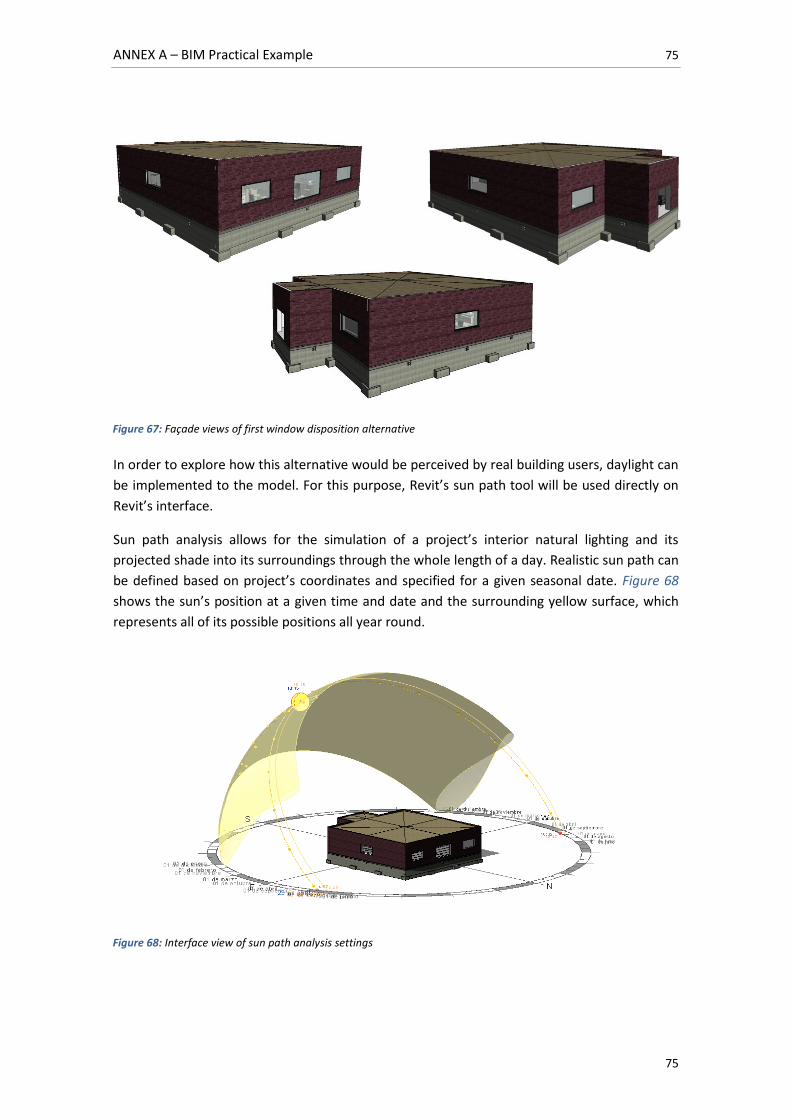
ANNEX A – BIM Practical Example 75
75
In order to explore how this alternative would be perceived by real building users, daylight can
be implemented to the model. For this purpose, Revit’s sun path tool will be used directly on
Revit’s interface.
Sun path analysis allows for the simulation of a project’s interior natural lighting and its
projected shade into its surroundings through the whole length of a day. Realistic sun path can
be defined based on project’s coordinates and specified for a given seasonal date. Figure 68
shows the sun’s position at a given time and date and the surrounding yellow surface, which
represents all of its possible positions all year round.
Figure 67: Façade views of first window disposition alternative
Figure 68: Interface view of sun path analysis settings
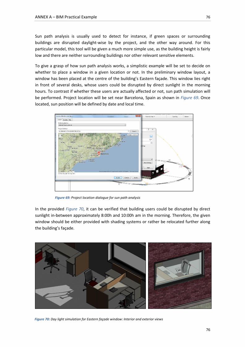
ANNEX A – BIM Practical Example 76
76
Sun path analysis is usually used to detect for instance, if green spaces or surrounding
buildings are disrupted daylight-wise by the project, and the other way around. For this
particular model, this tool will be given a much more simple use, as the building height is fairly
low and there are neither surrounding buildings nor other relevant sensitive elements.
To give a grasp of how sun path analysis works, a simplistic example will be set to decide on
whether to place a window in a given location or not. In the preliminary window layout, a
window has been placed at the centre of the building’s Eastern façade. This window lies right
in front of several desks, whose users could be disrupted by direct sunlight in the morning
hours. To contrast if whether these users are actually affected or not, sun path simulation will
be performed. Project location will be set near Barcelona, Spain as shown in Figure 69. Once
located, sun position will be defined by date and local time.
In the provided Figure 70, it can be verified that building users could be disrupted by direct
sunlight in-between approximately 8:00h and 10:00h am in the morning. Therefore, the given
window should be either provided with shading systems or rather be relocated further along
the building’s façade.
Figure 69: Project location dialogue for sun path analysis
Figure 70: Day light simulation for Eastern façade window: Interior and exterior views
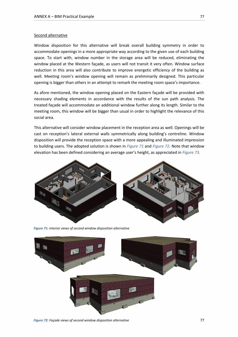
ANNEX A – BIM Practical Example 77
77
Second alternative
Window disposition for this alternative will break overall building symmetry in order to
accommodate openings in a more appropriate way according to the given use of each building
space. To start with, window number in the storage area will be reduced, eliminating the
window placed at the Western façade, as users will not transit it very often. Window surface
reduction in this area will also contribute to improve energetic efficiency of the building as
well. Meeting room’s window opening will remain as preliminarily designed. This particular
opening is bigger than others in an attempt to remark the meeting room space’s importance.
As afore mentioned, the window opening placed on the Eastern façade will be provided with
necessary shading elements in accordance with the results of the sun path analysis. The
treated façade will accommodate an additional window further along its length. Similar to the
meeting room, this window will be bigger than usual in order to highlight the relevance of this
social area.
This alternative will consider window placement in the reception area as well. Openings will be
cast on reception’s lateral external walls symmetrically along building’s centreline. Window
disposition will provide the reception space with a more appealing and illuminated impression
to building users. The adopted solution is shown in Figure 71 and Figure 72. Note that window
elevation has been defined considering an average user’s height, as appreciated in Figure 73.
Figure 71: Interior views of second window disposition alternative
Figure 72: Façade views of second window disposition alternative
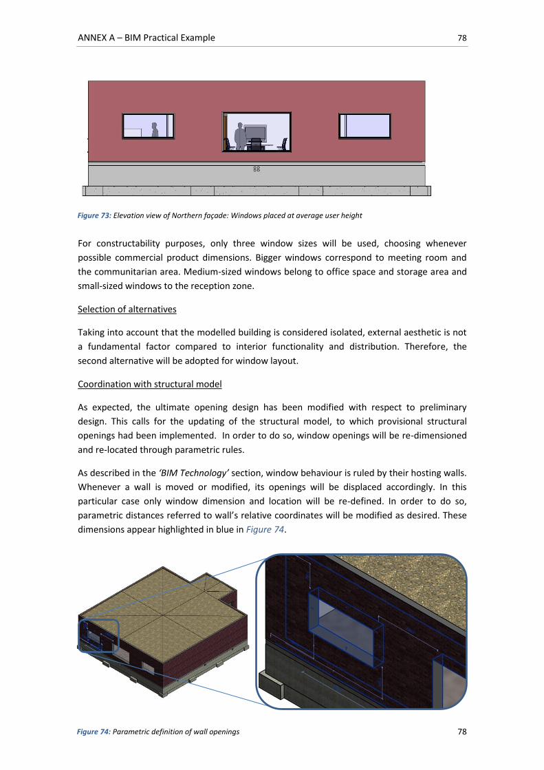
ANNEX A – BIM Practical Example 78
78
For constructability purposes, only three window sizes will be used, choosing whenever
possible commercial product dimensions. Bigger windows correspond to meeting room and
the communitarian area. Medium-sized windows belong to office space and storage area and
small-sized windows to the reception zone.
Selection of alternatives
Taking into account that the modelled building is considered isolated, external aesthetic is not
a fundamental factor compared to interior functionality and distribution. Therefore, the
second alternative will be adopted for window layout.
Coordination with structural model
As expected, the ultimate opening design has been modified with respect to preliminary
design. This calls for the updating of the structural model, to which provisional structural
openings had been implemented. In order to do so, window openings will be re-dimensioned
and re-located through parametric rules.
As described in the ‘BIM Technology’ section, window behaviour is ruled by their hosting walls.
Whenever a wall is moved or modified, its openings will be displaced accordingly. In this
particular case only window dimension and location will be re-defined. In order to do so,
parametric distances referred to wall’s relative coordinates will be modified as desired. These
dimensions appear highlighted in blue in Figure 74.
Figure 73: Elevation view of Northern façade: Windows placed at average user height
Figure 74: Parametric definition of wall openings
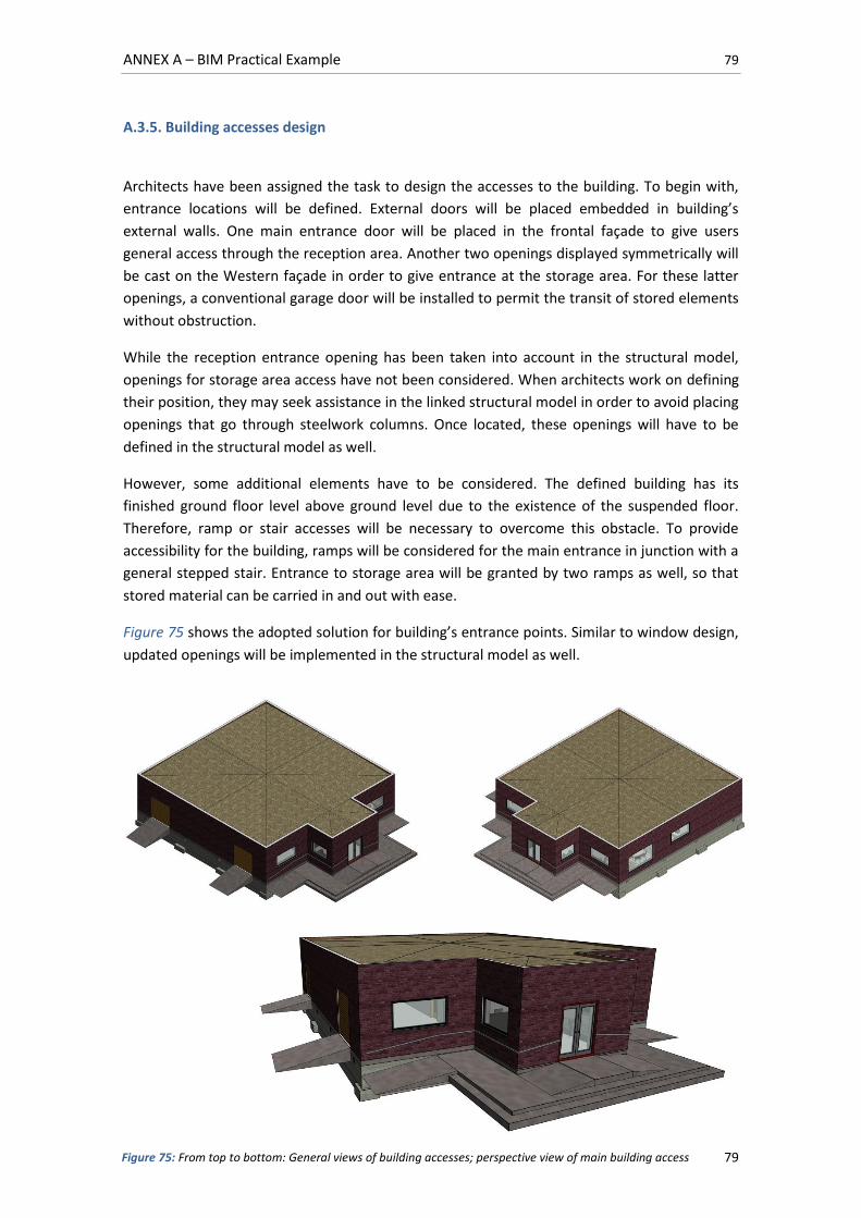
ANNEX A – BIM Practical Example 79
79
A.3.5. Building accesses design
Architects have been assigned the task to design the accesses to the building. To begin with,
entrance locations will be defined. External doors will be placed embedded in building’s
external walls. One main entrance door will be placed in the frontal façade to give users
general access through the reception area. Another two openings displayed symmetrically will
be cast on the Western façade in order to give entrance at the storage area. For these latter
openings, a conventional garage door will be installed to permit the transit of stored elements
without obstruction.
While the reception entrance opening has been taken into account in the structural model,
openings for storage area access have not been considered. When architects work on defining
their position, they may seek assistance in the linked structural model in order to avoid placing
openings that go through steelwork columns. Once located, these openings will have to be
defined in the structural model as well.
However, some additional elements have to be considered. The defined building has its
finished ground floor level above ground level due to the existence of the suspended floor.
Therefore, ramp or stair accesses will be necessary to overcome this obstacle. To provide
accessibility for the building, ramps will be considered for the main entrance in junction with a
general stepped stair. Entrance to storage area will be granted by two ramps as well, so that
stored material can be carried in and out with ease.
Figure 75 shows the adopted solution for building’s entrance points. Similar to window design,
updated openings will be implemented in the structural model as well.
Figure 75: From top to bottom: General views of building accesses; perspective view of main building access
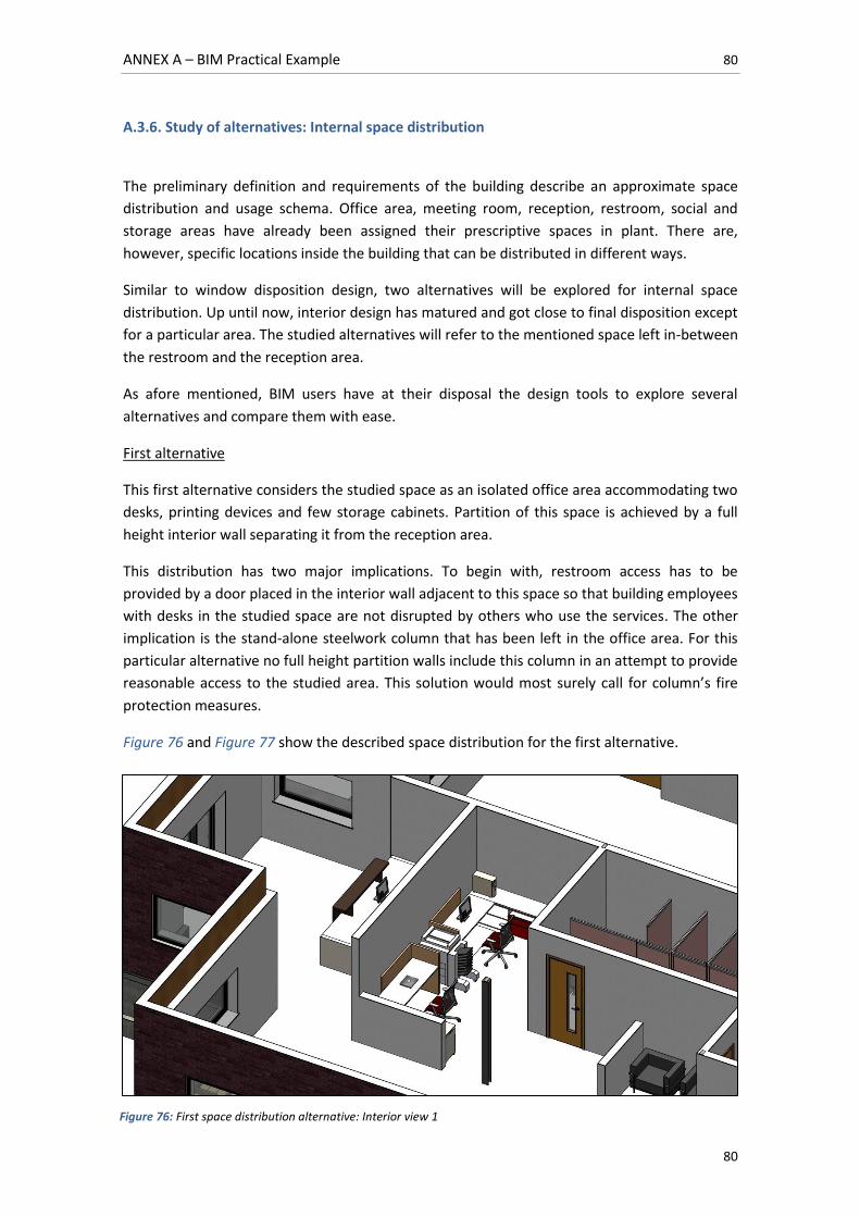
ANNEX A – BIM Practical Example 80
80
A.3.6. Study of alternatives: Internal space distribution
The preliminary definition and requirements of the building describe an approximate space
distribution and usage schema. Office area, meeting room, reception, restroom, social and
storage areas have already been assigned their prescriptive spaces in plant. There are,
however, specific locations inside the building that can be distributed in different ways.
Similar to window disposition design, two alternatives will be explored for internal space
distribution. Up until now, interior design has matured and got close to final disposition except
for a particular area. The studied alternatives will refer to the mentioned space left in-between
the restroom and the reception area.
As afore mentioned, BIM users have at their disposal the design tools to explore several
alternatives and compare them with ease.
First alternative
This first alternative considers the studied space as an isolated office area accommodating two
desks, printing devices and few storage cabinets. Partition of this space is achieved by a full
height interior wall separating it from the reception area.
This distribution has two major implications. To begin with, restroom access has to be
provided by a door placed in the interior wall adjacent to this space so that building employees
with desks in the studied space are not disrupted by others who use the services. The other
implication is the stand-alone steelwork column that has been left in the office area. For this
particular alternative no full height partition walls include this column in an attempt to provide
reasonable access to the studied area. This solution would most surely call for column’s fire
protection measures.
Figure 76 and Figure 77 show the described space distribution for the first alternative.
Figure 76: First space distribution alternative: Interior view 1
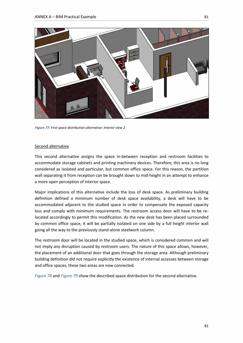
ANNEX A – BIM Practical Example 81
81
Second alternative
This second alternative assigns the space in-between reception and restroom facilities to
accommodate storage cabinets and printing machinery devices. Therefore, this area is no long
considered as isolated and particular, but common office space. For this reason, the partition
wall separating it from reception can be brought down to mid-height in an attempt to enhance
a more open perception of interior space.
Major implications of this alternative include the loss of desk space. As preliminary building
definition defined a minimum number of desk space availability, a desk will have to be
accommodated adjacent to the studied space in order to compensate the exposed capacity
loss and comply with minimum requirements. The restroom access door will have to be re-
located accordingly to permit this modification. As the new desk has been placed surrounded
by common office space, it will be partially isolated on one side by a full height interior wall
going all the way to the previously stand-alone steelwork column.
The restroom door will be located in the studied space, which is considered common and will
not imply any disruption caused by restroom users. The nature of this space allows, however,
the placement of an additional door that goes through the storage area. Although preliminary
building definition did not require explicitly the existence of internal accesses between storage
and office spaces, these two areas are now connected.
Figure 78 and Figure 79 show the described space distribution for the second alternative.
Figure 77: First space distribution alternative: Interior view 2
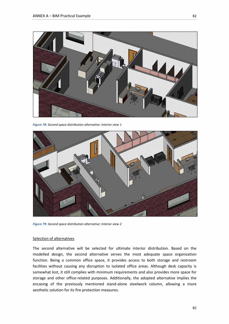
ANNEX A – BIM Practical Example 82
82
Figure 78: Second space distribution alternative: Interior view 1
Figure 79: Second space distribution alternative: Interior view 2
Selection of alternatives
The second alternative will be selected for ultimate interior distribution. Based on the
modelled design, the second alternative serves the most adequate space organization
function. Being a common office space, it provides access to both storage and restroom
facilities without causing any disruption to isolated office areas. Although desk capacity is
somewhat lost, it still complies with minimum requirements and also provides more space for
storage and other office-related purposes. Additionally, the adopted alternative implies the
encasing of the previously mentioned stand-alone steelwork column, allowing a more
aesthetic solution for its fire protection measures.
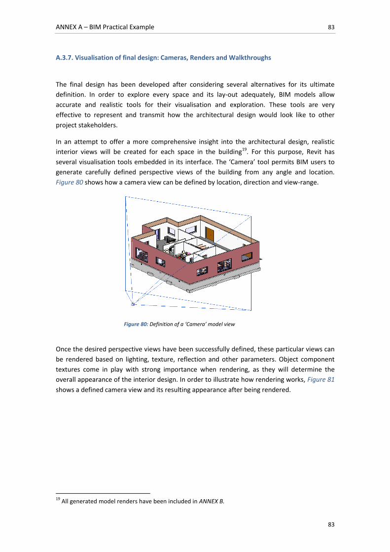
ANNEX A – BIM Practical Example 83
83
A.3.7. Visualisation of final design: Cameras, Renders and Walkthroughs
The final design has been developed after considering several alternatives for its ultimate
definition. In order to explore every space and its lay-out adequately, BIM models allow
accurate and realistic tools for their visualisation and exploration. These tools are very
effective to represent and transmit how the architectural design would look like to other
project stakeholders.
In an attempt to offer a more comprehensive insight into the architectural design, realistic
interior views will be created for each space in the building19. For this purpose, Revit has
several visualisation tools embedded in its interface. The ‘Camera’ tool permits BIM users to
generate carefully defined perspective views of the building from any angle and location.
Figure 80 shows how a camera view can be defined by location, direction and view-range.
Once the desired perspective views have been successfully defined, these particular views can
be rendered based on lighting, texture, reflection and other parameters. Object component
textures come in play with strong importance when rendering, as they will determine the
overall appearance of the interior design. In order to illustrate how rendering works, Figure 81
shows a defined camera view and its resulting appearance after being rendered.
19
All generated model renders have been included in ANNEX B.
Figure 80: Definition of a ‘Camera’ model view
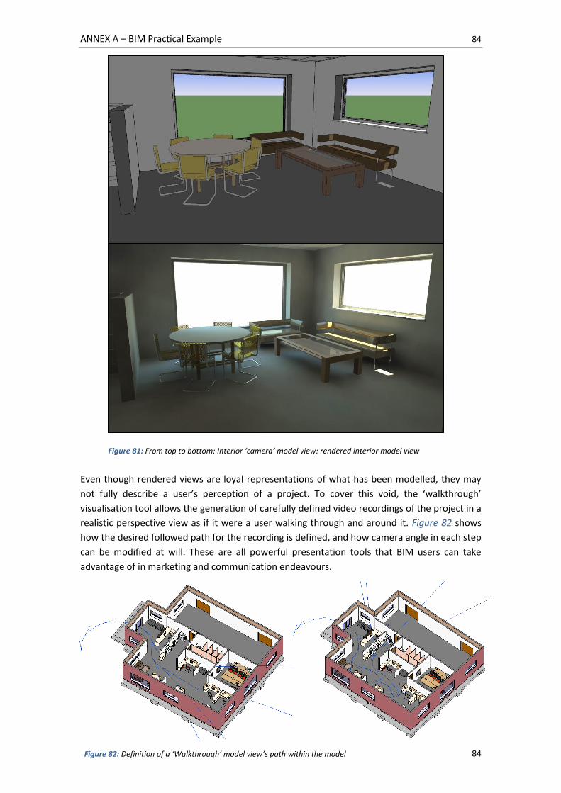
ANNEX A – BIM Practical Example 84
84
Even though rendered views are loyal representations of what has been modelled, they may
not fully describe a user’s perception of a project. To cover this void, the ‘walkthrough’
visualisation tool allows the generation of carefully defined video recordings of the project in a
realistic perspective view as if it were a user walking through and around it. Figure 82 shows
how the desired followed path for the recording is defined, and how camera angle in each step
can be modified at will. These are all powerful presentation tools that BIM users can take
advantage of in marketing and communication endeavours.
Figure 82: Definition of a ‘Walkthrough’ model view’s path within the model
Figure 81: From top to bottom: Interior ‘camera’ model view; rendered interior model view
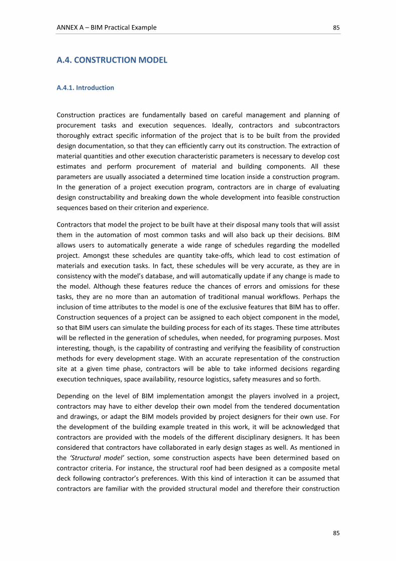
ANNEX A – BIM Practical Example 85
85
A.4. CONSTRUCTION MODEL
A.4.1. Introduction
Construction practices are fundamentally based on careful management and planning of
procurement tasks and execution sequences. Ideally, contractors and subcontractors
thoroughly extract specific information of the project that is to be built from the provided
design documentation, so that they can efficiently carry out its construction. The extraction of
material quantities and other execution characteristic parameters is necessary to develop cost
estimates and perform procurement of material and building components. All these
parameters are usually associated a determined time location inside a construction program.
In the generation of a project execution program, contractors are in charge of evaluating
design constructability and breaking down the whole development into feasible construction
sequences based on their criterion and experience.
Contractors that model the project to be built have at their disposal many tools that will assist
them in the automation of most common tasks and will also back up their decisions. BIM
allows users to automatically generate a wide range of schedules regarding the modelled
project. Amongst these schedules are quantity take-offs, which lead to cost estimation of
materials and execution tasks. In fact, these schedules will be very accurate, as they are in
consistency with the model’s database, and will automatically update if any change is made to
the model. Although these features reduce the chances of errors and omissions for these
tasks, they are no more than an automation of traditional manual workflows. Perhaps the
inclusion of time attributes to the model is one of the exclusive features that BIM has to offer.
Construction sequences of a project can be assigned to each object component in the model,
so that BIM users can simulate the building process for each of its stages. These time attributes
will be reflected in the generation of schedules, when needed, for programing purposes. Most
interesting, though, is the capability of contrasting and verifying the feasibility of construction
methods for every development stage. With an accurate representation of the construction
site at a given time phase, contractors will be able to take informed decisions regarding
execution techniques, space availability, resource logistics, safety measures and so forth.
Depending on the level of BIM implementation amongst the players involved in a project,
contractors may have to either develop their own model from the tendered documentation
and drawings, or adapt the BIM models provided by project designers for their own use. For
the development of the building example treated in this work, it will be acknowledged that
contractors are provided with the models of the different disciplinary designers. It has been
considered that contractors have collaborated in early design stages as well. As mentioned in
the ‘Structural model’ section, some construction aspects have been determined based on
contractor criteria. For instance, the structural roof had been designed as a composite metal
deck following contractor’s preferences. With this kind of interaction it can be assumed that
contractors are familiar with the provided structural model and therefore their construction
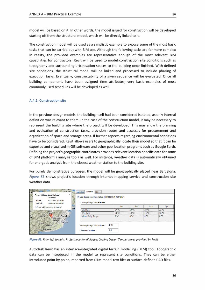
ANNEX A – BIM Practical Example 86
86
model will be based on it. In other words, the model issued for construction will be developed
starting off from the structural model, which will be directly linked to it.
The construction model will be used as a simplistic example to expose some of the most basic
tasks that can be carried out with BIM use. Although the following tasks are far more complex
in reality, the provided examples are representative enough of the most relevant BIM
capabilities for contractors. Revit will be used to model construction site conditions such as
topography and surrounding urbanisation spaces to the building once finished. With defined
site conditions, the structural model will be linked and processed to include phasing of
execution tasks. Eventually, constructability of a given sequence will be evaluated. Once all
building components have been assigned time attributes, very basic examples of most
commonly used schedules will be developed as well.
A.4.2. Construction site
In the previous design models, the building itself had been considered isolated, as only internal
definition was relevant to them. In the case of the construction model, it may be necessary to
represent the building site where the project will be developed. This may allow the planning
and evaluation of construction tasks, provision routes and accesses for procurement and
organization of space and storage areas. If further aspects regarding environmental conditions
have to be considered, Revit allows users to geographically locate their model so that it can be
exported and visualised in GIS software and other geo-location programs such as Google Earth.
Defining the project’s geographic coordinates provides relevant location-specific data for some
of BIM platform’s analysis tools as well. For instance, weather data is automatically obtained
for energetic analysis from the closest weather station to the building site.
For purely demonstrative purposes, the model will be geographically placed near Barcelona.
Figure 83 shows project’s location through internet mapping service and construction site
weather data.
Autodesk Revit has an interface-integrated digital terrain modelling (DTM) tool. Topographic
data can be introduced in the model to represent site conditions. They can be either
introduced point by point, imported from DTM model text files or surface-defined CAD files.
Figure 83: From left to right: Project location dialogue; Cooling Design Temperatures provided by Revit
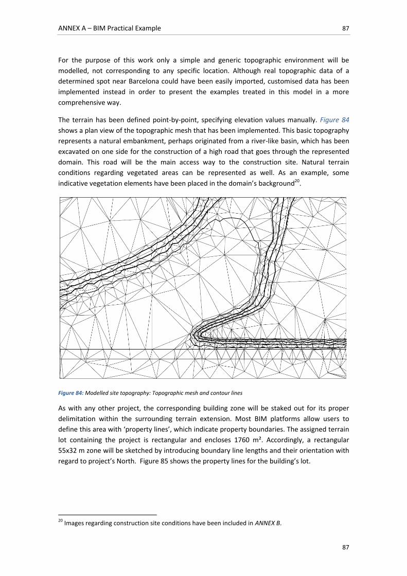
ANNEX A – BIM Practical Example 87
87
For the purpose of this work only a simple and generic topographic environment will be
modelled, not corresponding to any specific location. Although real topographic data of a
determined spot near Barcelona could have been easily imported, customised data has been
implemented instead in order to present the examples treated in this model in a more
comprehensive way.
The terrain has been defined point-by-point, specifying elevation values manually. Figure 84
shows a plan view of the topographic mesh that has been implemented. This basic topography
represents a natural embankment, perhaps originated from a river-like basin, which has been
excavated on one side for the construction of a high road that goes through the represented
domain. This road will be the main access way to the construction site. Natural terrain
conditions regarding vegetated areas can be represented as well. As an example, some
indicative vegetation elements have been placed in the domain’s background20.
Figure 84: Modelled site topography: Topographic mesh and contour lines
As with any other project, the corresponding building zone will be staked out for its proper
delimitation within the surrounding terrain extension. Most BIM platforms allow users to
define this area with ‘property lines’, which indicate property boundaries. The assigned terrain
lot containing the project is rectangular and encloses 1760 m². Accordingly, a rectangular
55x32 m zone will be sketched by introducing boundary line lengths and their orientation with
regard to project’s North. Figure 85 shows the property lines for the building’s lot.
20
Images regarding construction site conditions have been included in ANNEX B.
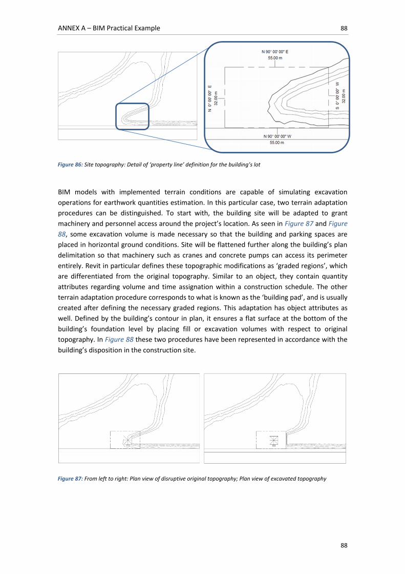
ANNEX A – BIM Practical Example 88
88
BIM models with implemented terrain conditions are capable of simulating excavation
operations for earthwork quantities estimation. In this particular case, two terrain adaptation
procedures can be distinguished. To start with, the building site will be adapted to grant
machinery and personnel access around the project’s location. As seen in Figure 87 and Figure
88, some excavation volume is made necessary so that the building and parking spaces are
placed in horizontal ground conditions. Site will be flattened further along the building’s plan
delimitation so that machinery such as cranes and concrete pumps can access its perimeter
entirely. Revit in particular defines these topographic modifications as ‘graded regions’, which
are differentiated from the original topography. Similar to an object, they contain quantity
attributes regarding volume and time assignation within a construction schedule. The other
terrain adaptation procedure corresponds to what is known as the ‘building pad’, and is usually
created after defining the necessary graded regions. This adaptation has object attributes as
well. Defined by the building’s contour in plan, it ensures a flat surface at the bottom of the
building’s foundation level by placing fill or excavation volumes with respect to original
topography. In Figure 88 these two procedures have been represented in accordance with the
building’s disposition in the construction site.
Figure 87: From left to right: Plan view of disruptive original topography; Plan view of excavated topography
Figure 86: Site topography: Detail of ‘property line’ definition for the building’s lot
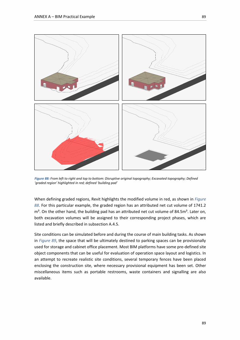
ANNEX A – BIM Practical Example 89
89
When defining graded regions, Revit highlights the modified volume in red, as shown in Figure
88. For this particular example, the graded region has an attributed net cut volume of 1741.2
m³. On the other hand, the building pad has an attributed net cut volume of 84.5m³. Later on,
both excavation volumes will be assigned to their corresponding project phases, which are
listed and briefly described in subsection A.4.5.
Site conditions can be simulated before and during the course of main building tasks. As shown
in Figure 89, the space that will be ultimately destined to parking spaces can be provisionally
used for storage and cabinet office placement. Most BIM platforms have some pre-defined site
object components that can be useful for evaluation of operation space layout and logistics. In
an attempt to recreate realistic site conditions, several temporary fences have been placed
enclosing the construction site, where necessary provisional equipment has been set. Other
miscellaneous items such as portable restrooms, waste containers and signalling are also
available.
Figure 88: From left to right and top to bottom: Disruptive original topography; Excavated topography; Defined ‘graded region’ highlighted in red; defined ‘building pad’
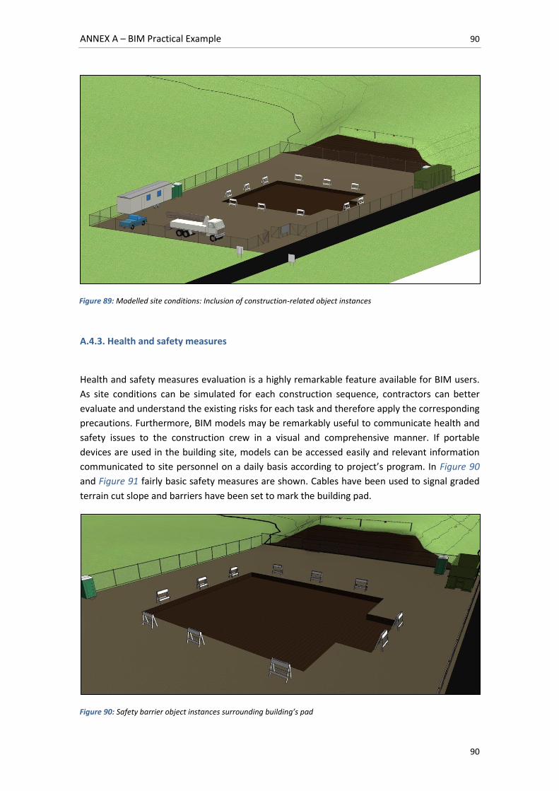
ANNEX A – BIM Practical Example 90
90
A.4.3. Health and safety measures
Health and safety measures evaluation is a highly remarkable feature available for BIM users.
As site conditions can be simulated for each construction sequence, contractors can better
evaluate and understand the existing risks for each task and therefore apply the corresponding
precautions. Furthermore, BIM models may be remarkably useful to communicate health and
safety issues to the construction crew in a visual and comprehensive manner. If portable
devices are used in the building site, models can be accessed easily and relevant information
communicated to site personnel on a daily basis according to project’s program. In Figure 90
and Figure 91 fairly basic safety measures are shown. Cables have been used to signal graded
terrain cut slope and barriers have been set to mark the building pad.
Figure 89: Modelled site conditions: Inclusion of construction-related object instances
Figure 90: Safety barrier object instances surrounding building’s pad
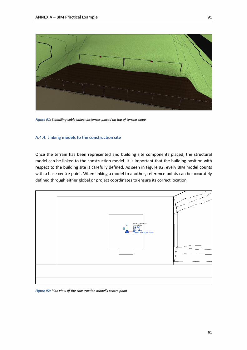
ANNEX A – BIM Practical Example 91
91
A.4.4. Linking models to the construction site
Once the terrain has been represented and building site components placed, the structural
model can be linked to the construction model. It is important that the building position with
respect to the building site is carefully defined. As seen in Figure 92, every BIM model counts
with a base centre point. When linking a model to another, reference points can be accurately
defined through either global or project coordinates to ensure its correct location.
Figure 92: Plan view of the construction model’s centre point
Figure 91: Signalling cable object instances placed on top of terrain slope
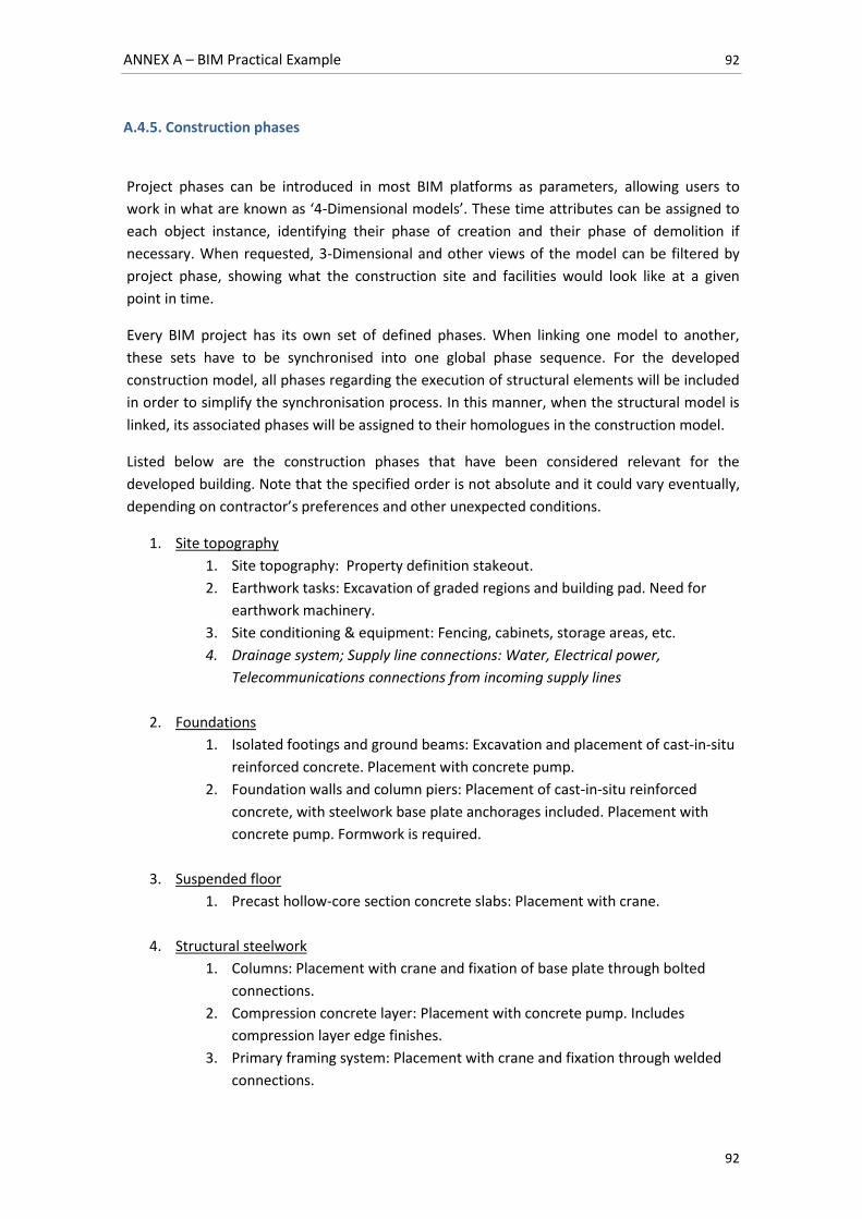
ANNEX A – BIM Practical Example 92
92
A.4.5. Construction phases
Project phases can be introduced in most BIM platforms as parameters, allowing users to
work in what are known as ‘4-Dimensional models’. These time attributes can be assigned to
each object instance, identifying their phase of creation and their phase of demolition if
necessary. When requested, 3-Dimensional and other views of the model can be filtered by
project phase, showing what the construction site and facilities would look like at a given
point in time.
Every BIM project has its own set of defined phases. When linking one model to another,
these sets have to be synchronised into one global phase sequence. For the developed
construction model, all phases regarding the execution of structural elements will be included
in order to simplify the synchronisation process. In this manner, when the structural model is
linked, its associated phases will be assigned to their homologues in the construction model.
Listed below are the construction phases that have been considered relevant for the
developed building. Note that the specified order is not absolute and it could vary eventually,
depending on contractor’s preferences and other unexpected conditions.
1. Site topography
1. Site topography: Property definition stakeout.
2. Earthwork tasks: Excavation of graded regions and building pad. Need for
earthwork machinery.
3. Site conditioning & equipment: Fencing, cabinets, storage areas, etc.
4. Drainage system; Supply line connections: Water, Electrical power,
Telecommunications connections from incoming supply lines
2. Foundations
1. Isolated footings and ground beams: Excavation and placement of cast-in-situ
reinforced concrete. Placement with concrete pump.
2. Foundation walls and column piers: Placement of cast-in-situ reinforced
concrete, with steelwork base plate anchorages included. Placement with
concrete pump. Formwork is required.
3. Suspended floor
1. Precast hollow-core section concrete slabs: Placement with crane.
4. Structural steelwork
1. Columns: Placement with crane and fixation of base plate through bolted
connections.
2. Compression concrete layer: Placement with concrete pump. Includes
compression layer edge finishes.
3. Primary framing system: Placement with crane and fixation through welded
connections.
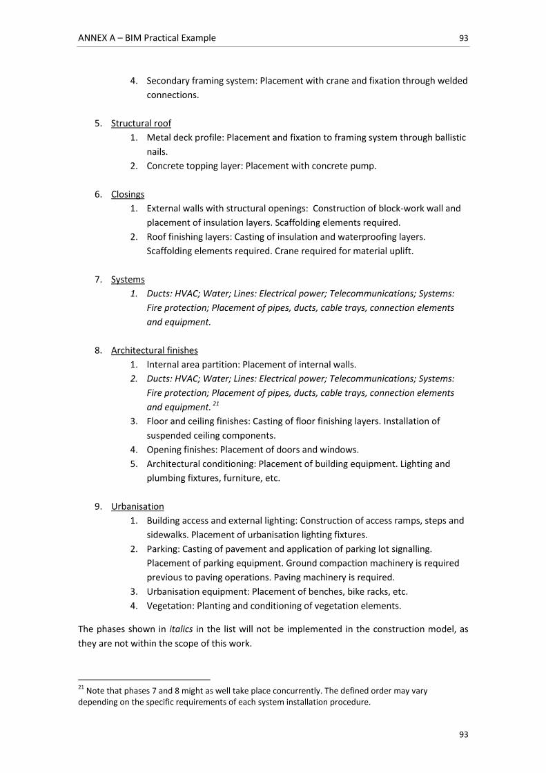
ANNEX A – BIM Practical Example 93
93
4. Secondary framing system: Placement with crane and fixation through welded
connections.
5. Structural roof
1. Metal deck profile: Placement and fixation to framing system through ballistic
nails.
2. Concrete topping layer: Placement with concrete pump.
6. Closings
1. External walls with structural openings: Construction of block-work wall and
placement of insulation layers. Scaffolding elements required.
2. Roof finishing layers: Casting of insulation and waterproofing layers.
Scaffolding elements required. Crane required for material uplift.
7. Systems
1. Ducts: HVAC; Water; Lines: Electrical power; Telecommunications; Systems:
Fire protection; Placement of pipes, ducts, cable trays, connection elements
and equipment.
8. Architectural finishes
1. Internal area partition: Placement of internal walls.
2. Ducts: HVAC; Water; Lines: Electrical power; Telecommunications; Systems:
Fire protection; Placement of pipes, ducts, cable trays, connection elements
and equipment. 21
3. Floor and ceiling finishes: Casting of floor finishing layers. Installation of
suspended ceiling components.
4. Opening finishes: Placement of doors and windows.
5. Architectural conditioning: Placement of building equipment. Lighting and
plumbing fixtures, furniture, etc.
9. Urbanisation
1. Building access and external lighting: Construction of access ramps, steps and
sidewalks. Placement of urbanisation lighting fixtures.
2. Parking: Casting of pavement and application of parking lot signalling.
Placement of parking equipment. Ground compaction machinery is required
previous to paving operations. Paving machinery is required.
3. Urbanisation equipment: Placement of benches, bike racks, etc.
4. Vegetation: Planting and conditioning of vegetation elements.
The phases shown in italics in the list will not be implemented in the construction model, as
they are not within the scope of this work.
21
Note that phases 7 and 8 might as well take place concurrently. The defined order may vary depending on the specific requirements of each system installation procedure.
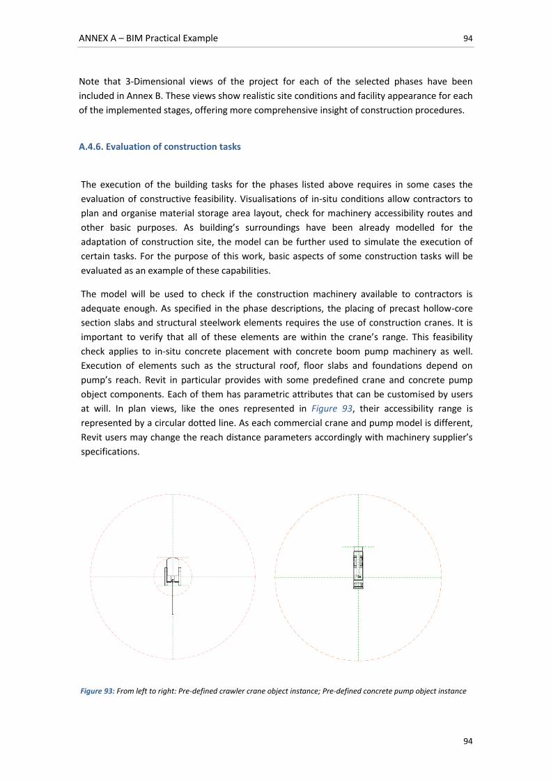
ANNEX A – BIM Practical Example 94
94
Note that 3-Dimensional views of the project for each of the selected phases have been
included in Annex B. These views show realistic site conditions and facility appearance for each
of the implemented stages, offering more comprehensive insight of construction procedures.
A.4.6. Evaluation of construction tasks
The execution of the building tasks for the phases listed above requires in some cases the
evaluation of constructive feasibility. Visualisations of in-situ conditions allow contractors to
plan and organise material storage area layout, check for machinery accessibility routes and
other basic purposes. As building’s surroundings have been already modelled for the
adaptation of construction site, the model can be further used to simulate the execution of
certain tasks. For the purpose of this work, basic aspects of some construction tasks will be
evaluated as an example of these capabilities.
The model will be used to check if the construction machinery available to contractors is
adequate enough. As specified in the phase descriptions, the placing of precast hollow-core
section slabs and structural steelwork elements requires the use of construction cranes. It is
important to verify that all of these elements are within the crane’s range. This feasibility
check applies to in-situ concrete placement with concrete boom pump machinery as well.
Execution of elements such as the structural roof, floor slabs and foundations depend on
pump’s reach. Revit in particular provides with some predefined crane and concrete pump
object components. Each of them has parametric attributes that can be customised by users
at will. In plan views, like the ones represented in Figure 93, their accessibility range is
represented by a circular dotted line. As each commercial crane and pump model is different,
Revit users may change the reach distance parameters accordingly with machinery supplier’s
specifications.
Figure 93: From left to right: Pre-defined crawler crane object instance; Pre-defined concrete pump object instance
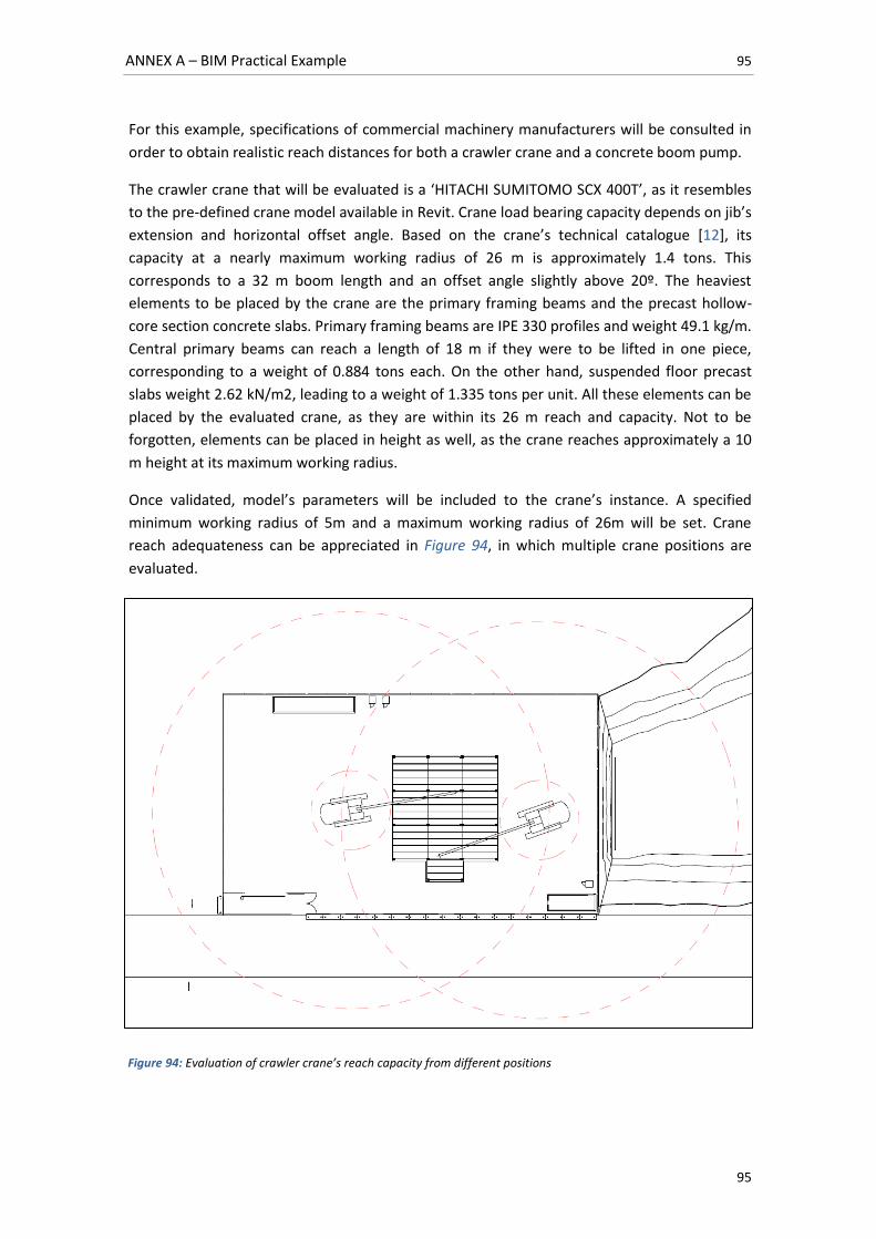
ANNEX A – BIM Practical Example 95
95
For this example, specifications of commercial machinery manufacturers will be consulted in
order to obtain realistic reach distances for both a crawler crane and a concrete boom pump.
The crawler crane that will be evaluated is a ‘HITACHI SUMITOMO SCX 400T’, as it resembles
to the pre-defined crane model available in Revit. Crane load bearing capacity depends on jib’s
extension and horizontal offset angle. Based on the crane’s technical catalogue [12], its
capacity at a nearly maximum working radius of 26 m is approximately 1.4 tons. This
corresponds to a 32 m boom length and an offset angle slightly above 20º. The heaviest
elements to be placed by the crane are the primary framing beams and the precast hollow-
core section concrete slabs. Primary framing beams are IPE 330 profiles and weight 49.1 kg/m.
Central primary beams can reach a length of 18 m if they were to be lifted in one piece,
corresponding to a weight of 0.884 tons each. On the other hand, suspended floor precast
slabs weight 2.62 kN/m2, leading to a weight of 1.335 tons per unit. All these elements can be
placed by the evaluated crane, as they are within its 26 m reach and capacity. Not to be
forgotten, elements can be placed in height as well, as the crane reaches approximately a 10
m height at its maximum working radius.
Once validated, model’s parameters will be included to the crane’s instance. A specified
minimum working radius of 5m and a maximum working radius of 26m will be set. Crane
reach adequateness can be appreciated in Figure 94, in which multiple crane positions are
evaluated.
Figure 94: Evaluation of crawler crane’s reach capacity from different positions
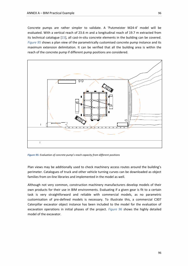
ANNEX A – BIM Practical Example 96
96
Concrete pumps are rather simpler to validate. A ‘Putzmeister M24-4’ model will be
evaluated. With a vertical reach of 23.6 m and a longitudinal reach of 19.7 m extracted from
its technical catalogue [15], all cast-in-situ concrete elements in the building can be covered.
Figure 95 shows a plan view of the parametrically customised concrete pump instance and its
maximum extension delimitation. It can be verified that all the building area is within the
reach of the concrete pump if different pump positions are considered.
Plan views may be additionally used to check machinery access routes around the building’s
perimeter. Catalogues of truck and other vehicle turning curves can be downloaded as object
families from on-line libraries and implemented in the model as well.
Although not very common, construction machinery manufacturers develop models of their
own products for their use in BIM environments. Evaluating if a given gear is fit to a certain
task is very straightforward and reliable with commercial models, as no parametric
customisation of pre-defined models is necessary. To illustrate this, a commercial C307
Caterpillar excavator object instance has been included to the model for the evaluation of
excavation operations in initial phases of the project. Figure 96 shows the highly detailed
model of the excavator.
Figure 95: Evaluation of concrete pump’s reach capacity from different positions
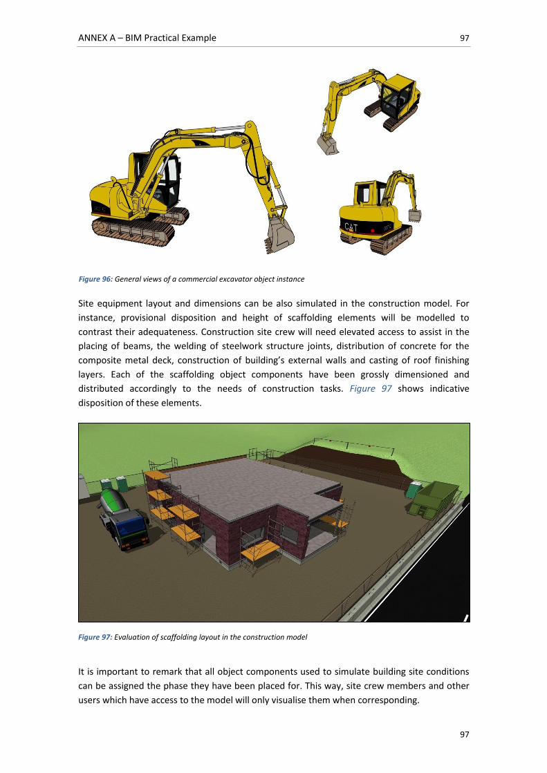
ANNEX A – BIM Practical Example 97
97
Site equipment layout and dimensions can be also simulated in the construction model. For
instance, provisional disposition and height of scaffolding elements will be modelled to
contrast their adequateness. Construction site crew will need elevated access to assist in the
placing of beams, the welding of steelwork structure joints, distribution of concrete for the
composite metal deck, construction of building’s external walls and casting of roof finishing
layers. Each of the scaffolding object components have been grossly dimensioned and
distributed accordingly to the needs of construction tasks. Figure 97 shows indicative
disposition of these elements.
Figure 97: Evaluation of scaffolding layout in the construction model
It is important to remark that all object components used to simulate building site conditions
can be assigned the phase they have been placed for. This way, site crew members and other
users which have access to the model will only visualise them when corresponding.
Figure 96: General views of a commercial excavator object instance
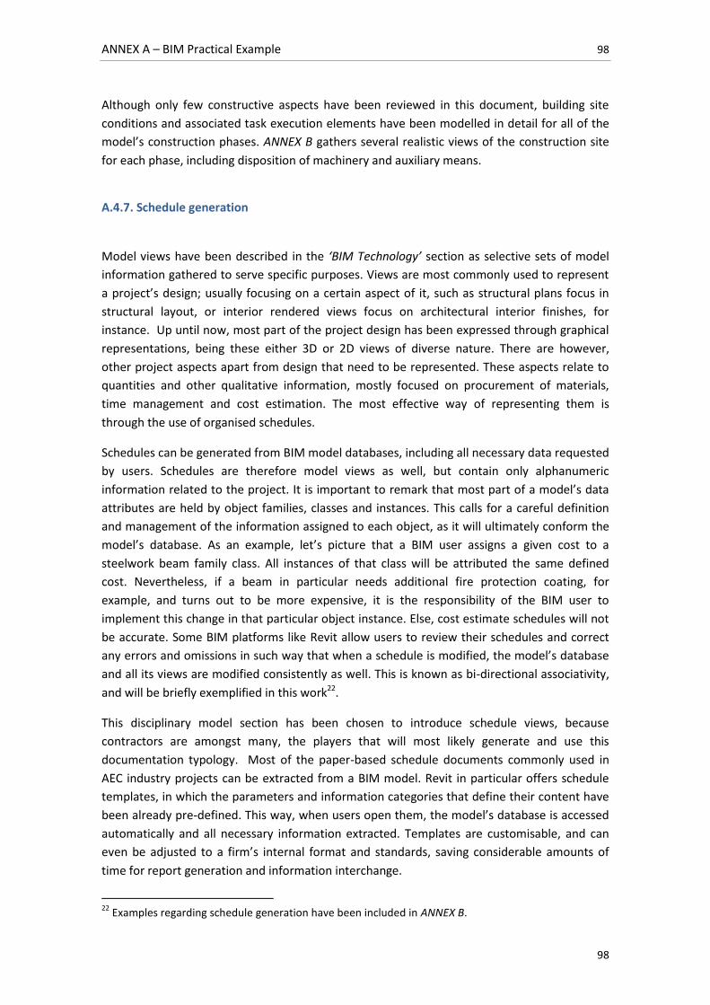
ANNEX A – BIM Practical Example 98
98
Although only few constructive aspects have been reviewed in this document, building site
conditions and associated task execution elements have been modelled in detail for all of the
model’s construction phases. ANNEX B gathers several realistic views of the construction site
for each phase, including disposition of machinery and auxiliary means.
A.4.7. Schedule generation
Model views have been described in the ‘BIM Technology’ section as selective sets of model
information gathered to serve specific purposes. Views are most commonly used to represent
a project’s design; usually focusing on a certain aspect of it, such as structural plans focus in
structural layout, or interior rendered views focus on architectural interior finishes, for
instance. Up until now, most part of the project design has been expressed through graphical
representations, being these either 3D or 2D views of diverse nature. There are however,
other project aspects apart from design that need to be represented. These aspects relate to
quantities and other qualitative information, mostly focused on procurement of materials,
time management and cost estimation. The most effective way of representing them is
through the use of organised schedules.
Schedules can be generated from BIM model databases, including all necessary data requested
by users. Schedules are therefore model views as well, but contain only alphanumeric
information related to the project. It is important to remark that most part of a model’s data
attributes are held by object families, classes and instances. This calls for a careful definition
and management of the information assigned to each object, as it will ultimately conform the
model’s database. As an example, let’s picture that a BIM user assigns a given cost to a
steelwork beam family class. All instances of that class will be attributed the same defined
cost. Nevertheless, if a beam in particular needs additional fire protection coating, for
example, and turns out to be more expensive, it is the responsibility of the BIM user to
implement this change in that particular object instance. Else, cost estimate schedules will not
be accurate. Some BIM platforms like Revit allow users to review their schedules and correct
any errors and omissions in such way that when a schedule is modified, the model’s database
and all its views are modified consistently as well. This is known as bi-directional associativity,
and will be briefly exemplified in this work22.
This disciplinary model section has been chosen to introduce schedule views, because
contractors are amongst many, the players that will most likely generate and use this
documentation typology. Most of the paper-based schedule documents commonly used in
AEC industry projects can be extracted from a BIM model. Revit in particular offers schedule
templates, in which the parameters and information categories that define their content have
been already pre-defined. This way, when users open them, the model’s database is accessed
automatically and all necessary information extracted. Templates are customisable, and can
even be adjusted to a firm’s internal format and standards, saving considerable amounts of
time for report generation and information interchange.
22
Examples regarding schedule generation have been included in ANNEX B.
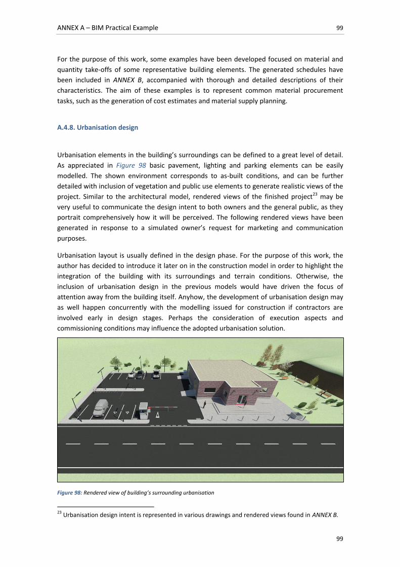
ANNEX A – BIM Practical Example 99
99
For the purpose of this work, some examples have been developed focused on material and
quantity take-offs of some representative building elements. The generated schedules have
been included in ANNEX B, accompanied with thorough and detailed descriptions of their
characteristics. The aim of these examples is to represent common material procurement
tasks, such as the generation of cost estimates and material supply planning.
A.4.8. Urbanisation design
Urbanisation elements in the building’s surroundings can be defined to a great level of detail.
As appreciated in Figure 98 basic pavement, lighting and parking elements can be easily
modelled. The shown environment corresponds to as-built conditions, and can be further
detailed with inclusion of vegetation and public use elements to generate realistic views of the
project. Similar to the architectural model, rendered views of the finished project23 may be
very useful to communicate the design intent to both owners and the general public, as they
portrait comprehensively how it will be perceived. The following rendered views have been
generated in response to a simulated owner’s request for marketing and communication
purposes.
Urbanisation layout is usually defined in the design phase. For the purpose of this work, the
author has decided to introduce it later on in the construction model in order to highlight the
integration of the building with its surroundings and terrain conditions. Otherwise, the
inclusion of urbanisation design in the previous models would have driven the focus of
attention away from the building itself. Anyhow, the development of urbanisation design may
as well happen concurrently with the modelling issued for construction if contractors are
involved early in design stages. Perhaps the consideration of execution aspects and
commissioning conditions may influence the adopted urbanisation solution.
Figure 98: Rendered view of building’s surrounding urbanisation
23
Urbanisation design intent is represented in various drawings and rendered views found in ANNEX B.
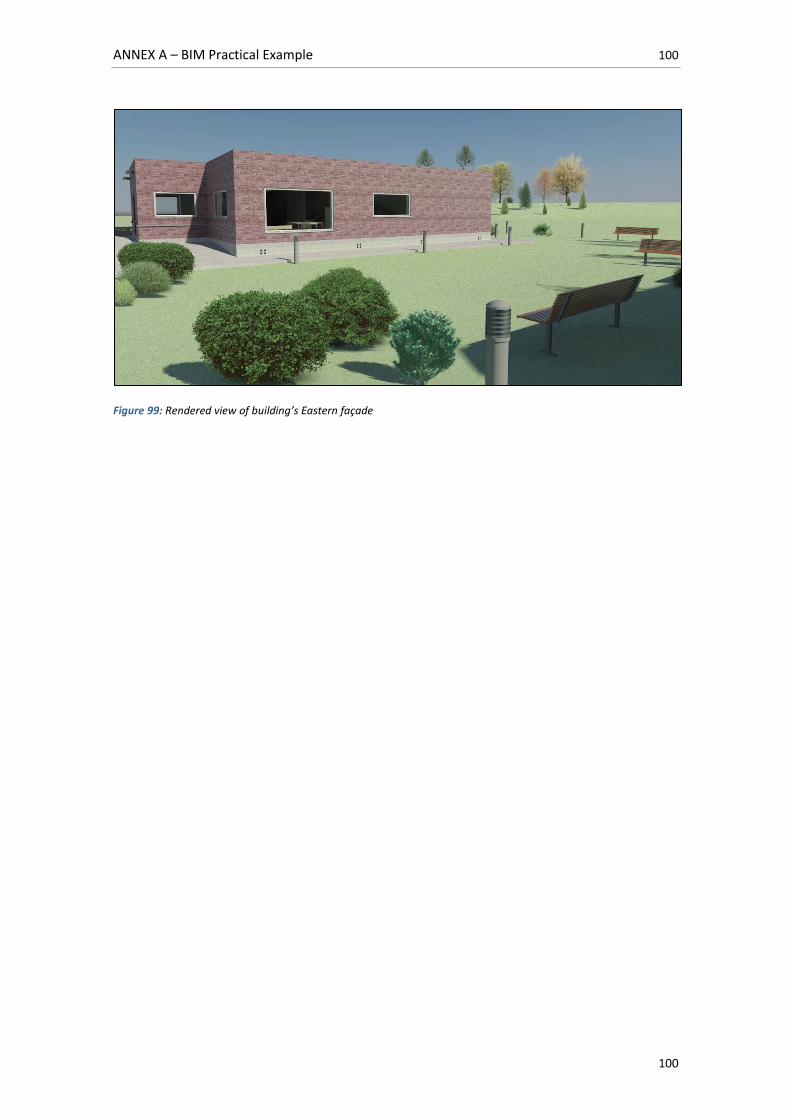
ANNEX A – BIM Practical Example 100
100
Figure 99: Rendered view of building’s Eastern façade
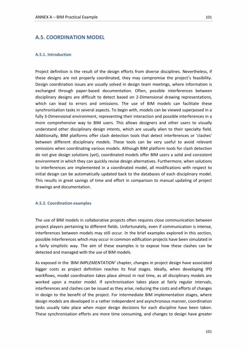
ANNEX A – BIM Practical Example 101
101
A.5. COORDINATION MODEL
A.5.1. Introduction
Project definition is the result of the design efforts from diverse disciplines. Nevertheless, if
these designs are not properly coordinated, they may compromise the project’s feasibility.
Design coordination issues are usually solved in design team meetings, where information is
exchanged through paper-based documentation. Often, possible interferences between
disciplinary designs are difficult to detect based on 2-Dimensional drawing representations,
which can lead to errors and omissions. The use of BIM models can facilitate these
synchronisation tasks in several aspects. To begin with, models can be viewed superposed in a
fully 3-Dimensional environment, representing their interaction and possible interferences in a
more comprehensive way to BIM users. This allows designers and other users to visually
understand other disciplinary design intents, which are usually alien to their specialty field.
Additionally, BIM platforms offer clash detection tools that detect interferences or ‘clashes’
between different disciplinary models. These tools can be very useful to avoid relevant
omissions when coordinating various models. Although BIM platform tools for clash detection
do not give design solutions (yet), coordinated models offer BIM users a solid and consistent
environment in which they can quickly revise design alternatives. Furthermore, when solutions
to interferences are implemented in a coordinated model, all modifications with respect to
initial design can be automatically updated back to the databases of each disciplinary model.
This results in great savings of time and effort in comparison to manual updating of project
drawings and documentation.
A.5.2. Coordination examples
The use of BIM models in collaborative projects often requires close communication between
project players pertaining to different fields. Unfortunately, even if communication is intense,
interferences between models may still occur. In the brief examples explored in this section,
possible interferences which may occur in common edification projects have been simulated in
a fairly simplistic way. The aim of these examples is to expose how these clashes can be
detected and managed with the use of BIM models.
As exposed in the ‘BIM IMPLEMENTATION’ chapter, changes in project design have associated
bigger costs as project definition reaches its final stages. Ideally, when developing IPD
workflows, model coordination takes place almost in real time, as all disciplinary models are
worked upon a master model. If synchronisation takes place at fairly regular intervals,
interferences and clashes can be issued as they arise, reducing the costs and efforts of changes
in design to the benefit of the project. For intermediate BIM implementation stages, where
design models are developed in a rather independent and asynchronous manner, coordination
tasks usually take place when major design decisions for each discipline have been taken.
These synchronisation efforts are more time consuming, and changes to design have greater
ANNEX A – BIM Practical Example 102
102
associated costs. The examples developed below correspond to a scenario where structural,
architectural and systems designs have been developed asynchronously. Therefore, the
models corresponding to each discipline have to be directly linked and coordinated.
Clash detection
The project treated in this work requires the implication of structural, architectural and
system designers, at the very least. Although systems (MEP) design has not been developed for
the building treated herein, some of its elements will be used to exemplify simple coordination
tasks.
It can be considered that restroom facilities require ventilation ducts that connect them to the
exterior, as they have been located in the building’s centre, away from any external wall. This
extraction system has been modelled in a very simplistic way. The duct segment starts off at
the restroom facilities, goes through the storage area and ends when the exterior is reached.
As shown in Figure 100, the ventilation duct has been intentionally placed at an approximate
ceiling height and may collide with the building’s structural framing system.
This presents a situation in which two disciplinary designs have to be put together and checked
for interferences. For this particular example, the duct line represents the systems design and
the building model itself pertains to both structural and architectural design. Although the
coordination check for this simple duct segment can be easily carried out in a manual way,
system designs are far more complex in reality. This is when clash detection tools prove to be
very useful.
Clash detection tools have a straightforward operational scheme. To begin with, BIM users
define object instance families and types from each model to be contrasted upon each other.
Once defined, the ‘interference check’ can be run. Two model object instances are considered
to clash or interfere with one another if their bounding volumes or areas intersect.
Figure 100: Ventilation duct connecting restroom with the exterior
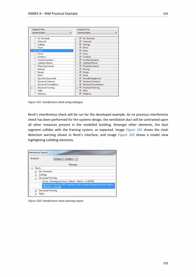
ANNEX A – BIM Practical Example 103
103
Figure 101: Interference check setup dialogue
Revit’s interference check will be run for the developed example. As no previous interference
check has been performed for the systems design, the ventilation duct will be contrasted upon
all other instances present in the modelled building. Amongst other elements, the duct
segment collides with the framing system, as expected. Image Figure 102 shows the clash
detection warning shown in Revit’s interface, and image Figure 103 shows a model view
highlighting colliding elements.
Figure 102: Interference check warning report
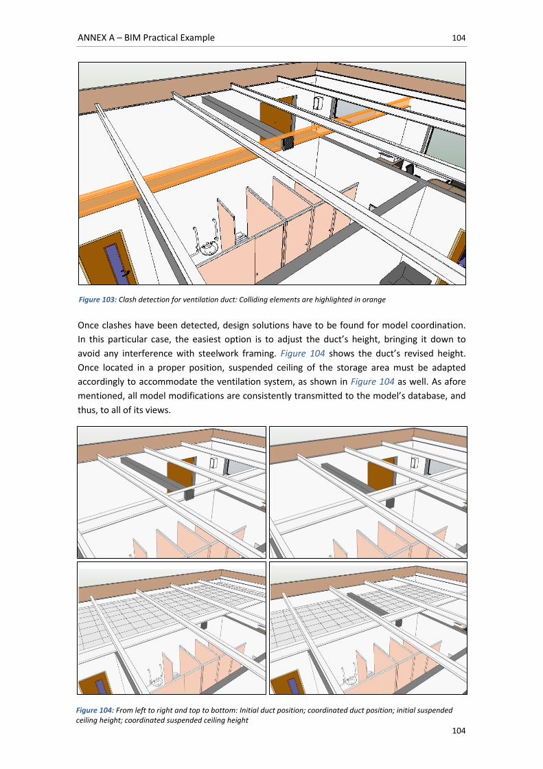
ANNEX A – BIM Practical Example 104
104
Once clashes have been detected, design solutions have to be found for model coordination.
In this particular case, the easiest option is to adjust the duct’s height, bringing it down to
avoid any interference with steelwork framing. Figure 104 shows the duct’s revised height.
Once located in a proper position, suspended ceiling of the storage area must be adapted
accordingly to accommodate the ventilation system, as shown in Figure 104 as well. As afore
mentioned, all model modifications are consistently transmitted to the model’s database, and
thus, to all of its views.
Figure 103: Clash detection for ventilation duct: Colliding elements are highlighted in orange
Figure 104: From left to right and top to bottom: Initial duct position; coordinated duct position; initial suspended ceiling height; coordinated suspended ceiling height
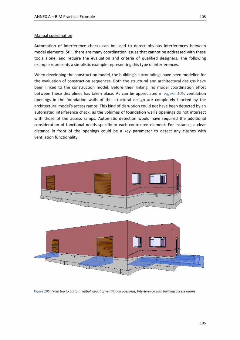
ANNEX A – BIM Practical Example 105
105
Manual coordination
Automation of interference checks can be used to detect obvious interferences between
model elements. Still, there are many coordination issues that cannot be addressed with these
tools alone, and require the evaluation and criteria of qualified designers. The following
example represents a simplistic example representing this type of interferences.
When developing the construction model, the building’s surroundings have been modelled for
the evaluation of construction sequences. Both the structural and architectural designs have
been linked to the construction model. Before their linking, no model coordination effort
between these disciplines has taken place. As can be appreciated in Figure 105, ventilation
openings in the foundation walls of the structural design are completely blocked by the
architectural model’s access ramps. This kind of disruption could not have been detected by an
automated interference check, as the volumes of foundation wall’s openings do not intersect
with those of the access ramps. Automatic detection would have required the additional
consideration of functional needs specific to each contrasted element. For instance, a clear
distance in front of the openings could be a key parameter to detect any clashes with
ventilation functionality.
Figure 105: From top to bottom: Initial layout of ventilation openings; Interference with building access ramps
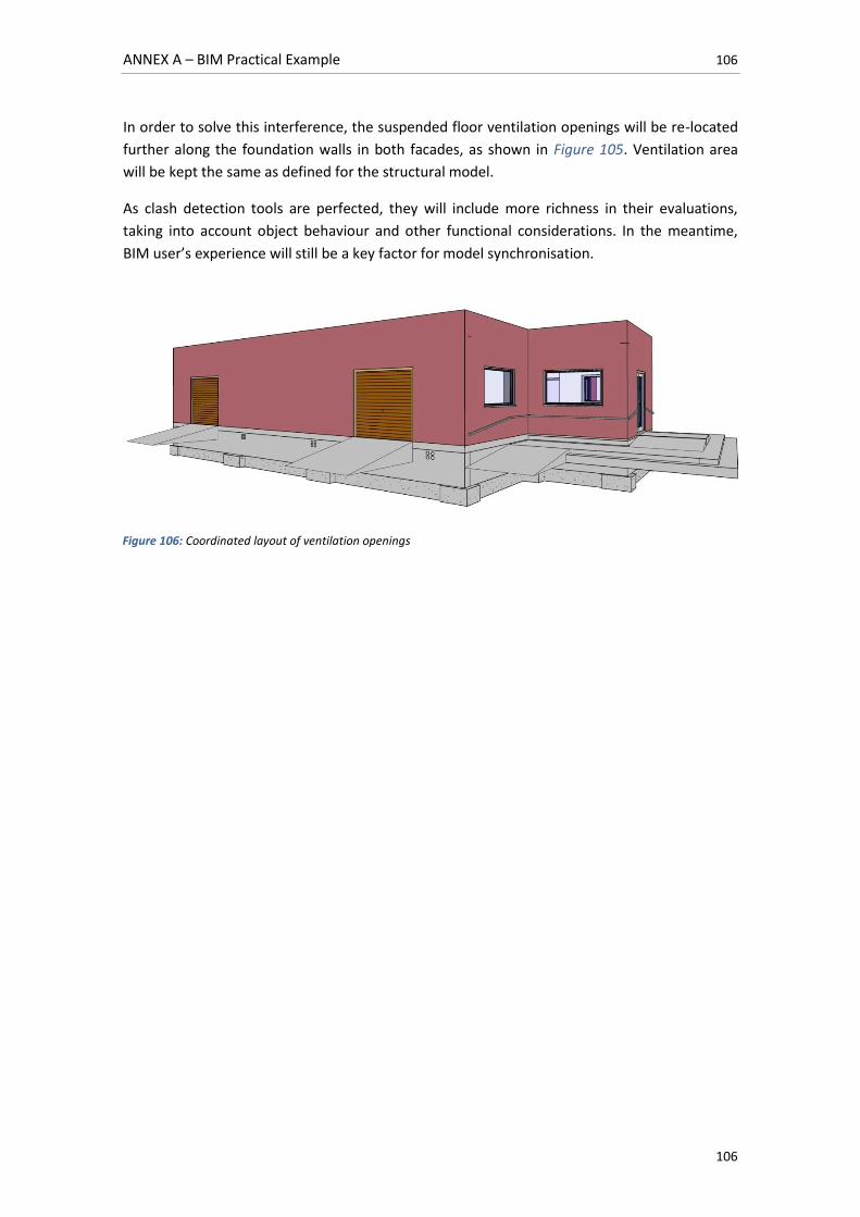
ANNEX A – BIM Practical Example 106
106
In order to solve this interference, the suspended floor ventilation openings will be re-located
further along the foundation walls in both facades, as shown in Figure 105. Ventilation area
will be kept the same as defined for the structural model.
As clash detection tools are perfected, they will include more richness in their evaluations,
taking into account object behaviour and other functional considerations. In the meantime,
BIM user’s experience will still be a key factor for model synchronisation.
Figure 106: Coordinated layout of ventilation openings
ANNEX A – BIM Practical Example 107
107
REFERENCES
[1]. ACIES. Forjados de Chapa Colaborante. [Online] s.l. : ACIES. Sesión Técnica Monográfica
nº4. [Consulted: 08 February 2014] Available at: <http://www.bimgenieria.com/wp-
content/uploads/2012/09/ChapaColaborante.pdf>.
[2]. Autodesk. Integrating Revit Structure and Robot Structural Analysis Professional. [Online]
s.l., U.S.A. : Autodesk, 2010. [Consulted: 2 February 2014] Available at:
<http://images.autodesk.com/adsk/files/linking_revit_structure_models_with_robot_structur
al_analysis.pdf>.
[3]. —. Autodesk Seek. [Online] s.l. : Autodesk. [Consulted: 06 February 2014] Available at:
<http://seek.autodesk.com/>.
[4]. Comisión Permanente de Estructuras de Acero. EAE: Instrucción de Acero Estructural. 1ª.
Madrid : Centro de Publicaciones Secretaría General Técnica Ministerio de Fomento, 2011.
ISBN 978-84-498-0904-0.
[5]. Comisión Permanente del Hormigón. EHE 08: Instrucción de Hormigón Estructural. 4ª.
Madrid : Centro de Publicaciones Secretaría General Técnica Ministerio de Fomento, 2010.
ISBN 978-84-498-0875-3.
[6]. CTE. CTE-DB-SE-AE: 2009; Documento Básico SE AE: Seguridad Estructural Acciones en la
Edificación. [Online] s.l., Spain : Ministerio de Fomento, Gobierno de España, 2009. [Consulted:
10 February 2014] Available at:
<http://www.codigotecnico.org/cte/export/sites/default/web/galerias/archivos/DB_SE-
AE_abril_2009.pdf>.
[7]. —. CTE-DB-HS: 2009; Documento Básico HS: Salubridad. [Online] s.l., Spain : Ministerio de
Fomento, Gobierno de España, 2009. [Consulted: 10 February 2014] Available at:
<http://www.codigotecnico.org/cte/export/sites/default/web/galerias/archivos/DB_HS_2009.
pdf>.
[8]. —. CTE-DB-SE: 2009; Documento Básico SE: Seguridad Estructural. [Online] s.l., Spain :
Ministerio de Fomento, Gobierno de España, 2009. [Consulted: 10 February 2014] Available at:
<http://www.codigotecnico.org/cte/export/sites/default/web/galerias/archivos/DB_SE_abril_
2009.pdf>.
[9]. —. CTE-DB-HE: 2006; Documento Básico HE: Ahorro de Energía. [Online] s.l., Spain :
Ministerio de Fomento, Gobierno de España, 2006. [Consulted: 10 February 2014] Available at:
<http://www.codigotecnico.org/cte/export/sites/default/web/galerias/archivos/DB_HE_abril_
2009.pdf>.
ANNEX A – BIM Practical Example 108
108
[10]. CYPE. Biblioteca de Detalles Constructivos: Detalles constructivos metálicos, de hormigón
y mixtos. [Online] s.l. : CYPE Ingenieros. [Consulted: 08 February 2014] Available at:
<http://detallesconstructivos.cype.es/Detalles_Constructivos_metalicos_de_hormigon_y_mixt
os.html>.
[11]. EUROPERFIL. Perfiles y Accesorios para Cerramientos Metálicos. [Online] s.l. :
EUROPERFIL. Catálogo General de Perfiles. [Consulted: 08 February 2014] Available at:
<http://www.guiasgtp.com/pdf/211005-b.pdf>,
<http://www.europerfil.es/web/productos.php?idf=9&accion=productos&idi=1&idm=200&idp
=129>.
[12]. HITACHI. SCX400T Hydraulic telescopic boom crawler crane. [Online] s.l., Japan : Hitachi
Sumitomo Heavy Industries Construction Crane Co. Ltd. [Consulted: 15 March 2013] Available
at: <http://www.delden-cse.com/cmsAdmin/uploads/scx400t-en-ratings_001.pdf>.
[13]. Instituto Eduardo Torroja de ciencias de la construcción; CEPCO; AICIA. Catálogo de
elementos constructivos del CTE. [Online] s.l., Spain : Ministerio de Vivienda, Gobierno de
España, January de 2010. Código Técnico de la Edificación. [Consulted: 10 February 2014]
Available at: <http://www.codigotecnico.org/web/galerias/archivos/CAT-EC-
v06.2_enero_10.pdf>.
[14]. PREVALESA; Galán Sanchez, Fernando. Ficha de las Características Técnicas -Según EHE
08- de las Losas/Forjados Alveolares Pretensadas Modelo PF15/20/26. [Online] s.l. :
PREVALESA S.L. [Consulted: 02 February 2014] Available at:
<http://www.prevalesa.es/doc/ei/ft_placa_alveolar.pdf>.
[15]. Putzmeister. Autobombas de hormigón. [Online] s.l., Germany : Putzmeister AG, 2007.
[Consulted: 15 March 2013] Available at:
<http://www.putzmeister.es/pm_spain/data/genericodeautobombas.pdf>.