
ANNEX 8 RESOLUTION MSC.158(78) (adopted on 20 May …… · ADOPTION OF AMENDMENTS TO THE TECHNICAL...
48
MSC 78/26/Add.1 I:\MSC\78\26-Add.1.doc ANNEX 8 RESOLUTION MSC.158(78) (adopted on 20 May 2004) ADOPTION OF AMENDMENTS TO THE TECHNICAL PROVISIONS FOR MEANS OF ACCESS FOR INSPECTIONS THE MARITIME SAFETY COMMITTEE, RECALLING Article 28(b) of the Convention on the International Maritime Organization concerning the functions of the Committee, NOTING the Technical provisions for means of access for inspections (hereinafter referred to as the Technical provisions), adopted by resolution MSC.133(76), which are mandatory under SOLAS regulation II-1/3-6 on Access to and within spaces in the cargo area of oil tankers and bulk carriers adopted by resolution MSC.134(76), ACKNOWLEDGING concerns expressed with regard to perceived problems which might be encountered when implementing the requirements of the Technical provisions, NOTING ALSO the amendments to the aforementioned SOLAS regulation II-1/3-6 adopted by resolution MSC.151(78) to address the above concerns, HAVING CONSIDERED, at its seventy-eighth session, amendments to the Technical provisions, prepared and circulated in accordance with article VIII and regulation II-1/3-6 of the 1974 SOLAS Convention, 1. ADOPTS amendments to the Technical provisions for means of access for inspections, the text of which is set out in the Annex to the present resolution; 2. DETERMINES, in accordance with article VIII(b)(vi)(2)(bb) of the Convention, that the said amendments shall be deemed to have been accepted on 1 July 2005, unless, prior to that date, more than one third of the Contracting Governments to the Convention or Contracting Governments the combined merchant fleets of which constitute not less than 50% of the gross tonnage of the worlds merchant fleet, have notified their objections to the amendments; 3. INVITES SOLAS Contracting Governments to note that, in accordance with article VIII(b)(vii)(2) of the Convention, the amendments shall enter into force on 1 January 2006 upon their acceptance in accordance with paragraph 2 above; 4. REQUESTS the Secretary-General to transmit certified copies of this resolution and the text of the Technical provisions contained in the Annex to all Contracting Governments to the Convention; 5. FURTHER REQUESTS the Secretary-General to transmit copies of this resolution and the Annex to all Members of the Organization, which are not Contracting Governments to the Convention.
-
Upload
truongduong -
Category
Documents
-
view
217 -
download
0
Transcript of ANNEX 8 RESOLUTION MSC.158(78) (adopted on 20 May …… · ADOPTION OF AMENDMENTS TO THE TECHNICAL...

MSC 78/26/Add.1
I:\MSC\78\26-Add.1.doc
ANNEX 8
RESOLUTION MSC.158(78) (adopted on 20 May 2004)
ADOPTION OF AMENDMENTS TO THE TECHNICAL PROVISIONS FOR MEANS
OF ACCESS FOR INSPECTIONS THE MARITIME SAFETY COMMITTEE, RECALLING Article 28(b) of the Convention on the International Maritime Organization concerning the functions of the Committee, NOTING the Technical provisions for means of access for inspections (hereinafter referred to as �the Technical provisions�), adopted by resolution MSC.133(76), which are mandatory under SOLAS regulation II-1/3-6 on Access to and within spaces in the cargo area of oil tankers and bulk carriers adopted by resolution MSC.134(76), ACKNOWLEDGING concerns expressed with regard to perceived problems which might be encountered when implementing the requirements of the Technical provisions, NOTING ALSO the amendments to the aforementioned SOLAS regulation II-1/3-6 adopted by resolution MSC.151(78) to address the above concerns,
HAVING CONSIDERED, at its seventy-eighth session, amendments to the Technical provisions, prepared and circulated in accordance with article VIII and regulation II-1/3-6 of the 1974 SOLAS Convention, 1. ADOPTS amendments to the Technical provisions for means of access for inspections, the text of which is set out in the Annex to the present resolution; 2. DETERMINES, in accordance with article VIII(b)(vi)(2)(bb) of the Convention, that the said amendments shall be deemed to have been accepted on 1 July 2005, unless, prior to that date, more than one third of the Contracting Governments to the Convention or Contracting Governments the combined merchant fleets of which constitute not less than 50% of the gross tonnage of the world�s merchant fleet, have notified their objections to the amendments; 3. INVITES SOLAS Contracting Governments to note that, in accordance with article VIII(b)(vii)(2) of the Convention, the amendments shall enter into force on 1 January 2006 upon their acceptance in accordance with paragraph 2 above; 4. REQUESTS the Secretary-General to transmit certified copies of this resolution and the text of the Technical provisions contained in the Annex to all Contracting Governments to the Convention; 5. FURTHER REQUESTS the Secretary-General to transmit copies of this resolution and the Annex to all Members of the Organization, which are not Contracting Governments to the Convention.

MSC 78/26/Add.1
I:\MSC\78\26-Add.1.doc
ANNEX 9
DRAFT AMENDMENTS TO CHAPTER XII OF THE INTERNATIONAL CONVENTION FOR THE SAFETY OF LIFE AT SEA, 1974, AS AMENDED
CHAPTER XII
ADDITIONAL SAFETY MEASURES FOR BULK CARRIERS
1 The existing text of chapter XII is replaced by the following:
�Regulation 1
Definitions
For the purpose of this chapter: 1 Bulk carrier means a ship which is intended primarily to carry dry cargo in bulk, including such types as ore carriers and combination carriers.∗ 2 Bulk carrier of single-side skin construction means a bulk carrier which is constructed generally with single deck, top-side tanks and hopper side tanks in cargo spaces, in which: .1 any part of a cargo hold is bounded by the side shell; or .2 where one or more cargo holds are bounded by a double-side skin, the
width of which is less than 760 mm in bulk carriers constructed before 1 January 2000 and less than 1,000 mm in bulk carriers constructed on or after 1 January 2000 but before [date of entry into force of the amendments], the distance being measured perpendicular to the side shell.
Such ships include combination carriers in which any part of a cargo hold is bounded by the side shell.
∗ Reference is made to:
.1 For ships constructed before [date of entry into force of the amendments], resolution 6, Interpretation of the definition of �bulk carrier�, as given in chapter IX of SOLAS 1974, as amended in 1994, adopted by the 1997 SOLAS Conference.
.2 The Interpretation of the provisions of SOLAS chapter XII on Additional safety measures for bulk carriers, adopted by the Maritime Safety Committee of the Organization by resolution MSC.79(70).
.3 The application provisions of Annex 1 to the Interpretation of the provisions of SOLAS chapter XII on Additional safety measures for bulk carriers, adopted by the Maritime Safety Committee of the Organization by resolution MSC.89(71).
.4 The Guidance for the identification of a ship as a bulk carrier to be developed by the Organization.
MSC 78/26/Add.1 ANNEX 9 Page 2
I:\MSC\78\26-Add.1.doc
3 Bulk carrier of double-side skin construction means a bulk carrier as defined in paragraph 1, in which all cargo holds are bounded by a double-side skin, other than as defined in paragraph 2.2. 4 Double-side skin means a configuration where each ship side is constructed by the side shell and a longitudinal bulkhead connecting the double bottom and the deck. Hopper side tanks and top-side tanks may, where fitted, be integral parts of the double-side skin configuration. 5 Length of a bulk carrier means the length as defined in the International Convention on Load Lines in force. 6 Solid bulk cargo means any material, other than liquid or gas, consisting of a combination of particles, granules or any larger pieces of material, generally uniform in composition, which is loaded directly into the cargo spaces of a ship without any intermediate form of containment. 7 Bulk carrier bulkhead and double bottom strength standards means �Standards for the evaluation of scantlings of the transverse water-tight vertically corrugated bulkhead between the two foremost cargo holds and for the evaluation of allowable hold loading of the foremost cargo hold� adopted by resolution 4 of the Conference of Contracting Governments to the International Convention for the Safety of Life at Sea, 1974 on 27 November 1997, as may be amended by the Organization, provided that such amendments are adopted, brought into force and take effect in accordance with the provisions of article VIII of the present Convention concerning the amendment procedures applicable to the Annex other than chapter I. 8 Bulk carriers constructed means bulk carriers the keels of which are laid or which are at a similar stage of construction. 9 A similar stage of construction means the stage at which:
.1 construction identifiable with a specific ship begins; and
.2 assembly of that ship has commenced comprising at least 50 tonnes or one per cent of the estimated mass of all structural material, whichever is less.
10 Breadth (B) of a bulk carrier means the breadth as defined in the International Convention on Load Lines in force.
Regulation 2
Application
Bulk carriers shall comply with the requirements of this chapter in addition to the applicable requirements of other chapters.

MSC 78/26/Add.1 ANNEX 9
Page 3
I:\MSC\78\26-Add.1.doc
Regulation 3
Implementation schedule Bulk carriers constructed before 1 July 1999 to which regulations 4 or 6 apply shall comply with the provisions of such regulations according to the following schedule, with reference to the enhanced programme of inspections required by regulation XI-1/2: .1 bulk carriers, which are 20 years of age and over on 1 July 1999, by the
date of the first intermediate survey or the first periodical survey after 1 July 1999, whichever comes first;
.2 bulk carriers, which are 15 years of age and over but less than 20 years of
age on 1 July 1999, by the date of the first periodical survey after 1 July 1999, but not later than 1 July 2002; and
.3 bulk carriers, which are less than 15 years of age on 1 July 1999, by the
date of the first periodical survey after the date on which the ship reaches 15 years of age, but not later than the date on which the ship reaches 17 years of age.
Regulation 4
Damage stability requirements applicable to bulk carriers 1 Bulk carriers of 150 m in length and upwards of single-side skin construction, designed to carry solid bulk cargoes having a density of 1,000 kg/m3 and above, constructed on or after 1 July 1999 shall, when loaded to the summer load line, be able to withstand flooding of any one cargo hold in all loading conditions and remain afloat in a satisfactory condition of equilibrium, as specified in paragraph 4. 2 Bulk carriers of 150 m in length and upwards of double-side skin construction with a double-side skin space less than B/5 wide, designed to carry solid bulk cargoes having a density of 1,000 kg/m3 and above, constructed on or after [date of entry into force of the amendments] shall, when loaded to the summer load line, be able to withstand flooding of any one cargo hold in all loading conditions and remain afloat in a satisfactory condition of equilibrium, as specified in paragraph 4. 3 Bulk carriers of 150 m in length and upwards of single-side skin construction, carrying solid bulk cargoes having a density of 1,780 kg/m3 and above, constructed before 1 July 1999 shall, when loaded to the summer load line, be able to withstand flooding of the foremost cargo hold in all loading conditions and remain afloat in a satisfactory condition of equilibrium, as specified in paragraph 4. This requirement shall be complied with in accordance with the implementation schedule specified in regulation 3.

MSC 78/26/Add.1 ANNEX 9 Page 4
I:\MSC\78\26-Add.1.doc
4 Subject to the provisions of paragraph 7, the condition of equilibrium after flooding shall satisfy the condition of equilibrium laid down in the Annex to resolution A.320(IX) - Regulation equivalent to regulation 27 of the International Convention on Load Lines, 1966, as amended by resolution A.514(13). The assumed flooding need only take into account flooding of the cargo hold space to the water level outside the ship in that flooded condition. The permeability of a loaded hold shall be assumed as 0.9 and the permeability of an empty hold shall be assumed as 0.95, unless a permeability relevant to a particular cargo is assumed for the volume of a flooded hold occupied by cargo and a permeability of 0.95 is assumed for the remaining empty volume of the hold. 5 Bulk carriers constructed before 1 July 1999, which have been assigned a reduced freeboard in compliance with regulation 27(7) of the International Convention on Load Lines, 1966, as adopted on 5 April 1966, may be considered as complying with paragraph 3 of this regulation. 6 Bulk carriers which have been assigned a reduced freeboard in compliance with the provisions of paragraph (8) of the regulation equivalent to regulation 27 of the International Convention on Load Lines, 1966, adopted by resolution A.320(IX), as amended by resolution A.514(13), may be considered as complying with paragraphs 1 or 3, as appropriate. 7 On bulk carriers which have been assigned reduced freeboard in compliance with the provisions of regulation 27(8) of Annex B of the Protocol of 1988 relating to the International Convention on Load Lines, 1966, the condition of equilibrium after flooding shall satisfy the relevant provisions of that Protocol.
Regulation 5
Structural strength of bulk carriers
1 Bulk carriers of 150 m in length and upwards of single-side skin construction, designed to carry solid bulk cargoes having a density of 1,000 kg/m3 and above constructed on or after 1 July 1999, shall have sufficient strength to withstand flooding of any one cargo hold to the water level outside the ship in that flooded condition in all loading and ballast conditions, taking also into account dynamic effects resulting from the presence of water in the hold, and taking into account the recommendations adopted by the Organization.∗
2 Bulk carriers of 150 m in length and upwards of double-side skin construction, with a double-side skin space less than B/5 wide, designed to carry bulk cargoes having a density of 1,000 kg/m3 and above constructed on or after [date of entry into force of the amendments], shall comply with the structural strength provisions of paragraph 1.
∗ Refer to resolution 3, Recommendation on compliance with SOLAS regulation XII/5, adopted by
the 1997 SOLAS Conference.

MSC 78/26/Add.1 ANNEX 9
Page 5
I:\MSC\78\26-Add.1.doc
Regulation 6 Structural and other requirements for bulk carriers
1 Bulk carriers of 150 m in length and upwards of single-side skin construction, carrying solid bulk cargoes having a density of 1,780 kg/m3 and above, constructed before 1 July 1999, shall comply with the following requirements in accordance with the implementation schedule specified in regulation 3:
.1 The transverse watertight bulkhead between the two foremost cargo holds and the double bottom of the foremost cargo hold shall have sufficient strength to withstand flooding of the foremost cargo hold, taking also into account dynamic effects resulting from the presence of water in the hold, in compliance with the Bulk carrier bulkhead and double bottom strength standards. For the purpose of this regulation, the Bulk carrier bulkhead and double bottom strength standards shall be treated as mandatory.
.2 In considering the need for, and the extent of, strengthening of the
transverse watertight bulkhead or double bottom to meet the requirements of paragraph 1.1, the following restrictions may be taken into account:
.1 restrictions on the distribution of the total cargo weight between the
cargo holds; and
.2 restrictions on the maximum deadweight.
.3 For bulk carriers using either of, or both, the restrictions given in paragraphs 1.2.1 and 1.2.2 above for the purpose of fulfilling the requirements of paragraph 1.1, these restrictions shall be complied with whenever solid bulk cargoes having a density of 1,780 kg/m3 and above are carried.
2 Bulk carriers of 150 m in length and upwards of double-side skin construction, constructed on or after [date of entry into force of the amendments] shall comply with the following requirements:
.1 Primary stiffening structures of the double-side skin shall not be placed inside the cargo hold space.
.2 Subject to the provisions below, the distance between the outer shell and
the inner shell at any transverse section shall not be less than 1,000 mm measured perpendicular to the side shell. The double-side skin construction shall be such as to allow access for inspection as provided in regulation II-1/3-6 and the Technical provisions referring thereto.
.1 The clearances below need not be maintained in way of cross ties,
upper and lower end brackets of transverse framing or end brackets of longitudinal framing.
MSC 78/26/Add.1 ANNEX 9 Page 6
I:\MSC\78\26-Add.1.doc
.2 The minimum width of the clear passage through the double-side skin space in way of obstructions such as piping or vertical ladders shall not be less than 600 mm.
.3 Where the inner and/or outer skins are transversely framed, the
minimum clearance between the inner surfaces of the frames shall not be less than 600 mm.
.4 Where the inner and outer skins are longitudinally framed, the
minimum clearance between the inner surfaces of the frames shall not be less than 800 mm. Outside the parallel part of the cargo hold length, this clearance may be reduced where necessitated by the structural configuration but in no case shall be less than 600 mm.
.5 The minimum clearance referred to above shall be the shortest
distance measured between assumed lines connecting the inner surfaces of the frames on the inner and outer skins.
3 The double-side skin spaces shall be coated in accordance with the requirements of regulation II-1/3-2 and the [Performance standards for coatings]∗ adopted by the Organization by resolution MSC.[..]([..]), as may be amended by the Organization, provided that such amendments are adopted, brought into force and take effect in accordance with the provisions of article VIII of the present Convention concerning the amendment procedures applicable to the Annex other than chapter I. 4 The double-side skin spaces, with the exception of top-side wing tanks, if fitted, shall not be used for the carriage of cargo.
Regulation 7
Survey and maintenance of bulk carriers 1 Bulk carriers of 150 m in length and upwards of single-side skin construction, constructed before 1 July 1999, of 10 years of age and over, shall not carry solid bulk cargoes having a density of 1,780 kg/m3 and above unless they have satisfactorily undergone either:
.1 a periodical survey, in accordance with the enhanced programme of
inspections during surveys required by regulation XI-1/2, or .2 a survey of all cargo holds to the same extent as required for periodical
surveys in the enhanced programme of inspections during surveys required by regulation XI-1/2.
∗ Performance standards for coatings, to be developed by the Organization.

MSC 78/26/Add.1 ANNEX 9
Page 7
I:\MSC\78\26-Add.1.doc
2 Bulk carriers shall comply with the maintenance requirements provided in regulation II-1/3-1 and the Standards for owners� inspections and maintenance of bulk carrier hatch covers adopted by the Organization by resolution MSC.[..]([..]), as may be amended by the Organization, provided that such amendments are adopted, brought into force and take effect in accordance with the provisions of article VIII of the present Convention concerning the amendment procedures applicable to the Annex other than chapter I.
Regulation 8
Information on compliance with requirements for bulk carriers 1 The booklet required by regulation VI/7.2 shall be endorsed by the Administration or on its behalf, to indicate that regulations 4, 5, 6 and 7, as appropriate, are complied with. 2 Any restrictions imposed on the carriage of solid bulk cargoes having a density of 1,780 kg/m3 and above in accordance with the requirements of regulations 6 and 14 shall be identified and recorded in the booklet referred to in paragraph 1. 3 A bulk carrier to which paragraph 2 applies shall be permanently marked on the side shell at midships, port and starboard, with a solid equilateral triangle having sides of 500 mm and its apex 300 mm below the deck line, and painted a contrasting colour to that of the hull.
Regulation 9 Requirements for bulk carriers not being capable of complying with regulation 4.3
due to the design configuration of their cargo holds For bulk carriers constructed before 1 July 1999 being within the application limits of regulation 4.3, which have been constructed with an insufficient number of transverse watertight bulkheads to satisfy that regulation, the Administration may allow relaxation from the application of regulations 4.3 and 6 on condition that they shall comply with the following requirements: .1 for the foremost cargo hold, the inspections prescribed for the annual
survey in the enhanced programme of inspections during surveys required by regulation XI-1/2 shall be replaced by the inspections prescribed therein for the intermediate survey of cargo holds;
.2 are provided with bilge well high water level alarms in all cargo holds, or
in cargo conveyor tunnels, as appropriate, giving an audible and visual alarm on the navigation bridge, as approved by the Administration or an organization recognized by it in accordance with the provisions of regulation XI-1/1; and
MSC 78/26/Add.1 ANNEX 9 Page 8
I:\MSC\78\26-Add.1.doc
.3 are provided with detailed information on specific cargo hold flooding scenarios. This information shall be accompanied by detailed instructions on evacuation preparedness under the provisions of section 8 of the International Safety Management (ISM) Code and be used as the basis for crew training and drills.
Regulation 10
Solid bulk cargo density declaration 1 Prior to loading bulk cargo on bulk carriers of 150 m in length and upwards, the shipper shall declare the density of the cargo, in addition to providing the cargo information required by regulation VI/2. 2 For bulk carriers to which regulation 6 applies, unless such bulk carriers comply with all relevant requirements of this chapter applicable to the carriage of solid bulk cargoes having a density of 1,780 kg/m3 and above, any cargo declared to have a density within the range 1,250 kg/m3 to 1,780 kg/m3 shall have its density verified by an accredited testing organization.∗
Regulation 11
Loading instrument (Unless provided otherwise, this regulation applies to bulk carriers regardless of their date of construction) 1 Bulk carriers of 150 m in length and upwards shall be fitted with a loading instrument capable of providing information on hull girder shear forces and bending moments, taking into account the recommendation adopted by the Organization.∗∗
2 Bulk carriers of 150 m in length and upwards constructed before 1 July 1999 shall comply with the requirements of paragraph 1 not later than the date of the first intermediate or periodical survey of the ship to be carried out after 1 July 1999. 3 Bulk carriers of less than 150 m in length constructed on or after [date of entry into force of the amendments] shall be fitted with a loading instrument capable of providing information on the ship�s stability in the intact condition. The computer software shall be approved for stability calculations by the Administration and shall be provided with standard conditions for testing purposes relating to the approved stability information.∗∗∗
∗ In verifying the density of solid bulk cargoes, reference should be made to the Uniform method of
measurement of the density of bulk cargoes (MSC/Circ.908). ∗∗ Refer to the Recommendation on loading instruments, adopted by resolution 5 of the
1997 SOLAS Conference. ∗∗∗ Refer to the relevant parts of the appendix to the Guidelines for the on-board use and application of
computers (MSC/Circ.891).

MSC 78/26/Add.1 ANNEX 9
Page 9
I:\MSC\78\26-Add.1.doc
Regulation 12
Hold, ballast and dry space water ingress alarms
(This regulation applies to bulk carriers regardless of their date of construction) 1 Bulk carriers shall be fitted with water level detectors:
.1 in each cargo hold, giving audible and visual alarms, one when the water level above the inner bottom in any hold reaches a height of 0.5 m and another at a height not less than 15% of the depth of the cargo hold but not more than 2 m. On bulk carriers to which regulation 9.2 applies, detectors with only the latter alarm need be installed. The water level detectors shall be fitted in the aft end of the cargo holds. For cargo holds which are used for water ballast, an alarm overriding device may be installed. The visual alarms shall clearly discriminate between the two different water levels detected in each hold;
.2 in any ballast tank forward of the collision bulkhead required by
regulation II-1/11, giving an audible and visual alarm when the liquid in the tank reaches a level not exceeding 10% of the tank capacity. An alarm overriding device may be installed to be activated when the tank is in use; and
.3 in any dry or void space other than a chain cable locker, any part of which
extends forward of the foremost cargo hold, giving an audible and visual alarm at a water level of 0.1 m above the deck. Such alarms need not be provided in enclosed spaces the volume of which does not exceed 0.1% of the ship�s maximum displacement volume.
2 The audible and visual alarms specified in paragraph 1 shall be located on the navigation bridge. 3 Bulk carriers constructed before 1 July 2004 shall comply with the requirements of this regulation not later than the date of the annual, intermediate or renewal survey of the ship to be carried out after 1 July 2004, whichever comes first.
Regulation 13
Availability of pumping systems∗
(This regulation applies to bulk carriers regardless of their date of construction) 1 On bulk carriers, the means for draining and pumping ballast tanks forward of the collision bulkhead and bilges of dry spaces any part of which extends forward of the foremost cargo hold shall be capable of being brought into operation from a readily
∗ Refer to Interpretation of SOLAS regulation XII/13 (MSC/Circ.1069).

MSC 78/26/Add.1 ANNEX 9 Page 10
I:\MSC\78\26-Add.1.doc
accessible enclosed space, the location of which is accessible from the navigation bridge or propulsion machinery control position without traversing exposed freeboard or superstructure decks. Where pipes serving such tanks or bilges pierce the collision bulkhead, valve operation by means of remotely operated actuators may be accepted, as an alternative to the valve control specified in regulation II-1/11.4, provided that the location of such valve controls complies with this regulation. 2 Bulk carriers constructed before 1 July 2004 shall comply with the requirements of this regulation not later than the date of the first intermediate or renewal survey of the ship to be carried out after 1 July 2004, but in no case later than 1 July 2007.
Regulation 14
Restrictions from sailing with any hold empty
Bulk carriers of 150 m in length and upwards of single-side skin construction, carrying cargoes having a density of 1,780 kg/m3 and above, if not meeting the requirements of regulation 5.1 and the Standards and criteria for side structures of bulk carriers of single-side skin construction, adopted by the Organization by resolution MSC.[..]([..]), as may be amended by the Organization, provided that such amendments are adopted, brought into force and take effect in accordance with the provisions of article VIII of the present Convention concerning the amendment procedures applicable to the Annex other than chapter I, shall not sail with any hold loaded to less than 10% of the hold�s maximum allowable cargo weight when in the full load condition, after reaching 10 years of age. The applicable full load condition for this regulation is a load equal to or greater than 90% of the ship�s deadweight at the relevant assigned freeboard.�
***

MSC 78/26/Add.1 ANNEX 8 Page 2
I:\MSC\78\26-Add.1.doc
ANNEX
AMENDMENTS TO THE TECHNICAL PROVISIONS FOR
MEANS OF ACCESS FOR INSPECTIONS (RESOLUTION MSC.133(76))
1 The existing text of the Technical provisions for means of access for inspections is replaced with the following:
"1 Preamble 1.1 It has long been recognized that the only way of ensuring that the condition of a ship�s structure is maintained to conform with the applicable requirements is for all its components to be surveyed on a regular basis throughout their operational life. This will ensure that they are free from damage such as cracks, buckling or deformation due to corrosion, overloading, or contact damage and that thickness diminution is within established limits. The provision of suitable means of access to the hull structure for the purpose of carrying out overall and close-up surveys and inspections is essential and such means should be considered and provided for at the ship design stage. 1.2 Ships should be designed and built with due consideration as to how they will be surveyed by flag State inspectors and classification society surveyors during their in-service life and how the crew will be able to monitor the condition of the ship. Without adequate access, the structural condition of the ship can deteriorate undetected and major structural failure can arise. A comprehensive approach to design and maintenance is required to cover the whole projected life of the ship. 1.3 In order to address this issue, the Organization has developed these Technical provisions for means of access for inspections (hereinafter called the �Technical provisions�), intended to facilitate close-up inspections and thickness measurements of the ship�s structure referred to in SOLAS regulation II-1/3-6 on Access to and within spaces in, and forward of, the cargo area of oil tankers and bulk carriers. The Technical provisions do not apply to the cargo tanks of combined chemical/oil tankers complying with the provisions of the IBC Code. 1.4 Permanent means of access which are designed to be integral parts of the structure itself are preferred and Administrations may allow reasonable deviations to facilitate such designs. 2 Definitions For the purpose of these Technical provisions, the following definitions apply in addition to those provided in the 1974 SOLAS Convention, as amended, and in resolution A.744(18), as amended:

MSC 78/26/Add.1 ANNEX 8
Page 3
I:\MSC\78\26-Add.1.doc
.1 Rung means the step of a vertical ladder or step on the vertical surface. .2 Tread means the step of an inclined ladder or step for the vertical access
opening. .3 Flight of an inclined ladder means the actual stringer length of an inclined
ladder. For vertical ladders, it is the distance between the platforms. .4 Stringer means:
.1 the frame of a ladder; or
.2 the stiffened horizontal plating structure fitted on the side shell, transverse bulkheads and/or longitudinal bulkheads in the space. For the purpose of ballast tanks of less than 5 m width forming double side spaces, the horizontal plating structure is credited as a stringer and a longitudinal permanent means of access, if it provides a continuous passage of 600 mm or more in width past frames or stiffeners on the side shell or longitudinal bulkhead. Openings in stringer plating utilized as permanent means of access shall be arranged with guard rails or grid covers to provide safe passage on the stringer or safe access to each transverse web.
.5 Vertical ladder means a ladder of which the inclined angle is 70º and over
up to 90º. A vertical ladder shall not be skewed by more than 2º.
.6 Overhead obstructions mean the deck or stringer structure including stiffeners above the means of access.
.7 Distance below deck head means the distance below the plating.
.8 Cross deck means the transverse area of the main deck which is located
inboard and between hatch coamings. 3 Technical provisions 3.1 Structural members subject to the close-up inspections and thickness measurements of the ship�s structure referred to in SOLAS regulation II-1/3-6, except those in double bottom spaces, shall be provided with a permanent means of access to the extent as specified in table 1 and table 2, as applicable. For oil tankers and wing ballast tanks of ore carriers, approved alternative methods may be used in combination with the fitted permanent means of access, provided that the structure allows for its safe and effective use. 3.2 Permanent means of access should as far as possible be integral to the structure of the ships, thus ensuring that they are robust and at the same time contributing to the overall strength of the structure of the ship. 3.3 Elevated passageways forming sections of a permanent means of access, where fitted, shall have a minimum clear width of 600 mm, except for going around vertical

MSC 78/26/Add.1 ANNEX 8 Page 4
I:\MSC\78\26-Add.1.doc
webs where the minimum clear width may be reduced to 450 mm, and have guard rails over the open side of their entire length. Sloping structures providing part of the access shall be of a non-skid construction. Guard rails shall be 1,000 mm in height and consist of a rail and an intermediate bar 500 mm in height and of substantial construction. Stanchions shall be not more than 3 m apart. 3.4 Access to permanent means of access and vertical openings from the ship�s bottom shall be provided by means of easily accessible passageways, ladders or treads. Treads shall be provided with lateral support for the foot. Where the rungs of ladders are fitted against a vertical surface, the distance from the centre of the rungs to the surface shall be at least 150 mm. Where vertical manholes are fitted higher than 600 mm above the walking level, access shall be facilitated by means of treads and hand grips with platform landings on both sides. 3.5 Permanent inclined ladders shall be inclined at an angle of less than 70º. There shall be no obstructions within 750 mm of the face of the inclined ladder, except that in way of an opening this clearance may be reduced to 600 mm. Resting platforms of adequate dimensions shall be provided, normally at a maximum of 6 m vertical height. Ladders and handrails shall be constructed of steel or equivalent material of adequate strength and stiffness and securely attached to the structure by stays. The method of support and length of stay shall be such that vibration is reduced to a practical minimum. In cargo holds, ladders shall be designed and arranged so that cargo handling difficulties are not increased and the risk of damage from cargo handling gear is minimized. 3.6 The width of inclined ladders between stringers shall not be less than 400 mm. The treads shall be equally spaced at a distance apart, measured vertically, of between 200 mm and 300 mm. When steel is used, the treads shall be formed of two square bars of not less than 22 mm by 22 mm in section, fitted to form a horizontal step with the edges pointing upward. The treads shall be carried through the side stringers and attached thereto by double continuous welding. All inclined ladders shall be provided with handrails of substantial construction on both sides, fitted at a convenient distance above the treads. 3.7 For vertical ladders or spiral ladders, the width and construction should be in accordance with international or national standards accepted by the Administration. 3.8 No free-standing portable ladder shall be more than 5 m long. 3.9 Alternative means of access include, but are not limited to, such devices as:
.1 hydraulic arm fitted with a stable base;
.2 wire lift platform;
.3 staging;
.4 rafting;
.5 robot arm or remotely operated vehicle (ROV);

MSC 78/26/Add.1 ANNEX 8
Page 5
I:\MSC\78\26-Add.1.doc
.6 portable ladders more than 5 m long shall only be utilized if fitted with a mechanical device to secure the upper end of the ladder;
.7 other means of access, approved by and acceptable to the Administration.
Means for safe operation and rigging of such equipment to and from and within the spaces shall be clearly described in the Ship Structure Access Manual. 3.10 For access through horizontal openings, hatches or manholes, the minimum clear opening shall not be less than 600 mm x 600 mm. When access to a cargo hold is arranged through the cargo hatch, the top of the ladder shall be placed as close as possible to the hatch coaming. Access hatch coamings having a height greater than 900 mm shall also have steps on the outside in conjunction with the ladder. 3.11 For access through vertical openings, or manholes, in swash bulkheads, floors, girders and web frames providing passage through the length and breadth of the space, the minimum opening shall be not less than 600 mm x 800 mm at a height of not more than 600 mm from the passage unless gratings or other foot holds are provided. 3.12 For oil tankers of less than 5,000 tonnes deadweight, the Administration may approve, in special circumstances, smaller dimensions for the openings referred to in paragraphs 3.10 and 3.11, if the ability to traverse such openings or to remove an injured person can be proved to the satisfaction of the Administration. 3.13 For bulk carriers, access ladders to cargo holds and other spaces shall be:
.1 Where the vertical distance between the upper surface of adjacent decks or between deck and the bottom of the cargo space is not more than 6 m, either a vertical ladder or an inclined ladder.
.2 Where the vertical distance between the upper surface of adjacent decks or
between deck and the bottom of the cargo space is more than 6 m, an inclined ladder or series of inclined ladders at one end of the cargo hold, except the uppermost 2.5 m of a cargo space measured clear of overhead obstructions and the lowest 6 m may have vertical ladders, provided that the vertical extent of the inclined ladder or ladders connecting the vertical ladders is not less than 2.5 m.
The second means of access at the other end of the cargo hold may be formed of a series of staggered vertical ladders, which should comprise of one or more ladder linking platforms spaced not more than 6 m apart vertically and displaced to one side of the ladder. Adjacent sections of ladder should be laterally offset from each other by at least the width of the ladder. The uppermost entrance section of the ladder directly exposed to a cargo hold should be vertical for a distance of 2.5 m measured clear of overhead obstructions and connected to a ladder-linking platform.
.3 A vertical ladder may be used as a means of access to topside tanks, where
the vertical distance is 6 m or less between the deck and the longitudinal means of access in the tank or the stringer or the bottom of the space

MSC 78/26/Add.1 ANNEX 8 Page 6
I:\MSC\78\26-Add.1.doc
immediately below the entrance. The uppermost entrance section from deck of the vertical ladder of the tank should be vertical for a distance of 2.5 m measured clear of overhead obstructions and comprise a ladder linking platform, unless landing on the longitudinal means of access, the stringer or the bottom within the vertical distance, displaced to one side of a vertical ladder.
.4 Unless allowed in .3 above, an inclined ladder or combination of ladders
should be used for access to a tank or a space where the vertical distance is greater than 6 m between the deck and a stringer immediately below the entrance, between stringers, or between the deck or a stringer and the bottom of the space immediately below the entrance.
.5 In case of .4 above, the uppermost entrance section from deck of the ladder
should be vertical for a distance of 2.5 m clear of overhead obstructions and connected to a landing platform and continued with an inclined ladder. The flights of inclined ladders should not be more than 9 m in actual length and the vertical height should not normally be more than 6 m. The lowermost section of the ladders may be vertical for a distance of not less than 2.5 m.
.6 In double-side skin spaces of less than 2.5 m width, the access to the space
may be by means of vertical ladders that comprise of one or more ladder linking platforms spaced not more than 6 m apart vertically and displaced to one side of the ladder. Adjacent sections of ladder should be laterally offset from each other by at least the width of the ladder.
.7 A spiral ladder is considered acceptable as an alternative for inclined
ladders. In this regard, the uppermost 2.5 m can continue to be comprised of the spiral ladder and need not change over to vertical ladders.
3.14 The uppermost entrance section from deck of the vertical ladder providing access to a tank should be vertical for a distance of 2.5 m measured clear of overhead obstructions and comprise a ladder linking platform, displaced to one side of a vertical ladder. The vertical ladder can be between 1.6 m and 3 m below deck structure if it lands on a longitudinal or athwartship permanent means of access fitted within that range.
MSC 78/26/Add.1 ANNEX 8
Page 7
I:\MSC\78\26-Add.1.doc
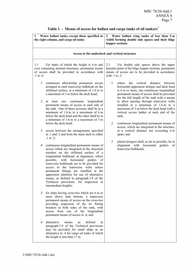
Table 1 - Means of access for ballast and cargo tanks of oil tankers* 1 Water ballast tanks, except those specified in the right column, and cargo oil tanks
2 Water ballast wing tanks of less than 5 m width forming double side spaces and their bilge hopper sections
Access to the underdeck and vertical structure
1.1 For tanks of which the height is 6 m and over containing internal structures, permanent means of access shall be provided in accordance with .1 to .6:
.1 continuous athwartship permanent access arranged at each transverse bulkhead on the stiffened surface, at a minimum of 1.6 m to a maximum of 3 m below the deck head;
.2 at least one continuous longitudinal
permanent means of access at each side of the tank. One of these accesses shall be at a minimum of 1.6 m to a maximum of 6 m below the deck head and the other shall be at a minimum of 1.6 m to a maximum of 3 m below the deck head;
.3 access between the arrangements specified
in .1 and .2 and from the main deck to either .1 or .2;
.4 continuous longitudinal permanent means of
access which are integrated in the structural member on the stiffened surface of a longitudinal bulkhead, in alignment, where possible, with horizontal girders of transverse bulkheads are to be provided for access to the transverse webs unless permanent fittings are installed at the uppermost platform for use of alternative means, as defined in paragraph 3.9 of the Technical provisions, for inspection at intermediate heights;
.5 for ships having cross-ties which are 6 m or
more above tank bottom, a transverse permanent means of access on the cross-ties providing inspection of the tie flaring brackets at both sides of the tank, with access from one of the longitudinal permanent means of access in .4; and
.6 alternative means as defined in
paragraph 3.9 of the Technical provisions may be provided for small ships as an alternative to .4 for cargo oil tanks of which the height is less than 17 m.
2.1 For double side spaces above the upper knuckle point of the bilge hopper sections, permanent means of access are to be provided in accordance with .1 to .3:
.1 where the vertical distance between horizontal uppermost stringer and deck head is 6 m or more, one continuous longitudinal permanent means of access shall be provided for the full length of the tank with a means to allow passing through transverse webs installed at a minimum of 1.6 m to a maximum of 3 m below the deck head with a vertical access ladder at each end of the tank;
.2 continuous longitudinal permanent means of
access, which are integrated in the structure, at a vertical distance not exceeding 6 m apart; and
.3 plated stringers shall, as far as possible, be in
alignment with horizontal girders of transverse bulkheads.

MSC 78/26/Add.1 ANNEX 8 Page 8
I:\MSC\78\26-Add.1.doc
1.2 For tanks of which the height is less than 6 m, alternative means as defined in paragraph 3.9 of the Technical provisions or portable means may be utilized in lieu of the permanent means of access.
2.2 For bilge hopper sections of which the vertical distance from the tank bottom to the upper knuckle point is 6 m and over, one longitudinal permanent means of access shall be provided for the full length of the tank. It shall be accessible by vertical permanent means of access at each end of the tank. 2.2.1 The longitudinal continuous permanent means of access may be installed at a minimum 1.6 m to maximum 3 m from the top of the bilge hopper section. In this case, a platform extending the longitudinal continuous permanent means of access in way of the webframe may be used to access the identified structural critical areas. 2.2.2 Alternatively, the continuous longitudinal permanent means of access may be installed at a minimum of 1.2 m below the top of the clear opening of the web ring allowing a use of portable means of access to reach identified structural critical areas.
Fore peak tanks 1.3 For fore peak tanks with a depth of 6 m or more at the centre line of the collision bulkhead, a suitable means of access shall be provided for access to critical areas such as the underdeck structure, stringers, collision bulkhead and side shell structure. 1.3.1 Stringers of less than 6 m in vertical distance from the deck head or a stringer immediately above are considered to provide suitable access in combination with portable means of access. 1.3.2 In case the vertical distance between the deck head and stringers, stringers or the lowest stringer and the tank bottom is 6 m or more, alternative means of access as defined in paragraph 3.9 of the Technical provisions shall be provided.
2.3 Where the vertical distance referred to in 2.2 is less than 6 m, alternative means as defined in paragraph 3.9 of the Technical provisions or portable means of access may be utilised in lieu of the permanent means of access. To facilitate the operation of the alternative means of access, in-line openings in horizontal stringers shall be provided. The openings shall be of an adequate diameter and shall have suitable protective railings.

MSC 78/26/Add.1 ANNEX 8
Page 9
I:\MSC\78\26-Add.1.doc
Table 2 - Means of access for bulk carriers* 1 Cargo holds
2 Ballast tanks
Access to underdeck structure 1.1 Permanent means of access shall be fitted to provide access to the overhead structure at both sides of the cross deck and in the vicinity of the centreline. Each means of access shall be accessible from the cargo hold access or directly from the main deck and installed at a minimum of 1.6 m to a maximum of 3 m below the deck. 1.2 An athwartship permanent means of access fitted on the transverse bulkhead at a minimum 1.6 m to a maximum 3 m below the cross-deck head is accepted as equivalent to 1.1. 1.3 Access to the permanent means of access to overhead structure of the cross deck may also be via the upper stool. 1.4 Ships having transverse bulkheads with full upper stools with access from the main deck which allows monitoring of all framing and plates from inside do not require permanent means of access of the cross deck. 1.5 Alternatively, movable means of access may be utilized for access to the overhead structure of the cross deck if its vertical distance is 17 m or less above the tank top.
Top side tanks 2.1 For each topside tank of which the height is 6 m and over, one longitudinal continuous permanent means of access shall be provided along the side shell webs and installed at a minimum of 1.6 m to a maximum of 3 m below deck with a vertical access ladder in the vicinity of each access to that tank. 2.2 If no access holes are provided through the transverse webs within 600 mm of the tank base and the web frame rings have a web height greater than 1 m in way of side shell and sloping plating, then step rungs/grab rails shall be provided to allow safe access over each transverse web frame ring. 2.3 Three permanent means of access, fitted at the end bay and middle bay of each tank, shall be provided spanning from tank base up to the intersection of the sloping plate with the hatch side girder. The existing longitudinal structure, if fitted on the sloping plate in the space may be used as part of this means of access. 2.4 For topside tanks of which the height is less than 6 m, alternative means as defined in paragraph 3.9 of the Technical provisions or portable means may be utilized in lieu of the permanent means of access.
Access to vertical structures 1.6 Permanent means of vertical access shall be provided in all cargo holds and built into the structure to allow for an inspection of a minimum of 25 % of the total number of hold frames port and starboard equally distributed throughout the hold including at each end in way of transverse bulkheads. But in no circumstance shall this arrangement be less than 3 permanent means of vertical access fitted to each side (fore and aft ends of hold and mid-span). Permanent means of vertical access fitted between two adjacent hold frames is counted for an access for the inspection of both hold frames. A means of portable access may be used to gain access over the sloping plating of lower hopper ballast tanks. 1.7 In addition, portable or movable means of access shall be utilized for access to the remaining hold frames up to their upper brackets and transverse bulkheads.
Bilge hopper tanks 2.5 For each bilge hopper tank of which the height is 6 m and over, one longitudinal continuous permanent means of access shall be provided along the side shell webs and installed at a minimum of 1.2 m below the top of the clear opening of the web ring with a vertical access ladder in the vicinity of each access to the tank. 2.5.1 An access ladder between the longitudinal continuous permanent means of access and the bottom of the space shall be provided at each end of the tank. 2.5.2 Alternatively, the longitudinal continuous permanent means of access can be located through the upper web plating above the clear opening of the web ring, at a minimum of 1.6 m below the deck head, when this arrangement facilitates more suitable inspection of identified structurally critical areas. An enlarged longitudinal frame can be used for the purpose of the walkway.

MSC 78/26/Add.1 ANNEX 8 Page 10
I:\MSC\78\26-Add.1.doc
1.8 Portable or movable means of access may be utilized for access to hold frames up to their upper bracket in place of the permanent means required in 1.6. These means of access shall be carried on board the ship and readily available for use. 1.9 The width of vertical ladders for access to hold frames shall be at least 300 mm, measured between stringers. 1.10 A single vertical ladder over 6 m in length is acceptable for the inspection of the hold side frames in a single skin construction. 1.11 For double-side skin construction no vertical ladders for the inspection of the cargo hold surfaces are required. Inspection of this structure should be provided from within the double hull space.
2.5.3 For double-side skin bulk carriers, the longitudinal continuous permanent means of access may be installed within 6 m from the knuckle point of the bilge, if used in combination with alternative methods to gain access to the knuckle point. 2.6 If no access holes are provided through the transverse ring webs within 600 mm of the tank base and the web frame rings have a web height greater than 1 m in way of side shell and sloping plating, then step rungs/grab rails shall be provided to allow safe access over each transverse web frame ring. 2.7 For bilge hopper tanks of which the height is less than 6 m, alternative means as defined in paragraph 3.9 of the Technical provisions or portable means may be utilized in lieu of the permanent means of access. Such means of access shall be demonstrated that they can be deployed and made readily available in the areas where needed. Double-skin side tanks 2.8 Permanent means of access shall be provided in accordance with the applicable sections of table 1.
Fore peak tanks 2.9 For fore peak tanks with a depth of 6 m or more at the centreline of the collision bulkhead, a suitable means of access shall be provided for access to critical areas such as the underdeck structure, stringers, collision bulkhead and side shell structure. 2.9.1 Stringers of less than 6 m in vertical distance from the deck head or a stringer immediately above are considered to provide suitable access in combination with portable means of access. 2.9.2 In case the vertical distance between the deck head and stringers, stringers or the lowest stringer and the tank bottom is 6 m or more, alternative means of access as defined in paragraph 3.9 of the Technical provisions shall be provided.
* For ore carriers, permanent means of access shall be provided in accordance with the applicable
sections of table 1 and table 2."
***

MSC 78/26/Add.1
I:\MSC\78\26-Add.1.doc
ANNEX 10
DRAFT AMENDMENT TO CHAPTER III OF THE INTERNATIONAL CONVENTION FOR THE SAFETY OF LIFE AT SEA, 1974, AS AMENDED
CHAPTER III
LIFE-SAVING APPLIANCES AND ARRANGEMENTS
Regulation 31 - Survival craft and rescue boats 1 The following new paragraph 1.8 is added after existing paragraph 1.7:
�1.8 Notwithstanding the requirements of paragraph 1.1, bulk carriers as defined in regulation IX/1.6 constructed on or after [�] shall comply with the requirements of paragraph 1.2.�
***
MSC 78/26/Add.1
I:\MSC\78\26-Add.1.doc
ANNEX 11
DRAFT MSC RESOLUTION
STANDARDS AND CRITERIA FOR SIDE STRUCTURES OF BULK CARRIERS OF SINGLE-SIDE SKIN CONSTRUCTION
THE MARITIME SAFETY COMMITTEE, RECALLING Article 28(b) of the Convention on the International Maritime Organization concerning the functions of the Committee, RECALLING ALSO SOLAS chapter XII on Additional safety measures for bulk carriers, which the 1997 SOLAS Conference adopted with the aim of enhancing the safety of ships carrying solid bulk cargoes, RECALLING FURTHER that, having recognized the need to further improve the safety of bulk carriers in all aspects of their design, construction, equipment and operation, it examined the results of various formal safety assessment (FSA) studies on bulk carrier safety,
RECOGNIZING that banning of alternate hold loading of heavy cargoes in full load condition for bulk carriers of single-side skin construction not meeting appropriate side structural strength requirements would contribute to improving the safety of these ships by reduction of shear forces and bending moments,
NOTING resolution MSC.[..](..) by which it adopted, inter alia, the revised chapter XII of the Convention, in particular regulation XII/14 � Restrictions from sailing with any hold empty, where reference is made to mandatory standards and criteria which a bulk carrier has to comply with in order to avoid the above-mentioned restrictions, ACKNOWLEDGING that the International Association of Classification Societies (IACS) has issued the following relevant Unified Requirements:
S12 Rev.2.1 - Side structure in Single Side Skin Bulk Carriers; and
S31 - Renewal criteria for side shell frames in single side skin bulk carriers not built in accordance with UR S12 Rev.1 or subsequent revisions,
CONSIDERING that the above IACS Unified Requirements embody respectively the standards and criteria necessary to ascertain whether regulation XII/14 of the Convention should apply to a particular bulk carrier, and, therefore, should form the basis of the said standards and criteria,
HAVING CONSIDERED the recommendation made by the Sub-Committee on Ship Design and Equipment at its forty-seventh session,

MSC 78/26/Add.1 ANNEX 11 Page 2
I:\MSC\78\26-Add.1.doc
1. ADOPTS, for the purposes of the application of regulation XII/14 of the Convention:
.1 the Standards for side structures in single-side skin bulk carriers, set out in Annex 1 to the present resolution; and
.2 the Renewal criteria for side shell frames and brackets in single-side skin bulk
carriers not built in accordance with the Standards for side structures in single-side skin bulk carriers, set out in Annex 2 to the present resolution;
2. INVITES Contracting Governments to the Convention to note that the annexed Standards and Renewal criteria will take effect on [����] upon the entry into force of the revised chapter XII of the Convention; 3. REQUESTS the Secretary-General to transmit certified copies of this resolution and the text of the annexed Standards and Renewal criteria to all Contracting Governments to the Convention; 4. FURTHER REQUESTS the Secretary-General to transmit certified copies of this resolution and the text of the annexed Standards and Renewal criteria to all Members of the Organization which are not Contracting Governments to the Convention.

MSC 78/26/Add.1 ANNEX 11
Page 3
I:\MSC\78\26-Add.1.doc
ANNEX 1
STANDARDS FOR SIDE STRUCTURES IN SINGLE-SIDE SKIN BULK CARRIERS
1 Application For the purpose of SOLAS regulation XII/14, these requirements define the minimum required standards for the side structures within the cargo area of single-side skin bulk carriers of 150 m in length and upwards carrying solid bulk cargoes having a density of 1,780 kg/m³ and above, for them not to be subject to restrictions from sailing with any hold empty. 2 Scantlings of side structures 2.1 The thickness of the side shell plating and the section modulus and shear area of side frames shall be determined according to the criteria of a classification society which is recognized by the Administration in accordance with the provisions of SOLAS regulation XI-1/1, or with applicable national standards of the Administration which provide an equivalent level of safety. 2.2 The scantlings of side hold frames immediately adjacent to the collision bulkhead shall be increased in order to prevent excessive imposed deformation on the shell plating. As an alternative, supporting structures shall be fitted which maintain the continuity of forepeak stringers within the foremost hold. 3 Minimum thickness of frame webs The thickness of frame webs within the cargo area shall not be less than tw,min, in mm, given by:
)L03.00.7(Ct min,w += where:
C = 1.15 for the frame webs in way of the foremost hold; 1.0 for the frame webs in way of other holds. L = the distance, in metres, on the summer load waterline from the fore side of stem to
the after side of the rudder post, or the centre of the rudder stock if there is no rudder post. L shall not be less than 96%, and need not be greater than 97%, of the extreme length on the summer load waterline but need not be taken greater than 200 m.
4 Lower and upper brackets
4.1 The thickness of the frame lower brackets shall not be less than the greater of tw and tw,min + 2 mm, where tw is the fitted thickness of the side frame web. The thickness of the frame upper bracket shall not be less than the greater of tw and tw,min.

MSC 78/26/Add.1 ANNEX 11 Page 4
I:\MSC\78\26-Add.1.doc
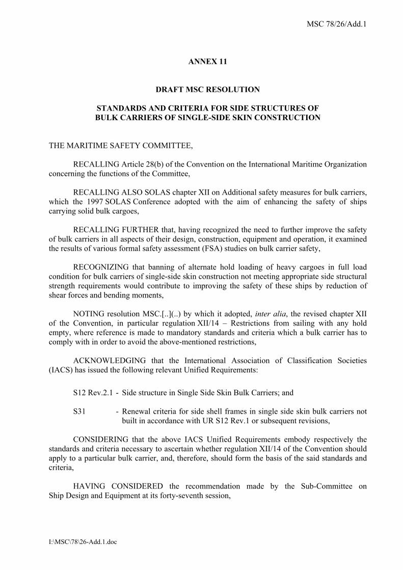
4.2 The section modulus SM of the frame and bracket or integral bracket, and associated shell plating, at the locations shown in Figure 1, shall not be less than twice the section modulus SMF required for the frame midspan area. 4.3 The dimensions of the lower and upper brackets shall not be less than those shown in Figure 2. 4.4 Structural continuity with the upper and lower end connections of side frames shall be ensured within topside and hopper tanks by connecting brackets as shown in Figure 3. The brackets shall be stiffened against buckling according to the criteria of a classification society which is recognized by the Administration in accordance with the provisions of SOLAS regulation XI-1/1, or with applicable national standards of the Administration which provide an equivalent level of safety. 4.5 The section moduli of the side longitudinals and sloping bulkhead longitudinals which support the connecting brackets shall be determined with the span taken between transverses according to the requirements of a classification society which is recognized by the Administration in accordance with the provisions of SOLAS regulation XI-1/1, or with applicable national standards of the Administration which provide an equivalent level of safety. Where other arrangements are adopted at the discretion of the Administration or a recognized classification society, the section moduli of the side longitudinals and sloping bulkhead longitudinals shall be determined according to the applicable criteria for the purpose of effectively supporting the brackets. 5 Side frame sections 5.1 Frames shall be fabricated symmetrical sections with integral upper and lower brackets and shall be arranged with soft toes. 5.2 The side frame flange shall be curved (not knuckled) at the connection with the end brackets. The radius of curvature shall not be less than r, in mm, given by:
f
2f
tb4.0r =
where bf and tf are the flange width and thickness of the brackets, respectively, in mm. The end of the flange shall be sniped. 5.3 In ships less than 190 m in length, mild steel frames may be asymmetric and fitted with separate brackets. The face plate or flange of the bracket shall be sniped at both ends. Brackets shall be arranged with soft toes.

MSC 78/26/Add.1 ANNEX 11
Page 5
I:\MSC\78\26-Add.1.doc
5.4 The frame web thickness ratio of frames shall not exceed the following values:
• 60 k0.5 for symmetrically flanged frames
• 50 k0.5 for asymmetrically flanged frames
where:
k = 1.0 for ordinary hull structural steel; k = 0.78 for steel with yield stress of 315 N/mm²; and k = 0.72 for steel with yield stress of 355 N/mm².
The outstanding flange shall not exceed 10 k0.5 times the net flange thickness. 6 Tripping brackets In way of the foremost hold side frames of asymmetrical section shall be fitted with tripping brackets at every two frames, as shown in Figure 4. 7 Weld connections of frames and end brackets 7.1 Double continuous welding shall be adopted for the connections of frames and brackets to side shell and hopper and upper wing tank plating and web to face plates. 7.2 For this purpose, the weld throat shall be (see Figure 1):
• 0.44 t in zone �a�
• 0.4 t in zone �b�
where t is the thinner of the two connected members. 7.3 Where the hull form is such to prohibit an effective fillet weld, edge preparation of the web of frame and bracket may be required, in order to ensure the same efficiency as the weld connection stated above. 8 Minimum net thickness of side shell plating The thickness of side shell plating located between the hopper and top wing tank shall not be less than tp,min in mm, given by:
Lt min,p =
MSC 78/26/Add.1 ANNEX 11 Page 6
I:\MSC\78\26-Add.1.doc
Figure 1

MSC 78/26/Add.1 ANNEX 11
Page 7
I:\MSC\78\26-Add.1.doc
Figure 2
Figure 3

MSC 78/26/Add.1 ANNEX 11 Page 8
I:\MSC\78\26-Add.1.doc
Figure 4 - Tripping brackets to be fitted in way of foremost hold
MSC 78/26/Add.1 ANNEX 11
Page 9
I:\MSC\78\26-Add.1.doc
ANNEX 2
RENEWAL CRITERIA FOR SIDE SHELL FRAMES AND BRACKETS IN SINGLE-SIDE SKIN BULK CARRIERS NOT BUILT IN ACCORDANCE WITH THE �STANDARDS FOR SIDE STRUCTURES IN SINGLE-SIDE SKIN BULK CARRIERS� 1 Application and definitions
For the purpose of SOLAS regulation XII/14, these requirements apply to the side shell frames and brackets of cargo holds in single-side skin bulk carriers, which were not built in accordance with annex 1, but shall achieve an equivalent level of safety for not being subject to restrictions when sailing with any hold empty. These requirements define steel renewal criteria or other measures to be taken for the webs and flanges of side shell frames and brackets as per paragraph 2. Reinforcing measures of side frames are also defined as per paragraph 2.3. Finite element or other numerical analysis or direct calculation procedures cannot be used as an alternative to compliance with the requirements of this annex, except in cases of unusual side structure arrangements or framing to which the requirements of this annex cannot be directly applied. Assessment of compliance with these requirements is to be carried out by the date on which the ship reaches 10 years of age and at each subsequent intermediate and renewal survey. 1.1 Ice strengthened ships 1.1.1 Where bulk carriers are reinforced to comply with an ice class notation, the intermediate frames shall not be included when considering compliance with this annex. 1.1.2 The renewal thicknesses for the additional structure required to meet the ice strengthening notation shall be based on the classification society�s requirements. 1.1.3 If the ice class notation is requested to be withdrawn, the additional ice strengthening structure, with the exception of tripping brackets (see 2.1.2.1.b and 2.3), shall not be considered to contribute to compliance with this annex.

MSC 78/26/Add.1 ANNEX 11 Page 10
I:\MSC\78\26-Add.1.doc
2 Renewal or other measures 2.1 Criteria for renewal or other measures 2.1.1 Symbols used in 2.1
tM = thickness as measured, in mm tREN = thickness at which renewal is required (2.1.2) tREN,d/t = thickness criteria based on d/t ratio (2.1.2.1) tREN,S = thickness criteria based on strength (2.1.2.2) tCOAT = 0.75 tS12 tS12 = thickness in mm as required by annex 1 in paragraph 3 for frame webs
and in paragraph 4 for upper and lower brackets tAB = thickness as built, in mm tC = See Table 1 below
Table 1 - tC values, in mm
Holds other than No. 1 Hold No. 1 Ship�s length L, in m Span and upper
brackets Lower brackets Span and upper brackets Lower brackets
≤100 2 2.5 2 3
150 2 3 3 3.5
≥ 200 2 3 3 4
Note: For intermediate ship lengths, tC is obtained by linear interpolation between the above values.
2.1.2 Criteria for webs (Shear and other checks) The webs of side shell frames and brackets shall be renewed when the measured thickness (tM) is equal to or less than the thickness (tREN) as defined below: tREN is the greatest of:
.1 tCOAT � tC
.2 0.75 tAB
.3 tREN,d/t
.4 tREN,S (where required by 2.1.2.2)

MSC 78/26/Add.1 ANNEX 11
Page 11
I:\MSC\78\26-Add.1.doc
2.1.2.1 Thickness criteria based on d/t ratio Subject to b) and c) below, tREN,d/t is given by the following equation:
tREN,d/t = (web depth in mm)/R where:
R = for frames
65 k0.5 for symmetrically flanged frames 55 k0.5 for asymmetrically flanged frames
for lower brackets (see a) below):
87 k0.5 for symmetrically flanged frames 73 k0.5 for asymmetrically flanged frames
k = 1 for ordinary hull structural steel, k = 0.78 for steel with yield stress of 315 N/mm² and k = 0.72 for steel with yield stress of 355 N/mm².
In no instance shall tREN,d/t for lower integral brackets be taken as less than tREN,d/t for the frames they support.
a) Lower brackets
In calculating the web depth of the lower brackets, the following shall apply:
.1 The web depth of lower bracket may be measured from the intersection of the sloped bulkhead of the hopper tank and the side shell plate, perpendicularly to the face plate of the lower bracket (see Figure 3).
.2 Where stiffeners are fitted on the lower bracket plate, the web depth may
be taken as the distance between the side shell and the stiffener, between the stiffeners or between the outermost stiffener and the face plate of the brackets, whichever is the greatest.
b) Tripping bracket alternative
When tM is less than tREN,d/t at section b) of the side frames (see figure 2), tripping
brackets in accordance with 2.3 may be fitted as an alternative to the requirements for the web depth to thickness ratio of side frames, in which case tREN,d/t may be disregarded in the determination of tREN in accordance with 2.1.2.

MSC 78/26/Add.1 ANNEX 11 Page 12
I:\MSC\78\26-Add.1.doc
c) Immediately abaft collision bulkhead
For the side frames located immediately abaft the collision bulkhead, whose scantlings are increased in order that their moment of inertia is such as to avoid undesirable flexibility of the side shell, when their web as built thickness tAB is greater than 1.65tREN,S, the thickness tREN,d/t may be taken as the value t�REN,d/t obtained from the following equation:
3
S,REN2
t/d,RENt/d,REN tt't =
where tREN,S is obtained from 3.3.
2.1.2.2 Thickness criteria based on shear strength check Where tM in the lower part of side frames, as defined in Figure 1, is equal to or less than tCOAT, tREN,S shall be determined in accordance with 3.3. 2.1.2.3 Thickness of renewed webs of frames and lower brackets Where steel renewal is required, the renewed webs shall be of a thickness not less than tAB, 1.2tCOAT or 1.2tREN, whichever is the greatest. 2.1.2.4 Criteria for other measures When tREN < tM ≤ tCOAT, measures shall be taken, consisting of all the following:
.1 sand blasting, or equivalent, and coating (see 2.2),
.2 fitting tripping brackets (see 2.3), when the above condition occurs for any of the side frame zones A, B, C and D, shown in figure 1, and
.3 maintaining the coating in "as new" condition (i.e. without breakdown or rusting)
at renewal and intermediate surveys. The above measures may be waived if the structural members show no thickness diminution with respect to the as built thicknesses and coating is in "as new" condition (i.e. without breakdown or rusting). 2.1.3 Criteria for frames and brackets (Bending check) Where the length or depth of the lower bracket does not meet the requirements in annex 1, a bending strength check in accordance with 3.4 shall be carried out and renewals or reinforcements of frames and/or brackets effected as required therein. 2.2 Thickness measurements, steel renewal, sand blasting and coating For the purpose of steel renewal, sand blasting and coating, four zones A, B, C and D are defined, as shown in figure 1.

MSC 78/26/Add.1 ANNEX 11
Page 13
I:\MSC\78\26-Add.1.doc
Representative thickness measurements shall be taken for each zone and shall be assessed against the criteria in 2.1. In case of integral brackets, when the criteria in 2.1 are not satisfied for zone A or B, steel renewal, sand blasting and coating, as applicable, shall be done for both zones A and B. In case of separate brackets, when the criteria in 2.1 are not satisfied for zone A or B, steel renewal, sand blasting and coating shall be done for each one of these zones, as applicable. When steel renewal is required for zone C according to 2.1, it shall be done for both zones B and C. When sand blasting and coating is required for zone C according to 2.1, it shall be done for zones B, C and D. When steel renewal is required for zone D according to 2.1, it needs only to be done for this zone. When sand blasting and coating is required for zone D according to 2.1, it shall be done for both zones C and D. Special consideration may be given to zones previously renewed or re-coated, if found in �as new� condition (i.e., without breakdown or rusting) by the Administration or a classification society which is recognized by the Administration in accordance with the provisions of SOLAS regulation XI-1/1. When adopted, on the basis of the renewal thickness criteria in 2.1, in general coating shall be applied in compliance with the requirements of the organization, as applicable. Where, according to the requirements in 2.1, a limited number of side frames and brackets are shown to require coating over part of their length, the following criteria apply:
.1 The part to be coated includes:
- the web and the face plate of the side frames and brackets,
- the hold surface of side shell, hopper tank and topside tank plating, as applicable, over a width not less than 100 mm from the web of the side frame.
.2 Epoxy coating or equivalent shall be applied.
In all cases, all the surfaces to be coated shall be sand blasted prior to coating application. 2.3 Reinforcing measures Reinforcing measures are constituted by tripping brackets, located at the lower part and at midspan of side frames (see figure 4). Tripping brackets may be located at every two frames, but lower and midspan brackets shall be fitted in line between alternate pairs of frames. The thickness of the tripping brackets shall be not less than the as built thickness of the side frame webs to which they are connected.

MSC 78/26/Add.1 ANNEX 11 Page 14
I:\MSC\78\26-Add.1.doc
Double continuous welding shall be adopted for the connections of tripping brackets to the side shell frames and shell plating. 2.4 Weld throat thickness In case of steel renewal the welded connections shall comply with paragraph 7 of annex 1. 2.5 Pitting and grooving If pitting intensity is higher than 15% in area (see figure 5), thickness measurement shall be taken to check pitting corrosion. The minimum acceptable remaining thickness in pits or grooves is equal to:
.1 75% of the as built thickness, for pitting or grooving in the frame and brackets webs and flanges; and
.2 70% of the as built thickness, for pitting or grooving in the side shell, hopper tank
and topside tank plating attached to the side frame, over a width up to 30 mm from each side of it.
3 Strength check criteria In general, loads shall be calculated and strength checks shall be carried out for the aft, middle and forward frames of each hold. The scantlings required for frames in intermediate positions shall be obtained by linear interpolation between the results obtained for the above frames. When scantlings of side frames vary within a hold, the required scantlings shall also be calculated for the mid frame of each group of frames having the same scantlings. The scantlings required for frames in intermediate positions shall be obtained by linear interpolation between the results obtained for the calculated frames. 3.1 Load model 3.1.1 Forces The forces Pfr,a and Pfr,b, in kN, to be considered for the strength checks at sections a) and b) of side frames (specified in figure 2; in the case of separate lower brackets, section b) is at the top of the lower bracket), are given by: Pfr,a = PS + max (P1, P2)
Pfr,b = Pfr,a hh2h B−

MSC 78/26/Add.1 ANNEX 11
Page 15
I:\MSC\78\26-Add.1.doc
where:
Ps = still water pressure force, in kN
=
+2
pphs L,SU,S when the upper end of the side frame span h (see figure 1)
is below the load water line
=
2
p'hs L,S when the upper end of the side frame span h (see figure 1)
is at or above the load water line
P1 = wave pressure force, in kN, in head seas
=
+2
pphs L,1U,1
P2 = wave pressure force, in kN, in beam seas
=
+2
pphs L,2U,2
h, hB = side frame span and lower bracket length, in m, defined in figures 1 and 2,
respectively
h� = distance, in m, between the lower end of side frame span h (see figure 1) and
the load waterline
s = frame spacing, in m
pS,U, pS,L = still water pressure, in kN/m2, at the upper and lower end of the side frame span h (see figure 1), respectively
p1,U, p1,L = wave pressure, in kN/m2, as defined in 3.1.2.1 below for the upper
and lower end of the side frame span h, respectively
p2,U, p2,L = wave pressure, in kN/m2, as defined in 3.1.2.2 below for the upper
and lower end of the side frame span h, respectively
MSC 78/26/Add.1 ANNEX 11 Page 16
I:\MSC\78\26-Add.1.doc
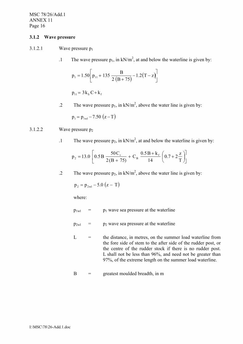
3.1.2 Wave pressure 3.1.2.1 Wave pressure p1
.1 The wave pressure p1, in kN/m2, at and below the waterline is given by:
( ) ( )
−−
++= zT2.1
75B2B135p50.1p 111
fS11 kCk3p +=
.2 The wave pressure p1, in kN/m2, above the water line is given by:
( )Tz50.7pp wl11 −−=
3.1.2.2 Wave pressure p2
.1 The wave pressure p2, in kN/m2, at and below the waterline is given by:
+
++
+=
Tz27.0
14kB5.0
C)75B(2
C50B5.00.13p f
Br
2
.2 The wave pressure p2, in kN/m2, above the water line is given by:
( )Tz0.5pp wl22 −−=
where:
p1wl = p1 wave sea pressure at the waterline
p2wl = p2 wave sea pressure at the waterline
L = the distance, in metres, on the summer load waterline from
the fore side of stem to the after side of the rudder post, or the centre of the rudder stock if there is no rudder post. L shall not be less than 96%, and need not be greater than 97%, of the extreme length on the summer load waterline.
B = greatest moulded breadth, in m

MSC 78/26/Add.1 ANNEX 11
Page 17
I:\MSC\78\26-Add.1.doc
CB = moulded block coefficient at draught d corresponding to summer load waterline, based on length L and moulded breadth B, but not to be taken less than 0.6:
LBdddraughtat³]m[ntdisplacememouldedCB =
T = maximum design draught, in m
C = coefficient
= 5.1
100L30075.10
−
− for 90 ≤ L ≤ 300 m
= 10.75 for 300 < L
Cr = (1.25 � 0.025 GMk2 r ) k
k = 1.2 for ships without bilge keel
= 1 for ships with bilge keel
kr = roll radius of gyration. If the actual value of kr is not
available
= 0.39 B for ships with even distribution of mass in transverse section (e.g. alternate heavy cargo loading or homogeneous light cargo loading)
= 0.25 B for ships with uneven distribution of mass in
transverse section (e.g. homogenous heavy cargo distribution)
GM = 0.12 B if the actual value of GM is not available
z = vertical distance, in m, from the baseline to the load point
ks = B
B CC 83.0
+ at aft end of L
= CB between 0.2 L and 0.6 L from aft end of L
= B
B CC 33.1
+ at forward end of L
Between the above specified points, ks shall be varied linearly
kf = 0.8 C

MSC 78/26/Add.1 ANNEX 11 Page 18
I:\MSC\78\26-Add.1.doc
3.2 Allowable stresses The allowable normal and shear stresses σa and τa, in N/mm2, in the side shell frames are given by:
σa = 0.90 σF τa = 0.40 σF
where σF is the minimum upper yield stress, in N/mm2, of the material. 3.3 Shear strength check Where tM in the lower part of side frames, as defined in figure 1, is equal to or less than tCOAT, shear strength check shall be carried out in accordance with the following. The thickness tREN,S, in mm, is the maximum between the thicknesses tREN,Sa and tREN,Sb obtained from the shear strength check at sections a) and b) (see figure 2 and 3.1) given by the following, but need not be taken in excess of 0.75tS12:
.1 at section a): aa
a,frSSa,REN sind
Pk000,1t
τφ=
.2 at section b): ab
b,frSSb,REN sind
Pk000,1t
τφ=
where:
ks = shear force distribution factor, to be taken equal to 0.6
Pfr,a, Pfr,b = pressure forces defined in 3.1.1
da, db = bracket and frame web depth, in mm, at sections a) and b), respectively (see figure 2); in case of separate (non integral) brackets, db shall be taken as the minimum web depth deducting possible scallops
φ = angle between frame web and shell plate
τa = allowable shear stress, in N/mm2, defined in 3.2.

MSC 78/26/Add.1 ANNEX 11
Page 19
I:\MSC\78\26-Add.1.doc
3.4 Bending strength check 1 When the lower bracket length or depth do not comply with requirements in annex 1, the actual section modulus, in cm3, of the brackets and side frames at sections a) and b) shall be not less than:
.1 at section a):
aa
a,fra m
hP000,1Z
σ=
.2 at section b):
ab
a,frb m
hP000,1Z
σ=
where:
Pfr,a = pressure force defined in 3.1.1
h = side frame span, in m, defined in figure 1
σa = allowable normal stress, in N/mm2, defined in 3.2
ma, mb = bending moment coefficients defined in table 2 2 The actual section modulus of the brackets and side frames shall be calculated about an axis parallel to the attached plate, based on the measured thicknesses. For pre-calculations, alternative thickness values may be used, provided they are not less than:
.1 tREN, for the web thickness;
.2 the minimum thicknesses allowed by the renewal criteria for flange and attached plating of a classification society which is recognized by the Administration in accordance with the provisions of SOLAS regulation XI-1/1, or by applicable national standards of the Administration which provide an equivalent level of safety.
3 The attached plate breadth is equal to the frame spacing, measured along the shell at midspan h. 4 If the actual section moduli at sections a) and b) are less than the values Za and Zb, the frames and brackets shall be renewed or reinforced in order to obtain actual section moduli not less than 1.2 Za and 1.2 Zb, respectively. In such a case, renewal or reinforcements of the flange shall be extended over the lower part of side frames, as defined in figure 1.

MSC 78/26/Add.1 ANNEX 11 Page 20
I:\MSC\78\26-Add.1.doc
Table 2 � Bending moment coefficients ma and mb
ma mb
hB = 0.08 h hB = 0.1 h hB = 0.125 h
Empty holds of ships approved to operate in non homogeneous loading conditions 10 17 19 22
Other cases 12 20 22 26
Note 1: Non homogeneous loading condition means a loading condition in which the ratio between the highest and the lowest filling ratio, evaluated for each hold, exceeds 1.20 corrected for different cargo densities.
Note 2: For intermediate values of the bracket length hB, the coefficient mb is obtained by linear interpolation between the table values.
Figure 1 � Lower part of side frames

MSC 78/26/Add.1 ANNEX 11
Page 21
I:\MSC\78\26-Add.1.doc
Figure 2 � Sections a) and b)
Figure 3 � Definition of the lower bracket web depth

MSC 78/26/Add.1 ANNEX 11 Page 22
I:\MSC\78\26-Add.1.doc
Figure 4 � Tripping brackets
Figure 5 - Pitting intensity diagrams (from 5% to 25% intensity)
***

MSC 78/26/Add.1
I:\MSC\78\26-Add.1.doc
ANNEX 12
DRAFT MSC RESOLUTION
STANDARDS FOR OWNERS� INSPECTION AND MAINTENANCE OF BULK CARRIER HATCH COVERS
THE MARITIME SAFETY COMMITTEE, RECALLING Article 28(b) of the Convention on the International Maritime Organization concerning the functions of the Committee, RECALLING ALSO SOLAS chapter XII on Additional safety measures for bulk carriers, which the 1997 SOLAS Conference adopted with the aim of enhancing the safety of ships carrying solid bulk cargoes, RECALLING FURTHER that, having recognized the need to further improve the safety of bulk carriers in all aspects of their design, construction, equipment and operation, it examined the results of various formal safety assessment (FSA) studies on bulk carrier safety,
RECOGNIZING that, on the basis of the outcome of the aforementioned FSA studies, replacing hatch covers in existing bulk carriers would not be cost-effective and that, instead, more attention should be paid to hatch cover securing mechanisms and the issue of horizontal loads, especially with regard to maintenance and frequency of inspection,
RECALLING that, at its seventy-seventh session, in approving MSC/Circ.1071 � Guidelines for bulk carrier hatch cover surveys and owners� inspections and maintenance, it invited Member Governments to ensure that companies, as defined in the ISM Code, that operate bulk carriers flying their flag are made aware of the need to implement regular maintenance and inspection procedures for hatch cover closing mechanisms in existing bulk carriers in order to ensure proper operation and efficiency at all times,
HAVING APPROVED, with a view to adoption, draft amendments to regulation XII/7 of the Convention � Survey and maintenance of bulk carriers, where reference is made to mandatory Standards for owners� inspection and maintenance of bulk carrier hatch covers, HAVING CONSIDERED the recommendation made by the Sub-Committee on Ship Design and Equipment at its forty-seventh session, 1. ADOPTS, for the purposes of the application of regulation XII/7 of the Convention, the Standards for owners� inspection and maintenance of bulk carrier hatch covers, set out in the Annex to the present resolution; 2. INVITES Contracting Governments to the Convention to note that the annexed Standards will take effect on [����] upon the entry into force of the revised chapter XII of the Convention;

MSC 78/26/Add.1 ANNEX 12 Page 2
I:\MSC\78\26-Add.1.doc
3. REQUESTS the Secretary-General to transmit certified copies of this resolution and the text of the annexed Standards to all Contracting Governments to the Convention; 4. FURTHER REQUESTS the Secretary-General to transmit certified copies of this resolution and the text of the annexed Standards to all Members of the Organization which are not Contracting Governments to the Convention.

MSC 78/26/Add.1 ANNEX 12
Page 3
I:\MSC\78\26-Add.1.doc
ANNEX
STANDARDS FOR OWNERS� INSPECTION AND MAINTENANCE OF
BULK CARRIER HATCH COVERS 1 Application These Standards define requirements for the owners� inspection and maintenance of cargo hatch covers on board bulk carriers. 2 Maintenance of hatch covers and hatch opening, closing, securing and sealing
systems 2.1 Lack of weather tightness may be attributed to:
.1 normal wear and tear of the hatch cover system: deformation of the hatch coaming or cover due to impact; wear of the friction pads where fitted; wear and tear of the cleating arrangement; or
.2 lack of maintenance: corrosion of plating and stiffeners due to breakdown of
coatings; lack of lubrication of moving parts; cleats, joint gaskets and rubber pads in need of replacement, or replaced with incorrect specification parts.
2.2 Insecure hatch covers may be particularly attributed to damage or wear of securing devices, or incorrect adjustment, and incorrect pre-tension and load sharing, of cleating systems. 2.3 Ship owners and operators shall therefore institute a programme of maintenance. This maintenance shall be directed to:
.1 protecting exposed surfaces of plating and stiffeners of hatch covers and coamings in order to preserve overall structural strength;
.2 preserving the surface of trackways of rolling covers, and of compression bars and
other steel work bearing on seals or friction pads, noting that surface smoothness and correct profile are important for reducing wear rates on these components;
.3 maintaining hydraulic or mechanically powered opening, closing, securing or
cleating systems in accordance with manufacturer�s recommendations;
.4 maintaining manual cleats in adjustment, with replacement when significant
wastage, wear or loss of adjustment capability is identified;
.5 replacing seals and other wear components in accordance with manufacturers�
recommendations, noting the need to carry on board or obtain such spares of correct specification, and that seals are designed for a particular degree of compression, hardness, chemical and wear resistance; and

MSC 78/26/Add.1 ANNEX 12 Page 4
I:\MSC\78\26-Add.1.doc
.6 keeping all hatch cover drains and their non-return valves, where fitted, in working
order, noting that any drains fitted to the inboard side of seal lines will have non-return valves for prevention of water ingress to holds in the event of boarding seas.
2.4 The equalization of securing loads shall be maintained following the renewal of components such as seals, rubber washers, peripheral and cross joint cleats. 2.5 Ship owners and operators shall keep a Maintenance Plan and a record of maintenance and component replacement carried out, in order to facilitate maintenance planning and statutory surveys by the Administration. Hatch cover maintenance plans shall form part of a ship�s safety management system as referred to in the ISM Code. 2.6 Where the range of cargoes carried requires different gasket materials, a selection of gasket materials of the correct specifications shall be carried on board, in addition to other spares. 2.7 At each operation of a hatch cover, the cover, and in particular bearing surfaces and drainage channels, shall be free of debris and as clean as practicable. 2.8 Attention is drawn to the dangers of proceeding to sea without fully secured hatch covers. Securing of all covers shall always be completed before the commencement of a sea passage. During voyages, especially on loaded passages, cover securing devices and tightness of cleating and securing arrangements shall be checked, especially in anticipation of, and following periods of, severe weather. Hatch covers may only be opened on passage, when necessary, during favourable sea and weather conditions; imminent weather forecasts shall also be considered. 2.9 Operators shall consult the Cargo Securing Manual when planning the loading of containers or other cargo on hatch covers and confirm that they are designed and approved for such loads. Lashings shall not be secured to the covers or coamings unless these are suitable to withstand the lashing forces. 3 Inspection of hatch covers and hatch opening, closing, securing and sealing systems 3.1 Statutory surveys of hatch covers and their coamings are carried out by the Administration as part of the annual survey required by article 14 of the International Convention on Load Lines, 1966, as modified by the 1988 Protocol relating thereto and in accordance with the requirements for Enhanced Surveys contained in resolution A.744(18), as amended. However the continued safe operation is dependent on the shipowner or operator instituting a regular programme of inspections to confirm the state of the hatch covers in between surveys. 3.2 Routines shall be established to perform checks during the voyage, and inspections when the hatch covers are opened. 3.3 Voyage checks shall consist of an external examination of the closed hatch covers and securing arrangements in anticipation of, and after, heavy weather but in any event at least once a week, weather permitting. Particular attention shall be paid to the condition of hatch covers in the forward 25% of the ship�s length, where sea loads are normally greatest.

MSC 78/26/Add.1 ANNEX 12
Page 5
I:\MSC\78\26-Add.1.doc
3.4 The following items, where provided, shall be inspected for each hatch cover set when the hatch covers are opened or are otherwise accessible on each voyage cycle, but need not be inspected more frequently than once per month:
.1 hatch cover panels, including side plates, and stiffener attachments of opened covers for visible corrosion, cracks or deformation;
.2 sealing arrangements of perimeter and cross joints (gaskets, flexible seals on
combination carriers, gasket lips, compression bars, drainage channels and non-return valves) for condition and permanent deformation;
.3 clamping devices, retaining bars and cleating for wastage, adjustment, and
condition of rubber components;
.4 closed cover locating devices for distortion and attachment;
.5 chain or wire rope pulleys;
.6 guides;
.7 guide rails and track wheels;
.8 stoppers;
.9 wires, chains, tensioners and gypsies;
.10 hydraulic system, electrical safety devices and interlocks; and
.11 end and inter-panel hinges, pins and stools where fitted. As part of this inspection, the coamings with their plating, stiffeners and brackets shall be checked at each hatchway for visible corrosion, cracks and deformation, especially of the coaming tops and corners, adjacent deck plating and brackets.
***


