ANILAM - ACU-RITE 3000M 3 Axis Training Guide. Bookmarks Navigation Instructions Follow the...
132
ANILAM 3000M 3 Axis Training Guide
Transcript of ANILAM - ACU-RITE 3000M 3 Axis Training Guide. Bookmarks Navigation Instructions Follow the...
ANILAM 3000M 3 Axis Training Guide

Navigation InstructionsBookmarks
Follow the bookmarks at the left sideof the page to navigate to desired topic
Click plus and minus symbols to expandand compress menu display

3000M CNC ControlTraining Guide

Turning the Control ON
1
After the control has been turned ON press F10 to continue.
Then press to select next page
F10
Select
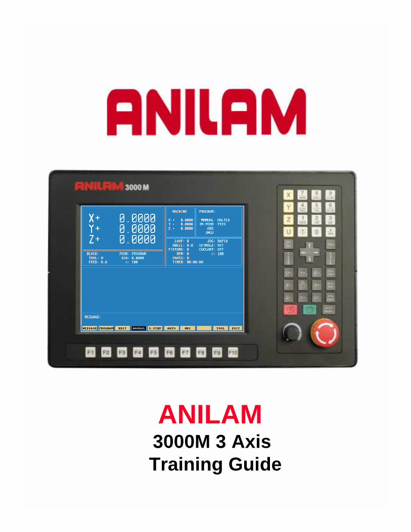
Main Areas of the Display
2
Programmed PositionMachine Position
from Home Machine Status
Message AreaProgram & Tool
information
Auxiliary FunctionsInformation

3
Areas of Main Screen
Program Name
Mode of machineManual , Single Step or Auto
Condition of machine
Type of moveabs/inc
UnitsInch/MM
Type of movementRapid or Feed
Halted or Running
Type of Manual movementRapid,Feed,100,10 or 1
Spindle ConditionFWD,REV or OFF
Coolant conditionON or OFF
Number of loopsremaining to be done
Time leftto Dwell
Active FixtureOffset
Spindle Speed
Number or partproduced
Running Time
Active line in Auto
Active Tool
Actual Feedrate
Posn:Program or Dist to go
Tool Dia fromTool Page
Percentage of programmedFeedrate

4
KeyboardKeyboardKeyboardKeyboard
7 and UnitInch/MM.
8 and Dwell key
9 and Plane keyXY,XZ & YZ.
Axis keys
4 and Feed key
5 and Tool mount key
6 and Mcode key
3 and Arc key2 and Line key
1 and Rapid key
. And RPM key
0 and display positionCalculalator
EnterSpindle command keys
Servo reset key
Start key
Emergency stopButton
Plus/minus key
Absolute/Increamental key
Cursor movement key
Clear key
Jog Mode Change key
Axis jog keys
Hold key
Feedrate override knob
All the number key and the decimal point have duel functions as show above.

1Rapid
Along with the above we have “Hot Keys”
2Line
3Arc
6MCode
Accesses Rapid menus.
Accesses Line menus.
Accesses Arc menus.
Input feedrate.
Tool mount.
Mcode inputs.
Inch/MM
Dwell in seconds
Changes from XY,XZ or YZ.
If * put in front of line in program ignores that line.
Input for spindle speed if available.
5
RPM
0*
9Plane
8Dwell
7Unit
5Tool
4Feed
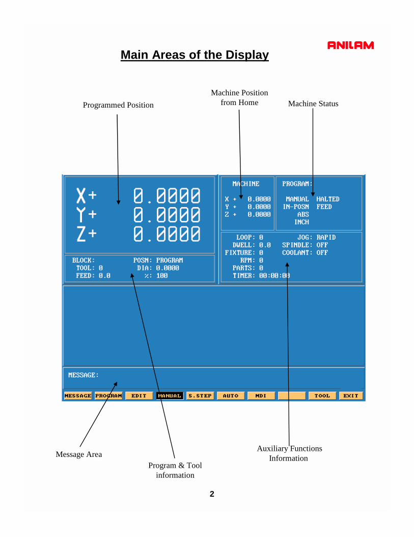
Function Keys
6
The Function (or F keys) activate the Mode shown directly above on the Display screen.The meaning of F keys change, depending upon what Mode of operation is selected.
F9F2 F3 F7F5 F8F6
An example of how F keys is shown above,this is how it would change when going from Manual to in Single Step or Auto.
F1 F4 F10
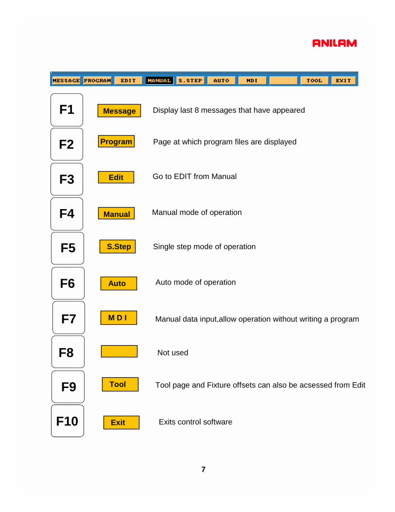
7
Display last 8 messages that have appeared
Page at which program files are displayed
Go to EDIT from Manual
Manual mode of operation
Single step mode of operation
Auto mode of operation
Manual data input,allow operation without writing a program
Not used
Tool page and Fixture offsets can also be acsessed from Edit
Exits control software
F1
F10
F2
F4
F5
F6
F7
F8
F9
F3
Message
Program
Edit
Manual
S.Step
Auto
M D I
Tool
Exit

8
F1 Message Page
This is how the messages will appear on the screen .When control is turned off the messages will be erased.
This is useful to tech’s when trouble shooting problems on the control
To enter message page press MessageF1

9
Program Page
Exit
Create
To enter page Press F2 Program
F10
F3
F4
F5
F6
F7
F8
F9
F1
F2
Not used
Delete
Edit
List
Select
Log
Display
Utility
This where new program names are type in.
Delete an existing program.
Programs are written and changed.
Allows you to look at program but no Editing .
Picks program to be run.
Changes disk drive.
Changes how program page display program list
Contains such utility as Copy ,Rename etc.
Return to main screen in Manual Mode

10
ENTER
Create
again and press enter, this will put program into the list of programs with .M extension and
Using the arrow keys pick the letters then press the enter key.When complete press ASCII
When ASCII is pressed, this how the soft keys will look and a table will appear as show below
highlight will be on program that was just created.

11
When is press, the screen appear as shown below.Edit
Edit
ListPressing allows user to look you to look at program only.

12
Program that is highlighted and then selected will shows up in this area.A program may be edited without being selected , but not run in Single step or auto.
Select

13
Display
Normal screen only show .m files
Press display one time it will change todisplay all files in directory
Show only .m files but show size of program,date and time written
Show all in program files but show size ofpage program,date and time written
14
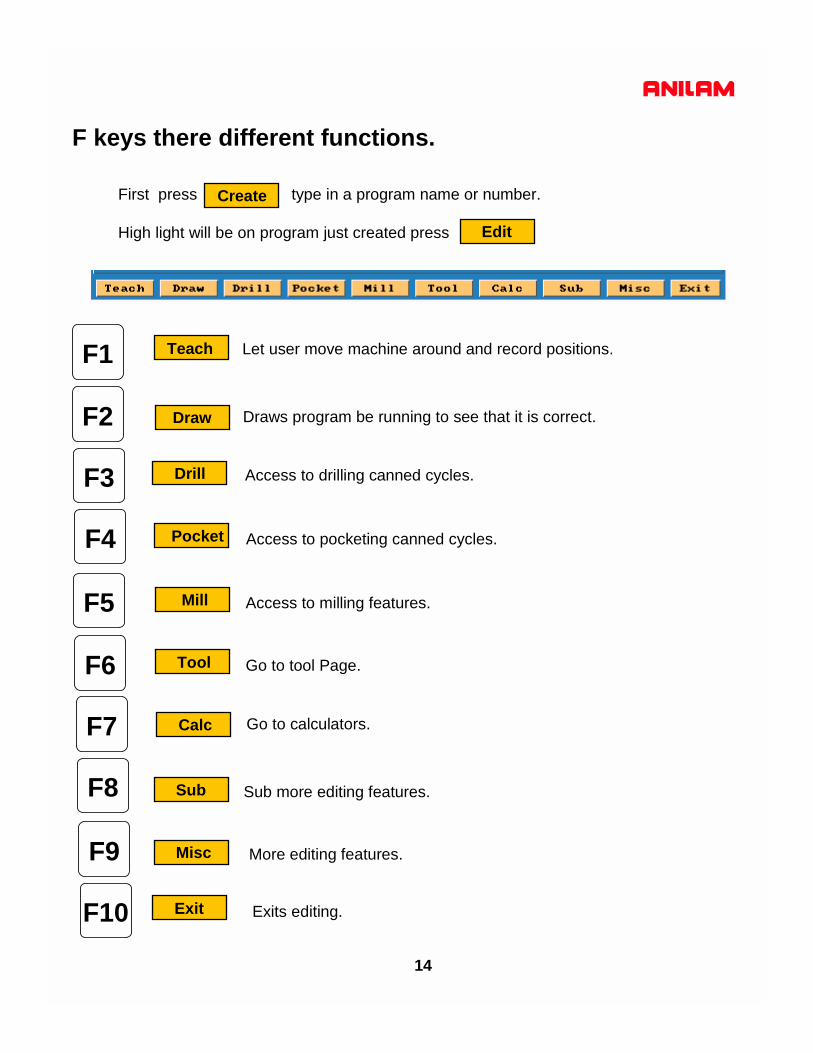
F keys there different functions.
CreateFirst press type in a program name or number.
High light will be on program just created press Edit
F1
F2
F6
F7
F8
F9
F10
Let user move machine around and record positions.
Draws program be running to see that it is correct.
Access to drilling canned cycles.
Access to pocketing canned cycles.
Access to milling features.
Go to tool Page.
Go to calculators.
Sub more editing features.
Draw
Teach
F3 Drill
F4 Pocket
F5 Mill
Tool
Calc
Sub
Misc
Exit
More editing features.
Exits editing.
15
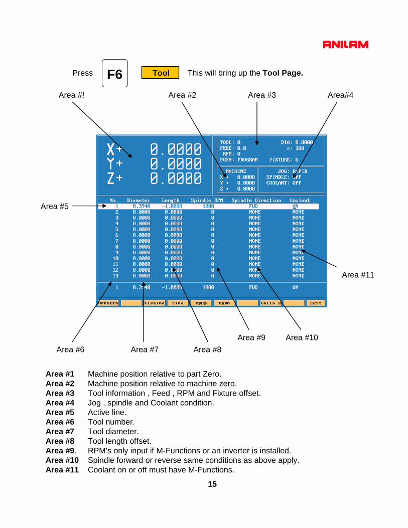
F6 ToolPress This will bring up the Tool Page.
Area #! Area #2 Area #3
Area #6 Area #7 Area #8Area #9 Area #10
Area #11
Area#4
Area #5
Area #1 Machine position relative to part Zero.Area #2 Machine position relative to machine zero.Area #3 Tool information , Feed , RPM and Fixture offset.Area #4 Jog , spindle and Coolant condition.Area #5 Active line.Area #6 Tool number.Area #7 Tool diameter.Area #8 Tool length offset. Area #9. RPM’s only input if M-Functions or an inverter is installed.Area #10 Spindle forward or reverse same conditions as above apply.Area #11 Coolant on or off must have M-Functions.
16
F1
F2
F6
F7
F8
F9
F10
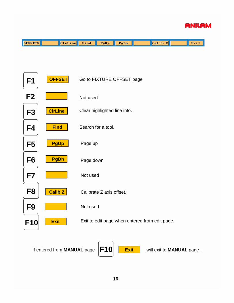
OFFSET
F3 ClrLine
F4 Find
F5 PgUp
PgDn
Calib Z
Exit
Go to FIXTURE OFFSET page
Not used
Not used
Not used
Clear highlighted line info.
Search for a tool.
Page up
Page down
Calibrate Z axis offset.
Exit to edit page when entered from edit page.
If entered from MANUAL page will exit to MANUAL page .F10 Exit

17
F1 OFFSETPress this will take you to offset page.
All entries are taken from Machine Home.
Entries may be entered manually or by using CalibX or CalibY.
When doing manual input , select axis you wise to enter a value , by pressing that axis keyand input number require press ENTER.
Using the Calib key move to required position and press desired calib axis key.
F10 ExitPress to return to Tool Page
F10 ExitPress to return to Manual Page

Enter adjustment value is an added feature that allows altering of existing values inthe tool page or fixture offsets display. Use the ABS/INC Key to activate this feature.
Example: Altering tool diameter using Enter adjustment value.* Asterisk highlights the selected value.
Example: Altering fixture offsets using Enter axis and adjustment value
3000M CNC ControlLines and Arcs

Lines and Arcs
Lines and arcs can be access in two ways .1. Using hot keys.
2.Using soft keys
Press
Press
Press
1Rapid
2Line
3Arc
Accesses Rapid menus.
Accesses Line menus.
Accesses Arc menus.
F5 Mill
F2 Rapid
F4 More...
1.

2.
Screen will now show 6 icons , these apply to both rapid and line moves.
Line and Rapid are the same with one exception CornerRad and feed are not in rapid.
1. Enter coordinates in any or all axis.
3.
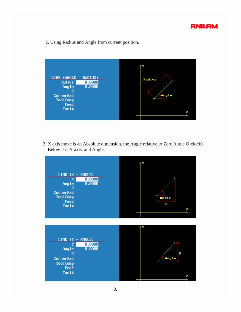
2. Using Radius and Angle from current position.
3. X axis move is an Absolute dimension, the Angle relative to Zero (three O’clock).Below it is Y axis and Angle.

4.
4.Axis and AngleIf programming absolute X or Y dimension is from Part 0 and radius is from currentposition.If programming incremental X or Y dimension and radius are from current position.

The icon below are for arcs.
1 2 3
Tool must be at start point of arc before it is programmed.Arc may be cut in any plane but must selected, default is XY.
5.
F5 Mill
F4 Arc
F4 More...

6.
2. With this arc it is possible to mill a thread . Enter X Y and Z end point , X Y center point and Number of Revolutions.The pitch of thread is controlled by the Z movement and the number of revolutions.
1.This is the default arc , End points for 2 axis and radius.Direction is changed by pressing +/- key.If programming an arc over 180 deg the radius is enteredas a minus (-) value.
6.
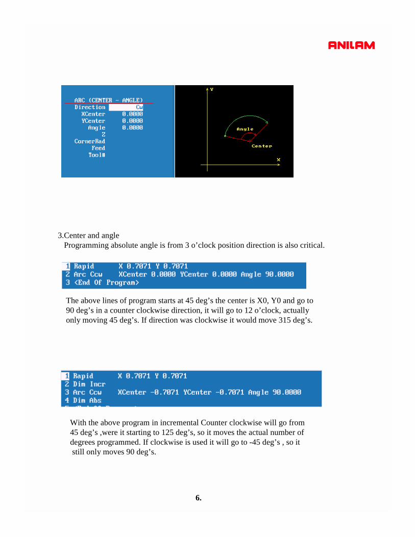
3.Center and angleProgramming absolute angle is from 3 o’clock position direction is also critical.
The above lines of program starts at 45 deg’s the center is X0, Y0 and go to 90 deg’s in a counter clockwise direction, it will go to 12 o’clock, actually only moving 45 deg’s. If direction was clockwise it would move 315 deg’s.
With the above program in incremental Counter clockwise will go from 45 deg’s ,were it starting to 125 deg’s, so it moves the actual number ofdegrees programmed. If clockwise is used it will go to -45 deg’s , so itstill only moves 90 deg’s.
7.
F1
F10
F2
F4
F5
F6
F7
F8
F9
F3
Recall
More . . .
Calc
Cancel
Save
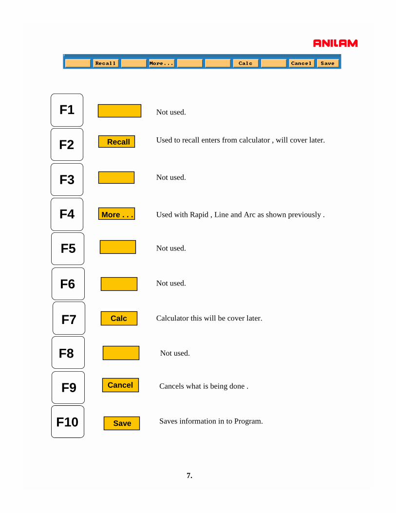
Not used.
Used to recall enters from calculator , will cover later.
Not used.
Used with Rapid , Line and Arc as shown previously .
Not used.
Not used.
Not used.
Calculator this will be cover later.
Cancels what is being done .
Saves information in to Program.

3000M CNC ControlCanned cycles
1. Basic Rapid to Z start, Feed to Z depth, Rapid to Z return.
2. Pecking Rapid to Z start, Feed to peck, Rapid to Z start, Rapid to last peck, Repeat peck cycle to Z depth,Rapid to Z return.
3. Boring Rapid to Z start, Feed to Z depth, Dwell, Feed to Z start, Rapid to Z return.
4. Chip Break Rapid to Z start, Feed to first peck, Retract chip break Inc, Feed first peck minus peck decr,Retract chip break Inc, Repeat cycle until min peck is reached and continue to Z depth, Rapid to Z return.
5.Tapping Rapid to Z start, Feed to Z depth, Dwell, Reverse spindle, Feed to Z start, Rapid to Z return.
6. Pattern Drilling locations that can be defined into a symmetrical Pattern.
7. Bolt Hole Drilling locations that can be defined into a symmetrical Hole Pattern.
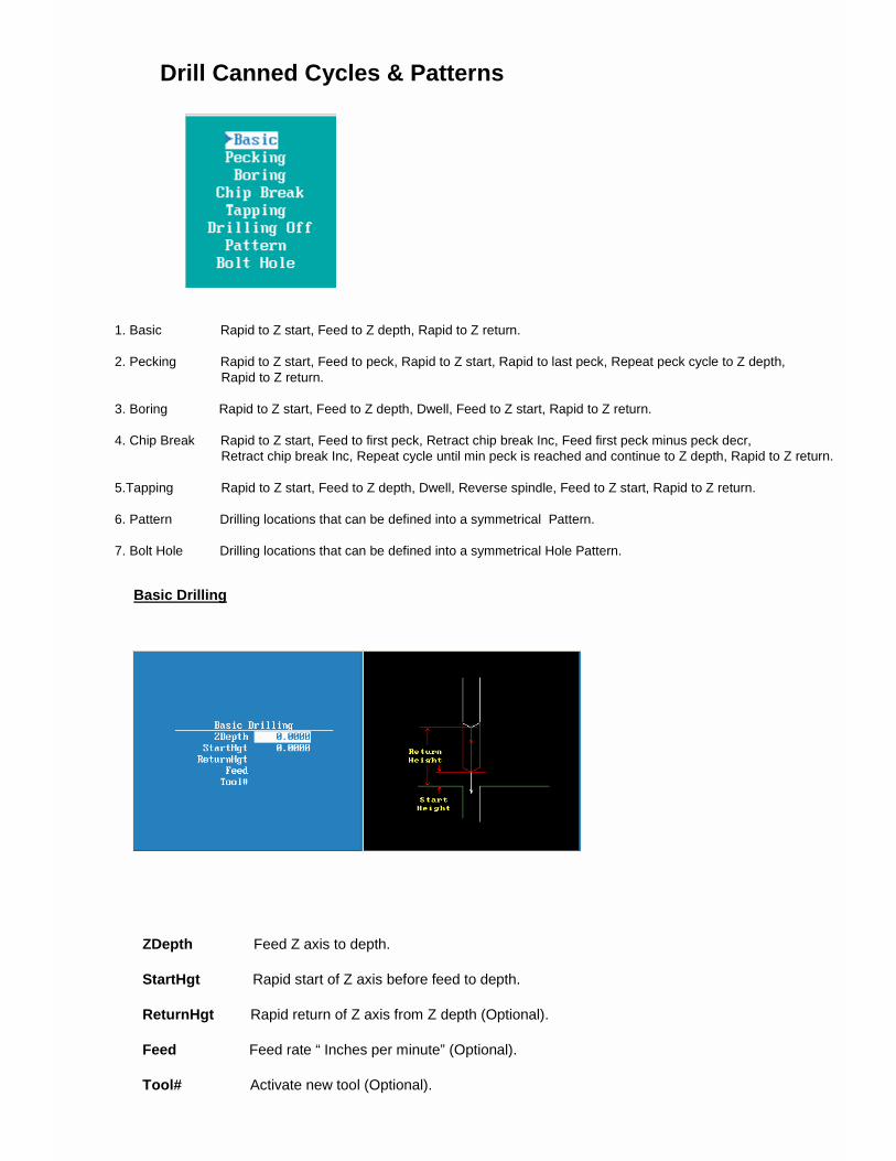
Drill Canned Cycles & Patterns
Basic Drilling
ZDepth Feed Z axis to depth.
StartHgt Rapid start of Z axis before feed to depth.
ReturnHgt Rapid return of Z axis from Z depth (Optional).
Feed Feed rate “ Inches per minute” (Optional).
Tool# Activate new tool (Optional).
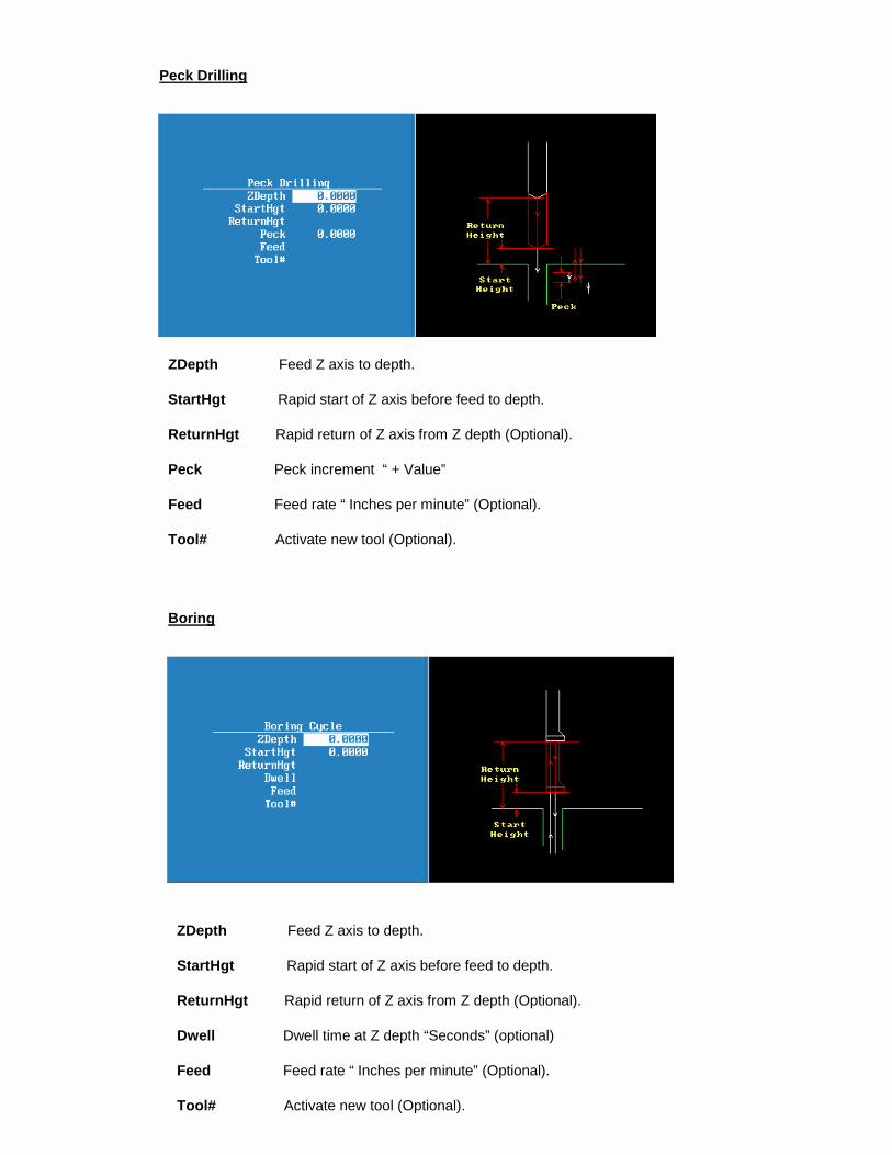
ZDepth Feed Z axis to depth.
StartHgt Rapid start of Z axis before feed to depth.
ReturnHgt Rapid return of Z axis from Z depth (Optional).
Peck Peck increment “ + Value”
Feed Feed rate “ Inches per minute” (Optional).
Tool# Activate new tool (Optional).
ZDepth Feed Z axis to depth.
StartHgt Rapid start of Z axis before feed to depth.
ReturnHgt Rapid return of Z axis from Z depth (Optional).
Dwell Dwell time at Z depth “Seconds” (optional)
Feed Feed rate “ Inches per minute” (Optional).
Tool# Activate new tool (Optional).
Peck Drilling
Boring
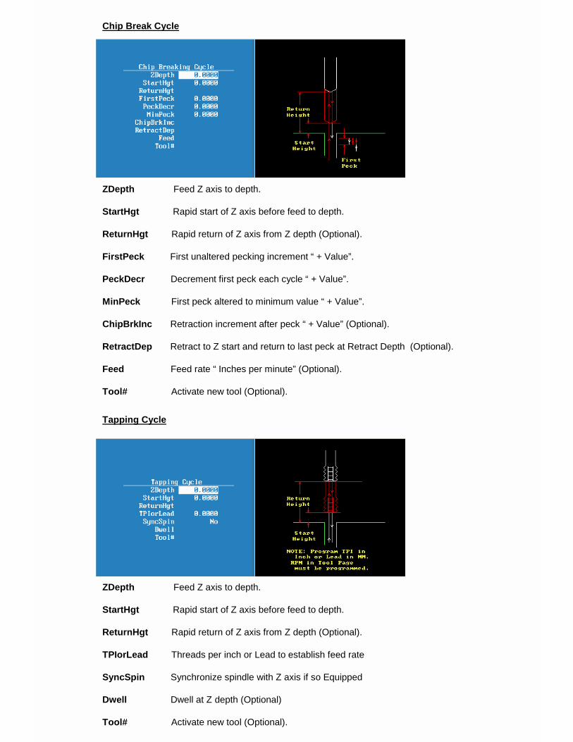
ZDepth Feed Z axis to depth.
StartHgt Rapid start of Z axis before feed to depth.
ReturnHgt Rapid return of Z axis from Z depth (Optional).
FirstPeck First unaltered pecking increment “ + Value”.
PeckDecr Decrement first peck each cycle “ + Value”.
MinPeck First peck altered to minimum value “ + Value”.
ChipBrkInc Retraction increment after peck “ + Value” (Optional).
RetractDep Retract to Z start and return to last peck at Retract Depth (Optional).
Feed Feed rate “ Inches per minute” (Optional).
Tool# Activate new tool (Optional).
Chip Break Cycle
Tapping Cycle
ZDepth Feed Z axis to depth.
StartHgt Rapid start of Z axis before feed to depth.
ReturnHgt Rapid return of Z axis from Z depth (Optional).
TPIorLead Threads per inch or Lead to establish feed rate
SyncSpin Synchronize spindle with Z axis if so Equipped
Dwell Dwell at Z depth (Optional)
Tool# Activate new tool (Optional).

Pattern Drill
Bolthole Drill
X X start location (Optional).
Y Y start location (Optional).
#XHoles Number of holes on X axis including starting hole.
#YHoles Number of holes on Y axis including starting hole.
XInc Incremental distance between all holes on X axis ”Use – or + values for direction”.
YInc Incremental distance between all holes on Y axis ”Use – or + values for direction”.
Angle Rotate entire pattern about X and Y starting hole (Optional).
XCenter X center of circle.
YCenter Y center of circle.
#Holes Number of holes in circle including starting hole.
Diameter Diameter of circle.
StartAngle First hole angle from 3 o’clock zero ( 0 to 360 degrees counter clockwise)or ( + counter clockwise degree increment / - clockwise degree increment).
EndAngle End hole angle from 3 o’clock zero ( 0 to 360 degrees counter clockwise) or( + CCW or – CW degree increment)_______________(EndAngle Optional).
IndexAngle Rotate entire pattern about circle center (Optional).

Thread Milling Cycle
WARNING: The first move in this cycle is a rapid move to the center of the thread before moving the Z-axis. Make sure the tool is properly located before calling up this cycle.
Thread Milling Cycle simplifies the programming required to mill a thread. Use the thread milling for cutting inside or outside threads. It will cut either Inch or MM, left or right hand, and Z movement up or down. A single tooth or multi-toothed tool may be used. Start can be at the top or bottom of the hole or boss. Tool Length Offset is set the same as with any other tool or operation. A tool diameter also has to be set in the tool table, as cutter compensation is built into this cycle (cutter compensation is not allowed during the use of this cycle). The tool must be positioned at center of hole or boss, or the parameters for XCenter and YCenter must be specified in the cycle.
XCenter, YCenter, ArcInRad, StockAmt, Passes, RoughFeed, FinFeed, and TaperAng are all optional Input; all other parameters must be programmed. If the feed rates are not programmed, the CNC will use last feed rate used. In a tapered thread the Major Diameter is always the major diameter of thread where the ZStart is set. Inside diameter is at finished depth and outside diameter is the diameter of boss.
To program a Thread Milling Cycle: 1. In Edit Mode, press Drill (F3) to display a pop-up menu. 2. Select Thread Mill from the pop-up menu, and press ENTER to
display the Thread Mill Graphic Menu. Refer to Figure 5-8.
Figure 5-8, Thread Mill Graphic Menu
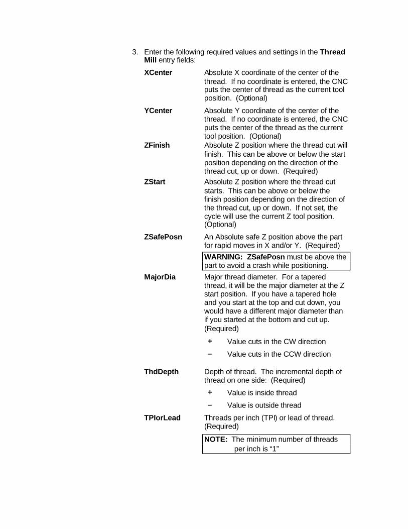
3. Enter the following required values and settings in the Thread Mill entry fields:
XCenter Absolute X coordinate of the center of the thread. If no coordinate is entered, the CNC puts the center of thread as the current tool position. (Optional)
YCenter Absolute Y coordinate of the center of the thread. If no coordinate is entered, the CNC puts the center of the thread as the current tool position. (Optional)
ZFinish Absolute Z position where the thread cut will finish. This can be above or below the start position depending on the direction of the thread cut, up or down. (Required)
ZStart Absolute Z position where the thread cut starts. This can be above or below the finish position depending on the direction of the thread cut, up or down. If not set, the cycle will use the current Z tool position. (Optional)
ZSafePosn An Absolute safe Z position above the part for rapid moves in X and/or Y. (Required) WARNING: ZSafePosn must be above the part to avoid a crash while positioning.
MajorDia Major thread diameter. For a tapered thread, it will be the major diameter at the Z start position. If you have a tapered hole and you start at the top and cut down, you would have a different major diameter than if you started at the bottom and cut up. (Required)
+ Value cuts in the CW direction – Value cuts in the CCW direction
ThdDepth Depth of thread. The incremental depth of thread on one side: (Required) + Value is inside thread – Value is outside thread
TPIorLead Threads per inch (TPI) or lead of thread. (Required)
NOTE: The minimum number of threads per inch is “1”

ArcInRad Size of radius arcing into start of thread. (Optional)
NOTE: If ArcInRad is a positive value or not set and the thread is “inside,” the cycle will always return to the center between passes. If ArcInRad is a negative value, the cutter will move to the start or end point that is closest to the center if inside thread, and farthest away from center if outside thread. If ArcInRad is not specified and the thread is “outside,” the cutter will back away from the largest diameter by an amount equal to the thread depth.
StockAmt Amount to leave for a finish pass after the roughing passes. (Optional)
Passes Number of roughing cuts to be taken. (Optional)
NOTE: If StockAmt is not set or set to zero and Passes is 1 or 0, the cycle will make just one pass at the full depth.. If StockAmt is set to greater than zero and Passes is 1 or 0, the cycle will make just one pass at the stock depth and one pass at full thread depth. If Passes is set to a negative number, all non-cutting positioning moves will be rapid.
RoughFeed Feedrate for roughing. (If not set, the cycle will use the current active feedrate.) (Optional)
FinFeed Feedrate for the finish pass. (If not set, the cycle will use the current active feedrate.) (Optional)
TaperAng Angle on one side of the thread (not the included angle). The angle is measured from the right side going counter clockwise with a positive number and clockwise with a negative number. A straight pipe tape with an inside cut would be -1.7833. If not set, then the thread is straight. (Optional)
If X and Y are not programmed, position tool center of the thread before calling the “Thread Mill” cycle:
• X and Y will rapid to the starting position of the thread.
• Z will rapid to the safe height specified in ZSafePosn.

• The Z axis will feed down to the start cut position ZStart. This could be above or below the Z position specified in the ZFinish position.
• Depending on what is in the ArcInRad parameter, the tool will arc into the first cut position.
• Spiral up or down, depending on the difference between ZFinish and ZStart and go counterclockwise or clockwise depending if MajorDia is plus or minus.
• Then arc-out and feed to the thread center for inside threads, or a safe distance away from the thread for outside threads depending on the value in ArcInRad.
• Then feed back to the ZStart height.
• Then feed X and Y to the next depth of cut. The depth of each roughing pass will be the thread depth specified in the ThdDepth parameter minus the stock amount specified in the StockAmt parameter, divided by the number of roughing passes specified in the Passes parameter.
• The cycle repeats this process until the final finish pass.
• It will then cut the thread at the full thread major diameter.
When cutting a tapered on an inside thread, care should be taken. An error will be generated if the diameter on the small end of the taper becomes too small for the tool to fit along with arc in and out moves. Not entering an arc-in value in the ArcInRad parameter will allow the cycle to move to the center of the hole for maximum clearance.
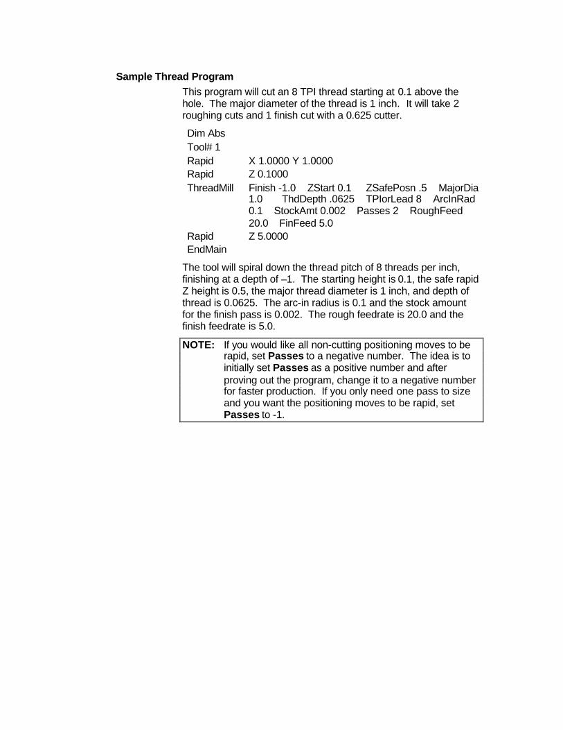
Sample Thread Program This program will cut an 8 TPI thread starting at 0.1 above the hole. The major diameter of the thread is 1 inch. It will take 2 roughing cuts and 1 finish cut with a 0.625 cutter.
Dim Abs Tool# 1 Rapid X 1.0000 Y 1.0000 Rapid Z 0.1000 ThreadMill Finish -1.0 ZStart 0.1 ZSafePosn .5 MajorDia
1.0 ThdDepth .0625 TPIorLead 8 ArcInRad 0.1 StockAmt 0.002 Passes 2 RoughFeed 20.0 FinFeed 5.0
Rapid Z 5.0000 EndMain
The tool will spiral down the thread pitch of 8 threads per inch, finishing at a depth of –1. The starting height is 0.1, the safe rapid Z height is 0.5, the major thread diameter is 1 inch, and depth of thread is 0.0625. The arc-in radius is 0.1 and the stock amount for the finish pass is 0.002. The rough feedrate is 20.0 and the finish feedrate is 5.0.
NOTE: If you would like all non-cutting positioning moves to be rapid, set Passes to a negative number. The idea is to initially set Passes as a positive number and after proving out the program, change it to a negative number for faster production. If you only need one pass to size and you want the positioning moves to be rapid, set Passes to -1.
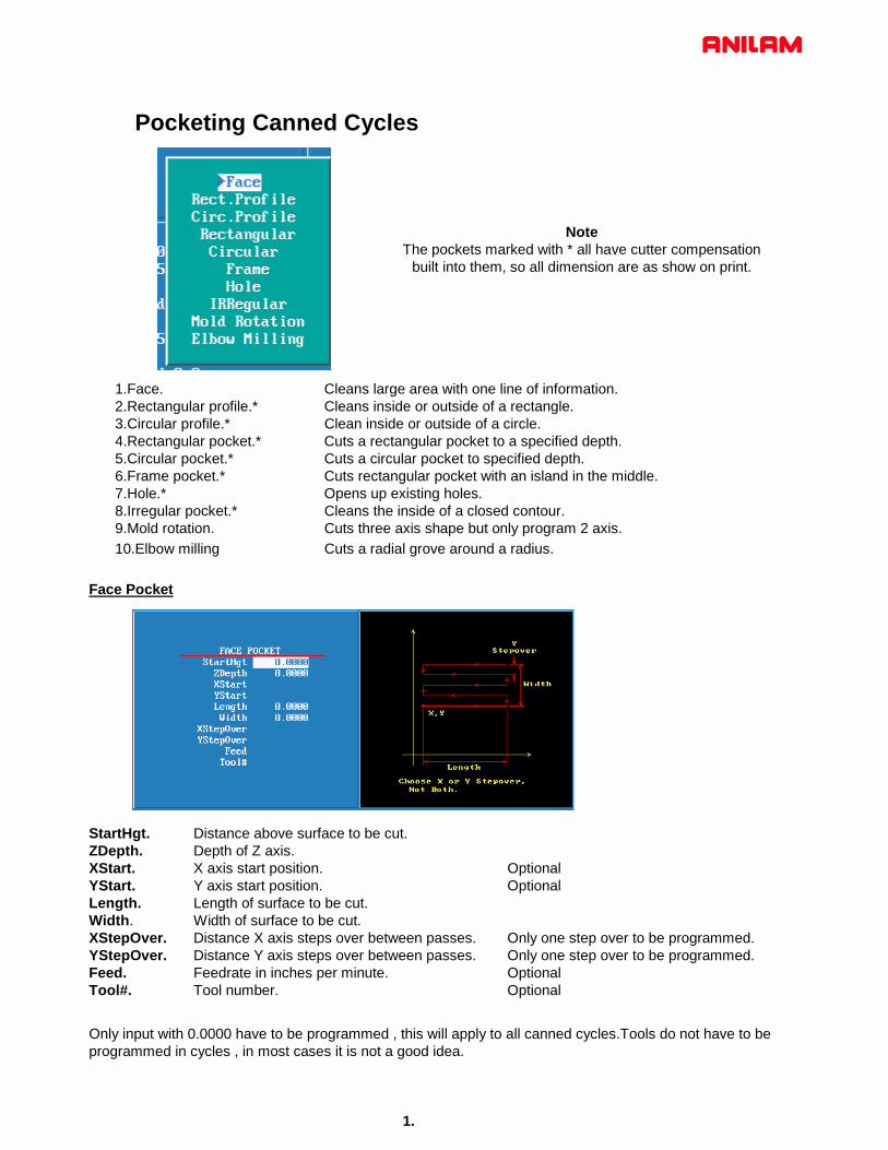
Pocketing Canned Cycles
1.Face. Cleans large area with one line of information.2.Rectangular profile.* Cleans inside or outside of a rectangle.3.Circular profile.* Clean inside or outside of a circle.4.Rectangular pocket.* Cuts a rectangular pocket to a specified depth.5.Circular pocket.* Cuts a circular pocket to specified depth.6.Frame pocket.* Cuts rectangular pocket with an island in the middle.7.Hole.* Opens up existing holes.8.Irregular pocket.* Cleans the inside of a closed contour.9.Mold rotation. Cuts three axis shape but only program 2 axis.10.Elbow milling Cuts a radial grove around a radius.
StartHgt. Distance above surface to be cut.ZDepth. Depth of Z axis.XStart. X axis start position. OptionalYStart. Y axis start position. OptionalLength. Length of surface to be cut.Width. Width of surface to be cut.XStepOver. Distance X axis steps over between passes. Only one step over to be programmed.YStepOver. Distance Y axis steps over between passes. Only one step over to be programmed.Feed. Feedrate in inches per minute. OptionalTool#. Tool number. Optional
1.
Face Pocket
Only input with 0.0000 have to be programmed , this will apply to all canned cycles.Tools do not have to be programmed in cycles , in most cases it is not a good idea.
NoteThe pockets marked with * all have cutter compensation
built into them, so all dimension are as show on print.
2.
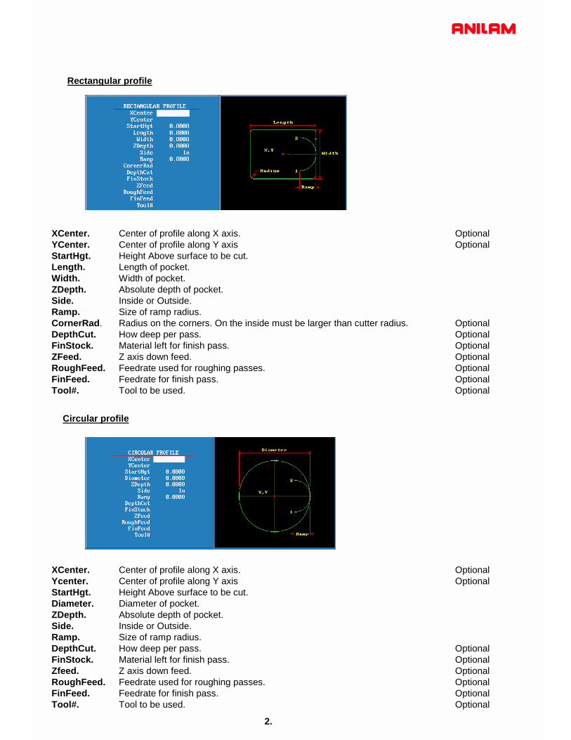
Rectangular profile
XCenter. Center of profile along X axis. OptionalYCenter. Center of profile along Y axis OptionalStartHgt. Height Above surface to be cut.Length. Length of pocket.Width. Width of pocket.ZDepth. Absolute depth of pocket.Side. Inside or Outside.Ramp. Size of ramp radius.CornerRad. Radius on the corners. On the inside must be larger than cutter radius. OptionalDepthCut. How deep per pass. OptionalFinStock. Material left for finish pass. OptionalZFeed. Z axis down feed. OptionalRoughFeed. Feedrate used for roughing passes. OptionalFinFeed. Feedrate for finish pass. OptionalTool#. Tool to be used. Optional
XCenter. Center of profile along X axis. OptionalYcenter. Center of profile along Y axis OptionalStartHgt. Height Above surface to be cut.Diameter. Diameter of pocket.ZDepth. Absolute depth of pocket.Side. Inside or Outside.Ramp. Size of ramp radius.DepthCut. How deep per pass. OptionalFinStock. Material left for finish pass. OptionalZfeed. Z axis down feed. OptionalRoughFeed. Feedrate used for roughing passes. OptionalFinFeed. Feedrate for finish pass. OptionalTool#. Tool to be used. Optional
Circular profile
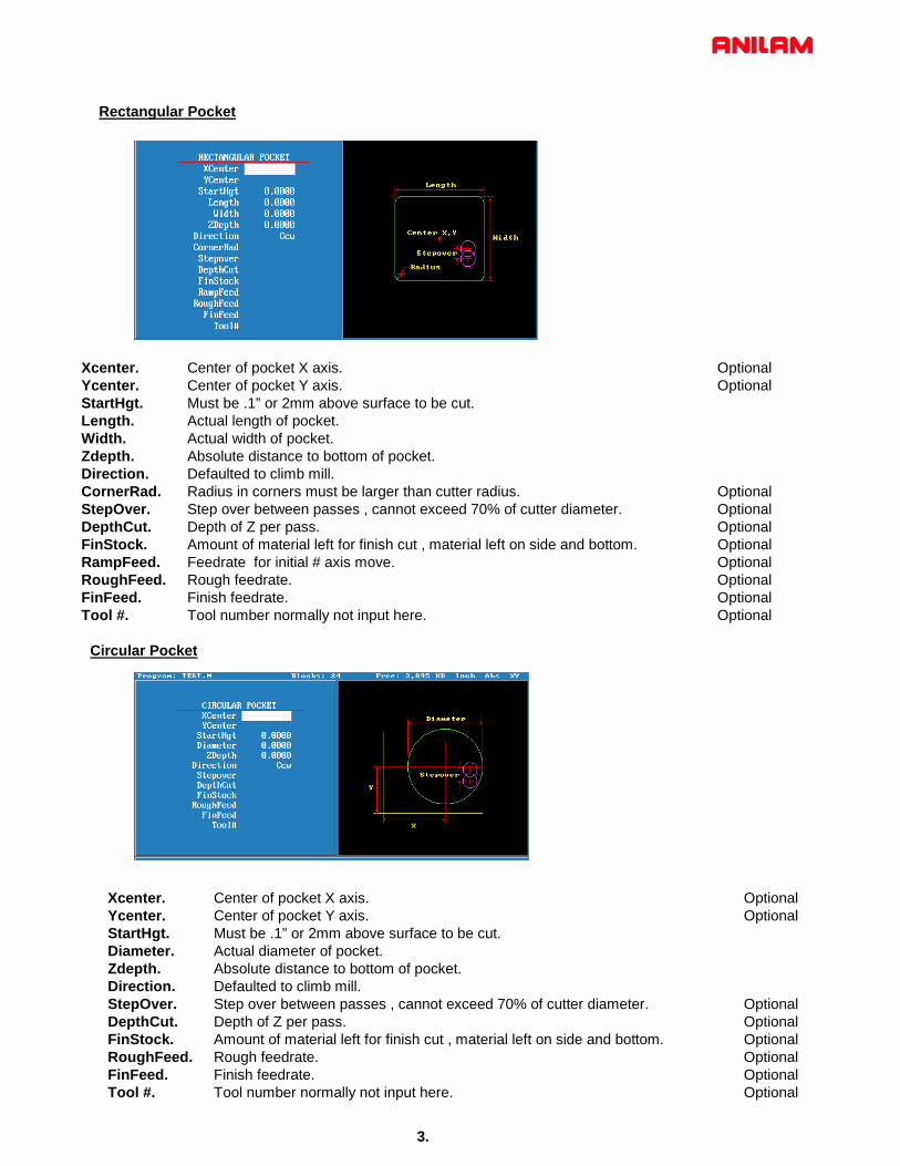
Rectangular Pocket
Xcenter. Center of pocket X axis. OptionalYcenter. Center of pocket Y axis. OptionalStartHgt. Must be .1” or 2mm above surface to be cut. Length. Actual length of pocket.Width. Actual width of pocket.Zdepth. Absolute distance to bottom of pocket. Direction. Defaulted to climb mill.CornerRad. Radius in corners must be larger than cutter radius. OptionalStepOver. Step over between passes , cannot exceed 70% of cutter diameter. OptionalDepthCut. Depth of Z per pass. OptionalFinStock. Amount of material left for finish cut , material left on side and bottom. OptionalRampFeed. Feedrate for initial # axis move. OptionalRoughFeed. Rough feedrate. OptionalFinFeed. Finish feedrate. OptionalTool #. Tool number normally not input here. Optional
Circular Pocket
Xcenter. Center of pocket X axis. OptionalYcenter. Center of pocket Y axis. OptionalStartHgt. Must be .1” or 2mm above surface to be cut. Diameter. Actual diameter of pocket.Zdepth. Absolute distance to bottom of pocket. Direction. Defaulted to climb mill.StepOver. Step over between passes , cannot exceed 70% of cutter diameter. OptionalDepthCut. Depth of Z per pass. OptionalFinStock. Amount of material left for finish cut , material left on side and bottom. OptionalRoughFeed. Rough feedrate. OptionalFinFeed. Finish feedrate. OptionalTool #. Tool number normally not input here. Optional
3.
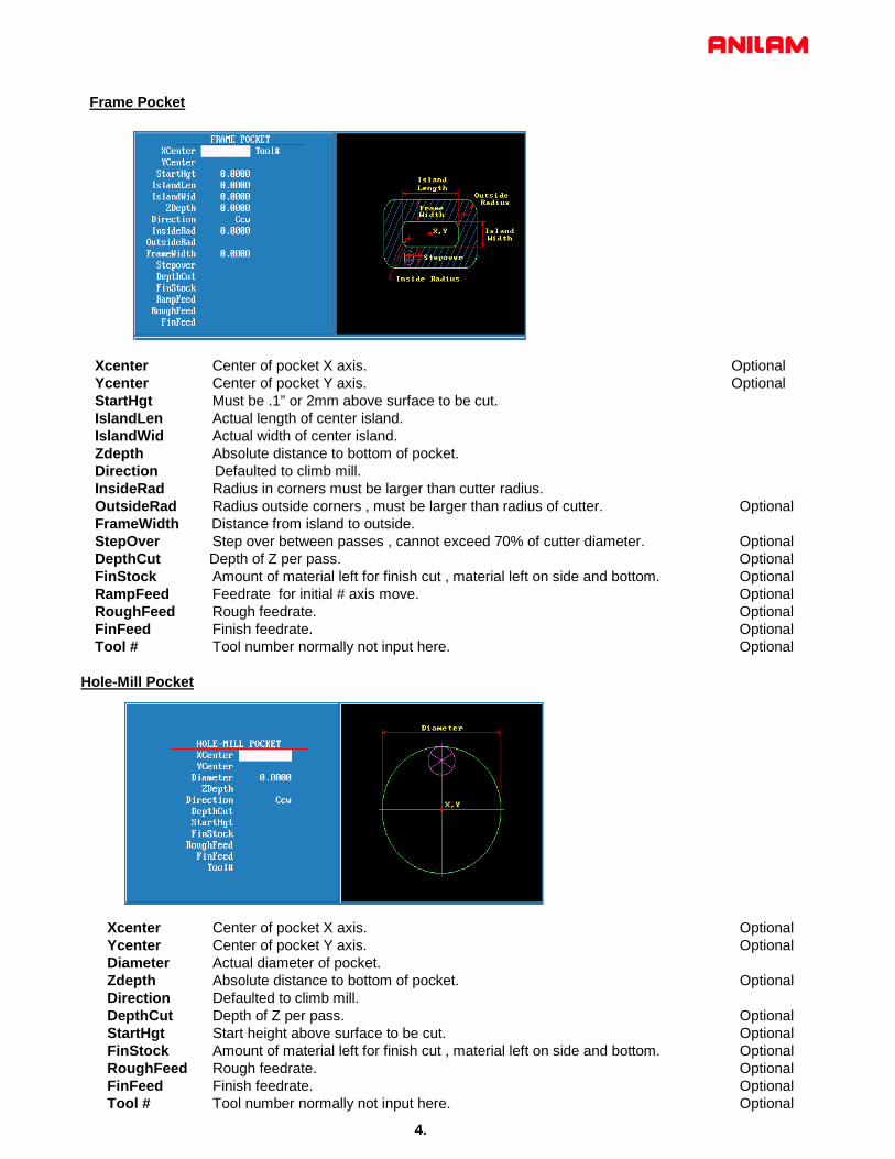
Frame Pocket
Xcenter Center of pocket X axis. OptionalYcenter Center of pocket Y axis. OptionalStartHgt Must be .1” or 2mm above surface to be cut. IslandLen Actual length of center island.IslandWid Actual width of center island.Zdepth Absolute distance to bottom of pocket. Direction Defaulted to climb mill.InsideRad Radius in corners must be larger than cutter radius.OutsideRad Radius outside corners , must be larger than radius of cutter. OptionalFrameWidth Distance from island to outside.StepOver Step over between passes , cannot exceed 70% of cutter diameter. OptionalDepthCut Depth of Z per pass. OptionalFinStock Amount of material left for finish cut , material left on side and bottom. OptionalRampFeed Feedrate for initial # axis move. OptionalRoughFeed Rough feedrate. OptionalFinFeed Finish feedrate. OptionalTool # Tool number normally not input here. Optional
Hole-Mill Pocket
Xcenter Center of pocket X axis. OptionalYcenter Center of pocket Y axis. OptionalDiameter Actual diameter of pocket.Zdepth Absolute distance to bottom of pocket. OptionalDirection Defaulted to climb mill.DepthCut Depth of Z per pass. OptionalStartHgt Start height above surface to be cut. OptionalFinStock Amount of material left for finish cut , material left on side and bottom. OptionalRoughFeed Rough feedrate. OptionalFinFeed Finish feedrate. OptionalTool # Tool number normally not input here. Optional
4.

5.
Irregular Pocket
Sub# # of profile subroutine.X Start position of profile X axis. OptionalY Start position of profile Y axis. OptionalStartHgt Start height .1” or 2mm above surface to be cut.Zdepth Z depth of pocket absolute.Angle Angle of first cut. OptionalXstart Position of X axis before moving to start of profile. OptionalYstart Position of Y axis before moving to start of profile. OptionalStepover Distance cut will move over between passes.DepthCut Depth of cut per pass. OptionalFinStock Amount of material left for finish pass. Leave stock on Optional
side and bottom of pocket.RampFeed Feedrate into material.Normally Z axis into material. OptionalRoughFeed Feedrate for roughing passes. OptionalFinFeed Feedrate for finish pass OptionalTool# Tool # Optional
Note
A subroutine has to be programmed for this cycle . The subroutine must start and end at the same coordinates. The first move can be a Rapid , put both X and Y axis in this blockalso the last block should have both X and Y axis coordinates.
Angle would normally only be used when starting point of profile is on a radius.
6.
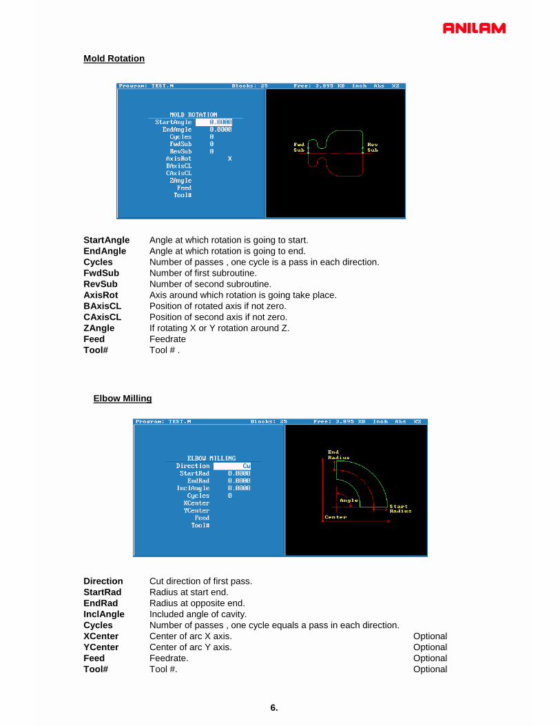
Mold Rotation
StartAngle Angle at which rotation is going to start.EndAngle Angle at which rotation is going to end.Cycles Number of passes , one cycle is a pass in each direction.FwdSub Number of first subroutine.RevSub Number of second subroutine.AxisRot Axis around which rotation is going take place.BAxisCL Position of rotated axis if not zero.CAxisCL Position of second axis if not zero.ZAngle If rotating X or Y rotation around Z.Feed Feedrate Tool# Tool # .
Elbow Milling
Direction Cut direction of first pass.StartRad Radius at start end.EndRad Radius at opposite end.InclAngle Included angle of cavity.Cycles Number of passes , one cycle equals a pass in each direction.XCenter Center of arc X axis. OptionalYCenter Center of arc Y axis. OptionalFeed Feedrate. OptionalTool# Tool #. Optional

Pockets with Islands
This cycle allows islands in irregular pockets. The main pocket must the lowest subroutine number. Normally, this would be one (1). Pockets with Islands can be programmed using: • DXF (see “Section 15, Using DXF for Pockets with Islands
(G162)”) • Subroutines
More than one Island cycle can be programmed at a time. They may be strung together, but on separate lines. Islands can be programmed inside of islands. Five islands can be put on a line. The shape number subroutine number is used as inputs.
Using Subroutines for Pockets with Islands This example using subroutinges for Pockets with Islands uses the following illustration. See Figure 5-24 and Table 5-1 Pockets with Islands Subroutines Programming Example.
The numbers are the subroutine numbers.
X
YMain pocket #1
Outside of island #4
Inside of island #6
Island #2
Island #3
Island #5
ISLANDSUB
Figure 5-24, Subroutines Pockets with Islands Example Workpiece
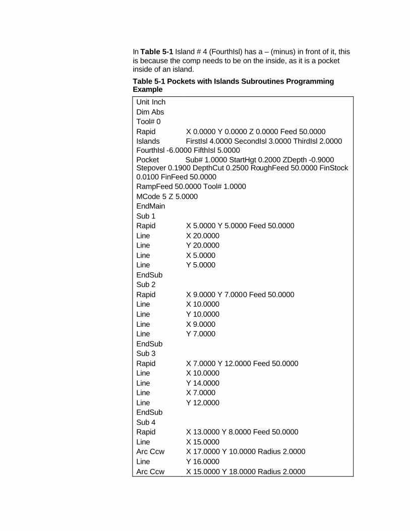
In Table 5-1 Island # 4 (FourthIsl) has a – (minus) in front of it, this is because the comp needs to be on the inside, as it is a pocket inside of an island. Table 5-1 Pockets with Islands Subroutines Programming Example Unit Inch Dim Abs Tool# 0 Rapid X 0.0000 Y 0.0000 Z 0.0000 Feed 50.0000 Islands FirstIsl 4.0000 SecondIsl 3.0000 ThirdIsl 2.0000 FourthIsl -6.0000 FifthIsl 5.0000 Pocket Sub# 1.0000 StartHgt 0.2000 ZDepth -0.9000 Stepover 0.1900 DepthCut 0.2500 RoughFeed 50.0000 FinStock 0.0100 FinFeed 50.0000 RampFeed 50.0000 Tool# 1.0000 MCode 5 Z 5.0000 EndMain Sub 1 Rapid X 5.0000 Y 5.0000 Feed 50.0000 Line X 20.0000 Line Y 20.0000 Line X 5.0000 Line Y 5.0000 EndSub Sub 2 Rapid X 9.0000 Y 7.0000 Feed 50.0000 Line X 10.0000 Line Y 10.0000 Line X 9.0000 Line Y 7.0000 EndSub Sub 3 Rapid X 7.0000 Y 12.0000 Feed 50.0000 Line X 10.0000 Line Y 14.0000 Line X 7.0000 Line Y 12.0000 EndSub Sub 4 Rapid X 13.0000 Y 8.0000 Feed 50.0000 Line X 15.0000 Arc Ccw X 17.0000 Y 10.0000 Radius 2.0000 Line Y 16.0000 Arc Ccw X 15.0000 Y 18.0000 Radius 2.0000
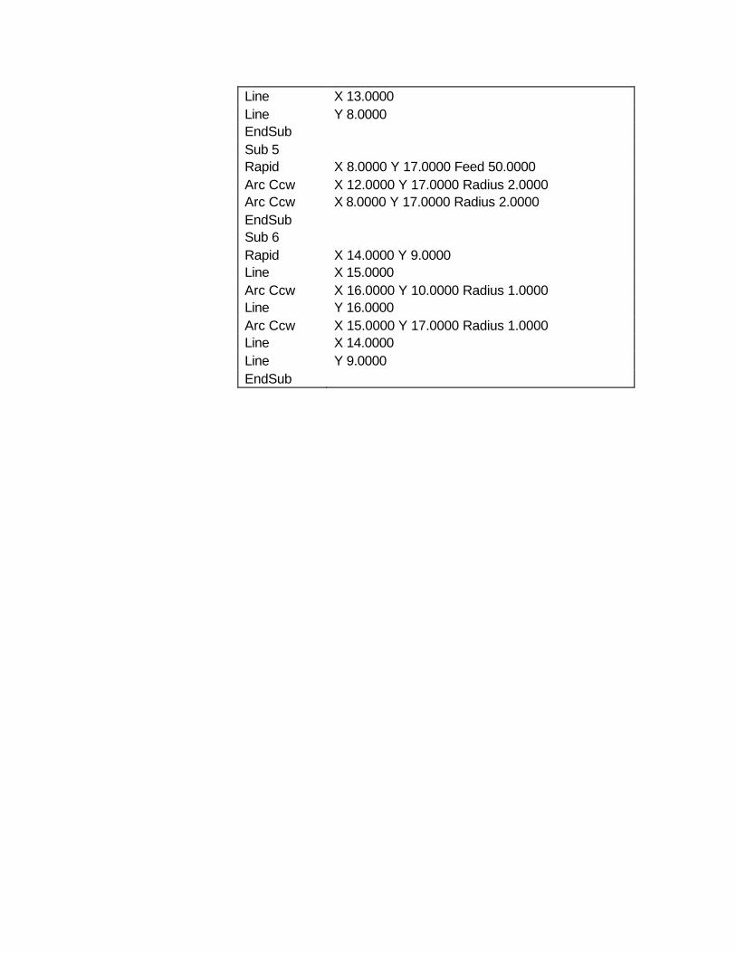
Line X 13.0000 Line Y 8.0000 EndSub Sub 5 Rapid X 8.0000 Y 17.0000 Feed 50.0000 Arc Ccw X 12.0000 Y 17.0000 Radius 2.0000 Arc Ccw X 8.0000 Y 17.0000 Radius 2.0000 EndSub Sub 6 Rapid X 14.0000 Y 9.0000 Line X 15.0000 Arc Ccw X 16.0000 Y 10.0000 Radius 1.0000 Line Y 16.0000 Arc Ccw X 15.0000 Y 17.0000 Radius 1.0000 Line X 14.0000 Line Y 9.0000 EndSub

7.
There are two more canned cycles , to get to these press soft key.Mill
Soft key will change as above press a pop-up will appear as below.More
F5
F7
Ellipse and spiral both must be programmed incrementally .
Put height light on Ellipse press screen will change as below.
ENTER

8.
Direction Direction of cut CW or CCW.X Distance from Start to End X axis of Ellipse. Y Distance from Start to End Y axis of Ellipse.Z Distance from Start to End Z axis of Ellipse.Xcenter Distance from Start to Center X axis of Ellipse.Ycenter Distance from Start to Center Y axis of Ellipse.HalfLength Half the length of Ellipse X axis.HalfWidth Half the width of Ellipse Y axis.Feed Feedrate.CompSide Tool compensation none , inside or outside.Tool# Tool number.
If plane is changed to XZ plane Ycenter would change to ZCenter and half width is Z axis .If plane is changed to YZ plane Xcenter would change to YCenter and half length would be Y axis .Using in side or outside tool compensation the the cutter must be placed in the correct compensatedposition , before programming Ellipse. All dimension MUST be Incremental when programming this cycle.

9.
Direction Direction of Spiral Clockwise or Counter Clockwise.X Distance from Start to End X axis . Y Distance from Start to End Y axis .Z Distance from Start to End Z axis.Xcenter Distance from Start to Center X.Ycenter Distance from Start to Center Y.Revs Number of Revolutions.Feed Feedrate.Tool# Tool number.
This can be programmed in XY , XZ or YZ planes , the center designations withchange accord selected plane .All dimension MUST be Incremental when programming this cycleCutter compensation no allowed with this cycle.If cutting a thread using this cycle the distance moved in Z into numberof revolutions will equal lead of thread .

Engraving, Repeat, and Mill Cycles This section describes operation of three new cycles:
q Engraving Cycle q Repeat Cycle q Mill Cycle
Engraving Cycle The Engraving cycle provides a quick and easy way to engrave part numbers, legends, or any alpha/numeric inscription. The usual type of cutter is a sharp point or center-drill type tool. Options are given for engraving on an angle and mirror is supported for engraving molds. When executed, the CNC rapids to the start point, then to the StartHgt. It then feeds to the Zdepth specified and begins cutting the Text selected.
Programming the Engraving Cycle To program the Engraving Cycle: 1. In Edit mode, press Mill (F5) and More (F7) to display the
More pop-up menu, Figure 5-48. Highlight Engrave and press ENTER to display the Engraving Cycle screen, Figure 5-49, Engraving Cycle Screen.
2. Complete the entry fields (refer to Table 5-2, Engraving Cycle Entry Fields), and press ENTER.
Figure 5-48, More Pop-up Menu
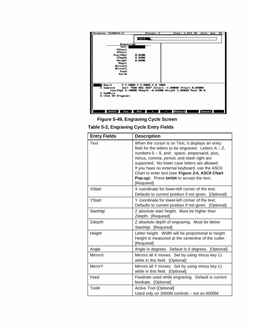
Figure 5-49, Engraving Cycle Screen
Table 5-2, Engraving Cycle Entry Fields
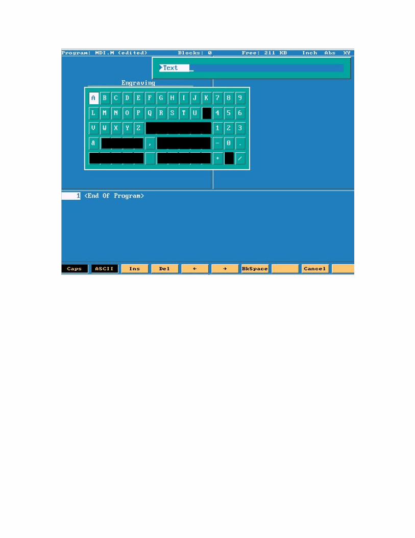
Entry Fields Description Text When the cursor is on Text, it displays an entry
field for the letters to be engraved. Letters A – Z, numbers 0 – 9, and: space, ampersand, plus, minus, comma, period, and slash right are supported. No lower case letters are allowed. If you have no external keyboard, use the ASCII Chart to enter text (see Figure 2-4, ASCII Chart Pop-up). Press ENTER to accept the text. [Required]
XStart X coordinate for lower-left corner of the text. Defaults to current position if not given. [Optional]
YStart Y coordinate for lower-left corner of the text. Defaults to current position if not given. [Optional]
StartHgt Z absolute start height. Must be higher than Zdepth. [Required]
Zdepth Z absolute depth of engraving. Must be below StartHgt. [Required]
Height Letter height. Width will be proportional to height. Height is measured at the centerline of the cutter. [Required]
Angle Angle in degrees. Default is 0 degrees. [Optional] MirrorX Mirrors all X moves. Set by using minus key (-)
while in this field. [Optional] MirrorY Mirrors all Y moves. Set by using minus key (-)
while in this field. [Optional] Feed Feedrate used while engraving. Default is current
feedrate. [Optional] Tool# Active Tool [Optional]
Used only on 3000M controls – not on 6000M
Sample Engraving Cycle Program 1 Dim Abs 2 Unit Inch 3 Rapid X 0.00000 Y 0.00000 4 Tool# 1 5 Rapid X 1.00000 Y 1.00000 6 Rapid Z 0.10000 7 Engrave Text "ABCD" StartHgt 0.0100 ZDepth -0.0100 Height 0.5000 8 Rapid Z 1.00000 9 Rapid X 0.00000 Y 0.00000 10 EndMain
This program will rapid to X1.0 Y1.0. Z will rapid to 0.1 and the letters ABCD will be engraved 0.0100” deep and 0.500” high.
Repeat Cycle
The Repeat cycle allows a series of previously programmed blocks to be repeated. Some examples are going over the same contour while lowering the Z-axis, or drilling over a series of holes with a different drill cycle, or moving an operation to a different location using fixture offsets. Wherever it is used, the repeated blocks will be processed, just as if they were written in the program at that point.
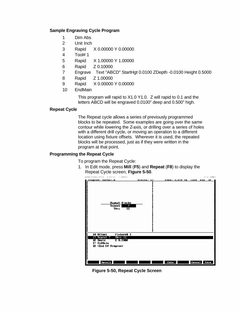
Programming the Repeat Cycle To program the Repeat Cycle: 1. In Edit mode, press Mill (F5) and Repeat (F8) to display the
Repeat Cycle screen, Figure 5-50.
Figure 5-50, Repeat Cycle Screen

2. Complete the entry fields (refer to Table 5-3), and press ENTER.
Table 5-3, Repeat Cycle Entry Fields
Entry Field Description
Repeat Type the block number you want to begin repeating. [Required]
Thru Type the block number you want to end the repeat. [Required]
3. When using a Modal Drilling Cycle with the Repeat feature, a DrillOff or non-move command must be included as the final block. For example, see “Sample Repeat Cycle Program” block 7–12 and block 15.
Sample Repeat Cycle Program 1 Dim Abs 2 Unit Inch 3 Offset Fixture# 0 4 Rapid X 0.0000 Y 0.0000 5 Tool# 1 6 Rapid Z 0.1000 7 BasicDrill ZDepth –0.50000 StartHgt 0.10000 Feed 15.0 8 Rapid X 1.00000 9 Y 1.0000 10 X 0.0000 11 Y 0.0000 12 DrillOff 13 Offset Fixture# 1 X 3.0000 Y 0.0000 14 Offset Fixture# 1 15 Repeat 7 Thru 12 16 Rapid Z 0.5000 17 EndMain
This program will drill four holes. A Fixture Offset is used to relocate X Y zero. When the Repeat Cycle is encountered, it will drill four more holes at the offset location.
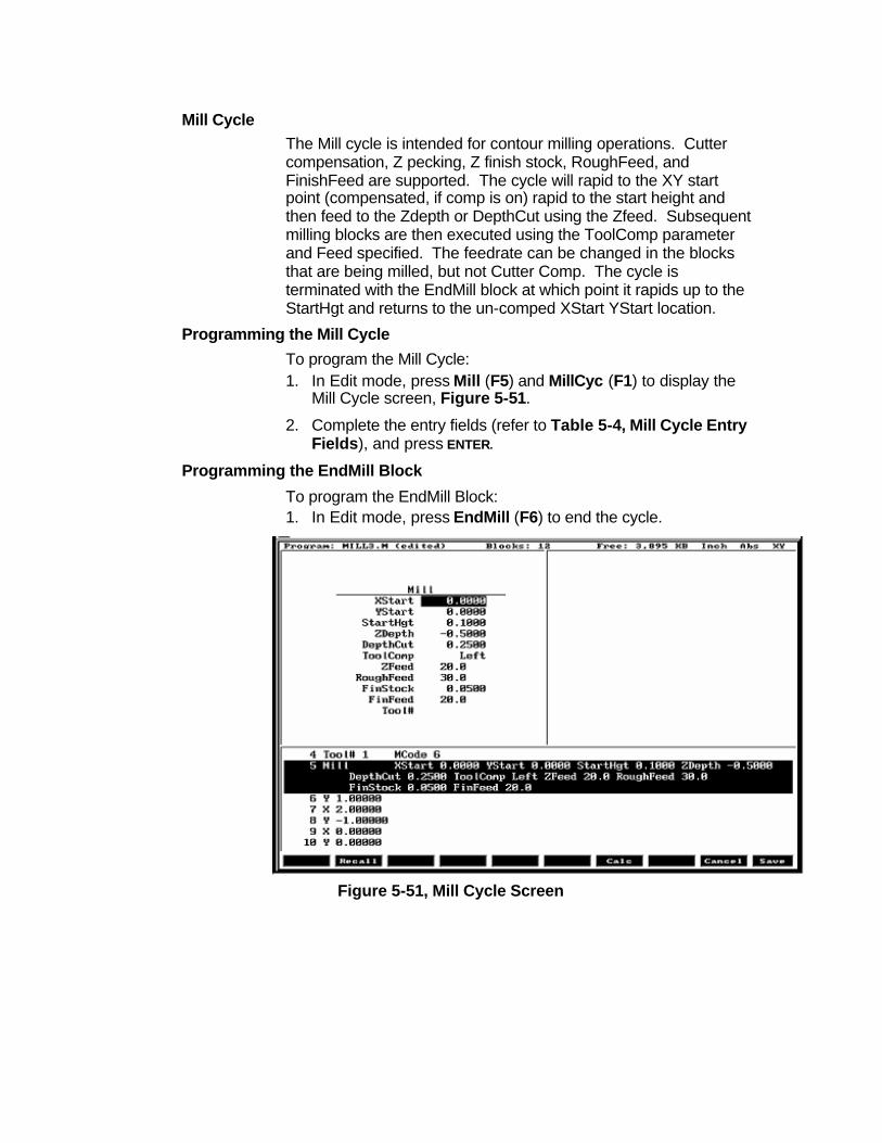
Mill Cycle The Mill cycle is intended for contour milling operations. Cutter compensation, Z pecking, Z finish stock, RoughFeed, and FinishFeed are supported. The cycle will rapid to the XY start point (compensated, if comp is on) rapid to the start height and then feed to the Zdepth or DepthCut using the Zfeed. Subsequent milling blocks are then executed using the ToolComp parameter and Feed specified. The feedrate can be changed in the blocks that are being milled, but not Cutter Comp. The cycle is terminated with the EndMill block at which point it rapids up to the StartHgt and returns to the un-comped XStart YStart location.
Programming the Mill Cycle To program the Mill Cycle: 1. In Edit mode, press Mill (F5) and MillCyc (F1) to display the
Mill Cycle screen, Figure 5-51.
2. Complete the entry fields (refer to Table 5-4, Mill Cycle Entry Fields), and press ENTER.
Programming the EndMill Block To program the EndMill Block: 1. In Edit mode, press EndMill (F6) to end the cycle.
Figure 5-51, Mill Cycle Screen

Table 5-4, Mill Cycle Entry Fields
Entry Field Description XStart X coordinate for start of Mill cycle. Defaults to
current position if not given. [Optional] YStart Y coordinate for start of Mill cycle. Defaults to
current position if not given. [Optional] StartHgt Z absolute start height. Must be 0.100” above work
surface (0.2mm). [Required] ZDepth Absolute depth of finished contour. [Required] DepthCut Depth of cut taken in a single pass. Cuts will be
adjusted so that all are equal pecks. [Optional] ToolComp Tool radius compensation Left or Right of
programmed path. Set by using minus key (-) while in this field. [Optional]
ZFeed Feedrate for Z-axis. Defaults to current feedrate. [Optional]
RoughFeed Feedrate for X and Y-axis. Defaults to current feedrate. [Optional]
FinStock Amount of stock to take for last Z peck. [Optional] FinFeed Feedrate used for FinStock. [Optional] Tool # Active Tool. [Optional]
Used only on 3000M controls – not on 6000M
Sample Mill Cycle Program 1 Dim Abs 2 Unit Inch 3 Rapid X 0.00000 Y 0.00000 4 Tool# 1 MCode 6 5 Mill XStart 0.00000 YStart 0.00000 StartHgt 0.10000
ZDepth -0.50000 DepthCut 0.25000 ToolComp Left ZFeed 20.0 Feed 30.0
6 Y 1.00000 7 X 2.00000 8 Y -1.00000 9 X 0.00000 10 Y 0.00000 11 EndMill 12 EndMain
This program will contour a square, in two Z pecks of 0.250” each. The blocks 6 thru 10 are the contour moves that will be comped to the left of tool path direction. Block 11, EndMill is required to show the end of the contour. The cutter will be returned to the start point, X0 Y0 at the start height of 0.100”.

3000M Rotate / Mirror / Scale

To get to RMS , when in edit press
Press F6 RMS
F8 Sub
Sub# Number of subroutine to Rotated, Mirrored or Scaled#Loops Number of time to repeat Rotation.
StartAngle Start angle of rotation.Angle Angle between Rotations.
Xcenter Center of Rotation X axis.Ycenter Center of Rotation Y axis.
Zcenter Center of Rotation Z axis.MirrorX Mirror X axis.MirrorY Mirror Y axis.MirrorZ Mirroe z axis.
Xscale Scale X axis.Yscale Scale Y axis.Zscale Scale Z axis.Tool# Tool number.
1.
2.
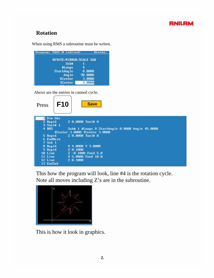
When using RMS a subroutine must be writen.
Rotation
Above are the entries in canned cycle.
F10 SavePress
This how the program will look, line #4 is the rotation cycle.Note all moves including Z’s are in the subroutine.
This is how it look in graphics.

3.
In the case only one rotation is required the entry would be as below.Note only 4 entries Sub , StartAngle , X & Y centers.
Program line would look as below.
Graphics of the single rotation appears below.
4.
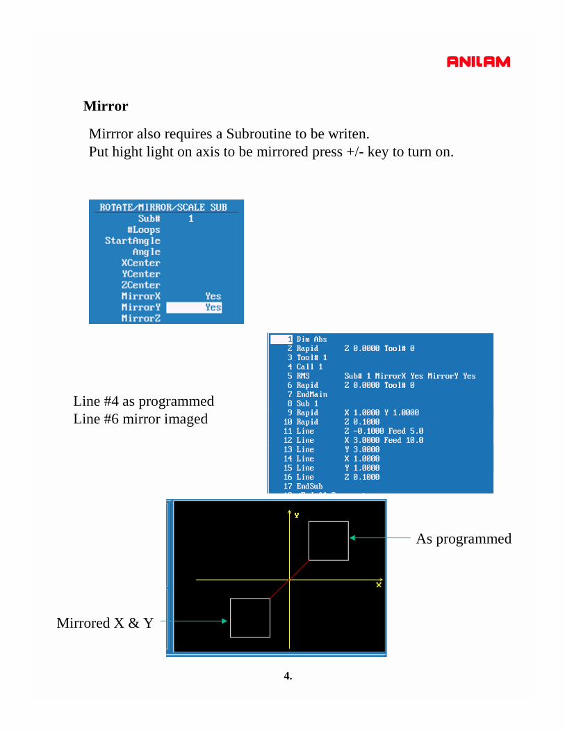
Mirror
Mirrror also requires a Subroutine to be writen.Put hight light on axis to be mirrored press +/- key to turn on.
As programmed
Mirrored X & Y
Line #4 as programmedLine #6 mirror imaged
5.
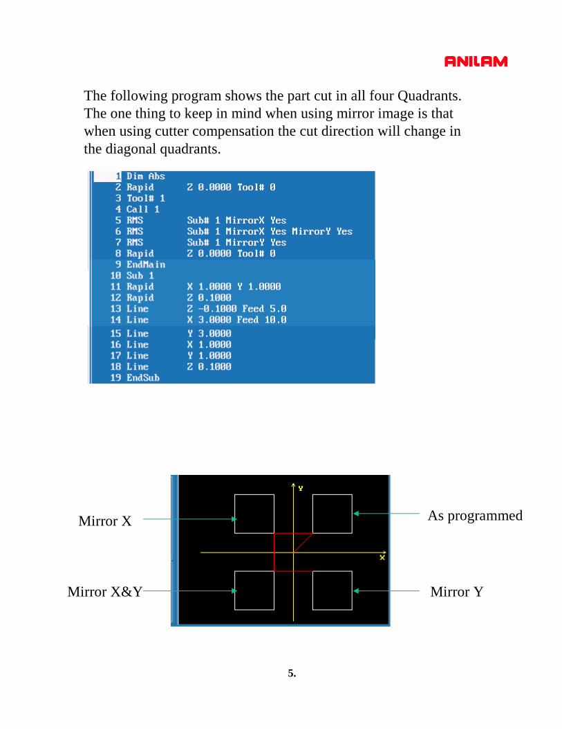
The following program shows the part cut in all four Quadrants.The one thing to keep in mind when using mirror image is thatwhen using cutter compensation the cut direction will change inthe diagonal quadrants.
As programmedMirror X
Mirror X&Y Mirror Y

6.
ScaleScale allow programmer to change the size of the part.One thing to remember is that if radii are involved bothaxis must be scale the same amount.
Line #5 original line #6 scaled x2
Scaled x2
Original size

7.

8.

3000M Cut / Copy / Paste
1.
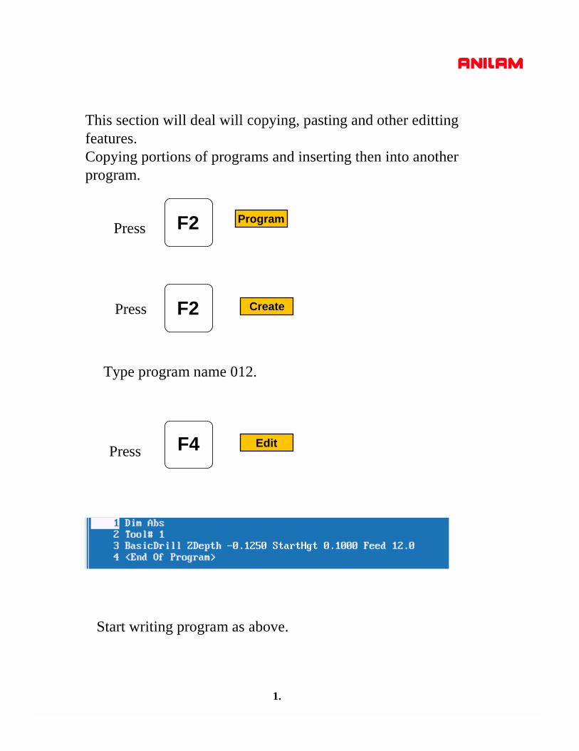
This section will deal will copying, pasting and other edittingfeatures.Copying portions of programs and inserting then into anotherprogram.
F2 ProgramPress
CreateF2Press
Type program name 012.
F4 EditPress
Start writing program as above.

2.
Softkeys will appear as above press F9 Misc
More….F1Press
Press
This pop-up window will come upcurser down to Open Program.
ENTER
Enter name of program number (0123)
that you need to copy from press ENTER

3.
F9 Misc More….F1Press
New program will now be on screen.
Press
Press on mark.ENTER
Put high light on first block be to be copied. Press ENTER
Use arrow keys to mark all blocks required.
4.
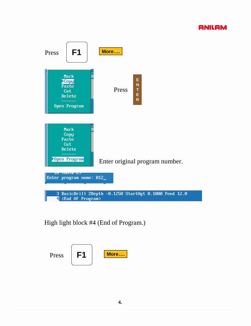
More….F1Press
Press ENTER
Enter original program number.
High light block #4 (End of Program.)
More….F1Press

5.
High light Paste pressENTER
It inserted lines 4 - 8 into proggram #012.
Cut is used remove a section of program once it’s marked.
Delete will cut pieces of marked program out.
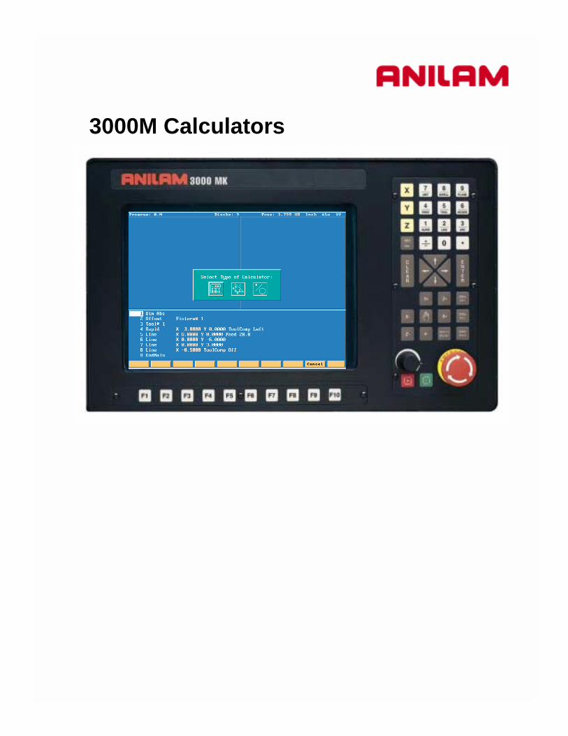
3000M Calculators

1.
To get to calculator Press F4 Edit
F7 CalcPress
Box will appear as below.
1.Pocket.2. Rightangled triangle.3. Geometery
The box with the hight light around it is the active one. In this caseit is the left hand box.

2.
ENTER
Press screen will appear as below.
Plus Minus Multiply Divide Brackets Functions Clear Store Exit

3.
When is press the listed functions are available.F7 Func
These funtions allow you to do trig and math problems.

4.
Hight light center icon , this is rightangled triangle calculator.
ENTER
Press screen will appear as below.
Enter any 2 sides or a side and an angle press all of the blanks will be filled in , the calculateddimensions will have an asterisk behind them.They can be stored and recalled later into a program.
F7 Find
5.
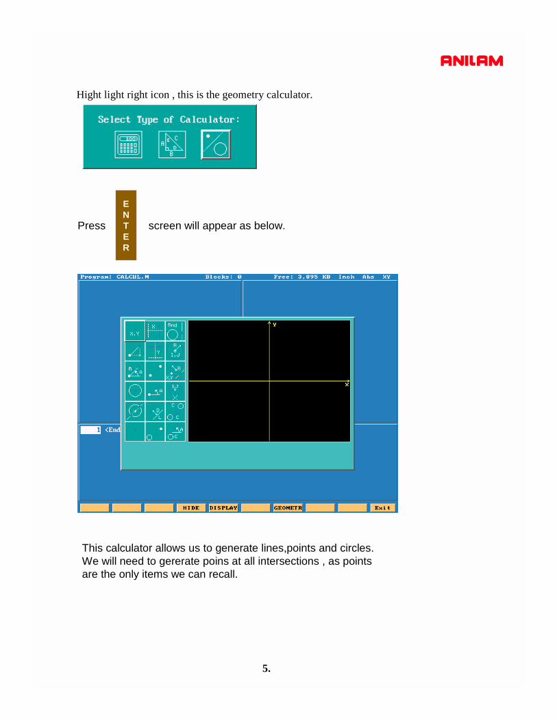
ENTER
Press screen will appear as below.
Hight light right icon , this is the geometry calculator.
This calculator allows us to generate lines,points and circles.We will need to gererate poins at all intersections , as pointsare the only items we can recall.

6.
The soft keys will appear as below.
F4
F5
F7
F10
Allow you change from calculator to program mode.
GEOMETR
DISPLAY
HIDE
EXIT
See below
See below
Exit Geometry calculator.
Fit to screen.Zoom in to an area on the screen.Redraw at current size.Halfs the screen size.Doubles screen size.
Lists all geometry.Calculates distance between two points.Deletes an item, need to give item number.Deletes all geometry.

7.
Point defined by co-ordinates X and Y
Point at a position X & Y from a previously defined point
Point at a distance R and an angle A from a previously defined point
Point at the centre of a circle
Point at an INTERSECTION between 2 elements
Point previously defined
Point Definitions
Vertical Line at a distance X from datum
Horizontal Line at a distance Y from part centreline
Line passing through 2 points
Line passing through a point at an angle A
Line parallel to another line L at a distance D
Line tangent to a circle passing through a point
Line Definitions
Circle tangent to 2 geometry elements
Circle defined by a Centre I & K with a radius R
Circle passing through a point X & Y with a radius R
Circle tangent to a line with a centre X & Y
Line Tangent to 2 circles
Line tangent to a circle at an angle A
Arc Definitions

8.
From the drawing below we are going to get all points required to program anirregular pocket.
6.25”
3.75
R 4.00
R 2.00
R 1.8
X0 Y0

9.
The first element to find is the 4.00 circle
Press pressF4 Edit F7 Calc
The third icon is hight lighted press
ENTER
Press
ENTER

10.
When is pressed screen will ask for Radius value, in this case 4., zero’s not required.
ENTER
Press It will now ask for a center definition and top left icon is hight lighted.This is one to use in this case.
ENTER
ENTER
Press
11.
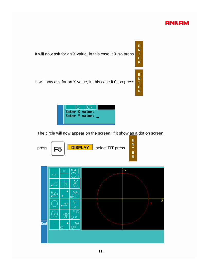
It will now ask for an X value, in this case it 0 ,so press
ENTER
It will now ask for an Y value, in this case it 0 ,so press
ENTER
The circle will now appear on the screen, if it show as a dot on screen
press select FIT pressF5 DISPLAY
ENTER
12.
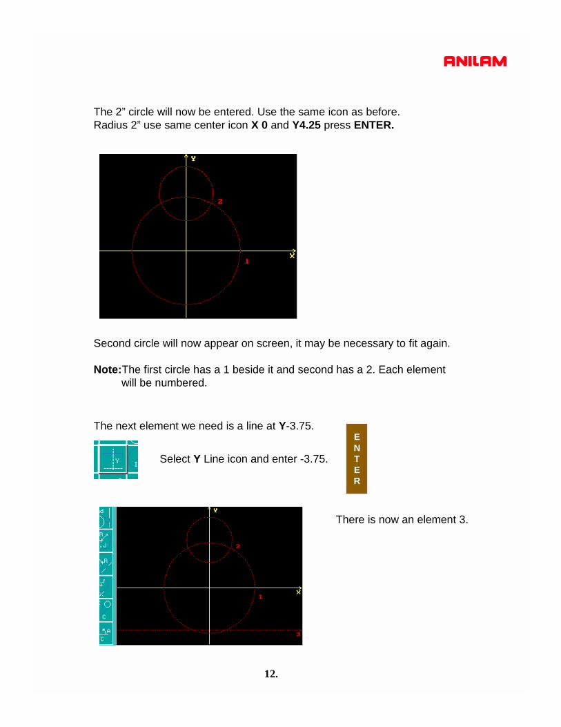
The 2” circle will now be entered. Use the same icon as before.Radius 2” use same center icon X 0 and Y4.25 press ENTER.
Second circle will now appear on screen, it may be necessary to fit again.
Note:The first circle has a 1 beside it and second has a 2. Each element will be numbered.
The next element we need is a line at Y-3.75.
Select Y Line icon and enter -3.75.
There is now an element 3.
ENTER
13.
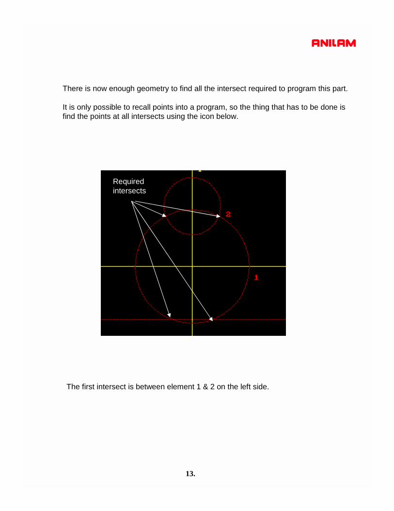
There is now enough geometry to find all the intersect required to program this part.
It is only possible to recall points into a program, so the thing that has to be done isfind the points at all intersects using the icon below.
The first intersect is between element 1 & 2 on the left side.
Required intersects

14.
Select the icon with a line going through a circle.
ENTER
Press select first element #1 select second #2, as there are two intersects
there is a choice of 1 or 2 in this case the desired one is #1.
There is now an element #4 which is the intersect between #! And #2.

15.
Using same icon,find intersects between ! & 3, two places and 1 & 2 right side.
Above is completed geometry, with all intersections marked with a point.
16.
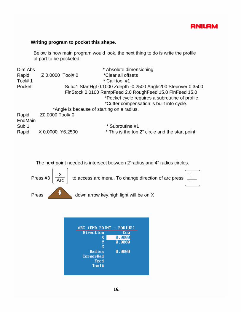
Writing program to pocket this shape.
Below is how main program would look, the next thing to do is write the profile of part to be pocketed.
Dim Abs * Absolute dimensioningRapid Z 0.0000 Tool# 0 *Clear all offsetsTool# 1 * Call tool #1Pocket Sub#1 StartHgt 0.1000 Zdepth -0.2500 Angle200 Stepover 0.3500
FinStock 0.0100 RampFeed 2.0 RoughFeed 15.0 FinFeed 15.0 *Pocket cycle requires a subroutine of profile.*Cutter compensation is built into cycle.
*Angle is because of starting on a radius.Rapid Z0.0000 Tool# 0EndMainSub 1 * Subroutine #1 Rapid X 0.0000 Y6.2500 * This is the top 2” circle and the start point.
The next point needed is intersect between 2”radius and 4” radius circles.
Press #3 to access arc menu. To change direction of arc press
Press down arrow key,high light will be on X
3Arc
17.
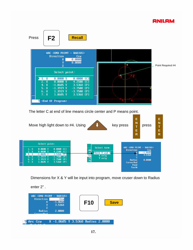
Press RecallF2
The letter C at end of line means circle center and P means point.
Move high light down to #4. Using key press press ENTER
ENTER
Dimensions for X & Y will be input into program, move cruser down to Radius
enter 2” .
SaveF10
Point Required #4
18.
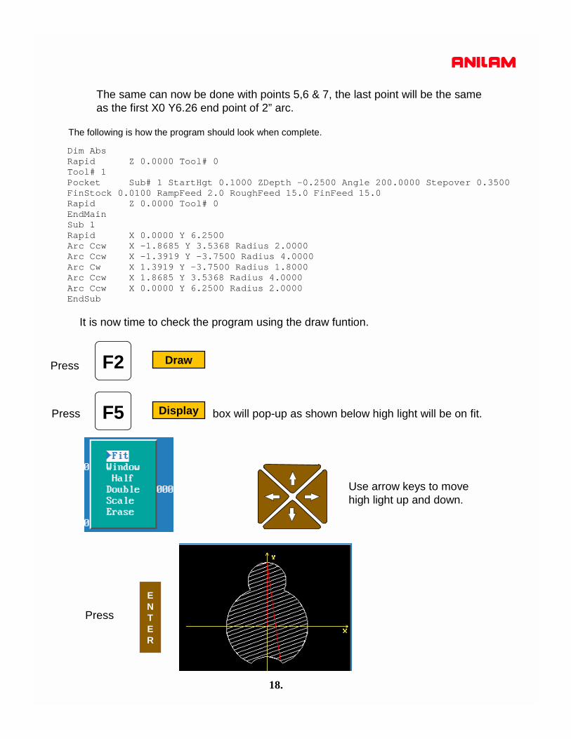
The same can now be done with points 5,6 & 7, the last point will be the same as the first X0 Y6.26 end point of 2” arc.
Dim AbsRapid Z 0.0000 Tool# 0Tool# 1Pocket Sub# 1 StartHgt 0.1000 ZDepth -0.2500 Angle 200.0000 Stepover 0.3500FinStock 0.0100 RampFeed 2.0 RoughFeed 15.0 FinFeed 15.0Rapid Z 0.0000 Tool# 0EndMainSub 1Rapid X 0.0000 Y 6.2500Arc Ccw X -1.8685 Y 3.5368 Radius 2.0000Arc Ccw X -1.3919 Y -3.7500 Radius 4.0000Arc Cw X 1.3919 Y -3.7500 Radius 1.8000Arc Ccw X 1.8685 Y 3.5368 Radius 4.0000Arc Ccw X 0.0000 Y 6.2500 Radius 2.0000EndSub
The following is how the program should look when complete.
It is now time to check the program using the draw funtion.
F5 DisplayPress box will pop-up as shown below high light will be on fit.
Press
ENTER
Use arrow keys to movehigh light up and down.
F2 DrawPress
19.
If all looks good in draw part is ready to cut.
ExitF10
ExitF10
Press
Press
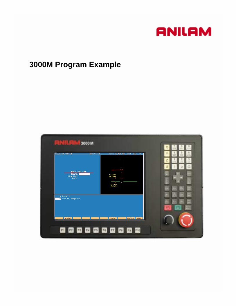
3000M Program Example

Typical starting program

1.
F1
F2
F6
F7
F8
F9
F10
Teach
F3 Drill
F4 Pocket
F5 Mill
Tool
Sub
Exit
Draw
Calc
Misc
Dimension can be entered into by F2 Rapid , F3 feed or Modal.
Simulation draw allows checking program before run in auto.
Drilling canned cycles.
Press to enter editor.F2 Edit
Pocketing canned cycles.
Mill operations.
Tool Page.
Calculators Pocket , Right-angled triangle & Geometry.
Various auxiliary functions.
Miscellaneous functions
Exit to program page

F1 TeachPress to enter teach mode.
F1
F2
Teach
F3 Line
F4 Modal
Rapid
Before entering Teach Mode you must create a program.
Exit from Teach Mode.
Inputs a Rapid move.
Inputs a Line move.
Inputs a Modal move.
2.
1. Rapid input.2.Line input3.Modal input
Modal meaning it will do this move the same as previous move , in this case Line.
To exit Teach press F1 Teach

Drilling Cycles
Basic :- Drills a hole one shot.
Pecking :- Drills in steps depending on the amount of peck entered.
Boring :- Feeds in And out of hole.
Chip Break::- Used for deep holes , peck and then at specified depth retractall the way out of hole.
Tapping:- Taps hole feeds and speed must be calculated correctly.
Drilling Off:- Drilling must be turn OFF when done.
Pattern:- Program a regular pattern of holes giving Number of holes,Distance between holes.
Bolt Hole:- Full or partial bolt hole may be programmed.
F3 Drill
3.

Mill
F5 Mill
F2 Rapid
These are various way of entering a line or rapid move.
Active one has a border
4.

F4 Arc
This is the default for arc’s and will always come up looking this way.There two other chooses , end point and center or center and angle.
Note the center icon is high lighted.
With this arc the machine is capableof milling a thread. It needs an X , Y and Z end point X , Y center point and Rev’s.With Z starting at zero the inputs shownon left would cut a 10 TPI thread.
5.

6.
MorePressing this key will bring up following box menu.
Press to return to previous screen.F9 Prev
F4
Feed RPMPlaneUnitOffsetSetZeroHomeEllipseSpiral
Enter a feedrate on line by itself.Put spindle speed on of it’s own.Change planes XY,XZ or YZ.Inch or MM.Enter fixture offset , this is an absolute shift relative to Machine Zero.Incremental Zero shift.Returns machine to home.Programs an ellipse with comp inside or outside.Spiral gives the ability to program tapered threads.

We will now write a program to center drill and drill this part, we will use a subroutinein this program because we are going to use the same dimensions twice.A subroutine is a mini program outside of the Main program that will be Called into the Main program.Program lines are in bold print.
7.
X,Y zero
1.”
3.”
5.”
1.”
1.5”
5.25”

8.
Press F2 Create
The first thing to do is Create a program.
Type in a program name 8 letters, numbers or acombinationof both.To type in letter use the ASCII (F2 key) will bring up the chart.
When the name is typed in press
The program name will be entered into program page and an .M willbe added to it.
ENTER
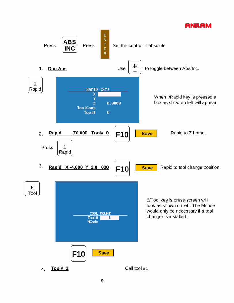
Dim Abs
ABSINC
1Rapid
Rapid Z0.000 Tool# 0 Rapid to Z home.
1Rapid
Rapid X -4.000 Y 2.0 000 Rapid to tool change position.
5Tool
Tool# 1 Call tool #1
Use to toggle between Abs/Inc. +_
When !/Rapid key is pressed a box as show on left will appear.
5/Tool key is press screen willlook as shown on left. The Mcode would only be necessary if a toolchanger is installed.
9.
F10 Save
F10 Save
F10 Save
ENTER
Press Press Set the control in absolute
1.
2.
Press
3.
4.

BasicDrill Zdepth -0.125 StartHgt 0.1000 Feed 10.0
When is pressed the screen will appear as above.
Zdepth = depth of hole.StartHgh = Distance above Surface you are drilling into.ReturnHgt = Distance above to retract to before moving to next hole.Feed = FeedrateTool# = Tool# may be entered here.
ENTER
F3 Drill
F3 Drill is selected this box will appear.These are your chose of how you are going to drill the hole , the first time wewill use Basic for the center drill , the second time we will use pecking for thedrill.
10.
F10 Save
ENTER
5.
11.
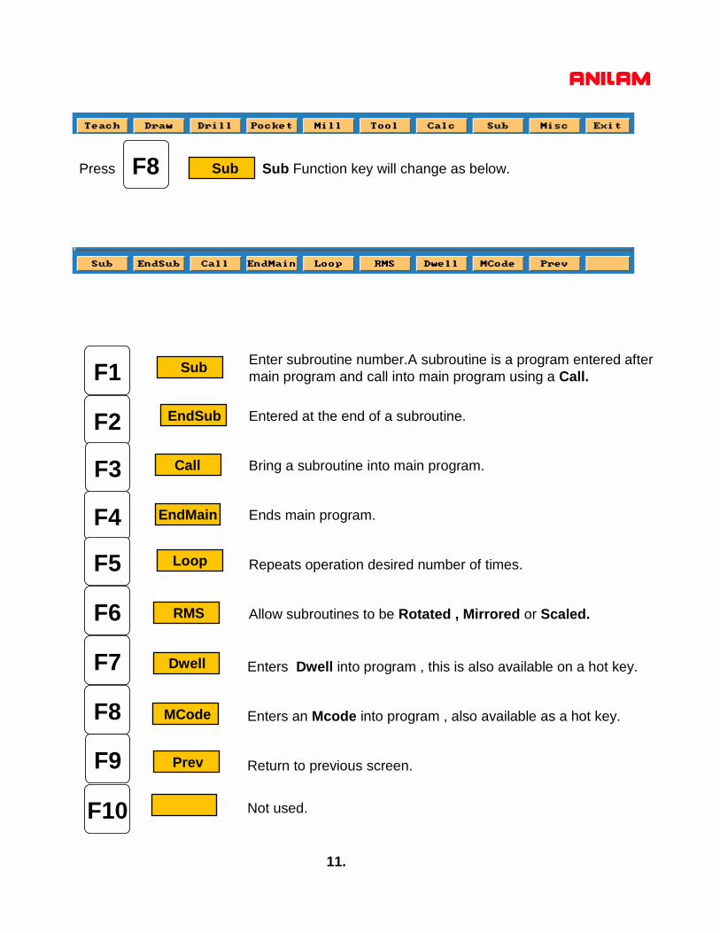
Press Sub Function key will change as below.
F1
F2
F6
F7
F8
F10
Sub
F3 Call
F4 EndMain
F5 Loop
RMS
MCode
Dwell
F9 Prev
EndSub
F8 Sub
Enter subroutine number.A subroutine is a program entered aftermain program and call into main program using a Call.
Entered at the end of a subroutine.
Bring a subroutine into main program.
Ends main program.
Repeats operation desired number of times.
Allow subroutines to be Rotated , Mirrored or Scaled.
Enters Dwell into program , this is also available on a hot key.
Enters an Mcode into program , also available as a hot key.
Return to previous screen.
Not used.

12.
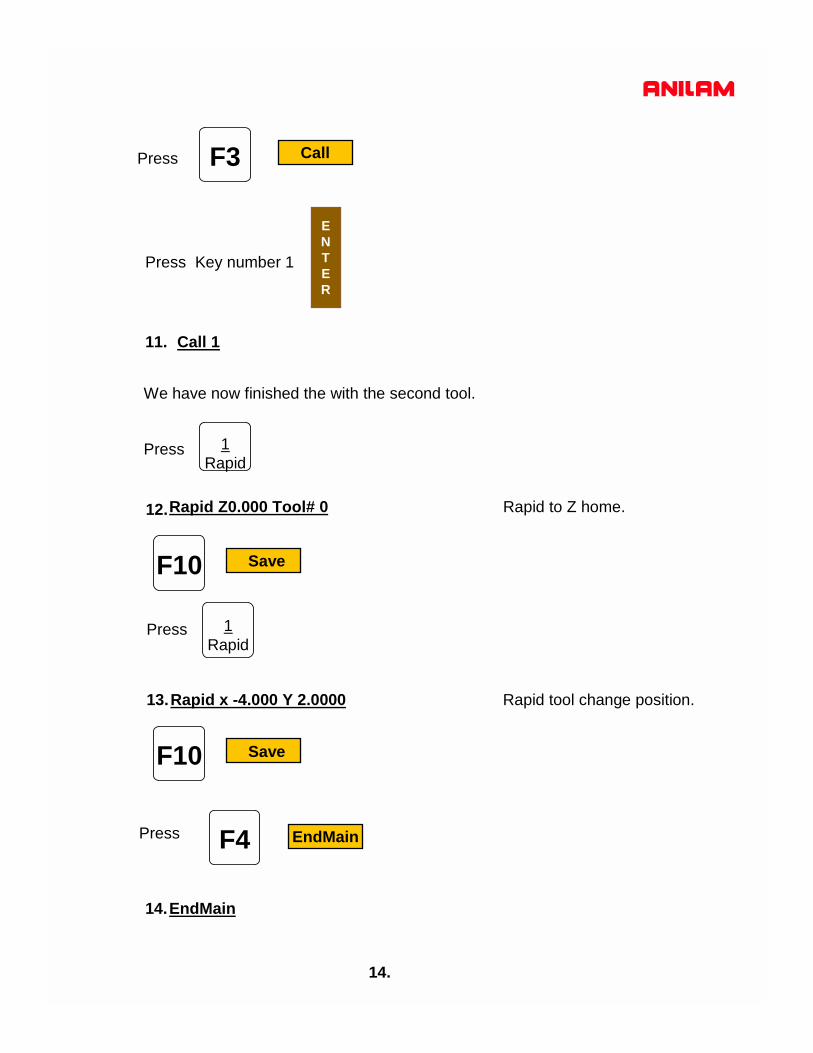
F3 CallPress
Press Key number 1
ENTER
Call 1
We have now finished the with the first tool.
Press 1Rapid
Rapid Z0.000 Tool# 0 Rapid to Z home.
Press 1Rapid
Rapid x -4.000 Y 2.0000 Rapid tool change position.
F10 Save
F10 Save
6.
7.
8.

13.
Press 5
Tool# 2 Activate tool #2
Press F3 Drill
Press down arrow key to high light Pecking , press
ENTER
F10 Save
Input values F10 Save
10. PeckDrill Zdepth -1.0000 StarHgt 0.1000 Peck 0.2500 Feed 12.0
9.
Tool
14.
F3 CallPress
Press Key number 1
ENTER
Call 1
We have now finished the with the second tool.
Press 1Rapid
Rapid Z0.000 Tool# 0 Rapid to Z home.
Press 1Rapid
F10 Save
F10 Save
F4 EndMainPress
EndMain
11.
12.
Rapid x -4.000 Y 2.0000 Rapid tool change position. 13.
14.

F1 SubPress press #1 key Press
Sub 1
Press 1Rapid
Rapid X 1.0000 Y -1.0000 press F10 saveRapid X 5.0000 press F10 saveRapid X 5.2500 Y -3.0000 press F10 saveRapid X 1.5000 press F10 save
F2 EndSubPress
EndSub
Program for this part is now complete.
15.
Drilling must now be turn off as soon as last hole is drilled
F9 PrevPress
F3 DrillPress
High light Drilling Off press
ENTER
F10 Save

Dim AbsRapid Z 0.0000 Tool# 0 (See note 2 below) Rapid X -4.0000 Y 2.0000Tool# 1BasicDrill ZDepth -0.1250 StartHgt 0.1000 Feed 10.0Call 1Rapid Z 0.0000 Tool# 0 ( See note 3 below ) Rapid X -4.0000 Y 2.0000Tool# 2PeckDrill ZDepth -1.0000 StartHgt 0.1000 Peck 0.2500 Feed 12.0Call 1Rapid Z 0.0000 Tool# 0 (See note 3 below)Rapid X -4.0000 Y 2.0000EndMain Sub 1Rapid X 1.0000 Y -1.0000Rapid X 5.0000Rapid X 5.2500 Y -3.0000Rapid X 1.5000Drilling OffEndSub
1.2.3.4.5.6.7.8.9.10.11.12.13.14.15.16.17.18.19.20.21.
This is above program will look in control.
16.
NoteIf running parts on a machine with Homing a fixture offset may be added to programat Line #2 or #3 to get to part zero.With Bed Mill Z0 Tool#0 not required , just move Z axis up plus to a convenient heightto change Tools.( I.e. Z5.0000.)
F2 Draw
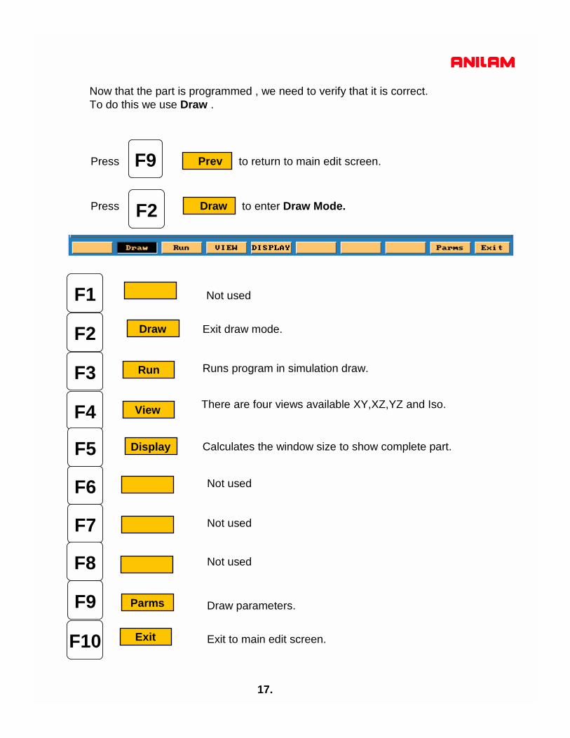
F9 PrevPress to return to main edit screen.
17.
Now that the part is programmed , we need to verify that it is correct.To do this we use Draw .
Press to enter Draw Mode.
F1
F2
F6
F7
F8
F9
F10
F3 Run
F4 View
F5 Display
Exit
Draw
Parms
Runs program in simulation draw.
Exit draw mode.
There are four views available XY,XZ,YZ and Iso.
Calculates the window size to show complete part.
Draw parameters.
Exit to main edit screen.
Not used
Not used
Not used
Not used
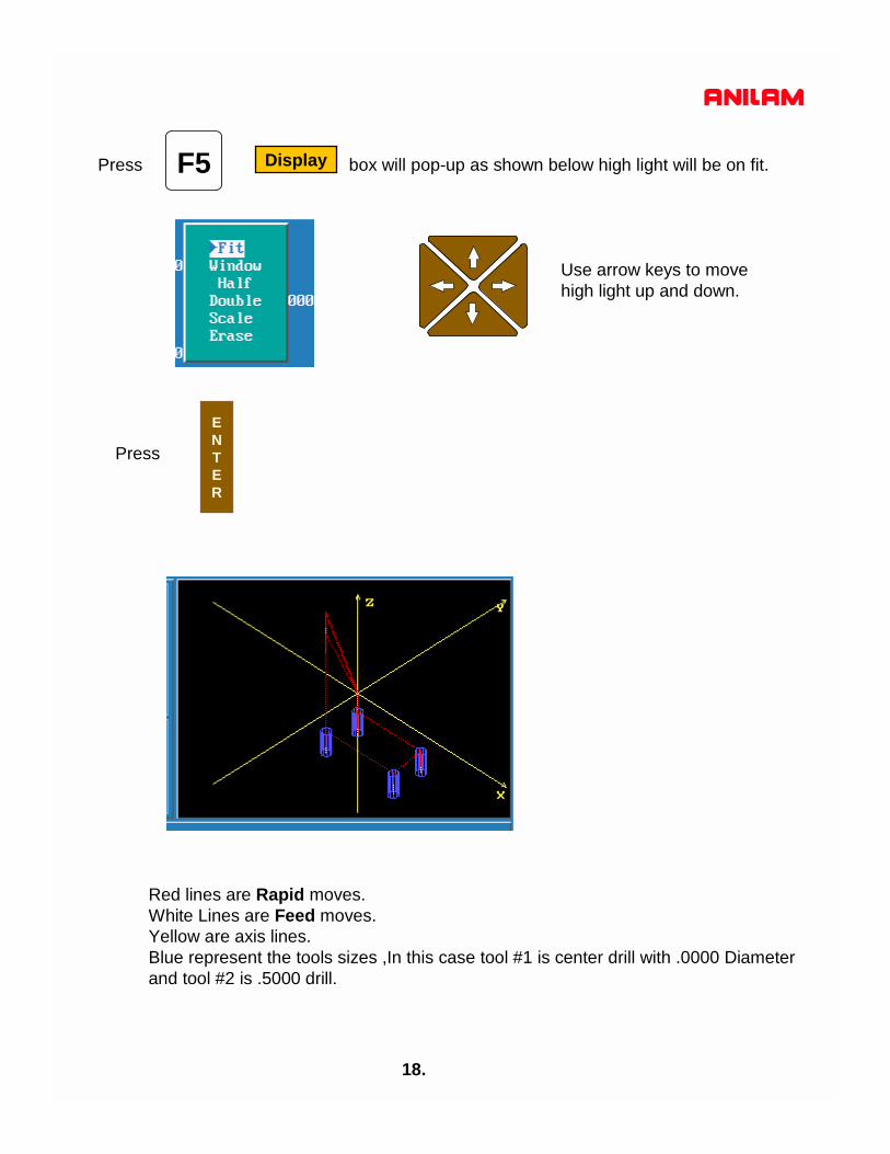
F5 DisplayPress box will pop-up as shown below high light will be on fit.
Press
ENTER
18.
Red lines are Rapid moves.White Lines are Feed moves.Yellow are axis lines.Blue represent the tools sizes ,In this case tool #1 is center drill with .0000 Diameterand tool #2 is .5000 drill.
Use arrow keys to movehigh light up and down.

19.
When or is press soft key will change as below.F3 Run
F1
F2
F6
F7
F8
F9
F10
F3 Motion
F4 Text
F5 Tool
S.Step
Cancel
Auto
Rapid
Start
Hold
Will run program all the way through.
Ever time Start is pressed runs one program line.
Runs a move ever time Start is pressed.
If high lighted will scroll text.
Will show tools if high lighted.
Displays Rapid moves when high lighted.
Starts draw moves one line in S Step or Motion.
Stop draw until Start is pressed.
Cancel current drawing.
Not used
F5 Display
20.
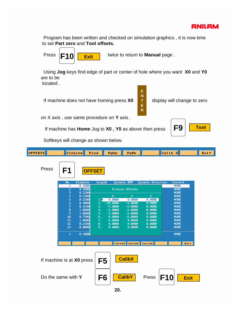
Program has been written and checked on simulation graphics , it is now time to set Part zero and Tool offsets.
Press twice to return to Manual page .
Using Jog keys find edge of part or center of hole where you want X0 and Y0are to belocated .
If machine does not have homing press X0 display will change to zero
on X axis , use same procedure on Y axis .
If machine has Home Jog to X0 , Y0 as above then press
Softkeys will change as shown below.
Press
If machine is at X0 press
Do the same with Y Press
F10 Exit
ENTER
F9 Tool
F5 CalibX
F1 OFFSET
F6 CalibY F10 Exit

21.
You are now back at the tool Page .The thing to do is set tool length Offsets.Check to see that Tool #0 is active .Put tool #1 into spindle jog down to top of part .Check to see that high light is on Tool #1 .
Now press
Move spindle up , put in tool #2 and repeat above process , until all tools offsets
are set and press .
Control is now back at Manual and ready to cut part.
Press
Put Tool #1 in spindle press
Machine will stop on Tool Change press
Machine will rapid X and Y position of first hole and then Z rapid to .1000above part . Next it will then feed to give depth and rapid back out of the holeand rapid to next hole and repeat process until all holes are drilled.
It will now on Tool Change and repeat process for tools #2 and #3.
F5 Calib Z
F10 Exit
F6 AUTO

3000M DXF Converter

1.
DXF file can be converted into 3000 machine programsusing the Offline software.
The DXF files are stored in the Program Page.When going to Program Page only .M file will be displayed,
press twice, this will display all files.F8 Display
High light DXF program
Press high light DXF Converter
F7 Log
Press
ENTER
If DXF is on disk it needs to be copied into C:\User directory.
press select A:
High light required DXF program press Copy to C:
F9 Utility
F9 Utility
2.
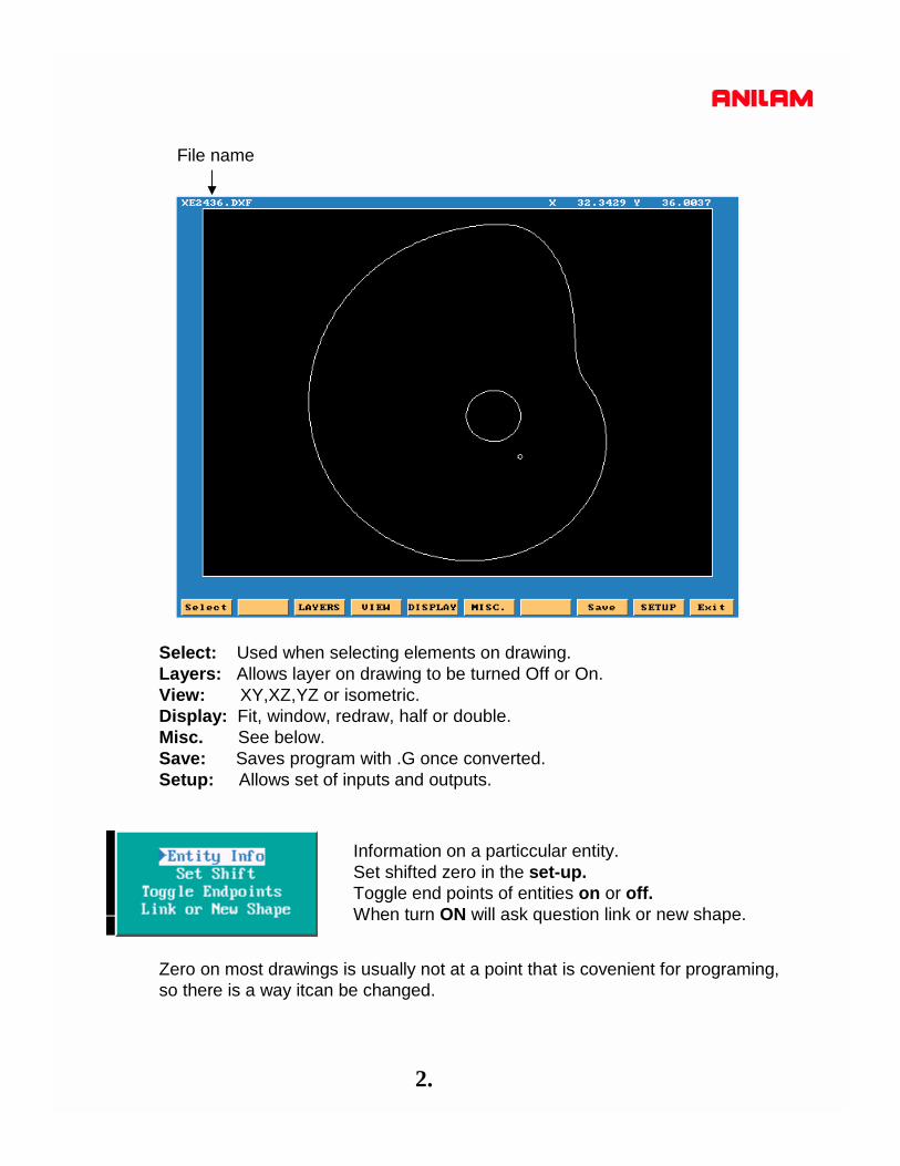
File name
Select: Used when selecting elements on drawing.Layers: Allows layer on drawing to be turned Off or On.View: XY,XZ,YZ or isometric.Display: Fit, window, redraw, half or double.Misc. See below.Save: Saves program with .G once converted.Setup: Allows set of inputs and outputs.
Zero on most drawings is usually not at a point that is covenient for programing,so there is a way itcan be changed.
Information on a particcular entity.Set shifted zero in the set-up.Toggle end points of entities on or off.When turn ON will ask question link or new shape.

3.
In the case of current drawing, the center of the hole in center of part is the bestpoint X0 Y0. There are two methods find new zero’s from an entity on drawing.1. To do this Press the Ctlr key and hold it down put mouse point on to circle andpress left mouse key, it will change to yellow, release keys.2. Press key select press ENTER select entity using mouse
it will turn yellowAt the bottom of screen X, Y, and Z cordinate will appear and also circle diameter.
X Y ZCircle Diameter
F9 SETUP Press
ENTER
Now press ALT key and letter T at the same time first method or press ENTER.
This will in put these coordinates in to the SETUP and change X0 Y0 to the center of hole.
Press
Program nameImported X shiftImported Y shiftAbsolule/increamentalSmart/OverwriteStarting subroutine numberWarns if elements done meetRe-calculates intesectsDecimal out putCreate a main programInch / Metric / NoneConvert polyline to arc/prompt/none
MISC
MISC

4.
F10 ExitPress
Press ALTkey and letter Fkey at the same time, this will mark the end of eachelement.
F6 Compress
Press high light Window press
A box will appear on screen move over using
press position box as shown below press
ENTER
F5 DISPLAY
ENTER

5.
F1 SelectPress point mouse arrow to lower end of a line as shown
and pess left mouse key. Line will turn green as above and put a number at low end of line, the position of the number is the start point.Now point to the line below it and press left mouse key, all off the line will be come green.
Press ALT key and letter Fkey at the same time the end of line markerswill disappear.
Press press Part will appear at full size on screenF5 DISPLAY
ENTER

6.
ENTER
F10 ExitPress
F8 SavePress
Press Y it will now return to Program page.
High light .M file press F4 Edit
F1Press or

7.
High light .M file press F4 Edit
Start of program
End of program
Program has to be Edited , to put in tool changes or cutter comp and Z moves.
8.
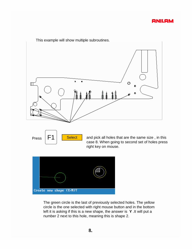
This example will show multiple subroutines.
and pick all holes that are the same size , in thiscase 8. When going to second set of holes pressright key on mouse.
F1 SelectPress
The green circle is the last of previously selected holes. The yellowcircle is the one selected with right mouse button and in the bottomleft it is asking if this is a new shape, the answer is Y .It will put a number 2 next to this hole, meaning this is shape 2.

9.
The print below shows the four shapes of the different sizes holes.
Press F8 Save
F10 ExitPress
1
2 34
5
67 8
1
21 2
1
ENTER
Press Y it will now return to Program page.F1Press or

10.
Below show program as it comes from DXF converter.Some work will have to be done in main program to center drill and drill and these holes.
Subroutine calls
Subroutine for positions of the eight holes numbered in black.
Subroutine for positions of the two holes numbered in green.
Subroutine for positions of the two holes numbered in blue.
Subroutine for positions of the one hole numbered in light blue.
11.
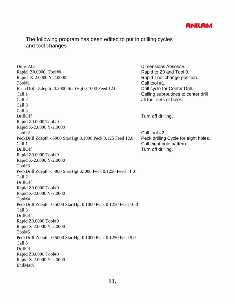
The following program has been edited to put in drilling cyclesand tool changes
Dims AbsRapid Z0.0000 Tool#0Rapid X-2.0000 Y-2.0000Tool#1BasicDrill Zdepth -0.2000 StartHgt 0.1000 Feed 12.0Call 1Call 2Call 3Call 4DrillOffRapid Z0.0000 Tool#0Rapid X-2.0000 Y-2.0000Tool#2PeckDrill Zdepth -.5000 StartHgt 0.1000 Peck 0.125 Feed 12.0Call 1DrillOffRapid Z0.0000 Tool#0Rapid X-2.0000 Y-2.0000Tool#3PeckDrill Zdepth -.5000 StartHgt 0.!000 Peck 0.1250 Feed 11.0Call 2DrillOffRapid Z0.0000 Tool#0Rapid X-2.0000 Y-2.0000Tool#4PeckDrill Zdepth -0.5000 StartHgt 0.1000 Peck 0.1250 Feed 10.0Call 3DrillOffRapid Z0.0000 Tool#0Rapid X-2.0000 Y-2.0000Tool#5 PeckDrill Zdepth -0.5000 StartHgt 0.1000 Peck 0.1250 Feed 9.0Call 5DrillOffRapid Z0.0000 Tool#0Rapid X-2.0000 Y-2.0000EndMain
Dimensions Absolute.Rapid to Z0 and Tool 0.Rapid Tool change position.Call tool #1.Drill cycle for Center Drill.Calling subroutines to center drill all four sets of holes.
Turn off drilling.
Call tool #2.Peck drilling Cycle for eight holes.Call eight hole pattern.Turn off drilling.

12.
In this example of a full drawing and how to turn off unnecessaryinformation ,such as dimensions etc.
The first thing to do is turn off some of the layers so as to leave onlythe part.

13.
F3 LayersPress
High light Toggle Layers press
ENTER
Put high light on layers not required and press to turn OFF.
ENTER
In the drawing shown the only layer left on is #11
14.
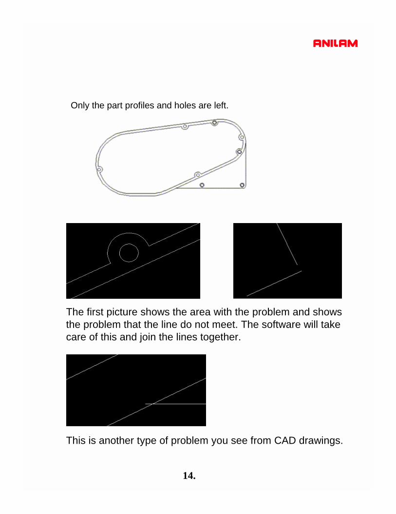
Only the part profiles and holes are left.
The first picture shows the area with the problem and showsthe problem that the line do not meet. The software will take care of this and join the lines together.
This is another type of problem you see from CAD drawings.