angliportfolio.weebly.comangliportfolio.weebly.com/.../1/9/4/0/19407879/ee.docx · Web viewTotal...
27
0 Aerodynamics of Wingtip Devices Simon Li Glenforest Secondary School
Transcript of angliportfolio.weebly.comangliportfolio.weebly.com/.../1/9/4/0/19407879/ee.docx · Web viewTotal...
0
Aerodynamics of Wingtip Devices
Simon Li
Glenforest Secondary School
Physics Extended Essay
Total Word Count: 3943

1
Table of Contents
Abstract…………………………………………………………………………….…….2
Introduction…………………...…………………………………………………….……3
Background and Research………………………………………………………………...3
Research Questions…….…………..……………………………………………………..7
Hypothesis………………………………………………………………………….……..7
Experiment Overview……………....……………………………………………………..7
Variables…………………….…………………………………………………………….7
Materials……….………………………………………………………………………….8
Procedure…………………...……………………………..………………………………8
Results……………………………………………………………………………………11
Conclusion and Evaluation………………………………………………………………15
Bibliography…………...……………………………………………………………..….16

2
Abstract
This experiment will investigate into the effectiveness of wingtip devices, also known as
winglets, which help reduce drag by diminishing wingtip vortices and improve fuel
efficiency. The experiment will test three variants of winglets: blended winglets, wingtip
fencings, and raked wingtips. A control wingtip without winglets will also be tested. The
results will be compared against each other, and to real world statistics and applications
to answer the question, To what extent do different typed of winglets affect the strength
of wingtip vortices? The raked wingtip is predicted to be the most effective because by
acting as an extension of the wings, it may have less negative disturbances to the
aerodynamic properties than the other winglets.
This experiment is aimed at proving that wingtip devices do work as intended. It will also
prove the relative effectiveness of the winglets as observed in real world operation. The
experiment will take place in a 1:500 scale. The results will not be extrapolated to match
those of full scale tests. This is due to the limited equipment and budget available for this
experiment. To successfully mimic full scale operation of the winglets in 1:500 scale,
reliable sources such as airframe manufacturer websites and patents will be among the
resources in the research process. These sources will provide detailed dimensions and
allow accurate construction of the mini winglets.
At the end of the investigation, the visualizations of the airflow patterns will provide
undoubted prove that the wingtip devices improve the efficiency of the wings. The raked
wingtip will have the best results in diminishing wingtip vortices. The blended wingtips
and wingtip fencings will show similar, but lower improvements to airflow than the raked
wingtip.

3
Introduction
The aerospace industry is expanding at a faster rate than ever before. The driving
force behind this rapidly developing industry is the constant technological advancements
that make flying a more efficient way of travel. This report will investigate one of these
technologies, wingtip devices. Wingtip devices, also called winglets, were first developed
in the 1970s [Understanding Winglet Technologies, Page 1]. They are designed to reduce
drag formed at the wingtips of aircrafts, thereby increasing fuel efficiency. They way
these wingtip devices manipulate air flow over the wingtips is incredibly intriguing.
Modern aircrafts are equipped with a variety of winglets, each with different structural
features. In this report, these different types of winglets will be compared to determine
how effective they are relative to each other. The experimental data will be compared
with real world applications of these winglets to determine the validity of the results. This
process will answer the question: To what extent do different typed of winglets affect
the strength of wingtip vortices? The raked wingtip is predicted to be the most effective
due to its simplicity in design with less turbulent disturbances to the airflow over the
wingtips.
Background and Research
For many decades after the first powered flight, wingtip designs remained the
same. Wingtips were simply a flat ending of the wing with no added features. However,
as larger and faster airplanes emerge, so do their wake turbulence. Wake turbulence
occurs when an aircraft disturbs the air that it passes through, and leaves a trail of
unstable air behind it. It is discovered that the majority of the wake turbulence generated
by an aircraft does not originate from the inner portions of the wings, but rather the
wingtips [Pendelton]. Heavy aircrafts with large wings can generate wake turbulence
strong enough to flip lighter aircrafts many miles behind it. This hazard has caused many
accidents and raised concerns about manufacturing and designing larger aircrafts to
support the booming demand for air travel.

4
Wake turbulence that result from wingtips of aircrafts is often in the form of
wingtip vortices. The wingtip produces a horizontal rotating column of air that has
enough energy to last for minutes [Pendelton] . The cause of the phenomenon originates
from the fundamental design of aircraft wings. The wings of airplanes are shaped to
allow air above the wing to flow faster than the air beneath it. The curvature of the wings
increases the distance travelled by the air per period of time above the wings. This is an
application of Bernoulli’s law to create an area of low pressure on top of the wing and
high pressure beneath it[Understanding Winglet Technologies, Page 2]. Since high
pressure fluids have a high tendency of flowing towards area of lower pressure, the air
beneath the wing pushes upwards to create lift. However, at the wingtips, higher pressure
air beneath the wing is able to roll around the wingtips to the top of the wing. Relative to
the aircraft, the airstream that initially only had a vector opposite to the aircraft’s motion,
now has an additional rotational vector [Understanding Winglet Technologies, Page 2].
Through vector addition, a rotating column of air forms behind the wingtip, such that the
direction of rotation is towards the fuselage of the aircraft. This phenomenon is shown by
the diagram below.
The escaped air from beneath the wing is no longer generating lift. The reduction of lift
will cause the aircraft to increase its angle of attack, abbreviated AOA. AOA is the angle
of the wings in relation to the oncoming air [Induced Drag]. An increase in AOA means
the aircraft is closer to the stalling angle, where the wings no longer generate lift. Also,
increasing AOA exposed more area of the aircraft to the airstream, resulting in more drag
due to air resistance [Induced Drag]. This drag is known as parasitic drag. Furthermore,
since the lift vector is perpendicular to the wing, the force generated by the wings at a
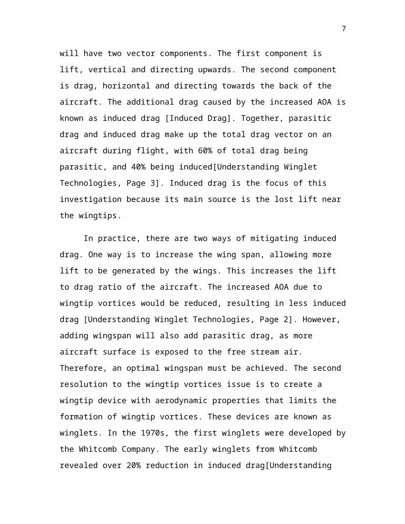
positive AOA will have two vector components. The first component is lift, vertical and

5
directing upwards. The second component is drag, horizontal and directing towards the
back of the aircraft. The additional drag caused by the increased AOA is known as
induced drag [Induced Drag]. Together, parasitic drag and induced drag make up the total
drag vector on an aircraft during flight, with 60% of total drag being parasitic, and 40%
being induced[Understanding Winglet Technologies, Page 3]. Induced drag is the focus
of this investigation because its main source is the lost lift near the wingtips.
In practice, there are two ways of mitigating induced drag. One way is to increase
the wing span, allowing more lift to be generated by the wings. This increases the lift to
drag ratio of the aircraft. The increased AOA due to wingtip vortices would be reduced,
resulting in less induced drag [Understanding Winglet Technologies, Page 2]. However,
adding wingspan will also add parasitic drag, as more aircraft surface is exposed to the
free stream air. Therefore, an optimal wingspan must be achieved. The second resolution
to the wingtip vortices issue is to create a wingtip device with aerodynamic properties
that limits the formation of wingtip vortices. These devices are known as winglets. In the
1970s, the first winglets were developed by the Whitcomb Company. The early winglets
from Whitcomb revealed over 20% reduction in induced drag[Understanding Winglet
Technologies, Page 1]. Today, there are many variations of winglets being used on
aircrafts around the world. The commercial aircraft sector of the European Aeronautic
Defense and Aerospace Company, also known as Airbus, incorporates wingtip fencing on
many of their production models. These types of winglets are seen on the A320 and the
A380 [balint01]. Wingtip fencing is a plate of aluminum cut
into an arrow like design, shown to the right. It is placed
perpendicular to the wing at the wingtip such that the fencing
extends above and below the wing. This design reduces
airflow rolling around the wingtips and effectively reduces wingtip vortices.
Another variant of winglets was designed contemporary to Airbus’s wingtip
fencings. Boeing developed the blended wingtips, which are currently installed on the
New Generation 737s and the Boeing 767-300 [balint01]. Unlike wingtip fencings,
blended winglets do not extend beneath wing level. The wing of the aircraft goes through

6
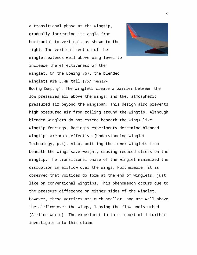
a transitional phase at the wingtip, gradually increasing its
angle from horizontal to vertical, as shown to the right. The
vertical section of the winglet extends well above wing level
to increase the effectiveness of the winglet. On the Boeing
767, the blended winglets are 3.4m tall [767 family-
Boeing Company]. The winglets create a barrier between the low pressured air above the
wings, and the. atmospheric pressured air beyond the wingspan. This design also prevents
high pressured air from rolling around the wingtip. Although blended winglets do not
extend beneath the wings like wingtip fencings, Boeing’s experiments determine blended
wingtips are more effective [Understanding Winglet Technology, p.4]. Also, omitting the
lower winglets from beneath the wings save weight, causing reduced stress on the
wingtip. The transitional phase of the winglet minimized the disruption in airflow over
the wings. Furthermore, it is observed that vortices do form at the end of winglets, just
like on conventional wingtips. This phenomenon occurs due to the pressure difference on
either sides of the winglet. However, these vortices are much smaller, and are well above
the airflow over the wings, leaving the flow undisturbed [Airline World]. The experiment
in this report will further investigate into this claim.
In the past decade, Boeing designed another type of winglets, the raked wingtips. They
have been installed on most of Boeing’s aircrafts developed in the 21 st century as a
replacement for blended winglets. Some of the aircrafts operating with raked winglets are
the -400 series of the Boeing 767, Boeing 777, and the newest Boeing aircraft, the 787
[Airline World]. Raked wingtips are similar to an extension of wingspan. Unlike a
normal extension, the sweep angle of the wingtip is greater than that of the wing. The
higher sweep angle along with a sharper tip allows greater lift while minimizing
increased parasitic drag. Furthermore, since more lift is generated further aft of the wing
due to the wingtips, the aircraft will fly with decreased angle of attack. A decrease in
angle of attack will reduce the strength of wingtip vortices, which means less induced
drag. Raked wingtips are becoming more common in modern aircraft design due to their
effectiveness in diminishing induced drag, and their rather simple design [Larry L
Harrick, p.11]. When designing the B767-400, Boeing extended the wingspan by 4.3m
7
from the -300 series to 51.9m, according the specifications of the different variants of
Boeing 767s on the Boeing website [767 family – Boeing Company]. The 4.3m is due to
the addition of the raked winglets. The fuselage diameter is 4.7m. Therefore, the
wingspan without the fuselage, which is not part of the wing, is 51.9−4.7=47.2 m. 4.3m
of the 47m, or approximately 11% of the wings is comprised of raked winglets. This
figure is useful in the experiment when constructing the raked wingtips.
Research question
To what extent do different typed of winglets affect the strength of wingtip vortices?
Hypothesis
It is expected that the raked wingtip will be the most effective out of all of the wingtips
because it is the most advanced type of wingtip in the world.
Experiment design overview
Since the experiment will be conducted with small scale models, it would be inaccurate
to extrapolate the results to attempt to match full scale results. Therefore, the data will
only be compared to each other to determine relative effectiveness. The experiment will
take place inside a small wind tunnel. Model aircrafts with different winglets attached
will be secured in the free stream. Smoke passing through the wind tunnel will be
adjusted to flow over the winglets to produce a visual image of the airflow over the
wingtips. Videos of different experiments will be analyzed carefully to produce the final
results.
Variables
Dependent – Types of winglets
Independent – size of wingtip vortices
Control – Constant wind speed, same aircraft model, constant wind tunnel structure, same
angle of attack

8
Materials
1 extra large piece of 1 inch thick Styrofoam
1 large piece of acrylic glass
1 bag of incense sticks
2 model Boeing 767 (1 with blended winglets, 1 with no winglets)
Table Saw
Duct tape
Liquid Glue
Large piece of cardboard
2 cores of toilet paper rolls
0.5m of string
1 box fan
4 boxes of drinking straws
Black construction paper
Black paint
2mm thin hard plastic
Scissors
Precision knife
Digital Camera
Tripod
Procedure
Building the wind tunnel
1. Cut an area of Styrofoam with length of 1.5m and width greater than that of the
box fan.
2. Secure the Styrofoam board on a table
9
3. Cut two pieces of acrylic glass using the table saw, each with length of 1.5m and a
width 3cm greater than the height of the box fan. These are the walls of the wind
tunnel.
4. Cut another piece of acrylic glass with length of 1.5m and a width greater than
that of the box fan. This is the ceiling of the wind tunnel.
5. Place the box fan at one end of the length of Styrofoam.
6. Mark the edges of the fan on the Styrofoam, and cut a 2cm deep slit along the
length of the board, ensure both slits maintain the same separation along the entire
board. Ensure the slits are not deep enough to cut clean through the Styrofoam
board.
7. Squeeze the two wind tunnel walls into the slits. The walls should be touching the
sides of the fan.
8. Use duct tape along each edge of the fan to secure it to the walls and Styrofoam
base, and to ensure an air tight fit.
9. Tape pieces of Styrofoam on top of the fan if the walls extend beyond the height
of the fan.
10. Cut straws into 5cm lengths
11. Place cut straws parallel to each other and make bundles by taping them together.
12. Place bundles of straws at the opposite end of the wind tunnel from the fan to
create a honeycomb structures. This structure will ensure linear air flow in the
wind tunnel and eliminate any turbulent air entering the tunnel.
13. Fill up the opposite end of the tunnel with straws until the entire end of the tunnel
is blocked by the honeycomb structure.
14. Place the ceiling piece of the wind tunnel over the entire structure.
15. Cut a piece of construction paper 1.5m in length and width the same as the height
of the wall. Paste it onto one of the walls of the tunnel. The black paper will allow
better visualization of the white smoke.
16. Cut another piece of construction paper 1.5m in length and ¼ of the height of the
wall in width. Use white crayon to mark every 2cm along the length and paste it
onto the other wall of the tunnel. This wall is the viewing wall.
10
17. Place aluminum foil over the Styrofoam foundation of the tunnel to prevent a fire
in case incense sticks touch the Styrofoam.
18. Optimize wind speed in the tunnel. If winds are fast, the smoke becomes less
visible. If winds are slow, the smoke is more susceptible to small areas of
turbulence. If the fan blades have only one speed, adjust the size of the outlet by
limiting the size of the intake with the divergence of parts of the fan’s intake to
the air outside the wind tunnel.
Conducting the experiment
1. Take real world dimension of wingtip fencings and raked wingtips and divide by
500 to adjust for the 1:500 aircraft model.
2. Download computer image of the winglets and shrink them to appear with the
same calculated dimensions on the monitor.
3. Trace the outlines of the winglets onto the transparent plastic.
4. Cut the plastic outline.
5. Paste the winglets on the model without winglets.
6. Cut a piece of cardboard with length of the fuselage of the model, and width twice
the diameter of the fuselage. Paste this on top of a toilet paper core
7. Pitch the aircraft model to an angle where the tail touches the ground, then paste it
onto the cardboard.
8. Paint the side of the aircraft facing the observer black, to allow better
visualization of the white smoke patterns.
9. Repeat steps 6-8 with the other aircraft model.
10. Set up camera tripod and zoom for the best view. Ensure this camera position
remains the same for the entire experiment.
11. Light up 4 incense sticks and stick them through the honeycomb structure into the
tunnel. Ensure the smoke will pass through the general area of the wingtip.
12. Place the aircraft with no winglets into the tunnel and turn on the fan.
13. Record a video of at least 15seconds of the smoke patterns.
14. Repeat steps 8 and 9 with the three other winglets installed.
11
15. Analyze the video by comparing the smoke patterns to determine the
effectiveness of each wingtip structure. Using the white reference lines, measure
and compare the period of rotation observed in the smoke pattern. As the smoke
twists, the side view will provide the top and bottom point of rotation. The
distance between these two points is half a period
Results
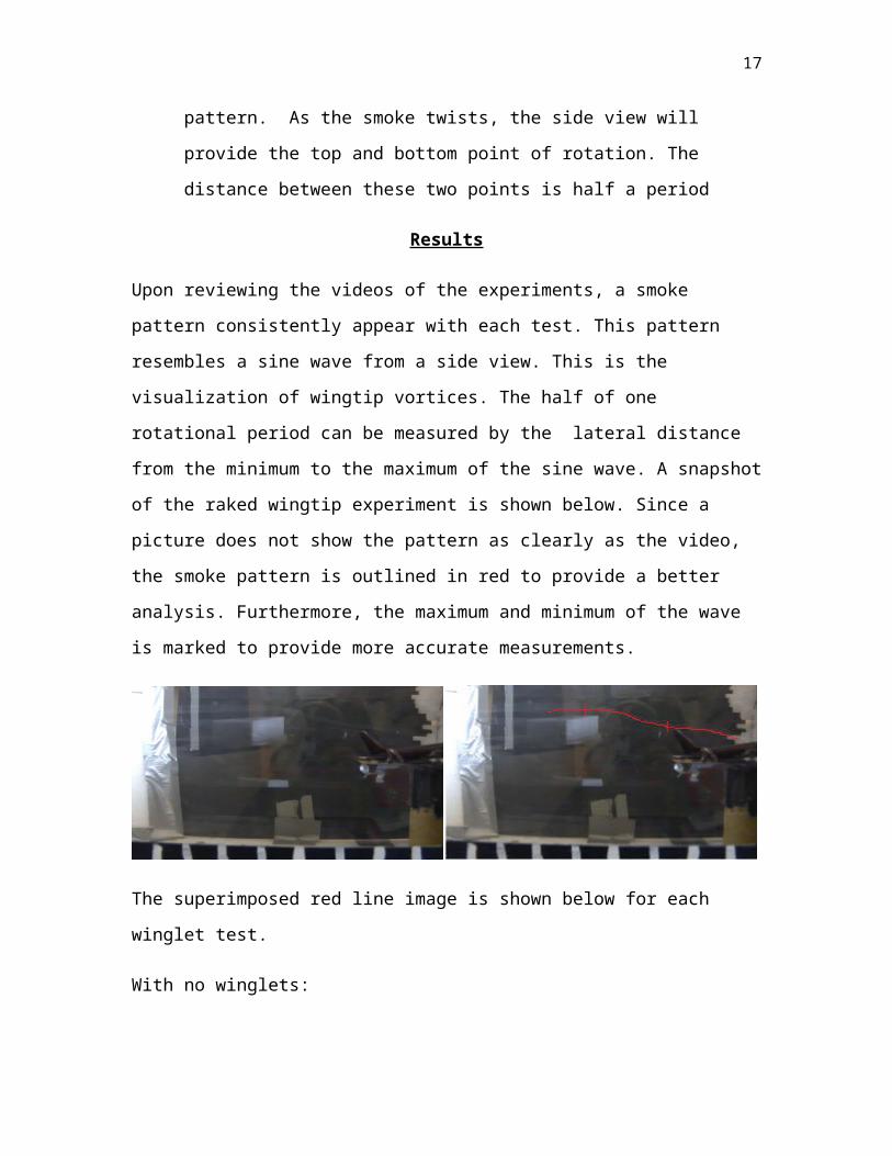
Upon reviewing the videos of the experiments, a smoke pattern consistently appear with
each test. This pattern resembles a sine wave from a side view. This is the visualization of
wingtip vortices. The half of one rotational period can be measured by the lateral
distance from the minimum to the maximum of the sine wave. A snapshot of the raked
wingtip experiment is shown below. Since a picture does not show the pattern as clearly
as the video, the smoke pattern is outlined in red to provide a better analysis.
Furthermore, the maximum and minimum of the wave is marked to provide more
accurate measurements.
The superimposed red line image is shown below for each winglet test.
With no winglets:

12
Blended Winglets:
Wingtip Fencing:
Raked Winglets:
The maximum and minimum of the rotation is better visualized, so raw data can be collected as
shown below:
Winglet Half Period (cm) ±0.5cm Full period (cm) ±1.0cm
None (Control) 2.0 4.0
Blended Winglet 2.5 5.0
Wingtip Fencing 2.7 5.4
Raked Winglets 4.2 8.4
A graph can be produced from this set of data to see the extent of the impact of different
types of winglets.
13
The results above show a significant change in the energy of the wingtip vortices with
different winglets. The vortices generated by the raked wingtip take twice the distance to
make one full revolution. Since the wind speed in the tunnel is constant, the rotation
speed of the vortices in different test may be compared to each other. The equation d = vt
will be applied to both the rotational vector, and the vector of the wind flow in the tunnel.
The wind speed for different tests is constant, thus v is constant.
Let t be the time it takes the control vortices to make one full rotation.
Blended wingtip period: 5.04.0
t
Wingtip Fencing period: 5.44.0
t
Raked wingtip period: 8.44.0
t
The difference in the diameter of the vortices is very minuscule. Therefore, the vortices
make one full rotation along a circumference of the same size. With distance constant,
relative rotational velocity is calculated.
Let v be the rotational velocity of the control wingtip.
14
Blended wingtip velocity: 4.05.0
v=80 % v
Wingtip Fencing velocity: 4.05.4
v=74 %v
Raked Wingtip velocity: 4.08.4
v=48 % v
Using the energy equation E=12
m v2, Energy in Joules is proportional to the square of
velocity in meters per second. With a 20% reduction in speed, or 80% of the original
speed, rotational energy would experience a 36% reduction. This result means blended
wingtip diminishes the energy lost to wingtip vortices by 36%. Using the same method,
wingtip fencings reduce the energy of wingtip vortices by 45% while blended wingtips
reduce vortices energy by 77%. A loss in the rotational speed in the vortices also means
less volume of air is rolling around the wingtips. More lift is generated and less angle of
attack is required, thus reducing induced drag. These figures can be represented on a
graph, as shown below.

15
It is clear from the graphs that raked wingtip provides the greatest reduction in wingtip
vortices and thus, it is the most effective winglet for diminishing induced drag. The
experimental results reveal a slightly greater effectiveness in wingtip fencing than
blended wingtips. However, due to the uncertainties presented in the data, the advantage
cannot be confirmed. Furthermore, all wingtips showed improvement for reducing
wingtip vortices, which is the result expected before conducting this experiment. This
find further confirms the validity of the method used for this investigation.
To further validate these results, they will be compared to real world application of
different variants of winglets. The similar effectiveness of the blended winglets and the
wingtip fencings replicates the fierce competition between the Boeing 737 with blended
wingtips, and Airbus A320 with wingtip fencings. Both these aircrafts have similar
characteristics and advantages in the aerospace industry, and earned similar numbers of
airline orders. The huge advantage of the raked wingtip revealed in the experiment
explains why the raked wingtip is used on most of Boeing’s new airplanes, driving
blended winglets to obsolescence. Boeing shows raked wingtips generate 5.5% better fuel
economy for the Boeing 777, while blended winglets generates only 3.5% for the Boeing
737 [Airline World]. With close similarity to real world applications, the results in this
experiment can be considered valid.
Conclusion and Evaluation
This experiment effectively answers the research questions: To what extent do different
typed of winglets affect the strength of wingtip vortices? The results determine that raked
wingtips are the most effective at limiting wingtip vortices. This result was exactly what
the thesis predicted. Furthermore, blended wingtips and wingtip fencings also
significantly weakens the vortices, to a lesser degree. The weaker the vortices, the less
drag are induced on the aircraft. To further validate these results, they will be compared
to real world application of different variants of winglets. The similar effectiveness of the
blended winglets and the wingtip fencings replicates the fierce competition between the
Boeing 737 with blended wingtips, and Airbus A320 with wingtip fencings. Both these
aircrafts have similar characteristics and advantages in the aerospace industry, and earned
similar numbers of airline orders. The huge advantage of the raked wingtip revealed in

16
the experiment explains why the raked wingtip is used on most of Boeing’s new
airplanes, driving blended winglets to obsolescence. Boeing shows raked wingtips
generate 5.5% better fuel economy for the Boeing 777, while blended winglets generates
only 3.5% for the Boeing 737 [Airline World]. With close similarity to real world
applications, the results in this experiment can be considered valid.
There are, however, a few aspects of the experiment that could be improved for more
sophisticated testing. There are a variety of equipment improvements if enough funding
is provided. Some improvements include larger models, greater fan speed, longer wind
tunnel, and a smoke wand. These will provide better visualizations of the vortices and
more accurate measurements. For better comparison of the vortices, more camera angles
should be used. Also, if a sophisticated filming program is available, combine the videos
together to better visualize the differences.
This experiment shows how a simple wingtip structure could improve efficiency so
significantly. With 40% of total drag on an aircraft being induced drag, engineers will
continue to research and develop better winglets. One major breakthrough in winglet
design is capable of achieving record breaking fuel efficiency and providing a great
advantage over competing airframes. It will also significantly reduce emission caused by
air travel, and make this mode of transportation the most preferable and economical way
to travel. With the implementation of these winglets in real world, fuel efficiency and
environmental control can be greatly improved.
17
Sources
"767 Family." The Boeing Company. 9 Aug. 2011.
<http://boeing.net/commercial/767family /400/400_3.html>
"Aero 17 - Blended Winglets."The Boeing Company. 8 Aug. 2011.
<http://www.boeing.com
/commercial/aeromagazine/aero_17/winglet_story.html>
balint01. "Aircraft Winglets."Airline world. 8 Aug. 2011.
<http://airlineworld.wordpress.com /2008/10/01/aircraft-winglets/>
"Induced Drag." Professional Pilot. N.p., n.d. Web. 5 Aug. 2011.
<http://selair.selkirk.ca /Training/Aerodynamics/induced.htm>
Larry L Herrick et al. ”Blunt-Leading-Edge Raked Wingtips”. US Patent
6089502. July 18, 2000.
Pendelton, Linda. "Wake Turbulence- An Invisible Enemy." AVweb » The
World's Premier Independent Aviation News Resource. Web. 3 Aug. 2011.
<http://www.avweb.com /news/airman/183095-1.html>
"Understanding Winglet Technology." Smart Cockpit.. 2 Aug. 2011.
<www.smartcockpit.com
/data/pdfs/flightops/aerodynamics/Understanding_Winglets_Technology.p
df>