Angkor Wat, Cambodia - SEAoOseaoo.org/downloads/Presentations_CONF/2014_seaoo_conference... · ASTM...
18
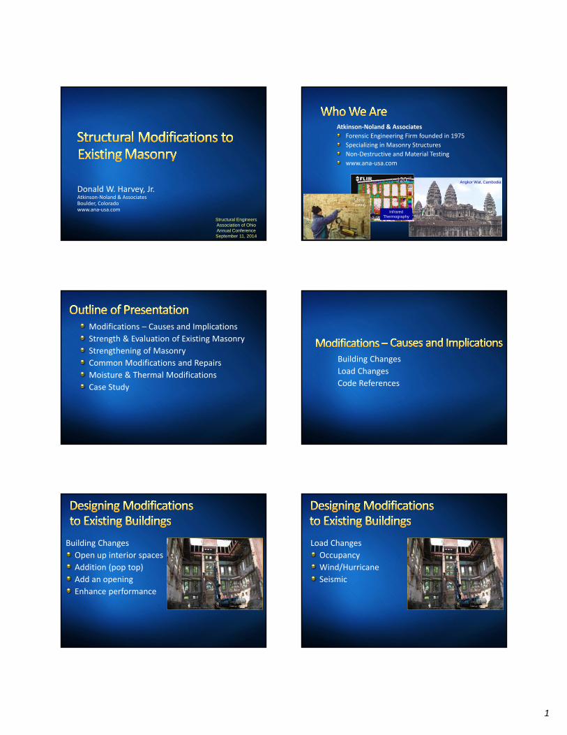
1 Donald W. Harvey, Jr. Atkinson‐Noland & Associates Boulder, Colorado www.ana‐usa.com Structural Engineers Association of Ohio Annual Conference September 11, 2014 Atkinson‐Noland & Associates Forensic Engineering Firm founded in 1975 Specializing in Masonry Structures Non‐Destructive and Material Testing www.ana‐usa.com Angkor Wat, Cambodia Infrared Thermography Shear Testing Modifications – Causes and Implications Strength & Evaluation of Existing Masonry Strengthening of Masonry Common Modifications and Repairs Moisture & Thermal Modifications Case Study Building Changes Load Changes Code References Building Changes Open up interior spaces Addition (pop top) Add an opening Enhance performance Load Changes Occupancy Wind/Hurricane Seismic
Transcript of Angkor Wat, Cambodia - SEAoOseaoo.org/downloads/Presentations_CONF/2014_seaoo_conference... · ASTM...
1
Donald W. Harvey, Jr.Atkinson‐Noland & AssociatesBoulder, Coloradowww.ana‐usa.com
Structural Engineers Association of Ohio Annual ConferenceSeptember 11, 2014
Atkinson‐Noland & Associates
Forensic Engineering Firm founded in 1975
Specializing in Masonry Structures
Non‐Destructive and Material Testing
www.ana‐usa.com
Angkor Wat, Cambodia
Infrared Thermography
Shear Testing
Modifications – Causes and Implications
Strength & Evaluation of Existing Masonry
Strengthening of Masonry
Common Modifications and Repairs
Moisture & Thermal Modifications
Case Study
Building Changes
Load Changes
Code References
Building Changes
Open up interior spaces
Addition (pop top)
Add an opening
Enhance performance
Load Changes
Occupancy
Wind/Hurricane
Seismic
2
International Building Code
International Existing Building Code
MSJC Empirical Requirements
ASCE 41‐06 guidelines
For many years…
25% ‐ 50% ruleProject cost <25% of building worth? Upgrades negotiable
25% to 50%? All new work to meet code
> 50%? Bring entire building into code compliance
Chapter 34: Existing Structures
Primary goals“Dangerous” conditions must be mitigated
New work cannot introduce “dangerous” conditions
New work must meet code
Repair using like materials
OK to meet IEBC instead
Chapter 5: Empirical Design of MasonrySeismic Design Category A, B, C only
Building height < 35 feet
Basic wind speed <110 mph
Simple rules of thumb to checkLateral stability
Compressive strength
Wall thickness
Wall connections TMS 402/ACI 530/ASCE 5
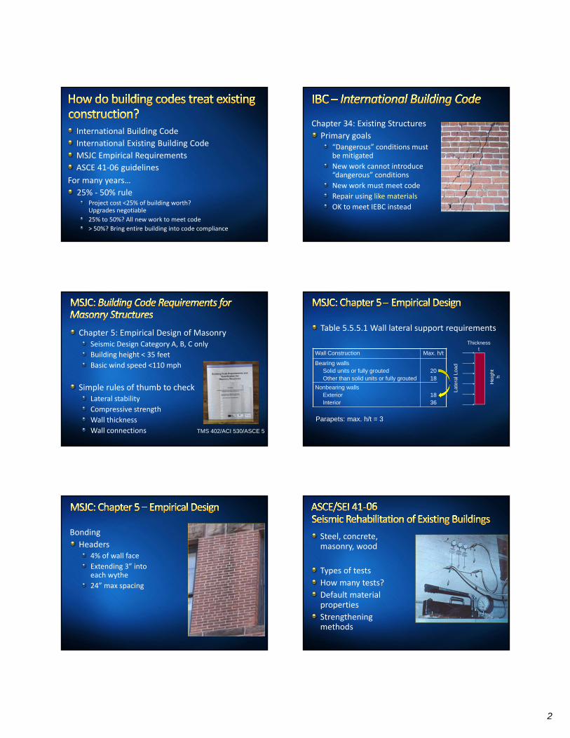
Table 5.5.5.1 Wall lateral support requirements
Thicknesst
Hei
ght
h
Late
ral L
oad
Wall Construction Max. h/t
Bearing wallsSolid units or fully groutedOther than solid units or fully grouted
2018
Nonbearing wallsExteriorInterior
1836
Parapets: max. h/t = 3
Bonding
Headers4% of wall face
Extending 3” into each wythe
24” max spacing
Steel, concrete, masonry, wood
Types of tests
How many tests?
Default material properties
Strengthening methods
3
Bearing – Stress Concentrations (f′m)
Out‐of‐Plane Flexure (Tension)
Shear Capacity
Post‐Installed Anchors General
Compressive Strength
Shear Strength
Flexural Bond
Anchors & Other
What information is needed?
As‐built configuration
Current condition
Material CharacterizationType
Engineering Properties
Visual
Ground Penetrating Radar
Pulse velocity
Impact‐echo
Tomographic imaging
Sounding
Infrared thermography
X‐ray
Metal location
Borescope
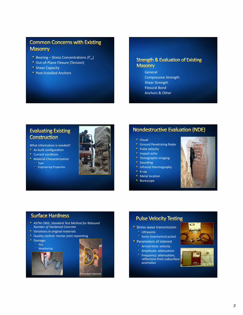
ASTM C805, Standard Test Method for Rebound Number of Hardened Concrete
Variations in original materials
Quality control: mortar joint repointing
Damage:Fire
Weathering
Pendulum Hammer
Stress wave transmissionUltrasonic
Sonic (mechanical pulse)
Parameters of interestArrival time: velocity
Amplitude: attenuation
Frequency: attenuation, reflections from subsurfaceanomalies
4
BLIND HEADERCOURSE
CRACKED HEADER
VOID COLLARJOINTS
Concrete: ASTM D 4580, Practice for Measuring Delaminations in Concrete Bridge Decks by Sounding
Chain drag, hammer
Sounding
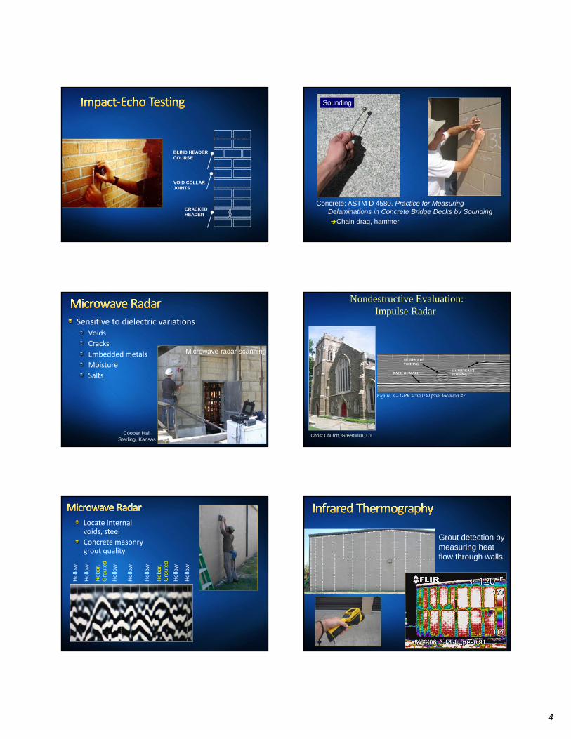
Sensitive to dielectric variations Voids
Cracks
Embedded metals
Moisture
Salts
Microwave radar scanning
Cooper HallSterling, Kansas
Nondestructive Evaluation: Impulse Radar
BACK OF WALLSIGNIFICANTVOIDING
Figure 3 – GPR scan 030 from location #7
MODERATE VOIDING
Christ Church, Greenwich, CT
Locate internal voids, steel
Concrete masonrygrout quality
Hol
low
Hol
low
Hol
low
Hol
low
Hol
low
Hol
low
Reb
ar,
Gro
uted
Reb
ar,
Gro
uted
Hol
low
Grout detection by measuring heat flow through walls
5
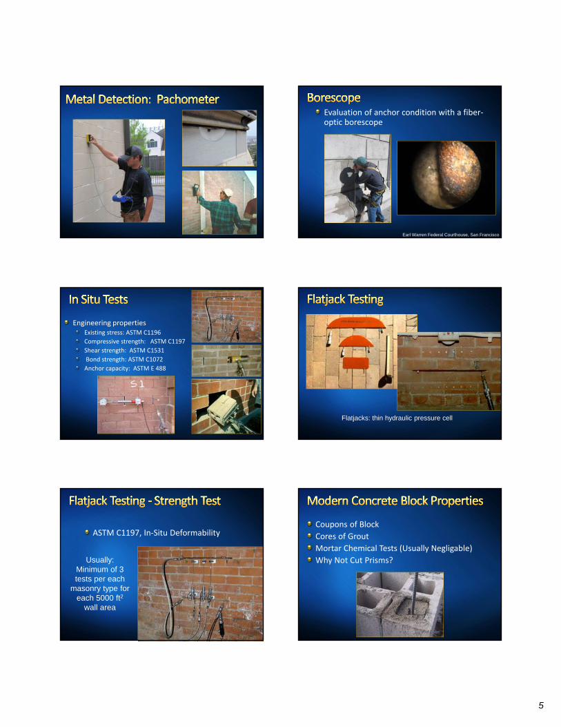
Evaluation of anchor condition with a fiber‐optic borescope
Earl Warren Federal Courthouse, San Francisco
Engineering propertiesExisting stress: ASTM C1196
Compressive strength: ASTM C1197
Shear strength: ASTM C1531
Bond strength: ASTM C1072
Anchor capacity: ASTM E 488
Flatjacks: thin hydraulic pressure cell
ASTM C1197, In‐Situ Deformability
Usually: Minimum of 3 tests per each
masonry type for each 5000 ft2
wall area
Coupons of Block
Cores of Grout
Mortar Chemical Tests (Usually Negligable)
Why Not Cut Prisms?
6
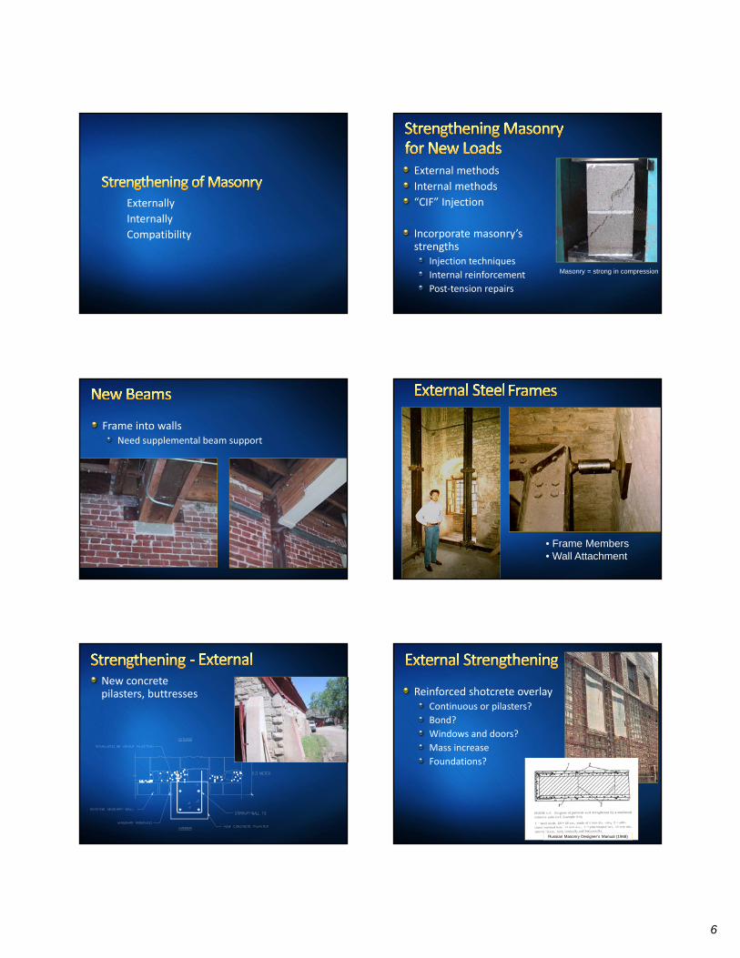
Externally
Internally
Compatibility
External methods
Internal methods
“CIF” Injection
Incorporate masonry’s strengths
Injection techniques
Internal reinforcement
Post‐tension repairs
Masonry = strong in compression
Frame into wallsNeed supplemental beam support
• Frame Members• Wall Attachment
New concrete pilasters, buttresses Reinforced shotcrete overlay
Continuous or pilasters?
Bond?
Windows and doors?
Mass increase
Foundations?
Russian Masonry Designer’s Manual (1968)
7
External ApproachesReversible
Cost effective
but
Visible
Disruptive and Space‐Consuming
Internal ApproachesAppearance not affected
but
Not easily reversible
Often more expensive
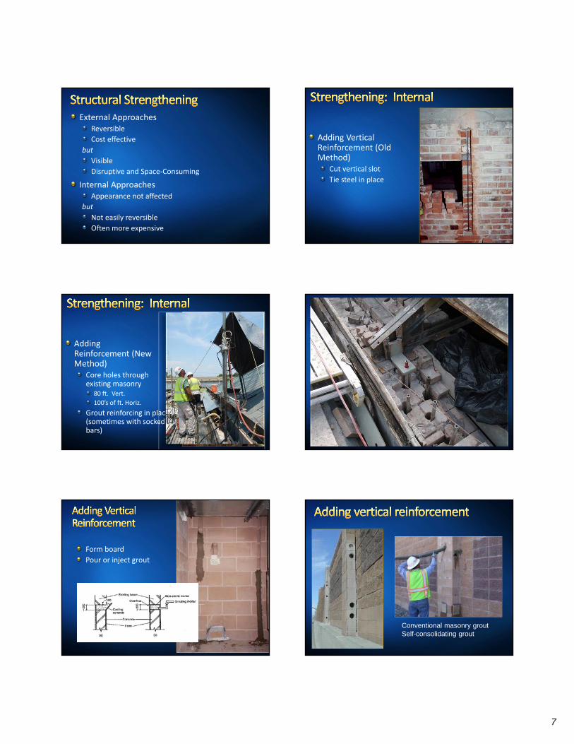
Adding VerticalReinforcement (Old Method)
Cut vertical slot
Tie steel in place
AddingReinforcement (New Method)
Core holes through existing masonry
80 ft. Vert.
100’s of ft. Horiz.
Grout reinforcing in place (sometimes with socked bars)
Form board
Pour or inject grout
Conventional masonry groutSelf-consolidating grout
8
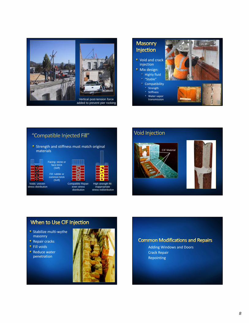
Vertical post-tension forceadded to prevent pier rocking
Void and crack injection
Mix design:Highly fluid
“Stable”
CompatibilityStrength
Stiffness
Water vapor transmission
Strength and stiffness must match original materials
Facing: stone or face brick
(Stiff)
Fill: rubble or common brick
(Soft)
Compatible Repair:even stressdistribution
Voids: uneven stress distribution
High strength fill: inappropriate
stress redistribution
CIF Material
Stabilize multi‐wythe masonry
Repair cracks
Fill voids
Reduce water penetration
Adding Windows and Doors
Crack Repair
Repointing
9
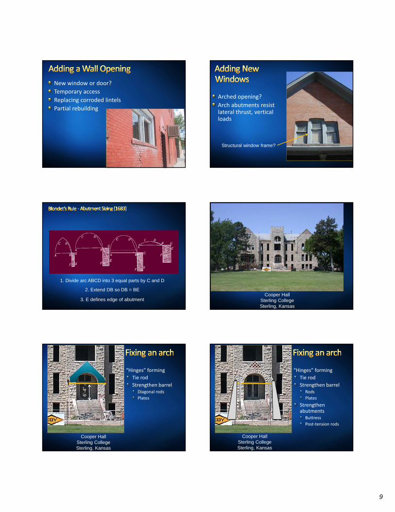
New window or door?
Temporary access
Replacing corroded lintels
Partial rebuilding
Arched opening?
Arch abutments resist lateral thrust, vertical loads
Structural window frame?
1. Divide arc ABCD into 3 equal parts by C and D
2. Extend DB so DB = BE
3. E defines edge of abutmentCooper Hall
Sterling CollegeSterling, Kansas
Cooper HallSterling CollegeSterling, Kansas
“Hinges” forming
Tie rod
Strengthen barrelDiagonal rods
Plates
6’-4
”
Cooper HallSterling CollegeSterling, Kansas
“Hinges” forming
Tie rod
Strengthen barrelRods
Plates
Strengthen abutments
Buttress
Post‐tension rods
10
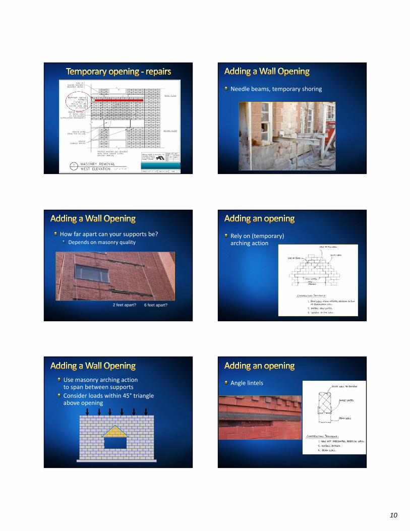
Needle beams, temporary shoring
How far apart can your supports be?Depends on masonry quality
2 feet apart? 6 feet apart?
Rely on (temporary)arching action
Use masonry arching action to span between supports
Consider loads within 45° triangle above opening
Angle lintels
11
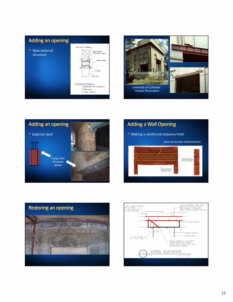
New externalstructure
University of Colorado Theatre Renovation
External steel
Hang from structure
above
Making a reinforced masonry lintel
New horizontal reinforcement
12
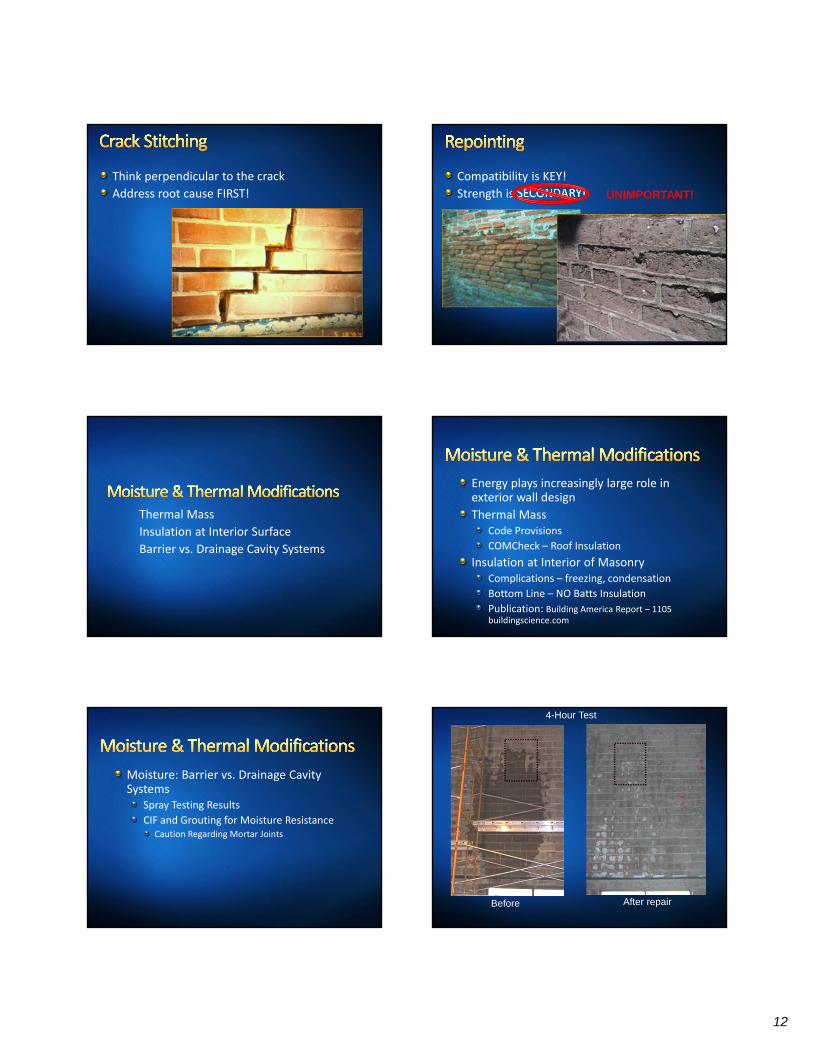
Think perpendicular to the crack
Address root cause FIRST!
Compatibility is KEY!
Strength is SECONDARY! UNIMPORTANT!
Thermal Mass
Insulation at Interior Surface
Barrier vs. Drainage Cavity Systems
Energy plays increasingly large role in exterior wall design
Thermal MassCode Provisions
COMCheck – Roof Insulation
Insulation at Interior of MasonryComplications – freezing, condensation
Bottom Line – NO Batts Insulation
Publication: Building America Report – 1105 buildingscience.com
Moisture: Barrier vs. Drainage Cavity Systems
Spray Testing Results
CIF and Grouting for Moisture ResistanceCaution Regarding Mortar Joints
4-Hour Test
Before After repair
13
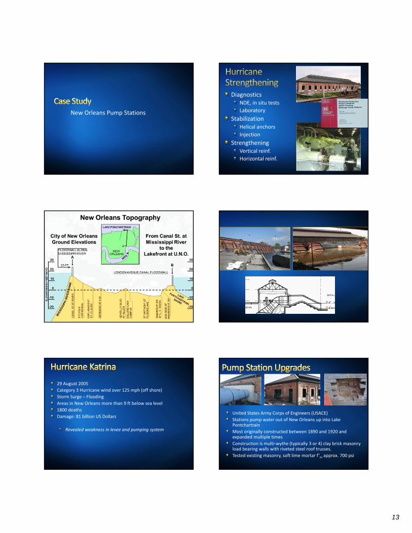
New Orleans Pump Stations
DiagnosticsNDE, in situ tests
Laboratory
StabilizationHelical anchors
Injection
StrengtheningVertical reinf.
Horizontal reinf.
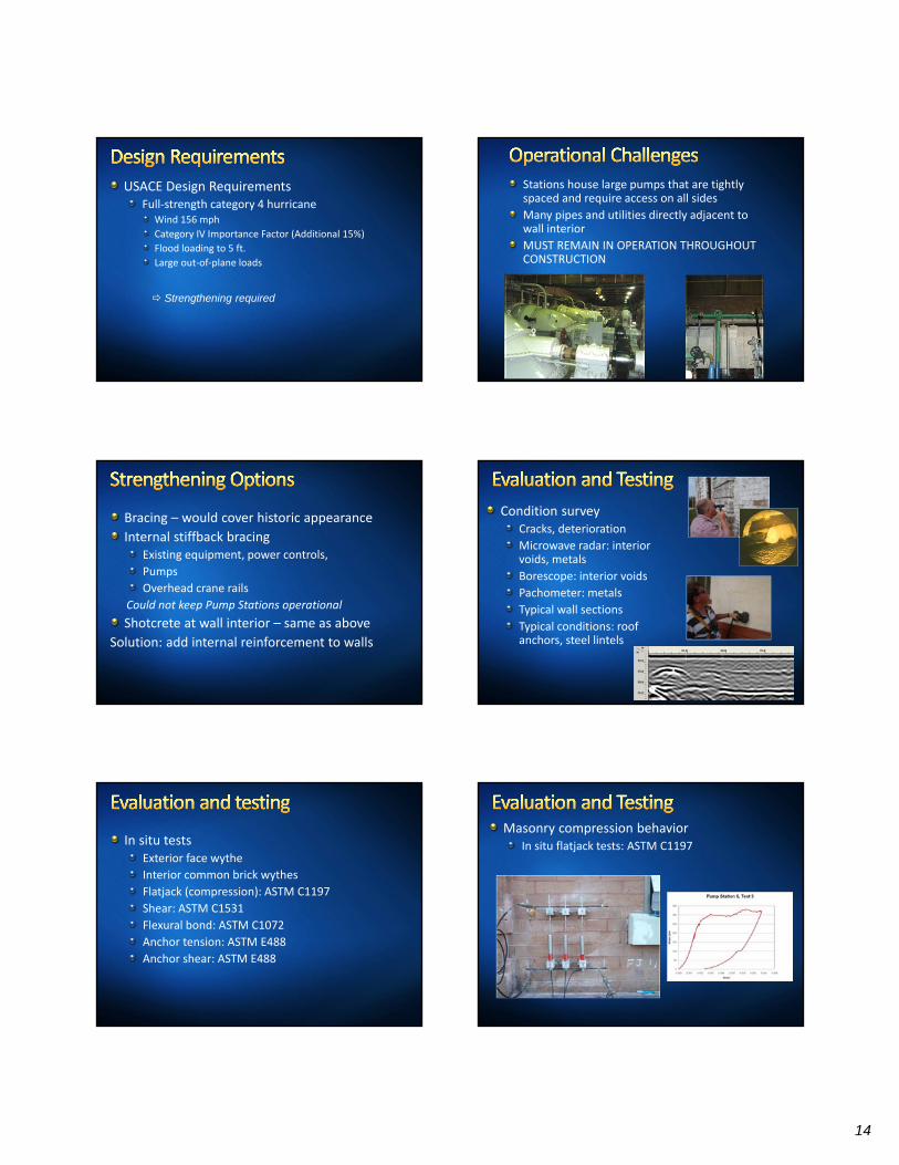
29 August 2005
Category 3 Hurricane wind over 125 mph (off shore)
Storm Surge – Flooding
Areas in New Orleans more than 9 ft below sea level
1800 deaths
Damage: 81 billion US Dollars
Revealed weakness in levee and pumping system
United States Army Corps of Engineers (USACE)
Stations pump water out of New Orleans up into Lake Pontchartrain
Most originally constructed between 1890 and 1920 and expanded multiple times
Construction is multi‐wythe (typically 3 or 4) clay brick masonry load bearing walls with riveted steel roof trusses.
Tested existing masonry, soft lime mortar f’m approx. 700 psi
14
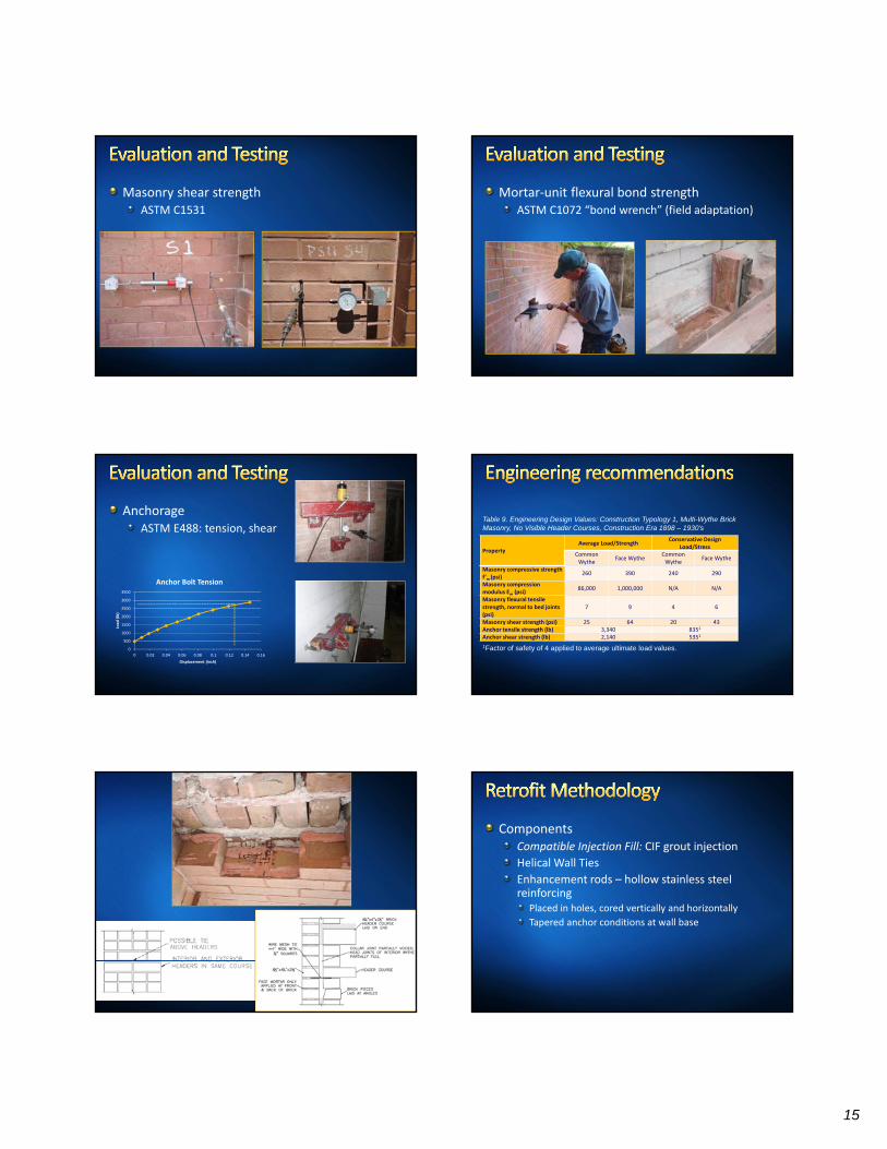
USACE Design RequirementsFull‐strength category 4 hurricane
Wind 156 mph
Category IV Importance Factor (Additional 15%)
Flood loading to 5 ft.
Large out‐of‐plane loads
Strengthening required
Stations house large pumps that are tightly spaced and require access on all sides
Many pipes and utilities directly adjacent to wall interior
MUST REMAIN IN OPERATION THROUGHOUT CONSTRUCTION
Bracing – would cover historic appearance
Internal stiffback bracingExisting equipment, power controls,
Pumps
Overhead crane rails
Could not keep Pump Stations operational
Shotcrete at wall interior – same as above
Solution: add internal reinforcement to walls
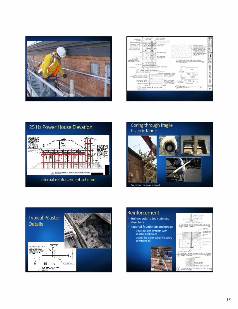
Condition surveyCracks, deterioration
Microwave radar: interior voids, metals
Borescope: interior voids
Pachometer: metals
Typical wall sections
Typical conditions: roof anchors, steel lintels
In situ testsExterior face wythe
Interior common brick wythes
Flatjack (compression): ASTM C1197
Shear: ASTM C1531
Flexural bond: ASTM C1072
Anchor tension: ASTM E488
Anchor shear: ASTM E488
Masonry compression behaviorIn situ flatjack tests: ASTM C1197
15
Masonry shear strengthASTM C1531
Mortar‐unit flexural bond strengthASTM C1072 “bond wrench” (field adaptation)
AnchorageASTM E488: tension, shear
0
500
1000
1500
2000
2500
3000
3500
0 0.02 0.04 0.06 0.08 0.1 0.12 0.14 0.16
Load
(lb)
Displacement (inch)
Anchor Bolt Tension
PropertyAverage Load/Strength
Conservative Design Load/Stress
Common Wythe
Face WytheCommon Wythe
Face Wythe
Masonry compressive strength f’m (psi)
260 390 240 290
Masonry compression modulus Em (psi)
86,000 1,000,000 N/A N/A
Masonry flexural tensile strength, normal to bed joints (psi)
7 9 4 6
Masonry shear strength (psi) 25 64 20 43Anchor tensile strength (lb) 3,340 8351
Anchor shear strength (lb) 2,140 5351
Table 9. Engineering Design Values: Construction Typology 1, Multi-Wythe Brick Masonry, No Visible Header Courses, Construction Era 1898 – 1930’s
1Factor of safety of 4 applied to average ultimate load values.
ComponentsCompatible Injection Fill: CIF grout injection
Helical Wall Ties
Enhancement rods – hollow stainless steel reinforcing
Placed in holes, cored vertically and horizontally
Tapered anchor conditions at wall base
16
91
Dry coring – no water involved
Hollow, cold‐rolled stainless steel bars
Tapered foundation anchorageDevelops bar strength with shorter anchorage
Useful for older, weak masonry construction
17
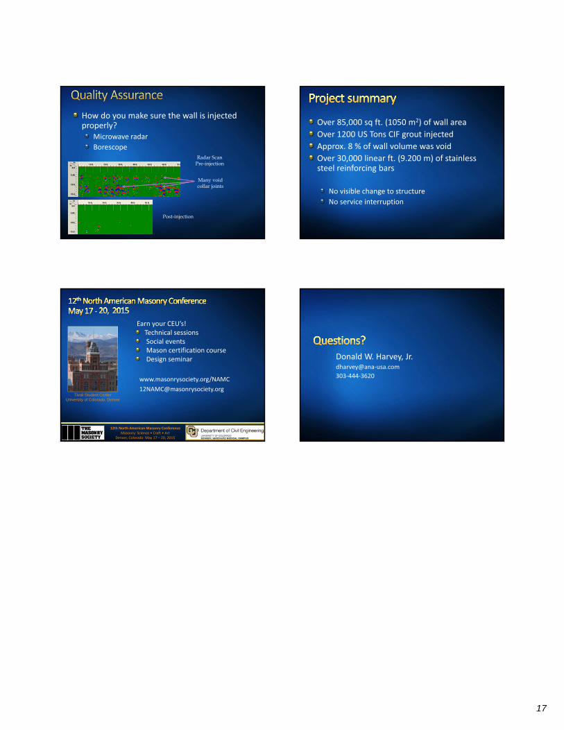
How do you make sure the wall is injected properly?
Microwave radar
Borescope Radar Scan
Pre-injection
Post-injection
Many void collar joints
Over 85,000 sq ft. (1050 m2) of wall area
Over 1200 US Tons CIF grout injected
Approx. 8 % of wall volume was void
Over 30,000 linear ft. (9.200 m) of stainless steel reinforcing bars
No visible change to structure
No service interruption
Earn your CEU’s! Technical sessionsSocial eventsMason certification courseDesign seminar
12th North American Masonry ConferenceMasonry: Science • Craft • Art
Denver, Colorado May 17 – 20, 2015
Tivoli Student CenterUniversity of Colorado, Denver
www.masonrysociety.org/NAMC
Donald W. Harvey, Jr.dharvey@ana‐usa.com
303‐444‐3620

Notes: