Anger Camera for neutrons
32
Anger Camera for neutrons F. A. F. Fraga, L. M. S. Margato ,S. T. G. Fetal, M. M. F. R. Fraga, A. Morozov, L. Pereira, R. Ferreira Marques, P. Mendes, J. P. Rodrigues LIP Coimbra, Universidade de Coimbra
-
Upload
vaughan-johns -
Category
Documents
-
view
29 -
download
0
description
Anger Camera for neutrons. F. A. F. Fraga, L. M. S. Margato ,S. T. G. Fetal, M. M. F. R. Fraga, A. Morozov, L. Pereira, R. Ferreira Marques, P. Mendes, J. P. Rodrigues LIP Coimbra, Universidade de Coimbra. FP6 NMI3 JRA2 RII3-CT-2003-505925 ended 2008. - PowerPoint PPT Presentation
Transcript of Anger Camera for neutrons

Anger Camera for neutrons
F. A. F. Fraga, L. M. S. Margato ,S. T. G. Fetal, M. M. F. R. Fraga, A. Morozov, L. Pereira, R. Ferreira Marques, P. Mendes, J. P. Rodrigues
LIP Coimbra, Universidade de Coimbra

FP6 NMI3 JRA2 RII3-CT-2003-505925 ended 2008
MILAND – development of thermal neutron detectors•Would increase knowledge about neutron detectors, but should have a deliverable working detector prototype with a firm and clear specification
• Partners and Observers• P1 CCLRC N. Rhodes (UK) T3, T6, T7• P2 GKSS R. Kampmann (Germany) T1, T4, T5, T6, T7• P3 BNC L. Rosta (Hungary) T1, T5, T6, T7• P4 ILL B. Guerard (France) T1, T2, T3, T4, T5, T6, T7 coordinator• P5 LLB C. Fermon (France) T2, T4, T6, T7• P6 FRM-II K. Zeitelhack (Germany) T1, T2, T4, T6, T7• P7 LIP F. Fraga (Portugal) T2, T3, T6, T7
ObserversEFO1 BNL G. Smith (USA)
• EFO2 SNSR. Cooper (USA) • EFO3 TU H. Takahashi (Japan) • EFO4 RAL J. Mir (UK)• EFO5 BNL R. Krueger TU Delft (NL)
•32 x 32 cm2 detector•1 mm resolution (FWHM) res/length = 3x10⁻⁴
•1 MHz global count rate•100 kHz / mm2 local (peak) count rate•Gamma background rejection 10-8
•50% efficient at 1.8Å•parallax free•Cost is critical
Integrated Infrastructure Initiative for Neutron Scattering and Muon Spectroscopy

Neutron Detectors nuclear reactions to convert neutrons
• n + 3He 3H + 1H + 0.764 MeV Gaseous detectors (CF4, prop.)
• n + 6Li 4He + 3H + 4.79 MeV Scintillators• n + 10B 7Li* + 4He7Li + 4He + 0.48 MeV +2.3 MeV
(93%) 7Li + 4He +2.8 MeV ( 7%)
• n + 155Gd Gd* -ray spectrum conversion electron spectrum • n + 157Gd Gd* -ray spectrum conversion electron spectrum • n + 235U fission fragments + ~160 MeV • n + 239Pu fission fragments + ~160 MeV


Scintillators for Neutron Detectors
CWE van Eijk, NIM A529(2004)260-267

Gaseous detectors
n + 3He 3H + 1H + 0.764 MeV
CF4 should be added to control the range -3 bar for 1mm FWHM
• CF4 is a good scintillator, but only a few primary photons• Secondary scintillation ~.3 photon per secondary electron
200 300 400 500 600 700 800 9000
200
400
600
800
I norm (a
.u.)
(nm)
CF3
*
CF4+*, CF3
+*

PMT 2
10mm
35m
m
Boron Mask
Neutron Beam
Quartz Window
anodes
PMT 3
AQUISISITION CARDS: Acqiris, CC103
PMT 1 PMT 4
PC
trigger (from anodes or cathodes)
Drift electrode
n
T
p

Scintillation Anger camera
PMT
Transparent window
MSGC
PMT base
gas
Neutron window
PMT
PMT base

New MSGC Batch
NMI3 Meeting, CORSICA, 25-28th June 2008
Remarks
• Cathodes width of the new set of microstrips is more or less half of the older ones (181m vs. 398 m) and the anodes seems to be larger.
• To achieve the same charge gain the new microstrip needed a higher anode voltage than the older one.
• For instance, at 1 bar of CF4, to reach a gain of G ~103 we should apply a voltage of Va~1900V, something like 840V more than in the older microstrip (Va=1060V).
• Taking off the drawbacks linked to a higher voltage, the light yield obtained with the new microstrip (for G ~103 ) is ~ 0.263 ph/sec-e, about 4.5 times higher than the light yield in the older one (~0.045 ph/sec-e).
• This MSGCs batch are unable to operate above 1 bar CF4 (discharges).

Charge gain and light/charge versus anode voltage 15, 20 and 30µm anodes
CF4 (1bar)
CF 4 (1bar)
1.0E+01
1.0E+02
1.0E+03
1.0E+04
500 700 900 1100 1300 1500
Va (V)
Gai
n
15 micron anodes20 micron anodes30 micron anodes
CF 4 (1bar)
0
5
10
15
20
500 700 900 1100 1300 1500
Va (V)
S PM
T /
Qan
ode
15 micron anodes
20 micron anodes
30 micron anodes

New MSGC Batch
NMI3 Meeting, CORSICA, 25-28th June 2008
Charge and light measurements
Charge gain versus anode voltage Number of emitted photons per
secondary electron
CF 4 (1bar); V d =-700V
1.0E+01
1.0E+02
1.0E+03
1.0E+04
800 1000 1200 1400 1600 1800 2000
V anode (V)
Gai
n
15 micronNew Microstrip - April 2008
CF 4 (1bar)
0.00
0.10
0.20
0.30
0.40
0.50
1.0E+02 1.0E+03 1.0E+04Gain
Em
itte
d P
hoto
ns /
s.e.
15 micron
New Microstrip - April 2008

MSGC ILL6C at High pressure
NMI3 Meeting, CORSICA, 25-28th June 2008
Measurements at 3 bar CF4
CF 4 (3bar)
0.00
0.10
0.20
0.30
0.40
0.50
1.0E+02 1.0E+03 1.0E+04Gain
Em
itte
d P
hoto
ns /
s.e
ILL6C - Nº1ILL6C - Nº2LLB - 15 micron
CF4 -3bar
1.0E+02
1.0E+03
1.0E+04
1400 1600 1800 2000V anode (V)
Gai
n
ILL6C - Nº2ILL6C - Nº3LLB - 15 micron
Charge gain versus anode voltage Number of emitted photons per
secondary electron

Simulations F.Fraga, Hamburg meeting

GSPC details

GSPC in position at the ILL beamAquisition system by Acquiris and E. Shooneveld

2D position images Vanode = 1360, 1550 1650 and 1850V

Mask_1650_3.eve: Va=1650 V; VPMT= 800 V.
fwhm (yy)~1.63 mm
fwhm (xx)~1.68 mm

Mask_1650_3.eve: Va=1650 V; VPMT= 800 V
FHWM center peak 1.68 mm
FHWM center peak 1.63 mm

FWHM resolution versus Vanode
0.00
0.50
1.00
1.50
2.00
2.50
3.00
1300 1500 1700 1900
Vanode (V)
peak
FW
HM
(m
m)
(XX)
(YY)
•For the best safe conditions (Vanode =1850 V; VPMT= 800 V) the intrinsic resolution is 1.1mm after we deconvolute the beam width

Detector uniformity (1850V)
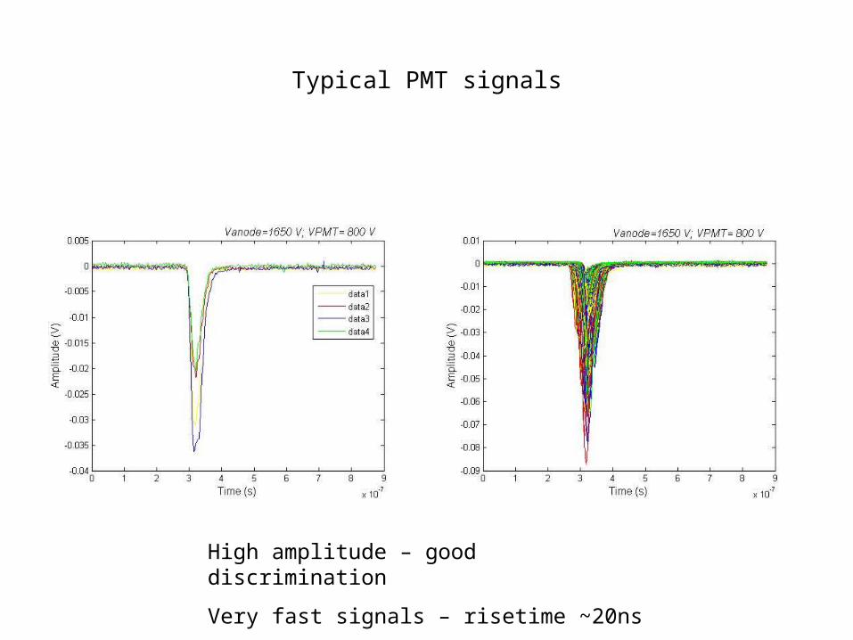
Typical PMT signals
High amplitude – good discrimination
Very fast signals – risetime ~20ns


Transparent electrode MSGC
• Manufactured at the Tokyo University and supplied by Hiroyuki Takahashi
• 90% ITO electrode transparency
• The transparent window can be the active element
• Multigrid approach proposed –it has the advantage of a very high local count rate.

ITO M - MSGC
NMI3 Meeting, CORSICA, 25-28th June 2008
Photographs

ITO M - MSGC
NMI3 Meeting, CORSICA, 25-28th June 2008
Experimental Setup
Drift length = 10 mm
Distance between microstrip and PMT = 34.8mm

ITO M - MSGC
NMI3 Meeting, CORSICA, 25-28th June 2008
Ar+5%CF4 (1atm, 100cc/min.) and CF4 (1atm, 100cc/min.)
ITO M - MSGC
1.0E+02
1.0E+03
1.0E+04
1.0E+05
500 700 900 1100V anode (V)
Gai
n
Ar+5%CF4 (Vg1=400V)
100%CF4 (Vg1=600V)
ITO - Microstrip
0.00
0.10
0.20
0.30
0.40
1.0E+02 1.0E+03 1.0E+04Gain
Nº o
f em
itte
d ph
oton
s / s
.e Ar+5%CF4 (Vg1=400V)
100%CF4 (Vg1=600V)
Charge gain versus anode voltage Number of emitted photons per
secondary electron

ITO M - MSGC
NMI3 Meeting, CORSICA, 25-28th June 2008
Effect of GRID potential (Vg) on Gain and light yield
ITO M - MSGC: 100%CF 4 , Vd=-500V
1.0E+02
1.0E+03
1.0E+04
1.0E+05
600 800 1000 1200V anode (V)
Gai
n
Vg1=200V
Vg1=400V
Vg1=600V
vg1=800V
ITO - Microstrip: 100%CF 4 , Vd=-500V
0.00
0.10
0.20
0.30
0.40
1.0E+02 1.0E+03 1.0E+04 1.0E+05
GainN
º of e
mit
ted
phot
ons
/ s.e Vg1=200V
Vg1=400V
Vg1=600V
Vg1=800V
Charge gain versus anode voltage for several GRID voltages
Number of emitted photons per secondary electron

ITO M - MSGC
NMI3 Meeting, CORSICA, 25-28th June 2008
Example of typical signal taken directly from the PMT Hamamatsu R1387 (RL=50 ): 55Fe (5.9keV) X-ray source
•100%CF4 (1atm)
•Vdrift= -500V, Vcathode=0
•Vanode=990V Vg1= 600V
•VPMT=-1000V
60ns
100 mV

MSGC ILL6C at High pressure
NMI3 Meeting, CORSICA, 25-28th June 2008
Measurements at 3, 4 and 5 bar CF4
CF4 - 3, 4 & 5 bar
1.0E+02
1.0E+03
1.0E+04
1400 1900 2400 2900V anode (V)
Gai
n
LLB - 15mic.-3 bar ILL6C - 3 barILL6C - 4 barILL6C - 5 bar
CF 4 - 3, 4 & 5 bar
0.00
0.10
0.20
0.30
0.40
0.50
1.0E+02 1.0E+03 1.0E+04Gain
Em
itte
d P
hoto
ns /
s.e
LLB - 15mic. - 3barILL6C - 3 barILL6C - 4 barILL6C - 5 bar
Charge gain versus anode voltage Number of emitted photons per
secondary electron

2009-2011 FP7 WP22CP-CSA_INFRA-2008-1.1.1 Number 226507-NMI3
• Development of new thermal neutron detector technologies based on Gaseous Scintillation Proportional Counters (GSPC) • Explore their potential to overcome the limitations in light output and rate capability of existing scintillation detectors • Investigate their potential as high resolution detectors for Reflectometry or time resolved SANS. • Built and study small scalable prototypes
http://detectors.neutron-eu.net/Detectors

The new family members, born in Munich two months ago!
We will go on studying the scintillation and the PMT readout

The good not so good new
• European Spallation Source (ESS) went to Lund in Sweden
The bad new
• 3He crisis