Anemometer Manual v2
20
Davis Cup Anemometer Installation Guide Version 2
-
Upload
decagon-devices -
Category
Documents
-
view
216 -
download
1
description
Anemometer manual v2
Transcript of Anemometer Manual v2

Davis Cup Anemometer
Installation Guide
Version 2

Decagon Devices, Inc. 2365 NE Hopkins Court
Pullman, WA 99163
(509) 332-2756
www.decagon.com [email protected]
© 2009 Decagon Devices, Inc. All rights reserved.

Contents INTRODUCTION ........................................... 1
System And Hardware Compatibility ................ 1
How the Davis Cup Anemometer works
with the Em50 Logger................................. 1
COMPONENTS AND HARDWARE ................... 2
Hardware Kit:.................................................... 3
Tools and Materials Needed............................. 3
ASSEMBLING THE ANEMOMETER ................. 4
Attaching the Wind Cups.................................. 4
Testing the Anemometer .................................. 5
INSTALLING THE ANEMOMETER ................... 6
Choosing the Best Location.............................. 6
Mounting the Anemometer ............................... 6
MAINTENANCE ......................................... 11
TROUBLESHOOTING.................................. 12
CUSTOMER SUPPORT ............................... 14
SPECIFICATIONS....................................... 15

1
Introduction The anemometer enables you to measure and display wind-related conditions such as wind speed and wind direction with your Em50 or Em50R logger.
System And Hardware Compatibility Em50 Firmware version 1.19 or greater
ECH2O Utility 1.11 or greater
ECH2O Utility Mobile 1.18 or greater
How the Davis Cup Anemometer works with the Em50 Logger
Direction:
The Em50 measures the average wind direction in one minute intervals. The value of the wind direction and number of pulse counts (magnitude) are used to resolve the wind direction into X and Y vector components. The vector components from multiple one-minute readings are summed together. The X and Y components are combined to store the “dominant” or “weighted average” wind direction for the measurement interval.
NOTE: When there is no wind, the vector math for direction will resolve to zero (North) — regardless of the actual direction of the wind vain.
2
Speed:
The Em50 integrates wind speed pulses for one minute. The highest one-minute count in each measurement interval becomes the value for the gusts data. The average of the one-minute counts becomes the average speed for each measurement interval.
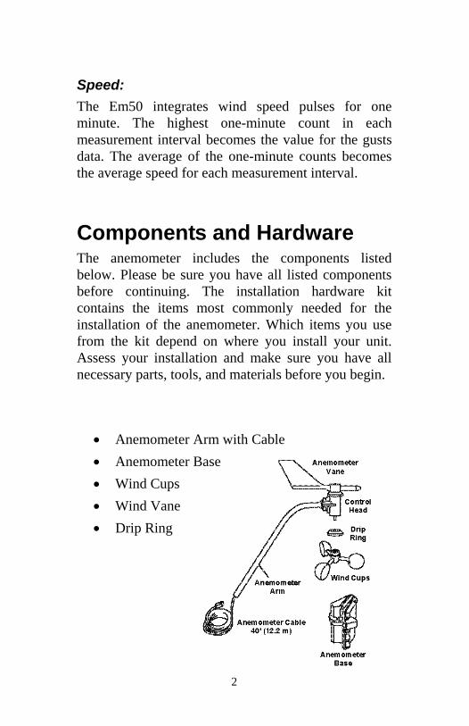
Components and Hardware The anemometer includes the components listed below. Please be sure you have all listed components before continuing. The installation hardware kit contains the items most commonly needed for the installation of the anemometer. Which items you use from the kit depend on where you install your unit. Assess your installation and make sure you have all necessary parts, tools, and materials before you begin.
Anemometer Arm with Cable
Anemometer Base
Wind Cups
Wind Vane
Drip Ring

3
Hardware Kit:
You may need to adapt or purchase additional hardware to fit your individual requirements.
Two U-Bolts
Four ¼” Flat washers
Four ¼” Hex Nuts
Four ¼” x 3” Lag Screws
One #4-40 x 1 ¼” Pan Head Screw
One #4 Flat Washer
One #9 Lock Washer
One #4-40 Hex Nut
0.05” Allen Wrench
Note: If any of the hardware components are missing, contact Decagon Devices about receiving replacement hardware or other components.
Tools and Materials Needed You will need the following tools and materials to install your anemometer:
Cable Clips or Weather-Resistant Cable Ties
Make sure the clips or ties you use to secure the anemometer cable have screw holes or other means for mounting the cable. Do not use metal staples to secure the cables.
Stainless Steel Hose Clamps

4
Small Screwdrivers
Adjustable Wrench
Hand-Held Compass or Local Area Map
Assembling the Anemometer
Attaching the Wind Cups 1. Before installing the anemometer, attach the wind
cups.
2. Push the wind cups onto the smaller of the two stainless steel shafts .
3. Slide the wind cups as far up the shaft as possible.
4. Use the Allen wrench provided to tighten the set screw on the side of the wind cups to approximately finger tight.
5. Spin the wind cups. If they do not spin freely, loosen the set screw, lower the cups slightly, then retighten the set screw.

5
6. Repeat Step 4 until the wind cups spin freely.
Note: The wind vane installation is affected by the direction of the mounting arm. Wind vane direction will be modified during the anemometer installation.
Testing the Anemometer Before beginning your installation, follow the instructions below to test the anemometer wind speed and wind direction functionality. You will need ECH2O Utility or ECH2O Utility Mobile connected to an Em50 logger.
1. Connect anemometer cable to a port in a Em50 logger.
2. In the sensor pull-down menu for the chosen port in ECH2O Utility, pick “Davis Cup Anemometer”
3. Enter your measurement interval.
4. Spin the wind cups.
5. Scan ports of the logger with ECH2O Utility. You should see revolutions and direction.
6. Note the direction reading of the anemometer.
7. Grab the wind vane and twist about half a turn.
8. Scan ports, reading should have changed about 180 degrees.
9. Disconnect the cables when you are finished testing the anemometer.

6
Installing The Anemometer
Choosing the Best Location Use the following guidelines to determine the best location for your anemometer.
Install the anemometer in a location where wind flow is unobstructed by trees and nearby buildings.
For the most accurate readings, the anemometer should be mounted at least 4 feet (1.2 m) above any obstructions.
You may do this by mounting the anemometer on a television antenna mast, a wooden post, or a metal pipe.
Mounting the Anemometer Use the following procedures to mount the anemometer:
Checking the Base Orientation
You will need to know which way to orient the base before installing it.
1. Insert the anemometer arm into the base
2. Push the #4-40 x 1 ¼” pan head screw through the holes in the arm and the base as described in “Attaching the Wind Vane” on page 9.

7
3. If the screw does not slide easily through the holes, rotate the base 180° to line up the opposite holes, then try again.
4. Note the correct base orientation for use when you install the base later in the installation process.
Installing the Base on a Wooden Post or Surface
1. Hold the anemometer base against the wood surface and use a pencil to mark the location of the four holes on the base.
2. Use a drill with a 3/16” (5-mm) drill bit to make pilot holes in these locations.
3. Drive the lag screws through the holes in the anemometer base and into the wood.
Installing on Antenna Mast or Metal Pipe
1. On an antenna mast or pipe with outside diameter of 7/8” to 1 1/4” (22 to 32 mm):
2. Hold the anemometer base against the pipe and insert the two U-bolts through the back of the base so that the U-bolts wrap around the pipe.
3. Place a 1/4” washer and a 1/4-20 hex nut over each end of the

8
U-bolts and use a wrench to tighten the hex nuts.
Installing the Base on a Metal Mast or Pipe: Outside Diameter Greater than 1¼ in. (32mm)
1. Use two stainless steel hose clamps to attach the mounting base to masts or pipes larger than 1 1/4” diameter, large enough to fit around the mast or pipe and the anemometer base. You may purchase hose clamps at your local hardware store.
2. Hold the anemometer base against the pipe and fasten the hose clamps over the anemometer base and around the metal mast or pipe.
Attaching Arm to Base
1. Insert the anemometer arm into the anemometer base.
2. Guide the anemometer cable through the slot as you insert the arm.
3. Insert the pan head screw into one of the holes in the base and slide it through the arm.
4. Secure the pan head screw using the flat washer, lock washer, and hex nut as shown.

9
Attaching the Wind Vane
To mount the wind vane, look at the ECH2O Utility “scan” option display to orient the vane accurately.
1. Connect the anemometer cable to the Em50 or Em50R and remove the wind vane attachment using the included Allen wrench.
2. Press SCAN in ECH2O Utility or ECH2O Utility Mobile to display wind direction in degrees.
3. Use a compass or map to determine true north.
4. Slowly turn the wind direction shaft with your fingers. Stop turning when the weather station display reaches 0 degrees.
5. Being careful to keep the stainless steel shaft from turning, place the wind vane on the shaft with the bullet-shaped nose of the vane pointing to true north.
6. Slide the wind vane down onto the shaft as far as it will go.
7. Use the Allen wrench provided to tighten the set screw on the side of the wind vane.

10
8. Test your assembly by pointing the wind vane in any direction and (using the compass or map as a guide) making sure the ECH2O Utility “Scan” displays the correct wind direction. Readjust the vane if necessary.
9. Spin the wind cups to make sure you get a wind speed reading. Readjust the cups if necessary.
10. Secure the cable to the metal mast or pipe with electrical tape. Secure the rest of the cable according to the directions below.
11
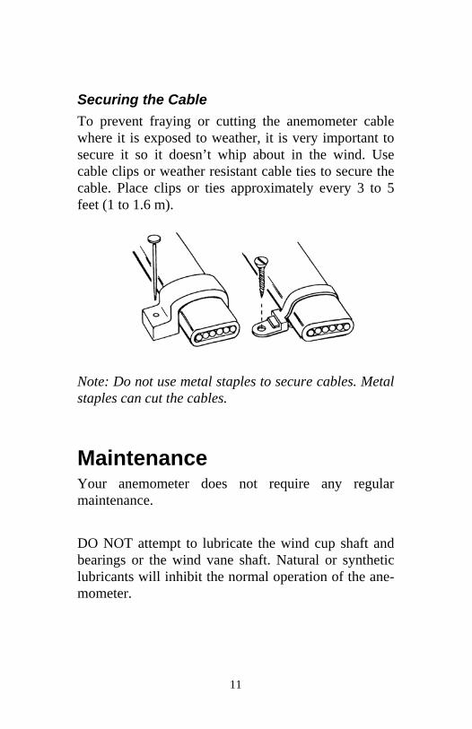
Securing the Cable
To prevent fraying or cutting the anemometer cable where it is exposed to weather, it is very important to secure it so it doesn’t whip about in the wind. Use cable clips or weather resistant cable ties to secure the cable. Place clips or ties approximately every 3 to 5 feet (1 to 1.6 m).
Note: Do not use metal staples to secure cables. Metal staples can cut the cables.
Maintenance Your anemometer does not require any regular maintenance.
DO NOT attempt to lubricate the wind cup shaft and bearings or the wind vane shaft. Natural or synthetic lubricants will inhibit the normal operation of the ane-mometer.

12
Troubleshooting While your anemometer is designed to provide years of trouble-free operation, occasionally problems may arise. If you are having a problem with your unit, please check the following troubleshooting procedures before sending the unit in for repair. You will be able to solve many of the problems yourself. If, after checking these procedures you are unable to solve the problem, please call Decagon Devices for further instructions (see next section on “Customer Support”) Please do not return your unit for repair without receiving prior authorization from Decagon Devices.
Problem 1:
Wind speed reads 0 all the time or wind direction is showing “ * * * ” in data field.
Solutions:
Make sure anemometer is plugged into port on Em50 or Em50R.
Check for broken wire along length of anemometer cable. Carefully check areas where the cable has been secured.
Try dropping the wind cups approximately 1/16” to 1/8” (1.5 to 3 mm) lower on the mounting shaft. Use the included Allen wrench to loosen and retighten the wind cup assembly.
If you still do not get a reading, the problem is with the anemometer. Contact Decagon Devices for return authorization.

13
Problem 2:
Wind speed reading seems too high or low.
Solutions:
Check installation by spinning wind cups. If the wind cups spin freely and the weather station displays a wind speed, the wind cups are installed correctly. If the wind cups don’t spin freely, then try dropping the wind cups approximately 1/16” to 1/8” (1.5 to 3 mm).
Check for any obstructions blocking the wind near the anemometer.
Problem 3:
The wind direction data always reports 0 (North) whenever the wind speed is zero, even if the wind vain is pointing a different direction.
Solutions:
The Em50 uses wind speed and direction to calculate the dominant wind direction (see page one: How the Davis Cup Anemometer works with the Em50 Logger). Because this calculation uses vector math, reported wind direction is zero when there is no wind speed.

14
Customer Support If you ever need assistance with your Anemometer, or if you just have questions or feedback, there are several ways to contact us.
Note: If you purchased your Anemometer through a distributor, please contact them for assistance.
Phone
(800) 755-2751 – USA and Canada Only
(800) 332-2756 – International
Our Customer Support and Sales Representatives are available Monday thru Friday, 8:00am–5:00pm Pacific Time.
Fax
(509) 332-5158
Note: With any correspondence, please include your name, contact information, instrument serial number(s), and a description of your problem or question.
15
Specifications
Wind Direction
1° increments
Accuracy: ± 7°
Wind Speed
Range: 2 to 129 mph, 4 to 209 kph, 1 to 58 m/s,
Accuracy: ± 5°
This product complies with the essential protection requirements of the EC EMC Directive 89/336/EC.
This anemometer has been adapted to work with Decagon Devices ECH2O System and is based on the Standard Anemometer manufactured by Davis Instruments. The technical information provided herein is provided courtesy of

Decagon Devices, Inc. 2365 NE Hopkins Court
Pullman, WA 99163
(509) 332-2756
www.decagon.com [email protected]
© 2009 Decagon Devices, Inc. All rights reserved.