
and they bothlistened to thewater, that for them was not ... · su progetto dell’architetto Carlo...
134
“…and they both listened to the water, that for them was not water at all, but the voice of life, of what exists, and of what eternally becomes.” Hermann Hesse
-
Upload
nguyenlien -
Category
Documents
-
view
213 -
download
0
Transcript of and they bothlistened to thewater, that for them was not ... · su progetto dell’architetto Carlo...

“…and they both listened to the water,
that for them was not water at all,
but the voice of life,
of what exists,
and of what eternally becomes.”
Hermann Hesse

Nel variegato panorama dei “fontanieri” Delta Enginee-ring a pieno titolo si può definire innovatrice e precursorein Italia di un trend che invece è ormai consolidatoin numerosi paesi occidentali quali Francia, Spagna,Inghilterra, Stati Uniti, ecc..L’azienda si sta infatti imponendo in questo particolaremercato, introducendo la figura di water consultant, sup-portata da un ufficio tecnico altamente specializzato,quale fondamentale elemento di sviluppo di qualsiasiprogetto riguardante un’architettura d’acqua. Dopoavere per lungo tempo coltivato una tradizione di“fontanieri “ che nel 6 -‘700 consentì la realizzazione difontane come quelle di Tivoli, Villa d’Este ecc., per varieragioni questa italica specifica abilità si era progressiva-mente spenta nel corso dell’8 -‘900.Grazie ad una rinnovata sensibilità architettonica adopera dei maggiori architetti contemporanei si è rianno-dato un filo che sembrava irrimediabilmente smarrito.Quanto era sopravvissuto di questa memoria si palesava inuna eterogenea compagine di aziende commerciali votatealla distribuzione di prodotti e alcuni artigiani che eserci-tavano con passione ma pochi mezzi la loro abilità.Quella intrapresa da Delta Engineering è una piccolarivoluzione culturale.Non più venditori o installatori di componenti, maspecialisti anzitutto nella ideazione e realizzazione deglieffetti d’acqua richiesti dai nostri clienti.Delta Engineering cerca cioè di far rivivere la cultura del-l’acqua proponendo gli standard qualitativi di eccellenzache ci appartenevano. Mediando la tradizione italiana diarte e design con le nuove tecnologie importate dagliStati Uniti è iniziata la produzione di fontane non piùmonumentali e statiche, bensì di veri e propri teatri d’ac-qua in grado di generare una interazione con il pubblicoche ne fruisce e l’ambiente in cui sono inseriti. Il primograndioso risultato di tale impegno è quanto realizzatosu progetto dell’architetto Carlo Fucini all’interno dellaReggia di Venaria Reale.Questo volume rappresenta un case history nel qualeDelta Engineering, ripercorrendo la storia di questafontana dalla genesi del progetto alla sua realizzazione,illustra i vari gradi di consulenza che è in grado di offrire.
Within the diversified scene of “fountain making” DeltaEngineering is a company that can certainly be defined asinnovating, preceding in Italy a trend which is alreadysettled in various Western countries such as France, Spain,England, United States, etc.Our company is actually imposing its presence on thispeculiar market, introducing the water consultant as a keyfigure in the development of each project concerningwater architectures. In this area also the water featurespecialist find its role, with the back up of a highlyspecialised technical office.After a long time of carrying on a tradition of "fountainmaking" which over the 16th and 17th centuries allowedthe creation of fountains such as those of Tivoli, Villad’Este, etc., for various reasons this Italian specific skill wasgradually turned off during 19th – 20th centuries.Thanks to a renewed architectural sensitivity developedby the major contemporary architects, a thread thatseemed hopelessly lost has been picked up again.What had survived of this tradition used to appear in aheterogeneous aggregate of commercial companiesaiming at the distribution of products and a fewcraftsmen who exercised their ability with passion butwithout many means.What Delta Engineering has undertaken is a smallcultural revolution.No more sellers or installers of components, but, first ofall, experts in designing and implementing the watereffects required by our customers.Delta Engineering tries to come back to the water cultureproposing the quality standards of excellence thatbelonged to us. Mediating the Italian tradition of art anddesign with new technologies imported from the USA westarted the production of real water theatres that are nomore monumental and static, but able to create aninteraction with the public that enjoys them and the en-vironment. The first great result of such commitment isthe creation of the one designed by the architect CarloFucini within the Royal Palace of Venaria RealeThis volume is a case history in which Delta Engineering,retracing the story of this fountain from the genesisof the project to its implementation, illustrates theconsulting services that is able to offer.

introductionGianfranco DeganelloC.E.O.

schematic design phase1.1. Concept Development Workshop1.2. Budgeting1.3. Servicing1.4. Preliminary Division of Responsibility Matrix1.5. Testing Recommendations1.6. General Recommendations1.7. Final Schematic Design (Sd) Presentation
design development2.1. Applications Testing2.2. General CAD Drawings2.3. Schematic Diagramming2.4. Equipment Room2.5. Components2.6. Costs2.7. Specifications
sd 01
dd 02

tender/bid documents3.1. Water Feature Documents3.2. Specifications3.3. Component List3.4. Construction Costs
construction4.1. Bid Phase Assistance4.2. Technical Review4.3. Construction Phase4.4. Water Feature Commissioning Method Statement4.5. Digging and circuits setting4.6. Grid implementation on flooring4.7. Equipment installation4.8. Programming and preliminary testing4.9. Final Testing
commissioning5.1. Choreography and programming5.2. Training5.3. Final audit5.4. Final review of all OEM manuals and as
built documentation5.5. Maintenance
td 03
cn 04
cm 05

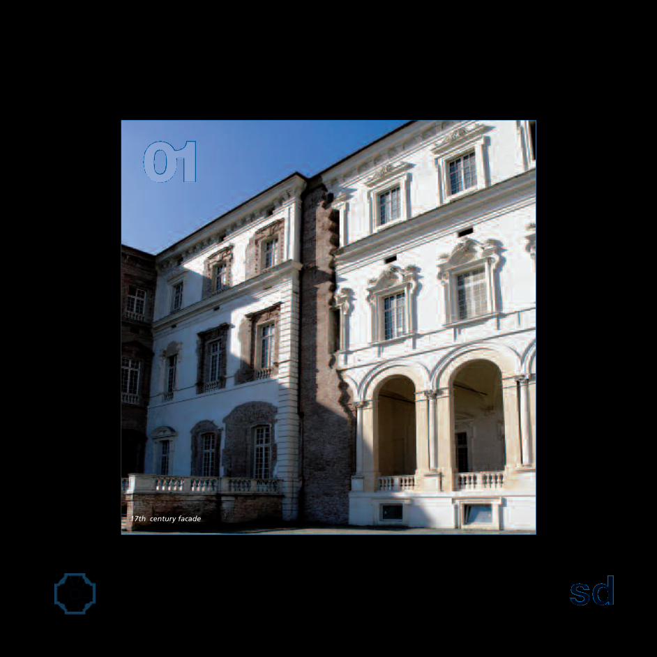
17th century facade

schematic design phase
1.1. Concept Development Workshop1.2. Budgeting1.3. Servicing1.4. Preliminary Division of Responsibility Matrix1.5. Testing Recommendations1.6. General Recommendations1.7. Final Schematic Design (Sd) Presentation

1665 - La Fontana del Cervo

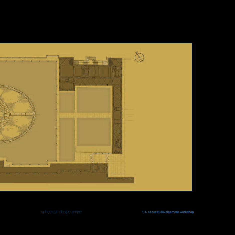
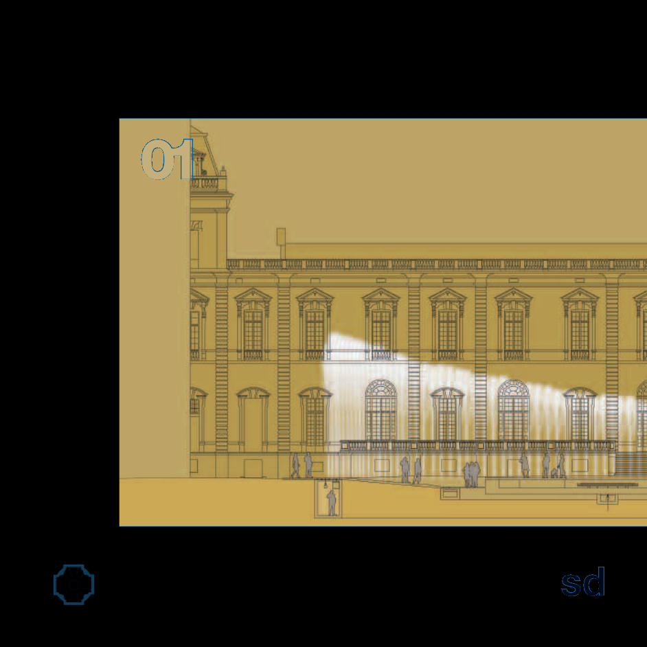
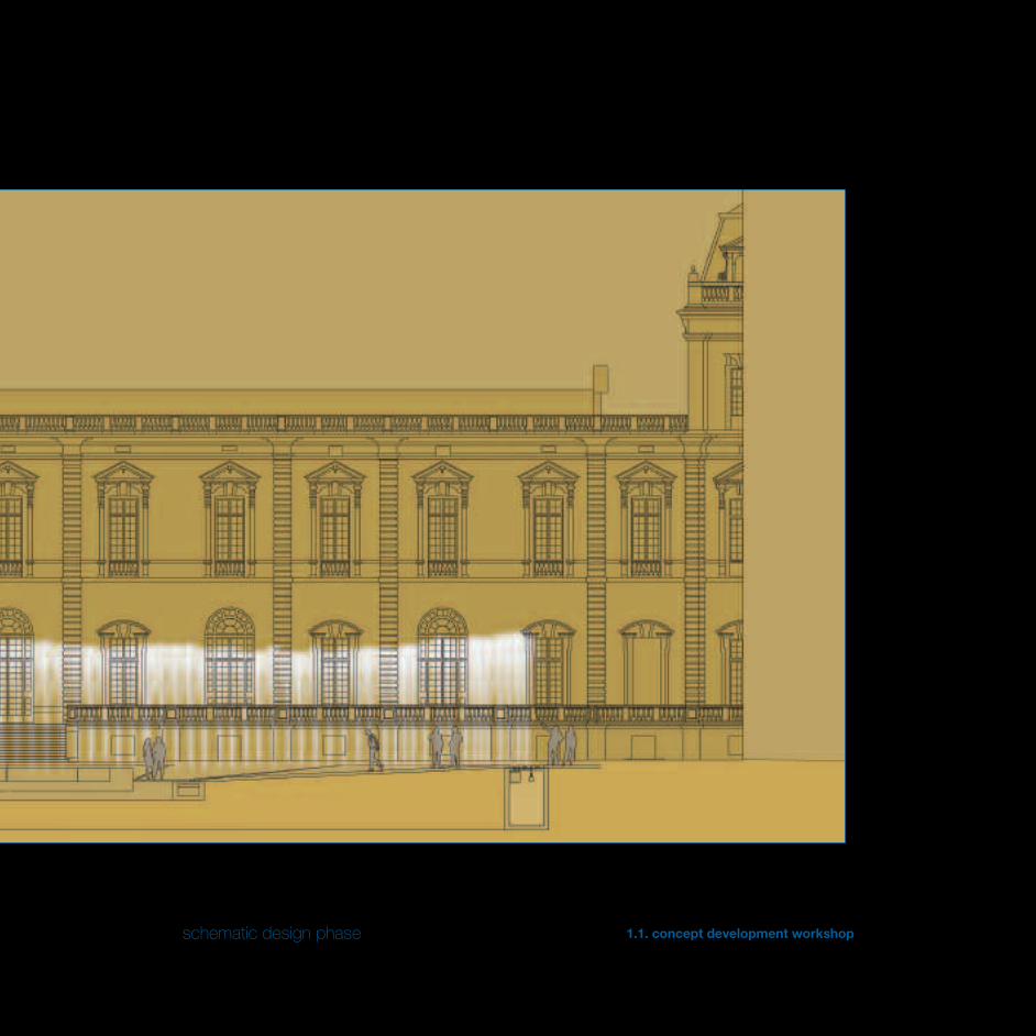
schematic design phase 1.1. concept development workshop
PRELIMINARY REMARKS
The Discover
The presence of a fountain is not an free exercise of de-corative ornament, but it always brings with itself a sym-bolic charge evolving with the succession of technologicaland social progress of the cultures it has dealt with.There are several proofs over centuries and millenniumsabout the water being used as a form of art or as a repre-sentation of religious symbols from the ancient Easterngardens designed to be the perfect harmony between hu-mans and the world, through the hydraulic engineeringof the Ancient Rome and Villa Adriana, Herculaneum andPompeii, not to forget the Spain of the Moors and theshady courtyards of the Alhambra in Granada, up to theGrand Siecle of French gardens.Starting from the end of the 16th century, Royal Palacesand gardens become places for experimentation andinnovation, where fountains permeate of new vitality thestatic sculptural conception of Italian gardens. During themagnificent court receptions, the fountains of the Frenchpalaces represented a sumptuous scenery and, as in atheatre, told the allegory of some mythological scene orcourt life.It is thanks to the genius of a family of Florentine plum-bers, the Francini, that the fountains of Versailles exist,they are pregnant elements of the new concept of garden,which is not a simple extension of the palace any more,but becomes the predominant part of the complex.It is not a case, therefore, that even at the Venaria’s SavoyPalace the magnificence of the buildings matches thesignificant presence of the ancient Deer Fountain: itrepresents a hunting scene and perfectly embodies thegenius loci of the context in which it takes its place, andprecisely the hunting art. The fountain enhancementproject has pursued on one hand the preservation of thearchaeological simple structure and, on the other hand, anew kind of use by reinterpreting the expressive potentialof water tricks in a modern way.The main character of this play is water, which, in itsvarious expressions with a contemplative, playful and orna-mental role, infects the viewers with its energy, conveying toour senses the perception of some of its intrinsic connota-tions, such as plasticity, movement and sound.
PREMESSA
Il Rinvenimento
a presenza di una fontana non rappresenta un eserciziogratuito di abbellimento decorativo, ma da sempre portacon sé una carica simbolica che si è evoluta con ilsuccedersi dei progressi tecnologici e sociali delle cultureche vi si sono confrontate. Numerose sono le testimonianzenel corso dei secoli e dei millenni sull’utilizzo dell’acquacome forma d’arte o rappresentazione di significati reli-giosi: dagli antichi giardini orientali concepiti come armoniaperfetta tra uomo e mondo, passando attraversol’ingegneria idraulica dell’antica Roma e di Villa Adriana,Ercolano e Pompei, senza dimenticare la Spagna dei Mori edei cortili ombrosi dell’Alhambra di Granada, per arrivareal Grand Siecle del giardino francese.Le Regge e i giardini di corte a partire dalla fine del XVI se-colo diventano luogo di sperimentazione e di innovazione,dove le fontane permeano di nuova vitalità la staticaconcezione scultorea dei giardini all’italiana. In occasionedei fastosi ricevimenti di corte le fontane delle reggefrancesi costituivano una sontuosa scenografia e, comein un teatro, raccontavano l’allegoria di qualche scenamitologica o della vita di corte.Al genio di una famiglia di idraulici fiorentini, i Francini, sidevono le fontane di Versailles, elementi pregnanti del nuovoconcetto di giardino, che non è più una semplice estensionedel palazzo, bensì la parte predominate del complesso.Non è un caso, quindi, che anche presso la Reggia Sabaudadi Venaria la magnificenza degli edifici sia accompagnatadalla significativa presenza dell’antica Fontana del Cervo:essa rappresenta una scena di caccia e incarna perfetta-mente il genius loci del contesto in cui si colloca, l’artevenatoria appunto.Il progetto di valorizzazione dellafontana ha perseguito da una parte la conservazione delmanufatto archeologico, dall’altra una nuova fruibilitàmediante la reinterpretazione in chiave moderna dellepotenzialità espressive dei giochi d’acqua.L’attore principale di questa rappresentazione teatrale èproprio l’acqua, che nelle sue varie espressioni in funzionecontemplativa, ludica e ornamentale contagia il pubblicocon la sua energia, trasmettendo ai sensi la percezionedi alcune delle sue connotazioni intrinseche, quali laplasticità, il movimento e il suono.
17th century facade

schematic design phase 1.1. concept development workshop
HISTORY
La Venaria Reale
The Duke Carlo Emanuele II of Savoy was the one wantinga new "residence of pleasure and hunting" to completethe Crown of Delights of the Savoy courts around Turin.Between 1660 and the 1675 approximately, Amedeo diCastellamonte, to whom the project was commissioned,builds the so-called Palace of Diana.In 1716 Filippo Juvarra launches the extension workswhich go on up to the second half of 18th century.Later, the French domain marks the decline of thecomplex that, after its restoration is even used as amilitary barracks. Its oblivion ends in 1997 with the start ofthe restoration works, which still today make it the largestrestoration site in Europe.The entire complex is an environmental and architecturalunicum that encloses the Borgo Antico, the Palace, theGardens and the Mandria Park; a total of 150.000 m2 ofbuilt area, 80 hectares of gardens, 5.000 m2 of frescos.
La Fontana del Cervo
"The current Court of Honour of the castle is the result ofan incomplete destructuring of the Castellammonte com-plex (1659) of the Diana Palace by Michelangelo Garove,first, and Benedetto Alfieri, later. In the place of the greatesplanade joining the current pavilion of the clock to theentrance loggia we can find two courts one after theother, according to a spatial model typical of that period,that preferred a series of visual and functional filters tothe direct view of the residence " – After this transit thelarge courtyard appeared in all its magnificence: framedby the large facade of the Diana Palace, the DeerFountain stood in the middle of the area, it was a marblescene representing a final hunting attack: 12 marble dogs,in the act of throwing themselves upon the prey, theysurrounded, together with four hunters, a bronze deer,made by Boucheron (1665)”.
CENNI STORICI
La Venaria Reale
u il Duca di Savoia Carlo Emanuele II a volere una nuova“residenza di piacere e di caccia” per completare laCorona di Delizie delle corti sabaude intorno a Torino. Trail 1660 e e il 1675 circa, Amedeo di Castellamonte, a cuiera stato affidato il progetto, realizza la Reggia di Diana.Nel 1716 Filippo Juvarra inaugura i lavori di ampliamentoche si protraggono fino alla seconda metà del Settecento.Successivamente il dominio francese segna il declino delcomplesso che, con la restaurazione viene addiritturaadibito a caserma militare. Il suo oblio cessa nel 1997 conl’inizio dei lavori di ristrutturazione, che lo rendonoancora oggi il più grande cantiere di restauro d’Europa.L’intero complesso rappresenta un unicum ambientaleed architettonico che racchiude il Borgo Antico, laReggia, i Giardini e il Parco della Mandria; 150.000 mq disuperficie totale edificata, 80 ettari di giardini, 5.000 mq.di affreschi.
La Fontana del Cervo
“L‘attuale Corte d’Onore del Castello è il risultato incom-pleto della destrutturazione dell’impianto Castellamon-tiano (1659) della Reggia di Diana avvenuta per opera diMichelangelo Garove, prima, e di Benedetto Alfieri, poi.In luogo della grande spianata che congiunge l’attualepadiglione dell’orologio alla loggia di ingresso si trovanoin sequenza due corti, secondo un modello spaziale tipicodel periodo, che alla diretta visibilità della residenza pre-feriva una serie di filtri visivi e funzionali” – “Superato ilpassaggio il Gran Cortile si manifestava in tutta la sua ma-gnificenza: inquadrata dalla grande facciata della Reggiadi Diana, al centro dello spazio sorgeva la Fontana delCervo, scena marmorea rappresentante l’attacco finaledella caccia: dodici cani in marmo, raffigurati nell’atto dilanciarsi sulla preda, circondavano, insieme a quattro cac-ciatori, il cervo bronzeo, opera del Boucheron (1665)”

1721 – Daniel Poppelmann - Zwinger Project

schematic design phase 1.1. concept development workshop
THE IDEA
The project by Carlo Fucini for the implementation of aFountain at the Palace of Venaria Reale.The Water Theatre
During the restoration works of the Court of Honour ofthe Royal Palace, in the summer of 2006, the ancient 17th-century Deer Fountain was brought to light.The direction of the Venaria Reale project and the Supe-rintendence to Architectural and Landscape Heritage po-sitively welcomed the design project of the architect CarloFucini, starting the restoration of the simple structure,with the aim of giving back its centrality to the site byintegrating the ancient fountain in an important projectthat would have had as its core a contemporary, large andtechnologically advanced fountain, that would have beenmore in line with the future use of the court, as a centreof gravity of the monumental architectural complex of theVenaria’s Royal Palace, which was being revealed in allits uniqueness, magnificence and grandeur by thecompletion of the restoration.Even in the 18th century, on the wake of the Renaissanceand Baroque tradition, the German architect MattausDaniel Poppelmann familiarised with the clever hydraulicworks of his time during several journeys to Italy andFrance and applied his skills to the project of the Zwinger,the Royal Palace of Augustus the Strong of Saxony inDresden, where motion water is an integral part of theproject everywhere. A print dated 1721 documents thebrand-new cave he designed. The view show the visitors ofthe Court being locked up in walls formed by verticalwater jets, likewise thin bars that rise and fall, allowingpeople to exit without getting wet. Unfortunately thisfountain doesn’t exist any more and there is littledocumentation on how the water tricks were created.At the Palace of Venaria Reale, along the perimeter of thebasin a large respect zone was created, it is circular andconsists of a double crown of slabs of stone, modelledaccording to a radial scheme, which takes the centre ofgravity of the existing basin as the centre of the layout.
L’IDEA
Il progetto di Carlo Fucini per la realizzazione di unaFontana nella Reggia di Venaria Reale.Il Teatro d’Acqua
urante i lavori di ristrutturazione della Corte d’Onoredella Reggia, nell’estate del 2006, è stata messa in lucel’antica Fontana del Cervo di epoca seicentesca.La Direzione del Progetto La Venaria Reale e laSoprintendenza ai Beni Architettonici e Paesaggisticihanno accolto favorevolmente la proposta progettualedell’architetto Carlo Fucini dandone corso con il restaurodel manufatto e con l’obbiettivo di restituire centralità alluogo integrando l’antica fontana in un importanteprogetto che avrebbe avuto come fulcro una fontanacontemporanea, di grandi dimensioni, tecnologicamenteavanzata e più consona agli usi futuri del cortile, qualebaricentro del complesso architettonico monumentaledella Reggia di Venaria che la fine dei restauri stavafinalmente disvelando, unico, imponente e regale.Già nel XVIII secolo, nel solco della tradizione rinascimen-tale e barocca, l’architetto tedesco Mattaus Daniel Pop-pelmann familiarizzò con le ingegnose opere idraulichedella sua epoca durante viaggi in Italia ed in Francia eapplicò le sue conoscenze al progetto per lo Zwinger, ilpalazzo reale di Augusto il Forte di Sassonia a Dresda,dove l’acqua in movimento è ovunque parte integrantedel progetto. Una stampa datata 1721 documenta lanuovissima grotta da lui progettata. La veduta mostra ivisitatori della corte rinchiusi tra le pareti formate da gettiverticali d’acqua, simili a sbarre sottili che salgono escendono, permettendo alle persone di uscire senzabagnarsi. Purtroppo questa fontana non esiste più è c’èscarsa documentazione su come furono creati i giochid’acqua. Rifacendosi a tale suggestione nella Reggia di Ve-naria, lungo il perimetro esterno della vasca è stata creataun’ampia zona di rispetto, di forma circolare, costituita dauna doppia corona di lastre in pietra, modellate secondouno schema radiale, che assume come centro del traccia-mento il baricentro della vasca esistente.

Preliminary drawings

schematic design phase 1.1. concept development workshop
A second crown of slabs of stone having a wider ellipticalshape than the previous circular crown encloses theancient Deer Fountain and defines the perimeter of theWater Theatre.The ellipse is built on a major axis aligned with the pointsthat connect the aulic entrance of the Diana’s room on thewestern side to the central arc of the Clock Tower on theeastern side, which is known as the "seventeenth-centuryaxis" because originated the orientation of the mostancient architectures of the Royal Palace.The minor axis is traced at right angles to the major axisand it is in line with the entrance of the Great Gallery (theso-called Diana’s).The intersection of the two axis defines the centre of thenew big mountain, actually reconciling that idealalignment that was lost over centuries as a result of thecontinuous succession of demolitions and rebuilding.The drawing shows a subdivision of the ellipse into 192slabs of stone shaped according to a radial scheme, underwhich the nozzles and the spectacular lighting system isplaced, giving life to the Water Theatre.It is important to notice that the ruins of the ancientfountain are below the current countyside line of thecourt. Therefore in rebuilding the flooring plan they tookinto account this and other key elements that set the fixedheights and the differential slopes of the court, such asthe different building entrances, the soakaways forrainwater disposal, the drainage and sewerage systems,the underground equipment rooms, etc.The whole filling area is made of cobblestones, remindingof the original flooring of the fountain, it is divided intoquadrants and marked by 12 rays of different lengths, thatare also made of cobblestones but in different shade ofcolour.Last, on the major axis there are two side walkways ofslabs of stone, arranged to form big steps of a limitedslope in order to allow the access to the lower part of thefilling area to less-able people or simply to those whowould prefer this solution to the cabblestones.
Una seconda corona in lastre di pietra, di forma ellittica emolto più ampia della prima corona circolare, circoscrivel’antica Fontana del Cervo e definisce il perimetro delTeatro d’Acqua. L’ellisse è costruita su un asse maggioreallineato con i punti che collegano l’ingresso aulico dellaSala di Diana a Ovest con l’arco centrale della Torredell’Orologio a Est, noto come “asse seicentesco” perchèoriginò l’orientamento delle architetture più antiche dellaResidenza Reale.L’asse minore dell’ellisse è invece tracciato ortogonal-mente al maggiore ed è allineato sull’ingresso dellaGalleria Grande (detta di Diana).L’incrocio dei due assi definisce il centro della nuovagrande fontana, riconciliando di fatto quell’allineamentoideale, perduto nei secoli in seguito al succedersicontinuo di demolizioni e ricostruzioni.Il disegno illustra una suddivisione dell’ellisse in 192 lastre dipietra sagomate secondo uno schema radiale, sotto le qualisono alloggiati gli ugelli ed il relativo sistema di illumina-zione scenografica che danno vita al Teatro d’Acqua.E’ importante osservare che i resti dell’antica fontana sonosituati al di sotto della attuale linea di campagna del cor-tile. Pertanto nella ricostruzione del piano dipavimentazione si è tenuto conto di questo come di altrielementi cardine che definiscono le quote altimetriche ob-bligate e le pendenze differenziali del cortile, quali i variaccessi agli edificii, le caditoie di smaltimento delle acquepiovane, il sistema di drenaggio, quello fognario, i localitecnici interrati ed altro.L’intero invaso è realizzato in ciotoli, richiamando lapavimentazione originaria della fontana, suddiviso in qua-dranti e segnato da 12 raggi, di differente lunghezza, an-ch’essi realizzati in ciotoli ma di differente cromia.Sull’asse maggiore dell’ellisse sono infine posizionati duecamminamenti in lastre di pietra, disposte a formare deigradoni di limitata pendenza al fine di favorire l’accessoalla parte bassa dell’invaso da parte dei meno abili osemplicemente per chi preferirà questo percorso a quellosui ciotoli.

schematic design phase 1.1. concept development workshop
schematic design phase 1.1. concept development workshop

schematic design phase 1.1. concept development workshop

Interactive Water Feature
schematic design phase 1.1. concept development workshop
ARCHITECTURE AND TECHNOLOGY
From architectural choices to technological solutions
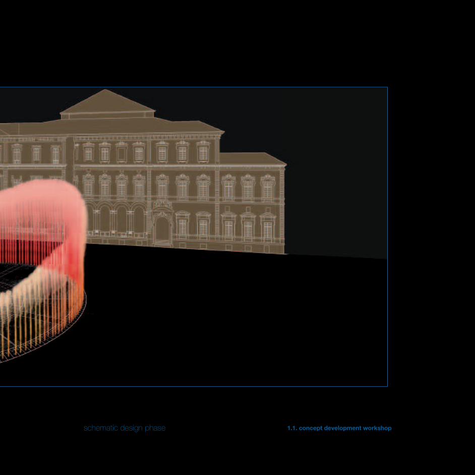
The architectural guide-project in the first place hasprovided for the implementation of a double crown ofslabs of stone in circular disposition to enclose the existingbasin, while a second crown of elliptical shape external tothe first defines the perimeter of the Water Theatre.The total number of the noozles is 96, they are arrangedalternating the slabs of stone and, as required by the callfor tenders, they reach maximum height of 9 metres.Considering the ratio between the surrounding buildingsand the extension of the Court of Honour, the choicewas to refer the water tricks in a dimensional wayboth for number and for height; a less courageouschoice opting for less striking solutions would havecertainly collide with the stature of the Royal Palaceand it would have been taken over. On the contrary,the design solution that has been carried out hasbecome itself the centre of gravity that supports thebalance of the various bodies of the building and it is theirfocal point.
The choreoswitch device
As in a dance, various choreographies are created by theinteractive and sequential movement of jets coming outfrom the flooring. The technological know-how of DeltaEngineering allowed it to meet the requirements ofthe call for tenders, that is to modulate the watertricks in fixed or random sequences or random managedby a software, recreating a sinusoidal movementat different heights, or with static and symmetricalpatterns.The features of the particular device which is called"choreoswitch" not only allow the sequential altimetricmodulation, but it also makes it possible to "play" withwater, breaking from time to time the thin outline of thejets in showers of segments with various shapes that areaddressed to the sky.
TECNOLOGIA E ARCHITETTURA
Dalle scelte architettoniche alle soluzioni tecnologiche
l progetto guida architettonico ha previsto in primo luogo larealizzazione di una doppia corona di lastre in pietra diforma circolare per circoscrivere la vasca esistente, mentreuna seconda corona di forma ellittica esterna alla primadefinisce il perimetro del Teatro d’acqua.Il numero complessivo degli ugelli è pari a 96, dispostiin modo alternato rispetto alle lastre in pietra e, comerichiesto dal bando di gara, raggiungono un’altezzamassima di 9 metri.Visto il rapporto di scala con gli edifici circostanti e l’esten-sione della Corte d’Onore, si è scelto di rapportaredimensionalmente i giochi d’acqua sia per numero che peraltezza; una scelta meno coraggiosa che avesseoptato per soluzioni meno appariscenti, si sarebbesicuramente scontrata con il gigantismo della Reggia e nesarebbe stata fagocitata. Al contrario, la soluzioneprogettuale realizzata è diventata essa stessa il baricentroche reggle l’equilibrio dei vari corpi di fabbrica e necostituisce il punto focale.
Il dispositivo choreoswitch
Come in una danza, numerose sono le coreografie ricreatedal movimento sequenziale ed interattivo degli zampilliche escono dalla pavimentazione. Il know-how tecnolo-gico posseduto da Delta Engineering ha consentito di sod-disfare le richieste del bando di gara, cioè di modulare igiochi d’acqua secondo sequenze prestabilite o casuali ge-stite da un software, ricreando un movimento sinusoidalea diverse altezze, oppure secondo geometrie statiche esimmetriche.Le caratteristiche del particolare dispositivo denominato“choreoswitch” permettono di ottenere non solo la mo-dulazione altimetrica sequenziale, ma anche di “giocare”con l’acqua, spezzando di volta in volta l’esile siluette deglizampilli in raffiche di segmenti di varia forma che vengonoindirizzati verso il cielo.
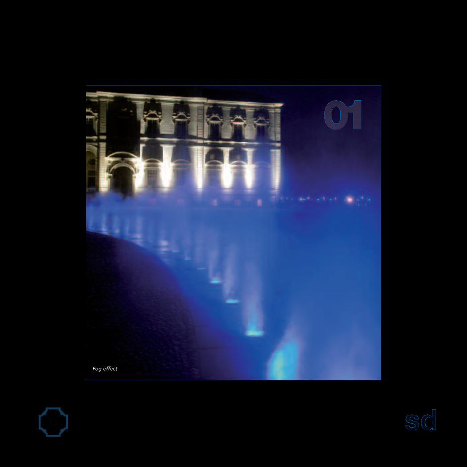
Fog effect

schematic design phase 1.1. concept development workshop
Dance and tricks are therefore expressions of the abilityof water to relate to the place where it is located not onlyin a dimensional way, but also to interact with theaudience.
Light
A fountain must not be lived only during the day. Actually,it should be emphasised as enlightenment is its the natu-ral complement, it enhance and enrich its spectaculareffect; a well-lit installation transforms water from a darkmass into a chromatic kaleidoscope.The Water Theatre made around the Deer Fountain issupported by a lighting system based on the newtechnologies, such as RGB LED, able to make the watertake on a wide range of colours.Each nozzle is equipped with a illuminating body which isable to light up the jet up to its top.
Fog
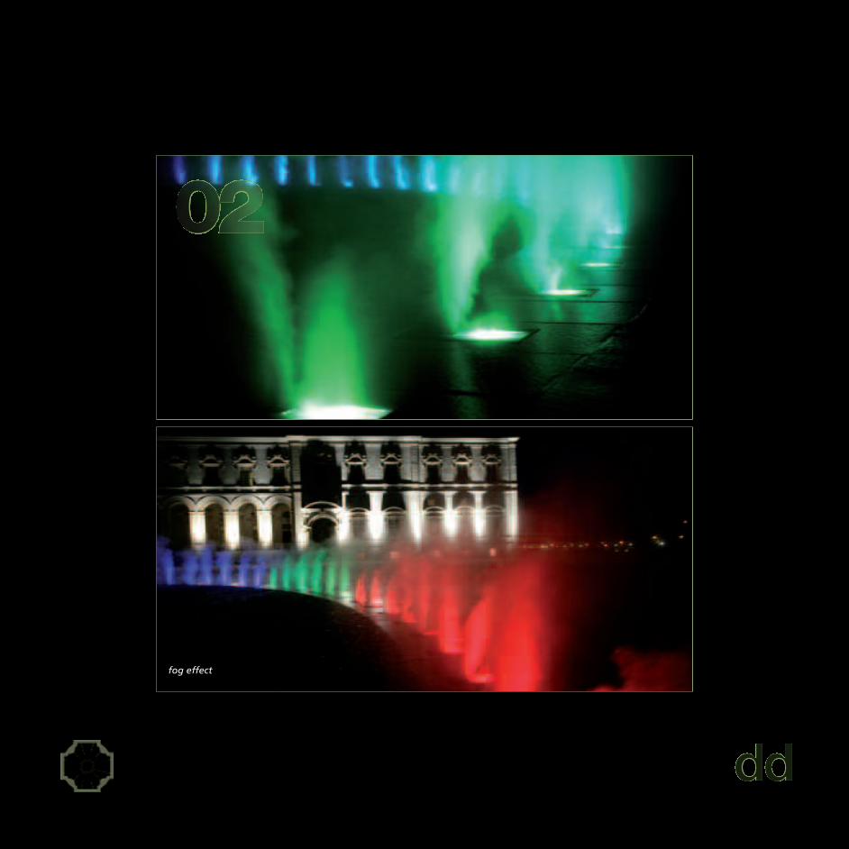
The above described solutions have been further enhancedand enriched with the use the mistscaping effect, that is afoggy curtain having limited height, coming out from theflooring and it takes on thousands of shades by thereflection of light on this impalpable support.The fog is a connection between the close and far space alsoin a time sense; it allows the separation or the union of thesetwo worlds, sometimes playing a protective role, thanks toits power of hiding things and enveloping them in a mysticatmosphere.
Flavors
Among the five senses, the smell is the one that has less linkswith a mediate and reasoned vision of the world. While allthe things that we perceive by the touch or by the viewbecome for us a material that we use for analyzing thesurrounding reality, the olfactory sensations often remaininside us only on an unconscious level, where no rationalanalysis takes place.
Danza e gioco sono quindi espressioni della capacitàdell’acqua di rapportarsi non solo dimensionalmente alluogo fisico in cui si colloca, ma anche di interargire con ilpubblico fruitore.
La luce
Una fontana non va vissuta solo di giorno. Va infattisottolineato come l’illuminazione ne sia il naturalecomplemento, la valorizzi e ne arricchisca l’effetto sceno-grafico; una realizzazione ben illuminata trasformal’acqua da una massa scura in un caleidoscopio cromatico.Il Teatro d’Acqua realizzato intorno alla Fontana del Cervoviene supportato da un impianto illuminotecnico basatosulle nuove tecnologie, quali i LED RGB, in grado di fareassumere all’acqua una vasta gamma di colori.Ogni ugello è attrezzato con un corpo illuminante ingrado di rischiarare lo zampillo fino alla sua sommità.
La nebbia
Le soluzioni fin qui descritte sono state ulteriormente valo-rizzate ed arricchite con l’utilizzo dell’effetto mistscaping,ossia una cortina nebbiosa di altezza limitata che emergedalla pavimentazione e si colora di mille sfumature tramitela riflessione della luce su questo supporto impalpabile.La nebbia rappresenta il tramite tra lo spazio vicino e quellolontano anche in senso temporale; essa permette diseparare o di unire questi due mondi, svolgendo a volte unruolo protettivo grazie alla sua capacità di nascondere lecose e di ammantarle di un’atmosfera mistica.
Gli aromi
Tra i cinque sensi, l'olfatto è quello che ha meno legami conuna visione mediata, ragionata del mondo. Mentre tutto ciòche percepiamo con il tatto o con la vista diventa per noimateriale sul quale riflettere per analizzare la realtà che cicirconda, le sensazioni olfattive spesso rimangono in noi soloa livello inconscio, dove non avviene nessun processo dianalisi razionale.

Interactive Water Feature

schematic design phase 1.2. budgeting
COSTS
Defining the available budget
Very often designers or public authorities have awrong idea of the cost of a fountain. It is important tounderstand from the beginning what type of fountain thecustomer has in mind, and the financial resources on hand.Which makes it possible not to not the expectations of thecontractor and not to design in vain solutions that are asmuch elaborated and impressing as well as unrealizabledue to lack of funds.Sometimes, “outsiders” may miss the complexity of thetechnological equipment implied in the working of afountain in the way we look at it today. The idea ofrelatively simple plumbing and electrical circuits, derivedfrom a traditional concept of a fountain, defines anincorrect estimate of the costs.Among the services offered by Delta Engineering there isthe customer support in order to find the solution withthe best aesthetic result/price ratio.
In the case of the "Water Theatre” at the Royal Palace ofVenaria Reale, thanks to the definition of the project basicguidelines, the development of the concept by thearchitect Carlo Fucini has enabled the Regione Piemonteto define a budget of expenditure as specified in the callfor tenders for a total of €. 530.400,00.
I COSTI
Determinare il budget disponibile
olto spesso i progettisti o le amministrazioni pubblichehanno una errata idea del costo di una fontana.E’ importante capire fin da subito il tipo di fontana che ilcliente sta immaginando e la consistenza delle risorsefinanziarie che vengono messe a disposizione. Questopermette di non deludere le aspettative del committentee di non progettare a vuoto soluzioni tanto elaborate e dieffetto quanto irrealizzabili per mancanza di fondi.A volte, ai non addetti ai lavori può sfuggire la complessitàdegli apparati tecnologici che sottendono il funziona-mento di una fontana come la intendiamo al giornod’oggi; l’idea di un circuito idraulico ed elettrico relativa-mente semplice, derivato dal concetto classico di fontana,determina una errata stima dei costi.Una volta chiarito questo aspetto sarà possibileindividuare la soluzione con il migliore rapporto risultatoestetico/prezzo.
Nel caso del “Teatro d’Acqua” presso la Reggia di VenariaReale, lo sviluppo del Concept a cura dell’arch. CarloFucini ha consentito di individuare in modo chiaro le lineeguida essenziali del progetto; conseguentemente è statopossibile fissare il budget di spesa indicato nel bando digara per un ammontare di complessivi €. 530.400,00.

Interactive Water Feature
schematic design phase 1.3. servicing
REQUISITI GENERALI
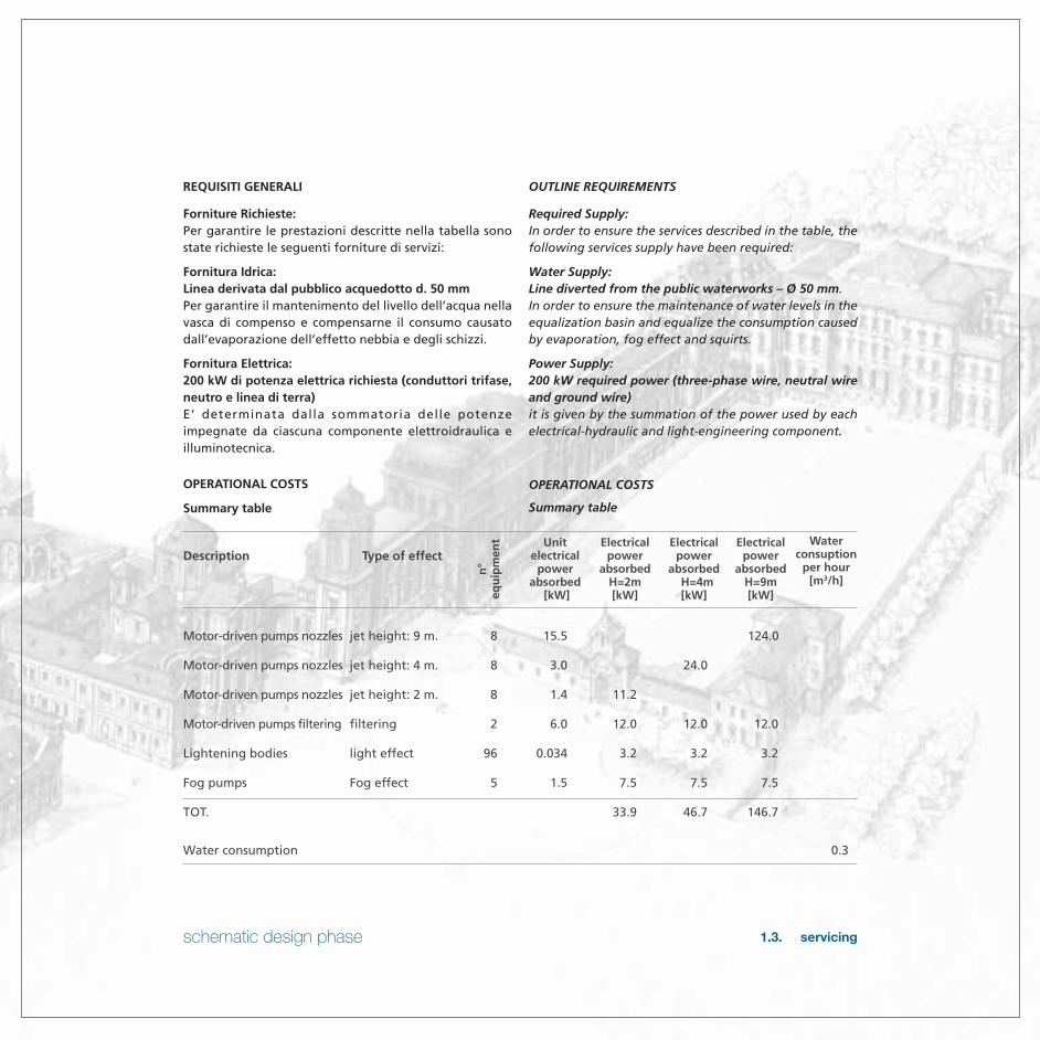
Forniture Richieste:Per garantire le prestazioni descritte nella tabella sonostate richieste le seguenti forniture di servizi:
Fornitura Idrica:Linea derivata dal pubblico acquedotto d. 50 mmPer garantire il mantenimento del livello dell’acqua nellavasca di compenso e compensarne il consumo causatodall’evaporazione dell’effetto nebbia e degli schizzi.
Fornitura Elettrica:200 kW di potenza elettrica richiesta (conduttori trifase,neutro e linea di terra)E’ determinata dalla sommatoria delle potenzeimpegnate da ciascuna componente elettroidraulica eilluminotecnica.
OPERATIONAL COSTS
Summary table
OUTLINE REQUIREMENTS
Required Supply:In order to ensure the services described in the table, thefollowing services supply have been required:
Water Supply:Line diverted from the public waterworks – Ø 50 mm.In order to ensure the maintenance of water levels in theequalization basin and equalize the consumption causedby evaporation, fog effect and squirts.
Power Supply:200 kW required power (three-phase wire, neutral wireand ground wire)it is given by the summation of the power used by eachelectrical-hydraulic and light-engineering component.
OPERATIONAL COSTS
Summary table
Description Type of effect
Motor-driven pumps nozzles jet height: 9 m. 8 15.5 124.0
Motor-driven pumps nozzles jet height: 4 m. 8 3.0 24.0
Motor-driven pumps nozzles jet height: 2 m. 8 1.4 11.2
Motor-driven pumps filtering filtering 2 6.0 12.0 12.0 12.0
Lightening bodies light effect 96 0.034 3.2 3.2 3.2
Fog pumps Fog effect 5 1.5 7.5 7.5 7.5
TOT. 33.9 46.7 146.7
Water consumption 0.3
Waterconsuption
per hour[m3/h]
Electricalpower
absorbedH=9m[kW]
Electricalpower
absorbedH=4m[kW]
Electricalpower
absorbedH=2m[kW]
Unitelectricalpower
absorbed[kW]
n°
equ
ipm
ent

1 preliminary idea01:01 water theater idea •2 schematic plan2.01 constitution of work group • •2.02 presentation of an image package and the levels of finish • •2.03 preliminary architectural concepts • •2.04 process flow diagram •2.05 preliminary mechanical, electrical, structural and architectural planning • •3 application test3.01 water effects simulation test •3.02 lighting and technical effects simulation test •4 development of the plan4.01 planning of a water line forthe loading system ( object of analysis ) • •4.02 planning of electric power feed line to the boards • •4.03 planning of pluri-stage anemometric control • •4.04 planning of a lighting system • •4.05 planning of a draining or lifting system • •4.06 planning of waterproofing • •4.07 planning of ventilation systems • •4.08 planning of data communication (remote control show) • •4.09 planning of fire prevention systems • •4.10 planning of effects pumping stations •4.11 planning of effects pre-filtering and filtering stations •4.12 planning of sand filter pumping stations •4.13 planning of monitoring and disinfectant dosing stations •4.14 planning of elements that pass through and are inserted in the jets and related connections •4.15 planning of overall size of effect nozzles, illuminating bodies and grates that close the holes on the stone •4.16 planning of first filtration elements in the compensation tank •4.17 planning of water network to re-convey to the compensation raceway •4.18 planning of water and electricity distribution to the utilities •4.19 planning of structural elements of the fountain (nozzle housing tank and comp. tank) • •4.20 structural planning of fountain details • •4.21 planning of covering elements • •5 realization of handmade articles and systems5.01 excavation for construction of the technical service room •5.02 casting of lean concrete foundation •5.03 construction of structural and formwork of the technical service room foundation •5.04 positioning of the primary electrical raceways in the formwork •5.05 construction of structural work for taking up of the vertical jets •5.06 positioning of the water stop joints •5.07 casting of the concrete bed •5.08 construction of the structural formwork in the side walls with posit. of stainless steel elements that pass through •5.09 concrete casting •5.10 dismantling of formwork •5.11 technical service room roof construction •
REGIONEPIEMONTE
ARCHITECTUREENGINEERING
DELTAENGINEERING
FOUNTAINTECHNICIAN
HYDRAULICCONSTRUCTION
ELECTRICIAN
ELECTRICALSYSTEM
CONSTRUCTORS
CONTRACTOR
DESCRIPTION OF WORK AT WORKSITE

schematic design phase 1.4. preliminary division of responsibility matrix
5.12 supply of water distribution line and construction of fire prevention systems •5.13 supply of electricity line •5.14 construction of effects pumping stations •5.15 construction of mechanical sand filter pumping stations •5.16 construction of monitoring and disinfectant dosing stations •5.17 construction of fog effect pressurization station •5.18 construction of electrical system of fountain •5.19 construction of lighting system •5.20 construction of ventilation system • •5.21 excavation for construction of connection chase with reservoir tank •5.22 restricted section excavation to make the nozzle housing raceway •5.23 restricted section excavation to make the compensation raceway •5.24 restricted section excavation to make water connections between the two raceways •5.25 casting of lean concrete for cleaning •5.26 positioning of suction, effect delivery and filtration ducts •5.27 positioning of concrete pockets for housing led power feed boards •5.28 positioning of primary and secondary electricity distribution ducts •5.29 positioning of stainless steel manifolds for feeding the nozzles and connecting with the ducts •5.30 construction of the structural work of the raceway and compensation tank foundations •5.31 casting of concrete for the foundations •5.32 construction of the structural work for the side walls of the raceways and the compensation tank •5.33 casting of concrete for side walls •5.34 positioning of the ladder and of the primary grating in the compensation tank •5.35 positioning of the interactive nozzles and construction of the electrical and hydraulic connections •5.36 construction of the roof and covering of the compensation tank •5.37 positioning the removable stones located to cover the nozzle raceway •5.38 completion of the surrounding floor and wide steps •5.39 completion of the electrical system of the utilities (interactive nozzles and luminous bodies) •5.40 completion of fog distribution system •5.41 installation of the luminous bodies and positioning of stainless steel gratings to close the holes •6 system check6.01 thorough cleaning of the raceways and reservoir tank •6.02 loading of the basins •6.03 operational test with reproduction of water and light shows • • •6.04 operational test of filtration and disinfection stations • • •6.05 operational test of the fog effect • • •7 technical documentation7.01 preparaztion of as built drawings (water, electrical) •7.02 preparation of documentaton to be provided (conformity declaration and manual for use) •8 delivery of systems8.01 delivery of systems with instructions to the team for ordinary maintenance • •8.02 drafting of a delivery report of the system for taking up of the systems • •
REGIONEPIEMONTE
ARCHITECTUREENGINEERING
DELTAENGINEERING
FOUNTAINTECHNICIAN
HYDRAULICCONSTRUCTION
ELECTRICIAN
ELECTRICALSYSTEM
CONSTRUCTORS
CONTRACTOR
DESCRIPTION OF WORK AT WORKSITE


schematic design phase 1.5. testing recommendations
ELEMENTS POINTS TO BE TESTED
Grid
When defining the protection grate must garantee utmostefficiency of the beam of light.
Slope
Providing for an adeguate system of slopes is appropriateto limit the loss of water of the circuit and to avoid me-teoric losses.
Noise
Water falling downwards onto the floor generates a si-gnificant acoustic impact. Assessing its environmentalcompatibility is necessary and technical precautions mustbe taken to attenuate it. The pierced surface of the grateis useful for this purpose.
ELEMENTI CRITICI DA TESTARE
Griglia
La definizione della griglia di protezione deve garantirela massima efficienza del fascio luminoso
Pendenza
E’ opportuno prevedere un adeguato sistema di pendenzeper limitare le perdite d’acqua del circuito e per allonta-nare quella meteorica.
Rumore
L’acqua che ricade sulla pavimentazione genera un note-vole impatto acustico. E’ necessario valutarne la compati-bilità ambientale e vanno messi in atto gli accorgimentitecnici atti ad attenuarlo. A questo scopo risulta utile lasuperficie forata della griglia di protezione.


schematic design phase 1.5. testing recommendations
Wind
The anemometric control system must be calibrated on thebasis of the environmental characteristics. It will interveneon the water jet heights in connection with certainthresholds.
Programming
Each element will be singularly programmed as part of ashow: the synchrony between the speed of the wateroutput and the reaction times of the luminous signal mustbe carefully assessed.
Splash
The fountain influence area represents a delicate criticalfactor. It may be precautionarily determined by projectingat 360° from the ground the height of the jets.In any case the variability of environmental conditionssuggest testing splashing when it is windy and, shouldit beI necessary, installing an anemometric controlsystem.Also in this instance the grid dimensions are useful todecrease the inconvenient, recovering most part of thewater splashing down.
Lighting
Choise of the illuminating bodies must be made on thebasis of the height of the water jets which in this casereach a notable height of 9 meters.
Vento
Sulla base delle caratteristiche ambientali va tarato ilsistema di controllo anemometrico che interverràsull’altezza dei getti d’acqua in corrispondenza dideterminate soglie.
Programmazione
Ogni elemento verrà singolarmente programmato comeparte di uno show: va attentamente valutata la sincroniatra la velocità di emissione dell’acqua e i tempi di reazionedel segnale luminoso.
Splash
L’area di influenza della fontana rappresenta un delicatofattore critico. Essa può essere prudenzialmentedeterminata proiettando a terra a 360° l’altezza dei getti.Tuttavia la variabilità delle condizioni ambientali suggeri-scono di testare lo splash soprattutto in presenza di ventoe nel caso si renda necessario di installare un sistemadi controllo anemometrico. Anche in questo caso ledimensioni della griglia posta a terra contribuiscono adattenuare il fenomeno, recuperando gran parte dellacolonna d’acqua in ricaduta.
Illuminazione
La scelta dei corpi illuminanti deve essere fatta in funzionedell’altezza dei getti d’acqua che in questo caso raggiungela notevole misura di 9 mt.


schematic design phase 1.6. general recommendations
RECOMMENDED DESIGN CRITERIA
Assumptions
a) Water Dephts = It is recommended 350 mm. sufficientto install submersible lights.
b) Steps = It is recommended that accessible watersteps have a 400 mm tread and 150 mm riser.This will provide a greater surface area for a child tonegotiate wet changes in grade.All changes in grade within the accessible waterfeature shall step down at a maximum 150 mminterval.
c) Interactive Surfaces = All interactive surfaces shallhave slip-resistant finish.
d) Merging Steps = Steps merging with a slopedplane are to be avoided within the interactivefeature play area. Merging steps can be trip hazardsespecially when children are at play.A good alternative is a ramp layout solution withhandrail.
e) Operational Water Heights = Interactive operationalwater heights shall be limited per discussion heldduring the applications test workshop.
f) Show Mode Operation = Show mode must not havean automatic switch over and must be turned onmanually. In addition, show mode operation must bemonitored to ensure the public does not enter thespace.
g) Splash = Client to confirm splash tolerances for eachwater feature aera.
h) Building Codes = The general intent shouldbe to es tab l i sh bes t prac t i ce cons t ruc t ionmethods.
i) Application Tests = If possible known effects will bereused. On the contrary, it’s suggested to develop newothers to confirm new materials and configurations.
j) S l o p e = T h e a b s o l u t e m a x i m u m s l o p eallowable for a beach sti le entry (similar tothat used for a wave pool) is 1 in 15 or 6,7%.It is recommended that slopes remain well under thisvalue.
K) Safety = When people interact with the fountainthe velocity of water jets spouting must be20 ft per second maximum (equal to an height about2,5 mt).
CRITERI DI PROGETTAZIONE RACCOMANDATI
Presupposti
a) Profondità dell’acqua = Si consiglia una profonditàdi 350 mm. sufficienti ad alloggiare i fari subacquei.
b) Gradini = Si consiglia per gli scalini per l’ingresso inacqua una pedana di 400 mm e un’alzata di 150 mm.Ciò fornirà una superficie più ampia per permettere aibambini di muoversi su superfici bagnate in pendenza.Tutte le modifiche della pendenza all’interno deigiochi d’acqua accessibili dovrebbero scendere a unmassimo di 150 mm.
c) Aree interattive = Tutte le aree interattive devonoessere provviste di bordatura anti-scivolo.
d) Gradini misti = E’ consigliabile evitare gradini mistia superficie scivolosa all’interno dell’area giochiinterattivi. I gradini misti possono essere rischiosi inquanto scivolosi, specialmente in presenza di bambiniche giocano. Una buona soluzione alternativa ècostituita da una struttura a rampa con corrimano.
e) Altezza funzionante dell’acqua = Le altezze interattivefunzionanti dell’acqua devono rispettare i limitiimposti dagli accordi presi durante il test applicativo.
f) Funzione modalità dimostrativa = La modalitàoperativa non deve avere uno switch automatico,ma deve essere impostata manualmente. Inoltre, essadeve essere monitorata per assicurare che il pubbliconon acceda all’area.
g) Spruzzo = Il cliente deve confermare la tolleranzaallo spruzzo per ogni gioco d’acqua.
h) Codici di Costruzione = L’intento generale dovrebbeessere di stabilire le best practice relative allametodologia di costruzione.
i) Test applicativi = Saranno utilizzati ove possibile alcunieffetti già noti. In caso contrario, si consiglia di svilup-parne di nuovi per testare materiali e configurazioni.
j) Pendenza = La pendenza massima assoluta permessaper un’entrata modello spiaggia (simile a quellautilizzata per le piscine ad onde) è 1 su 15 o del 6,7%.Si consiglia di mantenere la pendenza ben al di sottodi questo valore.
k) Sicurezza = Quando il pubblico interagisce con lafontana la velocità massima relativa la fuoriuscitadell’acqua dagli ugelli non deve essere superiore a6 mt/sec (pari ad un’altezza di 2,5 mt circa)

TRAVELLING WAVE BURSTING TRAVELLING WAVE ROCKING CRADLE
UNIFORM JUMPING POPCORN ROMAN CANDLES

The elliptical channel recover part of the water fallingon the ground and convoy it to the compensation runnel
The compensation runnel andthe circular rill bring back thesuperficial water to the reser-voir tank.
Compensation runnel
The elliptical channel
Water switchnozzle
COMPENSATION RUNNEL
THE ELLIPTICAL RUNNEL
schematic design phase 1.7. final schematic design (SD) presentation

FULL PLUMES TURNN ON IN A CHASE SEQUENCE – PARALLEL PATTERN
STATIC WAVE FORMS RISE AND FALL – SYMMETRICAL PATTERN
TWO WAVE FORM CHASE ACROSS THE ARRANGEMENT - PARALLEL PATTERN
ARCHITECTURAL PATTERNS MIRRORED WITH A NEGATIVE PATTERN ON OPPOSING SIDE
COMBINATIONS OF EFFECTS FROM FULL PLUMES, SLUGS, LACE EFFECT AND BALLS OFWATER
BOUNCING SLUG ARRANGEMENT WITH OPPOSING PATTERN
AN ARROW FORM RISES UP AS OPPOSING SIDE FALLS TO THE GROUND

Choreoswitch with plume jetprojected ad a maximumheight of 9000 mm
Choreoswitch device with 1“1/2 plume jet nozzle
90 cm wide by 60 cm deeprunnel
1% slope on the adjoiningsurfaces. On this tract onwhich water flows a coveringthat exploits this effect can berealized.
Pedestrian friendly gratingor architectural paver thatallows water to flow throughthe bottom runnel in todrains
The quick detachable connec-tor allows easy maintenanceof the choreoswitch device
A foggy curtain of limited height emerges from the floor andis coloured in thousands of hues thanks to the rgb led lights.

The elliptical channel recover part of the water fallingon the ground and convoy it to the compensation runnel
The compensation runnel andthe circular rill bring back thesuperficial water to the reser-voir tank.
Compensation runnel
The elliptical channel
Water switchnozzle
COMPENSATION RUNNEL
THE ELLIPTICAL RUNNEL
schematic design phase 1.7. final schematic design (SD) presentation

TECHNICALROOMExample of holes drilled directly into the stone slabs.
this solution does not allow passing of the beam ofthe lights.
Example of a small size grate. As it limits the beam oflight it is suitable for jets of limited height.
The stone slabs are supported by a steeel structure, ar-ranged so as not to interefere with the equipments.
The hole obtained on the slabs hasan appropriate lodging section forthe grate.
The hole obtained on the slabs hasan appropriate lodging section forthe grate.
“Water Theatre”FOUNTAIN NOZZLE ELIPSE
COMPENSATIONTANK
If it is realized in a larger size it can house a seriesof illuminating bodies placed around the centralnozzle.

FOUNTAININFLUENCE AREA
Water Theatre”FOUNTAIN NOZZLE ELIPSE
schematic design phase 1.7. final schematic design (SD) presentation
Hypothesis of a rectangulargrate. This solution allowsmaximum effectiveness of thei l l u m i n a t i n g b o d y a n dreduces the impact surface ofthe down-coming water.
96 non-slip grates alternatedon 192 stone slabs
Compared to the circular hole, the square oneguarantees a better welding outcome

design development
2.1. Applications Testing2.2. General CAD Drawings2.3. Schematic Diagramming2.4. Equipment Room2.5. Components2.6. Costs2.7. Specifications
Applications testing

design development 2.1. applications testing
TESTS
Choreoswitch
Delta Engineering is able to test applications in order tomake a correct design and be preliminarily able to choosethe best installation according to the type of requestedeffect. During this phase of tests it is possible to verify theaesthetic result explaining to the contractor what will bethe impact of the implementation. With the support ofthe applications tests it possible to guide the project linesof the implementation, in order to indicate in the project therequirements to be met to ensure the result of the effect.For the Venaria Reale Fountain the consumption and thelighting-technique characteristics of nozzles and LED bo-dies was tested.Through flow and prevalence measurements we canoptimize the choice of the type of pumps and circuits tobe installed. In this case study we have verified theconduct information provided by Crystal Fountains.In a condition of non-submerged discharge, the chosennozzle has the following performance features:
TESTS
Choreoswitch
elta Engineering è in grado di eseguire dei test applicativiper effettuare una progettazione corretta e poterscegliere a livello preliminare la migliore installazione aseconda del tipo di effetto richiesto. Durante questa fasedi test è possibile verificare il risultato estetico spiegandoalla committenza quale sarà l’impatto della realizzazione.Con il supporto dei test applicativi si possono orientare lelinee progettuali della realizzazione, in modo da indicarein fase di progetto le prescrizioni da seguire pergarantire la riuscita dell’effetto. Per la Fontana di VenariaReale è stato testato il consumo e le caratteristicheilluminotecniche degli ugelli e dei corpi a LED.Attraverso misurazioni di portata e prevalenza possiamoottimizzare la scelta del tipo di pompe e di circuiti dainstallare. In questo caso studio abbiamo verificato i datidi comportamento forniti da Crystal FountainsL’ugello scelto in condizioni di scarico non sommerso ha leseguenti caratteristiche prestazionali:
Nozzle type Q Q tot Jet height Head Spread[l/min] [m3/h] [m] [mca] [m]
Choreoswitch SWS155 57 3 0,9 3,0 0,4
Choreoswitch SWS155 75 4 2,1 5,0 0,7
Choreoswitch SWS155 95 6 3,1 8,0 1,3
Choreoswitch SWS155 109 7 4,0 10,2 1,4
Choreoswitch SWS155 114 7 4,6 11,6 1,5
Choreoswitch SWS155 136 8 6,7 17,4 1,6
Choreoswitch SWS155 163 10 7,3 25,6 3,1
Choreoswitch SWS155 174 10 9,2 30,8 3,4
Choreoswitch SWS155 189 11 10,7 37,5 3,7
Table 2.1 Choreoswitch performance.

Applications testing

design development 2.1. applications testing
Led
From a lighting-technique point of view we tested diffe-rent LED products from companies listed at internationallevel such as Color Kinetics and Space Cannon in order tochoose the more suitable product to illuminate thevertical jets, considering also in a preliminary phase theexact positioning of the LED body and the holecorresponding with the grate put on the final surface.The analysis has concerned various types of parabolsPAR5/PAR20/PAR36, making the choise of the one ableto assure an appropriate luminous effect in differentconditions of use (PAR20)”
Led
al punto di vista illuminotecnico abbiamo testatodifferenti prodotti a LED di ditte quotate a livellointernazionale come Color Kinetics e Space Cannonper scegliere il prodotto più idoneo ad illuminare i gettiverticali, valutando anche in fase preliminare l’esattoposizionamento del corpo a LED e del foro corrispon-dente alla griglia posta sulla pavimentazione finale.L’analisi ha riguardato anche i vari tipi di parabolaPAR5/PAR20/PAR36, indirizzando la scelta su quella ingrado di garantire un adeguato effetto luminoso nellevarie condizioni di utilizzo (PAR20).


design development 2.2. general CAD drawings
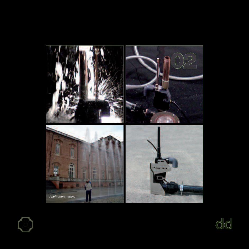
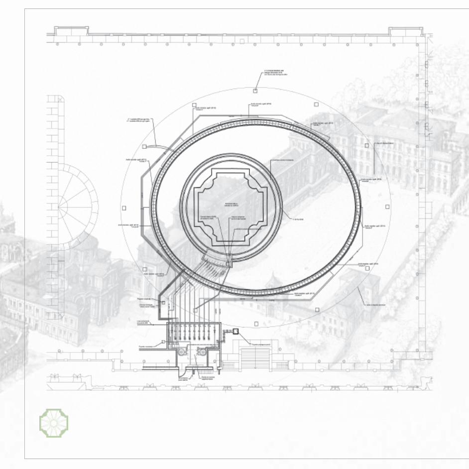
ARCHITECTURAL DETAILING
Starting from the "concept design" phase, studies areextracted and made about architectural detailsandparticular sections that are relevant to the correctinstallation of hydraulic components. The water effectsyou want to recreate depend on a precise positioning ofthe components (nozzles-lights) and by the organizationof the architectural elements such as stones, brushingedges, spillways.During the in-depth analysis of the project the parts ofthe system and of the structure that need more attentionare highlighted during the implementation phase.In this project we have deeply analysed the size ofthe elliptical basin case of the 96 nozzles, the watercollection, the preliminary size of technical room.
By this study design has taken shape:
1. The introduction in the planimetry of the Court ofHonour the structures where to place the pumpingsystems and distribution piping systems, indicating theroute of the lines up to the nozzles. we have indicatedthe canalizations of water return of the nozzles.
2. The development of the section of placement of thenozzle with the maximum water levels andin particular the section with the water levels of thecompensation basin.
During this phase of the project in Court of Honour of thePalace we have defined the wall structures for waterretention, for fixing the nozzles and the position ofpassage of all piping involved in the water treatment, inthe circuits for the vertical jets, in the transit of powerlines for the LED bodies.
PARTICOLARI ARCHITETTONICI
alla fase del “concept design”, vengono estratti e appro-fonditi i particolari architettonici e le sezioni particolariche sono rilevanti ai fini della corretta installazione dellecomponenti idrauliche. Gli effetti d’acqua che si voglionoricreare dipendono infatti da un preciso posizionamentodelle componenti (ugelli-fari) e dalla geometria deglielementi architettonici quali pietre, bordi a sfioro,canalette di raccolta. Nella fase di approfondimento delprogetto si mettono in luce i punti dell’impianto e dellastruttura cui prestare maggiormente attenzione durantela fase realizzativa.In questo progetto sono stati approfondite le dimensionidel bacino ellittico di alloggiamento dei 96 ugelli, la vascadi raccolta dell’acqua, le dimensioni preliminari del localetecnico.
Tramite questo studio si è delineato nella progettazione:
1. L’inserimento nella planimetria della Corte d’Onorele strutture che dovevano alloggiare i sistemidi pompaggio e le tubazioni di distribuzione indicandoi percorsi delle linee fino agli ugelli. Sono stateindicate le canalizzazioni di rientro dell’acqua degliugelli.
2. Lo sviluppo della sezione di alloggiamento degli ugellicon i livelli massimi d’acqua ed in particolare la sezionecon i livelli d’acqua della vascadi compenso.
In questa fase progettuale nella Corte d’Onore dellaReggia sono state definite le strutture murarie darealizzare per il contenimento dell’acqua, per il fissaggiodegli ugelli e la posizione di passaggio di tutte le tubazioniinteressate al trattamento dell’acqua, ai circuiti per glizampilli verticali, al passaggio di linee elettriche perl’alimentazione dei corpi a LED.

design development 2.2. general CAD drawings
ARCHITECTURAL DETAILING
Starting from the "concept design" phase, studies areextracted and made about architectural detailsandparticular sections that are relevant to the correctinstallation of hydraulic components. The water effectsyou want to recreate depend on a precise positioning ofthe components (nozzles-lights) and by the organizationof the architectural elements such as stones, brushingedges, spillways.During the in-depth analysis of the project the parts ofthe system and of the structure that need more attentionare highlighted during the implementation phase.In this project we have deeply analysed the size ofthe elliptical basin case of the 96 nozzles, the watercollection, the preliminary size of technical room.
By this study design has taken shape:
1. The introduction in the planimetry of the Court ofHonour the structures where to place the pumpingsystems and distribution piping systems, indicating theroute of the lines up to the nozzles. we have indicatedthe canalizations of water return of the nozzles.
2. The development of the section of placement of thenozzle with the maximum water levels andin particular the section with the water levels of thecompensation basin.
During this phase of the project in Court of Honour of thePalace we have defined the wall structures for waterretention, for fixing the nozzles and the position ofpassage of all piping involved in the water treatment, inthe circuits for the vertical jets, in the transit of powerlines for the LED bodies.
PARTICOLARI ARCHITETTONICI
alla fase del “concept design”, vengono estratti e appro-fonditi i particolari architettonici e le sezioni particolariche sono rilevanti ai fini della corretta installazione dellecomponenti idrauliche. Gli effetti d’acqua che si voglionoricreare dipendono infatti da un preciso posizionamentodelle componenti (ugelli-fari) e dalla geometria deglielementi architettonici quali pietre, bordi a sfioro,canalette di raccolta. Nella fase di approfondimento delprogetto si mettono in luce i punti dell’impianto e dellastruttura cui prestare maggiormente attenzione durantela fase realizzativa.In questo progetto sono stati approfondite le dimensionidel bacino ellittico di alloggiamento dei 96 ugelli, la vascadi raccolta dell’acqua, le dimensioni preliminari del localetecnico.
Tramite questo studio si è delineato nella progettazione:
1. L’inserimento nella planimetria della Corte d’Onorele strutture che dovevano alloggiare i sistemidi pompaggio e le tubazioni di distribuzione indicandoi percorsi delle linee fino agli ugelli. Sono stateindicate le canalizzazioni di rientro dell’acqua degliugelli.
2. Lo sviluppo della sezione di alloggiamento degli ugellicon i livelli massimi d’acqua ed in particolare la sezionecon i livelli d’acqua della vascadi compenso.
In questa fase progettuale nella Corte d’Onore dellaReggia sono state definite le strutture murarie darealizzare per il contenimento dell’acqua, per il fissaggiodegli ugelli e la posizione di passaggio di tutte le tubazioniinteressate al trattamento dell’acqua, ai circuiti per glizampilli verticali, al passaggio di linee elettriche perl’alimentazione dei corpi a LED.

Process flow diagram

design development 2.3. schematic diagramming
PROCESS FLOW DIAGRAM
Come to this point the plant-engineering features of thecircuits from an hydraulic and electrical point of view. Interms of plant-engineering it is a delicate and importantphase because by the development of these diagrams themajor equipmentnecessary for the plant-engineeringfunctioning of the fountain linked to each other on thefunctional point.In the project for the Venaria Reale Fountain of thePalace, first of all we have separated the circuits that werenecessary for treating the water to those aiming at thespectacular effects. The 96 nozzles placed in an ellipticshape have been divided into 8 circuits made of 12nozzles each.Each circuit is powered by a 18, 5 kW 2 poles motor-drivenpump, which is able to deliver 120 m3/h with a prevalenceof 36 m. Each pump is equipped with a frequencychanger.The total water flow for the functioning of the 96 noz-zles at the maximum height is approximately 16,800 l/min.An anemometric control connected to frequency chan-ger has also been set: if the wind speed is likely to disturbthe perfect verticality of jets, the frequency changerdecreases the flow and the prevalence of pumps byreducing the height of the jets to a condition of security.
The water flow coming out the nozzles partially fallswithin the tunnel where the nozzles are fixed, partiallyflows through the sloping filling area leading to thecollection raceway and from here to the compensationbasin from which it put in circle again by the pumps.We have set a system of automatic priming of filling ofthe deposit basin, to compensate the drop of watervolume due to evaporation and the upstream washingtide of filters.
DIAGRAMMA DEI FLUSSI
Giunti a questo punto vengono definite le caratteristicheimpiantistiche dei circuiti dal punto di vista IDRAULICO edELETTRICO. In termini impiantistici si tratta di una fasedelicata ed importante perché mediante lo sviluppo diquesti diagrammi le principali apparecchiature necessarieal funzionamento impiantistico della fontana vengonocorrelate tra loro dal punto funzionale.Nel progetto della Fontana della Reggia di Venaria Realesi sono stati prima di tutto distinti i circuiti necessari altrattamento dell’acqua da quelli per gli effetti scenogra-fici. I 96 ugelli posizionati in forma ellittica sono divisi in 8circuiti composti da 12 ugelli ciascuno.Ogni circuito viene alimentato da una elettropompa a 2poli da 18,5 kW di potenza, in grado di erogare 120 m3/hcon una prevalenza di 36 m. Ogni pompa è equipaggiatacon variatore di frequenza.La portata d’acqua totale per il funzionamento dei 96ugelli alla massima altezza è pari a circa 16.800 l/min.E’ stato previsto inoltre un controllo anemometricocollegato al variatore di frequenza: qualora la velocità delvento sia tale da disturbare la perfetta verticalità delgetto, il variatore di frequenza diminuisce la portata e laprevalenza delle pompe riconducendo l’altezza dei gettiad una condizione di sicurezza.
La portata d’acqua che fuoriesce dagli ugelli in partericade all’interno del cunicolo dove sono alloggiati gliugelli stessi, in parte scorre lungo l’invaso in pendenza cheporta sino alla canaletta di raccolta e da qui alla vasca dicompenso da cui viene nuovamente rimessa in circolo dallepompe.E’ stato previsto un sistema di caricamento automatico diriempimento della vasca di accumulo, per compensare ladiminuzione del volume d’acqua dovuta all’evaporazionee ai lavaggi in controcorrente dei filtri.

equipment room
design development 2.4. equipment room
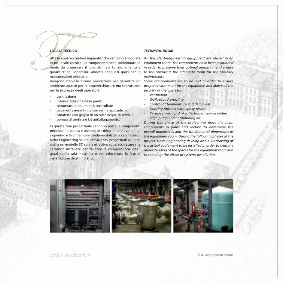
TECHNICAL ROOM
All the plant-engineering equipment are placed in anequipment room. The components have been positionedin order to preserve their optimal operation and ensureto the operators the adequate room for the ordinarymaintenance.Some requirements are to be met in order to ensureproper environment for the equipment and above all thesecurity of the operators:- Ventilation- Walls sound-proofing- Control of temperature and dampness- Flooring finished with epoxy resins- Raceway with grid of collection of service waters- Bilge pump and antiflooding kit.During this phase of the project we place the maincomponents in plant and section to determine theoverall dimensions and the fundamental dimensions ofthe equipment room. During the following phases of theproject, Delta Engineering develop also a 3D drawing ofthe actual equipment to be installed in order to help theunderstanding of the spaces for the equipment room andto speed up the phase of systems installation.
LOCALE TECNICO
utte le apparecchiature impiantistiche vengono alloggiatein un locale tecnico. Le componenti sono posizionate inmodo da preservare il loro ottimale funzionamento egarantire agli operatori addetti adeguati spazi per lemanutenzioni ordinarie.Vengono stabilite alcune prescrizioni per garantire unambiente adatto per le apparecchiature ma soprattuttoper la sicurezza degli operatori:
- ventilazione- insonorizzazione delle pareti- temperatura ed umidità controllate- pavimentazione finita con resine epossidiche- canaletta con griglia di raccolta acque di servizio- pompa di sentina e kit antiallagamento.
In questa fase progettuale vengono poste le componentiprincipali in pianta e sezione per determinare i volumi diingombro e le dimensioni fondamentali del locale tecnico.Delta Engineering nelle successive fasi progettuali sviluppaanche un modello 3D con le effettive apparecchiature cheverranno installate per favorire la comprensione deglispazi per la sala macchine e per velocizzare la fase diinstallazione degli impianti.


design development 2.4. equipment room
TECHNICAL ROOM
All the plant-engineering equipment are placed in anequipment room. The components have been positionedin order to preserve their optimal operation and ensureto the operators the adequate room for the ordinarymaintenance.Some requirements are to be met in order to ensureproper environment for the equipment and above all thesecurity of the operators:- Ventilation- Walls sound-proofing- Control of temperature and dampness- Flooring finished with epoxy resins- Raceway with grid of collection of service waters- Bilge pump and antiflooding kit.During this phase of the project we place in the equip-ment room the main components in plant and section todetermine the overall dimensions and the fundamentaldimensions of the equipment room. During the followingphases of the project, Delta Engineering develop also a3D drawing of the actual equipment to be installed inorder to help the understanding of the spaces for theequipment room and to speed up the phase of systemsinstallation.
LOCALE TECNICO
utte le apparecchiature impiantistiche vengono alloggiatein un locale tecnico. Le componenti sono posizionate inmodo da preservare il loro ottimale funzionamento egarantire agli operatori addetti adeguati spazi per lemanutenzioni ordinarie.Vengono stabilite alcune prescrizioni per garantire unambiente adatto per le apparecchiature ma soprattuttoper la sicurezza degli operatori:
- ventilazione- insonorizzazione delle pareti- temperatura ed umidità controllate- pavimentazione finita con resine epossidiche- canaletta con griglia di raccolta acque di servizio- pompa di sentina e kit antiallagamento.
In questa fase progettuale in the equipment room ven-gono poste le componenti principali in pianta e sezioneper determinare i volumi di ingombro e le dimensionifondamentali del locale tecnico. Delta Engineering nellesuccessive fasi progettuali sviluppa anche un modello 3Dcon le effettive apparecchiature che verranno installateper favorire la comprensione degli spazi per la salamacchine e per velocizzare la fase di installazione degliimpianti.

lighting components by SpaceCannonZumtobel Group

design development 2.5. components
COMPONENTS
According to the type of making of the required effect,we choose the more suitable nozzles, lighting systems, sy-stem of water treatment.
Lighting
The light used for this feature are under water lights andare able to make exiting night sets. They are made of 281.2 Watt LEDs of high flow of light in four-colour process((8 red, 8 green, 8 blue, 4 amber) for total 33.6 Wattspower.The body of the light is made of a technopolymer, whilethe heatsink is in bronze. Each light is powered in 12 VACin accordance with the 64-8 CEI law, by power suppliersthat are placed in 12 sinks outside the ellipse.Thanks to the setting of a DMX local plant, the useof LED technology (RGB) allows the control of eachsingle light and the creation of bright settingswith 16,700,000 different colours.The DMX local plant will be managed together withthe PLC which controls all the nozzles in order toassociate the water tricks to different types of lighteffects.
Water Treatment
In order to retain all impurities and solid particles in thewater we will make a sand filtration system. There will be2 filters with a 100 m3/h flow each and a 50 m3/(h*m2)filtration speed.The water of the 2 filtration lines will be kept in recircu-lation directly in the compensation basin by 2 motor-dri-ven pumps 4 monobloc direct coupling poles with a flowof 72 m3/H each.Therefore, the water in the compensation basin will bethoroughly filtered in 18 minutes.The bacteria and the microbes in the water are notremoved by the filtration, therefore we will set adisinfection system by dichlorine chemical treatment.Without disinfection the fountain can become a good
COMPONENTI
n base al tipo di realizzazione ed effetto richiesto, vengonoscelti gli ugelli, i sistemi di illuminazione, il sistema ditrattamento dell’acqua più idoneo.
Illuminazione
I fari impiegati per questa applicazione sono farisubacquei in grado di realizzare emozionanti scenografienotturne. Sono costituiti da 28 LED da 1,2 Watt ad altoflusso luminoso in QUADRICROMIA (8 colore rosso, 8colore verde, 8 colore blu, 4 colore Ambra) di potenza to-tale pari a 33,6 Watt.Il corpo faro è realizzato in tecnopolimero, mentre ildissipatore è in bronzo. Ogni faro è alimentato in 12 VACin accordo alla norma CEI 64-8 da alimentatori inseriti in 12pozzetti posizionati esternamente all’ellisse.L’utilizzo della tecnologia a LED (RGB) consente, grazie allaprogrammazione di una centralina DMX di controllareogni singolo faro e creare scenografie luminose con16.700.000 differenti colori. La centralina DMX verràgestita in accoppiamento al PLC che controlla tutti gliugelli in modo da poter associare i giochi d’acqua condifferenti tipi di effetti luminosi.
Trattamento Acqua
Al fine di trattenere tutte le impurità e le particelle solidepresenti nell’acqua verrà realizzato un sistema difiltrazione a sabbia. Sono previsti 2 filtri ciascuno diportata pari a 100 m3/h con velocità di filtrazione ugualea 50 m3/(h*m2).L’acqua delle 2 linee di filtrazione verrà mantenuta inricircolo direttamente nellavasca di compenso mediante 2elettropompe 4 poli monoblocco ad accoppiamentodiretto della portata di 72 m3/h ciascuna.L’acqua della vasca di compenso pertanto verrà completa-mente filtrata in 18 minuti.I batteri e i microbi contenuti nell’acqua non vengonoeliminati attraverso la filtrazione per cui verrà predispostoun sistema di disinfezione che si avvale di un trattamento

choreoswitch device by Crystal Fountains
design development 2.5. components
medium for micro-organisms. water could be green, fetidand bearer of many germs. Disinfection keeps water clearand hygienically healthy.In order for the disinfectant to destroy any bacteria inthe water in a few seconds, we need to maintain theparameters of free chlorine and pH within the followingrange:
- free chlorine 0, 6 – 1, 8 ppm.- pH 7, 2 – 7, 4
The fountain will be equipped with a with 2-stations sy-stem of proportional automatic dosage of dichlorine anda solution at 38% of sulphuric acid.Despite the high standards of filtration and sanification isnecessary to indicate the non-potability of the water ofthe fountainMoreover a system of water mitigation will be set inorder to avoid furring due to limescale deposits.
Interactive nozzles
Given the importance of the context and in order toachieve the fountain maximum interactivity, we chose todistribute N° 96 "choreoswitch" nozzles along theoutside ellipse of the historic fountain.The model of 1 "1/2 "choreoswitch" allows to reach the9 meters of maximum requested height and, by permis-sion of the integrated solenoid PLC (Programmable LogicController), guarantees 10 deviations per second with thepossibility of making many water settings. This type ofnozzle allows the proper functioning of the pumpswithout damages due to ram strokes; in fact, when thejet does not come out of the flooring, the pump keeps onworking properly and the nozzle itself divert water indischarge.
chimico a base di dicloro. Senza disinfezione la fontanapuò diventare un ottimo terreno di coltura per microrga-nismi. L’acqua potrebbe presentarsi verde, maleodorantee portatrice di numerosi germi. La disinfezione mantieneun’acqua limpida e igienicamente sana.Affinché il disinfettante possa distruggere in pochi secondieventuali batteri presenti nell’acqua, occorre mantenere iparametri di cloro libero e pH entro un range di seguitoindicato:
- cloro libero 0,6 – 1,8 ppm.- pH 7,2 – 7,4
La fontana verrà dotata di sistema con 2 stazioni didosaggio automatico proporzionale di dicloro e una solu-zione al 38% di acido solforico per la regolazione del pH.Nonostante gli elevati standard di filtrazione e sanificazione ènecessario indicare la non potabilità dell’acqua della fontana.E’ inoltre previsto un sistema di addolcimento dell’acquaper evitare fenomeni di incrostazioni dovute a depositi dicalcare.
Ugelli interattivi
Data la rilevanza del contesto e al fine di realizzare lamassima interattività della fontana, si è scelto di distribuiren° 96 ugelli del tipo “Choreoswitch” lungo l’ellisse esternaalla fontana storica.Il modello “Choreoswitch” da 1”1/2 consente di raggiun-gere i 9 metri di altezza massima richiesta e, medianteil consenso del PLC (Programmable Logic Controller) alsolenoide integrato, garantisce 10 deviazioni al secondocon la possibilità di realizzare numerose scenografied’acqua. Tale tipologia di ugello permette un correttofunzionamento delle pompe senza danneggiamentidovuti a colpi d’ariete; infatti, quando il getto non escedalla pavimentazione, la pompa continua a lavorarecorrettamente ed è l’ugello stesso che devia l’acqua in scarico.
fog effect

design development 2.6. costs
2.5. components
Fog Effect
To further enhance the spectacular effects of thefountain, a cluster has been installed (group of smallnozzles) in correspondence of each nozzle to create a"fog effect". By nebulizing water for a few meters we cancreate spectacular effects and, for example, announce thestart of the operation of the water theatre, involving theviewers in a really charming a atmosphere equal to70 bar.The system is made of 5 high-pressure pumps. The waterof the fog circuit is not recirculated, but it is supplied ina non-returnable way directly by the line of the water-works. It is a question of a total flow of 3,5 m3/h.
Flavors
By borrowing a XVIII century habit, the fountain canperfume the air with essential flavors. By using the meansoffered by modern technology, it is possible to spread inthe air some perfumed substances thanks to a nebulizationimplant. At the beginning they are so strong to inebriatethe smell sense, and then they mitigate until completelydisappearing as soon as the oily component evaporates.
Effetto Nebbia
Al fine di valorizzare ulteriormente gli effetti scenograficidella fontana, è stato installato, in corrispondenza di ogniugello, un cluster (gruppo di piccoli ugelli) per creare un“effetto nebbia”. Nebulizzando l’acqua per pochi metrisi possono creare effetti scenografici e ad esempiopreannunciare l’inizio del funzionamento del Teatrod’acqua, coinvolgendo gli spettatori in un’atmosferaveramente suggestiva.L’impianto è costituito da 5 pompe ad alta pressione paria 70 bar.L’acqua del circuito nebbia non è ricircolata, ma vieneerogata “a perdere” direttamente dal la l ineadell’acquedotto. Si tratta di una portata complessiva paria 3,5 m3/h.
Gli aromi
Mutuando un’usanza del XVIII° secolo, la fontana può pro-fumare l’aria con aromi essenziali. Tramite i mezzi offertidalla moderna tecnologia, è possibile diffondere nell’ariaalcune sostanze profumate attraverso l’impianto dinebulizzazione. All’inizio sono così intense da inebriare ilsenso olfattivo, per poi attenuarsi fino a scomparire non ap-pena le componenti oleose sono completamente evaporate.
COSTS
After developing the main operating details, whichallow choosing the most important plant engineeringcomponents, Delta Engineering is able to verify thecongruity of the costs estimated during the conceptdevelopment phase.
COSTI
Dopo aver sviluppato i dettagli esecutivi più rilevanti,grazie ai quali è possibile selezionare le componentiimpiantistiche principali, Delta Engineering è in grado diverificare la congruità del budget di spesa stabilitodurante la fase di sviluppo del concept.
specifications

design development 2.7. specifications
SPECIFICATIONS
Building a fountain needs appropriate water and powersupplies; moreover, it is necessary to give indicationsrelated to drain pipes and structures waterproofing.Have been given schedules and limitations in order toadjust them to the specificity of each fountain.
SPECIFICHE TECNICHE
a realizzazione della fontana richiede una idoneaalimentazione elettrica ed idrica; inoltre, è necessario ilrispetto di prescrizioni per gli scarichi e per le impermea-bilizzazioni delle strutture. Sono state pertanto fornitetabelle e prescrizioni particolari studiate in modo daadeguarle alla specificità di ogni singola realizzazione.
Unit Totalpower power
Description Type of appliance n° [kW] [kW]
Water motion
Nozzles Centrifugal pump 8 18,500 148,000Filtration Centrifugal pump 2 7,500 15,000Fog effect (optional) High pressure pump 5 1,500 7,500Choreoswitch nozzles 12VAC solenoid 96 0,005 0,480
170,980
Lighting
Nozzle lighting Acquarius LED 96 0,034 3,226Power supplies 96
3,226
Ancillary equipment/Utilities
Technical service room lighting White neon light 3 0,100 0,300Chemical product dosing Dosing pump 2 0,032 0,064Softening system Softener 1 0,035 0,005Bilge pump 2 1,000 2,000Various 0,500
2,869
TOT 177,075
Table 2.7 Summary of powers employed


tender/bid document
3.1. Water Feature Documents3.2. Specifications3.3. Component List3.4. Construction Costs

interactive water feature

tender/bid document 3.1. Water Feature Documents
EXECUTIVE PROJECT
When it takes part to a call for tenders o when it deliversthe design documents Delta Engineering is able toprovide the operational graphic documentation.
- Schematic diagrams of (electrical-Hydraulic) flow- Operational sections and architectural details- Operational analysis of the equipment room in 3D
graphics- Operational analysis of the compensation basin.
PROGETTO ESECUTIVO
l momento di partecipare ad una gara o alla consegnadella progettazione Delta Engineering è in grado difornire la documentazione grafica progettuale esecutiva.
- Diagrammi schematici di flusso (elettrico-idraulico)- Sezioni e particolari architettonici esecutivi- Approfondimento esecutivo del locale tecnico con
grafica 3D- Approfondimento esecutivo della vasca di compenso
3.1. technical room in 3D graphics
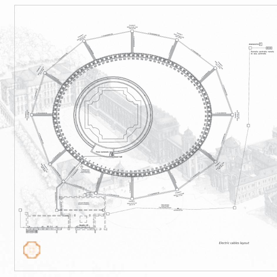
Electric cables layout

Hydraulic pipes layout

tender/bid document

3.1. Water Feature Documents

interactive water feature

tender/bid document
3.2. Specifications
MAINTENANCE
Once we defined all the equipment, all the requests forhydraulic and electrical power needed for the working ofthe fountain are confirmed or not confirmed, possiblyrefining the features we suggested at a first stage.It is in this phase that is also possible to estimate thehydraulic and electrical consumption of the fountain andsubmit a plan of maintenance of the work.
MANUTENZIONE
na volta definite tutte le apparecchiature vengonoconfermate o modificate le richieste elettriche o idraulichenecessarie per l’alimentazione della fontana, eventualmenteaffinando le caratteristiche inizialmente ipotizzate.E’ in questa fase che risulta possibile stimare anche iconsumi idraulici ed elettrici della fontana ed indicare unpiano di manutenzione dell’opera.
Description of operation Frequency of operation
Cleaning of suction pre-filters At least once a week, or when neededCleaning of sock filters which deliver to the nozzles At least once a week, or when neededBackwashing of sand filters At least once a week, or when neededWashing of filtering material of sand filters Twice a yearChecking of chemical products tank and topping up if needed At least once a week, or when neededCleaning and calibrating of pH and Redox sensors Twice a yearChecking of softener Every weekChecking and cleaning of level indicators Every monthChecking of filter incorporated in the nozzles When requiredCleaning of collection raceway When requiredCleaning of sieve grate Once or twice a year, when requiredEmptying and cleaning of compensation tank Once or twice a yearChecking of pumps (overhaul if needed) Once or twice a yearChecking of LED power feed boards Once a year
Table 3.2. Maintenance schedule
COMPONENT LIST
The final calculation of the items quantity and of the kindof components strictly related to the water games isincluded in the bid documents.The detailed determination of every element is a neces-sary prerequisite for allowing to other experts involvedin the realization to evaluate the interaction with what isunder their competence.
LISTA DELLE COMPONENTI
Tra i documenti di gara rientra il computo finale dellequantità degli articoli e delle componenti impiantistichestrettamente inerenti ai giochi d’acqua.L’individuazione dettagliata di ogni elemento costituisceun presupposto necessario per consentire anche aglialtri contrattori di valutarne l’interazione con le lorolavorazioni.
3.3. Component List

interactive water feature

tender/bid document 3.4. Construction Costs
CONSTRUCTION COSTS
Among the services that Delta Engineering is able toprovide to the contracting authority there is also theverification of the construction costs during the prepara-tion of tender documents. As we saw, the definition ofimplementation costs goes through some steps that gofrom identification of the budget in the phase in whichthe concept is developed, to the analytical definition ofcomponents in the phase of design development.In this further check of the estimate of expenditure madein the first project phase, we shall also take into accountthe incidence of labour, site installation costs and costsfor security. This has a vital importance, because it allowsthe identification of the best technological solutions ableto meet the expectations of the contracting authority inrespect of the budget fixed in the call for tenders.
COSTI DI COSTRUZIONE
ra i servizi che Delta Engineering è in grado di fornire alcommittente rientra anche la verifica dei costi dicostruzione durante la fase di predisposizione deidocumenti di gara.Come abbiamo già visto, la definizione dei costi direalizzazione passa attraverso alcuni steps che vannodall’individuazione del budget nella fase in cui vienesviluppato il concept, alla definizione analitica dellecomponenti nella fase di design development.In questa ulteriore verifica delle previsioni di spesafatte nelle prime fasi progettuali si tiene conto anchedell’incidenza della manodopera, dei costi relativiall’allestimento del cantiere e degli oneri per la sicurezza.Ciò risulta di fondamentale importanza, in quantoconsente di individuare le migliori soluzioni tecnologichein grado di soddisfare le aspettative del committente nelrispetto del budget fissato nel bando di gara.
time schedule

construction site

construction
4.1. Bid Phase Assistance4.2. Technical Review4.3. Construction Phase4.4. Water Feature Commissioning Method Statement4.5. Digging and circuits setting4.6. Grid implementation on flooring4.7. Equipment installation4.8. Programming and preliminary testing4.9. Final Testing

interactive water feature

construction
TECHNICAL SUPERVISION
After the design phase we moved to the implementationphase. Delta Engineering is able to follow step by stepthe progress of the works on the site, analysing theconstruction details and finding ad hoc solutions speciallythought for the specific fountain. The meeting betweenthe designers of Delta Engineering and the partiesinvolved in the works is fundamental to explain thedesign choices and proceed to the implementation.After the bid, Delta Engineering uses to provide a seriesof documents aimed to illustrate the realization phase.They include also the definition of the buildingrequirements and of the basic maintenance.
In the last phase of the project some deepening areproduced, by using constructive drawings, which satisfyall the further requests of technical information.
Before starting the works, some technical inspections willbe done in order to verify the conditions of the buildingsite and its effectiveness in the absence of eventualobstacles.
DIREZIONE TECNICA
opo la fase progettuale si è passa alla fase realizzativa.Delta Engineering è in grado di seguire passo passol’avanzamento delle lavorazioni in cantiere approfon-dendo dettagli costruttivi e trovando soluzioni ad hocforgiate appositamente per la specifica fontana.L’incontro tra i progettisti Delta Engineerig e le partiinteressate ai lavori è fondamentale per spiegare le scelteprogettuali e procedere alla realizzazione.Dopo l’espletamento della gara, Delta Engineering èsolita fornire una serie di documenti a supporto della faserealizzativa.Tra questi rientra la definizione dei requisiti costruttivi edella manutenzione di base.
Durante l’ultima fase progettuale vengono prodotti degliapprofondimenti utilizzando dei disegni costruttivi cherispondono a tutte le ulteriori richieste di informazionitecniche.
Prima dell’avvio dei lavori saranno effettuati dei sopral-luoghi tecnici per verificare le condizioni del cantiere ela sua possibile operatività data l’assenza di eventualiimpedimenti.
4.3. construction phase site observation
4.1. bid phase
4.2. technical review

interactive water feature

construction
GENERAL RULES
a. Description of the works
b. Risk analysis
c. Preventive measures
d. Installation of the various activities
e. Location of the various activities
f. Ways of access
g. Schedule of the works
h. Works finishing: verification before the test, test,training for the installation, training for themaintenance.
i. Presence of Delta Engineering technical staff forsetting or modifying the software programming
j. Special considerations on the responsibility from thestarting to the delivery of the implants to the staffwho will be in charge for the maintenance
k. Devices for protecting the public: signals andbarriers
l. Organizational chart of Delta Engineering staff thatis present on the building site for verifying, supervisioning and programming the water games.
m. Starting safety device
n. List of documents (drawings, technical datasheets andtechnical specifications) delivered to the customer
NORME GENERALI
a. Descrizione delle opere
b. Analisi dei rischi
c. Misure di prevenzione
d. Insediamento delle varie attività
e. Ubicazione delle varie attività
f. Vie di accesso
g. Cronoprogramma dei lavori
h. Ultimazione dei lavori: verifica prima del collaudo,collaudo, training per l’avviamento, training per lamanutenzione
i. Presenza di personale tecnico Delta Engineering percaricare o modificare la programmazione del software
j. Considerazioni speciali sulla responsabilità durantel’avviamento fino alla consegna degli impianti alpersonale che si occuperà della manutenzione
k. Dispositivi di protezione per il pubblico: segnaletica etransenne
l. Organigramma del personale Delta Engineeringpresente in cantiere per verificare, supervisionare eprogrammare i giochi d’acqua
m. Dispositivi di sicurezza durante l’avvio
n. Elenco della documentazione (disegni, schede especifiche tecniche) consegnate al committente
4.4. water feature commissioning method statement

digging and circuit settings

construction 4.5. digging and circuits setting
DIGGING AND CIRCUIT SETTINGS
After the digging and the implementation of underpin-nigs, we have intervened with the installation of pipesand conduits, which have been subsequently drownedduring the putting of the structures. This phase of"crude" preparation is very important and it shouldbe planned carefully before starting the works withoutleaving anything to the case, on pain of the failure ofworks, as it is not always possible to intervene in a secondtime with demolitions and rebuildigs that would be tooonerous.On the cleaning lean concrete we carefully positionedthe hydraulic and electrical lines and on the basis of aspecific plan layout; only later we proceeded with thecompletion of the jets made of concrete. During thisphase Delta Engineering Technical Office supports thecompany in the drafting of site-operational design wherewe explain all the operational details.In parallel with the implementation of the ellipse tunnelswe implemented the equipment room; in correspondenceof each pipe we previously placed a special wall duct intothe walls formwork.
SCAVI E POSA CIRCUITI
opo gli scavi e la realizzazione delle sottofondazioni,siamo intervenuti con la posa delle tubazioni e deicavidotti, che sono stati successivamente annegati nelgetto delle strutture. Questa fase di predisposizione “algrezzo” è molto importante e va pianificata attentamenteprima di iniziare i lavori senza lasciare nulla al caso,pena la cattiva riuscita del lavoro, in quanto non sempreè possibile intervenire a posteriori con demolizioni erifacimenti che risulterebbero troppo onerosi.Sul magrone di pulizia sono state scrupolosamenteposizionate le linee idrauliche ed elettriche sulla basedi un preciso tracciamento planialtimetrico; solo successi-vamente si è proceduto al completamento dei getti incalcestruzzo. In questa fase l’ufficio tecnico DeltaEngineering supporta l’impresa nella stesura di disegni“cantierabili” in cui vengono inseriti tutti i particolari esecutivi.Parallelamente alla realizzazione dei cunicoli dell’ellissesi è proceduto alla realizzazione del locale tecnico; incorrispondenza di ogni tubazione passante è statopreventivamente inserito un apposito passamuro nellacasseratura dei muri.

the grid

construction 4.6. grid implementation on flooring
THE GRID
During the implementation phase Delta Engineeringspecifically studied the design and construction of theslotting grid of the LED body. In close cooperation withthe contractor’s demands, the final design of the stainlesssteel grid have resulted from a series of considerationsand sampling, that took into account both aesthetic andfunctional aspects.These are pieces in stainless steel with a non-skid meshand rounded edges, with a lowered transversal surfaceof reinforcement, in order to allow the view of thelongitudinal surface warping of the mesh without crossinterruptions.The finish we chose is a particular treatment ofmicro-shot-blasting and sand-blasting.The overall size of the grid took into account the need tocontain both the splash phenomenon and the noise watermakes in impacting the floor.
LA GRIGLIA
urante la fase realizzativa è stata appositamente studiatoda Delta Engineering il disegno e la costruzione dellagriglia di alloggiamento del corpo faro a LED. In strettacollaborazione con le richieste della committenza ildisegno definitivo della griglia in acciaio è scaturito da unaserie di considerazioni e campionature, che hanno tenutoconto sia dell’aspetto estetico che funzionale.Si tratta di pezzi in acciaio inox con maglia antitacco espigoli arrotondati, con un piatto di rinforzo trasversaleribassato, in modo da consentire la percezione visivadell’orditura longitudinale della maglia senza interruzionia croce.La finitura scelta è consistita in un particolare trattamentodi micropallinatura e sabbiatura.Le dimensioni complessive della griglia hanno tenutoconto della necessità di contenere il più possibile siail fenomeno dello splash che l’inquinamento acusticodovuto all ’ impatto dell ’acqua in ricaduta sullapavimentazione.

equipment installation

construction 4.7. equipment installation
EQUIPMENT INSTALLATION
Delta Engineering took care of the whole installation ofnozzles and lights in the elliptical channel enclosing theancient foundations. A fundamental part for the systemoperation is equipment installation in the equipmentroom.The 3d simulation of the precise location of componentsand pipes routes allows a fast implementation ofduring the installation phase without running into anysurprises.The study of an proper layout and some details, such asthe sailor ladder scale with pull-out handrails to facilitateaccess, creates allows the optimal working conditionsand, above all, security conditions of the operators thatwill follow the management and maintenance of thesystem.
INSTALLAZIONE IMPIANTI
elta Engineering ha curato tutto il montaggio degli ugellie dei fari nel canale ellittico che circoscrive l’antico sedime.Una parte fondamentale per il funzionamentodell’impianto è rappresentata dall’installazione delleapparecchiature all’interno del locale tecnico.La simulazione in 3D dell’esatta collocazione dellecomponenti e dei percorsi delle tubazioni consente diprocedere speditamente durante la fase di montaggiosenza incappare in alcuna sorpresa.Lo studio di un appropriato layout e di alcuni dettagli,come ad esempio la scala alla marinara dotata di mancor-renti estraibili per facilitare l’accesso, consente di metterein condizioni ottimali di lavoro e soprattutto di sicurezzagli operatori che seguiranno la gestione e la manuten-zione degli impianti.

final testing

construction 4.9. final testing
4.8. programming and preliminary testing
PROGRAMMING
The core of the fountain that remains hidden to visitors isthe equipment room, the splendid choreography arestored in the powerboard provided with PLC (programlogic Controller) and DMX device. In Venaria thequalified technicians of Delta Engineering have assembledall the electrical and electronic components in order tomanage and control the fountain.During the preliminary testing the Delta Engineeringtechnicians test the full operation of all the componentsis tested, refining the operational settings in order tobetter satisfy the customer demands and expectations.
PROGRAMMAZIONE
l cuore della fontana che rimane nascosto ai visitatori è illocale tecnico, le splendide coreografie vengonomemorizzate nel quadro elettrico dotato di PLC (programlogic controller) e dispositivo DMX. A Venaria i tecnicispecializzati Delta Engineering hanno assemblato tutte lecomponenti elettriche ed elettroniche al fine di gestire econtrollare la fontana.Durante la fase di precollaudo viene verificato il completofunzionamento di tutte le componenti, affinando leregolazioni operative per soddisfare al meglio le richiestee le aspettative del cliente.
FINAL TESTING
After all the tests and settings of the Fountain, we makethe final testing in the presence of the contractor. Duringthis phase all the potential of the system are shown andthe fountain is officially delivered to the contractor.
COLLAUDO FINALE
Dopo aver eseguito tutti i controlli ed i settaggi dellafontana, alla presenza della committenza viene eseguito ilcollaudo finale. In questa fase vengono mostrate tuttele potenzialità dell’impianto e viene ufficialmente fatta laconsegna alla committenza.


commissioning
5.1. Choreography and programming5.2. Training5.3. Final audit5.4. Final review of all OEM manuals and as
built documentation5.5. Maintenance

fog effect

commissioning 5.1. choreography and programming
COREOGRAFIE E PROGRAMMAZIONE
elta Engineering nella realizzazione delle fontanecon ugelli interattivi e illuminazione a LED in grado dicambiare colore, esegue un’attenta programmazionedegli effetti d’acqua e di luce. Durante la fase diprogrammazione “Off-line” vengono definite leprincipali funzionalità degli effetti. Successivamente,“On-site”, vengono affinati gli effetti e propriodi fronte alla fontana vengono regolati tempi e lesequenze interattive per riprodurre l’effetto richiesto.
CHOREOGRAPHY AND PROGRAMMING
Delta Engineering performs careful programming ofthe water and light effects in the implementation offountains with interactive nozzles and colour-changingLED lighting. During the "off-line" programming phasewe are define the main features of the effects. Then,"on-site", we refine the effects and directly before thewater tricks we adjust times and interactive sequences inorder to reproduce the required effect.
processing pattern of DMX programming
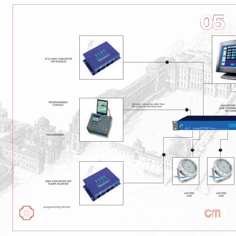
N°22 DMX CONVERTERFOR NOZZLES
PROGRAMMINGCONSOLE SHOWSTORE X
2048 CHANNELRECORDE
DMX CONVERTER FORPUMPS INVERTER
PROGRAMMER
LED RGB33W
LED RGB33W
Optional connection cable fromthe console to the show store
programming devices

commissioning 5.1. choreography and programming
PLC
XLANLS DMXER
MULTIMEDIAPLAYER
LED RGB33W
AMPLIFICATION ANDDIFFUSION SYSTEM
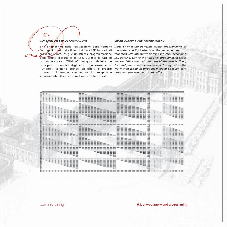
commissioning 5.1. choreography and programming
COREOGRAFIE E PROGRAMMAZIONE
elta Engineering nella realizzazione delle fontanecon ugelli interattivi e illuminazione a LED in grado dicambiare colore, esegue un’attenta programmazionedegli effetti d’acqua e di luce. Durante la fase diprogrammazione “Off-line” vengono definite leprincipali funzionalità degli effetti. Successivamente,“On-site”, vengono affinati gli effetti e propriodi fronte alla fontana vengono regolati tempi e lesequenze interattive per riprodurre l’effetto richiesto.
CHOREOGRAPHY AND PROGRAMMING
Delta Engineering performs careful programming ofthe water and light effects in the implementation offountains with interactive nozzles and colour-changingLED lighting. During the "off-line" programming phasewe are define the main features of the effects. Then,"on-site", we refine the effects and directly before thewater tricks we adjust times and interactive sequences inorder to reproduce the required effect.

choreography and programming

commissioning
Al fine di implementare la tecnologia della fontana etrasformarla in “fontana musicale” in cui gli ugellidanzano seguendo un brano musicale, Delta Engineeringè in grado di pilotarla mediante console DMX utilizzatanormalmente per gestione di show lighting duranteconcerti e grandi spettacoli. Sincronizzando perfetta-mente il movimento degli zampilli, la potenza dellepompe e i colori dei corpi a LED con un brano musicale èpossibile creare suggestivi spettacoli.
In order to implement the technology of the fountain andturn it into a "music fountain" in which the nozzles dancefollowing a piece of music, Delta Engineering is able tomanoeuvre the fountain by DMX console as the onenormally used for managing the lighting show duringconcerts and great performances. By perfectly synchroni-zing the jets movement, the power of pumps and thecolours of the LED bodies with a piece of music it ispossible to create suggestive shows.
Training
Delta Engineering dopo il collaudo finale della fontanaistruisce il personale che avrà in gestione l’impianto. Lagestione di una fontana è necessaria per mantenere neltempo il corretto funzionamento delle apparecchiature.Grazie alle informazioni dei nostri tecnici saranno fornititutti gli elementi utili supportati da manuali e schedetecniche di ogni componente.
Verifica contabile
Tra le possibili verifiche attuabili dopo la fine dei lavori edopo l’avviamento/consegna, rientra quella contabilefinale che analizza l’andamento dei vari stati di avanza-mento e degli scostamenti economici che hanno condottoad eventuali varianti in corso d’opera.
Training
After the final testing of the fountain, Delta Engineeringtrains the staff that will be managing the system. Themanagement of a fountain is indispensable to maintainthe proper operation of the equipment over time. Thanksto the information provided by our technicians we willgive all the usefull elements supported by manuals andtechnical specifications of each component.
Final audit
The possible practicable audits at the end of the worksand after the starting/delivery, include also an accountingaudit aimed to analyze the performance of variousadvancement phases and of the economic deviations,which can cause eventual changes during the works..
5.3. final audit
5.2. training
5.1. choreography and programming
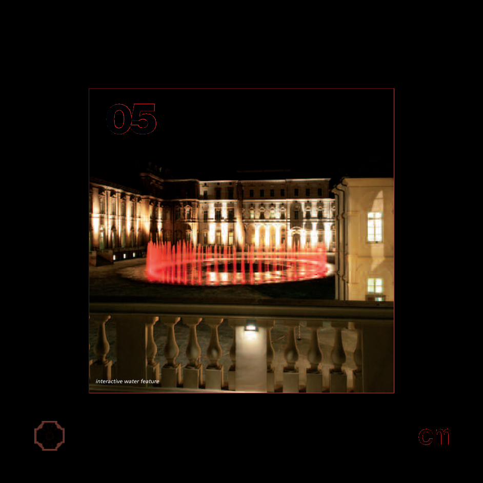
interactive water feature

commissioning
DOCUMENTAZIONE AS BUILT
urante il collaudo finale, Delta Engineering fornisce tuttala documentazione cartacea e su supporto informaticorelativamente ai disegni “AS BUILT” dell’installazionecompleta di manuale di uso e manutenzione e manualioperativi di ogni componente. In questo modo gli opera-tori sono in grado di gestire l’impianto effettuando tuttele operazioni di ordinaria manutenzione.
AS BUILT DOCUMENTATION
During the final testing, Delta Engineering provides allthe printed and electronic documentation related to the"as built" drawings of the installation, the user manualand the maintenance and operational manuals of eachcomponent. In this way the operators are able to managethe systems making all the operations for the ordinarymaintenance.
Manutenzione
Delta Engineering offre per le sue installazioni un serviziodi manutenzione straordinaria. Durante l’anno i nostritecnici eseguono alcuni interventi mirati soprattuttoall’avvio e al fermo impianto. Viene effettuato un con-trollo completo con verifica del corretto funzionamentodelle apparecchiature. Instaurando un rapporto dicollaborazione con gli operatori che gestiscono l’impiantosi riesce a seguirne l’andamento garantendo sempre unfunzionamento corretto e duraturo nel tempo.
Maintenence
For its installations Delta Engineering offers a serviceof extraordinary maintenance. Along the year ourtechnicians give their assistance especially at the start-offand stop of the system. We perform a full test of thesystem, checking the proper operation of the equipment.By establishing a relationship of collaboration withthe operators of the system it is possible to monitor itsoperation, always ensuring correct and lasting in timeoperation.
5.5. maintenance
5.4. Final review of all OEM manuals and as built documentation

115 water feature linear development
96 choreoswitch interactive nozzles
9 m. maximum jet height
0,1 s. water flow deviation time
40 km/h water jet sequential speed
17.000 l/min water in recirculation
40 cubic metres compensation tank
115 9
96
8 67,200
2 16

numbers
8 system pressurization pumps with inverters
2 100 cubic metres/h filtering systems
67.200 lumens provided with 96 LED illuminating bodies
16,7 millions of colours
1 (Programmable Logic Controller) for complete management of the system
infinite possibilities of water choreographies and of lights that can be realized
200 installed electrical power
40
0,1 17.000
1
6,7 infinite
200
40
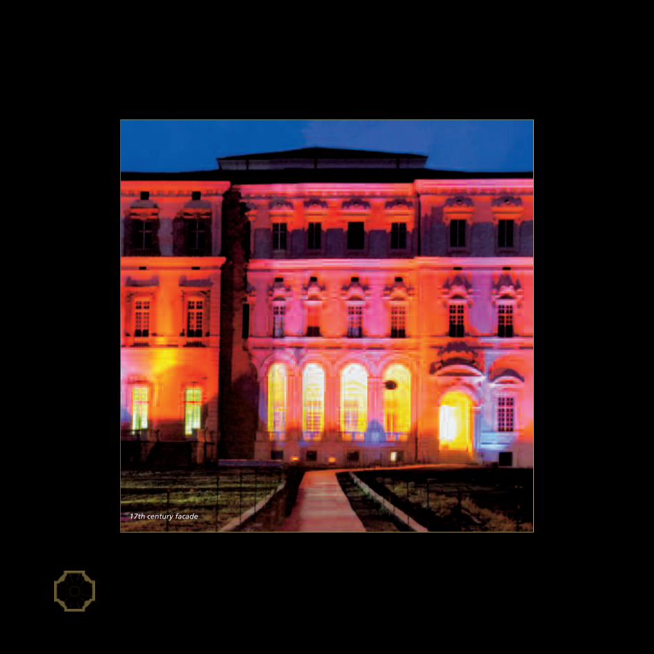
17th century facade

acknoledgments
La Venaria Reale project was promoted and launched in 1998 by the Ministry for Cultural Heritage and Activities andby Regione Piemonte – with the support of the European Union and in collaboration of the Province of Turin, the mu-nicipalities of Turin, Venaria Reale and Druento – and it involved a financial investment of more than 200 million euro.
ACKNOLEDGMENTSDelta Engineering heartfelt thanks all the people that with their availability and cooperation made the making of thisvolume possible.Special thanks to the Direction of La Venaria Reale Project as follows:
Mr. Alberto VanelliCoordinator of La Venaria Reale Project and Flexible Structure of Regione Piemonte
Eng. Francesco PerniceSuperintendent to Architectural and Landscape Heritage
Arch. Maria Grazia FerreriDirector to the Heritage and Specialist of Regione Piemonte
Arch. Mirella MaceraDirector of La venaria Gardens Restoration
Arch. Carlo FuciniCoordinator Back Office
l Progetto La Venaria Reale è stato promosso e avviato nel 1998 da Minstero per i Beni e le Attività Culturali e dallaRegione Piemonte – con il sostegno dell’Unione Europea ed in collaborazione con la Provincia di Torino, i Comuni diTorino, Venaria Reale e Druento – ed ha comportato un investimento finanziario di oltre 200 milioni di Euro.
RINGRAZIAMENTIDelta Engineering rivolge un sentito ringraziamento a tutti coloro che hanno permesso la realizzazione di questovolume per la disponibilità e la collaborazione dimostrate.In particolare si ringrazia la Direzione del Progetto La Venaria Reale così rappresentata:
Dott. Alberto VanelliCoordinatore del Progetto e della Struttura Flessibile La Venaria Reale della Regione Piemonte
Ing. Francesco PerniceSoprintendente per i Beni Architettonici e per il Paesaggio
Dott.ssa Maria Grazia FerreriDirettore al Patrimonio e Tecnico della Regione Piemonte
Arch. Mirella MaceraDirettore degli interventi di recupero dei Giardini della Venaria
Arch. Carlo FuciniCoordinatore Back Office
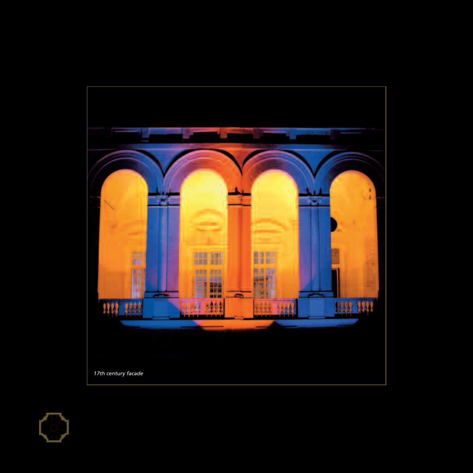
17th century facade

curriculum vitae
Carlo Fucini was born in 1960 in Padua, but he is Turineseof adoption, he has a classical education and took hisuniversity degree in Architecture at the Polytechnic ofTurin, he works with professional offices both in Turin andin Rome.He has always paid particular attention to design, tothe design of structures and setting ups for public andprivate buildings, to the functional recovery of historicalbuildings, mostly in the context of Cultural Heritage.He has carried out some tasks for the executivedevelopment of technologically advanced projects as thefacade of the Bank of Lodi, the Maison Rolex in Basel and
the Arcimboldi Auditorium in Milan, thesheet glass of the Media Center inHannover, teaming up with architects ofinternational stature such as Piano, Mendinie Vignelli.In Turin he has designed La Casa del TeatroRagazzi, the cultural change center CamplusLingotto and other works for the valorisa-tion of Palazzo Civico and the CuriaMaxima in the preparation time for theOlimpic Winter Games in 2006.In Rome he has designed to a large extentof the interior works of Galleria Mazzonianain Termini railway station and in collabora-tion with Roberto Liorni he has signed theproject of the new main office of Istituto
Luce in Cinecittà district, other than several works ofmuseal exibitions and public spaces.In recent years he has coordinated the back-officetechnical activities within the plan of Restoration andEnhancement of Venaria Reale and Savoy residences andsigned projects of furniture and design for the RoyalPalace and the Gardens.
Carlo Fucini, nato a Padova nel 1960, torinese di adozione,studi classici e laurea in architettura al Politecnico diTorino, svolge attività professionale con studio a Torino eRoma.Ha da sempre dedicato particolare attenzione al settoredel design, alla progettazione di strutture e allestimentiper edifici pubblici e privati, al recupero funzionale diedifici storici, prevalentemente nell’ambito dei beniculturali.Ha svolto incarichi per lo sviluppo di progetti tecnologica-mente avanzati come la facciata della Banca Popolare diLodi, la Maison Rolex a Basilea e l’Auditorium degliArcimboldi a Milano, le vetrate del MediaC e n t e r d i H a n n o v e r, a f f i a n c a n d oarchitetti di levatura internazionale fra iquali Piano, Mendini e Vignelli.A Torino ha progettato La Casa del TeatroRagazzi, il centro per scambi culturaliCamplus del Lingotto e altri interventi perla valorizzazione di Palazzo Civico e dellaCuria Maxima nel periodo di preparazionedelle olimpiadi invernali del 2006..A Roma ha disegnato buona parte delleopere interne della Galleria Mazzoniananella Stazione Termini e firmato con RobertoLiorni il progetto della nuova sede dell’Isti-tuto Luce nel comprensorio di Cinecittà oltrea numerosi interventi di allestimentomuseale e per spazi pubblici.Negli ultimi anni è stato coordinatore delle attivitàtecniche di Back Office nell’ambito del progetto diRestauro e Valorizzazione della Venaria Reale e delleResidenze Sabaude ed ha firmato progetti di arredo edesign per la Reggia e i Giardini.

interactive water feature

Delta Engineering Staff
Gianfranco Deganello CEO
Paolo Deganello project architect
Matteo Tortato project engineer
Massimo Migotto business development
Cristiano Dal Bianco project development
Luca Canderle mechanical designer
Alessandro Vezzaro mechanical designer
Fabio Bonin production control manager
Barbara Borriero administrative supervisor
Silvana Lora account assistant
Denni Paolo Sgorlon field technician
Fabio Pilastro field technician
Gabriele Menegazzo field technician
Gianpietro Pasqual field technician
Marco Doro field technician
Massimiliano Spinella field technician
Silvano Bassetto field technician
Silvano Ronchi field technician

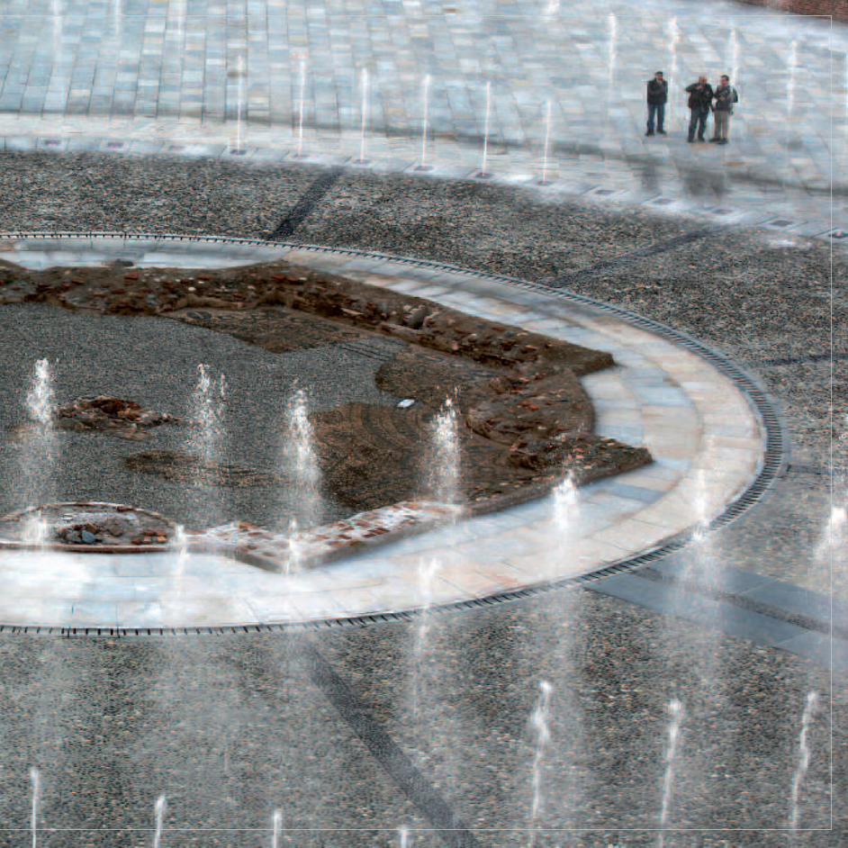


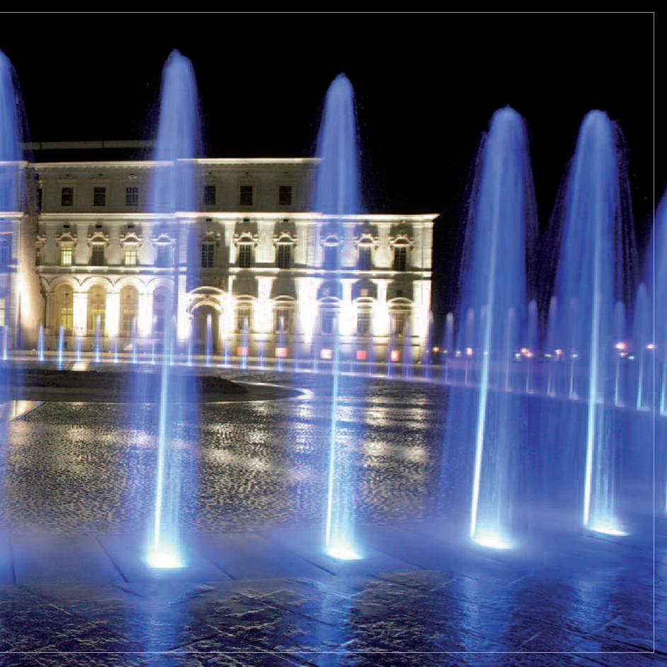


Q U A L I T Y

ISO 9001:2000

C R E D I T S

Delta Engineering srl clientPaolo Deganello arch. editing
Christian Buratti graphic designerQuadrastudio graphic agency
CFS Parallelo 45° photographerMichele D’Ottavio photographerErnesto Mereu photographerProgetto “La Venaria Reale” photographer
Gegraf typography

“The emotion for love of the emotion
is the purpose of art;
the emotion for love of the actions
the purpose of life.”
Oscar Wilde


![THE USE OF CALCULATED DENSITY ON AN OFFSHORE ......Gases byR.F Bukacek ref[3]. Themethod usestheequation:-W=A/P+B where W=thewater content inpounds perMMCF (14.7 psia60 F) P=the pressure](https://static.fdocuments.us/doc/165x107/611e0681b9081420af4a4432/the-use-of-calculated-density-on-an-offshore-gases-byrf-bukacek-ref3.jpg)

