AND STANDBY POWER APPLICATIONS /1/ · 1 August 2014 Change 1, 24 October 2017 . UNIFIED FACILITIES...
82
UFC 3-540-01 1 August 2014 Change 1, 24 October 2017 UNIFIED FACILITIES CRITERIA (UFC) APPROVED FOR PUBLIC RELEASE; DISTRIBUTION UNLIMITED ENGINE-DRIVEN GENERATOR SYSTEMS FOR PRIME \1\ AND STANDBY POWER APPLICATIONS /1/
Transcript of AND STANDBY POWER APPLICATIONS /1/ · 1 August 2014 Change 1, 24 October 2017 . UNIFIED FACILITIES...

UFC 3-540-01 1 August 2014
Change 1, 24 October 2017
UNIFIED FACILITIES CRITERIA (UFC)
APPROVED FOR PUBLIC RELEASE; DISTRIBUTION UNLIMITED
ENGINE-DRIVEN GENERATOR SYSTEMS FOR PRIME
\1\ AND STANDBY POWER APPLICATIONS /1/

UFC 3-540-01 1 August 2014
Change 1, 24 October 2017
UNIFIED FACILITIES CRITERIA (UFC)
ENGINE-DRIVEN GENERATOR SYSTEMS FOR PRIME
\1\ AND STANDBY POWER APPLICATIONS /1/
Any copyrighted material included in this UFC is identified at its point of use. Use of the copyrighted material apart from this UFC must have the permission of the copyright holder. Indicate the preparing activity beside the Service responsible for preparing the document. U.S. ARMY CORPS OF ENGINEERS NAVAL FACILITIES ENGINEERING COMMAND (Preparing Activity) AIR FORCE CIVIL ENGINEER CENTER Record of Changes (changes are indicated by \1\ ... /1/) Change No. Date Location
1 10/24/17 Chapter 3 added to incorporate prime power applications.
This UFC supersedes UFC 3-540-04N, Design: Diesel Electric Generating Plants, and TM 5-811-6, Electric Power Plant Design.

UFC 3-540-01 1 August 2014
Change 1, 24 October 2017
FOREWORD The Unified Facilities Criteria (UFC) system is prescribed by MIL-STD 3007 and provides planning, design, construction, sustainment, restoration, and modernization criteria, and applies to the Military Departments, the Defense Agencies, and the DoD Field Activities in accordance with USD (AT&L) Memorandum dated 29 May 2002. UFC will be used for all DoD projects and work for other customers where appropriate. All construction outside of the United States is also governed by Status of Forces Agreements (SOFA), Host Nation Funded Construction Agreements (HNFA), and in some instances, Bilateral Infrastructure Agreements (BIA.) Therefore, the acquisition team must ensure compliance with the most stringent of the UFC, the SOFA, the HNFA, and the BIA, as applicable. UFC are living documents and will be periodically reviewed, updated, and made available to users as part of the Services’ responsibility for providing technical criteria for military construction. Headquarters, U.S. Army Corps of Engineers (HQUSACE), Naval Facilities Engineering Command (NAVFAC), and Air Force Civil Engineer Center (AFCEC) are responsible for administration of the UFC system. Defense agencies should contact the preparing service for document interpretation and improvements. Technical content of UFC is the responsibility of the cognizant DoD working group. Recommended changes with supporting rationale should be sent to the respective service proponent office by the following electronic form: Criteria Change Request. The form is also accessible from the Internet sites listed below. UFC are effective upon issuance and are distributed only in electronic media from the following source:
• Whole Building Design Guide web site http://dod.wbdg.org/. Refer to UFC 1-200-01, for implementation of new issuances on projects. AUTHORIZED BY:
GEORGE O. LEA, P.E. JOSEPH E. GOTT, P.E. Chief, Military Engineering Branch Chief Engineer U.S. Army Corps of Engineers Naval Facilities Engineering Command
EDWIN H. OSHIBA, SES, DAF MICHAEL McANDREW Deputy Director of Civil Engineers DCS/Logistics, Engineering & Force Protection
Director, Facilities Investment and Management Office of the Deputy Under Secretary of Defense (Installations and Environment)

UFC 3-540-01 1 August 2014
Change 1, 24 October 2017
UNIFIED FACILITIES CRITERIA (UFC) REVISION SUMMARY SHEET
Document: 3-540-01, Engine-Driven Generator Systems for Prime and Standby Power Applications
Superseding:
• UFC 3-540-04N, Design: Diesel Electric Generating Plants
• TM 5-811-6, Electric Power Plant Design
Description: This UFC provides criteria for the design and installation of engine generator systems for use as standby and prime power systems.
Reasons for Document:
• Provide technical requirements for design.
• Consolidate design criteria currently located in multiple documents.
• Update the existing material to reflect new and revised industry standards.
Impact: There are minor cost impacts associated with this UFC. However, the following benefits should be realized:
• Standardized criteria has been prepared to assist engineers in the development of the plans, specifications, calculations, and Design / Build Request for Proposals (RFPs).
• Overlap of material with other UFCs has also been eliminated with the issue of this UFC.
• Adopting NFPA 110 as a basis for engine generator design results in additional requirements; however, these requirements are intended to improve the reliability of emergency generator installations.
Unification Issues
None.

UFC 3-540-01 1 August 2014
Change 1, 24 October 2017
i
TABLE OF CONTENTS INTRODUCTION ....................................................................................... 1 CHAPTER 1
1-1 PURPOSE AND SCOPE. .......................................................................... 1
1-2 APPLICABILITY. ....................................................................................... 1
1-3 GENERAL BUILDING REQUIREMENTS. ................................................ 1
1-3.1 EMI / EMP Protection Systems. ............................................................. 1
1-4 REFERENCES. ......................................................................................... 2
1-5 DESIGN STANDARDS. ............................................................................. 2
1-6 PROJECT REQUIREMENTS. ................................................................... 2
1-7 MISSION FACILITY SUPPORT REQUIREMENTS. ................................. 2
1-8 GLOSSARY. .............................................................................................. 2
STANDBY POWER GENERATORS DESIGN CRITERIA ........................ 3 CHAPTER 22-1 APPLICATIONS. ....................................................................................... 3
2-1.1 Design Guidance. .................................................................................. 3
2-1.2 NFPA 110 Compliance. ......................................................................... 3
2-1.3 NFPA 70 and NFPA 110 Compliance. ................................................... 4
2-2 AUTHORIZED FUEL TYPES. ................................................................... 4
2-3 ONSITE FUEL STORAGE CAPACITY. .................................................... 4
2-4 ANALYSIS REQUIREMENTS. .................................................................. 5
2-4.1 Design Analysis. .................................................................................... 5
2-4.2 Environmental. ....................................................................................... 6
2-4.3 Seismic Classification. ........................................................................... 8
2-4.4 Fuel Storage Design and Capacity. ....................................................... 8
2-4.5 Utility Requirements for Paralleling. ....................................................... 8
2-4.6 Power Rating Category. ......................................................................... 8
2-4.7 Performance Class Transient Limits. ..................................................... 9
2-5 DESIGN CRITERIA. ................................................................................ 11
2-5.1 Circuit Wiring for Legally Required and Optional Standby Systems. ... 11
2-5.2 Automatic Operation. ........................................................................... 11
2-5.3 Single Operation Generator Sets. ........................................................ 12
2-5.4 Requirements for Paralleling. ............................................................... 13
PRIME POWER GENERATORS ............................................................. 15 CHAPTER 3

UFC 3-540-01 1 August 2014
Change 1, 24 October 2017
ii
3-1 PRIME POWER GENERATORS. ............................................................ 15
3-1.1 Purpose. .............................................................................................. 15
3-1.2 Definitions. ........................................................................................... 15
3-1.3 Renewable Power. ............................................................................... 16
3-2 PRIME POWER GENERATOR CLASSIFICATION. ............................... 16
3-2.1 Rating Classification. ........................................................................... 16
3-2.2 Application Classes. ............................................................................ 16
3-2.3 Fuels Classification. ............................................................................. 16
3-3 GENERATOR TYPE................................................................................ 16
3-4 PRIME POWER GENERATOR DESIGN. ............................................... 17
3-4.1 Reliability, Availability and Maintainability (RAM). ................................ 17
3-4.2 Capacity Factors. ................................................................................. 17
3-4.3 General Requirements. ........................................................................ 17
3-4.4 Generator Sets. ................................................................................... 17
3-4.5 Liquid Fuel Systems. ........................................................................... 18
3-4.6 Air Intake System. ................................................................................ 18
3-4.7 Lubrication System. ............................................................................. 19
3-4.8 Cooling System. ................................................................................... 19
3-4.9 Exhaust / Air Emissions Control System. ............................................. 19
3-4.10 Starting System. .................................................................................. 19
3-4.11 Control System. ................................................................................... 19
3-4.12 Direct Current (DC) Power System. ..................................................... 22
3-4.13 Paralleling Switchgear. ........................................................................ 22
3-4.14 Distribution Switchgear. ....................................................................... 22
3-4.15 Split Bus. .............................................................................................. 23
3-4.16 Black Start Generator. ......................................................................... 23
3-4.17 Communications and Alarms. .............................................................. 23
3-5 ENVIRONMENTAL.................................................................................. 24
3-6 COMMISSIONING. .................................................................................. 24
3-7 GENERATOR PLANT SECURITY. ......................................................... 24
APPENDIX A REFERENCES ....................................................................................... 25
APPENDIX B EXAMPLES ............................................................................................ 29

UFC 3-540-01 1 August 2014
Change 1, 24 October 2017
iii
B-1 SINGLE GENERATOR SYSTEM CONFIGURATIONS. ......................... 29
B-1.1 Single Engine Generator Supply to Essential Loads. .......................... 29
B-1.2 Permanently Installed Engine Generator with Portable Connection. ... 29
B-1.3 Single Engine Generator Configuration for Whole Building Supply. .... 30
B-1.4 Single Engine Generator Configuration with Multiple ATS. .................. 31
B-1.5 Single Engine Generator with Redundant Utility Supply. ..................... 32
B-1.6 Dual Engine Generator with Redundant Utility Supply. ........................ 33
B-2 PARALLEL GENERATOR SYSTEM CONFIGURATIONS. .................... 34
B-2.1 Utility Supply. ....................................................................................... 34
B-2.2 Parallel Generator Control Systems. ................................................... 35
B-3 AUTOMATIC TRANSFER SWITCH CONFIGURATIONS. ..................... 36
APPENDIX C CHECKLIST ........................................................................................... 39
C-1 GENERAL. .............................................................................................. 39
C-2 ELECTRICAL. ......................................................................................... 39
C-3 MECHANICAL. ........................................................................................ 41
C-4 CIVIL / STRUCTURAL. ........................................................................... 43
C-5 ARCHITECTURAL. ................................................................................. 43
APPENDIX D GENERATOR SIZING ........................................................................... 44
D-1 LOAD EVALUATION. ............................................................................. 45
D-1.1 Uninterruptible, Essential, and Nonessential Loads. ............................ 45
D-1.2 Conditions of Loading. ......................................................................... 46
D-1.3 Nonlinear Loads. .................................................................................. 46
D-1.4 Step Loading. ....................................................................................... 46
D-1.5 Motor Starting Requirements. .............................................................. 47
D-2 GENERATOR RATING. .......................................................................... 47
D-2.1 Industry Ratings. .................................................................................. 47
D-2.2 Generator Capacity Rating. ................................................................. 48
D-2.3 Uninterruptible Power Supply (UPS) Systems. .................................... 48
D-2.4 Power Quality. ..................................................................................... 49
APPENDIX E CONNECTION METHODS FOR PORTABLE GENERATORS ............. 51
E-1 INTRODUCTION. .................................................................................... 51
E-2 CONNECTION METHODS. ..................................................................... 51

UFC 3-540-01 1 August 2014
Change 1, 24 October 2017
iv
E-2.1 MIL-C-22992, Class L, QWLD-Rated Connectors. .............................. 51
E-2.2 Single-Pole (Cam-Lok style) Connectors. ............................................ 52
APPENDIX F FACILITY DESIGN TYPES .................................................................... 55
APPENDIX G AIR FORCE REQUIREMENTS .............................................................. 61
G-1 AUTHORIZATIONS. ................................................................................ 61
APPENDIX H POWER PLANT CONSIDERATIONS ................................................... 63
H-1 PLANT LOCATION FACTORS. .............................................................. 63
H-2 ACOUSTICAL CONSIDERATIONS. ....................................................... 64
H-3 PRIME POWER PLANTS. ....................................................................... 64
H-3.1 Boiler Requirements. ........................................................................... 64
H-3.2 Load Requirements. ............................................................................ 64
APPENDIX I GLOSSARY ............................................................................................. 71
I-1 ACRONYMS. ........................................................................................... 71
I-2 DEFINITION OF TERMS. ........................................................................ 73
TABLES
Table 2-1 Generator Noise Level Regulation .............................................................. 8 Table 2-2 Performance Class Transient Limits ......................................................... 11

UFC 3-540-01 1 August 2014
Change 1, 24 October 2017
1
INTRODUCTION CHAPTER 1
1-1 PURPOSE AND SCOPE.
This Unified Facilities Criteria (UFC) has been issued to provide criteria for the design of engine driven generator systems for standby and prime power applications.
The information provided here must be utilized by engineers in the development of the plans, specifications, calculations, and Design / Build Request for Proposals (RFP) and serves as the minimum design requirements. It is applicable to the traditional services customary for Design-Bid-Build construction contracts and for Design-Build construction contracts. Project conditions may dictate the need for a design that exceeds these minimum requirements.
1-2 APPLICABILITY.
Compliance with this UFC is mandatory for the design and installation of engine-driven (fossil fueled) generator systems for standby and prime power applications at all DoD installations. The connection of generator systems to a facility is covered by this UFC. Refer to Appendix E regarding generator connection design criteria. This UFC does not apply to tactical engine generators.
1-3 GENERAL BUILDING REQUIREMENTS.
Comply with UFC 1-200-01. UFC 1-200-01 provides applicability of model building codes and government unique criteria for typical design disciplines and building systems, as well as for accessibility, antiterrorism, security, high performance and sustainability requirements, and safety. Use this UFC in addition to UFC 1-200-01 and the UFCs and government criteria referenced therein. Also, review siting for possible damage from flooding, wind/wind-blown debris, and seismic events.
Modernization of existing systems for the sole purpose of meeting this UFC design criteria is not required. Upgrades or modifications of existing facilities should consider the design criteria in this UFC, but it is not intended that an entire facility require modernization solely because of a minor modification to a part of the facility.
1-3.1 EMI / EMP Protection Systems.
Prime power generators and switchgear that serve mission critical, mission essential and C4ISR facilities must be evaluated for protection from electromagnetic interference (EMI) and electromagnetic pulse (EMP) in accordance with TM 5-690, QSTAG 244, Edition 4, MIL-STD-461C and MIL-STD-2169. Operation and maintenance of generator facilities must not introduce unacceptable levels of degradation into EMI / EMP survivability of a system scored to the above criteria. To ensure continued EMI / EMP survivability, a Life Cycle Nuclear Survivability program must be established in accordance with AR 70-75, DoDD 500.1, and DoDI 3150.09.

UFC 3-540-01 1 August 2014
Change 1, 24 October 2017
2
1-4 REFERENCES.
Appendix A contains a list of references used in this UFC. References applicable to a specific topic are also listed and described in the appropriate sections of this UFC.
1-5 DESIGN STANDARDS.
Codes and standards are referenced throughout this UFC. The publication date of the code or standard is not routinely included with the document identification throughout the text of the document. In general, the latest issuance of a code or standard has been assumed for use.
1-6 PROJECT REQUIREMENTS.
Provide analyses that document the multi-discipline requirements and impacts of the following:
• Facility – features and siting for passive survivability.
• System sizing and rating.
• System configuration.
• System operation and control.
• Physical and cybersecurity.
• Emissions and permitting.
• Noise mitigation.
• Seismic classification.
• Fuel.
• Utility requirements for paralleling.
Appendix C provides a checklist of items to consider as part of system planning and design.
1-7 MISSION FACILITY SUPPORT REQUIREMENTS.
The generator design must be based upon the mission’s requirements for transient and steady state loads, startup, charging of uninterruptable power supply (UPS), etc.
1-8 GLOSSARY.
Appendix G contains acronyms, abbreviations, and terms.

UFC 3-540-01 1 August 2014
Change 1, 24 October 2017
3
STANDBY POWER GENERATORS DESIGN CRITERIA CHAPTER 2
2-1 APPLICATIONS.
Refer to Appendix F for a list of facility types and typical applications within DoD. For the Army and Navy, the major command or program element determines if a generator system for standby power is required and its classification.
2-1.1 Design Guidance.
Provide designs for non-medical backup power applications in accordance with IEEE Std 446 IEEE Recommended Practice for Emergency and Standby Power Systems for Industrial and Commercial Applications. Refer to UFC 4-510-01 for generator system requirements associated with Medical Military Facilities.
2-1.2 NFPA 110 Compliance.
For permanently installed generator systems, comply with the NFPA 110 requirements for emergency power supply systems (EPSS) with the following clarifications.
2-1.2.1 Classification.
Designate the EPSS as Class X, where “X” is the required operating time in hours.
Designate the EPSS as Type 10 for medical systems covered by UFC 4-510-01 and Type 60 for all other applications.
2-1.2.2 Remote Manual Stop.
Provide a remote manual stop station for the EPSS in one of the following locations:
• In a separate room of the same building that houses the generator system.
• In a separate building the generator system is serving.
• On the outside of the building that houses the generator system.
• On the outside of an enclosure that contains the generator system.
The requirement for a remote manual stop station may be deleted, such as when it has been determined that a location is not available that restricts access to unqualified operators. The designer of record must receive documentation from the activity that the fire chief or designated equivalent concurs with this determination.
2-1.2.3 Remote Control and Alarm.
Provide a remote control and alarm panel for the EPSS in a separate room of the same building that houses the generator system or in a separate building that the generator system is serving. The requirement for a remote control and alarm panel may be

UFC 3-540-01 1 August 2014
Change 1, 24 October 2017
4
deleted when it has been determined that a location is not available that restricts access to unqualified operators or if not desired by the activity. The designer of record must receive documentation from the activity for this determination.
Provide a remote common audible alarm to a 24 hour staffed location when the EPSS location is not staffed 24 hours per day. The requirement for a remote common audible alarm may be deleted when it has been determined that a suitable location is not available or if not desired by the activity. The designer of record must receive documentation from the activity for this determination.
2-1.3 NFPA 70 and NFPA 110 Compliance.
Comply with NFPA 70 and NFPA 110 as follows.
• Generator systems that are required to comply with NFPA 70 Article 700, Emergency Systems, must also comply with NFPA 110 Level 1 criteria.
• Generator systems that are required to comply with NFPA 70 Article 708, Critical Operations Power Systems (COPS), must also comply with NFPA 110 Level 2 criteria.
• Systems utilizing permanently installed generators that are not designated as Emergency Systems or COPS must comply with NFPA 70 Article 701, Legally Required Standby Systems, and comply with NFPA 110 Level 2 criteria.
• Systems utilizing portable generators must comply with NFPA 70 Article 702, Optional Standby Systems.
2-2 AUTHORIZED FUEL TYPES.
Select fuel oil (diesel or jet fuel) as the primary fuel source for applications where onsite storage is required. Natural gas may be used as the primary fuel source only for applications where onsite storage is not required.
• Diesel / natural gas dual fuel units are allowed. For the Air Force, natural gas systems are not allowed.
• Bio-diesel and liquefied petroleum gas (LPG) fuel types are not allowed.
2-3 ONSITE FUEL STORAGE CAPACITY.
Provide a minimum of seven days of fuel storage either in a dedicated on-site main fuel tank or from a confirmed delivery source. If the fuel storage is from a confirmed delivery source, ensure the delivery source can provide reliable deliveries during long-duration power outages. Base this storage capacity on the fuel consumption required to support the mission load. When the seven-day requirement is accomplished by a delivery source, provide each generator set with a minimum local 24-hour capacity tank based on the full-load fuel consumption rate of the engine.

UFC 3-540-01 1 August 2014
Change 1, 24 October 2017
5
The above requirements may be modified when it is validated (documented in writing and dated) that mission operations require a different operational duration (longer or shorter). For Army Secure Critical Missions, the Army will reduce the risk by being capable of providing necessary energy and water for fourteen days. See Army Directive 2017-17.
2-4 ANALYSIS REQUIREMENTS.
2-4.1 Design Analysis.
Provide a design analysis which covers the general facility design requirements in accordance with UFC 1-200-01 and its referenced documents. Document in the design analysis how compliance with NFPA 37, NFPA 70, and NFPA 110 is achieved. In addition to the UFC 3-501-01 requirements for preliminary basis of design and follow-on submittals (Short Circuit Analysis, Protective Device Time-Current Coordination Study, Arc Flash Analysis, Voltage Drop Analysis, Motor Starting/Flicker Analysis), provide the following general system specific analysis information:
2-4.1.1 Facility – Features and Siting.
• Facility design features for maintenance, including lay-down space for major overhauls and access for repair by replacement, without removal of major components or building system equipment/features.
• Geographic and operating environment, including coastal locations / corrosive conditions, humidity, altitude, seismic zones, and ambient temperature extremes.
• Exhaust system design, including stack height, sampling port orientation, and location.
• Vibration (transmitted to structures).
• Ventilation.
2-4.1.2 Engine Generator Sizing.
• Generator sizing calculations. The Designer of Record must use commercially available generator sizing software provided by a generator manufacturer to determine the required rating. Refer to Appendix D for additional information regarding generator sizing. Verify the commercially available sizing software addresses the generator sizing topics listed in Appendix D.
• Accommodate the effects or rating adjustments for nonlinear loads, transformer in-rush, motor starting, and uninterruptible power supply (UPS) systems.

UFC 3-540-01 1 August 2014
Change 1, 24 October 2017
6
2-4.1.3 System Configuration.
• Classification of loads.
• Redundancy (reliability, availability, maintainability factors).
• Maintenance and testing.
2-4.1.4 System Operation and Control.
• Load shed plan.
• Communications Plan.
• Electrical Protection Scheme.
• Modes of Operation Delineation and Impacts Analysis.
• Refueling capability to support generator operation during extended power outages at mission essential / critical facilities.
2-4.1.5 Focused Electrical System Analysis.
Perform harmonic analysis where switching power supplies contribute 25% or greater to the system loads, and/or electromagnetic filters are installed to mitigate the effects of high-energy electromagnetic pulse (EMP).
2-4.2 Environmental. Evaluate environmental requirements (e.g. noise, air pollution, wildlife, storm water) developed during the initial project planning stages.
• Verify site is suitable for construction (e.g. are wetlands present, is the ground contaminated) without major environmental impacts
• Field verify, through environmental and biological surveys, that impacts will be minimal and can mitigated.
• All design and construction will provide electrical systems which must comply with Federal, State, and local environmental regulations. For overseas locations, follow the guidance specified in Host Nation-specific Final Governing Standards, or if none exists, the current DoD Overseas Environmental Baseline Guidance Document (OEBGD) and applicable Host Nation laws. For Air Force, consult AFI 32-7006 for additional guidance.
2-4.2.1 Environmental Studies and Permitting.
Plan for a permitting process that may take years, with duration depending upon the selected system and the locality (country, State, county and municipality) that is jurisdictionally responsible. Federal, state, and local requirements will vary with the local ambient air quality, size of the project and potential emissions. All new or modified stationary power generators (both engine and turbine based) are required to comply

UFC 3-540-01 1 August 2014
Change 1, 24 October 2017
7
with applicable EPA New Source Performance Standards (NSPS). The specific characteristics of an emissions source determine the applicability of a particular NSPS. See 40 CFR Part 60 Subpart GGKKKK Stationary Gas and Combustion Turbines, or NSPS IIII Stationary Compression Ignition Internal Combustion Engines, or NSPS JJJJ Stationary Compression Ignition Internal Combustion Engines. Studies and permitting requirements exist at all levels (Federal, State, and local) and may include:
• 316(a) – Thermal discharge.
• 316(b) – Cooling water intake.
• Air permitting.
• Aquatic ecology.
• Avian and bat studies / protection.
• Cultural resources.
• Dredge and fill.
• Endangered species.
• Encroachment.
• Erosion and sediment control.
• Floodplain management.
• Lake management.
• Land and right-of-way grants.
• Native American consultation.
• Natural resources.
• National Environmental Policy Act;
Environmental Assessments (EAs) −
Environmental Impact Studies (EISs) −
• Noise / Odor.
• River crossing permits.
• Transmission line routing.
• Stormwater / Water quality.
• Wetlands permitting, mitigation and design.
2-4.2.2 Noise Mitigation.
Comply with federal, state, and local codes, and for overseas locations host nation laws, for maximum noise levels permitted at property line or Table 2.1, whichever is less. Use

UFC 3-540-01 1 August 2014
Change 1, 24 October 2017
8
A-weighting filter criteria (dBA) as adopted by OSHA as the official regulated sound level unit.
Table 2-1 Generator Noise Level Regulation
Noise Zone Peak Daytime
dBA
Peak Nighttime
dBA
Continuous Daytime
dBA
Continuous Nighttime dBA
Residential 62 52 57 47 Light Industrial 67 57 62 52
Heavy Industrial 72 62 67 57 Hospital 45 40 35 30
2-4.3 Seismic Classification.
Comply with UFC 1-200-01, including all referenced criteria and standards.
2-4.4 Fuel Storage Design and Capacity.
Apply UFC 3-460-01 to petroleum fuel facilities designs.
2-4.5 Utility Requirements for Paralleling.
Where the generation equipment is connected to the utility’s system bus and is required to operate in parallel with the utility’s electric system, comply with specific utility provider guidelines on parallel generation connection accommodations. For the Air Force, equipment authorization inventory data (EAID) or real property installed equipment (RPIE) generators or any generator owned by another agency will not operate in parallel with any utility provider unless authorized by AFCEC/CO in accordance with AFI 32-1062.
2-4.6 Power Rating Category.
Determine the required power-rating category in accordance with Electrical Generating Systems Association (EGSA) 101P for DoD facilities and ISO 8528-1 for host nation facilities, as appropriate.
Each manufacturer has developed their own unique rating definitions that may, or may not comply with these standards.
2-4.6.1 Continuous Power.
The maximum power, which the generating set is capable of delivering continuously while supplying a constant electrical load when operated for an unlimited number of hours per year under the agreed operating conditions with the maintenance intervals and procedures being carried out as prescribed by the manufacturer.

UFC 3-540-01 1 August 2014
Change 1, 24 October 2017
9
Note: The continuous power category is unlikely to be required for the standby power applications associated with this UFC.
2-4.6.2 Prime Power.
The maximum power which a generating set is capable of delivering continuously while supplying a variable electrical load when operated for an unlimited number of hours per year under the agreed operating conditions with the maintenance intervals and procedures being carried out as prescribed by the manufacturer. Prime power is also defined by IEEE 446 as “The source of supply of electrical energy that is normally available and used continuously day and night, usually supplied by an electric utility company, but sometimes supplied by base-loaded user-owned generators.” EGSA Standard 101P defines a prime power generator as a utility type power plant that will deliver continuous power under normal varying load factors.” Wind turbines or solar generation cannot by definition be prime power.
Note: The prime power rating category is required for generator systems designated as critical operations power systems (COPS) in accordance with NFPA 70 Article 708.
2-4.6.3 Limited Time Running Power.
The maximum power available, under the agreed operating conditions, for which the generating set is capable of delivering for up to 500 hours of operation per year with the maintenance intervals and procedures being carried out as prescribed by the manufacturers.
2-4.6.4 Emergency Standby Power.
The maximum power available during a variable electrical power sequence, under the stated operating conditions, for which a generating set is capable of delivering in the event of a utility power outage or under test conditions for up to 200 hours of operation per year with the maintenance intervals and procedures being carried out as prescribed by the manufacturers.
2-4.7 Performance Class Transient Limits.
Determine the required electrical performance class in accordance with ISO 8528-1, Reciprocating internal combustion engine driven alternating current generating sets — Part 1: Application, ratings and performance, and as described below. Transient response limits are provided in Table 2-2 in accordance with ISO 8528-5:2013, Reciprocating internal combustion engine driven alternating current generating sets - Part 5: Generating sets.
2-4.7.1 Class G1.
Connected loads require only basic parameters of voltage and, such as general purpose lighting and other simple electrical loads.

UFC 3-540-01 1 August 2014
Change 1, 24 October 2017
10
2-4.7.2 Class G2.
Applies to generating set applications where the required voltage characteristics are very similar to those for the commercial public utility electrical power system with which it operates. When load changes occur, there may be temporary but acceptable deviations of voltage and frequency. Examples of this category include lighting systems, pumps, fans, and hoists.
2-4.7.3 Class G3.
Applies to applications where the connected equipment makes severe demands on the stability and level of the frequency, voltage, and waveform characteristics of the electrical power supplied by the generating set. Examples of this category include telecommunications and thyristor-controlled loads. Note that both rectifier and thyristor-controlled loads may need special consideration with respect to their effect on generator-voltage waveform. Class G3 loads require an evaluation by the designer of record to document the system voltage and frequency limitations, including transient response.
2-4.7.4 Class G4.
Applies to applications where the demands made on the stability and level of the frequency, voltage and waveform characteristics of the electrical power supplied by the generating set are exceptionally severe. Examples include data-processing equipment or computer systems. Class G4 loads require an evaluation by the designer of record to document the system voltage and frequency limitations, including transient response.

UFC 3-540-01 1 August 2014
Change 1, 24 October 2017
11
Table 2-2 Performance Class Transient Limits
Parameter Performance Class
G1 G2 G3 G4 Frequency Deviation (Percent) for 100 Percent Load Increase <-15 <-10 <-7 TBD
Frequency Deviation (Percent) for 100 Percent Load Decrease <+18 <+12 <+10 TBD
Frequency Recovery Time (Seconds) for 100 Percent Load Change <10 <5 <3 TBD
Voltage Deviation (Percent) for 100 Percent Load Increase <-25 <-20 <-15 TBD
Voltage Deviation (Percent) for 100 Percent Load Decrease <+35 <+25 <+20 TBD
Voltage Recovery Time (Seconds) for 100 Percent Load Change <10 <6 <4 TBD
Frequency Droop (Percent) <-8 <-5 <-3 TBD
Steady-State Frequency Band (Percent) <2.5 <1.5 <0.5 TBD
Steady-State Voltage Regulation (Percent) <5 <2.5 <1 TBD Note: The Table 2-1 column for performance class G4 states “TBD”, which means that a site-specific analysis is required to determine the voltage and frequency limits.
2-5 DESIGN CRITERIA.
Note: Appendix B provides examples of various configurations.
2-5.1 Circuit Wiring for Legally Required and Optional Standby Systems.
For Legally Required (NFPA 70 Article 701) or Optional Standby Systems (NFPA 70 Article 702), keep the circuit wiring from the generator to the loads served entirely independent of all other general wiring unless otherwise permitted in NFPA 70 Article 700.
2-5.2 Automatic Operation.
Use fixed (permanently installed) generators with automatic startup for facilities designated as emergency and COPS systems. Generators associated with facilities designated as standby systems may be either fixed or portable with automatic or manual operation. Generators configured for automatic operation shall be equipped with intelligent electronic controls to protect the generator sets and manage startup, operation, and shutdown.

UFC 3-540-01 1 August 2014
Change 1, 24 October 2017
12
2-5.3 Single Operation Generator Sets.
2-5.3.1 Configuration.
Configure single operation generator sets as separately derived systems.
Provide four-pole devices for a three-phase system to switch the supply to essential loads and to switch between multiple single operation generator sets.
2-5.3.2 Automatic Transfer Switches.
Use automatic transfer switches (ATS) that are listed in accordance with UL 1008, Automatic Transfer Equipment. Provide automatic transfer switches with integral maintenance bypass isolation for systems designated as Emergency, COPS, or where validated (documented in writing and dated) by the user as being required.
A design using double-throw safety switches to accomplish maintenance bypass is not allowed under any circumstances.
Provide an open transition transfer scheme unless facility operating procedures require paralleling with the utility. Closed transition transfer is rarely required for standby power applications. Closed transition will require coordination with the local utility and will require designing for the higher available short circuit current of the combined parallel power sources.
2-5.3.3 Metal Clad/Metal Enclosed Switchgear.
Provide free standing metal clad or metal enclosed switchgear as required for generator voltage rating, load capacity, fault capacity (withstand/interrupting ratings), paralleling requirements, and operating scenarios.
Non-enclosed ATS must be in a dedicated isolated compartment when installed in switchgear or switchboards. This is for protection of personnel.
2-5.3.4 Automatic Transfer Switch Maintenance Access.
Provide switchboard or switchgear construction with draw out power or insulated case circuit breakers for the main power distribution equipment. Provide working clearance around each circuit breaker when in its withdrawn position in accordance with NFPA 70 Table 110.26 (A) (1).
2-5.3.5 Utility Service.
Provide draw out circuit breakers as the utility service disconnecting means when redundant utility services are provided to allow for maintenance without incurring power outages.

UFC 3-540-01 1 August 2014
Change 1, 24 October 2017
13
2-5.4 Requirements for Paralleling.
2-5.4.1 Parallel Operation with Public Utility.
Where the generation equipment is connected to the utility’s system bus and is required to operate in parallel with the utility’s electric system, comply with IEEE 1547 – Series, and specific utility provider guidelines on parallel generation connection agreements.
For the Air Force, equipment authorization inventory data (EAID) or real property installed equipment (RPIE) generators or any generator owned by another agency will not operate in parallel with any utility provider unless authorized by AFCEC/CO in accordance with AFI 32- 1062.
2-5.4.2 Parallel Operation with Other Distributed Energy Resources.
Where the generation equipment is connected to a local electrical distribution system bus and is required to operate in parallel with the other distributed energy generation resources (DERs) in islanded mode, comply with IEEE 1547 – 4.
For the Air Force, equipment authorization inventory data (EAID) or real property installed equipment (RPIE) generators or any generator owned by another agency will not operate in parallel.
2-5.4.3 Main Power Distribution Equipment.
Provide switchboard or switchgear construction with draw out power or insulated case circuit breakers for the main power distribution equipment. Provide a minimum of 30 inches of working clearance around each circuit breaker when in its withdrawn position.
2-5.4.4 Control Power.
Provide redundant AC control power for systems designated as Emergency, COPS, or where validated by the user as being required. Provide a redundant AC control power system that is selectable via an automatic transfer switch.
Provide redundant DC control power for systems designated as Emergency, COPS, or where validated by the user as being required. Provide a redundant DC control power system through a best battery selector.
2-5.4.5 Control System.
Provide the following:
2-5.4.5.1 Provide generator and electrical system protection in accordance with IEEE Std 446 IEEE Recommended Practice for Emergency and Standby Power Systems for Industrial and Commercial Applications and IEEE Std. 242 Recommended Practice for Protection and Coordination of Industrial and Commercial Power Systems. Provide intelligent electronic devices (IEDs) to control the logic for all programmed and operator initiated automatic system sequences. The control system must control and

UFC 3-540-01 1 August 2014
Change 1, 24 October 2017
14
monitor the main breakers, the tiebreakers, the feeder breakers (if load shedding is required), and the common system auxiliaries.
2-5.4.5.2 Redundant IEDs that run the logic for all programmed and operator initiated automatic system sequences. The redundant master programmable logic controllers (PLCs) via paralleled input / output points must control and monitor the main breakers, the tiebreakers, the feeder breakers (if load shedding is required), and the common system auxiliaries.
2-5.4.5.3 Separate and dedicated generator controllers that run the logic for operation of each respective generator set. Automatic startup of the generator sets must be via commands from the master controllers. Design system so that manual startup of the generator sets is via operator initiated commands independent of the master controllers. The generator controllers must control and monitor the generator breakers and associated generator set auxiliaries.
2-5.4.5.4 Close control commands for synchronizing that are direct outputs from separate controllers for each respective utility source and generator circuit breaker.
2-5.4.5.5 System operator interface via minimum 15 inch TFT (thin film transfer) color touch panels. Provide a touch panel for each generator set plus one additional local panel and an optional remote panel. Each display controller must provide real-time graphical control and monitoring for the system and all generators.
2-5.4.5.6 Communication should be via Ethernet and support IEC 61850 communications functions and protocols for SCADA and relay devices.
2-5.4.5.7 Breaker control switch for each main breaker, tie breaker, feeder breaker (if control is required for load shedding), and generator breaker to enable automatic control when the switch is in the “normal after close” position and disable automatic control when the switch is in the “normal after trip” position.
2-5.4.6 Generator Electrical Protection.
Install current transformers (CTs) on the neutral side of the generator windings. Use these CTs as an input to a generator protective relay for overcurrent protection.
For medium voltage delta generators, provide zigzag grounding transformers with a grounding resistor connected to the generator bus via a circuit breaker. Provide differential protection for the zigzag transformer. Do not provide ground fault protection; the purpose of the zigzag transformer is to enable a reduced ground fault current.
Wye wound generators only require a resistor or reactor from the wye point of the generator to ground. A CT is to be installed in this circuit for ground fault protection.

UFC 3-540-01 1 August 2014
Change 1, 24 October 2017
15
PRIME POWER GENERATORS /1/ CHAPTER 3
3-1 PRIME POWER GENERATORS.
3-1.1 Purpose.
Chapter 3 defines requirements for fossil fuel (reciprocating, gas/steam turbine) generators used for prime power applications.
3-1.2 Definitions.
Prime power generators are classified by manufacturing standards and operational requirements. For manufacturing standards and equipment specifications, EGSA 101P is used by manufacturers to classify their equipment. For operational requirements, ISO 8528, NFPA 70 NEC and NFPA 110 Standard for Emergency and Standby Power Systems are used to classify the generators.
3-1.2.1 EGSA Classification.
EGSA 101P classifies generators by Generator Set Rating, Application Class, Criteria of Use, and Classification of Operation. Prime power is a Generator Set Rating defined by EGSA 101P as a generator set rating to include power that the generator set will deliver when used as a utility type power plant under normal varying load factors to run continuously with a minimum momentary overload capability of 10%.
3-1.2.2 ISO 8528 Classification.
ISO 8528 classifies reciprocating generators by Application Criteria and Performance Class. There are four different Application Criteria modes for reciprocating engine generators including continuous and prime. The ISO 8528 Application Criteria mode for prime power is for variable loads with unlimited running hours where a generator set is used to supply power 24 hours a day, 365 days a year where there is no supply network or electrical service available or the service is down.
3-1.2.3 NFPA Classifications.
NFPA 70 NEC Articles 701, 702, or 708 is used to determine the application classification of the load as being legally required or emergency, optional standby, or critical operations power systems (COPS). The Air Force defines optional standby as Other Permanently Installed and also has separate classifications for POL/Fuels and Portable.
NFPA 110 classifies generators by Class, Type, and Level. The Class is the minimum time hours for which the generator is designed to operate at its rated load without being refueled. The Type is the maximum time, in seconds, permitted for the generator to start and the load to transfer. The Level establishes whether loss of human life or serious injury will result if the generator fails to perform.
\1\
\1\

UFC 3-540-01 1 August 2014
Change 1, 24 October 2017
16
3-1.3 Renewable Power.
Due to intermittent generation, solar and wind systems are not considered prime power. Geothermal and hydroelectric systems may be considered prime power, based upon their design. Similar generation and control systems exist for these systems; however, this UFC is applicable only to fuel based prime power plants.
3-2 PRIME POWER GENERATOR CLASSIFICATION.
3-2.1 Rating Classification.
Determine generator rating classification as prime power per EGSA 101P for DoD facilities and ISO 8528 for host nation facilities, as appropriate. For combined heat and power plants, evaluate if generator is a continuous power classification with constant load and unlimited running hours. Unlike continuous generators that are designed for limited load fluctuations, prime generators can accommodate varying loads on an unlimited basis throughout the year. However, the average load factor cannot exceed 70 percent of the prime rating. Therefore, the primary calculations are to determine the load, the stability, and the amount of fluctuation.
3-2.2 Application Classes.
Determine generator Application Class per EGSA 101P for DoD facilities and ISO 8528 for host nation facilities as appropriate. ISO requirements are adopted by Europe and several other nations, and therefore only those host nations which have adopted this standard is this relevant.
3-2.3 Fuels Classification.
POL/fuels classification applies to Fuels Information Service Centers (Fuels Operation) and Type III, IV, and V hydrant fueling systems designed in accordance with Department of Defense Standard Designs AW 78-24-28, Pressurized Hydrant Fueling System, and AW 78-24-29, Pressurized Hot Fueling System, with a manual interlocked transfer switch. Size generators supporting hydrant fueling systems to 50 percent of pumping capacity for locations within the continental United States and 100 percent of pumping capacity for locations outside of the continental United States.
3-3 GENERATOR TYPE.
Generators must meet the requirements of ANSI C50.10, C50.13, and C50.14. For Steam turbines, generators must also meet the requirements of National Electrical Manufacturers Association (NEMA) SM 23, Steam Turbines for Mechanical Drive Service, and SM 24, Land Based Steam Turbine Generator Sets 0 to 33 MW.
Use reciprocating engine generators for prime power generators of 100 kW to 3 MW capacity and gas turbine generators for capacities of 1 to 20 MW. Use life cycle cost analysis and mission factors to determine between gas turbine and reciprocating engines in the 1 to 3 MW size. For combined heat and power plants, steam turbines

UFC 3-540-01 1 August 2014
Change 1, 24 October 2017
17
may be used where there is waste heat recovery using heat recovery steam generators between 1 to 20 MW. For generators over 20 MW capacity, obtain user agency approval.
3-4 PRIME POWER GENERATOR DESIGN.
3-4.1 Reliability, Availability and Maintainability (RAM).
3-4.1.1 Goals.
RAM goals will be provided by the user and must be propagated throughout the generation system and supporting subsystems (electrical, fuel, cooling, etc.). The designer will determine the system configuration necessary to meet the RAM requirements, and perform the design. Support design selections with RAM analyses and calculations. IEEE 3006 series standards for reliability must be followed for Power Systems RAM analyses.
3-4.1.2 Resilience.
Depending upon mission requirements, a given level of high resilience will be required. Ensure generator sets can adapt to changing conditions and withstand, respond to, and recover from, disruptions.
The largest disruption known is cascading generator failures based upon loading too close to online generator capacity. When there are large amounts of critical loads that cannot be adapted to hierarchical elimination by frequency load shedding, spinning reserve must be utilized. This will require multiple generators running at a maximum of 50% loading, so that if one generator fails, the entire load may be picked up by the other generator without shutting down the entire power source. This is different from reliability, as the focus is in being capable to recover quickly from problems.
3-4.2 Capacity Factors.
Capacity considerations are found in Appendix D.
3-4.3 General Requirements.
Locate equipment for accessibility, and for ease of operation, maintenance and repair. Provide sufficient room between equipment items to facilitate ladders, working platforms, lifts and other equipment required for component removal and replacement.
3-4.4 Generator Sets.
Provide an alternator with a voltage able to match the distribution system on the facility. The alternator must have a level base with the prime engine.
Provide appropriate air circulation for generator set cooling.
UFC 3-540-01 1 August 2014
Change 1, 24 October 2017
18
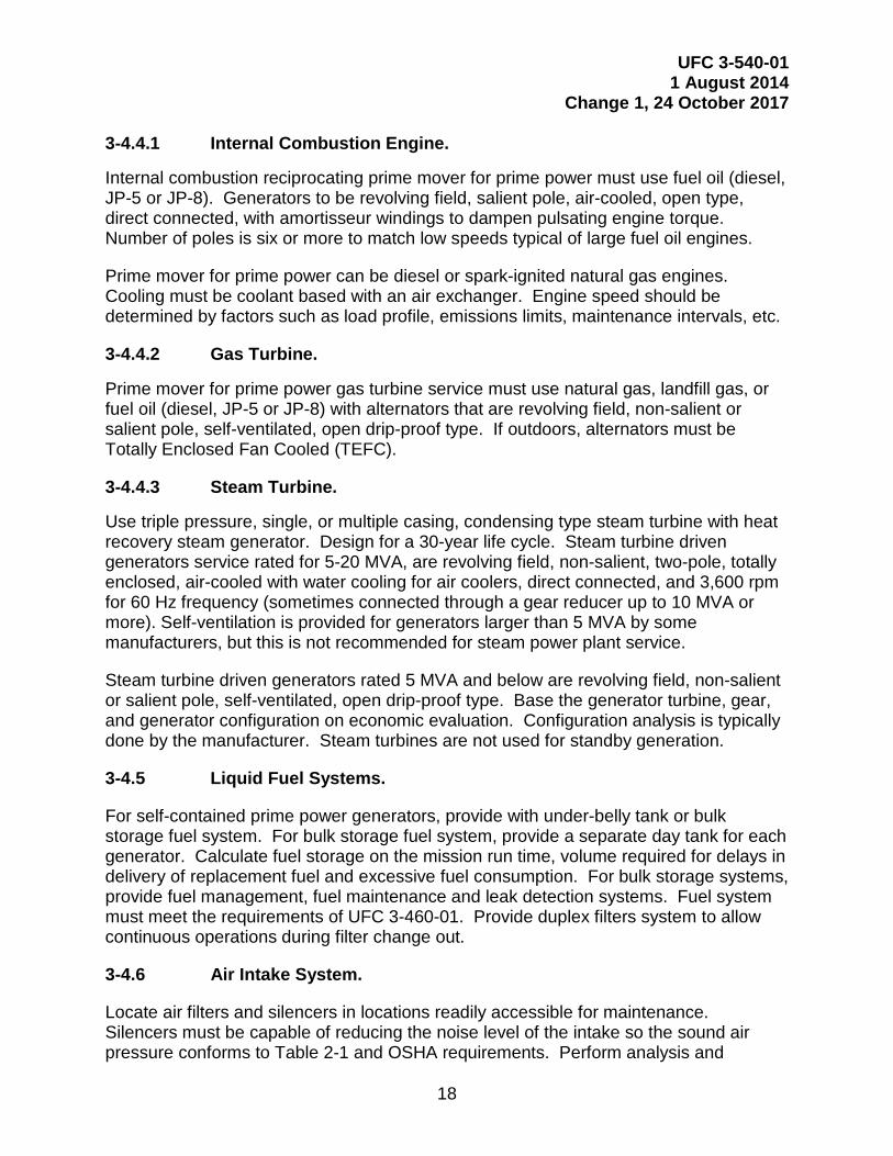
3-4.4.1 Internal Combustion Engine.
Internal combustion reciprocating prime mover for prime power must use fuel oil (diesel, JP-5 or JP-8). Generators to be revolving field, salient pole, air-cooled, open type, direct connected, with amortisseur windings to dampen pulsating engine torque. Number of poles is six or more to match low speeds typical of large fuel oil engines.
Prime mover for prime power can be diesel or spark-ignited natural gas engines. Cooling must be coolant based with an air exchanger. Engine speed should be determined by factors such as load profile, emissions limits, maintenance intervals, etc.
3-4.4.2 Gas Turbine.
Prime mover for prime power gas turbine service must use natural gas, landfill gas, or fuel oil (diesel, JP-5 or JP-8) with alternators that are revolving field, non-salient or salient pole, self-ventilated, open drip-proof type. If outdoors, alternators must be Totally Enclosed Fan Cooled (TEFC).
3-4.4.3 Steam Turbine.
Use triple pressure, single, or multiple casing, condensing type steam turbine with heat recovery steam generator. Design for a 30-year life cycle. Steam turbine driven generators service rated for 5-20 MVA, are revolving field, non-salient, two-pole, totally enclosed, air-cooled with water cooling for air coolers, direct connected, and 3,600 rpm for 60 Hz frequency (sometimes connected through a gear reducer up to 10 MVA or more). Self-ventilation is provided for generators larger than 5 MVA by some manufacturers, but this is not recommended for steam power plant service.
Steam turbine driven generators rated 5 MVA and below are revolving field, non-salient or salient pole, self-ventilated, open drip-proof type. Base the generator turbine, gear, and generator configuration on economic evaluation. Configuration analysis is typically done by the manufacturer. Steam turbines are not used for standby generation.
3-4.5 Liquid Fuel Systems.
For self-contained prime power generators, provide with under-belly tank or bulk storage fuel system. For bulk storage fuel system, provide a separate day tank for each generator. Calculate fuel storage on the mission run time, volume required for delays in delivery of replacement fuel and excessive fuel consumption. For bulk storage systems, provide fuel management, fuel maintenance and leak detection systems. Fuel system must meet the requirements of UFC 3-460-01. Provide duplex filters system to allow continuous operations during filter change out.
3-4.6 Air Intake System.
Locate air filters and silencers in locations readily accessible for maintenance. Silencers must be capable of reducing the noise level of the intake so the sound air pressure conforms to Table 2-1 and OSHA requirements. Perform analysis and

UFC 3-540-01 1 August 2014
Change 1, 24 October 2017
19
document in accordance with UFC 3-450-01. Filtration system must protect the safety of life and prevent harmful foreign material, including water, from entering the system. Configure filtration system to the operational environment providing anti-icing and water separators as appropriate.
3-4.7 Lubrication System.
Provide either wet sump or dry sump lubricating systems. Provide lubrication system, filtration, and cooler per manufacturer recommendations.
3-4.8 Cooling System.
For packaged or modular (example, packaged in ISO containers or weather resistant containers) reciprocating engine prime power systems (example, packaged in ISO containers or weather resistant containers), use self-contained, liquid to air cooled heat exchanger system or air-cooled system.
For all other systems, use closed-cycle wet cooling system.
3-4.9 Exhaust / Air Emissions Control System.
Exhaust / air emissions from prime power generators must comply with federal, state, local and host nation air quality rules and regulations. Comply with approved operating permits. Adding a Selective Catalytic Reduction (SCR) or other EPA mandated emission control devices to a prime power generator may adversely affect its operation. Prior to adding SCR or other EPA mandated emission control devices to a primer power generator, a thorough design review should be conducted and approved by the engine manufacturer prior to installation.
3-4.10 Starting System.
Mission requirements dictate reliability for starting systems. Select the starting system based upon mission requirements and life cycle cost analysis. Electric starters may be used for units up through 3 MW, if start times are met. Pneumatic starting may be used for units where a pneumatic system exists or the life cycle costs justify its use. For legally required or emergency stand-by generators, use electric starting systems.
3-4.11 Control System.
Provide generator and electrical system protection in accordance with IEEE Std 446 IEEE Recommended Practice for Emergency and Standby Power Systems for Industrial and Commercial Applications and IEEE Std. 242 Recommended Practice for Protection and Coordination of Industrial and Commercial Power Systems.
3-4.11.1 Industrial Control Systems (ICS).
Provide an ICS for electrical power generation control and protection, either analog, programmable logic controllers, microprocessor, or distributed control system (DCS) as

UFC 3-540-01 1 August 2014
Change 1, 24 October 2017
20
required by the sophistication required for operation of the generating units and associated systems.
3-4.11.2 Supervisory Control and Data Acquisition (SCADA).
Provide a SCADA system as required by the sophistication required for operation of the generating units and associated subsystems and the needs for operator monitoring and control. Government will have a licensed copy of the required software and the right to operate changes in the controller’s settings.
Power plant control systems are operational technology that must be standalone and meet the requirements of DoD 8500.01 and NIST 800-82. NIST Special Publication 800-37 will be utilized during development of control system designs. Analog systems are only to be provided as a part of an existing analog system. No new or grass root systems are to be provided for new generators with analog controls. Controls and redundancy including a supporting network must be based upon need (criticality and RAM factors). Open communication protocols (MODBUS) to be deployed, to allow future interface and connection to other manufacturers.
3-4.11.3 Subsystems.
Provide management control stations at strategic points in the plan for maintenance and redundant control requirements. Provide automated subsystems for the following:
• Each engine-generator.
• Fuel system.
• Air Pollution Control Equipment.
• Electrical substation.
• Emergency shut down.
• Balance of plant controls.
3-4.11.4 Analog.
Analog control is only to be considered when matching to an existing system.
3-4.11.5 Microprocessor-Based Control Stations.
Use PLCs when fast response times are required, such as near real-time actions such as a safety shutdown or firing control. Provide a separate controller for safety systems. A PLC can handle only a few thousand Input / Output (I/O) points and are not easily scalable.
If redundancy is required, evaluate use of PLCs verses using a DCS.

UFC 3-540-01 1 August 2014
Change 1, 24 October 2017
21
3-4.11.6 Attributes.
The Control system must include the following information and abilities:
• Generator status information (for each generating unit).
• Running / not running.
• Lubricating oil pressure.
• Engine temperature.
• Starting system status (battery / pneumatic receiver status).
• Cooling system temperature.
• Starting aid status (jacket water / oil sump heater condition / temperature).
• Fuel system status information.
• Switchgear breaker control switches available to the operator.
• Pressure and temperature indications of the engine and exhaust.
• Vibration notification.
• Generator loading, voltage, frequency and current.
• Cooling water temperature.
• Automatic synchronization.
• Startup, shutdown and emergency shutdown capability.
• Non-resettable run time hours meter.
• Exhaust pressure and/or temperature indicators to track / monitor operation of air emissions controls systems for environmental compliance with site permit.
• Note: vibration monitoring is warranted on only limited applications and larger generator sizes.
3-4.11.7 Control Room.
The control room should be located in or close to the turbine / engine area to allow quick operational access. Provide a completely enclosed control room with sound attenuation, and air conditioned with high efficiency filtration. Mount instruments on a panel within the control room. Provide heating/cooling system to maintain positive pressure within the control room to keep dust and other dirt particles from entering.
The control room must have:
• Clean, dry atmosphere.
• Relatively constant temperature and humidity.

UFC 3-540-01 1 August 2014
Change 1, 24 October 2017
22
• No vibration.
• Adequate light.
• Reliable electric power, free of surges in voltage and frequency.
• Air conditioning (a necessity for electronic distributive control systems and computers).
• Direct visual (windows) or video surveillance of generators.
3-4.12 Direct Current (DC) Power System.
Prime generator sets under 2500 kVA may not need a 125 VDC battery system, as other reliable power may be available. Those units that are stand-alone or requiring a black-start must have a 125 or 250 VDC dual power system comprised of two battery banks, one being the redundant set, two battery chargers and inverters, racks, and circuit breaker distribution for powering switchgear protection and metering. In addition, provide a dual 24 VDC power system with a UPS for generator controls, safety and emergency systems. Configure the DC power systems in crosstie configurations and provide battery disconnecting means for safe battery maintenance. Stationary battery areas must comply with UFC 3-520-05.
3-4.13 Paralleling Switchgear.
Connect two or more generators and synchronize with respect to frequency, voltage, and phase angle using paralleling switchgear. This arrangement is suitable for paralleling switchgear operating at a voltage of 4.16 kV and up to approximately 10 MVA. For paralleling switchgear operating at 13.8 kV, this arrangement is the best for stations up to about 25 or 32 MVA.
For larger stations, the fault duty on the common bus reaches a level that requires more expensive feeder breakers, and the bus should be split. The bus and switchgear must be in the form of a factory fabricated metal clad switchgear. For plants with multiple generators and outgoing circuits, the bus must be split for reliability using a bus tie breaker to permit separation of approximately one-half of the generators and lines on each side of the split.
3-4.13.1 Integrated Paralleling Switchgear.
For permanent packaged or modular prime power plant configurations, pre-engineered integrated parallel switchgear may be used. Switchgear must provide automatic matching of on-line generators to loads. Provide with a dedicated controller and industrial graphical color HMI and include emergency stop buttons for each generator.
3-4.14 Distribution Switchgear.
If the plant is 20 MVA or larger, and the area covered by the distribution system requires distribution feeders in excess of two miles, it is cost advantageous to connect the

UFC 3-540-01 1 August 2014
Change 1, 24 October 2017
23
generators to a higher voltage bus and feed several distribution substations from that bus with step-down substation transformers at each distribution substation. Distribution switchgear must conform to UFC 3-520-01 and UFC 3-550-01.
Select the high voltage bus configuration for reliability and economy. Alternative bus arrangements include main and transfer bus, ring bus, and breaker and a half schemes. The main and transfer arrangement, is the lowest cost alternative but is subject to loss of all circuits due to a bus fault. The ring bus arrangement, costs only slightly more than the main and transfer bus arrangement and eliminates the possibility of losing all circuits from a bus fault, since each bus section is included in the protected area of its circuit. Normally, it will not be used with more than eight bus sections because of the possibility of simultaneous outages resulting in the bus being split into two parts. The breaker and a half arrangement, is the highest cost alternative and provides the highest reliability without limitation on the number of circuits.
The distribution selection is based upon criticality and reliability. Normal configuration for prime power generators is a two-bus, an A and B bus, system.
3-4.15 Split Bus.
A split bus panelboard is one where there are two separate portions of bus, one on top and the other on the bottom. The bottom bus may be sub-fed, or may be completely separate. The primary reason for this separation is to identify those items that must be fed by a generator, and the others may be switched off during a utility outage. This configuration is not recommended due to the possibility of someone assuming that the entire panel is off when in actuality it is not.
However, in controlled circumstances, where the labelling is done correctly, and the identification is correct, this methodology can be used to handle identification of loads requiring standby. This would occur in locations such as dining facilities (DFAC), where refrigerators and freezers require generator power, while room receptacles and auxiliary lighting do not require standby power. The preferred method is using separate panelboards for critical and non-critical loads. Refer to UFC 3-540-07 for additional guidance.
3-4.16 Black Start Generator.
For power plants with generators that cannot start without utility power, provide a self- contained engine generator that allows the power plant to recover from a total or partial shutdown and allows the individual generators to start from a completely dead or inactive state. Size battery system to have the capability in reserve power for a minimum of three firing attempts.
3-4.17 Communications and Alarms.
Communications systems are to conform to UFC 3-580-01. Communication must allow operators to monitor generator loading and provide an alarm when the generator is near overload, or in overload condition.

UFC 3-540-01 1 August 2014
Change 1, 24 October 2017
24
Alarms must encompass oil levels, fuel levels and flow, vibration, generator temperature, emissions, electrical system monitoring, relay systems and first out and subsequent trip list. Incorporate applicable NFPA 110 alarms.
3-5 ENVIRONMENTAL.
Comply with Para. 2-4.2.
3-6 COMMISSIONING.
The purpose of commissioning is to make sure all parts of the generation system perform as designed and function properly according to the manufacturer’s recommendations. Commissioning must be performed with a disruption of incoming power upstream of the incoming service. At the end of design, if a generator is de-rated for any reason it shall be documented in the O&M manuals and labelled appropriately.
The systems to be commissioned are:
• Generator.
• Prime mover.
• Controls.
• Battery system.
• Switches.
• Fuel system.
• Load system transfer (ATS or switchgear).
• Grounding.
3-7 GENERATOR PLANT SECURITY.
Provide plants and facilities with security and protection against possible harmful events. Refer to UFC 4-010-01 for security requirements in buildings and facilities. /1/

UFC 3-540-01 1 August 2014
Change 1, 24 October 2017
25
APPENDIX A REFERENCES
Note: The most recent edition of referenced publications applies, unless otherwise specified.
UNIFIED FACILITIES CRITERIA
https://www.wbdg.org/ffc/federal-facility-criteria
UFC 1-200-01, Building Code (General Building Requirements)
UFC 3-460-01, Design: Petroleum Fuel Facilities
UFC 3-501-01, Electrical Engineering
UFC 3-520-01, Interior Electrical Systems
UFC 3-540-07, Operations and Maintenance Generators
UFC 4-510-01, Design: Medical Military Facilities
AMERICAN NATIONAL STANDARDS INSTITUTE
https://webstore.ansi.org/sdo.aspx
C50.10, General Requirements for Synchronous Machines
C50.13, Cylindrical-Rotor 50 Hz and 60 Hz Synchronous Generators Rated 10 MVA and Above
C50.14, Requirements for Combustion Gas Turbine Driven Cylindrical Rotor Synchronous Generators
ELECTRICAL GENERATING SYSTEMS ASSOCIATION
http://www.egsa.org/
EGSA - 101P, Engine Driven Generating Sets Performance Standard
IEEE (FORMERLY INSTITUTE OF ELECTRICAL AND ELECTRONICS ENGINEERS)
https://www.ieee.org/publications_standards/index.html
IEEE Std. 242-2001, IEEE Recommended Practice for Protection and Coordination of Industrial and Commercial Power Systems
IEEE Std 446-1995 (R 2000), Recommended Practice for Emergency and Standby Power Systems for Industrial and Commercial Applications (IEEE Orange Book)

UFC 3-540-01 1 August 2014
Change 1, 24 October 2017
26
IEEE Std 3006, Power Systems Reliability
INTERNATIONAL ORGANIZATION FOR STANDARDIZATION
http://www.iso.org/iso/home/store/catalogue_ics.htm
ISO 8528-1:2005, Reciprocating internal combustion engine driven alternating current generating sets — Part 1: Application, ratings and performance
ISO 8528-5:2013, Reciprocating internal combustion engine driven alternating current generating sets - Part 5: Generating sets
NATIONAL ELECTRICAL MANUFACTURERS ASSOCIATION
http://www.nema.org/Standards/pages/default.aspx
SM 23, Steam Turbines for Mechanical Drive Service
SM 24, Land Based Steam Turbine Generator Sets 0 to 33 MW
NATIONAL FIRE PROTECTION ASSOCIATION
http://www.nfpa.org/codes-and-standards
NFPA 30-2012, Flammable and Combustible Liquids Code
NFPA 37-2010 (Through AMD 3), Standard for the Installation and Use of Stationary Combustions Engines and Gas Turbines
NFPA 70-2014, National Electrical Code
NFPA 99-2012, Health Care Facilities
NFPA 110-2013 (Through AMD 5), Emergency and Standby Power Systems
NATIONAL INSTITUTE OF STANDARDS AND TECHNOLOGY
https://www.nist.gov/srm
nvlpubs.nist.gov/nistpubs/SpecialPublications/NIST.SP.260-176.pdf
NIST Special Publication 800-27, Guide for Applying the Risk Management Framework to Federal Information Systems.
NIST Special Publication 800-82, Guide to Industrial Control Systems (ICS) Security
OCCUPATIONAL SAFETY AND HEALTH ADMINISTRATION
https://www.osha.gov/law-regs.html

UFC 3-540-01 1 August 2014
Change 1, 24 October 2017
27
UNDERWRITERS LABORATORIES
http://ulstandards.ul.com/access-standards/
UL 1008-2012 (Reprint Aug 2013), Automatic Transfer Equipment

UFC 3-540-01 1 August 2014
Change 1, 24 October 2017
28
This Page Intentionally Left Blank

UFC 3-540-01 1 August 2014
Change 1, 24 October 2017
29
APPENDIX B EXAMPLES
Appendix B provides examples and simple depictions of different configurations.
B-1 SINGLE GENERATOR SYSTEM CONFIGURATIONS.
B-1.1 Single Engine Generator Supply to Essential Loads.
If the facility has a permanently installed emergency power source, provide a separate panel to supply only the loads requiring emergency power. This panel will normally be supplied by the upstream main distribution panel. Figure B-1 provides an example of this configuration.
Figure B-1 Typical Single Engine Generator Configuration
* Note that the circuit breaker shown on the generator can be located on the generator skid, in a separate enclosure mounted adjacent to the ATS, or integral with the ATS.
B-1.2 Permanently Installed Engine Generator with Portable Connection.
If the facility is designed with a permanently installed generator and a connection for a portable generator, do not connect the conductors for both generators directly onto the emergency side of the associated ATS. Install a double-throw switch upstream of the ATS; connect the permanently installed generator and the portable generator connection to this double-throw switch, with the output of the switch connected to the ATS. Figure B-2 provides an example.

UFC 3-540-01 1 August 2014
Change 1, 24 October 2017
30
Figure B-2 Configuration for Permanently Installed and Portable Generator
B-1.3 Single Engine Generator Configuration for Whole Building Supply.
If the engine generator is designed to supply the entire facility, provide circuit breakers on each supply to the ATS as shown in Figure B-3.

UFC 3-540-01 1 August 2014
Change 1, 24 October 2017
31
Figure B-3 Whole Building Generator Supply Configuration
B-1.4 Single Engine Generator Configuration with Multiple ATS.
If the engine generator supplies more than one ATS, install an emergency distribution panelboard or switchboard as shown in Figure B-4.

UFC 3-540-01 1 August 2014
Change 1, 24 October 2017
32
Figure B-4 Configuration to Supply Multiple ATS
B-1.5 Single Engine Generator with Redundant Utility Supply.
If redundant utility sources are available, design the system to select either normal utility source with the generator as a standby if both utility sources fail. Figure B-5 provides an example.

UFC 3-540-01 1 August 2014
Change 1, 24 October 2017
33
Figure B-5 Selection Between Redundant Utility Supply and Generator
B-1.6 Dual Engine Generator with Redundant Utility Supply.
If redundant utility sources are available, design the system to select either normal utility source with the generator as a standby if both utility sources fail. If dual rather than parallel generators are provided, use an ATS to select between the generator supplies also. Figure B-6 provides an example.

UFC 3-540-01 1 August 2014
Change 1, 24 October 2017
34
Figure B-6 Selection Between Redundant Utility Supply and Dual Generators
B-2 PARALLEL GENERATOR SYSTEM CONFIGURATIONS.
B-2.1 Utility Supply.
Parallel generators require the use of paralleling switchgear that results in a more complex operating system. Determine if a single utility supply (Figure B-7) satisfies reliability requirements. If additional system reliability is required, install an alternate commercial power supply as shown in Figure B-8. If feasible for the commercial power distribution system design, provide an alternate commercial power supply from a different source than the normal supply. Figure B-9 shows the preferred configuration if UPS systems are also supplied by alternate commercial and emergency power.
Figure B-7 Parallel Generators with Single Utility Supply

UFC 3-540-01 1 August 2014
Change 1, 24 October 2017
35
Figure B-8 Parallel Generators with Alternate Utility Supply
Figure B-9 Parallel Generators with Alternate Utility Supply for UPS Systems
B-2.2 Parallel Generator Control Systems.
Provide a redundant system in which any control system display can operate the control system. Design redundant PLCs for system control. A properly designed system can withstand a single failure and still operate. Figure B-10 shows an example of the control system architecture.

UFC 3-540-01 1 August 2014
Change 1, 24 October 2017
36
Figure B-10 Parallel Generator Control System Architecture
B-3 AUTOMATIC TRANSFER SWITCH CONFIGURATIONS.
Figure B-11 shows a simplified configuration with a four-pole ATS. For purposes of comparison, Figure B-12 shows a simplified configuration with a three-pole ATS.
Figure B-11 Typical Four-Pole ATS Arrangement

UFC 3-540-01 1 August 2014
Change 1, 24 October 2017
37
Figure B-12 Typical Three Pole ATS Arrangement

UFC 3-540-01 1 August 2014
Change 1, 24 October 2017
38
This page intentionally left blank.

UFC 3-540-01 1 August 2014
Change 1, 24 October 2017
39
APPENDIX C CHECKLIST
This appendix provides a design checklist of items to consider or address as part of the system design.
C-1 GENERAL.
A. Physical Space Requirements
1. Engine-generator dimensions. 2. Operation and maintenance space. 3. Cooling system space. 4. Fuel system space. 5. Ventilation (cooling air intake and exhaust). 6. Electrical panels, transfer switches, control panel spaces. 7. Exhaust system space and silencer location. 8. Starting system (electrical / air start). 9. Draw-out equipment requirements.
B. Power Rating – Continuous, prime, limited time running power, or emergency standby power.
C. Maximum time to start and be ready to assume load
(Emergency application consequences).
D. Emissions
1. Exhaust gas composition and particulate limits. 2. Noise limits. 3. Thermal emissions (air/water). 4. Fuel system constraints.
E. Generator Paralleling
1. Define sources. 2. Define configuration. Provide single-line diagram with the 35% design
submittal.
C-2 ELECTRICAL.
A. Generator Sizing
1. Electrical load (kVA) – facility loads plus loads for fans, fuel pumps, lighting, battery charging, etc.
2. Motor starting kVA. 3. Nonlinear loads and effect on generator rating. 4. Power factor.

UFC 3-540-01 1 August 2014
Change 1, 24 October 2017
40
5. Engine-generator application – single set / parallel. 6. Frequency bandwidth (steady state). 7. Frequency regulation maximum – no load to full load. 8. Voltage regulation – no load to full load. 9. Voltage bandwidth – steady state. 10. Frequency – 50 / 60 Hz. 11. Voltage – output volts. 12. Phases – 3 phase, wye / delta, single phase. 13. Max step load increase – kVA. 14. Transient recovery time – seconds (voltage and frequency). 15. Maximum voltage deviation (transient). 16. Maximum frequency deviation – hertz. 17. Convenience duplex receptacles in generator room (for tools, testing,
house-keeping).
B. Generator Protection
1. Subtransient reactance – percent (minimum). 2. Switchgear / breaker size, location, characteristics, enclosure. 3. Parallel generators – current transformers installed on neutral side of
generator windings.
C. Automatic Transfer Switch
1. Sizing, controls, transfer options. 2. Coordination of ground fault protection (four-pole / three pole). 3. In-phase protection for large motors downstream of transfer switch. 4. Define sequence of operation “Upon loss of normal power...”. Define
load shedding, motor starting sequence, if required, multiple generator operation, method of return to normal power (time delays), etc.
D. Starting System (Electric-Start)
1. Battery location – on skid. 2. Battery charger location. 3. Circuit size and routing. 4. Ventilation for battery charging. 5. Battery temperature limitations.
E. Starting System Controls
F. Generator Controls
G. Additional Circuits – coolant pumps, fuel transfer pumps, engine heaters, fuel heaters, piping heat-trace, cathodic protection, etc.
H. Grounding

UFC 3-540-01 1 August 2014
Change 1, 24 October 2017
41
1. Generator grounding - ungrounded, solidly-grounded, impedance-grounded.
2. Equipment grounding. 3. Building grounding and connections. 4. Surge arrester grounding.
I. Lighting
1. Equipment room normal lighting. 2. Equipment room alternate-source lighting. 3. Equipment room emergency lighting. 4. Outdoor enclosure lighting (access for controls).
J. Electrical Connections
1. Connections with strain relief on power and communication connections to generator circuit breakers.
K. Load bank requirements for future testing.
L. Safety
1. Arc flash analysis and warning labels. 2. Posting of applicable safety signage based on expected hazards (i.e.
Personal Protective Equipment Signage, High Voltage, etc.). 3. Automatic External Defibrillators (AEDs) may be warranted if medical
assistance is unable to respond within 4 minutes. 4. Enclosure of electrical hazards. 5. Posting of applicable safety signage based on expected hazards (i.e.
Noise Hazard, etc.)
C-3 MECHANICAL.
Evaluate system for compliance with NFPA 30, 37, and 110.
A. Engine
1. Installation elevation above sea level (derating). 2. Maximum speed (900 / 1200 / 1800 rpm). 3. Fuel consumption. 4. Starting system (air-start). 5. Ambient temperature extremes (HVAC, and / or derating). 6. Vibration limitations. 7. Ancillary equipment.

UFC 3-540-01 1 August 2014
Change 1, 24 October 2017
42
B. Fuel System
1. Main fuel tank (location, fill point, environmental requirements, cathodic protection) – UFC 3-460-01.
2. Day tank (space, location, shape, venting, NFPA 30 – capacity constraints, elevation relative to fuel injectors).
3. Fuel level controls. 4. Fuel transfer pump. 5. Supply line / return line routing. 6. Fuel coolers. 7. Fuel heaters.
C. Lube-Oil System
1. Integral to engine. 2. External to engine. 3. Space and provision for changing the oil.
D. Governor
1. Type: droop or isochronous. 2. Frequency bandwidth (steady state). 3. Frequency regulation maximum – No load to Full Load.
E. Engine Cooling
1. Heat exchanger location (local / remote). 2. Cooling system design:
a. Local – Usually unit mounted radiator ducted through wall. b. Remote heat exchanger – Usually requires expansion tank,
pumps, piping, local heat exchanger, remote heat exchanger (radiator, cooling tower, etc.).
3. Maximum summer outdoor temperature (ambient). 4. Minimum winter outdoor temperature (ambient). 5. Cooling medium (glycol / water, raw water, etc.).
F. Engine Room Ventilation
1. Cooling - Maximum allowable heat transferred to engine generator space at rated output capacity.
2. Maximum summer indoor temperature (prior to generator operation). 3. Minimum winter indoor temperature (prior to generator operation). 4. Combustion air source (separate from cooling system).
G. Engine Controls (NFPA 37).
H. Exhaust System

UFC 3-540-01 1 August 2014
Change 1, 24 October 2017
43
1. Insulated / non-insulated). 2. Silencer (muffler location – inside /outside). 3. Penetration (roof/wall, location, thimble detail). 4. Multiple generating units - common exhaust considerations. 5. Exhaust considerations: flappers, gooseneck, bird-screen, rain shields.
I. Sound Limitations (OSHA, State, City Ordinances, Post / Base regulations)
1. Mechanical noise mitigation (interior/exterior). 2. Combustion-air intake noise mitigation (interior / exterior). 3. Exhaust noise mitigation (exterior). 4. Posting of signage - Hearing Protection Required.
J. Safety
1. Guarding of mechanical hazards. 2. Insulation of hot equipment. 3. Enclosure of electrical hazards. 4. Posting of signage for equipment which may auto-start. 5. Posting of applicable safety signage based on expected hazards (i.e.
Noise Hazard, etc.).
C-4 CIVIL / STRUCTURAL.
A. Seismic zone design.
B. Vibration isolation.
C. Foundation, house-keeping pads, etc.
D. Grading, fuel tank installation.
C-5 ARCHITECTURAL.
A. Building design, louvers, doors, etc.
B. Bird screens for penetrations.
C. Enclosure type – corrosion and high humidity location, desert environment.

UFC 3-540-01 1 August 2014
Change 1, 24 October 2017
44
This page intentionally left blank.

UFC 3-540-01 1 August 2014
Change 1, 24 October 2017
45
APPENDIX D GENERATOR SIZING
Appendix D discusses the input data required as part of a generator sizing calculation.
D-1 LOAD EVALUATION.
When specifying engine-generator sets, the designer will analyze the load characteristics and profiles of the load to be served to determine the peak demand, maximum step load increase and decrease, motor starting requirements (represented as starting kVA), continuous and non-continuous loads (cyclical / periodic), and the non-linear loads to be placed on the engine generator set. This information represents the essential elements that determine generator capacity and controls requirements. Engine generator set configuration is determined to some degree by characterization of the loads to be served and the interaction of that load with the engine generator set. Size, speed, allowable alternator temperature rise, and generator controls are all greatly affected by the character of the load to be served, and any of the above factors may determine generator sizing.
D-1.1 Uninterruptible, Essential, and Nonessential Loads.
As part of the standby power load analysis, classify each load as to the type of power that it should have. Determine which loads within the facility need to continue to function following a loss of normal power. Evaluate which loads must be uninterruptible, those to which power must be restored to perform an essential function (essential), or are not required for the facility/mission to function if the normal power source is interrupted (non-essential).
• Uninterruptible – loads in this category require continuous power and cannot experience even momentary power disruptions. Loads in this category usually involve life safety or include hazardous or industrial process equipment, command, control, computer, data center, and communications systems. These loads will usually require the use of battery standby or an uninterruptible power system (UPS) to power them until supplied with power from an engine generator system.
• Essential – loads in this category require standby power, but can be de-energized until they can be supplied from an engine generator system. Loads in this category usually include HVAC loads to vital facilities or other load types that can be de-energized for short periods without severe consequence.
• Nonessential – loads in this category can be de-energized for extended periods without severe consequence. Although these loads might be classified as nonessential, they might still be capable of being energized from engine generators, depending on the facility design. For most systems, nonessential loads do not require generator standby.

UFC 3-540-01 1 August 2014
Change 1, 24 October 2017
46
D-1.2 Conditions of Loading.
Peak demand calculation provides one factor that determines the alternator size. Peak demand is the sum of continuous loads and non-continuous loads that are likely to be coincident.
• Continuous loads are energized for periods greater than 3 hours, such as lighting, UPS systems, and some HVAC equipment.
• Non-continuous loads do not meet the definition of continuous and the proportion of on to off time varies with each load.
• Coincident loads are those that are not prevented by character or controls from being energized at the same time.
• Non-coincident loads are dissimilar loads, fed from a common source that are prevented by character or controls from being energized at the same time. An example of a non-coincident load might be all compressors on an air conditioning chiller that are sequenced by a control system such that they do not operate simultaneously.
D-1.3 Nonlinear Loads.
Identify loads that are nonlinear. Non-linear loads are loads that draw a non-sinusoidal current waveform when supplied by a sinusoidal voltage source. Typical non-linear loads include solid state switching power supplies, computer power supplies (including those found in desktop PC’s, uninterruptible power supplies, variable frequency drives, radar power supplies, and solid state ballasts in fluorescent light fixtures. These loads cause distortion of the source voltage and current waveforms that can have harmful effects on many types of electrical equipment and electronics, including generators. A low generator sub-transient reactance minimizes the voltage waveform distortion in the presence of such loads. For this reason, when the non-linear loads comprise 25% or more of the loads served, the generator sub-transient reactance should be limited to no more than 0.12.
Provide the assessment of the proportion of linear versus nonlinear loads to the generator supplier. Depending on the proportion of nonlinear loads, the generator supplier might recommend oversizing the generator, might modify the generator control system, or provide a generator with a lower sub-transient reactance.
D-1.4 Step Loading.
Step load increase / decrease is used to account for the addition or loss of significant blocks of load. The significance of this is that the generator must be sized and controlled to maintain voltage and frequency within specific limits after sudden acquisition/loss of load (described as transient response). Establish the step loads that will be applied to or removed from the generator after startup. Some systems might apply all loads in a single step and other systems might establish multiple steps in order to limit the voltage and frequency transient during generator loading / unloading.

UFC 3-540-01 1 August 2014
Change 1, 24 October 2017
47
If the calculated generator size is based on transient response capability (control of voltage or frequency excursion from rated value) rather than peak load, consider load steps to reduce the amount of loads acquired at any single instant. Consider the following as part of the load analysis:
• Smaller generator systems will usually have a single automatic transfer switch (ATS) and all required loads will be energized at the same time.
• Larger generator systems might have multiple ATS, which can allow staggering of the load with discrete load steps.
• Some connected loads can have restart time delays independent of any ATS time delay.
• Parallel generator systems will usually have multiple ATS or distribution circuit breakers in the paralleling switchgear to establish step loading time delays.
D-1.5 Motor Starting Requirements.
Motor starting requirements are important to properly size engine generator sets because the starting current (inrush) for motors can be as much as six times the running current, and can cause generator output voltage and frequency to drop, even though the generator system has been sized to carry the running load. The designer must analyze the motor loads to determine if the starting characteristics of a motor or a group of motors to be started simultaneously will result in inadequate system performance.
Provide a motor starting kVA value for the largest motor or combination of motors to be started simultaneously. An increase in the size rating of the engine generator may be necessary to compensate for the inrush current. This information assists the engine generator supplier in properly sizing the engine generator set.
D-2 GENERATOR RATING.
The generator rating depends on the load analysis results, the projected annual and continuous run-time, and the overall system design and configuration.
D-2.1 Industry Ratings.
The generators addressed by this UFC will normally be rated based on their limited time running power classification (EGSA 101P, ISO 8528-1), which engine-generator manufacturers often refer to as the standby rating.
Apply the generator prime power rating for the installation if any of the following conditions apply:
• The expected annual operating time is longer than stated above, which might occur if the system will be used for utility peak shaving.

UFC 3-540-01 1 August 2014
Change 1, 24 October 2017
48
• The generator will be operating at near 100 percent of rating and the load is nonvarying. Note: Historical experience indicates that most diesel generators will rarely be loaded near 100 percent and less than 50 percent loading is common.
• The system is designated as a Critical Operations Power System (COPS) in accordance with NFPA 70 Article 708.
D-2.2 Generator Capacity Rating.
The required generator capacity depends on:
• Load analysis results; refer to paragraph D-1.1. Size the generator based on expected power demand rather than connected load.
• Magnitude of load steps that will be applied to the generator, together with the desired transient response characteristics.
• Allowable voltage and frequency variation, including initial loading effect.
• Oversizing to mitigate the effects of nonlinear loads. Note: For combinations of linear and non-linear loads where the percentage of non-linear loads is small relative to the capacity rating of the generator (25% or less), standard generator configurations are normally acceptable.
Small generators with a relatively simple load analysis can be sized by hand calculations. Larger generator systems with a large proportion of nonlinear loads or multiple load steps will require software specifically designed for generator sizing. Generator suppliers can provide this software or will perform the calculations.
D-2.3 Uninterruptible Power Supply (UPS) Systems.
UPS systems can have a detrimental effect on generator control systems and need to be considered in the generator performance requirements and generator commissioning. Ensure the following are addressed in the design:
• Generator and UPS communication so that the UPS recognizes when it is operating on a generator.
• Allowed battery charging current while the UPS operates on a generator source. UPS battery charging is not considered a critical / mission-essential load during generator operation and should be reduced to the minimum allowed by the UPS design, if it is an available UPS design feature.
• Power walk-in – limit the rate at which the UPS transfers from its internal battery to the generator, if available in the UPS design.
• UPS input filter energized only after adequate load is established. Generator sets inherently have difficulty controlling voltage with leading power factors, which can cause an increasing voltage as the voltage

UFC 3-540-01 1 August 2014
Change 1, 24 October 2017
49
regulator attempts to control voltage. This condition can be exacerbated during UPS start-up by the power walk-in feature. Typically, a UPS has some means of gradually applying load to the source over a 3 to 60 second period. An unloaded input filter may cause a leading capacitive power factor load beyond the generator’s voltage control ability. Other loads connected to the generator will counter this effect. Disconnecting the filter at lower UPS loads will minimize this effect. This is an essential design requirement.
• Rotary UPS on DC bus – limit the rotary recharge rate when the UPS is operating on generator.
• If the system has step loading capability, energize nonlinear loads such as a UPS after other mechanical-type loads have been energized.
Ensure the engine generator commissioning process confirms acceptable operation of the fully connected system with the UPS systems in service.
D-2.4 Power Quality.
The load analysis described in paragraph D-1 requires an assessment of the proportion of linear versus nonlinear loads. Nonlinear loads can adversely affect the generator control system. Provide this information to the generator supplier for evaluation.
Ensure the engine generator commissioning process confirms acceptable operation of the fully connected system with the nonlinear loads in service. If power factor correction capacitors are installed, ensure they are energized during the commissioning process if they are to remain in service.

UFC 3-540-01 1 August 2014
Change 1, 24 October 2017
50
This Page Intentionally Left Blank

UFC 3-540-01 1 August 2014
Change 1, 24 October 2017
51
APPENDIX E CONNECTION METHODS FOR PORTABLE GENERATORS
E-1 INTRODUCTION.
This appendix provides information regarding the use of NFPA 70, UL-listed, CSA-certified, double-locking, single pole connectors (Cam-Lok style) or MIL C-22992, Class L, QWLD-rated multiple cylindrical pin connectors (Cannon plug) as quick connection / disconnection means for portable generator connections of 600 volts or less for facilities. This is the typical Air Force connection method for portable generators.
Portable generators are referred to as standby generators within the Air Force and are classified as EAID generators.
E-2 CONNECTION METHODS.
Generator facility connections must either be hardwired or utilize connection methods as noted below.
E-2.1 MIL-C-22992, Class L, QWLD-Rated Connectors.
Heavy-duty cylindrical, MIL-C-22992, Class L, QWLD-rated connectors (Cannon plug) with appropriately rated disconnect switch selected in accordance with NFPA 70 are permitted as follows:
• Up to three (3) connections per generator are permitted. The maximum single connector rating must be 200 amperes. Mobile Electric Power (MEP) 6 / 806 units are permitted to utilize a single 200A Cannon plug connection.
• The combined loads from multiple connections must not exceed the rated capacity of the standby generator.
• The single conductor size used in any connector must not exceed #4/0 American Wire Gauge (AWG).
• Unused connector receptacles must be capped with manufacturer-recommended covers to prevent exposure to live electrical contacts. Plastic dust caps are not acceptable.
• A data plate style placard must be permanently attached, using sheet metal screws or rivets, adjacent to the connection(s), which reads:
DANGER UNUSED CONNECTOR RECEPTACLES ARE ENERGIZED DURING
GENERATOR OPERATION. EXERCISE EXTREME CAUTION.
PROPER PPE REQUIRED WHEN MAKING CONNECTIONS
• Cable assemblies connected in parallel must comply with all of the following:

UFC 3-540-01 1 August 2014
Change 1, 24 October 2017
52
• Be the same length.
• Have the same conductor material.
• Be the same size in circular mil area.
• Have the same insulation type, including cable assembly sheathing.
• Be terminated in the same manner and be of the same rating. For example, a 200-ampere connection cannot be paralleled with a 60-ampere connection even though the cable assemblies are rated for 200 amperes.
• All operators must be trained on the danger associated with multiple connections on the generator bulkhead. Supervisors must document this training.
E-2.2 Single-Pole (Cam-Lok style) Connectors.
Single-pole (Cam-Lok style) connectors and receptacles that are double locking in accordance with the NEC and NEMA 3R rated are permitted with limitations. For standby generators, paralleled connections are prohibited. A single connector per phase must be used for each load and meet the following requirements (Note: MEP 6/806 units are permitted to utilize a single 200-ampere Cam-Lok style connector / plug connection per phase.):
• Connectors and receptacles must be rated 200 amperes or less, UL listed and CSA certified.
• Connector and receptacle contacts must be made of high-conductivity copper base alloy.
• Connector and receptacle must provide a double-locking means to ensure a minimum 600 lb/in2 pressure on contact.
• Connector contacts must be recessed. A thermoplastic rubber or neoprene-insulated jacket must extend past the ends of both the male and female contacts and meet the strain relief requirements listed below.
• Receptacles must be provided with NEMA 3R color-coded (for phase and ground identification) snap-back covers (150 amperes and less) or protective caps.
• Cable plugs must be provided with color-coded (for phase and ground identification) protective caps with lanyards.
• Tapping tees are not permitted.
• Connectors and cable plugs must be fully rated for intended use.
• Cable-to-plug connections must be crimped. Set-screw connection means are not allowed because of their tendency to loosen due to heating / cooling, high load, and vibration.

UFC 3-540-01 1 August 2014
Change 1, 24 October 2017
53
• The only approved cable strain relief means is vulcanized style terminations.
Up to three (3) Cam-Lok style connectors (max twelve [12] single-phase connectors) per generator are permitted to allow connection to three separate loads. The maximum single connector rating must be less than 200 amperes.

UFC 3-540-01 1 August 2014
Change 1, 24 October 2017
54
This Page Intentionally Left Blank

UFC 3-540-01 1 August 2014
Change 1, 24 October 2017
55
APPENDIX F FACILITY DESIGN TYPES
Appendix F discusses different facility design types that might be authorized to have a standby power system.
For Army applications, each major command / program defines its standby and emergency power requirements based on mission requirements, location / environmental parameters, and the NFPA criteria (life-safety). Typical applications that require standby or emergency power include: Command, Control, Communications, Computers (Data Centers), health care, industrial process facilities, RDT&E Facilities, Laboratories, and Installation Critical Support Services (including force protection, readiness, community support).
For Navy applications, Table F-1 provides a list of the types of facilities that are typically authorized to have emergency generators. This information was obtained from UFC-000-05N, Facility Planning for Navy and Marine Corps Shore Installations, and is not considered a complete list; it only contains the occurrences in UFC-000-05N where generators are mentioned.
For various Tri-Service applications, Table F-2 provides a summary of facilities that are authorized to have emergency power. This information was obtained from UFCs.

UFC 3-540-01 1 December 2016
56
Table F-1 Naval Facilities Authorized for Standby Power
Category Code Facility Type Comments
12330 Vehicle and Equipment Ready Fuel Storage
Authorized for buildings and utilities that may be needed in a hurricane or other base emergency.
13120 Communications Relay Facility Contains rack mounted communications receiving, amplification, and transmitting equipment, along with an Uninterruptible Power Source (UPS) and an Emergency Generator.
13122 VHF / UHF Communications Facility Contains a small UPS and an emergency generator. 13135 Receiver Building Contains a UPS and an emergency generator. 13140 Telephone Exchange Building Can contain the telephone switch, main distribution frame, intermediate
distribution frame, staff support spaces, operators work positions, maintenance and storage spaces, and is supported by UPS and emergency generators.
13150 Transmitter Building Contains a UPS and an emergency generator. 13372 Military Terminal Radar Approach
Control Facility Space is provided in the mechanical room for an emergency generator and UPS system.
13373 Fleet Area Control Surveillance Facility
The mechanical space should include sufficient room for as emergency generator and a UPS system.
13374 Joint Control Facility The mechanical spaces should include sufficient space for an emergency generator and UPS system.
13375 Air Surveillance Radar (ASR) Facility
The building and its associated antenna tower are located in a remote area of the airfield and an access road and emergency generator are required.
14365 Operations Control Center UPS and emergency generators are required for continuous operation during natural disasters and increased security postures.

UFC 3-540-01 1 December 2016
57
Category Code Facility Type Comments
14380 Command, Control, Communications, Computers, and Intelligence Facility (C4I)
The technical and operational mission of a C4I will require that it contain, Secure Compartmented Information Facility (SCIF) areas, a UPS, emergency generators, and in selected cases, Radio Frequency Interference (RFI) shielding, Electromagnetic Interference (EMI) shielding, and Telecommunications Electronics Material Protected from Emanating Spurious Transmissions (TEMPEST) protection.
14385 Joint Reserve Intelligence Center (JRIC)
The technical and operational mission of a JRIC will require that it contain, SCIF areas, a UPS, emergency generator(s), and in selected cases, RFI shielding, EMI shielding, and TEMPEST protection.
51010 Hospital Stand-by / emergency electrical generation, operational fuel storage of the generators or building heat systems and electrical transformers in direct support of the medical facilities should have the BUMED activity as the User and Maintenance UIC. The BUMED facility is not a complete and useable facility without the inclusion of these directly supporting utility systems.
81159 Standby Generator Building Standby generators are used to provide electrical power when the normal source of power is not available. This category includes all necessary equipment for the production of the commodity, including tanks, pumps, electrical equipment, and all other equipment for electrical generation.
81160 Standby Generator Plant Standby generators are used to provide electrical power when the normal source of power is not available. This category includes all necessary equipment for the production of the commodity, including tanks, pumps, electrical equipment, and all other equipment for electrical generation.
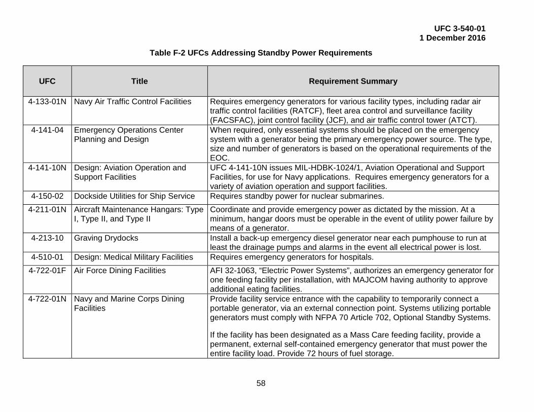
UFC 3-540-01 1 December 2016
58
Table F-2 UFCs Addressing Standby Power Requirements
UFC Title Requirement Summary
4-133-01N Navy Air Traffic Control Facilities Requires emergency generators for various facility types, including radar air traffic control facilities (RATCF), fleet area control and surveillance facility (FACSFAC), joint control facility (JCF), and air traffic control tower (ATCT).
4-141-04 Emergency Operations Center Planning and Design
When required, only essential systems should be placed on the emergency system with a generator being the primary emergency power source. The type, size and number of generators is based on the operational requirements of the EOC.
4-141-10N Design: Aviation Operation and Support Facilities
UFC 4-141-10N issues MIL-HDBK-1024/1, Aviation Operational and Support Facilities, for use for Navy applications. Requires emergency generators for a variety of aviation operation and support facilities.
4-150-02 Dockside Utilities for Ship Service Requires standby power for nuclear submarines. 4-211-01N Aircraft Maintenance Hangars: Type
I, Type II, and Type II Coordinate and provide emergency power as dictated by the mission. At a minimum, hangar doors must be operable in the event of utility power failure by means of a generator.
4-213-10 Graving Drydocks Install a back-up emergency diesel generator near each pumphouse to run at least the drainage pumps and alarms in the event all electrical power is lost.
4-510-01 Design: Medical Military Facilities Requires emergency generators for hospitals. 4-722-01F Air Force Dining Facilities AFI 32-1063, “Electric Power Systems”, authorizes an emergency generator for
one feeding facility per installation, with MAJCOM having authority to approve additional eating facilities.
4-722-01N Navy and Marine Corps Dining Facilities
Provide facility service entrance with the capability to temporarily connect a portable generator, via an external connection point. Systems utilizing portable generators must comply with NFPA 70 Article 702, Optional Standby Systems.
If the facility has been designated as a Mass Care feeding facility, provide a permanent, external self-contained emergency generator that must power the entire facility load. Provide 72 hours of fuel storage.

UFC 3-540-01 1 December 2016
59
UFC Title Requirement Summary
4-730-04AN Military Police Facilities Auxiliary Support Power Back-up power may be provided as auxiliary support by individual battery units, a central battery system or by an engine-generator set. Determination of the type of auxiliary support provided will be based upon economics alone.
Special requirements exist for an automatic emergency source or power for critical communications, surveillance security systems using monitoring devices (CCTV I D alarms, etc.) linked to the MP desk and for other special equipment or functional areas where power outage would jeopardize mission-effectiveness.
4-730-10 Fire Stations Provide 100% emergency generator back-up power for HQ/Main and Large HQ stations. For Satellite stations, provide emergency back-up power, at a minimum, for the following spaces/systems:
• Apparatus Bay lighting and doors.
• Watch Desk / Dispatch and all associated equipment.
• IT Room systems related to the Dispatch and communication functions.
• Lighting.
If required by Installation mission requirements, consider providing emergency power for additional spaces, such as the Day Room, or providing 100% emergency back-up power for the entire Satellite station.

UFC 3-540-01 1 December 2016
60
UFC Title Requirement Summary
4-470-02N Navy and Marine Corps Fitness Centers
Provide facility service entrance with the capability to temporarily connect a portable generator, via an external connection point.
Systems utilizing portable generators must comply with NFPA 70 Article 702, Optional Standby Systems. Coordinate with activity representatives to develop a written, manual load-shedding procedure for the facility. Document size of generator required to support design conditions.

UFC 3-540-01 1 December 2016
61
APPENDIX G AIR FORCE REQUIREMENTS
G-1 AUTHORIZATIONS.
Air Force generator authorizations are validated every 5 years. Initial generator authorization is done by AFCEC and these generator authorizations are revalidated every 5 years. Document authorization and revalidations in the generator folder.

UFC 3-540-01 1 December 2016
62
This Page Intentionally Left Blank

UFC 3-540-01 1 December 2016
63
APPENDIX H POWER PLANT CONSIDERATIONS
H-1 PLANT LOCATION FACTORS.
Power plant location should be determined after evaluating the factors listed in Table H-1. Design power plant and its systems to operate appropriately in the selected location’s environmental conditions.
Table H-1 Power Plant Location Factors
Factor Impact
Climate Will determine type of architecture of building, wall and roof U factors, heating, and ventilating.
Maximum and minimum dry bulb
Affects export heating maximum wet bulb temperature load heating and cooling degree days.
Maximum and minimum wind Affects heating load and velocities structural loading.
Topography grades Affects architecture and floor levels, fuel handling, fuel storage, and drainage.
Soil Bearing value and water tables determine structural foundations, drainage, and underground pipe distribution.
Maximum high water
Affects floor levels, level pumps, suction lifts, and foundations.
Frost line Determines depth of water and sewer lines.
Cathodic analysis Determines cathodic protection requirements to reduce systems corrosion.
Seismic zone Determines structural reinforcement requirements.
Future expansion Affects allocation of space in plant for expansion.
Altitude height above sea level Affects air density and stack height
Orientation near air field
Determines maximum stack heights and hazards; near docks, railroads, and Affects transportation, roads of fuel and materials.
Water supply Determines condenser cooling, jacket cooling, makeup water, and domestic water. This Affects plant location, water treatment and filtering requirements
Local rules and regulations
May determine materials of material construction, air pollution permit requirements, water, sewers, landfill and fuel storage.

UFC 3-540-01 1 December 2016
64
H-2 ACOUSTICAL CONSIDERATIONS.
Consider acoustical noise in selection of generator location using Table 2-1.
An economic study must show that modifications and additions to an existing plant, to serve additional loads, is the most economical approach compared to other options such as additional production using 3rd party funded construction and operation.
H-3 PRIME POWER PLANTS.
Prime power plants must have adequate capacity to meet all peacetime requirements. Types of plants for installations not requiring export steam or heat:
• Purchased electric power.
• Reciprocating engine-generator or gas turbine-generator rated for prime or continuous duty.
• Steam boilers with turbine generators of matched capacity. Turbines can be straight condensing, or combination condensing and back pressure, as required to suit plant steam usage.
Types of plants for installations requiring export steam:
• Purchased electric power and steam plus steam heating boiler.
• High pressure steam boilers with back pressure steam turbines of matched capacity. Steam heating boilers can be used to supplement the requirements of the export steam load.
• High pressure steam boilers with automatic extraction condensing turbines. Steam heating boilers can be used to supplement the requirements of the export steam load.
H-3.1 Boiler Requirements.
Certify boiler operations in accordance with UFC 3-430-07. Obtain boiler operating permit from state and local authorities as appropriate and if required.
H-3.2 Load Requirements.
H-3.2.1 Electrical.
Loads to be determined in kW. Determine winter and summer, types of electric loads separately.

UFC 3-540-01 1 December 2016
65
Table H-2 Electrical Load Types
Load Type Notes
Export See UFC-3-501-01.
Plant See UFC-3-501-01.
Switchgear See UFC-3-501-01.
Line losses 12% of subtotal (unless more accurate data is available).
Total present load Total of above.
Total ultimate load See UFC-3-501-01 (may be estimated by extending current load trend).
Minimum continuous See UFC-3-501-01 (as for a summer night).
Emergency load See UFC-3-501-01 (demand of services that cannot tolerate a 4-hour interruption).
H-3.2.2 Steam.
If steam is considered a requirement, then the following needs to be calculated as well. (Loads to be Determined in KBtu/hr.) Determine winter and summer, types of steam load and winter loads separately.
Table H-3 Steam Load Types
Load Type Notes
Condensing turbine Rated kW x Heat Rate.
Auto-extraction turbine Rated kW x Heat Rate.
Plant auxiliaries Steam jet air ejector.
Condensing turbine Rated kW x Heat Rate.
Fuel oil heating
Export Space heating (radiation)
Use diversity factor of 1.0.
Export space heating (ventilation)
Use diversity factor of 0.8.
Export utilities (hot water and laundry)
Use diversity factor of 0.65. For kitchen use diversity factor of 1.0.
Refrigeration (turbine drive)

UFC 3-540-01 1 December 2016
66
Load Type Notes
Refrigeration (absorption type).
Process use
Distribution losses
Total present load Total of above steam loads.
Total ultimate load Maximum expected steam load for electrical power generation plant steam requirements and export steam loads (including projected present and additional future load).
Minimum continuous Same as distribution loss.
Emergency load. Demand of services that cannot tolerate a 4-hour interruption.
Typical Load Curves. For an example of a typical load curve, see Figure H-1.
H-3.2.3 Growth Curves.
In (a) of Figure H-1, note the normal trend growth of total steam and electric demands and the additional loads when new buildings or processes are added.
This curve is useful in timing power plant additions of equipment.
H-3.2.3.1 Load Curves.
The average of daily steam and electric demands, (b) of Figure H-1, for the season or year under consideration for each hour of a 24 hour day is also important. Such curves are useful in determining load factors and duration of certain demands, and in dividing the total load among the plant units.
Fire pump loading must be considered for any installation with an electric fire pump. This loading is covered under NEC 695-7. This means that the generator must be oversized to have a voltage dip no more than 15% during normal starting of the fire pump motor. Ensure minimum generator loading is at least 35% of the rated kW, without the fire pump load, to avoid wet stacking and soot buildup.
H-3.2.3.2 Load Duration Curves.
Plot the number of hours of duration of each load during a year for present and future load conditions of steam and electricity usage for the activity. See (c) of Figure H-1. This type of curve is useful in determining load factors and in sizing units of power plant equipment.
Load duration curves for various conditions are shown on Figures H-2, H-3 and H-4.

UFC 3-540-01 1 December 2016
67
Figure H-1 Typical Steam and Electric Load Curves

UFC 3-540-01 1 December 2016
68
Figure H-2 Typical Load Duration Curves
Figure H-2: Typical load duration curve - base load on power plant, load swings on purchased power, all export steam from power plant.
Figure H-3 Typical Load Duration Curves
Figure H-3: Typical load duration curve - base load on power plant, load swings on purchased power, portion of export steam on central heating plant.

UFC 3-540-01 1 December 2016
69
Figure H-4 Typical Load Duration Curves
Figure H-4: Typical load duration curve – load priority as follows: a) extraction generations, b) purchased power, c) condensing generation.
H-3.2.4 Utility Interconnect.
Under parallel operation, the generation plant is electrically interconnected and synchronized with an electric utility distribution or transmission system, with both the generator and electric utility generating electricity simultaneously. Under parallel operation, some electricity will be flowing either to or from the generation system. With few exceptions, the DoD does not own and operate a prime power plant in parallel with an independently owned upstream utility grid. This may only be a consideration in a national emergency, or if the plant as third party owned and operated as part of an enhanced use lease agreement. In such situations, comply with utility provider requirements and IEEE 1547 Standard for Interconnecting Distributed Resources with Electric Power Systems. Integrated paralleling considerations must be taken into account prior to initial design. By paralleling generators, expandability, flexibility, higher ease of maintenance and higher cost effectiveness. However, in order to accomplish this, the controls between generators must be able to communicate, it is preferable that the generator controllers be identical, the voltages must be identical and the generator pitch must be identical. Without these criteria, the generators will not work well together. H-3.2.4.1 Utility Agreements.
The generators must first comply with Public Utility Regulatory Policies Act (PURPA) and all state and federal regulatory requirements. The utility must approve any

UFC 3-540-01 1 December 2016
70
interconnection details prior to attachment to the utility system. Requirements vary depending upon:
• If the transition transfer is open or closed.
• System voltage.
• Interconnection power flow (one-way or two-way).
• Size of the proposed generator.
The utility will use their completed application and one-line diagram to determine if a preliminary interconnection study is needed. With the preliminary interconnection study, the utility will make a cost estimate and schedule to accommodate the proposed generation. Additional details will be requested as necessary. Since the study outcome may affect the equipment purchase, it is highly suggested that no final purchase agreements are completed concerning the interconnection generator or switchgear until this study has been completed. Additional diagrams will be required, including site plans, relaying diagrams, metering diagrams, and telemetry, equipment specifications and details of generators, transformers, circuit breakers, protective relays, current transformers, voltage transformers, and isolation disconnects are mandatory to provide to the utility.
H-3.2.4.2 Metering.
Meters must be provided on fuel lines, electrical and water services to the buildings, and to the major equipment and boilers in the building. Advanced Metering Infrastructure (AMI) type systems must be provided on these required locations. These requirements are promulgated by the Electric Power Research Institute (EPRI) and the United States Department of Energy (DOE).
Steam output metering of the header and at each steam generator must be provided for periodic reports and testing. Meters will be electronic in nature and capable of being polled remotely with single mode fiber-optic means.

UFC 3-540-01 1 December 2016
71
APPENDIX I GLOSSARY
I-1 ACRONYMS.
A Amperes
AC Alternating Current
AFI Air Force Instruction
AHJ Authority Having Jurisdiction
ATS Automatic Transfer Switch
AWG American Wire Gauge
C4ISR Command, Control, Communications, Computers, Intelligence, Surveillance, and Reconnaissance
CE Civil Engineering
COPS Critical Operations Power Systems
CT Current Transformer
dBA Decibels, A-weighted
DC Direct Current
DCS Distributed Control System
DDC Direct Digital Control
EAID Equipment Authorization Inventory Data
EMF Electromagnetic Field
EMI Electromagnetic Interference
EMP Electromagnetic Pulse
EPA Environmental Protection Agency
EPSS Emergency Power Supply System
Ft Feet
Hr Hour
HVAC Heating, Ventilating, and Air Conditioning

UFC 3-540-01 1 December 2016
72
Hz Hertz
IED Intelligent Electronic Devices
I/O Input/Output
kBTU Thousand British Thermal Units
kVA Kilo-Volt-Amperes
kW Kilowatt
MVA Million-Volt-Amperes
NAVFAC Naval Facilities
OEBGD DoD Overseas Environmental Baseline Guidance Document
PLC Programmable Logic Controller
POL Petroleum, Oil, and Lubricants
RAM Reliability, Availability, and Maintainability
RPIE Real Property Installed Equipment
rpm Revolutions per Minute
SC Supervisory Control
SCADA Supervisory Control and Data Acquisition
TBD To Be Determined
TEFC Totally Enclosed Fan Cooled
TFT Thin Film Transfer
THD Total Harmonic Distortion
UFC Unified Facilities Criteria
UL Underwriters Laboratories
UPS Uninterruptible Power Supply
USACE U.S. Army Corps of Engineers
V Volts
VDC Volts, Direct Current

UFC 3-540-01 1 December 2016
73
I-2 DEFINITION OF TERMS.
Automatic Transfer Switch (ATS) – A switch designed to sense the loss of one power source and automatically transfer the load to another source of power.
Availability: The long-term probability of success with repair and scheduled maintenance of electrical power plants, generators, and power systems. Calculate availability as the ratio in percentage of total period minus repair downtime minus maintenance downtime to total period. The calculation assumes power generated meets quality standards.
Closed Transition Switch: Transfer switch that provides a momentary paralleling of both power sources during a transfer in either direction. The closed transition is possible only when the sources are properly interfaced and synchronized.
Critical Operations Power Systems: Systems that are installed in vital infrastructure facilities that, if destroyed or incapacitated, would disrupt national security, the economy, public health or safety; and where enhanced electrical infrastructure for continuity of operation has been deemed necessary by governmental authority. COPS design criteria are specified by NFPA 70 Article 708.
Emergency Systems: As specified by NFPA 70, emergency systems are those systems legally required and classed as emergency by municipal, state, federal, or other codes, or by any governmental agency having jurisdiction. These systems are intended to automatically supply illumination, power, or both, to designated areas and equipment in the event of failure of the normal supply or in the event of accident to elements of a system intended to supply, distribute, and control power and illumination essential for safety to human life.
Harmonic: A sinusoidal component of a periodic wave or quantity having a frequency that is an integral multiple of the fundamental frequency.
Legally Required Standby Systems: Those systems required and so classed as legally required standby by municipal, state, federal, or other codes or by any governmental agency having jurisdiction. These systems are intended to automatically supply power to selected loads (other than those classed as emergency systems) in the event of failure of the normal source.
Linear Load: An electrical load device that presents an essentially constant load impedance to the power source throughout the cycle of applied voltage in steady-state operation.
Listed: Applies to equipment or materials included in a list published by an organization acceptable to the authority having jurisdiction. The organization periodically inspects production and certifies that the items meet appropriate standards or tests as suitable for a specific use.

UFC 3-540-01 1 December 2016
74
N+1: A reliability term indicating that if a total of n units are installed, an additional unit is installed to ensure system reliability in the event of a single unit failure or to accommodate other activities such as periodic maintenance.
Nonlinear Load: A steady state electrical load that draws current discontinuously or has the impedance vary throughout the input ac voltage waveform cycle. Alternatively, a load that draws a nonsinusoidal current when supplied by a sinusoidal voltage source.
Optional Standby Systems: Those systems intended to supply power to public or private facilities or property where life safety does not depend on the performance of the system. Optional standby systems are intended to supply on-site generated power to selected loads either automatically or manually.
Power Quality: The concept of powering and grounding sensitive equipment in a manner that is suitable to the operation of that equipment.
Transfer Switch: A device for transferring one or more load conductor connections from one power source to another.
Uninterruptible Power Supply System: A system that converts unregulated input power to voltage and frequency controlled filtered ac power that continues without interruption even with the deterioration of the input ac power.