and - NASA › archive › nasa › casi.ntrs.nasa.gov › 20030108285.pdffuel cell technology and...
7
Abstract PEM Fuel Cell Status and Remaining Challenges for Manned Space-Flight Applications Will Reaves / Lockheed Martin Technical Operations; Denver, CO Mark Hoberecht / NASA Glenn Research Center; Cleveland, OH The Fuel Cell has been used for manned space flight since the Gemini program. It's power output and water production capability over long durations for the mass and volume are critical for manned space-flight requirements. The alkaline fuel cell used on the Shuttle, while very reliable and adequate for it's application, has operational sensitivities, limited life, and an expensive recycle cost. The PEM fuel cell offers many improvements in those areas. NASA Glenn Research Center is currently leading a PEM fuel cell development and test program intended to move the technology closer to the point required for manned space-flight consideration. This paper will address the advantages of PEM fuel cell technology and its potential for future space flight as compared to existing alkaline fuel cells. It will also cover the technical hurdles that must be overcome. In addition, a description of the NASA PEM fuel cell development program will be presented, and the current status of this effort discussed. The effort is a combination of stack and ancillary component hardware development, culminating in breadboard and engineering model assembly and test. Finally, a detailed roadmap for proceeding fiom engineering model hardware to qualification and flight hardware will be proposed. Innovative test engineering and potential payload manifesting may be required to actually validate/certify a PEM fuel cell for manned space flight. This is a preprint or reprint of a paper intended for presentation at a conference. Because changes may be made before formal publication, this is made available with the understanding that it will not be cited or reproduced without the permission of the author. https://ntrs.nasa.gov/search.jsp?R=20030108285 2020-06-02T05:33:38+00:00Z
Transcript of and - NASA › archive › nasa › casi.ntrs.nasa.gov › 20030108285.pdffuel cell technology and...

Abstract
PEM Fuel Cell Status and Remaining Challenges for Manned Space-Flight Applications
Will Reaves / Lockheed Martin Technical Operations; Denver, CO
Mark Hoberecht / NASA Glenn Research Center; Cleveland, OH
The Fuel Cell has been used for manned space flight since the Gemini program. It's
power output and water production capability over long durations for the mass and volume are
critical for manned space-flight requirements. The alkaline fuel cell used on the Shuttle, while
very reliable and adequate for it's application, has operational sensitivities, limited life, and an
expensive recycle cost. The PEM fuel cell offers many improvements in those areas. NASA
Glenn Research Center is currently leading a PEM fuel cell development and test program
intended to move the technology closer to the point required for manned space-flight
consideration.
This paper will address the advantages of PEM fuel cell technology and its potential for
future space flight as compared to existing alkaline fuel cells. It will also cover the technical
hurdles that must be overcome. In addition, a description of the NASA PEM fuel cell
development program will be presented, and the current status of this effort discussed. The
effort is a combination of stack and ancillary component hardware development, culminating in
breadboard and engineering model assembly and test. Finally, a detailed roadmap for
proceeding fiom engineering model hardware to qualification and flight hardware will be
proposed. Innovative test engineering and potential payload manifesting may be required to
actually validate/certify a PEM fuel cell for manned space flight.
This is a preprint or reprint of a paper intended for presentation at a conference. Because changes may be made before formal publication, this is made available with the understanding that it will not be cited or reproduced without the permission of the author.
https://ntrs.nasa.gov/search.jsp?R=20030108285 2020-06-02T05:33:38+00:00Z
Proton Exchange Membrane (PEM) Fuel Cell Status and Remaining Challenges for Manned Space-Flight Applications
W.F.Reaves * Lockheed Martin
Denver, CO
M. A. Hoberecht NASA Glenn Research Center
Cleveland, OH
Introduction Abstract
The Fuel Cell has been used for manned space flight since the Gemini program. Its power output and water production capability over long durations for the mass and volume are critical for manned space-flight requirements. The alkaline fuel cell used on the Shuttle, while very reliable and capable for it’s application, has operational sensitivities, limited life, and an expensive recycle cost. The PEM fuel cell offers many potential improvements in those areas. NASA Glenn Research Center is currently leading a PEM fuel cell development and test program intended to move the technology closer to the point required for manned space-flight consideration.
This paper will address the advantages of PEM fuel cell technology and its potential for future space flight as compared to existing alkaline fuel cells. It will also cover the technical hurdles that must be overcome. In addition, a description of the NASA PEM fuel cell development program will be presented, and the current status of this effort discussed. The effort is a combination of stack and ancillary component hardware development, culminating in breadboard and engineering model unit assembly and test. Finally, a detailed roadmap for proceeding fiom engineering model hardware to qualification and flight hardware will be proposed. Innovative test engineering and potential payload manifesting may be required to actually validatekertify a PEM fuel cell for manned space flight.
* Senior Systems Engineer, Specialist, Member AIAA
Manned Space flight drives the need for a habitable environment for the crew. The hardware and sub-systems necessary to provide the environment, redundancy, and crew survivability features results in a power requirement that drives the fuel cell to be the primary power generation device. Fuel Cells have the power density necessary for the weight and volume requirements for space flight.
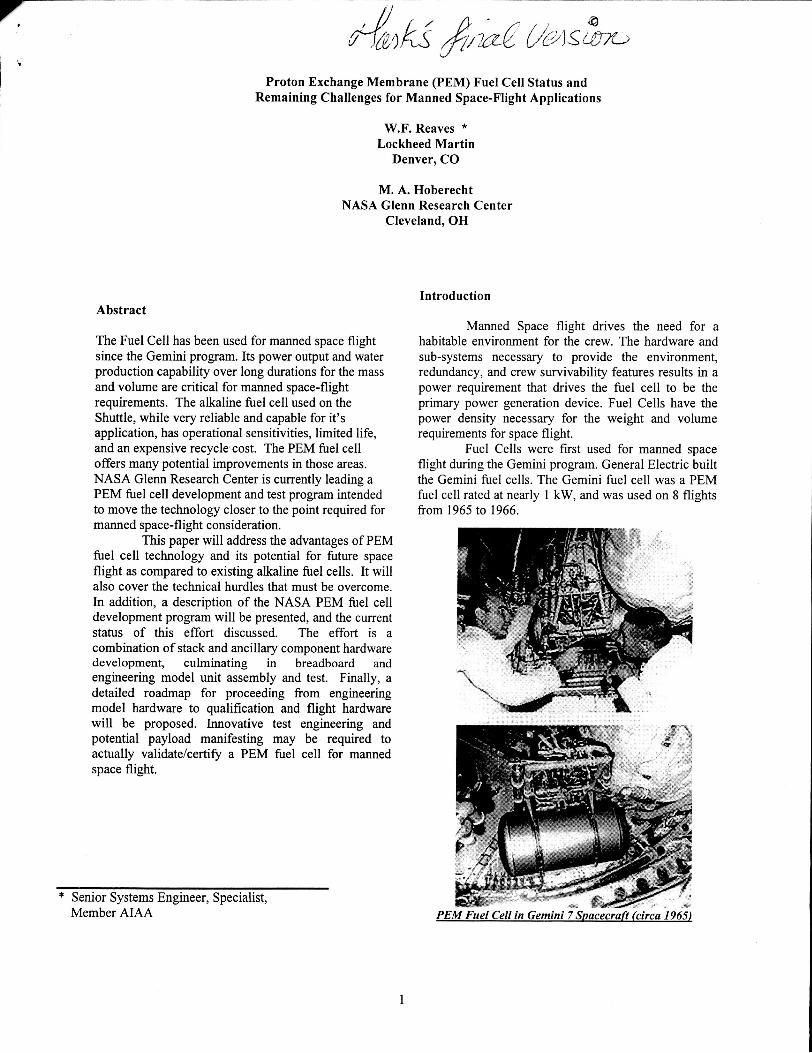
Fuel Cells were first used for manned space flight during the Gemini program. General Electric built the Gemini fuel cells. The Gemini fuel cell was a PEM fuel cell rated at nearly 1 kW, and was used on 8 flights fiom 1965 to 1966.
8 I.
PEM Fuel Cell in Gemini 7 Suacecraft (circa 1965L
1

The Apollo program used alkaline fuel cells during the 18-flight program from 1966 to 1978. United Technologies developed the alkaline fuel cell for the Apollo program. The Apollo fuel cell was rated at 1.5 kW and weighed 250 pounds. During the 18 flights, the fuel cells operated nearly 1 1,000 hours total.
A D O ~ ~ O Fuel Cell (Courtesy UTC Fuel Cells)
Space Shuttle Power Generation Systems Current ConditionsIStatus
Space Shuttle Fuel Cell I PRSD System Description
The Shuttle Fuel Cell is built by UTC Fuel ompany.
Shuttle Fuel Cell Powerplant lcourtesv UTC Fuel Cells)
is reusable and restartable. The fuel cells are located in the orbiter's midfuselage.
The three fuel cells operate as independent electrical power sources, each supplying its own isolated, simultaneously operating 28-volt dc bus. The fuel cell consists of a power section, where the chemical reaction occurs, and an accessory section that controls and monitors the power section's performance. The power section, where hydrogen and oxygen are transformed into electrical power, water and heat, consists of 96 cells contained in three substacks. Manifolds run the length of these substacks and distribute hydrogen, oxygen and coolant to the cells. The cells contain electrolyte consisting of potassium hydroxide and water, an oxygen electrode (cathode) and a hydrogen electrode (anode).
Each fuel cell power plant is 14 inches high, 15 inches wide and 40 inches long and weighs 260 pounds. The accessory section monitors the reactant flow, removes waste heat and water from the chemical reaction, and controls the temperature of the stack. The accessory section consists of the hydrogen and oxygen flow system, the coolant loop and the electrical control unit.
Reactant consumption is directly related to the electrical current produced: if there are no internal or external loads on the fuel cell, no reactants will be used by the fuel cells. Because of this direct proportion, leaks may be detected by comparing reactant consumption and current produced. An appreciable amount of excess reactants used indicates a probable leak. Water, heat and electricity are the products of the chemical reaction of oxygen and hydrogen that takes place in the fuel cells. The water must be removed or
reaction efficiency. With an operating load of about 7 kilowatts, it takes a few minutes to flood the fuel cell with product water, thus effectively halting power
reacts with oxygen, picking up and removing water
The program has 25 during the he cells will become with water, decreasing '13 flight program lggl to 2003* There are presently 18 fuel cells still in service and one additional qualification unit. The Shuttle fuel cell provides 12kW
for 113 shuttle fights. power Output and has provided Over hours generation. As hydrogen is pumped through the stack, it
The Space Shuttle power generation systems utilize three alkaline fuels cells to provide 28 Vdc power to three main and three essential buses. Hydrogen and oxygen reactant gases are supplied to the fuel cells at supercritical pressure from the power reactant and storage distribution (PRSD) system. The following is a discussion of these systems for the reader to gain a little howledge of these systems and also to understand the complexity of the orbiter fuel cell and PRSD systems to better understand the work task time and man-hours involved.
There are three fuel cells in each orbiter providing 28 VDC to three main busses and three essential busses. Each of the three fuel cell power plants
vapor on the way. After being condensed, the liquid water is separated from the hydrogen by the hydrogen pump/water separator and discharged from the fuel cell primary water discharge line to be stored in the Environmental Control and Life Support (ECLSS) potable water storage tanks. An alternate water delivery line is also available to deliver water to the ECLSS tanks if the primary line is blocked. If the water tanks are full or there is line blockage, the water relief valves open at 45 psia to allow an adhtional fuel cell water discharge path overboard. Each fuel cell will be serviced between flights and reused until each accumulates 2,500 hours of on-line service. Historically, the fuel cells have required removal and
2

I .
replacement at approximately 1400 - 1500 hours due to accessory component problems.
The PRSD system is comprised of cryogenic tanks, valve manifolds, and plumbing to supply hydrogen and oxygen reactants to the fuel cells. Cryogenic hydrogen and oxygen are stored in a supercritical condition in double-walled, thermally insulated spherical tanks with a vacuum annulus between the inner pressure vessel and outer shell of the tank.
Each tank has heaters to add energy to the reactants during depletion to control pressure. Each tank is capable of measuring the quantity of remaining stored reactant. The tanks are grouped in sets consisting of one hydrogen and one oxygen tank. The number of tank sets installed depends on the specific mission requirement. Up to five tank sets can be installed. The current baseline is five tank sets and all are installed in the midfuselage under the payload bay liner.
Process Description: Landing Shortly following wheel stop, limited personnel are allowed to approach the vehicle to perform sniff checks to verify the vehicle is safe to work around. Once auxiliary power unit (APU) shutdown is complete, the access vehicles can be positioned at the aft of the vehicle. Following vehicle safing and APU shutdown, the shuttle cooling and purge trucks are positioned at the aft of the vehcle to establish ground cooling and purge air.
Orbiter Post Landing Ouerations fLMC photo)
By providing these ground services, the shuttle fuel cells remain powered up and running, thereby not requiring a vent path for the PRSD cryogenic tank boil- off. If the vehicle is powered down the 1214 & 1215 cry0 venting package is installed at the H2 and 0 2 aft interfaces to control PRSD venting. The alternative is the uncontrolled venting of both tanks thru their respective relief valves and overboard discharge ports, which is not an operationally fliendly method. If the
fuel cells are shutdown and vehcle power is required, the C70-1115 mobile ground power unit may be used. The Fuel Cell / PRSD hazards associated with landing are because of the high pressure cryogenics stored in the Orbiter midbody and the potential of hydrogen and oxygen venting from the aft interfaces (controlled) or the Orbiter PRSD overboard relief valves (uncontrolled).
Orbiter Processing Facility (OPF) Within a single work shft, the vehicle convoys
to the OPF, is jacked and leveled, and work platforms are moved into place. The OPF stays in a hazardous condition, meaning that only essential personnel are allowed access until the fuel cells are shutdown, the PRSD Cry0 detank is completed, and both systems are inerted. Until the Orbiter PRSD hydrogen and oxygen tanks are mated to the OPF facility vent system, the fuel cells remain running. Once the fuel cells are shut down, the PRSD cryogenics are offloaded and inerted. Following fuel cell inert and repressurization, safety H2 sniff checks are performed and the OPF his@ bay is then opened for normal work. The post landing OPF Fuel Cell / PRSD hazardous operations are usually completed within seven 8-hour shifts.
Once the bay is opened, the normal processing of the orbiter’s sub-systems begins. The orbiter midbody and aft compartments are opened, and access platforms and hardware protective cover sets are installed for routine maintenance and subsystem checkouts. This occurs approximately 3-4 days after landing. The Shuttle Fuel Cell / PRSD systems are checked and verified after each mission in the orbiter processing facility.
The Shuttle fuel cell has experienced several problems over the years that were attributed to human error. Although the fault can not be attributed to the fuel cell and is not unique to alkaline fuel cells, it is an indication of the operational sensitivity of the fuel cell. As an example, the H2 FC purge port was inadvertently capped following the fuel cell diagnostic test during an orbiter turnaround work flow. Data analysis ftom the diagnostic test resulted in the decision to remove a fuel cell. During preparation for fuel cell removal, the fuel cell was depressurized, but because a cap was inadvertently installed on the H2 purge port, the hydrogen side of the fuel cell remained pressurized with the oxygen side depressurized, violating a critical requirement that resulted in damage to the fuel cell.
Risk Assessment with New Technologies There are several new power generation
system technologies that will be discussed and analyzed to determine costs and benefit to acheving NASA goals. New technologies should be evaluated against the existing shuttle systems using the following
3

criteria. The first is safety improvements. Technologies should reduce hazards, reduce critical failure modes, and increase reliability. The second is supportability improvements. Technologies should reduce turnaround time, decrease failure rates, reduce obsolescence, reduce costs of repairs, and reduce the loss of vendors. Thxd is operations cost reductions. Technologies should focus on reduction of costs in the following areas: processing activities, facilities, logistics, training, and mission planning and operations. Fourth is mission effectiveness. Technologies should provide for efficient use of crew resources and increase probability of mission objectives, flexibility, and on-time launch.
Next Generation Launch Technologies (NGLT): PEM Fuel Cell
NASA Glenn is presently leading a five-year program to develop PEMFC power plants for NGLT vehicles. The work is being performed under the TA3 NASA SLI program. Presently two contractors are developing hardware under NASA Glenn contracts. Phase 1 of the program will develop breadboard units, which will advance the technology readiness level (TRL) from 4 to 5. Vendor testing is scheduled for completion during the summer of 2003. Phase I1 of the program will down-select to one vendor and that vendor will develop an engineering model unit. The engineering model unit testing, coupled with further component development, should advance the TRL level from 5 to 6. Engineering model testing is scheduled to start in late 2004. The current power plant designs are based on modular 30-V substacks with 4: 1 peak power capability within voltage regulation. These power plants will have at least a 6:l total peak power capability with surge response times of less than 1 millisecond.
Modular PEM fuel cell power plant design consists of multiple stacks with maximum design flexibility for specific application for a wide variety of missions. The PEM fuel cell system can be optimized to minimize power plant weight, reactant consumption, or configured for multiple voltages. One of the primary objectives of the PEM fuel cell technology development is to demonstrate the improved capability over existing Shuttle alkaline FC technology. Lab tests indicate the PEM FC has the potential for 3 times the power and 4 times the life of the alkaline FC for the same weight and volume. The PEM FC has at least a 6:l peak to nominal power rating. The PEM FC also utilizes reduced hazardous materials and has fewer critical failure modes, enabling a significant reduction in ground processing turnaround. For example, since the PEM FC does not use potassium hydroxide as an electrolyte in the cell membrane, there is no need to store the FC in an inert environment or shpping container. Orientation of the PEM FC is not critical when unpressurized, nor is the
PEM FC sensitive to minor pressure imbalances with respect to hydrogen and oxygen pressures, however the PEM FC does require freeze protection.
The PEM fuel cell currently under development uses water as a coolant instead of FC-40, which is used on the shuttle alkaline fuel cells. The use of FC-40 on shuttle fuel cells dnves the need for an expensive infrastructure and GSE because of the requirements of processing FC-40. The PEM fuel cell will eliminate that cost.
By leveraging the evolving and highly competitive PEM FC commercial market in both the automotive and residential arenas, the aerospace application of fuel cells should be able to take advantage of cost reductions as commercial markets expand and mass production increases. Thru modification of commercial designs for the space environment, the possibility exists that multiple vendors may actually provide competition for the aerospace arena.
Shuttle Power Generation System Focus The fuel cell system is a major cost driver
because of LRU spares and repair costs. The shuttle fuel cell is sensitive to operational parameters, physical orientation, and transportation environments because of the corrosive liquid electrolyte not found in the PEM fuel cell. Additional ground support equipment is required to support fuel cell transport, storage, installation, and removals.
The PEM fuel cell, which is based on the use of a thin sheet of polymer chemically bound with acid radicals instead of the corrosive alkaline electrolyte, is not expected to be as sensitive to the ground processing required for transportation, storage, or orientations during installation or removals.
Operational requirements for NGLT or Orbital Space Plane (OSP) Fuel Cell System
The operational requirements discussed here are based on the experiences of processing the orbiter fuel cell system. Any planned work required on the ground should be targeted for elimination. The following are suggested operational requirements:
Eliminate the fuel cell single cell diagnostic test on the ground. This could be possible by providing fuel cell instrumentation so that single cell performance (i.e. voltage) is available during flight and would be recorded in the vehlcle health monitoring system. Design the fuel cell purge system so that all fuel cell purging may be performed in parallel, including fuel cell reactant purges prior to start and fuel cell inert purges post fuel cell shutdown. Streamline the fuel cell start process allowing the fuel cells to be started in parallel. T h s
0
0
0
4
would reduce the 30 - 45 minute start time per fuel cell by a third. This could be significant should fuel cell start be required for an OSP docked at station as a rescue vehicle. Design the new fuel cells to be started on cold gas from the on-board storage tanks. Design NGLT or OSP fuel cells to be less sensitive to flight and ground operations handling. The fuel cells should be less susceptible to damage from cell flooding. The ability to remove water from the cell without removal from the vehicle should be provided. Design the fuel cell to be tolerant of high cross pressure differential changes between the oxygen and hydrogen sides. T h s is inherently true of PEM Fuel Cell technology and will eliminate the need for sophisticated and expensive pressure control ground support equipment. Design the fuel cell to allow for removal and replacement of components in the accessory section without removal of the fuel cell from the vehicle. Specify all fluid line connections to the fuel cell to be flex hoses and quick disconnects where feasible. Provide electrical test points on the fuel cell for ease of troubleshooting component failures.
Remaining Challenges While the PEM fuel cell offers potential
advantages of increased power and life, reduced hazardous material (KOH, Asbestos), and reduced ground turnaround operations, the fact remains that challenges still exist that must be overcome in order to design a man-rated space vehcle utilizing PEM fuel cells. It has been estimated by the leading fuel cell vendors in this country that a PEM fuel cell flight qualification program would take three years and cost between 25 and 30 million. NASA has initiated t h l s activity, but significant investment still needs to occur to bring the PEM fuel cell to a point where it can be certified for flight.
Present PEM fuel cells are gravity dependent on the removal of water from the oxygen gas stream or cathode side of the fuel cell. Actively removing water fi-om a PEM fuel cell may be a problem due to the fact PEM fuel cell integrity and efficiency is dependent on even distribution of H20 across the cell structure. “Product water is removed from the fuel cell at the cathode by passing excess oxygen through the cell, entraining the water” (GRC RFI, 2002, p.1). The resulting fuel cell product water may be in a liquid state, vapor state, or a combination of both. Most of the water needs to be separated from the oxygen gas stream
for two reasons. One, water on a manned space craft is planned as a consumable for both potable water and water for the flash evaporator system. Two, the oxygen must be recirculated back to the fuel cells to minimize wasted reactant gas. The alkaline fuel cell power plant for the Space Shuttle provided by UTC Fuel Cells utilizes an active water separator, which combines water separation with reactant recirculation. Whatever type of water separation device is used, it must be gravity independent and operable under a range of conditions from launch conditions (3-g) to low microgravity (0-g).
The PEM fuel cell also is different from the alkaline fuel cell in regards to reactant consumption. The fundamental electrochemistry of alkaline results in higher voltages than does the PEM. Since voltage equals efficiency in general, the PEM is about 5% or so less efficient than alkaline. PEM is also more susceptible to internal cross-diffusion losses, which further subtract from efficiency. When designing a fuel cell for a man-rated space vehcle, reactant consumption rate is critical to meeting weight, volume, and power levels required. However, PEM fuel cells are capable of operating at much higher current densities than alkaline fuel cells, thereby providing a significant peak power capability. Any mherent efficiency penalty suffered by PEM can be more than offset by this peakmg capability.
There is a great need for developing more robust components for space qualified fuel cells. Fuel cell LRUs need to be designed to allow repair in place. Next generation fuel cells and LRUs need to be designed and built for ease of problem isolation and correction locally.
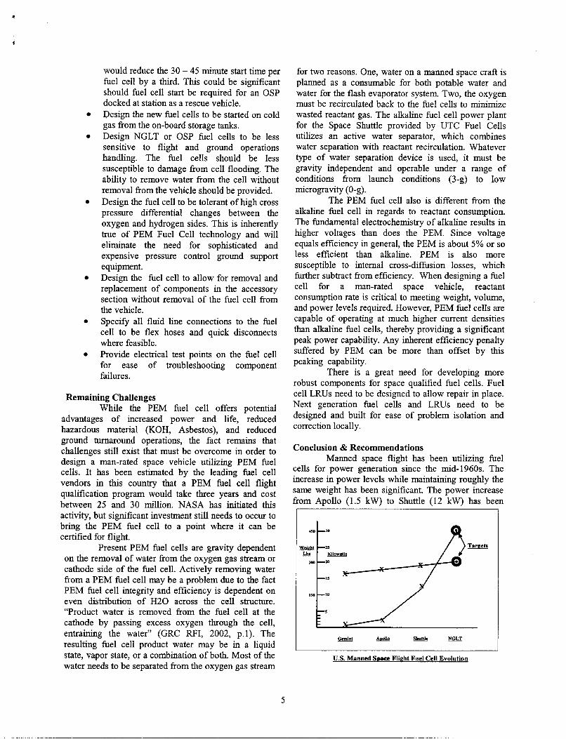
Conclusion & Recommendations Manned space flight has been utilizing fuel
cells for power generation since the mid-1960s. The increase in power levels while maintaining roughly the same weight has been significant. The power increase from Apollo (1.5 kW) to Shuttle (12 kW) has been
US. Manned SIB- Flieht Fuel Cell Evolution
5

about 800%. The next generation of OSP and NGLT space
vehicles will also require power generation for their flight elements. Technologies are presently in the development stage that will allow these vehcles to meet mission, safety, cost, and schedule requirements. PEM fuel cells are one of these technologies.
While the PEM fuel cell offers many potential benefits, there are still remaining challenges to be overcome before they can actually be applied to manned space flight. The water removal from the PEM fuel cell will need an advanced device in lieu of gravity that is the present means. A robust proton exchange membrane will need to be developed that will be able to stand the rigors of launch while still retaining it’s voltage producing efficiency. These advancements need to occur to bring the PEM fuel cell to a point where it can be certified for flight. Significant funding will be required to achieve these advancements and follow through with flight certification.
References:
Daubert, D., Hoberecht, M. (2002). PEM (Proton Exchange Membrane) Fuel Cell, Technical Review #3 2GRLV TA3 Vehicle Subsystems Power I Actuation Technologies, October 2, 2002. In support of 2GRLV I NRA 8-30 - TA-3.
DeRonck H., Zarzyki M., Fuel Cells for Space Applications, 2003. UTC Fuel Cells.
Freudenberger, J., Reaves, W. (2003), Reusable Launch Vehicle (RLV) Power Generation Systems Trail from 1st to 2nd Generation. AIAA 41st Aerospace Sciences meeting and Exhibition Conference Committee.
NASA/USA Systems Engineering and Integration Teani (1996) Orbiter Uumade Studv, p. 11 - 158.
Acronvm List: APU - Auxiliary Power Unit ECLSS - Environmental Control and Life Support FC - Fuel Cell GRC - Glenn Research Facility KOH - Potassium Hydroxide LRU - Line Replaceable Unit PEM - Proton Exchange Membrane PRSD - Power Reactants Storage and Distribution NASA- National Aeronautics and Space Administration NGLT - Next Generation Launch Technology OPF - Orbiter Processing Facility OSP - Orbital Space Plane TRL - Technical Readiness level UTC - United Technologies Company
Space Shuttle Reference Manual (1988) from: httu:l/www.spaceflight.nasa. govlshuttlelrefere ncelshutreflindex.htm1
6