and is issued for the information of such persons only as ... Modification Instructions ... Single...
278
ARMY EQUIPMENT UK RESTRICTED 5895-H-514-304 SUPPORT PUBLICATION MAY 1987 The information within this publication is released by the UK Government to the recipient in accordance with the conditions of Release at Page(ii) SECONDARY ACCESS SWITCH/MESSAGE CENTRE (TRACKED) IN AFV 439 TECHNICAL DESCRIPTION This publication contains information covering the requirements of categories 3,4.1,5.1,5.2,5.3 and 7.1 at level 4. 'THIS DOCUMENT IS THE PROPERTY OF HER BRITANNIC MAJESTY'S GOVERNMENT, and is issued for the information of such persons only as need to know its contents in the course of their official duties. Any person finding this document should hand it to a British forces unit or police station for its safe return to the MINISTRY OF DEFENCE, O MOD SY, LONDON SW1A 2HB with particulars of how and where found. THE UNAUTHORIZED RETENTION OR DESTRUCTION OF THE DOCUMENT IS AN OFFENCE UNDER THE OFFICIAL SECRETS ACT OF 1911-39. (When released to persons outside Government service this document is issued on a personal basis and the recipient to whom it is entrusted in confidence, within the provisions of the Official Secrets Act 1911-39, is personally responsible for its safe custody and for seeing that its contents are disclosed only to authorized persons).' BY COMMAND OF THE DEFENCE COUNCIL Ministry of Defence Sponsor: DGEME (Disc ref: HHL.039) Publication Authority: Electronics Branch REME -1 Comments on the contents of this publication should be submitted in accordance with AESP O100-P-O11-013 REPRINTED INCORPORATING AMDTS 1-2 UK RESTRICTED Page (i)
Transcript of and is issued for the information of such persons only as ... Modification Instructions ... Single...
ARMY EQUIPMENT UK RESTRICTED 5895-H-514-304SUPPORT PUBLICATION MAY 1987
The information within thispublication is released by the UK
Government to the recipient inaccordance with the conditions of
Release at Page(ii)
SECONDARY ACCESS SWITCH/MESSAGE CENTRE (TRACKED)
IN AFV 439
TECHNICAL DESCRIPTION
This publication contains informationcovering the requirements of categories3,4.1,5.1,5.2,5.3 and 7.1 at level 4.
'THIS DOCUMENT IS THE PROPERTY OF HER BRITANNIC MAJESTY'S GOVERNMENT,and is issued for the information of such persons only as need toknow its contents in the course of their official duties. Any personfinding this document should hand it to a British forces unit orpolice station for its safe return to the MINISTRY OF DEFENCE,O MOD SY, LONDON SW1A 2HB with particulars of how and where found.THE UNAUTHORIZED RETENTION OR DESTRUCTION OF THE DOCUMENT IS ANOFFENCE UNDER THE OFFICIAL SECRETS ACT OF 1911-39. (When released topersons outside Government service this document is issued on apersonal basis and the recipient to whom it is entrusted in confidence,within the provisions of the Official Secrets Act 1911-39, is personallyresponsible for its safe custody and for seeing that its contents aredisclosed only to authorized persons).'
BY COMMAND OF THE DEFENCE COUNCIL
Ministry of Defence
Sponsor: DGEME
(Disc ref: HHL.039)Publication Authority: Electronics Branch REME
-1
Comments on the contents of this publication should besubmitted in accordance with AESP O100-P-O11-013
REPRINTED INCORPORATING AMDTS 1-2
UK RESTRICTED Page (i)
5895-H-514-304 UK RESTRICTED ARMY EQUIPMENTSUPPORT PUBLICATION
CONDITIONS OF RELEASE
1. This information is released by the UK Government fordefence purposes only.
2. This information must be accorded the same degree ofsecurity protection as that accorded thereto by the UKGovernment.
3. This information may be disclosed only within the DefenceDepartments of the recipient government, except as otherwiseauthorized by the Ministry of Defence (Army).
4. This information may be subject to privately owned rights.
.
S
SPage (ii) UK RESTRICTED May 87
ARMY EQUIPMENTSUPPORT PUBLICATION
UK RESTRICTED 5895-H-514-304
AMENDMENT RECORD
Amdt Incorporated by Date
1
:
4
5
6
7
8
9
10
11
12
13
14
15
16
17
18
19
20
21
22
23
24
25
Amdt Incorporated by Date
26
27
28
29
30
31
32
33
34
35
36
37
38
39
40
41
42
43
44
45
46
47
48
49
50
May 87 UK RESTRICTED Page (iii)/(iv)

L
.
.
.

ARMY EQUIPMENTSUPPORT PUBLICATION
Chapters
UK RESTRICTED
CONTENTS
5895-H-514-304
1 Preparation of Vehicle2 Local Manufactured Items3 Vehicle Conversion4 Vehicle Cladding Installation5 External Installation6 Internal Installation7 Installation checkout and test procedures
Preliminary Material Page
Title page (front cover) (i)/(ii)Amendment Record Sheet (iii)/(iv)Contents (this list) (v)PREFACE (vi)Introduction (vi)Related Publications (vi)Associated Publications (vii)List of Abbreviations (vii)Warnings (viii)Emergency Resuscitation Form 656
May 87 UK RESTRICTED Page (v)
5895-H-514-304 UK RESTRICTED
PREFACE
ARMY EQUIPMENTSUPPORT PUBLICATION
Publications AuthorityElectronics Branch REMELeigh Sinton Road, Malvern,Worcestershire, WRJ4 iLL
Codified Title: Carrier Installation, Secondary Access Switch/Message Centre(Tracked) AFV 439
INTRODUCTION
1 Service users should forward any comments on this publication through thechannel prescribed in AESP 0100-P-011-013 (JSP 182 Chap 4-1 Para 9 refers).
2 The subject matter of this publication may be affected by Defence CouncilInstructions (DCIs), Standing Operating Procedures (SOPs) or by LocalRegulations (IRs). When any such Instruction, Order or Regulation contradictsany portion of this publication it is to be taken as the overridingauthor I ty.
RELATED PUBLICATIONS
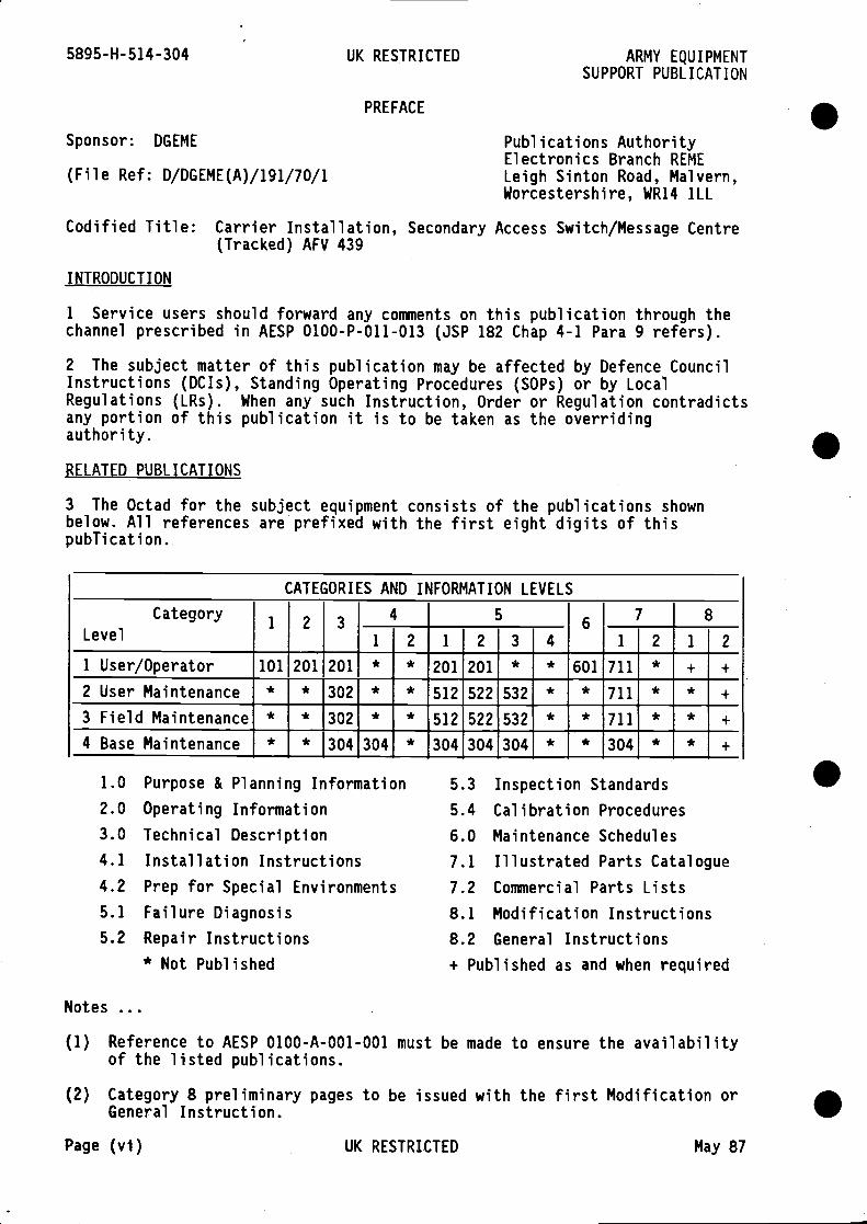
3 The Octad for the subject equipment consists of the publications shownbelow. All references are prefixed with the first eight digits of thispublication.
Notes
Purpose & Planning InformationOperating InformationTechnical DescriptionInstallation InstructionsPrep for Special EnvironmentsFailure DiagnosisRepair Instructions* Not Published
5.3 Inspection Standards5.4 Calibration Procedures6.0 Maintenance Schedules
7.1 Illustrated Parts Catalogue7.2 Commercial Parts Lists8.1 Modification Instructions8.2 General Instructions+ Published as and when required
(1) Reference to AESP 0100-A-O01-001 must be made to ensure the availabilityof the listed publications.
(2) Category 8 preliminary pages to be issued with the first Modification orGeneral Instruction.
Page (vi) UK RESTRICTED May 87
.
Sponsor: DGEME
(File Ref: D/DGEME(A)/191/70/i
CATEGORIES AND INFORMATION LEVELS
CategoryLevel
1 2 3 67 8
1 2 1 21 2 1 2 3 4
1 User/Operator 101 201 201 * * 201 201 * * 601 711 * + +
2 User Maintenance * * 302 * * 512 522 532 * * 711 * *
3 Field Maintenance * * 302 512 522 532 * * 711 * *
4 Base Maintenance * * 304 304 * 304 304 304 * * 304 * *
.
.1.0
2.0
3.04.1
4.2
5.1
5.2
ARMY EQUIPMENT UK RESTRICILD 5895-H-514-304SUPPORT PUBLICATION
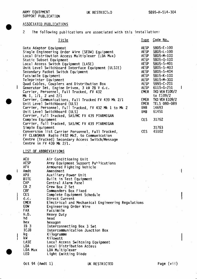
ASSOCIATED PUBLICATIONS
2 The following publications are associated with this installation:
Title Type Code No.
Data Adaptor Equipment AESP 5805E100Single Engineering Order Wire (SEOW) Equipment AESP 5805-L-100Local Distribution Access Multiplexer (LDA Mux) AESP 5805-M-100Static Subset Equipment AESP 5805-Q-100Local Access Switch Equipment (LASE) AESP 5805-S—401Unit Level Switchboard Interface Equipment (ULSIE) AESP 5805-S-403Secondary Packet Switch Equipment AESP 5805-S-404Facsimile Equipment AESP 5815-K-100Teleprinter Equipment AESP 5815-M-300Quad Cables, Couplers and Distribution Box AESP 5995-C-201Generator Set, Engine Driven, 3 kW 28 V d.c. AESP 6115-G-251Carrier, Personnel, Full Tracked, FV 432 EMER TKDVEHE100/2Mk 1, 1/1, 2 and 2/1 to E109/2. Carrier, Communications, Full Tracked FV 439 Mk 2/1 EMER TKDVEHE1O9/2Unit Level Switchboard (ULS) EMER TELS 080-089Carrier, Personnel, Full Tracked, FV 432 Mk 1 to Mk 2 UHB 14693Unit Level Switchboard (ULS) UHB 61451Carrier, Full Tracked, SAS/MC FV 439 PTARMIGANComplex Equipment CES 31762Carrier, Full Tracked, SAS/MC FV 439 PTARMIGANSimple Equipment 31763Conversion list Carrier Personnel, Full Tracked, CES 45102FF CLANSMAN Radio F432 Mk2, to CommunicationCentre (Tracked) Secondary Access Switch/MessageCentre in FV 439 Mk 2/1.
LIST OF ABBREVIATIONS
ACU Air Conditioning UnitAESP Army Equipment Support PublicationsAFV Armoured Fighting VehicleAmdt AmendmentAPU Auxiliary Power UnitBITE Built in Test EquipmentCAP Central Alarm PanelCB 2 Crew Box 2 SetCBF Commanders Box FixedCES Complete Equipment Scheduled.c. Direct CurrentEMER Electrical and Mechanical Engineering RegulationsEOW Engineering Order WireFAX FacsimileH.D. Heavy Dutyhd headhex hexagonlB 3 Interconnecting Box 3 SetICJB Intercommunication Junction Boxkg KilogrammekW KilowattLASE Local Access Switcning EquipmentLDA Local Distribution AccessLDA Mux LDA MultiplexerLED Light Emitting Diode
Oct 94 (Amdt 1) UK RESTRICTED Page (vii)
5895-H-514-304 UK RESTRICTED ARMY EQUIPMENTSUPPORT PUBLICATION
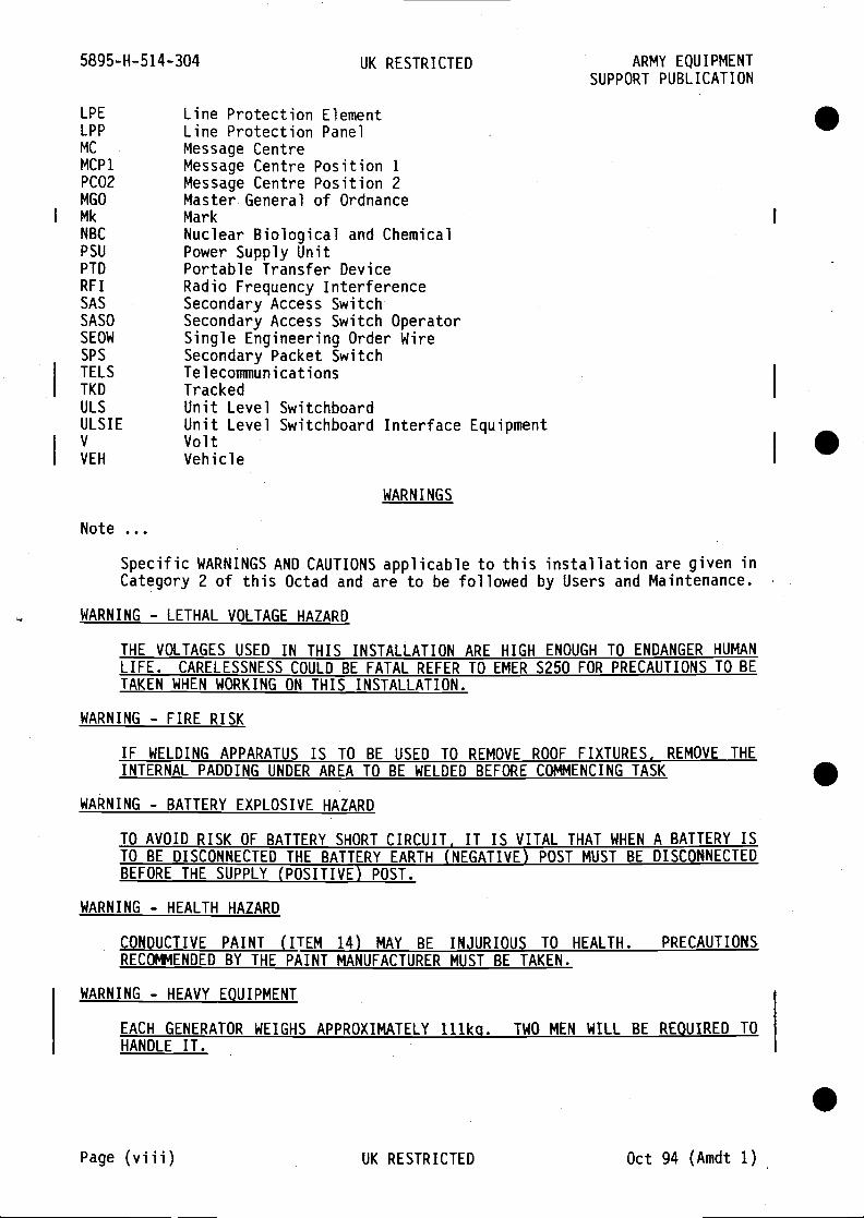
LPE Line Protection ElementLPP Line Protection PanelMC Message CentreMCPI Message Centre Position 1PCO2 Message Centre Position 2MGO Master General of OrdnanceMk MarkNBC Nuclear Biological and ChemicalPSU Power Supply UnitPTD Portable Transfer DeviceRFI Radio Frequency InterferenceSAS Secondary Access SwitchSASO Secondary Access Switch OperatorSEOW Single Engineering Order WireSPS Secondary Packet SwitchTELS TelecommunicationsTKD TrackedULS Unit Level SwitchboardULSIE Unit Level Switchboard Interface EquipmentV VoltVEH Vehicle
WARNINGS
Note
Specific WARNINGS AND CAUTIONS applicable to this installation are given inCategory 2 of this Octad and are to be followed by Users and Maintenance.
WARNING - LETHAL VOLTAGE HAZARD
THE VOLTAGES USED IN THIS INSTALLATION ARE HIGH ENOUGH TO ENDANGER HUMANLIFE. CARELESSNESS COULD BE FATAL REFER TO EMER S250 FOR PRECAUTIONS TO BETAKEN WHEN WORKING ON THIS INSTALLATION.
WARNING - FIRE RISK
IF WELDING APPARATUS IS TO BE USED TO REMOVE ROOF FIXTURES. REMOVE THEINTERNAL PADDING UNDER AREA TO BE WELDED BEFORE COMMENCING TASK
WARNING - BATTERY EXPLOSIVE HAZARD
TO AVOID RISK OF BATTERY SHORT CIRCUIT. IT IS VITAL THAT WHEN A BATTERY ISTO BE DISCONNECTED THE BATTERY EARTH (NEGATIVE) POST MUST BE DISCONNECTEDBEFORE THE SUPPLY (POSITIVE) POST.
WARNING - HEALTH HAZARD
CONDUCTIVE PAINT (ITEM 14) MAY BE INJURIOUS TO HEALTH. PRECAUTIONSRECOMMENDED BY THE PAINT MANUFACTURER MUST BE TAKEN.
WARNING - HEAVY EOUIPMENT
EACH GENERATOR WEIGHS APPROXIMATELY 111kg. TWO MEN WILL BE REQUIRED TOHANDLE IT.
.Page (viii) UK RESTRICTED Oct 94 (Amdt 1)
RESUSCITATION
TREATMENT OF THE NON-BREATHING CASUALTY
NOTICE
The inclusion of the emergency resuscitation placard (MOD Form 656) in Military TechnicalPublications has been discontinued.
This notice is to be retained in the publication until removed by amendment instruction.
Oct 91 LSTPA Ref ADMIN/1/17

S
S
S
S
ARMY EQUIPMENTSUPPORT PUBLICATION
UK RESTRICTED 5895-H-514-304
Para
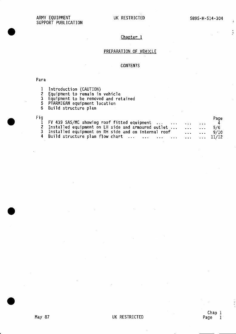
Chanter 1
PREPARATION OF VEHICLE
CONTENTS
1 Introduction (CAUTION)2 Equipment to remain in vehicle3 Equipment to be removed and retained5 PTARMIGAN equipment location6 Build structure plan
Fig1
2
3
4
FV 439 SAS/MC showing roof fitted equipmentInstalled equipment on LH side and armoured outletInstalled equipment on RH side and on internal roofBuild structure plan flow chart
May 87 UK RESTRICTED
Page4
5/69/10
11/12
Chap 1Page 1
5895-H-514-304 UK RESTRICTED ARMY EQUIPMENTSUPPORT PUBLICATION
INTRODUCTION
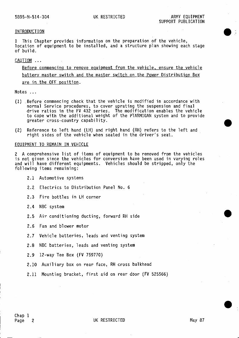
1 This Chapter provides information on the preparation of the vehicle,location of equipment to be installed, and a structure plan showing each stageof build.
CAUTION
Before commencing to remove eguipment from the vehicle, ensure the vehiclebattery master switch and the master switch on the Power Distribution Boxare in the OFF position.
Notes
(1) Before commencing check that the vehicle is modified in accordance withnormal Service procedures, to cover uprating the suspension and finaldrive ratios in the FV 432 series. The modification enables the vehicleto cope with the additional weight of the PTARMIGAN system and to providegreater cross-country capability.
(2) Reference to left hand (LH) and right hand (RH) refers to the left andright sides of the vehicle when seated in the driver's seat.
EQUIPMENT TO REMAIN IN VEHICLE
2 A comprehensive list of items of equipment to be removed from the vehiclesis not given since the vehicles for conversion have been used in varying rolesand will have different equipments. Vehicles should be stripped, only thefollowing items remaining:
2.1 Automotive systems
2.2 Electrics to Distribution Panel No. 6
2.3 Fire bottles in LH corner
2.4 NBC system
2.5 Air conditioning ducting, forward RH side S2.6 Fan and blower motor
2.7 Vehicle batteries, leads and venting system
2.8 NBC batteries, leads and venting system
2.9 12-way Tee Box (FV 759770)
2.10 Auxiliary box on rear face, RH cross bulkhead
2.11 Mounting bracket, first aid on rear door (FV 525566)
..Chap 1Page 2 UK RESTRICTED May 87

ARMY EQUIPMENT UK RESTRICTED 5895-H-514-304SUPPORT PUBLICATION
EQUIPMENT TO BE REMOVED AND RETAINED
3 The following items are to be removed and retained for refitting at a laterstage:
FV 167663/1 Battery lead (services connection) Qty 1FV 167665/2 Battery lead (negative) Qty 1FV 167668/4 Battery lead (positive) Qty 1
4 The following CLANSMAN boxes:
5895-99-117-4911 Crew box 2 set in crew compartment, Qty 1leave crew box in driver's compartment
5820-99-117-6110 Interconnecting box 3 set Qty I
5895-99-117-4909 Commanders Box Fixed Qty 1interconnecting cable assemblies
5820-99-117-5043 Commanders Personal Unit (stowed item) Qty 1
5965-99-620-5667 Cable Assembly Switch Electrical Qty 1(stowed item)
PTARMIGAN EOUIPMENT LOCATION
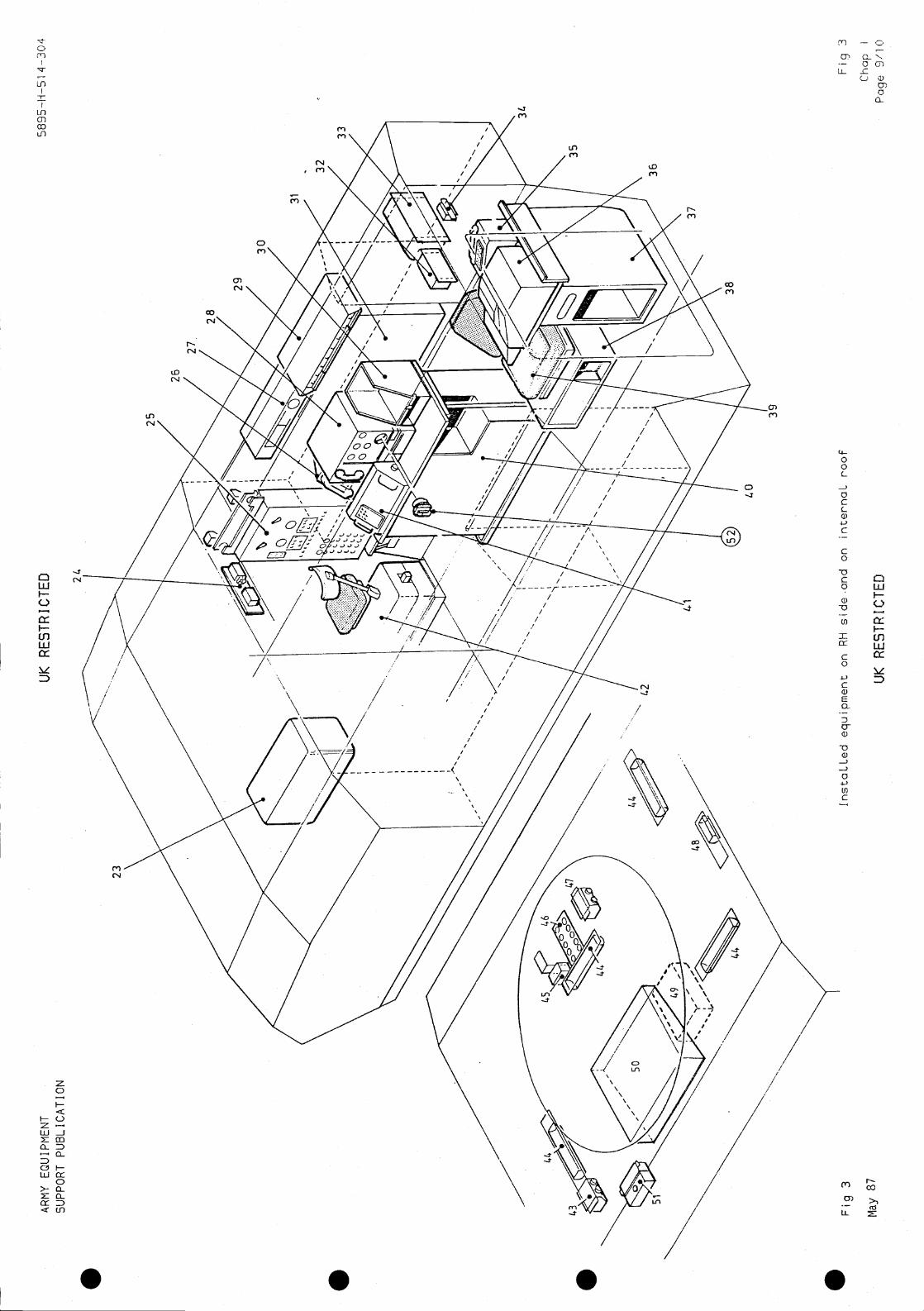
5 The location of PTARMIGAN equipment in the FV 439 Secondary AccessSwitch/Message Centre (SAS/MC) vehicle is shown in Figs 1,2 and 3.
Chap 1
May 87 UK RESTRICTED Page 3

5895-H- 514-304 UK RESTRICTED ARMY EQUIPMENTSUPPORT PUBLICATION
.
.
.
Chap 1Page 4
Fig 1 FV 439 showing roof mounted equipment
UK RESTRICTED Oct 94 (Amdt 1)
.
0
CHASSIS EARTH

KE
Y T
O F
IG 2
1P
atch
pan
el a
ssem
bly
2LD
A M
ultip
lexe
r U
nit (
LDA
MU
X)
3T
elep
rinte
rB
4C
able
ala
rm b
ox a
ssem
bly
5T
ee b
ox B
,C
',D
and
E
6LA
SE
uni
t7
Uni
t filt
er p
rote
ctio
n8
Tab
le to
p an
d st
owag
e9
ULS
exc
hang
e un
it10
Cen
tral
ala
rm p
anel
11V
ehic
le b
atte
ries
12C
omm
unic
atio
n ba
tterie
s13
Arm
oure
d ou
tlet
14U
LSIE
15S
eat S
AS
ope
rato
r16
Sea
t mou
ntin
g fr
ame,
and
sto
wag
e17
Sto
wag
e te
lepr
inte
rB
18F
AX
PS
U a
nd m
ount
ing
tray
ass
embl
y19
Tel
eprin
ter
data
ada
ptor
sub
—se
t20
FA
X u
nit
21D
ata
adap
tor
B
22A
CU
con
trol
(pr
ovis
iona
l)
AR
MY
EQ
UIP
ME
NT
SU
PP
OR
T P
UB
LIC
AT
ION
UK
RE
ST
RIC
TE
D
Fig
2In
staL
Led
equi
pmen
t on
LH s
ide
and
arm
oure
d ou
tLet
May
87
UK
RE
ST
RIC
TE
D
Fig
2C
hap
1
Pag
o 5/
6

. . . .
5895-H-514-304 UK RESTRICTED ARMY EQUIPMENTSUPPORT PUBLICATION
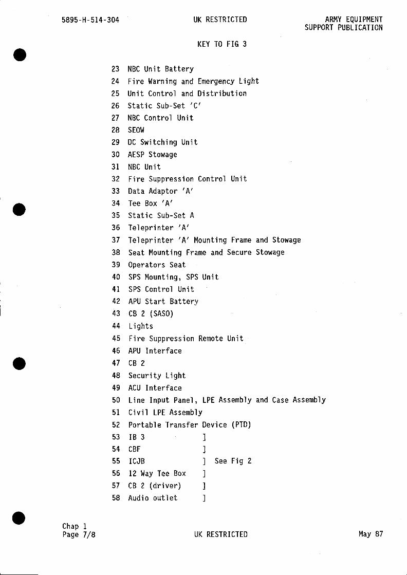
KEY TO FIG 3
23 NBC Unit Battery
24 Fire Warning and Emergency Light
25 Unit Control and Distribution26 Static Sub-Set 'C'27 NBC Control Unit28 SEOW
29 DC Switching Unit30 AESP Stowage
31 NBC Unit
32 Fire Suppression Control Unit33 Data Adaptor 'A'34 Tee Box 'A'35 Static Sub-Set A36 Teleprinter 'A'37 Teleprinter 'A' Mounting Frame and Stowage
38 Seat Mounting Frame and Secure Stowage
39 Operators Seat
40 SPS Mounting, SPS Unit
41 SPS Control Unit42 APU Start Battery43 CB 2 (SASO)
44 Lights45 Fire Suppression Remote Unit46 APU Interface47 CB 2
48 Security Light49 ACU Interface
50 Line Input Panel, LPE Assembly and Case Assembly
51 Civil LPE Assembly
52 Portable Transfer Device (PTD)53 1B3 ]
54 CBF ]
55 ICJB ] See Fig 2
56 12 Way Tee Box I
57 CB 2 (driver)58 Audio outlet I
Chap 1Page 7/8 UK RESTRICTED May 87

S
S
S
S
enen
(N,en
en
CT) — 0
-— CmLL ro C)
C)C
U-
0en
toC.,
(N
N
en
N
in(N'
en
0C?
Lfl
-rU)
0LU
CuJF-0itI-inLUcc
0I-Ch-Cz-.LUJrcn
cL.D
Of—0
>-o-.
CU)
C
4
(-I-00L
aCC-a)
C
C0
C0a)-o
in
U-
C0
Ca)E
aC-C)
-oI)
-JC
U)C
ciLUI—C,
ccF-f-nLUcc
II
/K
en(-4
<K
S S . .cc
a) >)

. . . .
ARMY EQUIPMENTSUPPORT PUBLICATION
UK RESTRICTED 5895-H-514-304
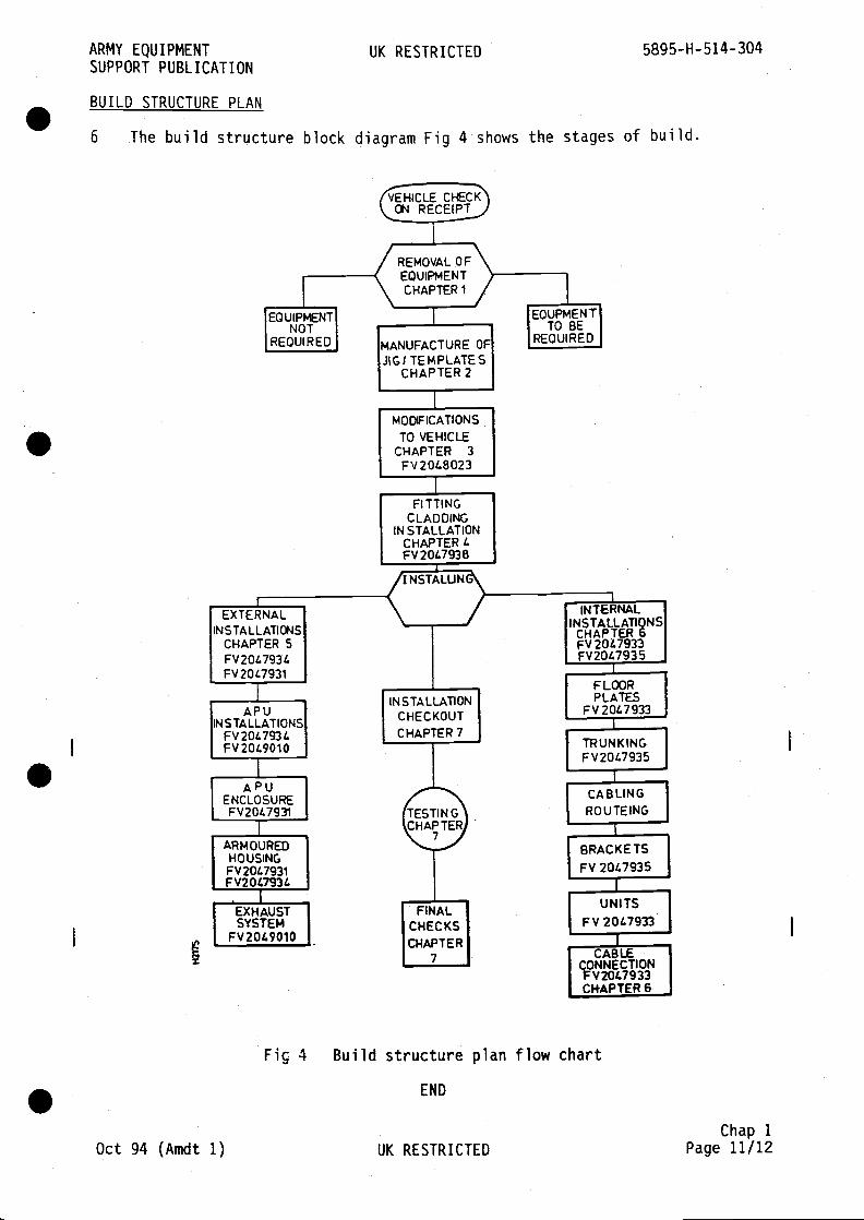
BUILD STRUCTURE PLAN
Fiç 4 Build structure plan flow chart
END
Oct 94 (Amdt 1) UK RESTRICTEDChap 1
Page 11/12
6 The build structure block diagram Fig 4 shows the stages of build.

S
S
S
S

ARMY EQUIPMENT UK RESTRICTED 5895-H-514-304SUPPORT PUBLICATION
ChaDter 2
LOCAL MANUFACTURED ITEMS
CONTENTS
Par a1 Introduction
Fig Page1 Template for floor modification RH side 3/42 Template for floor modification LH side 5/6
Chap 2May 87 UK RESTRICTED Page 1
5895-H-514-304 UK RESTRICTED ARMY EQUIPMENTSUPPORT PUBLICATION
INTRODUCTION
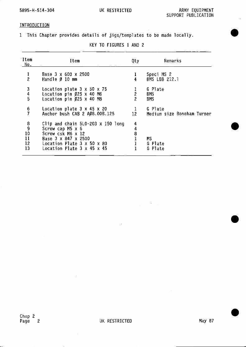
1 This Chapter provides details of jigs/templates to be made locally.
KEY TO FIGURES 1 AND 2
Chap 2Page 2 UK RESTRICTED May 87
.
.
ItemNo.
Item Qty Remarks
1 Base 3 x 600 x 2500 1 Speci MS 22 Handle 0 10 mm 4 BMS LBB 212.1
3 Location plate 3 x 50 x 75 1 G Plate4 Location pin 025 x 40 M6 2 BMS
5 Location pin 025 x 40 MB 2 BMS
6 Location plate 3 x 45 x 20 1 G Plate7 Anchor bush CAB 2 A08.OOB.125 12 Medium size Boneham Turner
8 Clip and chain 5L0-203 x 150 long 49 ScrewcapM5x6 4
10 Screw csk M6 x 12 811 Base 3 x 847 x 2500 1 MS
12 Location Plate 3 x 50 x 80 1 G Plate13 Location Plate 3 x 45 x 45 1 G Plate
.
.

AR
MY
EQ
UIP
ME
NT
UK
RE
ST
RIC
TE
D58
95—
H—
51 4
-304
SU
PP
OR
T P
UB
LIC
AT
ION
0
DR
ILL
2H
OLE
S F
OR
(16
SC
RE
WS
(IT
EM
10)
FR
OM
UN
DE
RS
IDE
OF
ITE
M 1
FO
R H
AN
DLE
(IT
EM
2)A
ND
CO
UN
TE
RS
INK
BO
TH
HO
LES
.
6.55
/6.5
0 W
IDE
SLO
TM
IC O
NA
SS
Y IT
EM
S1&
3 S
PO
T T
HR
U.R
I VE
TH
OLE
S F
RO
M IT
EM
3,
RIV
ET
S F
INIS
H F
LUS
H
SC
ALE
1—
1 &
5—
1U
NS
PE
CIF
IED
TO
LER
AN
CE
S
XH
OLE
X,X
0,5
+0,
1X
,XX
± 0
,1—
0,05
X,X
XX
± 0
,1
2 O
FF
ITE
M 2
1 0F
F IT
EM
S
8.50
/6.4
5 B
TH
RO
MB
N
12 D
P
2 H
OLE
S D
RIL
LA
ND
CS
K F
OR
0 3.
0 C
SK
RIV
ET
1 0F
F IT
EM
6
10F
F G
'PLA
TE
13)
3 H
OLE
S D
RLC
SK
FO
R 0
3.0
CS
K R
IVE
T
II
M/C
HO
LE Ô
NA
SS
Y W
ITH
ITE
M I
Fig
1fe
mpL
ate
For
FLo
or m
odifi
catio
n R
H s
ide
May
87
UK
RE
ST
RiC
TE
D
SP
OT
TH
RU
RIV
ET
HO
LES
FR
OM
ITE
M 6
.R
IVE
TS
FIN
ISH
FLU
SH
US
E
(.1/
C S
LOT
ON
AS
SY
.W
ITH
ITE
M1
44
1 0F
F IT
EM
6A
0 5
.50/
6.45
B T
HR
O M
G
Fig
1
Cha
p 2
Pag
e 3/
4

. . . .

AR
MY
EQ
UIP
ME
NT
SU
PP
OR
T P
UB
LIC
AT
ION
UK
RE
5TR
ICT
ED
5895—H—51 4—304
SC
ALE
1-1
&U
NS
PE
CIF
IED
x±
1,0
X,X
±0,
5X
,XX
±0,
1
5-1
TO
LE
RA
N C
ES
HO
LE 0
4 0,
1
- 0,
05
It, 0 S
LII
5 H
OLE
S 0
250
DR
ILL
2 H
OLE
S &
CO
UN
TE
RS
INK
FR
OM
UD
ER
SID
E O
F IT
EM
1F
OR
HA
ND
LE (
ITE
M 2
)
Fig
2TempLate for fLoor modification LH side
END
May 87
UK
RE
ST
RIC
TE
D
6.55
16•5
0 W
IDE
SLO
TM
/C O
N A
SS
Y IT
EM
S1
& 3
SP
OT
TH
RU
.R
IVE
T H
OLE
S F
RO
MIT
EM
3. R
IVE
TS
FIN
ISH
FLU
SH
.
2 H
OLE
S T
AP
DR
ILL
1 H
OLE
TH
RU
.
SP
OT
TH
RU
. FR
OM
ITE
M 6
RIV
ET
S F
INIS
H F
LUS
HX
,XX
X ±
0,1
10F
F IT
EM
1.
A 0
6.50
/6.4
5 B
TH
RU
.M.6
1 0F
F IT
EM
510
FF
ITE
M 1
2
7
4 H
OLE
S D
RIL
LA
ND
3'O
C'S
I< R
IVE
T.
2OF
FB
MS
ITE
M 2
M/C
HO
LEO
NA
SS
EM
BLY
WIT
HIT
EM
1
10F
F IT
EM
612
5.1
Fig 2
Cha
p 2
Pag
e 5/
8

. . . .

ARMY EQUIPMENTSUPPORT PUBLICATION
UK RESTRICTED 5895-H-514-304
IntroductionTools and equipmentMaterialsWeldingGeneralSequenceItem numbering
- external5 Modifications6 Modifications7 Modifications8 Modifications9 Modifications
10 Modificationscomplete RH
11 Modifications12 Modifications13 Modifications14 Modifications15 Modifications16 Modifications
totototototo
Page45
81011
1213141516171820212324
33/3435/3637/3839/4041/4243/44
45/4647/4849/5051/5253/5455/56
May 87 UK RESTRICTEDChap 3
Page 1
Chaoter 3
VEHICLE CONVERSION
CONTENTS
Para1
4
6
7
910:ii
VEHICLE CONVERSION INSTRUCTIONSNo.
1 Roof salvage ...2 Armoured housing, APU mounting,
Turret ccver p1 ate3 Pads and blanking plates ... ...4 LH side plate upper - external ...5 Roof plate, UI side - internal ... ...6 LH side plates, internal ... ...7 Cross bulkhead ... ... ...8 RH side plate - internal ... ...9 Cover plate - fuel tank RH assembly
10 Fuel tank end protection plate, complete, RH11 Rear bulkhead - internal ... ...12 Roof, internal13 Pannier plate LH ... ... ...14 Floor - internal ... ... ...15 Audio Adaptor Assembly ... ...16 NBC unit casing ... ... ...
Fig1 Roof salvage FV 2048020 ...2 Pads and blanking plates FV 20479853 Modifications to roof external FV 20479844 Modifications to LH side plate - upper FV 2048040
Page25/2627/2829/303 1/32
roof plate, side LH - internal FV 2048509LH side plates - internal FV 2048016cross bulkhead FV 2048018 ...RH side plates - internal FV 2048017cover plate, fuel tank RH complete FV 2048508fuel tank end protection plate FV 2048663
to rear bulkhead - internal FV 2048019to roof - internal FV 2048015 ...to pannier plate LH FV 2048507 ...to floor - internal FV 2048024 ...to roof - audio adaptor assembly FV 651490to NBC casing FV 2048633 ... ...
5895-H-514-304 UK RESTRICTED ARMY EQUIPMENTSUPPORT PUBLICATION
INTRODUCTION
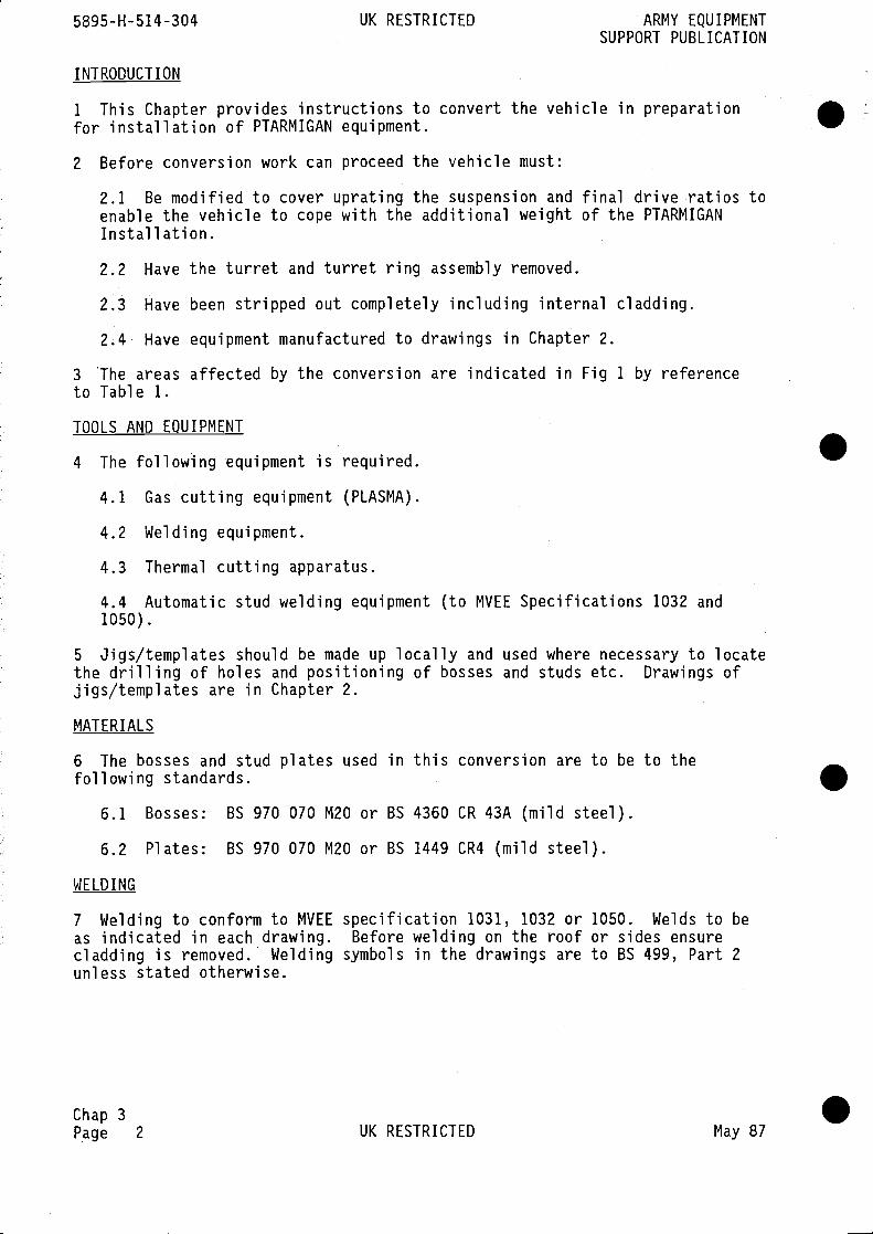
1 This Chapter provides instructions to convert the vehicle in preparationfor installation of PTARMIGAN equipment.
2 Before conversion work can proceed the vehicle must:
2.1 Be modified to cover uprating the suspension and final drive ratios toenable the vehicle to cope with the additional weight of the PTARMIGANInstallation.
2.2 Have the turret and turret ring assembly removed.
2.3 Have been stripped out completely including internal cladding.
2.4 Have equipment manufactured to drawings in Chapter 2.
3 •The areas affected by the conversion are indicated in Fig 1 by referenceto Table 1.
TOOLS AND EQUIPMENT
4 The following equipment is required.
4.1 Gas cutting equipment (PLASMA).
4.2 Welding equipment.
4.3 Thermal cutting apparatus.
4.4 Automatic stud welding equipment (to MVEE Specifications 1032 and1050).
5 Jigs/templates should be made up locally and used where necessary to locatethe drilling of holes and positioning of bosses and studs etc. Drawings ofjigs/templates are in Chapter 2.
MATERIALS
6 The bosses and stud plates used in this conversion are to be to thefollowing standards.
6.1 Bosses: BS 970 070 M20 or BS 4360 CR 43A (mild steel).
6.2 Plates: BS 970 070 M20 or BS 1449 CR4 (mild steel).
WELDING
7 Welding to conform to MVEE specification 1031, 1032 or 1050. Welds to beas indicated in each drawing. Before welding on the roof or sides ensurecladding is removed. Welding symbols in the drawings are to BS 499, Part 2unless stated otherwise.
Chap 3Page 2 UK RESTRICTED May 87
ARMY EQUIPMENT UK RESTRICTED 5895-H-514-304SUPPORT PUBLICATION
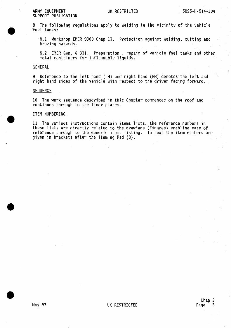
8 The following regulations apply to welding in the vicinity of the vehiclefuel tanks:
8.1 Workshop EMER 0360 Chap 13. Protection against welding, cutting andbrazing hazards.
8.2 EMER Gen. 0 331. Preparation , repair of vehicle fuel tanks and othermetal containers for inflammable liquids.
GENERAL
9 Reference to the left hand (LH) and right hand (RH) denotes the left andright hand sides of the vehicle with respect to the driver facing forward.
SEQUENCE
10 The work sequence described in this Chapter commences on the roof andcontinues through to the floor plates.
ITEM NUMBERING
11 The various instructions contain items lists, the reference numbers inthese lists are directly related to the drawings (Figures) enabling ease ofreference through to the Generic items listing. In text the item numbers aregiven in brackets after the item eg Pad (8).
Chap 3May 87 UK RESTRICTED Page 3
5895-H-514-304 UK RESTRICTED ARMY EQUIPMENTSUPPORT PUBLICATION
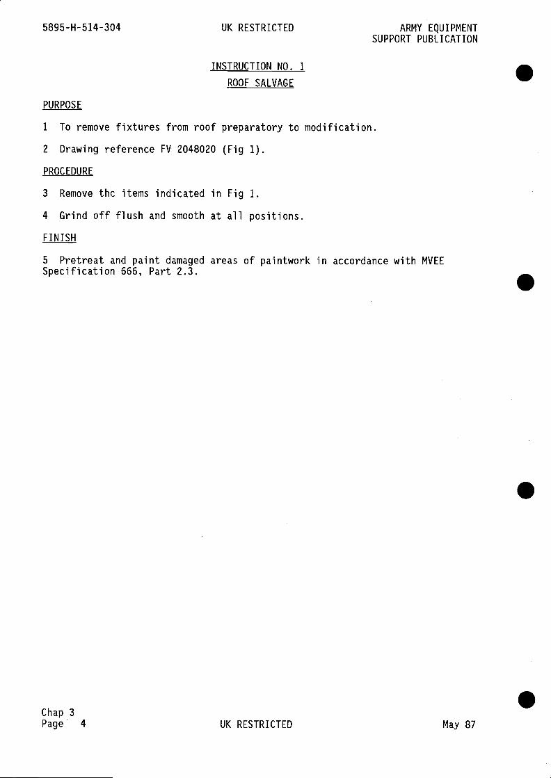
INSTRUCTION NO. 1
ROOF SALVAGE
PURPOSE
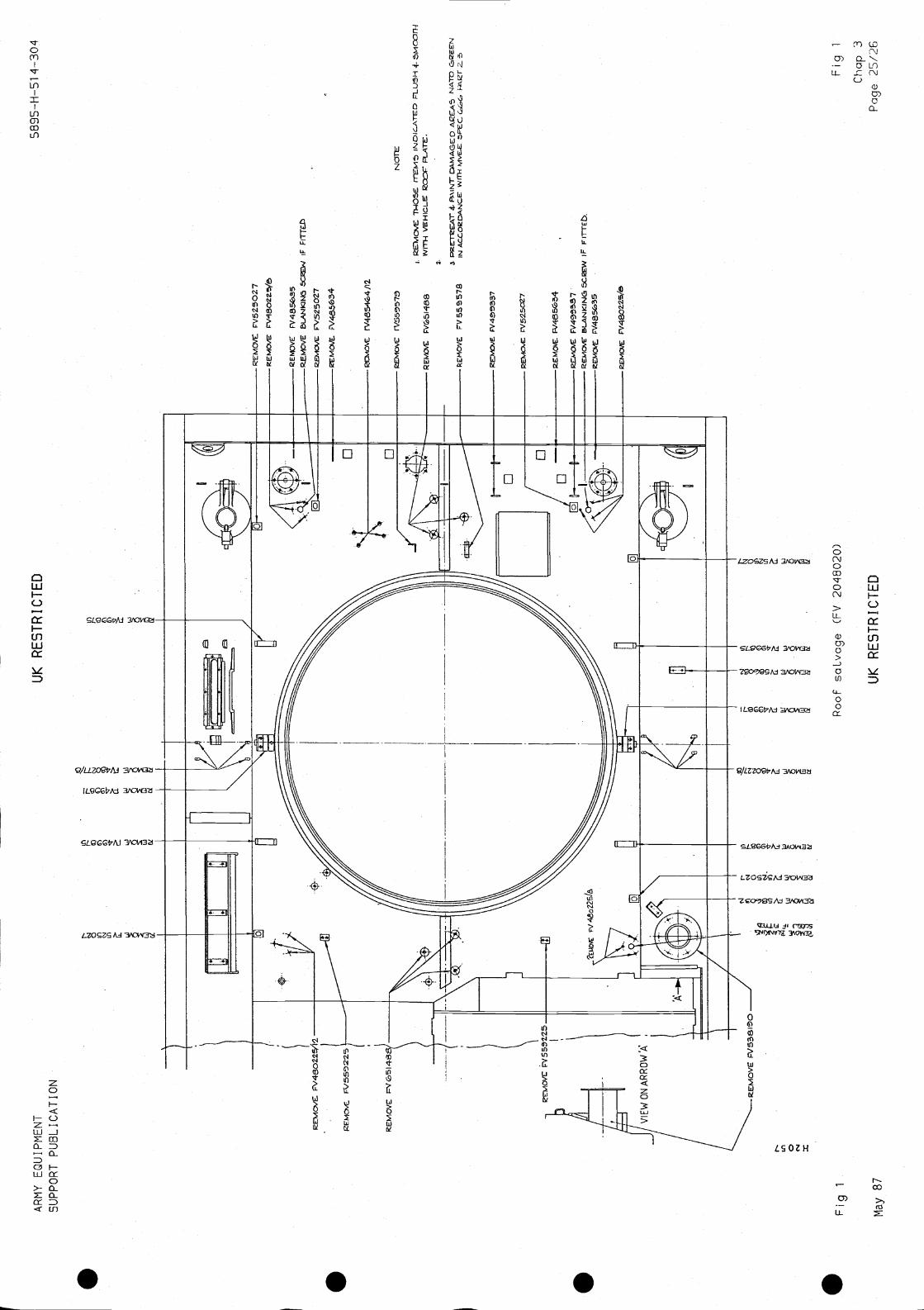
1 To remove fixtures from roof preparatory to modification.
2 Drawing reference FV 2048020 (Fig 1).
PROCEDURE
3 Remove thc items indicated in Fig 1.
4 Grind off flush and smooth at all positions.
FINISH
5 Pretreat and paint damaged areas of paintwork in accordance with MVEESpecification 666, Part 2.3.
.
.Chap 3Page 4 UK RESTRICTED May 87

ARMY EQUIPMENT UK RESTRICTED 5895-H-514-304SUPPORT PUBLICATION
INSTRUCTION NO. 2
ARMOURED HOUSING, APU MOUNTING, TURRET COVER PLATE
PURPOSE
1 To remove part of the wading screen and weld the items listed below to theroof.
2 Drawing references FV 2047984 (Fig 2)FV 2048020 (Fig 1)FV 602505 Hull welded assemblyFV 2047987 (Fig 4)
Note
Before commencing, ensure roof is cleared of items shown in Fig 1.
ITEMS REQUIRED
3 The following items are required from the Installation Kit:
ItemNo. NSN/FV No. Item Qty Remarks
4 FV 2047987 Plate, cover assembly 1
5 FV 2047988 Armoured housing assembly 1
6 FV 2048014 Skirt, APU mounting 1
8 FV 2047989 Boss, mounting 4
11 FV 498639 Rear blanking plate 2
15 FV 2048022 Adaptor bulkhead 1
17 FV 2048506 Backing strip 3
4 A fork lift truck or hoist will be required.
PROCEDURE
5 Refer to Fig 2 for details and proceed as in following paragraphs.
PLATE COVER ASSEMBLY
6 To weld the Plate Cover Assembly (4) in turret aperture:
6.1 Clean down to bare metal around turret ring on areas indicated inFig 3, sections A-A and F-F.
6.2 Fit the Plate cover assembly in the turret ring, studs/bosses toinside of vehicle.
6.3 Weld in position as detailed in Fig 2.
Chap 3May 87 UK RESTRICTED Page 5
5895-H-514-304 UK RESTRICTED ARMY EQUIPMENTSUPPORT PUBLICATION
SKIRT, APU MOUNTING
7 To fit the skirt (6) proceed as follows:
7.1 Prepare the area on RH side of roof to weld mounting to roof.
7.2 Position the skirt and check for level.
7.3 When level is achieved, tack weld in position and check.
7.4 Weld to roof as detailed in Fig 2.
7.5 Position and weld three backing strips (17) as detailed in Fig 2.
MISCELLANEOUS ITEMS
8 Before attempting to fit the Armoured Housing (5):
8.1 Remove the part of the wading screen indicated in Fig 2.
8.2 Weld Rear Blanking Plate (11) in position indicated at B in Fig 2 toclose end of wading screen.
8.3 Locate the 46/44 mm hole on LH sloping roof indicated in Fig 3(Section EE).
8.4 Clean off area around hole to 17 mm wide as in Fig 2.
8.5 Position Adaptor Bulkhead (15) over hole and tack weld.
8.6 Check alignment and fillet weld to roof.
8.7 Clean off around adaptor.
Note
The flat surface of the adaptor must be parallel to the centre line ofvehicle.
8.8 Clean off the area for the four bosses (8) to be welded on RH side ofroof as indicated in Fig 2.
8.9 Mark positions of the four bosses on the sloping part of roof.
8.10 Tack weld bosses in positions.
8.11 Check levels and correct as necessary.
8.12 Weld bosses to roof as detailed in Fig 2.
ARMOURED HOUSING ASSEMBLY
9 To fit the Armoured Housing (5):
9.1 Use a Fork lift or Hoist to position the Housing on the roof.
9.2 Clean off on LH side of roof in areas to be welded. .Chap 3Page 6 UK RESTRICTED May 87
ARMY EQUIPMENT UK RESTRICTEDSUPPORT PUBLICATION
9.3 Hoist the housing into position on roof as indicated in Fig 2. When
aligned and level, weld to roof as detailed in Fig 2.
FINISH
10 Clean off. Mask holes in bosses and pads. Pretreat and paint damagedareas of paintwork in accordance with MVEE Specification 666, part 2.3.Remove masking and apply grease XG 287 to holes in bosses and pads.
Chap 3May 87 UK RESTRICTED Page 7
5895-H-514-304 UK RESTRICTED ARMY EQUIPMENTSUPPORT PUBLICATION
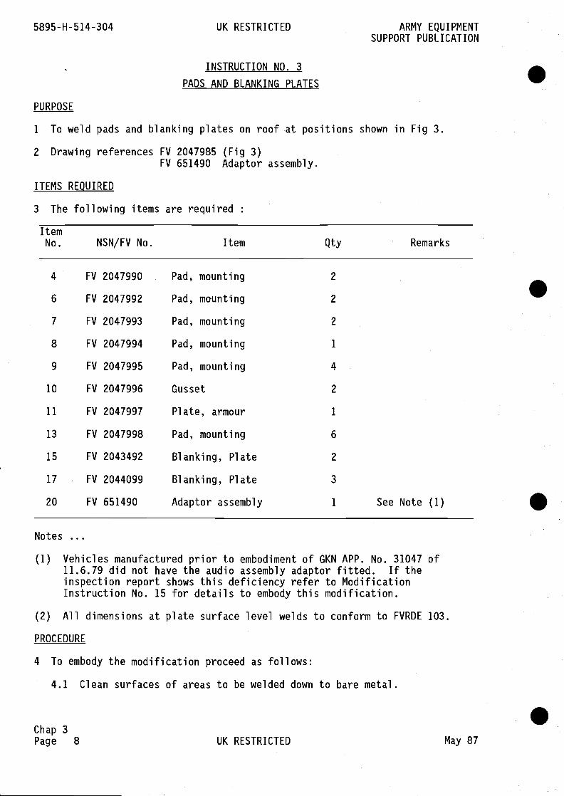
INSTRUCTION NO. 3
PADS AND BLANKING PLATES
PURPOSE
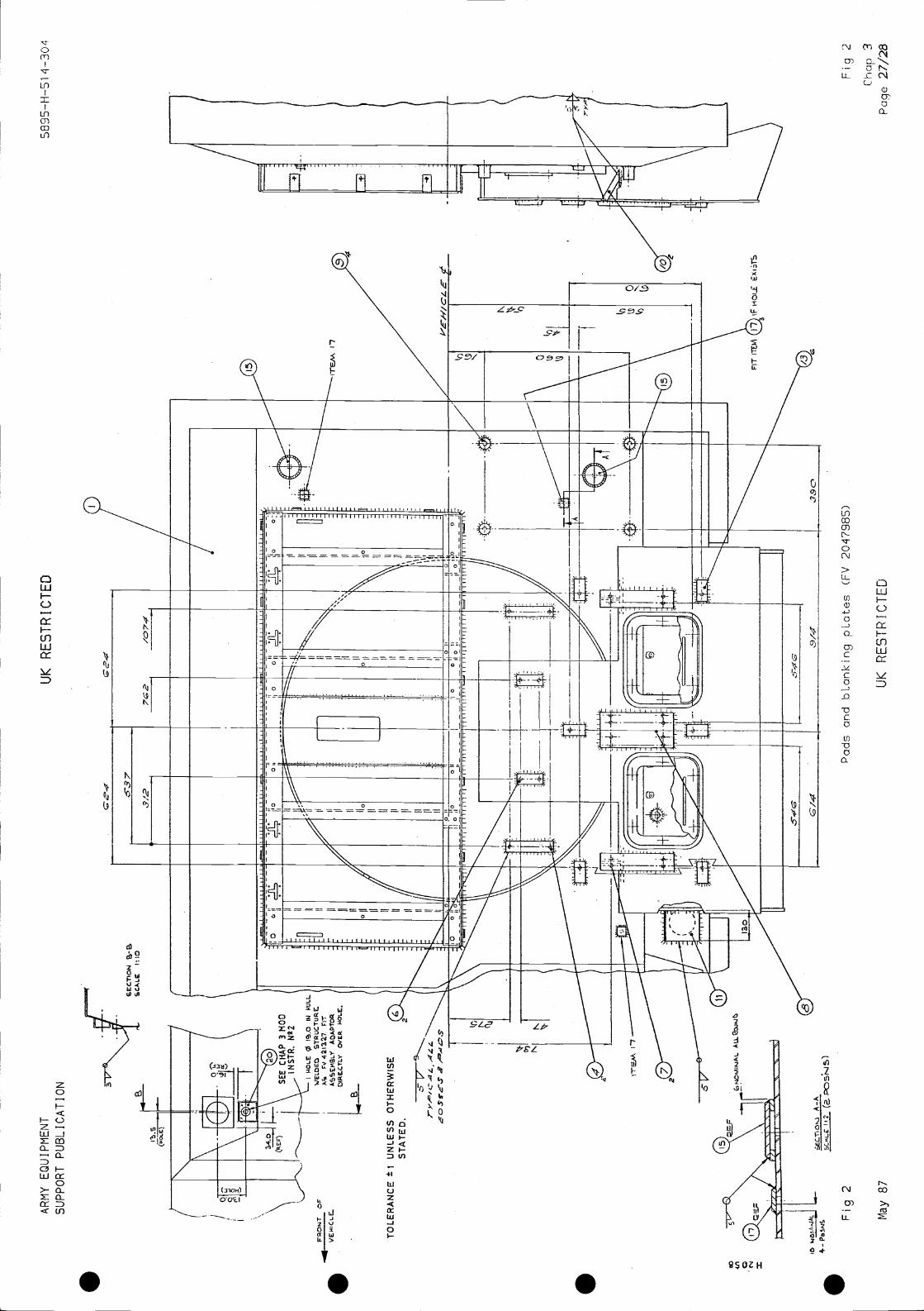
1 To weld pads and blanking plates on roof at positions shown in Fig 3.
2 Drawing references FV 2047985 (Fig 3)FV 651490 Adaptor assembly.
ITEMS REQUIRED
3 The following items are required
I ternNo. NSN/FV No. Item Qty Remarks
4 FV 2047990 Pad, mounting 2
6 FV 2047992 Pad,
mounting 2
FV Pad, mounting
FV Pad, mounting
FV 2
1
FV
FV 2
Plate
1 See Note (1)
Notes
(1) Vehicles manufactured prior to embodiment of GKN APP. No. 31047 of11.6.79 did not have the audio assembly adaptor fitted. If theinspection report shows this deficiency refer to ModificationInstruction No. 15 for details to embody this modification.
(2) All dimensions at plate surface level welds to conform to FVRDE 103.
PROCEDURE
4 To embody the modification proceed as follows:
4.1 Clean surfaces of areas to be welded down to bare metal.
Chap 3Page 8 UK RESTRICTED May 87
.
.
.
ARMY EQUIPMENT UK RESTRICTED 5895-H-514-304SUPPORT PUBLICATION
4.2 Tack weld pads (4,6,7,8,9,13) in position, item 9 threads uppermost,clean hole to vehicle roof.
4.3 Check alignment and levels, correct as necessary.
4.4 Weld pads to roof as detailed in Fig 3.
4.5 Referring to Note (1) above, if hole exists for the audio assemblyadaptor, weld blanking plates (15 and 17) in position as shown in Fig 3.
4.5.1 Fit audio assembly adaptor (20).
4.6 Fit and weld plate armour (11) on LH side front of armoured housing asshown in Fig 3.
4.7 Weld two gussets (10) to roof as detailed in Fig 3.
FINISH
5 Mask holes in bosses and blanking plates.
6 Pretreat all damaged areas of paintwork.
7 Paint in accordance with MVEE Specification 666, Part 2,3.
8 Remove masking and apply grease XG 287 to threaded holes.
Chap 3May 87 UK RESTRICTED Page 9
11
12as
13
FINISH
14
15
16
17
Chap 3Page 10
ARMY EQUIPMENTSUPPORT PUBLICATION
5895-H-514-304 UK RESTRICTED
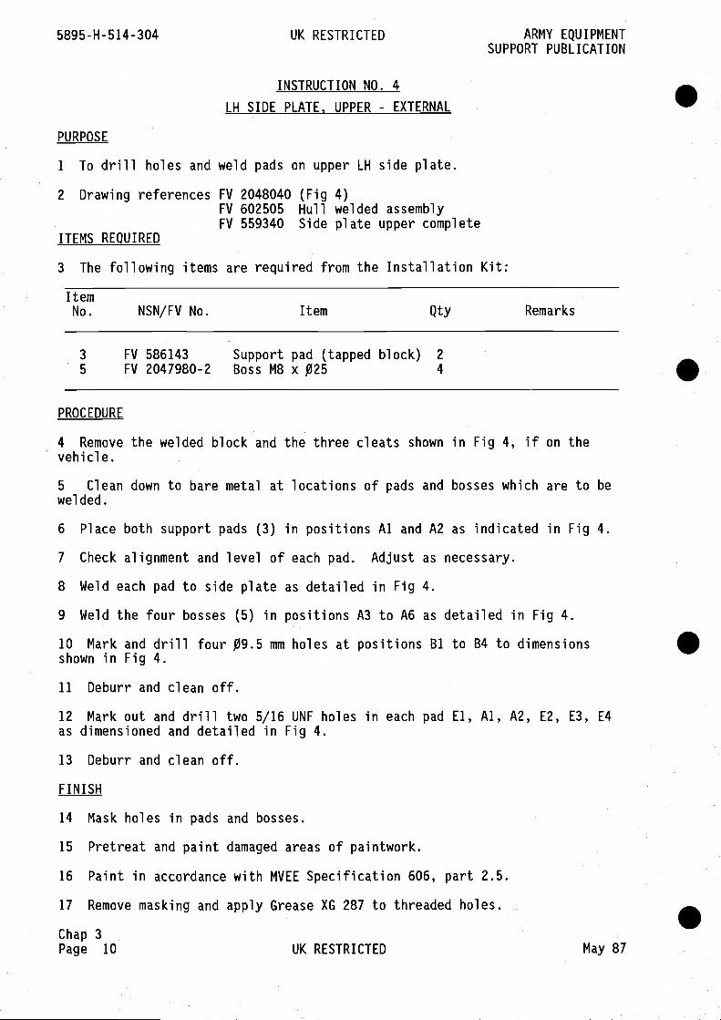
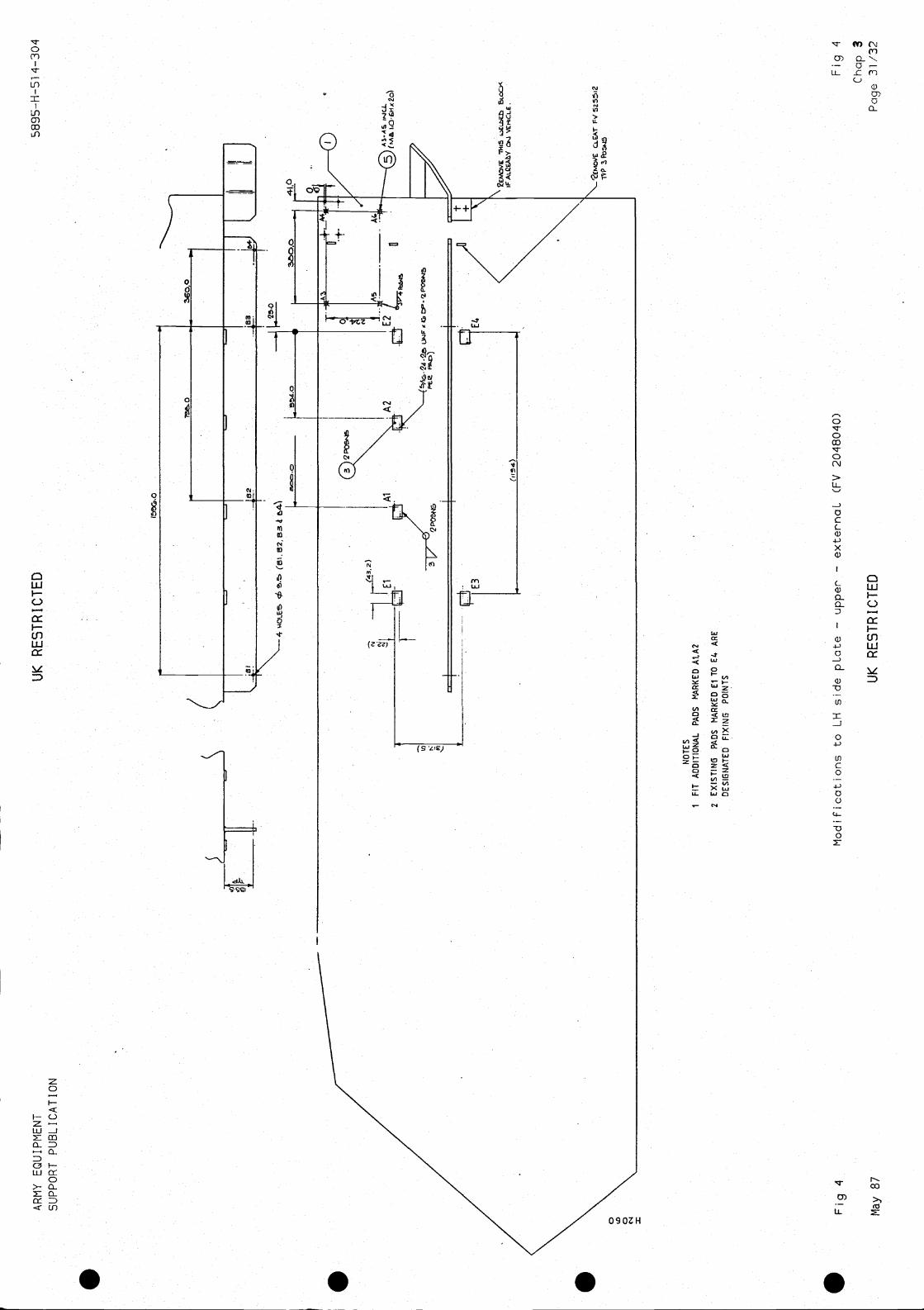
INSTRUCTION NO. 4
LH SIDE PLATE, UPPER - EXTERNAL
PURPOSE
1 To drill holes and weld pads on upper LH side plate.
2 Drawing references FV 2048040 (Fig 4)FV 602505 Hull welded assemblyFV 559340 Side plate upper complete
ITEMS REQUIRED
3 The following items are required from the Installation Kit:
ItemNo. NSN/FV No. Item Qty Remarks
3 FV 586143 Support pad (tapped block) 2
5 FV 2047980-2 Boss M8 x 025 4
.
S
S
S
PROCEDURE
4 Remove the welded block and the three cleats shown in Fig 4, if on thevehicle.
5 Clean down to bare metal at locations of pads and bosses which are to bewelded.
6 Place both support pads (3) in positions Al and A2 as indicated in Fig 4.
7 Check alignment and level of each pad. Adjust as necessary.
8 Weld each pad to side plate as detailed in Fig 4.
9 Weld the four bosses (5) in positions A3 to A6 as detailed in Fig 4.
10 Mark and drill four 09.5 mm holes at positions B1 to B4 to dimensionsshown in Fig 4.
Deburr and clean off.
Mark out and drill two 5/16 UNF holes in each pad El, Al, A2, E2, E3, E4dimensioned and detailed in Fig 4.
Deburr and clean off.
Mask holes in pads and bosses.
Pretreat and paint damaged areas of paintwork.
Paint in accordance with MVEE Specification 606, part 2.5.
Remove masking and apply Grease XG 287 to threaded holes.
UK RESTRICTED May 87

ARMY EQUIPMENT UK RESTRICTED 5895-H-514-304SUPPORT PUBLICATION
INSTRUCTION NO. 5
ROOF PLATE, LH SIDE - INTERNAL
PURPOSE
1 To fit bosses in ten positions on roof plate.
2 Drawing references FV 2048509 (Fig 5)FV 602505 Hull welded assemblyFV 5597781 Roof plate side LH complete
ITEMS REQUIRED
3 The following items are required from the Installation Kit:
ItemNo. NSN/FV No. Item Qty Remarks
3 FV 208216-1 Boss M6 x 020 x 10 long 10
PROCEDURE
4 Clean down to bare metal at boss and cleat positions.
5 Mark boss positions on roof plate.
6 Tack weld bosses at positions Al to AlO as detailed in Fig 5.
7 Check alignment and level of bosses, correct as necessary.
8 Weld bosses to roof as detailed In Fig 5.
9 Remove cleat from position shown in Fig 5 and grind off flush end smooth.
FINISH
10 Mask holes in bosses before painting.
11 Pretreat damaged areas of paintwork and paint in accordance with MVEESpecification 666, part 2.5.
12 Remove masking and apply Grease XG 287 to threaded holes in bosses.
Chap 3May 87 UK RESTRICTED Page 11
ItemNo. NSN/FV No. Item Qty Remarks
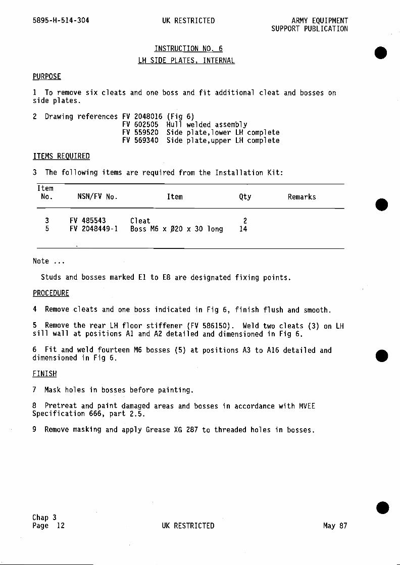
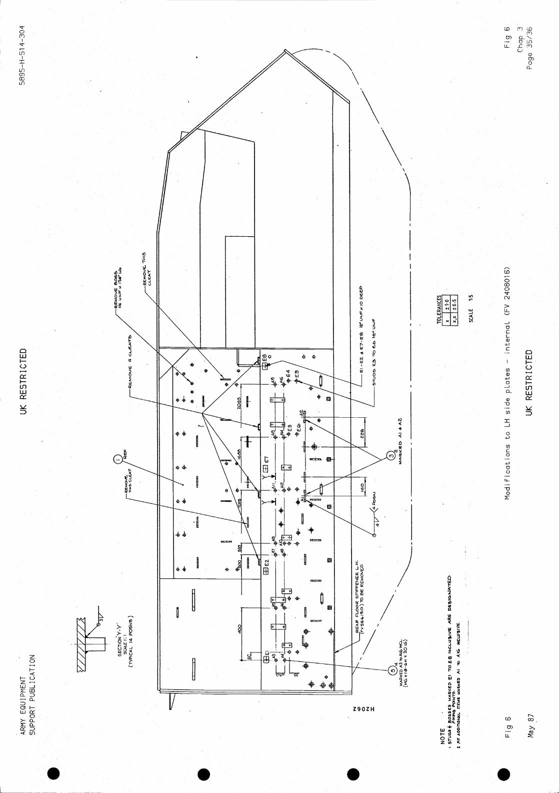
3 FV 485543 Cleat 2
5 FV 2048449-1 Boss M6 x x 30 long 14
Note
Studs and bosses marked El to E8 are designated fixing points.
PROCEDURE
4 Remove cleats and one boss indicated in Fig 6, finish flush and smooth.
5 Remove the rear LH floor stiffener (FV 586150). Weld two cleats (3) on LHsill wall at positions Al and A2 detailed and dimensioned in Fig 6.
6 Fit and weld fourteen M6 bosses (5) at positions A3 to A16 detailed anddimensioned in Fig 6.
FINISH
7 Mask holes in bosses before painting.
8 Pretreat and paint damaged areas and bosses in accordance with MVEESpecification 666, part 2.5.
9 Remove masking and apply Grease XG 287 to threaded holes in bosses.
Chap 3Page 12 UK RESTRICTED May 87
5895-H-514-304 UK RESTRICTED ARMY EQUIPMENTSUPPORT PUBLICATION
INSTRUCTION NO. 6
LH SIDE PLATES, INTERNAL
PURPOSE
1 To remove six cleats and one boss and fit additional cleat and bosses onside plates.
2 Drawing references FV 2048016 (Fig 6)FV 602505 Hull welded assemblyFV 559520 Side plate,lower LH completeFV 569340 Side plate,upper LH complete
ITEMS REQUIRED
3 The following items are required from the Installation Kit:
.
.
.
ARMY EQUIPMENT UK RESTRICTED 5895-H-514-304SUPPORT PUBLICATION
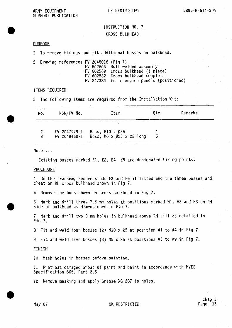
INSTRUCTION NO. 7
CROSS BULKHEAD
PURPOSE
1 To remove fixings and fit additional bosses on bulkhead.
2 Drawing references FV 2048018 (Fig 7)FV 602505 Hull welded assemblyFV 602569 Cross bulkhead (1 piece)FV 602562 Cross bulkhead completeFV 847384 Frame engine panels (positioned)
ITEMS REQUIRED
3 The following items are required from the Installation Kit:
ItemNo. NSN/FV No, Item Qty Remarks
2 FV 2047979-1 Boss, M1O x 4
3 FV 2048450-1 Boss, M6 x 025 x 25 long 5
Note
Existing bosses marked El, E2, [4, E5 are designated fixing points.
PROCEDURE
4 On the transom, remove studs E3 and E6 if fitted and the three bosses andcleat on RH cross bulkhead shown in Fig 7.
5 Remove the boss shown on cross bulkhead in Fig 7.
6 Mark and drill three 7.5 mm holes at positions marked Hi, H2 and H3 on RHside of bulkhead as dimensioned in Fig 7.
7 Mark and drill two 9 mm holes in bulkhead above RH sill as detailed inFig 7.
8 Fit and weld four bosses (2) M10 x 25 at position Al to A4 in Fig 7.
9 Fit and weld five bosses (3) M6 x 25 at positions A5 to A9 in Fig 7.
FINISH
10 Mask holes in bosses before painting.
11 Pretreat damaged areas of paint and paint in accordance with MVEESpecification 666, Part 2.5.
12 Remove masking and apply Grease XG 287 to holes.
Chap 3May 87 UK RESTRICTED Page 13

5895-H-514-304 UK RESTRICTED ARMY EQUIPMENTSUPPORT PUBLICATION
INSTRUCTION NO. 8
RH SIDE PLATE - INTERNAL
PURPOSE
1 To remove items and fit additional bosses and bracket.
2 Drawing references FV 2048017 (Fig 8)FV 559487 Side plate lower RH completeFV 559384 Cross bulkhead, complete
ITEMS
3 The following items are required
I ternNo. NSN/FV No. Item Qty Remarks
3 FV 2048449-1 Boss6H x
M6
30x 1.0long
- 10 Blind thread
5 FV 2048872 Bracket 1
Note
Bosses, studs and cleats marked El to E12 are designated fixing points.
PROCEDURE
4 Remove and discard existing cover plate to FV 524767 at rear of RH sillwall.
5 Remove and discard floor stiffener RH plate FV 524747.
6 Remove the two cleats on RH sill indicated in Fig 8.
7 Fit and weld M6 bosses (3) in ten positions Al to AlO.
8 Weld bracket (5) on RH sill wall as shown in Fig 8.
9 Mark and drill one 012 mm hole in the bracket as detailed in Fig 8(Section A-A).
FINISH
10 Mask holes in bosses and bracket before painting.
11 Pretreat damaged areas and paint in accordance with MVEE Specification666, Part 2.5.
12 Remove masking and apply Grease XG 287 to holes.
Note
For information only. The replacement cover plate is FV 2048383.
Chap 3Page 14 UK RESTRICTED May 87
.
.
.
ARMY EQUIPMENT UK RESTRICTED 5895-H-514-304SUPPORT PUBLICATION
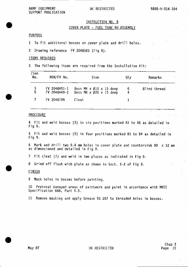
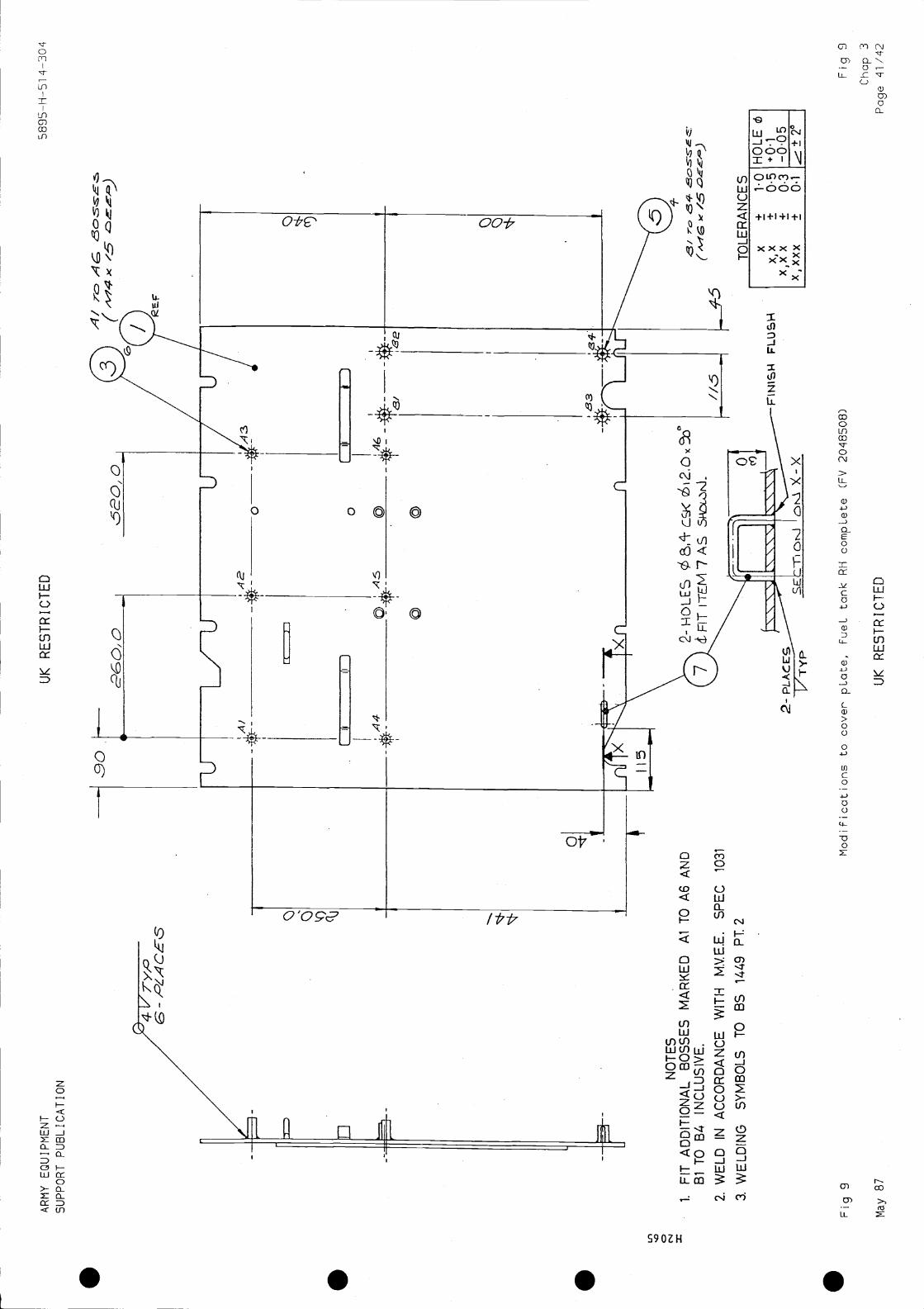
INSTRUCTION NO. 9
COVER PLATE FUEL TANK RH ASSEMBLY
PURPOSE
1 To fit additional bosses on cover plate and drill holes.
2 Drawing reference FV 2048505 (Fig 9).
ITEMS REQUIRED
3 The following items are required from the Installation Kit:
ItemNo. NSN/FV No. Item Qty Remarks
3 FV 2048451-1 Boss M4 x 015 x 15 deep 6 Blind thread5 FV 2048449-2 Boss M6 x 020 x 15 deep 4
7 FV 2048198 Cleat 1
PROCEDURE
4 Fit and weld bosses (3) in six positions marked Al to A6 as detailed inFig 9.
5 Fit and weld bosses (5) in four positions marked BI to B4 as detailed inFig 9.
6 Mark and drill two 8.4 mm holes in cover plate and countersink 90 x 12 mmas dimensioned and detailed in Fig 9.
7 Fit cleat (7) and weld in two places as indicated in Fig 9.
8 Grind off flush with plate as shown in Sect. X-X of Fig 9.
FINISH
9 Mask holes in bosses before painting.
10 Pretreat damaged areas of paintwork and paint in accordance with MVEESpecification 666, Part 4.5.
11 Remove masking and apply Grease XG 287 to threaded holes in bosses.
Chap 3May 87 UK RESTRICTED Page 15
5895-H-514-304 UK RESTRICTED ARMY EQUIPMENTSUPPORT PUBLICATION
INSTRUCTION NO. 10
FUEL TANK END PROTECTION PLATE. COMPLETE, RH
PURPOSE
1 To remove and fit additional bosses and remove one cleat.
2 Drawing references FV 2048663 (Fig 10)
ITEMS REQUIRED
3 The following items are required from the Installation Kit:
I ternNo. NSN/FV No. Item Qty Remarks
3 FV 485463/14 Tapped boss 2 .PROCEDURE
4 Remove the cleat from position shown in Fig 10 and grind flush withsurrounding area.
5 Remove the four bosses shown in Fig 10 and grind flush and smooth withsurrounding area.
6 Fit and weld two additional bosses in positions Al and A2 as dimensionedand indicated in Fig 10.
FINISH
7 Mask holes in bosses before painting.
8 Pretreat damaged areas of paintwork and paint in accordance with MVEESpecification 666, Part 4.5.
9 Remove masking and apply Grease XG 287 to threaded holes in bosses.
.Chap 3Page 16 UK RESTRICTED May 87
ARMY EQUIPMENT UK RESTRICTED 5895-H-514-304SUPPORT PUBLICATION
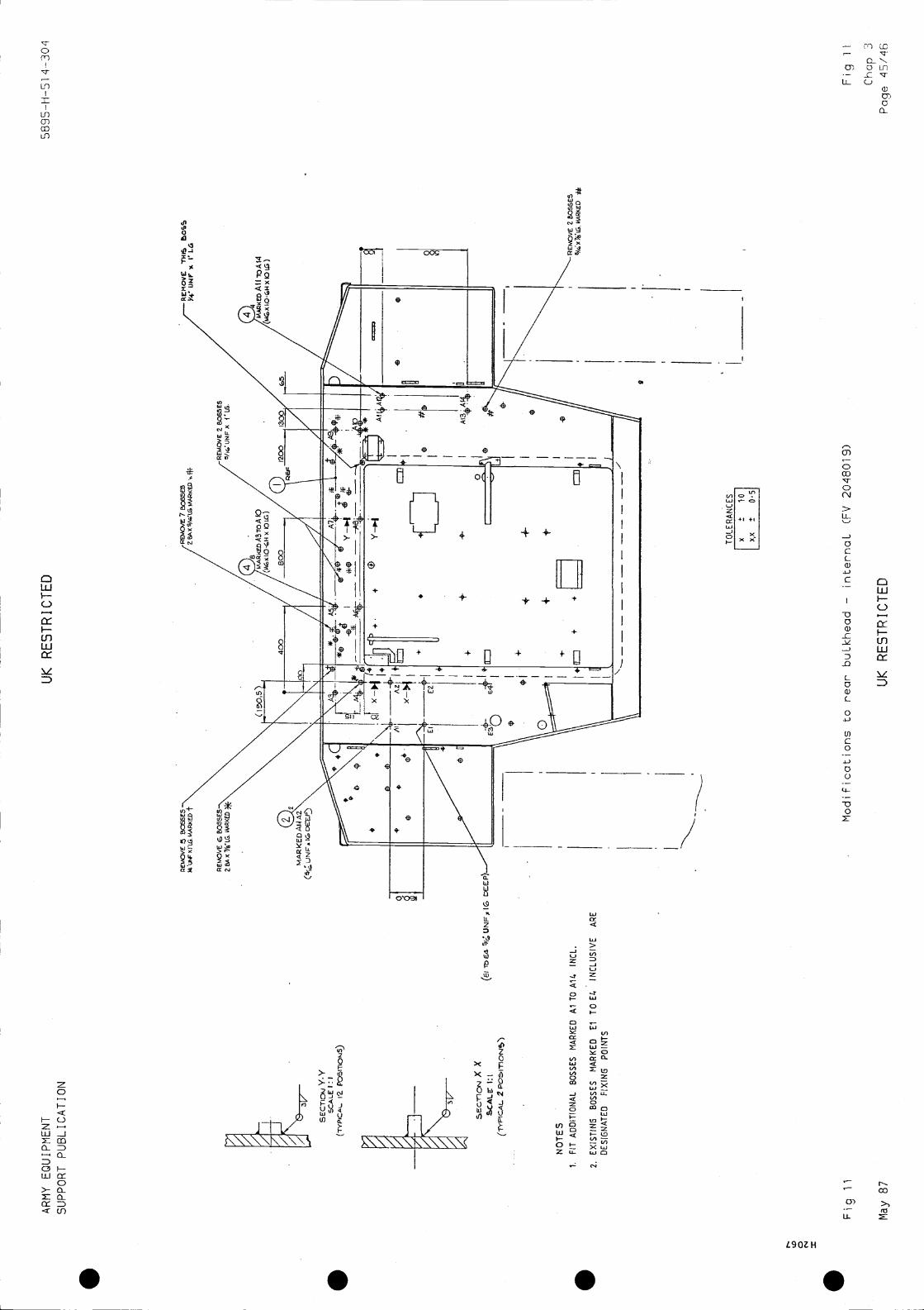
INSTRUCTION NO. 11
REAR BULKHEAD INTERNAL
PURPOSE
1 To remove fixings and fit additional bosses.
2 Drawing references FV 2048019 (Fig 11)FV 559402 Rear Plate completeIV 602505 Hull welded assemblyFV 602569 Cross bulkhead, 1 pieceFV 602562 Cross bulkhead completeIV 847384 Frame engine panels (positioned)
ITEMS REQUIRED
3 The following items are required from the Installation Kit:
I ternNo. NSN/FV No. Item Qty Remarks
2 FV 485465/14 Boss 5/16 UNF x 7/8 long 2
4 FV 2048216-1 Boss M6 x x 10 long 12
Note
Existing bosses marked El to E4 are designated fixing points.
PROCEDURE
4 Remove the 23 bosses indicated in Fig 11.
5 Fit and weld two 5/16 UNF bosses (2) in positions Al and A2 as detailed inFig 11.
6 Fit and weld M6 bosses (4) in twelve positions A3 to A14 as detailed inFig 11.
FINISH
7 Mask holes in bosses before painting.
8 Pretreat damaged areas of paint and paint in accordance with MVEESpecification 666, Part 2.5.
9 Remove masking and apply grease XG 287 to threaded holes in bosses.
Chap 3May 87 UK RESTRICTED Page 17
5895-H-514-304 UK RESTRICTED ARMY EQUIPMENTSUPPORT PUBLICATION
PURPOSE
INSTRUCTION NO. 12
ROOF - INTERNAL
1 To remove 23 bosses and fit additional bosses.
.2 Drawing references FV 2048015 (Fig 12)
FV 602505 Hull welded assemblyFV 559510 Sheet 2 Roof plate, rear, centre complete
ITEMS REQUIRED
3 The following items are required from the Installation Kit:
ItemNo. NSN/FV No. Item Qty Remarks
2
3
4
5
7
FV
FV
FV
FV
FV
2047980-12047981-1
2048216-12048216-22047980-3
Boss M8 x x 32 longBoss in. UNF x 040 x19 longBoss M6 x 020 x 10 longBoss M6 x 020 x 20 longBoss M8 x 025 x 15 long
2
3
6
82
9 FV 123983 Boss 5/16 UNF x 5/8 in.long
2
12
14
FV 485465/14 Boss 5/16 in. UNF x7/8 in. longConductive paint system
2
A/R CONDUCTO
ThinnersCOATT-335
981
Note
Existing bosses marked El to E21 are designated fixing points.
PROC EDURE
4 Remove all air duct trunking from the RH side of the section of roof torear of vehicle and the aft section of air duct (1220 m long) on the rearLH side, as indicated in Fig 12.
5 Remove the four bosses and stud indicated in Fig 12 from the roof plate.
6 Fit the following bosses on roof plate as detailed in Fig 12.
6.1 Weld M8 bosses (2) in two positions A4 and A5 as detailed in Fig 12.
6.2 Weld in. UNF bosses (3) in three positions marked Al to A3 on the RHside of roof plate.
6.3 Weld M6 bosses (4) in two positions marked A6 and A7 on LH side ofroof plate and in four positions marked A9 to A12 on RH side of roof plate.
Chap 3Page 18 UK RESTRICTED May 87
.
.
.
ARMY EQUIPMENT UK RESTRICTED 5895-H-514-304SUPPORT PUBLICATION
6.4 Weld M8 bosses (5) in four positions marked A13 to A16 and in fourpositions marked A17 to A20 on rear part of roof plate.
6.5 Weld (3 mm fillet) M8 bosses (7) in two positions marked on roofplate forward of hatch.
6.6 Weld 5/16 in. UNF bosses (9) in two positions marked * on roof plateforward of hatch.
6.7 Weld 5/16 in. UNF bosses (12) in two positions marked A21 and A22 onrear part of roof plate.
7 On the hatched areas shown in Fig 12 remove existing paint and clean tobare metal (see Para 9 below).
8 On the LH side of roof plate clean to bare metal the hatched area aroundthe 32 mm hole on the LH side of roof plate (Fig 12) to a width of 55 mm
WARNING
HEALTH HAZARD. CONDUCTIVE PAINT (ITEM 14) MAY BE INJURIOUS TO HEALTH.
PRECAUTIONS RECOMMENDED BY THE PAINT MANUFACTURER MUST BE TAKEN.
9 Paint the cleaned hatched areas using the proprietary paint system(item 14).
Note
Clean in accordance with Defence Standard 03-2/1, Method D where necessaryand method A] or A2.
FINISH
10 Mask holes in bosses before painting.
11 Pretreat damaged areas of paintwork around all additional bosses andpaint in accordance with MVEE Specification 660 Part 2.5.
12 Remove masking and apply Grease XG 287 to threaded holes in bosses.
Chap 3May 87 UK RESTRICTED Page 19

5895-H- 514-304 UK RESTRICTED ARMY EQUIPMENTSUPPORT PUBLICATION
PURPOSE
INSTRUCTION NO. 13
PANNIER PLATE LH
1 To fit additional bosses.fixing points.
Existing bosses marked El to E9 are designated
2 Drawing references FV 2048507 (Fig 13)FV 559358 Assembly of welded hullFV 602505 Hull welded assembly
ITEMS REQUIRED
3 The following items are required from the Installation Kit:
I ternNo. NSN/FV No. Item Qty Remarks
3 FV 2048450-2 Boss M6 x 025 5.
PROCEDURE
4 Fit and weld five bosses (3) in positions Al to A5 as detailed in Fig 13.
NoteExisting bosses marked El to E9 are designated fixing points.
FINISH
5 Mask holes in bosses before painting.
6 Pretreat damaged areas of paintwork and pain in accordance with MVEESpecification 666, Part 2.5.
7 Remove masking and apply Grease XG 287 to threaded holes in bosses.
Chap 3Page 20 UK RESTRICTED May 87
.
.
.

ARMY EQUIPMENT UK RESTRICTED 5895-H-514-304SUPPORT PUBLICATION
INSTRUCTION NO. 14
FLOOR - INTERNAL
PURPOSE
1 To fit floor plate and boss mountings.
2 Drawing references FV 2048024 (Fig 14)FV 602505 Hull welded assembly
ITEMS REQUIRED
3 The following items are required from the installation kit.
ItemNo. NSN/FV No. Item Qty Remarks
3 FV 2048042 Plate, mounting floor 1
4 FV 2048043 Boss, mounting 12
PROCEDURE
4 Remove all floor plates if not previously removed.
Notes
(1) Welding to conform to MVEE Specification 1031 and symbols to BS 499Part 2.
(2) Welds to be positioned centrally on floor members as shown in eightplaces in Fig 14.
(3) Permitted tolerance between holes must not be greater than 1.0 mm,
(4) The datum references are indicated in Fig 14,
(5) Use templates manufactured from drawings in Chap 2, Figs 1 and 2.
5 Mark and drill one hole 20.0 mm diameter in floor member at rear RH ofcentre as detailed in Fig 14 to provide clearance for the anchor nut head whenthe plate (3) is fitted.
Chap 3May 87 UK RESTRICTED Page 21
5895-H-514-304 UK RESTRICTED ARMY EQUIPMENTSUPPORT PUBLICATION
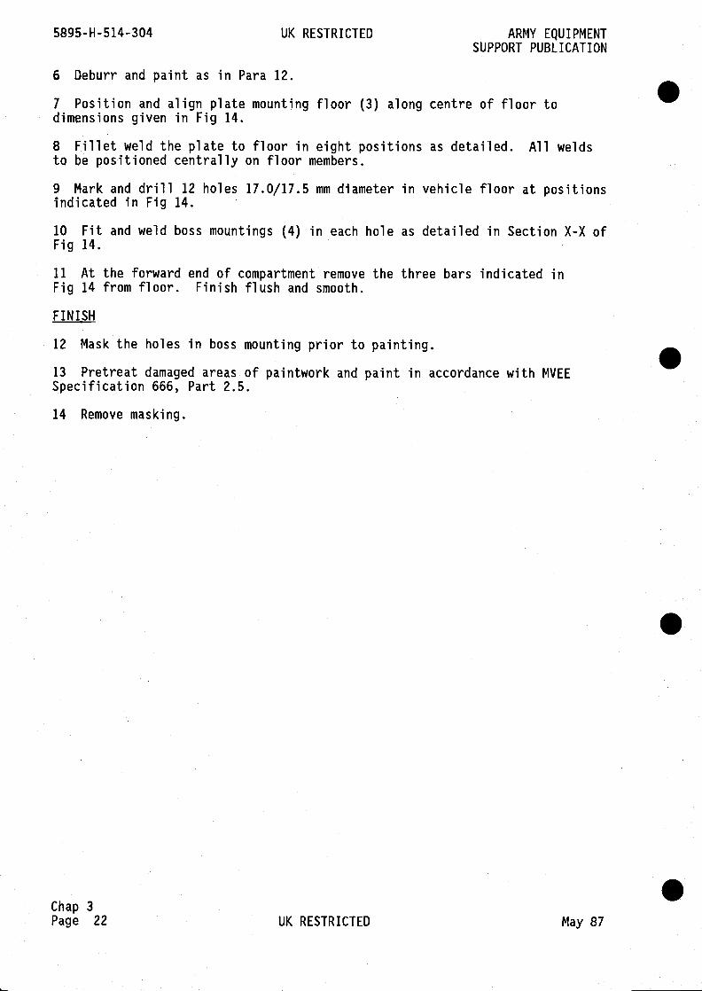
6 Deburr and paint as in Para 12.
7 Position and align plate mounting floor (3) along centre of floor todimensions given in Fig 14.
8 Fillet weld the plate to floor in eight positions as detailed. All weldsto be positioned centrally on floor members.
9 Mark and drill 12 holes 17.0/17.5 mm diameter in vehicle floor at positionsindicated in Fig 14.
10 Fit and weld boss mountings (4) in each hole as detailed in Section X-X ofFig 14.
11 At the forward end of compartment remove the three bars indicated inFig 14 from floor. Finish flush and smooth.
FINISH
12 Mask the holes in boss mounting prior to painting.
13 Pretreat damaged areas of paintwork and paint in accordance with MVEESpecification 666, Part 2.5.
14 Remove masking.
.
.Chap 3Page 22 UK RESTRICTED May 87
ARMY EQUIPMENT UK RESTRICTED 5895-H-5i4-304SUPPORT PUBLICATION
INSTRUCTION
AUDIO ADAPTOR ASSEMBLY
PURPOSE
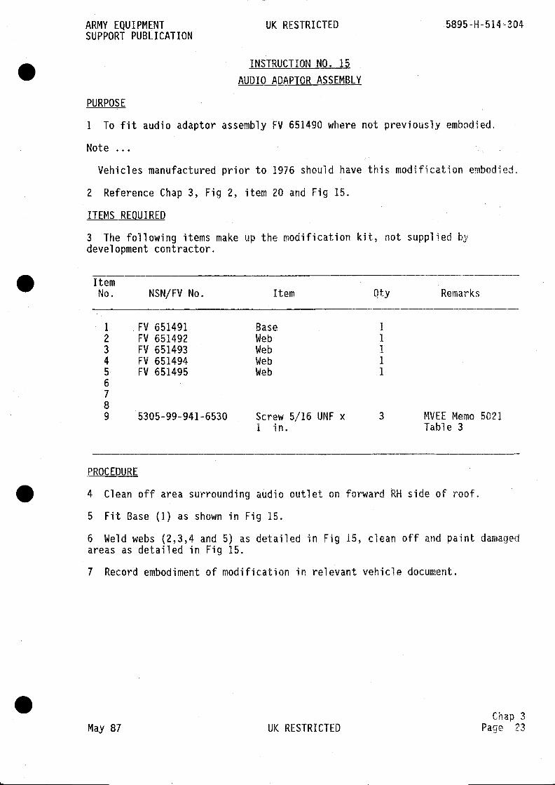
1 To fit audio adaptor assembly FV 651490 where not previously embodied.
Note
Vehicles manufactured prior to 1976 should have this modification embodied.
2 Reference Chap 3, Fig 2, item 20 and Fig 15.
ITEMS REOUIRED
3 The following items make up the modification kit, not supplied bydevel opment contractor.
ItemNo. NSN/FV No, Item Qty Remarks
1 FV 651491 Base 1
2 FV 651492 Web I3 FV 651493 Web 1
4 FV 651494 Web 1
5 FV 651495 Web 1
67
89 5305-99-941-6530 Screw
I in.5/16 UNF x 3 MVEE
TableMemo
3
5021
PROCEDURE
4 Clean off area surrounding audio outlet on forward RH side of roof.
5 Fit Base (1) as shown in Fig 15.
6 Weld webs (2,3,4 and 5) as detailed in Fig 15, clean off and paint damagedareas as detailed in Fig 15.
7 Record embodiment of modification in relevant vehicle document.
chap 3
May 87 UK RESTRICTED Page 23

5895-H-514-304 UK RESTRICTED ARMY EQUIPMENTSUPPORT PUBLICATION
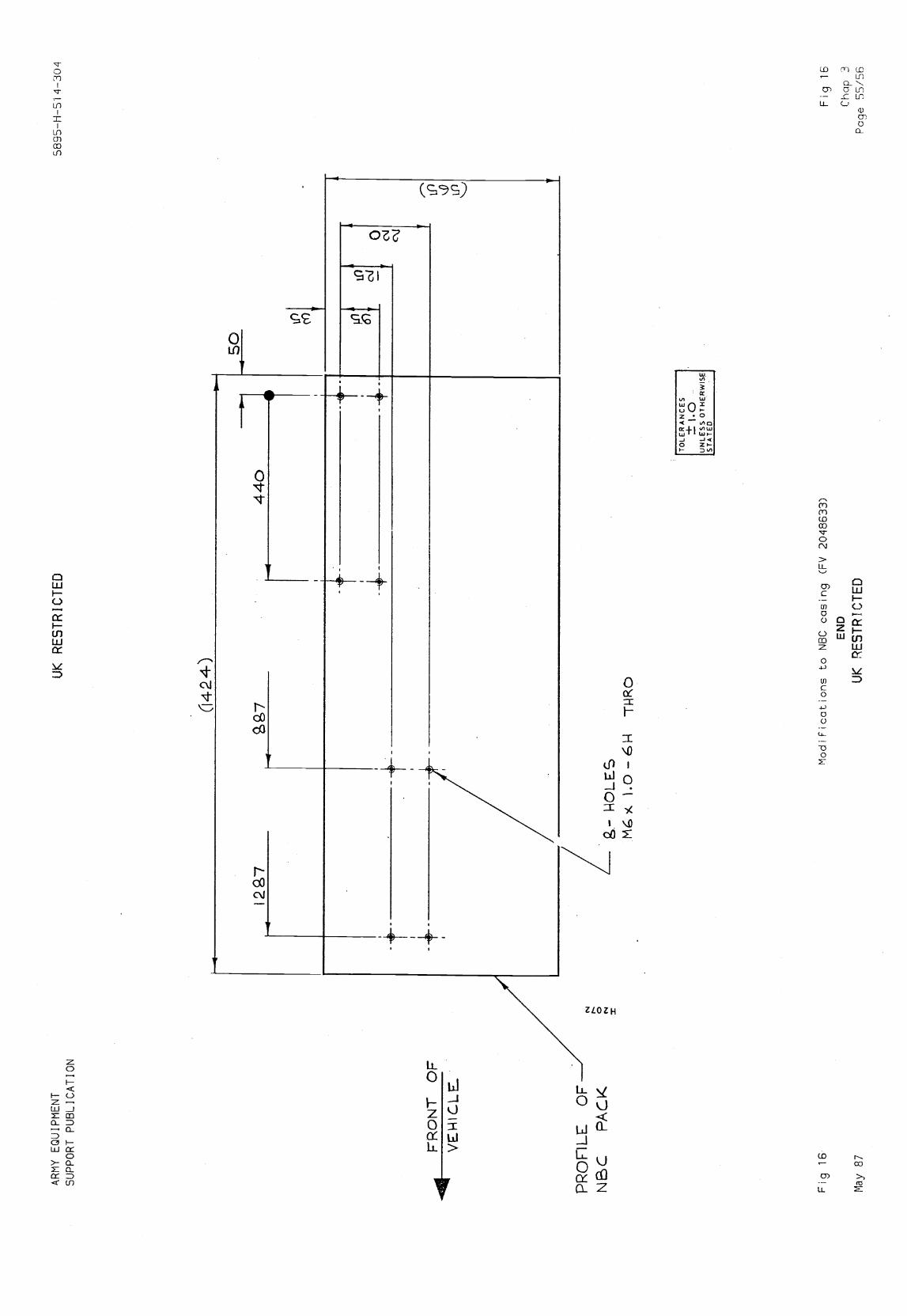
INSTRUCTION NO. 16
NBC UNIT CASING
PURPOSE
1 To drill four holes in two positions in NBC casing.
2 Drawing reference FV 2048633 (Fig 16)FV 2048017 (Fig 8)
PROCEDURE
3 Mark and drill four M6 holes in two positions and tap 1.0 x 6H through asdetailed in Fig 16.
S
S
.Chap 3Page 24 UK RESTRICTED May 87
ARMY EQUIPMENT
UK
RE
ST
RIC
TE
D58
95-H
-51
4-30
4
SU
PP
OR
T P
UB
LIC
AT
ION
iF
FV
5250
27
r148
54co
4/iz
FVIN F
F
1R
oof s
aLva
ge (
FV
2048020)
May 87
UK
RE
ST
RIC
TE
D
Fig
1
Chap
:3
Pag
e
If)

. . . .
AR
MY
EQ
UIP
ME
NT
UK
RE
ST
RIC
TE
D58
95—
H--
51 4
-304
SU
PP
OR
T P
UB
LIC
AT
ION
Fig
2
May
87
SEE CHAP 3 HOD
INSTR. N22
I14
0LE
N II
ULL
ST
RU
C.T
UR
EF
IT
A-A
SC
ALE
1:10
637
/07-
ct
/\
/
14a
TOLERANCE ±1 UNLESS OTHERWISE
STATED.
\
- o
II
0
UI
0
II
— II II ii II 11
0
II II II
II II I!
I
ft
10
I'
II 0
0I0
\\
£1__
-I
/4
9'
0
0
IL
L
'
GY
4
FIT
hell
Pads and bLanking
pLat
es (
FV
204
7985
)
UK
RE
ST
RIC
TE
D
Fig
:2
Cha
p 3
Pag
e 27
/28

. . . .

AR
MY
EQ
UIP
ME
NT
UK
RE
ST
RIC
TE
D58
95—
H—
51 4
-304
SU
PP
OR
T P
UB
LIC
AT
ION
0' NJ =
SE
CT
ION
0-0
3
Ith
oil
A]
/'//5
0/5
0
G
/8
Fjg
3
May
87
Mod
ifcat
]ons
to r
oof —
ext
erna
L (F
V 2
0479
B4)
UK
RE
ST
RIC
TE
D
Fiq
3
Cha
p 3
Pag
e 2W
30
.4 _
9 _c
f-3
-30
BE
FO
RE
CO
MM
EN
CIN
G W
OR
K S
HO
WN
ON
TH
IS D
RA
WIN
G R
EF
ER
TO
FIG
1
TO
LER
AN
CE
±1
UN
LES
S O
TH
ER
WIS
ES
TA
TE
D.
/r
L
Ot
if 0
0
-4- t/
ICo d
Nt
Li L
iL
-it-
5
c--C
7-ca
/:/
5EC
TIO
F'J
E. -
E
NS
/'i5
0 C
4CF
,1'5
ro a
dC
c ro
.-c,
wcc
C
0)0)
,-3
///
N
.4 -
.4
•N
1-I-
H
_L /90
/50 3.47
-
850
OP SC
PE
EN
£/$I
WQ
4
FLA
TN
ES
S R
EQ
UIR
ED
IN S
HA
OE
D A
RE
A

. . . .
UK
RE
ST
RIC
TE
D
3
A2
'CD
PE
Z
0 to 0
NO
TE
S1
FIT
AD
DIT
ION
AL
PA
DS
MA
RK
ED
A1,
A2
2E
XIS
TIN
GP
AD
S M
AR
KE
D E
l TO
E4
AR
ED
ES
IGN
AT
ED
FIX
ING
PO
INT
S
'&M
OV
E C
LE
AT
iVP
Fjg 4
May 87
Modifications to LH side pLate —
uppe
r—
UK
RE
ST
RIC
TE
D
externaL (FV 2048040)
Fig 4
Chap 3
Page
31/32
ARMY EQUIPMENT
SU
PP
OR
T P
US
LIC
AT
ION
.5895-H-Si 4-304
1TftS
iF

. . . .

AR
MY
EQ
UIP
ME
NT
SU
PP
OR
T P
UB
L I C
AT
I O
NU
K R
ES
TR
ICT
ED
5
May
87
UK
RE
ST
RIC
TE
D
A! T
b 1A
10K
Cha
p 3
Pag
e33/'34
CLE
AT
TH
IS P
OS
ITIO
N
II
#0
a
0
4310
-ry
,9
TO
LER
AN
CE
Sx
±1.
OH
OLE
ر
+0,
1x,
xx±
—0,
05
±0,
1Z
.±0,
5
Modificatioas to roof pLate, side LH —
inte
rnaL
(F
V 2
0485
09)
Fig
5

S S S S
ARMY EQUIPMENT
SU
PP
OR
T P
UB
LIC
AT
ION
UK
RE
ST
RIC
TE
D58
95—
H—
Si 4
-304
NO
TE
ST
UD
S 4
. BO
SS
ES
El T
O £
8A
QE
Z F
IT(T
EI.4
SA
lN
CU
SS
IVE
SC
ALE
1:5
SE
CT
ION
Y-Y
'S
CA
LE 1
:1
(TY
PIC
AL
4. P
O5N
5)
WE
D A
3 T
O
-ro
aA
l
---—
-——
—--
——
—-—
----
TO
LER
AN
CE
S
x±
10x,
x±
0.5
F19 6
Modifications to LH side pLates —
inte
rnaL
(FV 2408016)
Fig B
Chap 3
May 87
UK
RE
ST
RIC
TE
DP
age
35/36

. . . .

AR
MY
EQ
UIP
ME
NT
SU
PP
OR
T P
UB
LIC
AT
ION
UK
RE
ST
RIC
TE
D
/13
5895
—H
—S
i 4—
30 4
NO
TE
S
1.F
ITB
OS
SE
S M
AR
KE
DA
l TO
A9
2. E
XIS
TIN
GB
OS
SE
S M
AR
KE
D,E
5A
RE
DE
SIG
NA
TE
D F
IXIN
GP
OIN
TS
3. W
ELD
IN A
CC
OR
DA
NC
E W
ITH
MV
EE
SP
EC
103
1
Fig
7M
odifi
catio
ns to
cro
ss b
uLkh
ead
(FV
204
8018
)
May
87
UK
RE
ST
RIC
TE
D
r
Fig
7C
hap
3P
age
37/3
M
2 kO
LE5
I,.
(0 0 "4 x
EX
15flN
C,
AN
D
'S 'S 'S -b..
SE
CT
ION
X-X
3C.A
LEI:
(Th'
PIC
AL
IN
TO
LER
AN
CE
S
x±
1•0
±05

- -
. . . .

AR
MY
EQ
U1P
ME
NT
SU
PP
OR
T P
UB
LIC
AT
ION
UK
RE
ST
RIC
TE
D58
95—
H—
Si 4
—30
4
0
NO
TE
S
1.F
IT B
OS
SE
S M
AR
KE
D A
l TO
AlO
INC
LUS
IVE
2. W
ELD
IN A
CC
OR
DA
NC
E W
ITH
MV
EE
SP
EC
1031
3. W
ELD
ING
SY
MB
OLS
TO
OS
144
9 P
T 2
4.B
OS
SE
S/S
TU
DS
/CLE
AT
S M
AR
KE
D E
l TO
E12
INC
LUS
IVE
AR
E D
ES
IGN
AT
ED
FIX
ING
PO
INT
S
A/
RtM
OV
ER
IME
PLA
it52
4747
)
Fig
8M
odifi
catio
ns to
RH
sid
e pL
ates
— in
tern
aL (
FV
204
8017
)
May
87
UK
RE
ST
RIC
TE
D
Fig
8
Cha
p 3
Pag
e 39
/40
Ot.J
A-A

S S S S
AR
MY
EQ
UIP
ME
NT
SU
PP
OR
T P
UB
LIC
AT
ION
UK
RE
ST
RIC
TE
D58
95—
H—
51
Li, '0
Mod
ifica
tions
to c
over
pLa
te, f
ueL
tank
RH
com
pLet
e (F
V 2
0485
08)
Cha
p 3
May
87
UK
RE
ST
RIC
TE
DP
age
41/4
2
6-
/1 /
,4 G x /5
NO
TE
S1.
FIT
AD
DIT
ION
AL
BO
SS
ES
MA
RK
ED
Al T
O 4
6 A
ND
Bl T
O B
4 IN
CLU
SIV
E.
2. W
ELD
IN A
CC
OR
DA
NC
E W
ITH
M.V
.E.E
.S
PE
C10
31
3. W
ELD
ING
SY
MB
OLS
TO
BS
11+
49P
T. 2
Fjg
9
TO
LER
AN
CE
S 10 H
OLE
05 ÷
01 -O•0
5
Fig
9

. . . .

AR
MY
EQ
UIP
ME
NT
SU
PP
OR
T P
UB
LIC
AT
ION
UK
RE
ST
RIC
TE
D58
95—
H—
Si '
1—30
4
0
0
X ±
03
-005
RE
MO
VE
2 B
OS
SE
S
RE
MO
VE
CLE
AT
P0
SN
.
Mod
ifica
tions
to fu
eL ta
nk e
nd p
rote
ctio
n pL
ate
com
pLet
e R
H (
FV
204
8663
)
--E
Cha
p 3
May
87
UK
RE
ST
RIC
TE
DP
age
43/4
4
AD
D 2
BO
SS
ES
3
AT
A1&
A2
BO
SS
ES
TY
F?
2 P
OS
N.
Fjg
10
RE
E
Fig
10

S S S S
AR
MY
EQ
UIP
ME
NT
UK
RE
ST
RIC
TE
D58
95—
H--
51 4
—30
4
SU
PP
OR
T P
UB
LIC
AT
ION Y
.YS
CA
LE I
:1(7
YP
ICA
L ra
XX
SC
ALE
1:1
2
N to 0 z
NO
TE
S
1.F
IT A
DD
ITIO
NA
L B
OS
SE
S M
AR
KE
D A
l TO
A14
INC
L.
2.E
XIS
TIN
GB
OS
SE
SM
AR
KE
DE
l TO
E4
INC
LUS
IVE
AR
E
DE
SIG
NA
TE
DF
IXIN
GP
OIN
TS
TO
LER
AN
CE
S
x± ±
O'5
I
F1g
11
May
87
Mod
ifica
tions
to r
ear
buLk
head
— in
tern
aL (
FV
204
8019
)
UK
RE
ST
RIC
TE
D
RE
MO
VE
TH
IS ILA
/ / / / 7 / / / / /
bEA
.U
NF
, IG
Fig
11
Cha
p 3
Pag
e 45
/45

S S S S
AR
MY
EQ
UIP
ME
NT
SU
PP
OR
T P
UB
LIC
AT
ION
UK RESTRICTED
5895
—H
—5]
4-3
04
SE
CT
IOP
'J 'V
-VS
CA
LE I:
(TY
PIC
AL
PO
SIT
ION
S)
SE
CT
ION
'1'-
Y:1
3
A44
A5
U!!F
*
(€7T
)EIO
WA
DI<
E0
A17
10A
20
Fig
12
Cha
p 3
Pag
e 47
/48
/ //
SC
ALE
I:(T
YPI
CA
L
/ / /
/ V /
/7)
$CA
LC 1
:12
)////
25!__
____
__
20,5
1-H
OLE
S5M
IN S
HO
WH
HA
TC
HE
D.
RE
MO
VE
Yz
X1G
.
0 S/
AFT
(itto
LC
,)S
E.C
TIC
*J O
FO
UO
T
/L
I:)(T
YP
IC.A
L 6
/., '/
// 7
/ .'/
1/ /
///
//// /
//,,///
//, /'//
/f///
/ / //
///'
//////
j/ 1/ /
-e11
10
AI3
ZO
LG)
7I;
--__
_
____
____
____
+
____
_L
-57
—
____
__.
01,r
RE
MO
VE
- ,_
,-4-
,. ,—
,-4-
ee
Zi
,EI1
/,
N4
E17
14M
11J
/7
MA
S*C
O±
T25
-Mi 1
I
____
__—
-—bO
SS
SZ
OD
O/0
25.
••
II
rILL
ET
WE
LD0
5!A
4T
%Ls
)A
—
Aii
II
---
I0
/0 I /0S
S
S5
0
4/
a,-1
L,kJ
e O
F A
IR O
'..IC
T4.
Y4
Iy
A2
±A
l
1;7
L
InI
8j A
NO
TE
S1.
FIT
AD
DIT
ION
AL
TE
NS
HA
RK
ED
Al T
O A
7-
8. A
9 T
O A
22IN
CLU
SIV
E
2. E
XIS
TIN
GB
OS
SE
S M
AR
KE
D E
l TO
E22
AR
E D
ES
IGN
AT
ED
FIX
ING
PO
INT
S
3.H
AT
CH
ED
AR
EA
S:-
RE
MO
VE
EX
IST
ING
PA
INT
, CLE
AN
TO
BA
RE
ME
TA
L P
AIN
TC
LEA
NE
D
AR
EA
WIT
H C
ON
DU
CT
IVE
PA
INT
SY
ST
EM
AN
D, T
AK
E R
ELE
VA
NT
PR
EC
AU
TIO
NS
)
AG
A19
____
_
//
-///
/ / /
/
'7/
//-
////
/./,///
/,
Fig
12
May
87
290,
0 1455
*50
AS
IOA
I2
/'44
0.0
MA
RI*
EO
Ai 1
043
("zU
NF
, 5.0
CE
EP
)
(ElT
0EG
SO
GSE
5.
475
TO
LER
AN
CE
S
t10
I',"
±05
5.2,
5±
0-3
Mod
iFic
atio
ns to
r-o
of —
inte
rnaL
(F
V 2
0480
15)
UK
RESTRICTED
SC
ALE
1:5

. . . .
ARMY EQUIPMENT
SUPPORT PUBLICATION
UK
RE
ST
RIC
TE
D5895-H--51 4—304
cD,C
to 0
Fig 13
ModiFications to pannier pLate LH (FV 2048507)
May 87
UK
RE
ST
RIC
TE
D
Fig 13
Chap 3
Page
2.
4S/
£..9
K
/
/4L0
0/0
00
/ .
4..4
/.4
5/
L3.
..47W
-.3
/A
... /C
G-
A c
2
5±
0±
0,5
±O
,/)ç)c.x
±—
0,05
L0,
60
.4/
45.e
o

. . . .
AR
MY
EQ
UIP
ME
NT
SU
PP
OR
T P
UB
L I C
AT
I O
NU
K R
ES
TR
ICT
ED
5895
—H
--Si
4—
304
-'4--
-—--
— F
OR
WA
RD
Fig
14
Mod
ifica
tions
to fL
oor
— in
tern
aL (
FV
204
8024
)
May
87
UK
RE
ST
RIC
TE
D
Fig
14
Cha
p3
Pag
e
IN V
EH
ICLE
FLO
OR
SE
CT
ION
X-X
12 P
OS
'NS
TY
R
TO
LER
AN
CE
± 1
•0
0 N20
935
480•
O0 =
INS
IDE
FA
CE
OF
RE
AR

S S S SL
AR
MY
EQ
UIP
ME
NT
UK
RE
ST
RIC
TE
D58
95-H
—S
i 4-3
04S
UP
PO
RT
PU
8LIC
AT
ION
t
492
WE
LD T
O M
VE
E S
PE
C.
1031
TO
LER
AN
CE
S00
3
PR
IME
PA
INT
TO
MV
EE
666
SC
ALE
1/1
1/8
Fig
15
Mod
icat
ions
to r
'ooF
— a
udio
ada
ptor
ass
embL
y C
FV
851
490)
Cha
p 3
May
87
UK
RE
ST
RIC
TE
DP
age
53/S
4
L0.
12 3T
AC
K W
ELD
HE
AD
TO
SE
CU
RE
F V
651
495
r-. 0
491•
FV
651
493
F19
15

S S S S
ARMY EQUIPMENT
SU
PP
OR
T P
UB
LIC
AT
ION
UK
RE
ST
RIC
TE
D5895—H-Si 4—304
Fig 16
Modifications to NBC casing (FV 2048633)
TO
LER
AN
CE
S±
1.0
UN
LE
SSO
TH
ER
WIS
ES
TA
TE
D
EN
DC
hap
3
May
87
UK
RE
ST
RIC
TE
DP
age
55/5
8
FR
ON
T O
F
OF
PA
CK
a.-
Fig
16

. . . .
ARMY EQUIPMENTSUPPORT PUBLICATION
UK RESTRICTED 5895-H-514-304
Para1
2
4
IntroductionItems requiredProcedure
ChaDter 4
VEHICLE CLADDING INSTALLATION
CONTENTS
Fig1
2
3456
Cladding,Cladding,Cladding,Cladding,Cladding,Cladding,
May 87 UK RESTRICTED
Page3/45/67/8
9/1011/1213/14
Chap 4Page 1
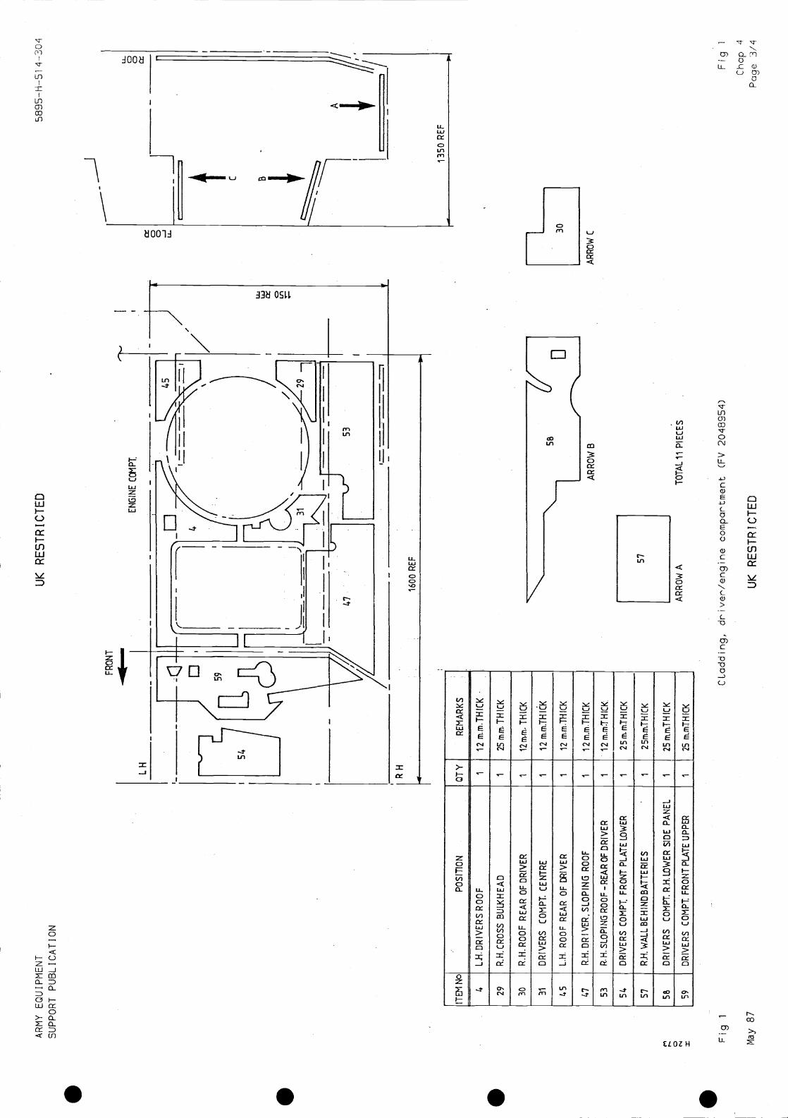
driver/engine compartment (FV 2048954) ...cross bulkhead (FV 2048955) ... ... ..left hand side (FV 2048956) ... ... ..right hand side (FV 2048957) .. ...rear wall and door (FV 2048958) ... ...roof, internal (FV 2048959) .. .
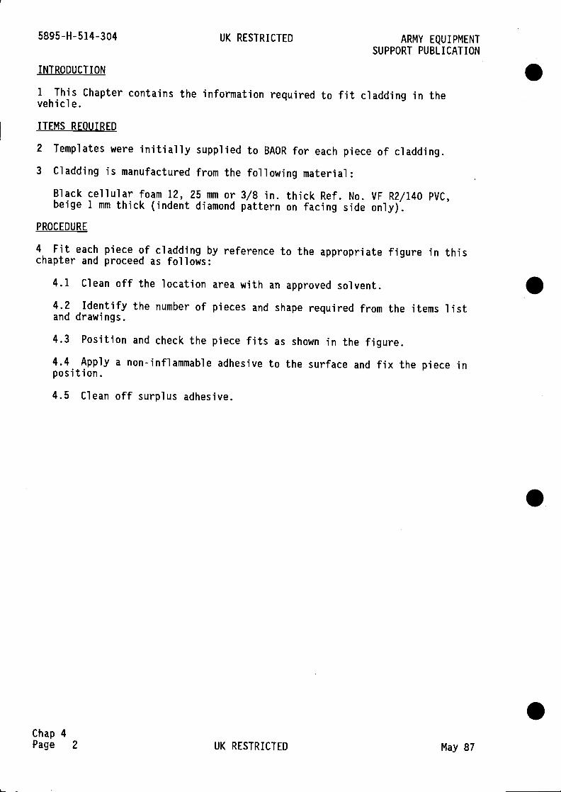
INTRODUCTION
1 This Chapter contains the information required to fit cladding in thevehicle.
ITEMS REQUIRED
2 Templates were initially supplied to BAOR for each piece of cladding.
3 Cladding is manufactured from the following material:
Black cellular foam 12, 25 mm or 3/8 in. thick Ref. No. VF R2/140 PVC,beige 1 mm thick (indent diamond pattern on facing side only).
PROCEDURE
4 Fit each piece of cladding by reference to the appropriate figure in thischapter and proceed as follows:
4.1 Clean off the location area with an approved solvent.
4.2 Identify the number of pieces and shape required from the items listand drawings.
4.3 Position and check the piece fits as shown in the figure.
4.4 Apply a non-inflammable adhesive to the surface and fix the piece inposition.
4.5 Clean off surplus adhesive.
5895-H-514-304 UK RESTRICTED ARMY EQUIPMENTSUPPORT PUBLICATION
S
S
SChap 4Page 2 UK RESTRICTED May 87
AR
MY
EQ
UIP
ME
NT
SU
PP
OR
T P
UB
LIC
AT
ION
UK
RE
ST
RIC
TE
D
C C -J U-
5895
—H
--S
i
FR
ON
T
U- 0
*
4,
ITE
M N
oP
OS
ITIO
NO
TY
RE
MA
RK
S
6L.
H.D
RIV
ER
S R
OO
F1
12 m
.m.T
HIC
K
29R
.H.C
RO
SS
BU
U<
HE
AD
125
m.m
.TH
ICK
30R
.H.R
OO
F R
EA
R O
F D
RIV
ER
112
mm
. TH
ICK
31D
RIV
ER
S C
OM
PT
. CE
NT
RE
112
m.m
.TH
ICK
45L.
H. R
OO
F R
EA
R O
F D
RIV
ER
112
mm
.TH
ICK
47R
H. D
RIV
ER
. SLO
PIN
G R
OO
F1
l2rn
.m.T
HT
CK
53R
. H. S
LOP
ING
RO
OF
-R
EA
R O
F D
RIV
ER
112
m.m
.'TH
ICK
.
54D
RIV
ER
S C
OM
PT
. FR
ON
T P
LAT
E L
OW
ER
125
m.m
TH
ICK
57R
.H.W
ALL
BE
HIN
DB
AT
TE
RIE
S1
25m
.m.T
HIC
K
SB
DR
IVE
RS
CO
MP
T. R
H. L
OW
ER
SID
E P
AN
EL
125
m.m
.TH
ICK
59D
RIV
ER
S C
OM
PI F
RO
NT
PLA
TE
UP
PE
R1
25
1350
RE
F
0 x
AR
RO
W B
AR
RO
W C
AR
RO
W A
1C
Ladd
ing,
driv
er/e
ngin
ecompartment (FV 2048954)
May
87
UK
RE
ST
RIC
TE
D
TO
TA
L 11
PIE
CE
S
Fig
1
Cha
p.4
Pag
e

. . . .

AR
MY
EQ
UIP
ME
NT
SU
PP
OR
T P
UB
LIC
AT
ION
UK
RE
ST
RIC
TE
D58
95—
H-5
1 4-
304
U-. U,
rT,
TO
TA
L 10
PIE
CE
S
Fig
2C
Ladd
ing,
cro
ss b
uLkh
ead
(FV
204
8955
)
May
87
UK
RE
ST
RIC
TE
D
Fig
2C
hap
4P
age
5/b
L.H
.
37
ITE
MN
°P
OS
ITIO
NO
TY
RE
MA
RK
S
18C
RO
SS
BU
LXH
EA
D -
LOW
ER
RIG
HT
125
m.n
tTH
ICK
23C
RO
SS
BU
LKH
EA
D-R
.H.S
LOP
ING
FA
CE
125
m.r
n.T
HIC
K
36C
RO
SS
BU
LKH
EA
D C
OV
ER
PLA
TE
R.H
.1
12m
m. T
HIC
K
37C
RO
SS
BU
LKH
EA
D-S
LOP
ING
FA
CE
CE
NT
RE
125
m.m
.TH
ICK
38C
RO
SS
BU
U(H
EA
D-D
RIV
ER
SC
OM
PT
FR
ON
T1
25m
mT
HIC
K
39C
RO
SS
BU
LKH
EA
D -
L.H
.SLO
PIN
G F
AC
E1
25m
.mT
HIC
K
41C
RO
SS
BU
U<
HE
AD
-CO
VE
R P
LAT
E C
EN
TR
E1
12m
.m.T
HIC
K
63C
RO
SS
BU
LKH
EA
D -
CO
VE
R P
LAT
E -
NE
AR
SID
E1
12m
.m.T
HIC
K
46C
RO
SS
BU
LKH
EA
D -
LOW
ER
LE
FT
1l2
mnm
TH
ICK
62C
RO
SS
BU
LXH
EA
D L
H.F
RO
NT
1l2
mn.
mnT
HIC
K
IN D
RIV
ER
S C
OM
PA
RT
ME
NT
38]
1
R.H
.
RO
OF
0 N
1400
RE
F

S S S S
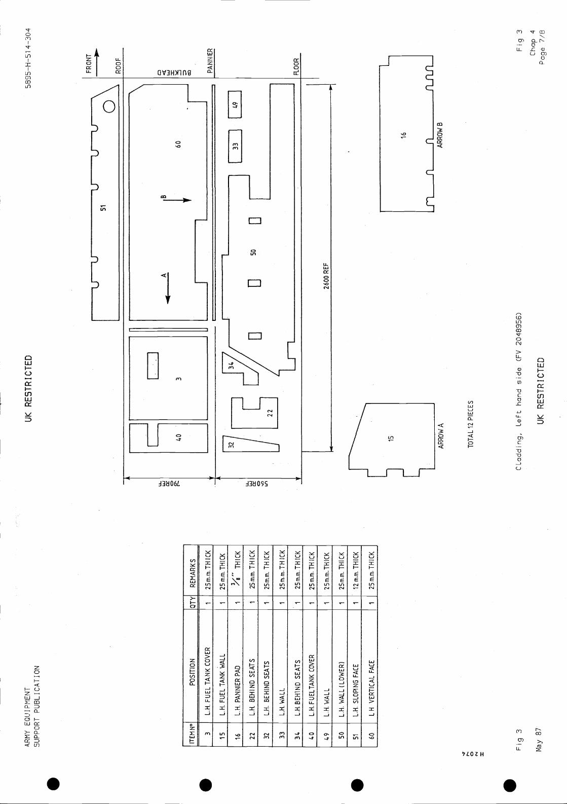
0 =
AR
MY
EQ
UIP
ME
NT
SU
PP
OR
T P
UB
LIC
AT
ION
w tx
UK
RE
ST
RIC
TE
D58
95—
H—
Si 4
—30
4
D -J PA
NN
IER
Fig
3C
Ladd
ing,
Left
hand
sid
e (F
V 2
0489
56)
May
87
UK
RE
ST
RIC
TE
D
Fig
3C
hap
4P
age
7/8
if51
UU
U
0F
RO
NT
RO
O F
ITE
MN
°P
OS
ITIO
NO
TY
RE
MA
RK
S
3L.
H.F
UE
LTA
NK
CO
VE
R1
25m
.m.T
HIC
K
15L.
H.F
UE
LTA
NK
WA
LL1
2Srn
.m.T
HIC
K
16L.
H. P
AN
NIE
R P
AD
1T
HIC
K
22L.
H. B
EH
IND
SE
AT
S1
25m
.m.T
HIC
K
32L.
H. B
EH
IND
SE
AT
S1
25m
m. T
HIC
K
33L.
H.W
ALL
125
m.m
.TH
ICK
34L.
H.B
EH
1ND
SE
AT
S1
25m
.rn.
TH
ICK
40L.
H.F
UE
LTA
NK
CO
VE
R1
25m
.m.T
HIC
K
49L.
H. W
ALL
125
mm
.TH
ICK
50L.
H. W
ALL
(LO
WE
R)
125
mm
. TH
ICK
51L.
H. S
LOP
ING
FA
CE
112
m,r
n. T
HIC
K
60L
H V
ER
TIC
AL
FA
CE
125
mm
. TH
ICK
w IJ,
7
1[
491
2600
RE
F
RO
OR
AR
RO
W A
TO
TA
L 12
PIE
CE
S
AR
RO
W B

. . . .
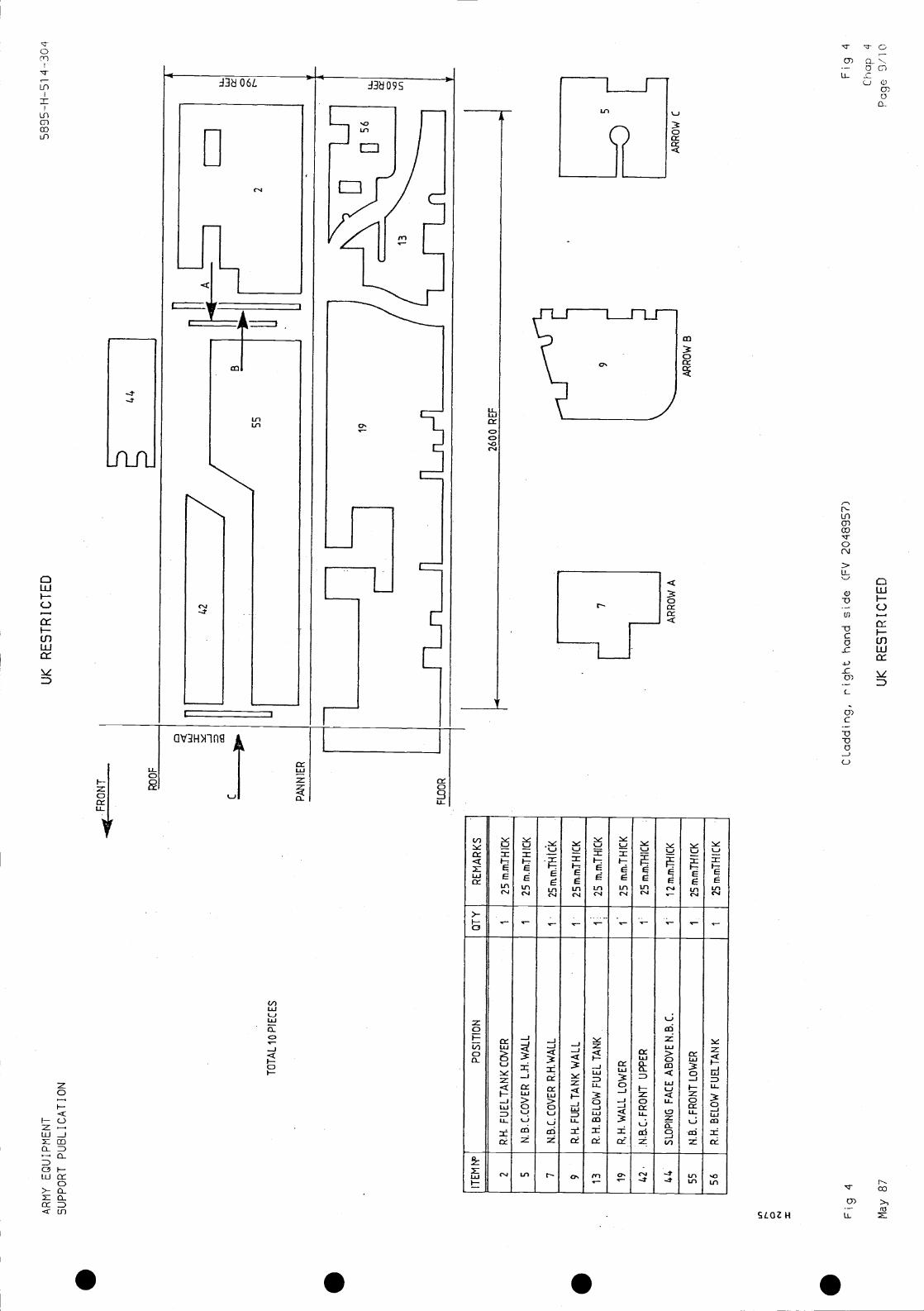
AR
MY
EQ
UIP
ME
NT
SU
PP
OR
T P
UB
LIC
AT
ION
0
UK
RE
ST
RIC
TE
D58
95—
H—
Si 4
—30
4
Fig
4C
Ladd
ing,
rig
ht h
and
side
(F
V 2
0489
57)
May
87
UK
RE
ST
RIC
TE
D
TO
TA
L 10
PIE
CE
S
PO
SIT
ION
OT
YR
EM
AR
KS
2R
H. F
UE
LTA
NK
125
m.m
TH
ICK
5N
B. C
.CO
VE
R L
.H.W
ALL
125
m.m
.TH
ICK
7N
.B.C
. CO
VE
R R
.H.W
ALL
125
ntrn
.TH
tCK
9R
H. F
UE
L T
AN
K W
ALL
t25
m.m
TH
ICK
13R
.H.B
ELO
W F
UE
L T
AN
K1
25 In
.m.T
HIC
K
19P
. H. W
ALL
LO
WE
R1
25 r
Tun
.TH
ICK
62N
.B.C
. FR
ON
T U
PP
ER
125
m.m
.TH
ICK
I
44S
LOP
ING
FA
CE
AB
OV
E N
.B.C
.I
12m
.m.T
HIC
K
55N
B. C
. FR
ON
T L
OW
ER
I
56R
H. B
ELO
W F
UE
LTA
NK
125
m.m
TH
ICK
AR
RO
W A
AR
RO
W B
AR
RO
W C
Fig
4C
hap
4P
age
9/10

. . . .
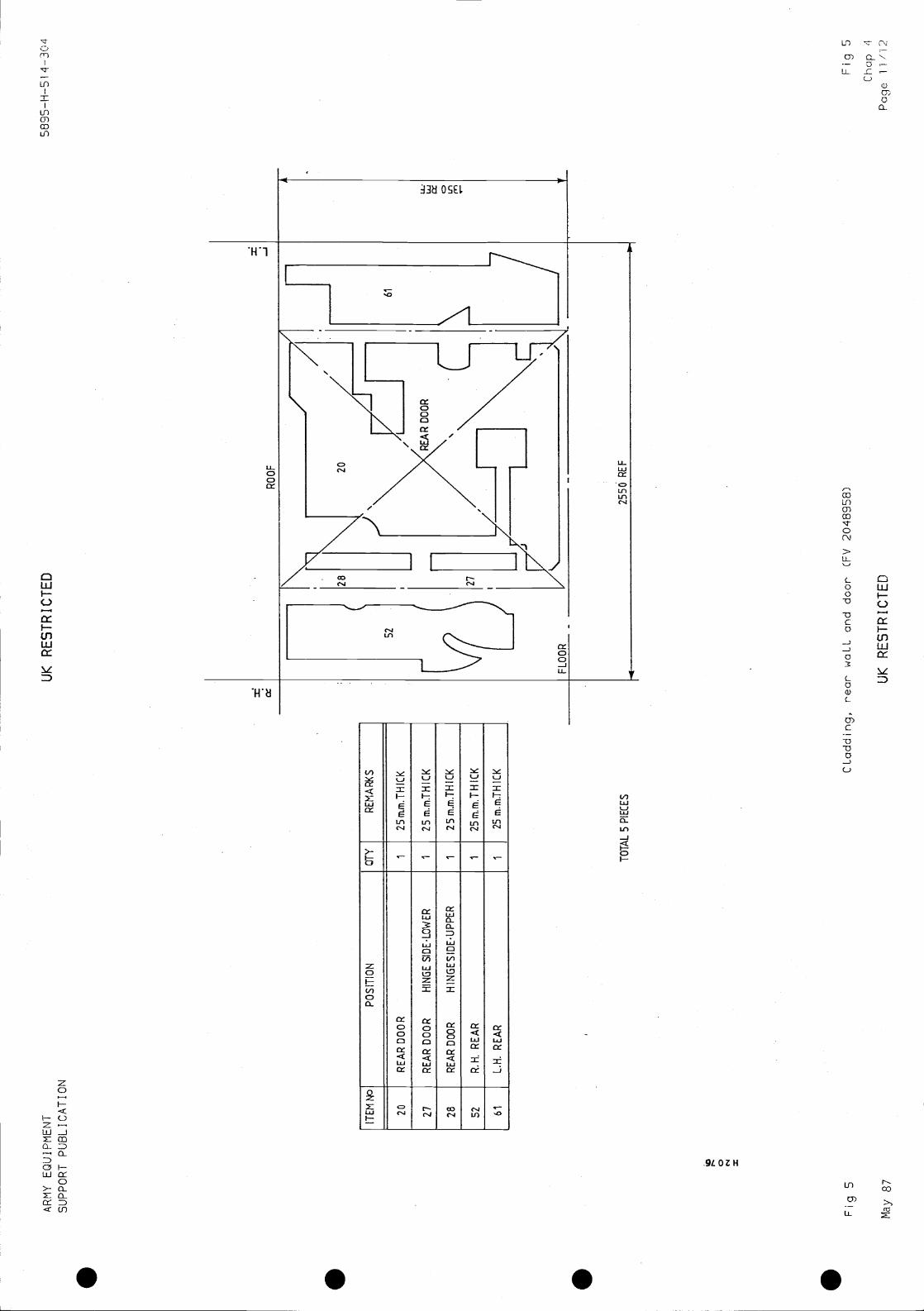
AR
MY
EQ
UIP
ME
NT
SU
PP
OR
T P
UB
LIC
AT
ION
UK
RE
ST
RIC
TE
D58
95—
H—
Si 4
—30
4
ITE
M N
oP
OS
ITIO
NO
TY
RE
MA
RI<
S
20R
EA
R D
OO
R1
25m
.m.T
HIC
K
Z7
RE
AR
DO
OR
HIN
GE
SID
ELO
WE
R1
25m
.m.T
HIC
K
28R
EA
R00
0RH
ING
ES
IDE
UP
PE
R1
25m
.m.T
HIC
K
52R
.H. R
EA
R1
25m
.m.T
HIC
K
61L.
H. R
EA
R1
25 r
n.rn
.TH
ICK
0 N z
TO
TA
L 5
PIE
CE
S
Fig
5C
Ladd
ing,
rea
r w
aLL
and
door
(F
V 2
0489
58)
May
87
UK
RE
ST
RIC
TE
D
Fig
5C
hap
'1
Pag
e 11
/12

. . . .

AR
MY
EQ
UIP
ME
NT
SU
PP
OR
T P
UB
LIC
AT
ION
FR
ON
T
UK
RE
ST
RIC
TE
D58
95—
H—
51 4
—30
4
ITE
M N
oP
OS
ITIO
NO
TY
RE
MA
RK
S
1R
OO
F F
RO
NT
Lii.
112
m.m
.TH
ICK
6R
.H.R
OO
FF
UE
L P
IPE
S1 I
12 m
.mT
hIC
K
8R
.H. R
OO
F C
EN
TR
E,R
EA
R.
12m
.mT
HIC
K
10R
.H.R
OO
F B
EH
IND
FU
ELP
IPE
S1
l2rt
uitT
HIC
K
111
12m
.m.T
HIO
<.
12L.
H. R
OO
F F
RO
NT
FU
ELP
IPE
S1
12m
.m.T
HIC
K
14R
.H. R
OO
F C
EN
TR
E1
12 r
n.m
.TH
ICK
17Li
i. R
OO
F C
EN
TR
E1
12 m
,mT
HIC
I<
21L.
H. R
OO
F B
EH
IND
FU
EL
PIP
ES
112
m.m
.TH
ICK
25R
.H.R
OO
FC
EN
TR
E F
RO
NT
I12
m.m
TH
ICK
26L.
H.R
OO
FC
EN
TR
ER
EA
RI 1
12m
,m.T
HIC
I<
N 0 N
TO
TA
L 12
PIE
CE
S
Fig
6
Nay
87
CLa
ddin
g, r
oof,
inte
rnaL
(F
V 2
0489
59)
EN
D
UK
RE
ST
RIC
TE
D
Fig
6C
hap
413
/)4

. . . .
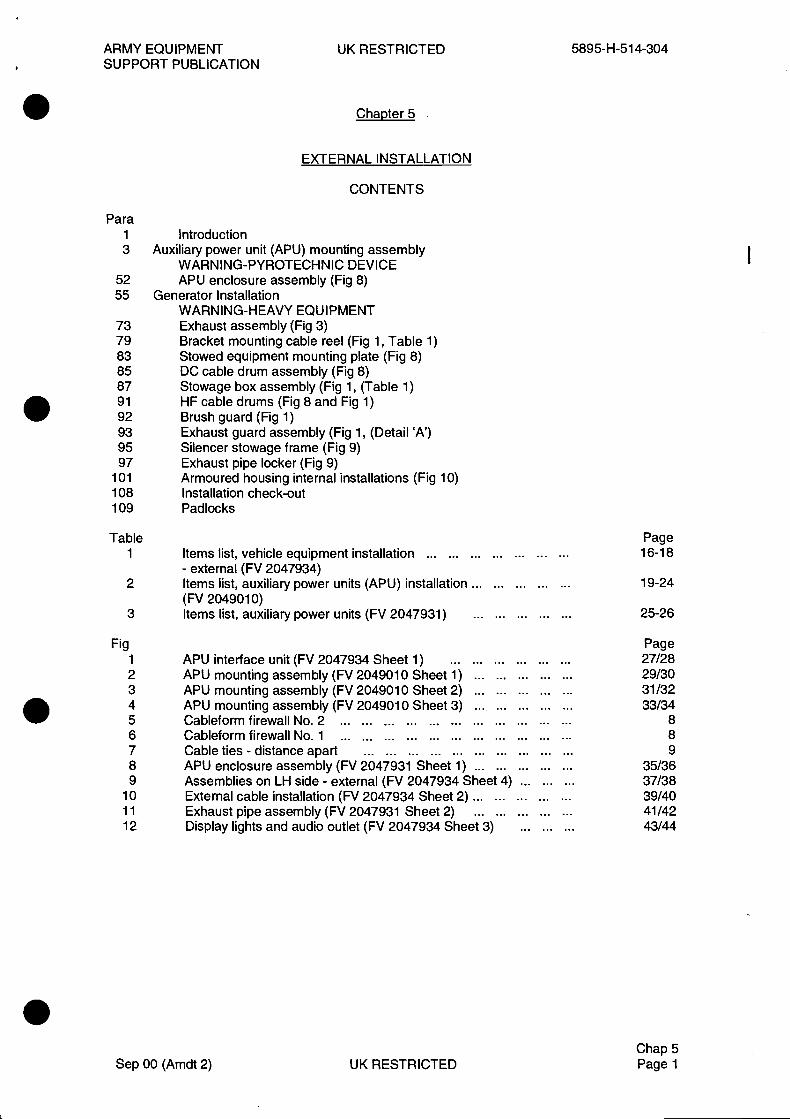
ARMY EQUIPMENT UK RESTRICTED 5895-H-514-304SUPPORT PUBLICATION
Chapter 5
EXTERNAL INSTALLATION
CONTENTS
Para1 Introduction3 Auxiliary power unit (APU) mounting assembly
WARNING-PYROTECHNIC DEVICE52 APU enclosure assembly (Fig 8)55 Generator Installation
WARNING-HEAVY EQUIPMENT73 Exhaust assembly (Fig 3)79 Bracket mounting cable reel (Fig 1, Table 1)83 Stowed equipment mounting plate (Fig 8)85 DC cable drum assembly (Fig 8)87 Stowage box assembly (Fig 1, (Table 1)91 HF cable drums (Fig 8 and Fig 1)92 Brush guard (Fig 1)93 Exhaust guard assembly (Fig 1, (Detail 'A')95 Silencer stowage frame (Fig 9)97 Exhaust pipe locker (Fig 9)
101 Armoured housing internal installations (Fig 10)108 Installation check-out109 Padlocks
Table Page1 Items list, vehicle equipment installation 16-18
- external (FV 2047934)2 Items list, auxiliary power units (APU) installation ... 19-24
(FV 2049010)3 Items list, auxiliary power units (FV 2047931) 25-26
Fig Page1 APU interface unit (FV 2047934 Sheet 1) 27/282 APU mounting assembly (FV 2049010 Sheet 1) 29/303 APU mounting assembly (FV 2049010 Sheet 2) 31/324 APU mounting assembly (FV 2049010 Sheet 3) 33/345 Cableform firewall No. 2 86 Cableform firewall No. 1 87 Cable ties - distance apart 98 APU enclosure assembly (FV 2047931 Sheet 1) 35/369 Assemblies on LH side - external (FV 2047934 Sheet 4) 37/38
10 External cable installation (FV 2047934 Sheet 2) 39/4011 Exhaust pipe assembly (FV 2047931 Sheet 2) 41/4212 Display lights and audio outlet (FV 2047934 Sheet 3) 43/44
Chap 5Sep 00 (Amdt 2) UK RESTRICTED Page 1
5895-H-514-304 UK RESTRICTED ARMY EQUIPMENTSUPPORT PUBLICATION
INTRODUCTION
This chapter provides installation instructions for items mounted externally.
2 For ease of reference during installation all item numbers are directly related to thedefinitive drawings produced by the development contractor. Tables 1, 2 and 3 relate to thosedrawings and figures in this folder.
Note
Before commencing, clean out all threads in bosses and plates.
AUXILIARY POWER UNIT (APU) MOUNTING ASSEMBLY
3 Assemble and fit the APU Mounting Assembly in the following sequence:
3.1 Fit and secure gasket (Table 1 item 32) and APU Interface Unit (21) to roof atposition shown in Fig 1 using ten M8 x 25 screws (75),plain washers (79) and lockwashers (80).
3.2 Fit and secure the following items shown in Fig 2 (Table 2):
3.2.1 Mounting Angle (12) in two positions on APU skirt using two M8 x 30screws (153), four flat washers (177), two lock washers (178) and two full nuts(62) at each position.
3.2.2 Guide Rail (13) on skirt in four positions using three M8 x 30 screws(153), six flat washers (177), three lock washers (178) and three nuts (201) ateach position.
3.2.3 Two Clamp Blocks (14) on skirt in four positions as shown in Figs 2and 4 using two M6 x 25 screws (147), two flat washers (172), two lockwashers (173) in one clamp block and two M6 x 25 screws (147), one flatwasher (172), two lock washers (173), one flat washer (174) and lanyardassembly (106) at the second clamp block for each position.
3.2.4 Baffle plate (5) (Firewall No. 2) and tray (26) to APU No. 2 positionusing three M8 x 30 screws (153), six flat washers (177), three lock washers(178) and three M8 nuts (201).
3.2.5 Baffle plate (6) (Firewall No. 1) and tray (27) using fixings as for Item 5paragraph 3.2.4.
3.2.6 Two plate adaptors (28) one on to the rear face of firewall No. 2 (5) andthe other on to Firewall No. 1 (6) using four M6 x 20 screws (146), eight flatwashers (172), four lock washers (173) and four M6 full nuts (199) in twopositions.
Notes
(1) Position each plate adaptor with the flat part at the top.
(2) Do not remove the top fixing screw.
.Chap 5Page 2 UK RESTRICTED Oct 94 (Amdt 1)

ARMY EQUIPMENT UK RESTRICTED 5895-H-514-304SUPPORT PUBLICATION
(3) From now on, the baffle plates are referred to as FirewallHo. 1 and Firewall No. 2 in accordance with markings on each
firewall.
3.2.7 Fit RH mounting bracket (24) on Firewall No. 2 using twoM6 x 20 screws (146), four flat washers (172), two lock washers(173) and two M6 full nuts (199).
3.2.8 Fit LH mounting bracket (25) on Firewall No. 1 usingfixings as for Item 24.
3.2.9 Fit protective cap (129) to APU Interface unit.
4 Refer to Figs 2 and 3 to fit the following items (Table 2) on FirewallsNo. 1 and No. 2:
4.1 Assemble and fit quick release coupling (115), '0' ring (117),Adaptor BSP/BSP (111), to bracket 24 on Firewall No. 1 and secure withlocking nut (113) (Detail 'W' Fig 3).
4.2 Repeat Para 4.1 for bracket 25 on Firewall No. 2.
4.3 Three HD sockets (94) on outer face of Firewall No. 1 and threeHO sockets (94) on outer face of Firewall No. 2 at positions marked SKi,SK2, SK3. (See Fig 3 Sect E-E).
4.4 Two HD plugs (96) at position marked PL1 on Firewall No. 1 andFirewall No. 2 (See Fig 3 Sect F-F).
4.5 Bulkhead adaptor (32) on Firewall No. 1 and No. 2 as shown in Fig4 (Detail 'C' Fig 2 and 4).
4.6 Bulkhead adaptor 90° (108) on Firewall No. 1 and No. 2 as shownin Fig 4 (Detail 'A' Fig 2 and 4).
4.7 Fit one Plate Adaptor (19) to cable (85) as shown in Fig 2 usingfour M3 x 12 screws (133), eight flat washers (160). four lock washers(161), four nuts (194) and fit and secure on Firewall No. 2 using four M6x 20 screws (146), eight flat washers (172), four lock washers (173) andfour M6 full nuts (199).
4.8 Fit other Plate Adaptor (19) to cable (84) and fit and secure onFirewall No. 1 using fixings as for paragraph 4.7.
4.9 Refer to Fig 2 and fit and secure the two fire bottle mountingbrackets (102) on mounting bracket (16) using two M8 x 60 bolts (155),four flat washers (177), two lock washers (178) and two M8 full nuts(201).
5 Fit and secure the assembled mounting bracket (16) on the angle betweenFirewalls No. 1 and No. 2 as shown in Fig 2 using four M6 x 20 screws (146),eight flat washers (172), four lock washers (173) and four M6 full nuts(199).
6 Fit and secure mounting frame (17) between Firewalls No. 1 and No. 2 atposition shown in Fig 2 using four M6 x 25 screws (147), eight flat washers(172), four lock washers (173) and four M6 full nuts (199).
Chap 5Oct 94 (Amdt 1) UK RESTRICTED Page 3
5895-H-514- 304 UK RESTRICTED ARMY EQUIPMENTSUPPORT PUBLICATION
Chap 5Page 4 UK RESTRICTED Oct 94 (Amdt 1)
.
7 Fit and secure the Fire Warning Junction box (23) on the mounting frame(17) using one M8 x 20 screw (151) fitted with one flat washer (177) and onelock washer (178) in one position, and one M8 x 20 screw (151) and twoshakeproof washers (179) with earth tag from back of box between, followed bythe flat washer (177) supplied with box. (See Fig 4 Sect Z-Z).
8 Fit and secure the bracket assembly (22) on the mounting frame (17) usingtwo M8 x 20 screws (151), fitted with two flat washers (177) and two lockwashers (178) (See Fig 4 Sect Z-Z).
9 Fit andfilter (33)
secure two plugs (45) fitted with two sealing washers (44) to thein the positions shown in Fig 4.
10 Fit and secure two adaptors (43) fitted with two sealing washers (44) tothe filter (33) in the positions shown in Fig 4.
11 Fit and secure filter (33) on the bracket (22) using two flat washers(182), two lock washers(183) and two M1O nuts (203).
12 Fit the following cable assemblies to the following connectors on innerface of Firewall No. 1 using shakeproof washers (190) (see Fig 2).
ItemItemItem
656778
FV2O50218/8FV2050218/10FV2050356/1
(HHI/Mv(HHI/Mv(HHI/Mv
1015/12)1015/14).1154/1)
tototo
5K2SK3PL1
CableCableCable
No.No.No.
185187181
Item 63 FV2050218/6 (HHIIMV 1015/10) to SKi Cable No. 183
S
S
S
13 Fit the following cable assemblies to the following connectors on innerface of Firewall No. 2 using shakeproof washers (190) : (see Fig 2).
Item 66Item 68Item 79Item 64
FV2050218/9FV2050218/1 1FV2050356/2FV2050218/7
(HHI/Mv 1015/13)(HHI/Mv 1015/15(HHI/Mv 1154/2)(HHI/Mv 1015/11)
to SK2to SK3to PLIto SKI
14 Connect the following cable assemblies shown in Fig 2Interface Unit:
Cable No.Cable No.Cable No.Cable No.
to the APU
186188182184
FV2050359/1FV2050218/6
(HHI/Mv(HHI/MV
1157/1)1050/10)
(84)(63)
toto
PL9SK5
FV2050356/1 (HHI/MV 1154/1) (78) to PL7FV2050218/10 (HHI/MV 1015/14) (67) to SK7FV2050218/8 (HHI/MV 1015/12) (65) to SK9FV2050218/9 (HHI/Mv 1015/13) (66) to SK1OFV2050218/11 (HHI/Mv 1015/15 (68) to SK8FV2050356/2 (HIll/MVFV2050218/7 (HHIIMvFV2050359/2 (HHI/Mv
1154/2)1015/11)1157/2)
(79)(64)(85)
tototo
PL8SK6PL1O
15 Fit Keep strip (31) (2 off), on weather strip (30) (2inner faces of Firewall No. 1 and No. 2 using six M4 x 25twelve flat washers (164), six lock washers (165) and sixas shown in Fig 2.
16 Fit andConnect fuelFirewall No.
off) and secure toscrews (137),M4 full nuts (196)
secure '1' piece (41) to bulkhead adaptor (32) on Firewall No.hose (34) between piece (41) and bulkhead adaptor (32) onI (see Fig 4 Detail 'C').
2.
ARMY EQUIPMENT UK RESTRICTED 5895-H-514-304SUPPORT PUBLICATION
17 Fit and secure fuel hose (35) between 'T' piece (41) and roof interface plate (see Figs 2and 4).
18 Fit and secure 'T' piece (42) to bulkhead adaptor (108) on Firewall No. 1. Connect fuelhose (40) between 'T' piece (42) and bulkhead adaptor (108) on firewall No. 2 (see Fig 4 DetailA).
19 Fit and secure fuel hose (39) between 'T' piece (42) and adaptor (43) on filter (33). (seeFig 4 view on arrow 'T').
20 Fit and secure fuel hose (38) between adaptor (43) on filter (33) and the roof interfaceplate (see Figs 2 and 4).
21 Prior to fitting two detectors (46) on inner faces of Firewalls No. 1 and No. 2 (Fig 2)connect cable (87) to one detector and cable (88) to the other as follows:
Note
On cables 87 and 88 there are two pairs of white wires, each paircarry an ident sleeve marked with letter A on one wire and Bon the other.
Procedure
21.1 On cable 87 strip back each wire approximately 4 mm.
21.2 On each pair of wires fit gland nut (123) and ferrule (125), domed end intogland nut.
21.3 Crimp 3 mm eye tag (127) on each of the four wires.
21.4 Prise off cover plate from detector. Remove and retain the two terminalscrews and washers.
21.5 Feed both wires of one pair through into the terminal block on one side of thedetector and the second pair through into the terminal block on the other side of thedetector.
21.6 Secure the wires to the terminal block using the screws and washers retainedat para 21.4, ensure wires idented A connect to terminal A and wires idented B connectto terminal B (Fig 4 refers).
21.7 Fit gland nuts on casing and secure.
21.8 Fit cover plate on detector.
21.9 Repeat paras 21.1 to 21.8 for cable 88.
21.10 With cables (87) and (88) connected to the two detectors, fit the detector withcable (87) on inner face of Firewall No. 2 as indicated in Fig 2, using two M4 x 45 screws(139), four flat washers (164), two lock washers (165) and two nuts (196).
21.11 Fit the other detector with cable (88) on Firewall No. 1
22 Connect cables (87) and (88) to the Fire Warning Junction Box (23) as shown in Fig 4.Connect the other end of cables (87) and (88) to adaptor plate (28) on Firewalls No. 1 and No. 2
Chap 5Oct 94 (Amdt 1) UK RESTRICTED Page 5
5895-H-514-304 UK RESTRICTED ARMY EQUIPMENTSUPPORT PUBLICATION
WARNING-PYROTECHNIC DEVICE
THE APU FIRE EXTINGUISHER INITIATOR CARTRIDGES CONTAIN GUNPOWDER.ALWAYS HANDLE WITH CARE.
23 To fit the APU tire extinguisher proceed as follows.
Note...
To comply with CFC emissions regulations, Halon 1211 (BCE) gas is used. There arenow two variants of bottles, which are of slightly larger diameter. To accommodate thevariation in bottle diameter, the cork strip, bonded to the mounting bracket retainingstraps is to be removed and replaced with rubber strip. Refer to Modification InstructionNo. TBA
23.1 Before installation ensure that the last weight check was within the precedingthree months.
23.2 Remove the transit cap from the initiator cartridge mounting port and fit theinitiator cartridge unit (104) onto its mounting studs using the tab washers and four nutstightened to a torque of 1.5 Nm. Remove the transit cap from the discharge outlet and fitthe anti-recoil cap.
23.3 With the head downwards, secure the extinguishers (100) into the mountingbrackets. Do not connect the electrical cables at this stage.
24 Remove the anti-recoil cap. Lightly grease the threads on each fire extinguisher usinggrease extreme pressure (121) and secure the extinguisher discharge pipes (48) to each outlet.
25 Fit the electrical cables (75) and (76) to the two firing units (104). Connect the other endof the cables to the Fire Warning Junction Box (23) as shown in Fig 4.
26 Fit pipe assembly (48) on each fire extinguisher (100), (2 off).
27 Put cables (87) and (75) together and clip to Firewall No. 2 in seven positions using 'P'clips (92) secured with M5 x 10 screws (142), fIat washer (168) and lock washer (169) as shownin Fig 2.
28 Put cables (88) and (76) together and clip to Firewall No. 1 in seven positions using 'P'clips (92) secured as in Para 27.
29 Connect cable (70) to the Fire Warning Junction Box (23) as shown in Fig 4. Connectother end of cable to APU Interface SKi 1.
30 Prior to fitting four detectors (46) on outer faces of Firewalls No. 1 and No. 2 (Fig 3),connect cable (81) to two detectors and cable (82) to the other two detectors as follows:
Note
On cables 81 and 82 there are four pairs of white wires each pair carries anindent sleeve marked with letter A on one wire and B on the other.
30.1 On cable 81 strip back each wire approximately 4 mm.
30.2 On each pair of wires, for one detector, fit gland nut (123) and ferrule (125),domed end into gland nut.
30.3 Crimp a 3 mm eye tag (127) on each of the four wires.
30.4 Prise off the cover plate from the detector. Remove and retain the two terminalscrews and washers.
30.5 Feed both wires of one pair through into the terminal block on one side of thedetector and the second pair through into the terminal block on the other side of thedetector.
Chap 5Page 6 UK RESTRICTED Sep 00 (Amdt 2)
ARMY EQUIPMENTSUPPORT PUBLICATION
30.6 Secure the wires to the terminal block using the screws and washers removedat para 30.4, ensure wires idented A connect to terminal A and wires idented B connect toterminal B (Fig 4 refers).
30.7 Fit gland nuts to detector casing and secure.
30.8 Fit cover plate on the detector.
30.9 Repeat paras 30.2 to 30.8 for the second detector.
30.10 Repeat paras 30.1 to 30.9 for cable (82).
31 Fit and secure detectors attached to cable (81) on the outer face of Firewall No. 2 asshown in Fig 3, using two M4 x 45 screws (139), four flat washers (164), two lock washers(165), two M4 nuts (196) at each detector.
32 Connect cable (81) to adaptor plate SK4 (Fig 3).
33 Align cable (81) to the firewall and ensure in position using cable clip (92), M5 x 10 screw(142), flat washer (168), lock washer (169) in three positions (Fig 3).
34 Repeat paras 31 to 33 to secure detectors and cable (82) to the outer face of FirewallNo.1.
35 Fit the following items on Firewall No. 1 outer face (see Figs 3 and 4).
35.1 Fuel line assembly (51) between bulkhead adaptor (108) and coupling onbracket (24).
35.2 Fuel line assembly (50) to the quick-release coupling on bracket (24).
35.3 Hose (53) to the bulkhead adaptor (32).
35.4 Cable Assembly FV2050208/5 (HHI/MV 1005/17A) (55) to PL1.
35.5 Cable Assembly FV205020817 (HHI/MV 1005/1 9A) (57) to SK3.
35.6 Cable Assembly FV205021 8/2 (HHI/MV 101 5/6A) (59) to Ski.
35.7 Cable Assembly FV2050218/4 (HHI/MV 1005/8A) (61) to SK2.
35.8 Cable Assembly FV2050269/1 (HHI/MV 1 067/3C) (72) to PL2.
36 Align the fuel pipes (53 and 50) and secure with cable ties (119) tocable (82) (see Fig 3).
37 Fit and secure clamp assembly (8) for the cables and cable clip (93) for the fuel linesusing two M6 x 35 screws (148), four flat washers (172), two tock washers (173) and two full M6nuts (199) (see Fig 3).
38 Fit the following items on Firewall No. 2 outer face (see Figs 3 and 4):
38.1 Fuel line assembly (51) between bulkhead adaptor (108) and coupling onbracket (25).
38.2 Fuel line assembly (49) to the quick release coupling on bracket (24).
38.3 Hose (52) to the bulkhead adaptor (32).
38.4 Cable Assembly (FV2050269/2) (HHI/MV 1067/4C) (73) to PL2.
38.5 Cable Assembly (FV2050208/4) (HHI/MV 1005/i 6A) (54) to PL1.
38.6 Cable Assembly (FV2050208/6) (HHI/MV 1005/18) (56) to SK3.
38.7 Cable Assembly (FV2050218/3) (HHI/MV 101 517B) (60) to SK2.
Chap 5Sep 00 (Amdt 2) UK RESTRICTED Page 7
UK RESTRICTED 5895-H-51 4-304

5895-H-51 4-304 UK RESTRICTED ARMY EQUIPMENTSUPPORT PUBLICATION
38.8 Cable Assembly (FV2050218/5) (HHI/MV 1005/9B) (62) to Ski.
39 Align the fuel pipes (52 and 49) and secure with cable ties (119) tocable (81) (see Fig 3).
40 Fit and secure clamp assembly (8), for the cables and fuel line (49) andcable clip (91)for fuel hose (52) using two M6 x 35 screws (148), four flatwashers (172), two lock washers (173) and two full M6 nuts (199) (see Fig 3).
41 With the cables connected on both Firewalls, form cables into a loom asshown in Fig 5 and 6:
5 Cableform Firewall No. 2 Fig 6 Cableform Firewall No. 1
Chap 5Page 8 UK RESTRICTED Oct 94 (Amdt 1)
.
.
PL2
P Li
SK2
SKi
SK3
.Ski PL1
Sk2
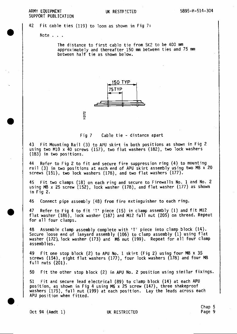
ARMY EQUIPMENT UK RESTP!CTED 5895-H-514-304SUPPORT PUBLICATION
42 Fit cable ties (119) to loom as shown in Fig 7:
Note
The distance to first cable tie from SK2 to be 400 mmapproximately and thereafter 150 mm between ties and 75 mmbetween half tie as shown below.
TYP
7STYP
I.-
=
Fig 7 Cable tie - distance apart
43 Fit Mounting Rail (3) to APU skirt in both positions as shown in Fig 2using two M10 x 40 screws (157), two flat washers (182), two lock washers(183) in two positions.
44 Refer to Fig 2 to fit and secure fire suppression ring (4) to mountingrail (3) in two positions at each end of APU skirt assembly using two M8 x 20screws (151), two lock washers (178), and two flat washers (177).
45 Fit two clamps (18) on each ring and secure to Firewalls No. 1 and No. 2using M8 x 25 screw (152), lock washer (178), and flat washer (177) as shownin Fig 2.
46 Connect pipe assembly (48) from fire extinguisher to each ring.
47 Refer to Fig 4 to fit piece (15) in clamp assembly (1) and fit M12flat washer (186), lock washer (187) and M12 full nut (205) on thread. Repeatfor all four clamps.
48 Assemble clamp assembly complete with '1' piece into clamp block (14).Secure loose end of lanyard assembly (106) to clamp assembly (1) using flatwasher (172), lock washer (173) and M6 nut (199). Repeat for all four clampassemblies.
49 Fit one stop block (2) to APU No. 1 skirt (Fig 2) using four 148 x 35screws (154), eight flat washers (177), four lock washers (178) and four M8full nuts (201).
50 Fit the other stop block (2) in APU No. 2 position using similar fixings.
51 Fit and secure lead electrical (89) to clamp block (14) at each APUposition, as shown in Fig 4 using M6 x 25 screw (147), three shakeproofwashers (175), full nut (199) at each position. Lay the leads across eachAPU position when fitted.
Chap 5Oct 94 (Amdt 1) UK RESTRICTED Page 9
5895-H-514-3O4 UK RESTRICTED ARMY EQUIPMENTSUPPORT PUBLICATION
APU ENCLOSURE ASSEMBLY (Fig 8, Table 3)
52 Hoist/lift the APU Enclosure Assembly (7) on to the roof.
CAUTION
Before hoisting into position check each APU position to ensure allcables, fuel lines and fittings are inside the APU area. Use cable tiesto hold cables clear.
53 Open, and secure with clasps, the three doors on top of the enclosure andthe two APU entry doors. This will enable the installers to visually locatethe enclosure assembly with the APU installation.
54 Secure in position as indicated in Fig 8 using shims (16) and (17) andfourteen M16 x 50 screws (42), fourteen flat washers (19), fourteen lockwashers (52). Use shims (16) as required at six positions on each side ofenclosure as shown in Fig 8. Use shims (17) as required in eight positions,four positions each end, as shown in Fig 8. Insert the shims from inside. •GENERATOR INSTALLATION (Table 2)
55 Label generators (98) APU No. 1 and APU No. 2 respectively.
56 Fit and secure coupling flange (21) to APU No. 1 generator exhaust (seeFig 4).
57 Remove and retain the clamps from cowl assembly (7).
58 Assemble cowl assembly (7) to APU No. 1, ensure cowl is fitted centrallyaround the fan on the generator and secure with the clamps removed at para57.
59 Fit and secure cable trough (9) and two clamps (10) to APU No. 1 (see Fig3) using two M8 x 20 screws (151), two flat washers (177) and two lockwashers (178).
60 Repeat paras 56 to 59 for APU No. 2.
61 Open the front and rear APU entry doors in the enclosure assembly.
62 Install the outriggers (Table 3 Item 11) to the rear APIJ aperture in theAPU enclosure assembly.
63 Ensure all cables, fuel lines and fittings are outside of the APU guiderails (13). Use cable ties if necessary to hold cables and fuel lines clear.WARNING - HEAVY EQUIPMENT
EACH GENERATOR WEIGHS APPROXIMATELY 111kg. TWO MEN WILL BE REQUIRED TOHANDLE IT.
64 Use fork lift or suitable hoist to lift APU No. 1 onto the outriggers.Ensure APU is positioned with control panel to outside of vehicle and slideAPU No.1 into the rear aperture sufficient to clear the outriggers.65 Remove the outriggers.
Chap 5Page 10 UK RESTRICTED Oct 94 (Amdt 1)
ARMY EQUIPMENT UK RESTRICTED 5895-H-514-304SUPPORT PUBLICATION
66 Repeat paras 62 to 65 for APU No. 2 in the front aperture.
67 Lay the cable loom for APU No.1 in the trough (see Fig 3) and secure withthe clamps (10), connect the cables to the battery and output terminals.
68 Lay the fuel lines around the base of the APU. Fit and secure fuel line(50) to the APU filter and hose (53) to fuel return adaptor on the(see Fig 2).
69 Fit and secure cover (29) to cable trough (9) using M6 x 16 screw (145),flat washer (172), and lockwasher (173).
70 Fit and secure grounding lead (89) to the earthing stud on the generatorjunction box using two shake proof washers (175) and the existing nut.
71 Carry out a check to ensure all leads and fuel lines are secure thenposition the APU against the stops and secure with the two clamp assemblies(1).
72 Repeat paras 67 to 71 at APU No. 2 position.
EXHAUST ASSEMBLY (Fiq 8, Table 3)
73 Fit and secure coupling (15) using four M6 x 40 screws (38), four lockwashers (50), four flat nuts (55) to the exhaust outlet on APU No. 1
enclosure door.
74 Assemble and secure exhaust bellows (13) to coupling (15) using bellowsclamp (21).
75 Assemble and secure coupling flange (14) to exhaust bellows (13) usingbellows clamp (21).
76 Close and secure the enclosure door taking care not to trap or damage theexhaust bellows.
77 Loosely assemble coupling flange (14) to the APU coupling flange usinggasket (20) and clamp (18). It may be necessary to loosen clamp (21) inorder to get a satisfactory fit of coupling flange (14) (see Fig 8). Tightenclamps (21) and (18) when a satisfactory fit is obtained.
78 Repeat paras 73 to 77 for APU No. 2 exhaust.
BRACKET MOUNTING CABLE REEL (Fig 1, Table 1)
79 Fit the following items on the four brackets mounting cable reel (14):
79.1 Four straps (23) and plate (17) shown in Fig 1 and secure withfour M4 x 16 screws (49) eight washers (52), four lock washers (53) andnuts (54) in each position.
79.2 Fit and secure bearing assembly (12) on each of the four bracketsusing one M8 x 30 screw (76), plain washer (79) and lock washer (80) ateach bracket.
80 Fit and secure the four brackets mounting cable reel (14) on the roof inthe four positions shown in Fig 1 using four M1O x 30 screws (84), plainwashers (87), and lock washers (88).
Chap 5Oct 94 (Amdt 1) UK RESTRICTED Page 11

5895-H-514-304 UK RESTRICTED ARMY EQUIPMENTSUPPORT PUBLICATION
81 Fit the two spacers (16) on each shaft (15).
82 Fit and secure the two shafts (15) in the bearing assembly (12) using M22washers (Table 3, item 57), as required, to adjust for excessive side play.
STOWED EQUIPMENT MOUNTING PLATE (Fig 8, Table 3)
83 Fit and secure the mounting plate (9) on the rear end of the APUenclosure as shown in Fig 8 using three M8 x 20 screws (41), lock washers(51), flat washers (56).
84 On the mounting plate (9):
84.1 Fit the earth spike (23) in the two clips.
84.2 Fit the 7 lb hammer (24) in the brackets.
DC CABLE DRUM ASSEMBLY (Fig 8, Table 3)
85 Remove the cable from the drum (34) and retain.
85.1 Remove the two brackets, shaft and drum from the frame and fit tomounting frame (22) using the same fixings.
85.2 Remove rack supplied with assembly and return to store as surplusto requirements.
86 Fit and secure mounting frame (22) on rear end of APU enclosure using M8x 20 screws (41), flat washers (56) and lock washers (51) in four positionsas shown in Fig 8.
86.1 Wind cable back on to drum (34) starting by folding cable andwinding on to centre of drum. This method prevents the terminationsfouling the assembly.
STOWAGE BOX ASSEMBLY (Fig 1, Table 1)
87 Fit and secure the stowage box assembly (3) in rear LH position on roofas shown in Fig 1 using four M12 x 30 screws (89), four plain washer (92),lock washer (93) in four positions.
Note . .
To avoid distortion of box, shim (60) at one fixing position as required.
88 Remove the handle from the RH side of box and replace fixing.
89 Stow handle in box.
90 Place the following items in Table 3 in the Stowage Box:
Outrigger Assembly (11) 2 offCable Assembly LDA 7 Quad (31) 6 offLead Electrical 1½ m (65) 1 offLDA 7 QUAD Dist'n Box (29) 6 off
.Chap 5Page 12 UK RESTRICTED Oct 94 (Amdt 1)
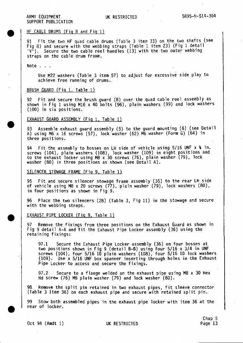
ARMY EQUIPMENT UK RESTRICTED 5895-H-514-304SUPPORT PUBLICATION
HF CABLE DRUMS (Fig 8 and Fig 1)
91 Fit the two HF quad cable drums (Table 3 item 33) on the two shafts (seeFig 8) and secure with the webbing straps (Table 1 item 23) (Fig 1 detail'V'). Secure the two cable reel handles (13) with the two outer webbingstraps on the cable drum frame.
Note
Use M22 washers (Table 3 item 57) to adjust for excessive side play toachieve free running of drums.
BRUSH GUARD (Fig 1, Table 1)
92 Fit and secure the brush guard (8) over the quad cable reel assembly asshown in Fig 1 using M16 x 40 bolts (96), plain washers (99) and lock washers(100) in six positions.
EXHAUST GUARD ASSEMBLY (Fig 1, Table 1)
93 Assemble exhaust guard assembly (5) to the guard mounting (6) (see DetailA) using M6x 16 screws (57), lock washer (62) M6 washer (Form G) (64) inthree positions.
94 Fit the assembly to bosses on LH side of vehicle using 5/16 UNF x ¾ in.screws (104), plain washers (108), lock washer (109) in eight positions andto the exhaust locker using M8 x 30 screws (76), plain washer (79), lockwasher (80) in three positions as shown (see Detail A).
SILENCER STOWAGE FRAME (Fig 9, Table 1)
95 Fit and secure silencer stowage frame assembly (35) to the rear LH sideof vehicle using MS x 20 screws (77), plain washer (79), lock washers (80),in four positions as shown in Fig 9.
96 Place the two silencers (28) (Table 3, Fig 11) in the stowage and securewith the webbing straps.
EXHAUST PIPE LOCKER (Fig 9, Table 1)
97 Remove the fixings from three positions on the Exhaust Guard as shown inFig 9 detail A-A and fit the Exhaust Pipe Locker assembly (36) using theretaining fixings:
97.1 Secure the Exhaust Pipe Locker assembly (36) on four bosses attwo positions shown in Fig 9 (detail B-B) using four 5/16 x 3/4 in UNFscrews (104), four 5/16 ID plain washers (108), four 5/16 ID lock washers(109). Use a 5/16 UNF box spanner inserting through holes in the ExhaustPipe Locker to access and secure the fixings.
97.2 Secure to a flange welded on the exhaust pipe using M8 x 30 HexHd screw (76) M8 plain washer (79) and lock washer (80).
98 Remove the split pin retained in two exhaust pipes, fit sleeve connector(Table 3 Item 36) on each exhaust pipe and secure with retained split pin.
99 Stow both assembled pipes in the exhaust pipe locker with item 36 at therear of locker.
Chap 5Oct 94 (Amdt 1) UK RESTRICTED Page 13
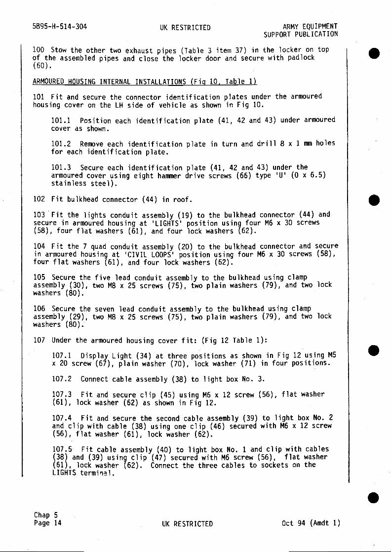
5895-H-514-304 UK RESTRICTED ARMY EQUIPMENTSUPPORT PUBLICATION
100 Stow the other two exhaust pipes (Table 3 item 37) in the locker on topof the assembled pipes and close the locker door and secure with padlock(60).
ARMOURED HOUSING INTERNAL INSTALLATIONS (Fig 10, Table 1)
101 Fit and secure the connector identification plates under the armouredhousing cover on the LH side of vehicle as shown in Fig 10.
101.1 Position each identification plate (41, 42 and 43) under armouredcover as shown.
101.2 Remove each identification plate in turn and drill 8 x 1 mm holesfor each identification plate.
101.3 Secure each identification plate (41, 42 and 43) under thearmoured cover using eight hammer drive screws (66) type 'U' (0 x 6.5)stainless steel).
102 Fit bulkhead connector (44) in roof.
103 Fit the lights conduit assembly (19) to the bulkhead connector (44) andsecure in armoured housing at 'LIGHTS' position using four M6 x 30 screws(58), four flat washers (51), and four lock washers (62).
104 Fit the 7 quad conduit assembly (20) to the bulkhead connector and securein armoured housing at 'CIVIL LOOPS' position using four MS x 30 screws (58),four flat washers (61), and four lock washers (62).
105 Secure the five lead conduit assembly to the bulkhead using clampassembly (30), two M8 x 25 screws (75), two plain washers (79), and two lockwashers (80).
106 Secure the seven lead conduit assembly to the bulkhead using clampassembly (29), two M8 x 25 screws (75), two plain washers (79), and two lockwashers (80).
107 Under the armoured housing cover fit: (Fig 12 Table 1):
107.1 Display Light (34) at three positions as shown in Fig 12 using M5x 20 screw (67), plain washer (70), lock washer (71) in four positions.
107.2 Connect cable assembly (38) to light box No. 3.
107.3 Fit and secure clip (45) using M6 x 12 screw (56), flat washer(61), lock washer (62) as shown in Fig 12.
107.4 Fit and secure the second cable assembly (39) to light box No. 2and clip with cable (38) using one clip (46) secured with M6 x 12 screw(56), flat washer (61), lock washer (62).
107.5 Fit cable assembly (40) to light box No. 1 and clip with cab1es(38) and (39) using clip (47) secured with M6 screw (56), flat washer(61), lock washer (62). Connect the three cables to sockets on theLIGHTS terminal.
.Chap 5Page 14 UK RESTRICTED Oct 94 (Amdt 1)

ARMY EQUIPMENT UK RESTRICTED 5895-H-514-304SUPPORT PUBLICATION
107.6 Below each light box write in white capital letters,approximately 5 mm high, the individual light identification, as shown inFig 12, using white ink (111), catalyst (112) and thinners (113).
107.7 Fit cable assembly (Item 239 on Drg No. FV2047933) up into theaudio outlet.
107.8 Solder conductors to contacts as detailed 'in Fig 12.
107.9 Fit gasket (26) and co-axial outlet shell (25) and secure using5/15 in. plain washer (108), lock washer (109), nut (107) in twopositions.
107.10 In third position fit plain washer (108), cover (27), cable tag,lock washer (109) and nut (107).
INSTALLATION CHECKOUT
108 Check the following:
108.1 Check all cables are connected.
108.2 Check all pipes are connected
108.3 Check all screws and nuts are tightened.
PADLOCKS
109 Fit padlocks (60) (6 off) (Fig 8) to secure APU Enclosure doors andvehicle rear door and Exhaust Pipe Locker door. Stow duplicate keys instowage box.
Chap 5Oct 94 (Amdt 1) UK RESTRICTED Page 15

FV 2048701
FV 2048630
FV 2048044
FV 2048050
FV 2048027
FV 2048028
FV 2048033
FV 2048031
FV 2048032
FV 2048846
FV 2048730
FV 2048731
FV 2047957
5340-99-120-8967
FV 990243
FV 705989
FV 705990
FV 2048381
FV 2048458
FV 2048184
FV 2048861
FV 2048862
FV 2050239/1
FV 2050239/2
FV 2050239/3
FV 2048843
Vehicle mountingbracket assembly
Stowage box assembly
Guard exhaust assembly
Guard mounting
Brush guard
Bearing assembly
Handle assembly
Bracket mounting cablereel
Shaft
Spacer
Plate
Lights conduit assembly7 quad conduit assembly
Unit APU interfaceStrap Webbing, type A1¼ x 1¾ in.
Co-axial outlet shellGasket
Captive cover
Clamp assembly
Clamp assembly
Gasket
Display light 24 V DClens, blue illuminated'DOWN', switched 'YES'
Silencer stowage
Exhaust pipe lockerassembly
Cable assembly
Cable assembly
Cable assembly
Identification plateconnectors
Ref. only
Fig 1
Fig 1Fig 1
Fig 1
Fig 1
Fig 1
Fig 1
Fig 1
Fig 1
Fig 1
Fig 10
Fig 10Fig 1
Fig 1
Fig 9Fig 9
Fig 12
Fig 12
Fig 12
Fig 10
Chap 5Page 16 UK RESTRICTED Oct 94 (Amdt 1)
.
5895-H- 514-304
TABLE 1 ITEMS LIST
UK RESTRICTED ARMY EQUIPMENTSUPPORT PUBLICATION
VEHICLE EQUIPMENT INSTALLATION - EXTERNAL(FV 2047934)
FV 2047935
NSN/FV No. Item Qty Remarks
1
3
5
6
8
12
13
14
15
16
17
19
20
21
23
25
26
27
29
30
32
34
35
36
38
39
40
41
.
.
.
1
1
1
1
1
4
2
4
2
4
4
1
1
I4
1
1
1
2
2
1
3
1
1
1
1
1
1
Fig
Fig
Fig
Fig
Fig
Fig
Fig
12
12
12
10
10
1
12
108
109
110
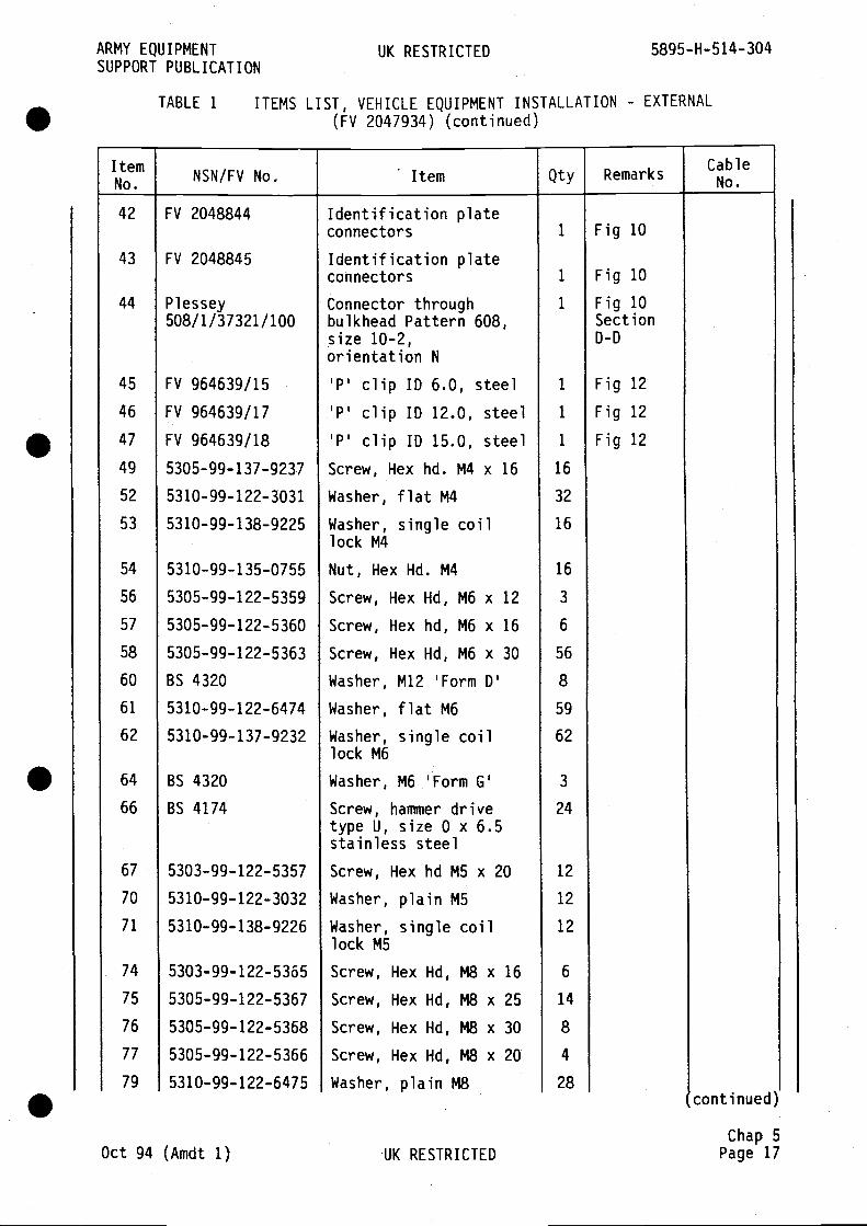
ARMY EQUIPMENT UK RESTRICTED 5895-H-514-304SUPPORT PUBLICATION
TABLE 1 ITEMS LIST, VEHICLE EQUIPMENT INSTALLATION - EXTERNAL(FV 2047934) (continued)
No. NSN/FV No. Item Qty Remarks
42 FV 2048844 Identification plateconnectors 1 Fig 10
43 FV 2048845 Identification plateconnectors 1 Fig 10
44 Plessey Connector through 1 Fig 10508/1/37321/100 bulkhead Pattern 608, Section
size 10-2, D-Dorientation N
45 FV 964639/15 'P' clip ID 6.0, steel 1 Fig 12
46 FV 964639/17 'P' clip ID 12.0, steel 1 Fig 12
47 FV 964639/18 'P' clip ID 15.0, steel 1 Fig 12
49 5305-99-137-9237 Screw, Hex hd. M4 x 16 16
52 5310-99-122-3031 Washer, flat M4 32
53 5310-99-138—9225 Washer, single coil 16lock M4
54 5310-99-135-0755 Nut, Hex Hd. M4 16
56 5305-99-122-5359 Screw, Hex Hd, M6 x 12 3
57 5305-99-122-5360 Screw, Hex hd, M6 x 16 6
58 5305-99-122-5363 Screw, Hex Hd, M6 x 30 56
60 BS 4320 Washer, M12 'Form D' 8
61 5310-99-122-6474 Washer, flat M6 59
62 5310-99-137-9232 Washer, single coil 62lock M6
64 BS 4320 Washer, M6 'Form G' 3
66 BS 4174 Screw, hammer drive 24type U, size 0 x 6.5stainless steel
67 5303-99-122-5357 Screw, Hex hd M5 x 20 12
70 5310-99-122-3032 Washer, plain M5 12
71 5310-99-138-9226 Washer, single coil 12lock M5
74 5303-99-122-5365 Screw, Hex Hd, M8 x 16 6
75 5305-99-122-5367 Screw, Hex Hd, M8 x 25 14
76 5305-99-122-5368 Screw, Hex Hd, M8 x 30 8
77 5305-99-122-5366 Screw, Hex Hd, M8 x 20 4
79 5310-99-122-6475 Washer, plain M8 28continued)
Chap 5Oct 94 (Amdt 1) UK RESTRICTED Page 17
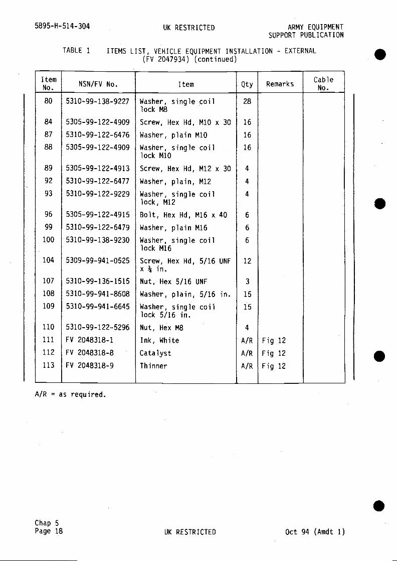
5895-H-514-304 UK RESTRICTED ARMY EQUIPMENTSUPPORT PUBLICATION
A/R = as required.
Chap 5Page 18 UK RESTRICTED Oct 94 (Amdt 1)
.
TABLE 1 ITEMS LIST, VEHICLE EQUIPMENT INSTALLATION - EXTERNAL(FV 2047934) (continued)
ItemNo. NSN/FV No. Item Qty Remarks
CableNo.
Washer, single coillock M8
Screw, Hex Hd, M1O x 30
Washer, plain M1O
Washer, single coillock M1O
Screw, Hex Hd,
Washer, plain,
Washer, singlelock, M12
M12 x 30
M12
coil
80
84
87
88
89
92
93
96
99
100
104
107
108
109
110
111
112
113
5310-99-138-9227
5305-99-122-4909
5310-99-122-6476
5305-99-122-4909
5305-99-122-4913
5310-99-122-6477
5310-99-122-9229
5305-99-122-4915
5310-99-122-6479
5310-99-138—9230
5309-99-941-0525
5310-99-136- 1515
5310-99-941-8608
5310-99-941-6645
5310-99-122-5296
FV 2048318-1
FV 2048318-8
FV 2048318-9
28
16
16
16
4
4
4
6
6
6
12
3
15
15
4
A/R
A/R
A/R
.
.
.
Bolt, Hex Hd, M16 x 40
Washer, plain M16
Washer, single coillock M16
Screw, Hex Hd, 5/16 UNFx ¾ in.
Nut, Hex 5/16 UNF
Washer, plain, 5/16 in.Washer, single coillock 5/16 in.Nut, Hex M8
Ink, White
Catalyst
Thinner
Fig 12
Fig 12
Fig 12
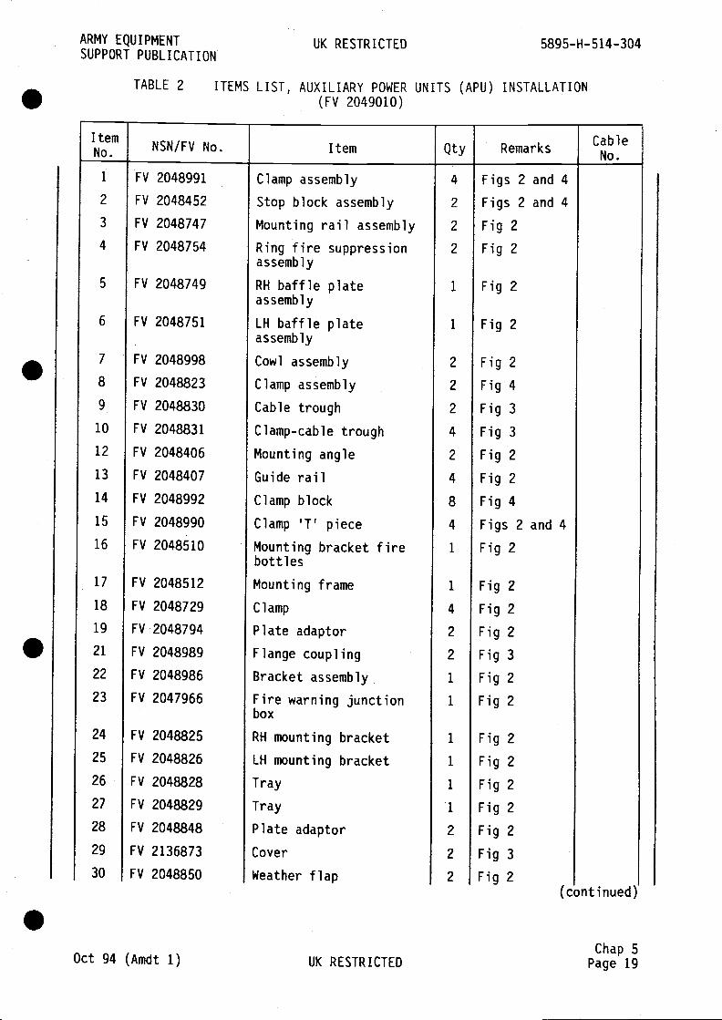
1
2
3
4
5
6
7
8
9
10
12
13
14
15
16
17
18
19
21
22
23
24
25
26
27
28
29
30
FV 2048991
FV 2048452
FV 2048747
FV 2048754
FV 2048749
FV 2048751
FV 2048998
FV 2048823
FV 2048830
FV 2048831
FV 2048406
FV 2048407
FV 2048992
FV 2048990
FV 2048510
FV 2048825
FV 2048826
FV 2048828
FV 2048829
FV 2048848
FV 2136873
FV 2048850
Cowl assembly
Clamp assembly
Cable trough
Clamp-cable trough
Mounting angle
Guide railClamp block
Clamp 'T' piece
Mounting bracket firebottlesMounting frame
Clamp
Plate adaptor
Flange coupling
Bracket assembly
Fire warning junctionbox
Tray
Tray
Plate adaptor
Cover
Weather flap
4
2
2
2
2
2
2
4
2
4
8
4
1
Fig 2
Fig 4
Fig 3
Fig 3
Fig 2
Fig 2
Fig 4
Figs 2 and 4
Fig 2
Oct 94 (Amdt 1) UK RESTRICTEDChap 5
Page 19
ARMY EQUIPMENTSUPPORT PUBLICATION
UK RESTRICTED
TABLE 2 ITEMS LIST, AUXILIARY POWER UNITS (APU) INSTALLATION(Fv 2049010)
5895-H-514-304
NNSN/FV No. Item Qty Remarks
Clamp assembly
Stop block assembly
Mounting rail assembly
Ring fire suppressionassembly
RH baffle plateassembly
LH baffle plateassembly
Figs 2 and 4
Figs 2 and 4
Fig 2
Fig 2
Fig 2
Fig 2
1
1
FV
FV
FV
FV
FV
FV
2048512
2048729
2048794
2048989
2048986
2047966
RH mounting
LH mounting
bracket
bracket
1
4
2
2
1
1
1
1
1
1
2
2
2
Fig 2
Fig 2
Fig 2
Fig 3
Fig 2
Fig 2
Fig 2
Fig 2
Fig 2
Fig 2
Fig 2
Fig 3
Fig 2(continued)
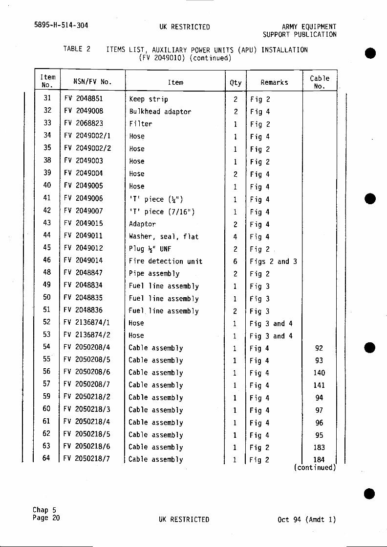
5895-H-514-304 UK RESTRICTED ARMY EQUIPMENTSUPPORT PUBLICATION
TABLE 2 ITEMS LIST, AUXILIARY POWER UNITS (APU) INSTALLATION(FV 2049010) (continued)
No. NSN/FV No. Item Qty Remarks
31 FV 2048851 Keep strip 2 Fig 232 FV 2049008 Bulkhead adaptor 2 Fig 433 FV 2068823 Filter 1 Fig 234 FV 2049002/1 Hose I Fig 435 FV 2049002/2 Hose 1 Fig 238 FV 2049003 Hose 1 Fig 239 FV 2049004 Hose 2 Fig 440 FV 2049005 Hose 1 Fig 441 FV 2049006 '1' piece (¼") 1 Fig 442 FV 2049007 '1' piece (7/16") 1 Fig 443 FV 2049015 Adaptor 2 Fig 444 FV 2049011 Washer, seal, flat 4 Fig 445 FV 2049012 Plug ½" UNF 2 Fig 246 FV 2049014 Fire detection unit 6 Figs 2 and 348 FV 2048847 Pipe assembly 2 Fig 249 FV 2048834 Fuel line assembly 1 Fig 350 FV 2048835 Fuel line assembly 1 Fig 351 FV 2048836 Fuel line assembly 2 Fig 352 FV 2136874/1 Hose 1 Fig 3 and 453 FV 2136874/2 Hose 1 Fig 3 and 454 FV 2050208/4 Cable assembly 1 Fig 4 92
55 FV 2050208/5 Cable assembly 1 Fig 4 93
56 FV 2050208/6 Cable assembly 1 Fig 4 140
57 FV 2050208/7 Cable assembly 1 Fig 4 141
59 FV 2050218/2 Cable assembly 1 Fig 4 94
60 FV 2050218/3 Cable assembly 1 Fig 4 97
61 FV 2050218/4 Cable assembly 1 Fig 4 96
62 FV 2050218/5 Cable assembly 1 Fig 4 95
63 FV 2050218/6 Cable assembly 1 Fig 2 183
64 FV 2050218/7 Cable assembly 1 Fig 2 184(continued)
.Chap 5Page 20 UK RESTRICTED Oct 94 (Amdt 1)
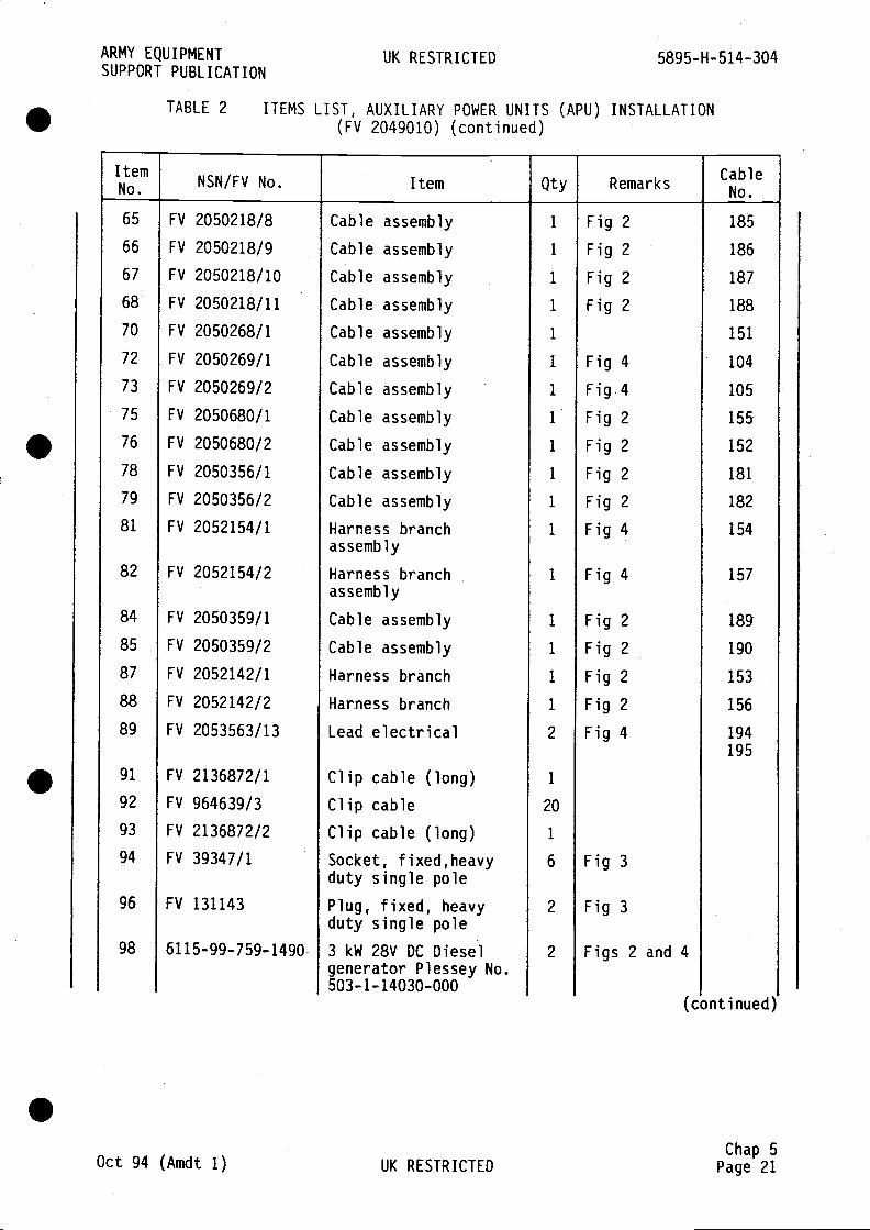
65
66
67
68
70
72
73
75
76
78
79
81
82
84
85
87
88
89
91
92
93
94
96
98
FV 2050218/8
FV 2050218/9
FV 2050218/10
FV 2050218/11
FV 2050268/1
FV 2050269/1
FV 2050269/2
FV 2050680/1
FV 2050680/2
FV 2050356/1
FV 2050356/2
FV 2052154/1
FV 2052154/2
FV 2050359/1
FV 2050359/2
FV 2052142/1
FV 2052142/2
FV 2053563/13
FV 2136872/1
FV 964639/3
FV 2136872/2
FV 39347/1
FV 131143
6115-99-759- 1490
Cable assembly
Cable assembly
Cable assembly
Harness branchassembly
Harness branchassembly
Cable assembly
Cable assembly
Harness branch
Harness branch
Lead electrical
Clip cable (long)Clip cableClip cable (long)Socket, fixed,heavyduty single polePlug, fixed, heavyduty single pole3 kW 28V DC Dieselgenerator Plessey No.503-1 - 14030-000
Fig 2
Fig 2
Fig 2
Fig 2
Fig 4
Fig
Fig 2
Fig 2
Fig 2
Fig
2
Fig
4
185
186
187
188
151
104
105
155
152
181
182
154
157
189
190
153
156
194195
Oct 94 (Amdt 1) UK RESTRICTEDChap 5
Page 21
ARMY EQUIPMENTSUPPORT PUBLICATION
UK RESTRICTED
TABLE 2 ITEMS LIST, AUXILIARY POWER UNITS (APU) INSTALLATION(FV 2049010) (continued)
5895-H- 514-304
No. NSN/FV No. Item Qty Remarks
Cable
Cable
Cable
Cable
Cable
Cable
Cable
Cable
assembly
assembly
assembly
assembly
assembly
assembly
assembly
assembly
1
1
1
1
1
I
1
1
1
1
1
1
1
1
1
1
1
2
1
20
1
6
2
2
Fig 3
Fig 3
Figs 2 and 4
(continued)

5935-99-015—1217
5305-99-135-0417
5305-99-137-7590
BS 3692
BS 3692
5305-99-122-5355
Fire extinguisherGraviner Part No. 57133—005
Mounting bracketGraviner Part No. 58513-005
Cartridge unit GravinerPart No. 58311-004
Lanyard assembly AVDELLtd LT1504-C8-10
Union adaptor bulkhead900 Aeroquip 2043-4-45
Adaptor BSP/BSPAeroquip HO 1260-4
Locking nut Aeroquip HO1270-4
Quick release couplingAeroquip B 5602-4-4
'0' ring (Nitrile)Aeroquip SA 16222/9
Cable tie nylon 4.6 widex 200 long Insuloid T5OR
Grease extreme pressureXG-287 DID 5598
Glandnut Graviner PartNo. 31731—303
Ferrule. Graviner PartNo. 27433-821
terminal ring tongueBICCON CAT No. BG-R4
Protective cap for fixedconnector size 14
Screw pan hd M3 x 12 ig
Screw hex hd M4 x 25 ig
Screw hex hd M4 x 35 ig
Screw hex hd M4 x 45 lg
Screw hex hd M5 x 10 lg
8
12
4
4
18
Chap 5Page 22 UK RESTRICTED Oct 94 (Amdt 1)
.
5895-H- 514-304 UK RESTRICTED
TABLE 2 ITEMS LIST, AUXILIARY POWER UNITS(FV 2049010) (continued)
ARMY EQUIPMENTSUPPORT PUBLICATION
(APU) INSTALLATION
ItemNSN/FV No. Item Qty Remarks
100
102
104
106
108
111
113
115
117
119
121
123
125
127
129
133
137
138
139
142
.
.
S
2
2
2
4
2
2
2
2
2
A/R
A/R
12
12
24
1
Figs 2 and4
Fig 2
Fig 2
Figs 2 and4
Fig 3
Fig 3
Fig 3
Fig 3
Fig 3
Fig 2
(continued)
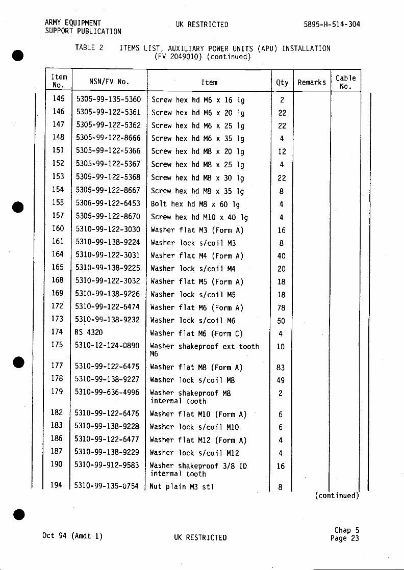
145
146
147
148
151
152
153
154
155
157
160
161
164
165
168
169
172
173
174
175
177
178
179
182
183
186
187
190
194
5305-99-135-5360
5305-99-122-5361
5305-99-1?2-5362
5305-99-122-8666
5305-99-122-5366
5305-99-122- 5367
5305-99-122-5368
5305-99-122-8667
5306-99-122-6453
5305-99-122-8670
5310-99-122-3030
5310-99-138-9224
5310-99-122-3031
5310-99-138-9225
5310-99-122- 3032
5310-99-138-9226
5310-99-122-6474
5310-99-138-9232
BS 4320
5310- 12-124-0890
5310-99-122-6475
5310-99-138-9227
5310-99—636-4996
5310-99-122-6476
5310-99-138-9228
5310-99-122-6477
5310-99-138-9229
5310-99—912-9583
5310-99—135-0754
Screw hex hd M6 x 16 ig
Screw hex hd M6 x 20 ig
Screw hex hd M6 x 25 ig
Screw hex hd M6 x 35 ig
Screw hex hd M8 x 20 lg
Screw hex hd M8 x 25 ig
Screw hex hd M8 x 30 ig
Screw hex hd M8 x 35 ig
Bolt hex hdM8x6O lgScrew hex hd M10 x 40 lg
M3 (Form A)
s/coil M3M4 (Form A)
2
22
22
4
12
4
22
8
4
4
16
8
40
20
18
18
78
50
4
10
83
49
2
6
6
4
4
16
8
Oct 94 (Amdt 1) UK RESTRICTEDChap 5
Page 23
ARMY EQUIPMENTSUPPORT PUBLICATION
UK RESTRICTED
TABLE 2 ITEMS LIST, AUXILIARY POWER UNITS(FV 2049010) (continued)
5895-H-514-304
(APU) INSTALLATION
No. NSN/FV No. Item Qty Remarks
Washer flat
lock
flatlock
flatlock
flat
Washer
Washer
Washer
Washer
Washer
Washer
Washer
Washer
WasherM6
s/coil M4M5 (Form A)
s/coil MS
M6 (Form A)
lock s/coil M6flat M6 (Form C)
shakeproof ext tooth
Washer flat M8 (Form A)
Washer lock s/coil M8
Washer shakeproof M8internal toothWasher
Washer
Washer
Washer
flat M10 (Form A)
lock s/coil M10flat M12 (Form A)
lock s/coil M12Washer shakeproof 3/8 IDinternal toothNut plain M3 sf1
(continued)

5895-H-514-304 UK RESTRICTED ARMY EQUIPMENTSUPPORT PUBLICATION
TABLE 2 ITEMS LIST, AUXILIARY POWER UNITS (APU) INSTALLATION(Fv 2049010) (continued)
NSN/FV No. Item Qty Remarks Cable
196 5310—99-135-0755 Nut plain M4 steel 20
199 5310—99-122-5295 Nut plain M6 36
201 5310—99-122-5296 Nut plain M8 34
203 5310-99-122-5297 Nut plain M1O 2
205 5310-99-122-5298 Nut plain M12 4
UK RESTRICTED Oct 94 (Amdt 1)
.
.
.Chap 5Page 24
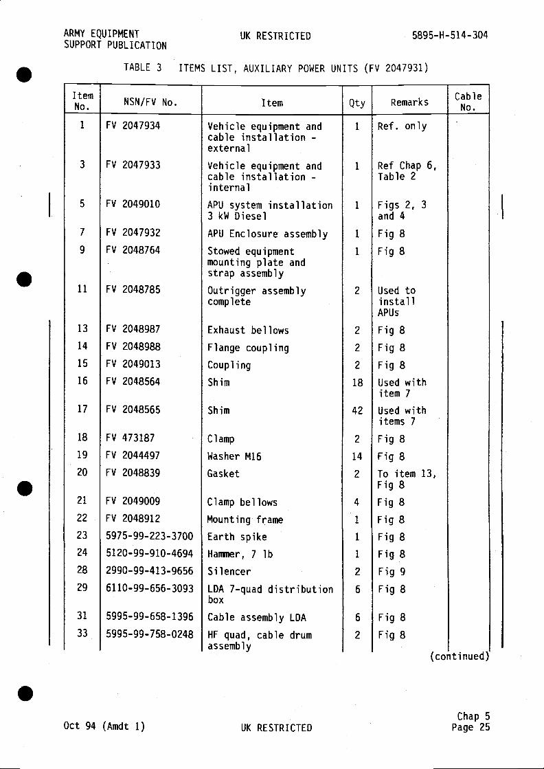
ARMY EQUIPMENT UK RESTRICTED 5895-H-514-304SUPPORT PUBLICATION
TABLE 3 ITEMS LIST, AUXILIARY POWER UNITS (FV 2047931)
ItemNo. NSN/FV No. Item Qty Remarks
CableNo.
1 FV 2047934 Vehicle equipment and 1 Ref. onlycable installation -external
3 FV 2047933 Vehicle equipment and 1 Ref Chap 6,cable installation - Table 2internal
5 FV 2049010 APU system installation 1 Figs 2, 3
3 kW Diesel and 4
7 FV 2047932 APIJ Enclosure assembly 1 Fig 89 FV 2048764 Stowed equipment 1 Fig 8
mounting plate andstrap assembly
11 FV 2048785 Outrigger assembly 2 Used tocomplete install
APU5
13 FV 2048987 Exhaust bellows 2 Fig 814 FV 2048988 Flange coupling 2 Fig 815 FV 2049013 Coupling 2 Fig 816 FV 2048564 Shim 18 Used with
item 717 FV 2048565 Shim 42 Used with
items 718 FV 473187 Clamp 2 Fig 819 FV 2044497 Washer M16 14 Fig 820 FV 2048839 Gasket 2 To item 13,
Fig 821 FV 2049009 Clamp bellows 4 Fig 822 FV 2048912 Mounting frame 1 Fig 823 5975-99-223-3700 Earth spike 1 Fig 824 5120-99-910-4694 Hanuner, 7 lb 1 Fig 828 2990-99-413-9656 Silencer 2 Fig 929 6110—99-656-3093 LDA 7-quad distribution 6 Fig 8
box
31 5995-99-658-1396 Cable assembly LDA 6 Fig 833 5995—99-758-0248 HF quad, cable drum 2 Fig 8
assembly(continued)
Chap 5Oct 94 (Amdt 1) UK RESTRICTED Page 25

5895-H-514-304 UK RESTRICTED ARMY EQUIPMENTSUPPORT PUBLICATION
A/R = as required
TABLE 3 ITEMS LIST, AUXILIARY POWER UNITS(FV 2047931) (continued)
Chap 5Page 26 UK RESTRICTED Oct 94 (Amdt 1)
.
.
ItemNSN/FV No. Item Qty Remarks
34 5995-99-661-7001 DC cable drum assembly 1 Fig 8
36 FV 2048817 Sleeve connector,exhaust pipe
2 Fig 9
37 2990-99-901-8046 Exhaust pipe 4 Fig 9
38 5305-99-122-6440 Screw, Hex Hd, M6 x 40 8
41 5305-99-122-5366 Screw, Hex Hd, M8 x 20 4
42 5305-99-122-8685 Screw, Hex Hd, M16 x 50 14
44 5305-99-122-5365 Screw, Hex Hd, M8 x 16 3
50 5310-99-135-9301 Washer, single coillock M6
8
51 5310-99-135-9302 Washer, single coillock M8
7
52 5310-99-135-9305 Washer, single coillock M16
14
55 5310-99-122-6474 Washer, flat M6 8
56 5310-99-122-6475 Washer, flat M8 7
57 5310-99-122-8055 Washer, plain M22 A/R
60 5340-99-423-3434 Padlock 7
65 6145-99-038-2658 Lead electrical 1
.

AR
MY
EQ
UIP
ME
NT
SU
PP
OR
T P
UB
LIC
AT
ION
UK
RE
ST
RIC
TE
D58
95-H
-514
-304
RE
FE
R T
O T
AB
LE 1
SH
IM IT
EM
SO
TO
BE
FIT
TE
D W
HE
RE
RE
QU
IRE
D T
OP
RE
VE
NT
DIS
TO
RT
ION
OF
ST
OW
AG
E B
OX
Fig
1
Oct
94
(Am
dt 1
)
AP
U in
terf
ace
unit
(FV
204
7934
She
et 1
)
UK
RE
ST
RIC
TE
D
Fig
I
Cha
p 5
Pag
e 27
/28

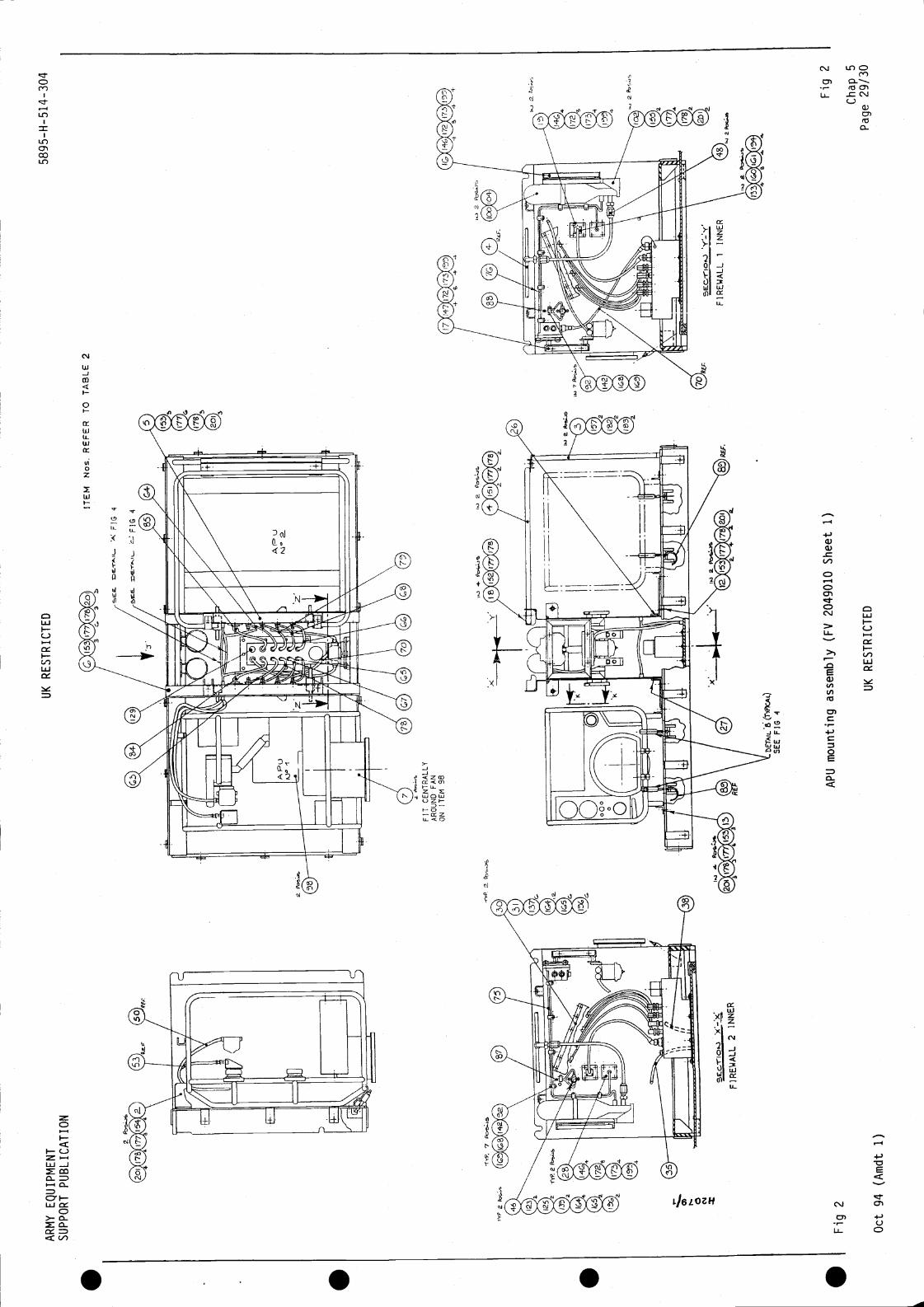
AR
MY
EQ
UIP
ME
NT
SU
PP
OR
T P
UB
LIC
AT
ION
UK
RE
ST
RIC
TE
D58
95-H
-514
-304
UK
RE
ST
RIC
TE
D
Fig
2
Cha
p 5
Pag
e 29
/30
ITE
M N
os. R
EF
ER
TO
TA
BLE
2
1W
FIT
CE
NT
RA
LLY
AR
OU
ND
FA
NO
N IT
EM
96
a
2 W
NE
R
Fig
2
Oct
94
(Am
dt 1
)
a
AP
U m
ount
ing
asse
mbl
y (F
V 2
0490
10 S
heet
1)
FiR
EW
ALL
1IN
NE
R

S S S S
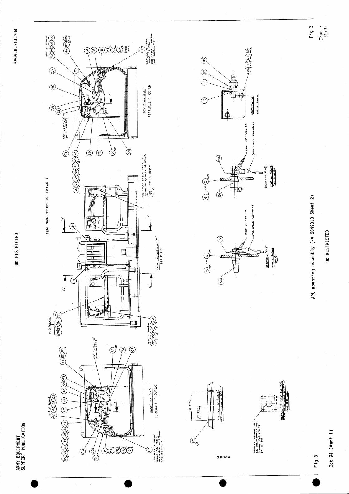
AR
MY
EQ
UIP
ME
NT
SU
PP
OR
T P
UB
LIC
AT
ION
UK
RE
ST
RIC
TE
D58
95-H
-514
-304
ITE
M N
os. R
EF
ER
TO
TA
BLE
2
rC
MLL
2.
C &
UK
RE
ST
RIC
TE
DO
ct 9
4 (A
mdt
1)
iW.
ci.
FIR
EW
ALL
2 O
UT
ER
—
GE
E.
MS
EE
FIG
2
nE. W
RA
P1O
-H
FIR
EW
ALL
1O
UT
ER
a1Y
P. 0
3
rD
0 0 3
OF
•F
ig
P&
AP
U m
ount
ing
asse
mbl
y (F
V 2
0490
10 S
heet
2)F
ig 3
Cha
p 5
31/3
2

. . . .
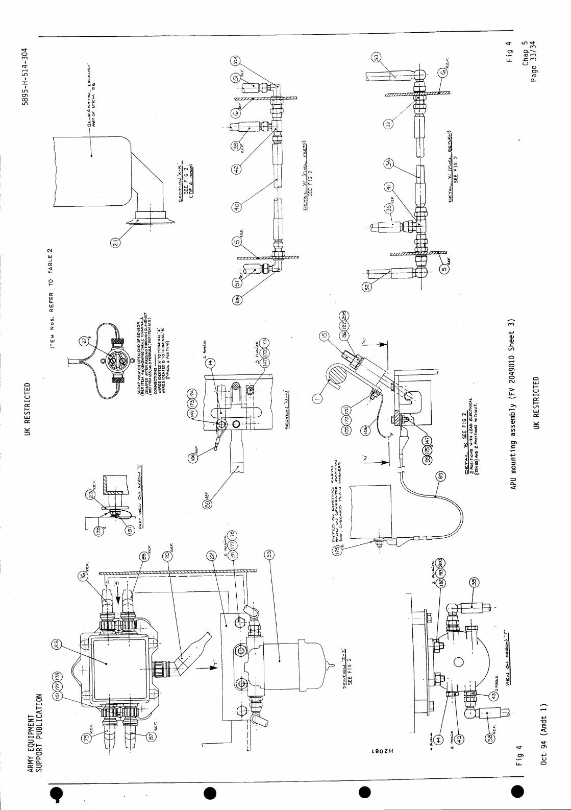
AR
MY
EQ
UIP
ME
NT
SU
PP
OR
T P
UB
LIC
AT
ION
Fig
4
Oct
94
(Arn
dt 1
)
UK
RE
ST
RIC
TE
D
ITE
M N
OS
. RE
FE
RT
O T
AB
LE 2
SC
RA
P V
IEW
OW
OP
ENENDOFSEWSOR
(RE
F. I
TE
M46)514OWII4G
CA
BLE
TE
RM
INA
LSC
RIM
PE
D A
FI'E
P.
CLA
NO
NU
T(R
EF
ITE
M 1
23)A
NOFEPRULE(REF.
125)
CO
NN
EC
TiO
NS—
WIR
ES
IDE
NT
ED
AT
OT
ER
MIN
AL'
A'
WIR
ES
TE
RM
INA
L' B
!(T
YP
ICA
L 6
UK
RE
ST
RIC
TE
D
5895
-H-5
14-
304
Fig
4
Cha
p 5
Pag
e 33
/34
PA
RT
SE
E F
IG 2
(-riP
s.
SE
E F
IG 2
LI -
LI
0.4
0.-)
0 N I 4
FIG
2
POSNS.
SE
E F
IG2
2P
oSIT
ION
S V
JIT
h LE
Ab
ELE
CT
RIC
AL
(IT
EN
as)
MB
Z P
oSIT
ION
SWITMOIIT.
SE
E F
IG 2
AP
LJ m
ount
ing
asse
mbl
y (F
V 2
0490
10S
heet
3)

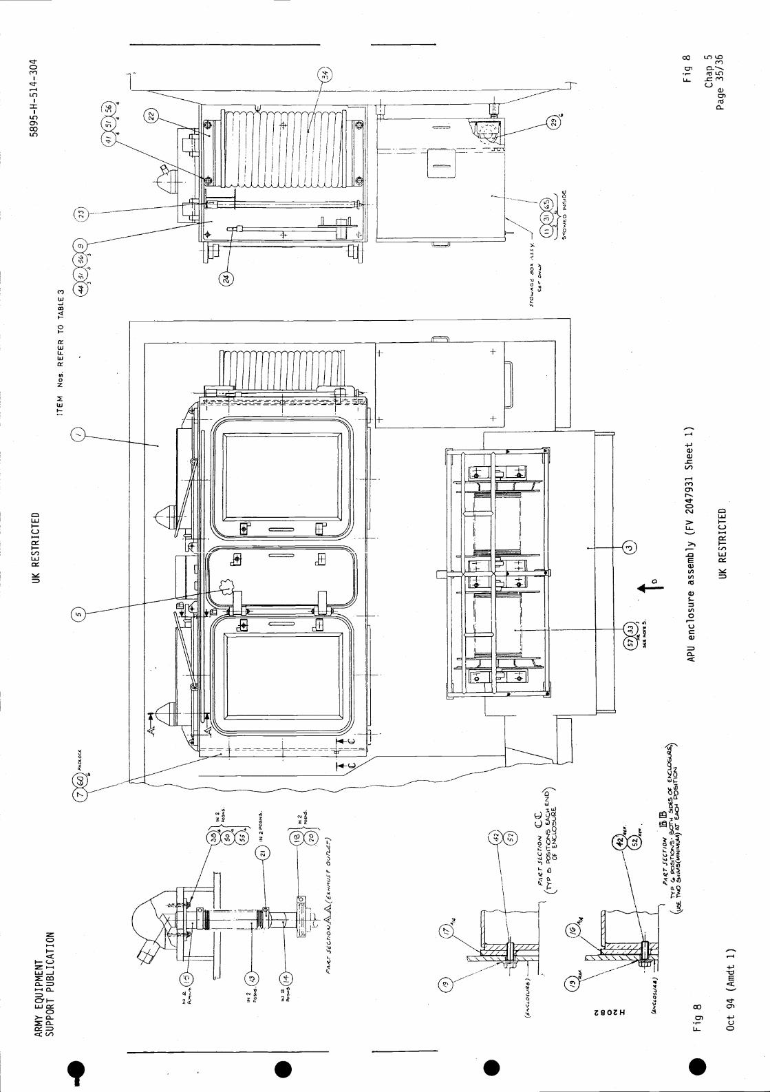
AR
MY
EQ
UIP
ME
NT
SU
PP
OR
T P
UB
LIC
AT
ION
UK
RE
ST
RIC
TE
D58
95-H
-514
-304
(__
rre
ITE
MN
os. R
EF
ER
TO
TA
BLE
3
oO
F
80'
to
Fig
8A
PU
enc
losu
re a
ssem
bly
(FV
204
7931
She
et 1
)
Oct
94
(Am
dt 1
)U
K R
ES
TR
ICT
ED
Fig
8
Cha
p S
Pag
e 35
/36

. . .
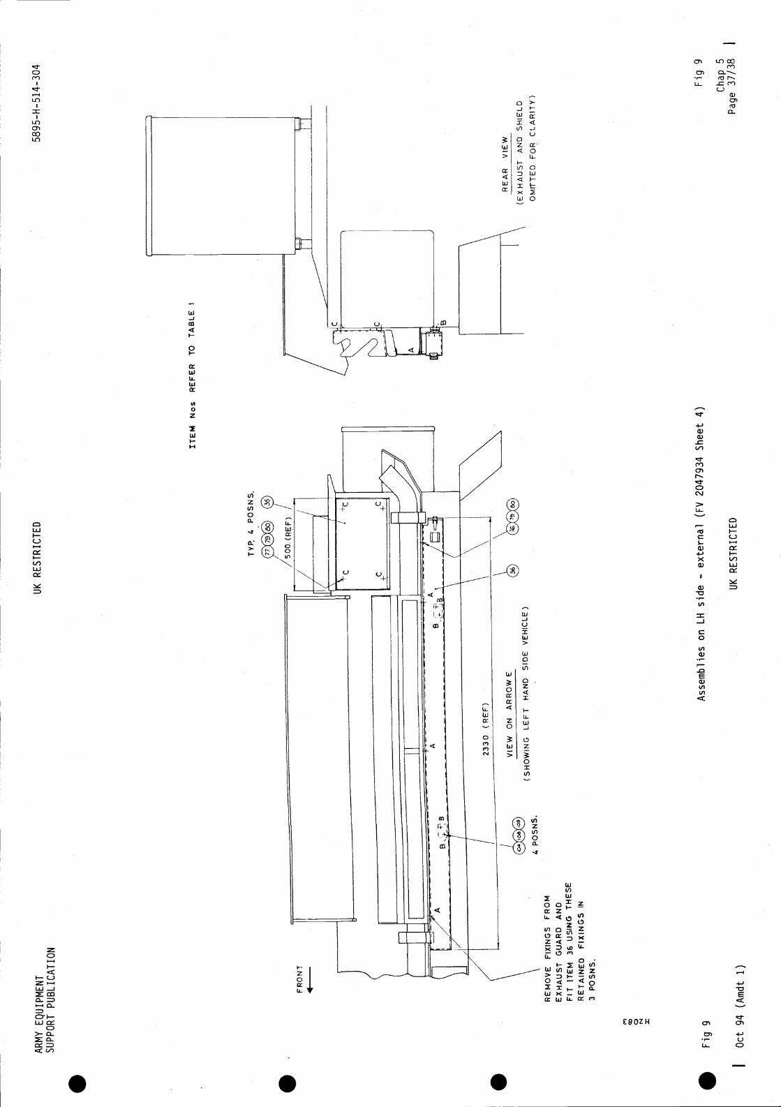
AR
MY
EQ
UIP
ME
NT
SU
PP
OR
T P
UB
LIC
AT
ION
0 x
RE
MO
VE
FIX
ING
S F
RO
ME
XH
AU
ST
GU
AR
D A
ND
FIT
ITE
M 3
6 U
SIN
G T
HE
SE
RE
TA
INE
D F
IXIN
GS
IN3
PO
SN
S.
UK
RE
ST
RIC
TE
D58
95-H
-514
-304
TY
P. 4
PO
SN
S.
Ass
embl
ies
on L
H s
ide
- ex
tern
al (
FV
204
7934
She
et 4
)F
ig 9
IO
ct 9
4 (A
mdt
1)
UK
RE
ST
RIC
TE
D
FR
ON
T4
ITE
M N
os R
EF
ER
TO
TA
BLE
1
(SH
OW
ING
LE
FT
HA
ND
SID
E V
EH
ICLE
Fig
9
RE
AR
VIE
W
(EX
HA
US
T A
ND
SH
IELD
OM
rrT
ED
FO
R C
LAR
ITY
)
Cha
p 5
Pag
e 37
/38

S S S S


. . . .
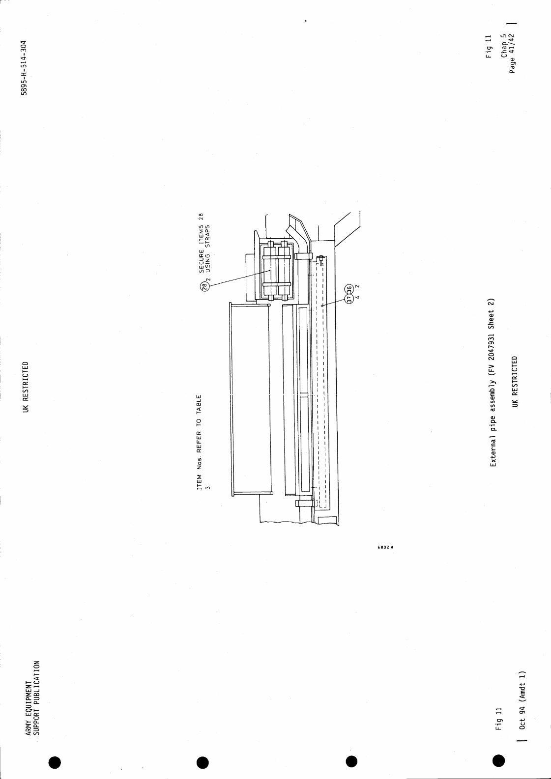
AR
MY
EQ
UIP
ME
NT
SU
PP
OR
T P
UB
LIC
AT
ION
0 m
UK
RE
ST
RIC
TE
D58
95-H
-514
-304
Ext
erna
l pip
e as
sem
bly
(FV
204
7931
She
et2)
UK
RE
ST
RIC
TE
D
Fig
11
Cha
p 5
Pag
e 41
/42
ITE
M N
os. R
EF
ER
TO
TA
BLE
SE
CU
RE
ITE
MS
28
US
ING
ST
RA
PS
Fig
11
Oct
94
(Am
dt 1
)

4
. . . .
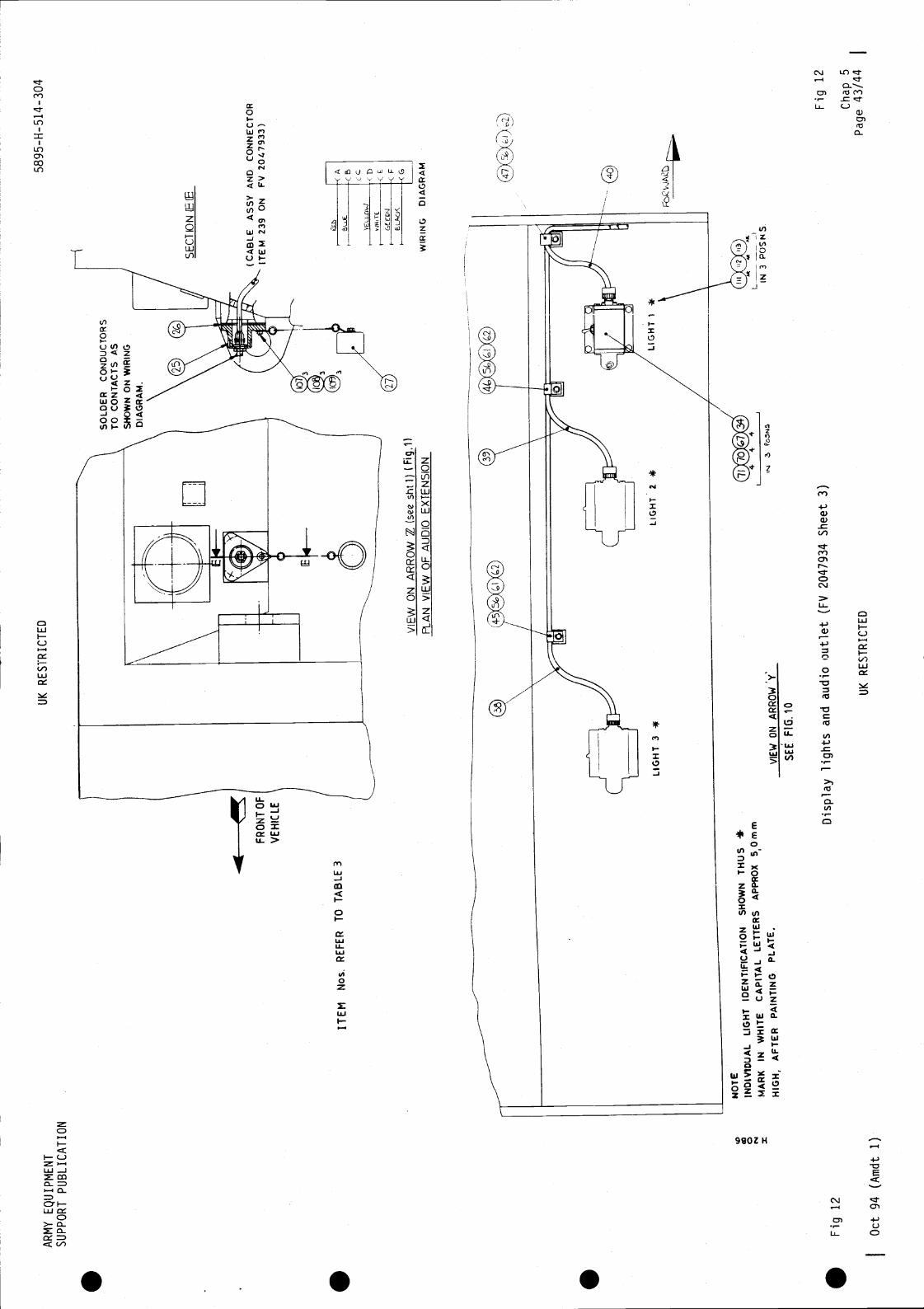
SE
E F
IG. 1
0
-
(C
£
<F
Fig
12
Oct
94
(Am
dt 1
)
Dis
play
ligh
ts a
nd a
udio
out
let (
FV
2047
934
She
et 3
)
UK
RE
ST
RIC
TE
D
Fig
12
Cha
p 5
Pag
e 43
/44
AR
MY
EQ
UIP
ME
NT
SU
PP
OR
T P
UB
LIC
AT
ION
UK
RE
ST
RIC
TE
D
SO
LDE
R C
ON
DU
CT
OR
ST
o C
ON
TA
CT
S A
SS
HO
WN
ON
WIR
ING
DIA
GR
AM
.
FR
ON
T O
F
VE
HIC
LE
ITE
MN
os, R
EF
ER
TO
TA
BLE
3
5895
-H-5
14-3
04
SE
CT
KJN
(CA
BLE
ASSY AND CONNECTOR
ITEM 239 ON
FV 2047933)
VIE
W O
N A
RR
OW
(see
sht
l) (F
ig.'l
)P
LAN
VIE
W O
F A
UD
IO E
XT
EN
StO
NW
IRIN
GD
IAG
RA
M
NO
TE
IND
IVID
UA
L LI
GH
TID
EN
TIF
ICA
TIO
NS
HO
WN
TH
US
*
MA
RK
IN W
HIT
EC
AP
ITA
L LE
TT
ER
SA
PP
RO
X 5
0mm
HIG
H, A
FT
ER
PA
INT
ING
PLA
TE
.V
IEW
ON
AR
RO
WIN
3 P
OS
NS
.

. . . .
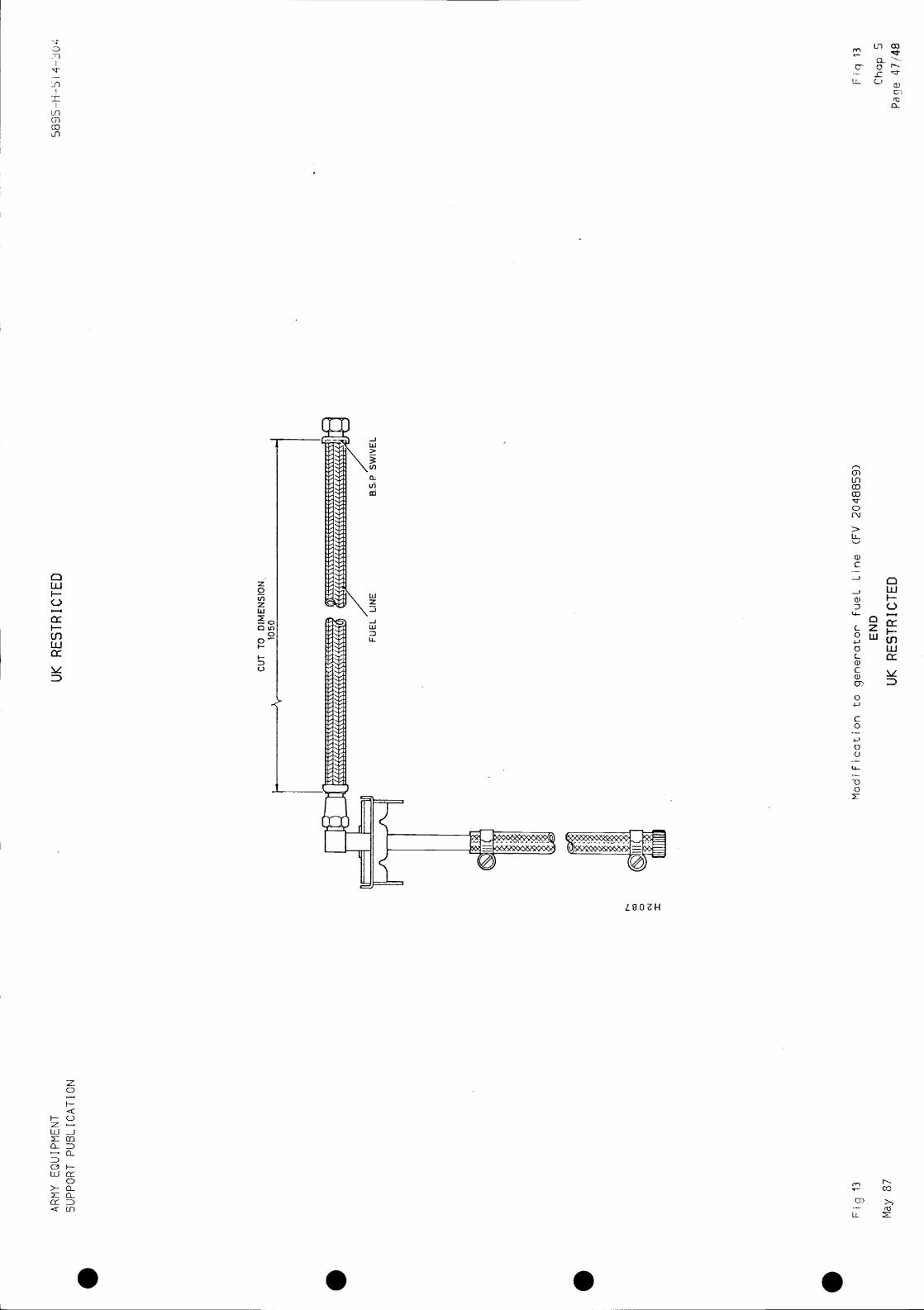

. . . .

ARMY EQUIPMENT UK RESTRICTED 5895-H-514-304SUPPORT PUBLICATION
Chapter 6
INTERNAL INSTALLATION
CONTENTS
Par a1 Introduction4 Floor plates5 Auxiliary box6 APU battery vent pipe7 Air conditioning ducting8 NBC control cables
Brackets, cable trunking, mounting plates and assemblies9 Rear bulkhead and roof internal
10 LH side rear (internal)11 LH side forward (internal)13 LH side rear (internal)14 Cross bulkhead15 Floor mounted equipment16 Assembly of ULS equipment17 RH side forward and rear18 Rear wall and door19 CLANSMAN equipment20 Roof and armoured housing21 Cross bulkhead24 RH side internal27 Cable trunking covers28 PTARMIGAN equipment35 Rear bulkhead36 Transom43 Secondary Packet Switch Unit (SPS)44 Static Sub Set46 Single Engineering Order Wire Unit (SEOW)47 Seat49 Teleprinter, FAX PSU mounting assemblies51 Stowage box and Teleprinter mounting frame52 Seat and Teleprinter tray59 Batteries and battery venting assemblies61 NBC batteries floor forward position62 Communications batteries, RH sill63 APU batteries, floor forward64 Loose items65 Installation check-out and test
Table Page
1 Intercom system, cable routeing 12
2 Items list, clamp assemblies (Fig 15) ... 13
3 Items list, floor plates, mounting brackets and plates (FV 2047935) 29
4 Items list, equipment and cable installation (FV 2047933) 39
5 List of cables ... . 52
Chap 6May 87 UK RESTRICTED Page
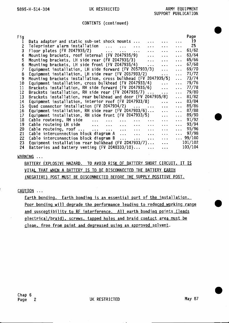
5895-H-514-304 UK RESTRICTED ARMY EQUIPMENTSUPPORT PUBLICATION
CONTENTS (continued)
Fig Page1 ... 19
2 ... 253 ... 61/624 ... 63/645 ... 65/666 ... 67/687 ... 69/708 ... 71/729 ... 73/74
10 ... 75/7611 ... 77/7812 ... 79/8013 ... 81/8214 ... 83/8415 ... 85/8616 ... 87/8817 ... 89/9018 ... 91/9219 ... 93/9420 ... 95/9621 ... 97/9822 ... 99/10023 101/10224 103/104
WARNING
BATTERY EXPLOSIVE HAZARD. TO AVOID RISK OF BATTERY SHORT CIRCUIT, IT IS
VITAL THAT WHEN A BATTERY IS TO BE DISCONNECTED THE BATTERY EARTH
(NEGATIVE) POST MUST BE DISCONNECTED BEFORE THE SUPPLY POSITIVE POST.
CAUTION
Chap 6Page 2 UK RESTRICTED May 87
Data adaptor and static sub-set shock mounts ...Teleprinter alarm installation ... ... ...Floor plates (FV 2047935/2) ... ... ...Mounting brackets, roof internal (FV 2047935/9)Mounting brackets, LH side rear (FV 2047935/3)Mounting brackets, LH side front (FV 2047935/4)Equipment installation, LH side forward (FV 2057933/3)Equipment installation, LH side rear (FV 2057933/2)Mounting brackets installation, cross bulkhead (FV 2047935/5)Equipment installation, cross bulkhead (FV 2047933/4)Brackets installation, RH side forward (FV 2047935/6)Brackets installation, RH side rear (FV 2047935/7)Brackets installation, rear bulkhead and door (FV 2047935/8)Equipment installation, interior roof (FV 2047933/8)Quad connector installation (FV 2047934/2) ...Equipment installation, RH side rear (FV 2047933/6)...Equipment installation, RH side front (FV 2047933/5)Cable routeing, RH side ... ... ... ...Cable routeing LH side ... ... ... ...Cable routeing, roof ... ... ... ... ...Cable interconnection block diagram A ... ...Cable interconnection block diagram B ... ...Equipment installation rear bulkhead (FV 2047933/7)...Batteries and battery venting (FV 2048333/10)...
.
Earth bondino. Earth bondina is an essential Dart of the installation.Poor bonding will degrade the performance leading to reduced working range Sand susceptibility to RF interference. All earth bonding points (leadselectrical/braid), screws, tapped holes and braid contact area must beclean, free from paint and degreased using an approved solvent.
.
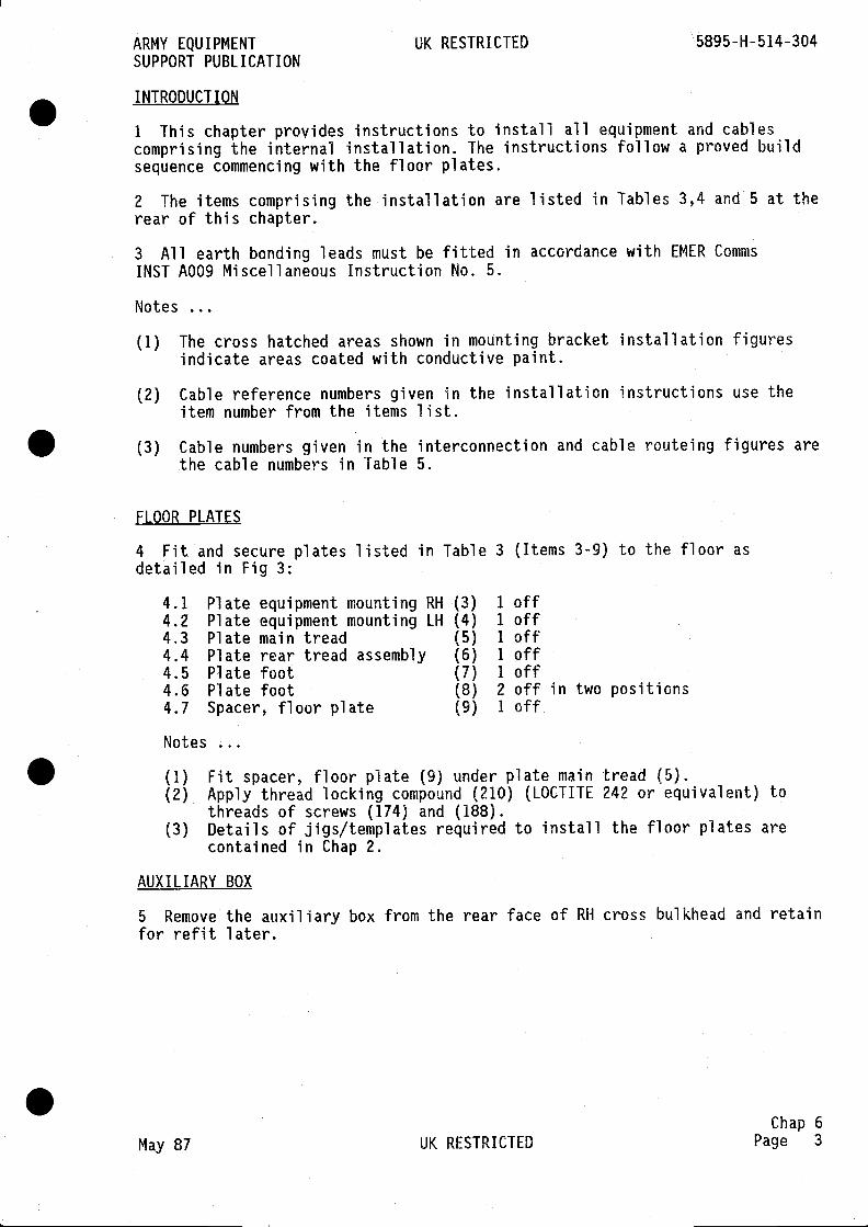
ARMY EQUIPMENT UK RESTRICTED 5895-H-514-304SUPPORT PUBLICATION
INTRODUCTION
1 This chapter provides instructions to install all equipment and cablescomprising the internal installation, The instructions follow a proved buildsequence commencing with the floor plates.
2 The items comprising the installation are listed in Tables 3,4 and 5 at therear of this chapter.
3 All earth bonding leads must be fitted in accordance with EMER CommsINST A009 Miscellaneous Instruction No. 5.
Notes
(1) The cross hatched areas shown in mounting bracket installation figuresindicate areas coated with conductive paint.
(2) Cable reference numbers given in the installation instructions use theitem number from the items list.
(3) Cable numbers given in the interconnection and cable routeing figures arethe cable numbers in Table 5.
FLOOR PLATES
4 Fit and secure plates listed in Table 3 (Items 3-9) to the floor asdetailed in Fig 3:
4.1 Plate equipment mounting RH (3) 1 off4.2 Plate equipment mounting LH (4) 1 off4.3 Plate main tread (5) 1 off4.4 Plate rear tread assembly (6) 1 off4.5 Plate foot (7) 1 off4.6 Plate foot (8) 2 off in two positions4.7 Spacer, floor plate (9) 1 off
Notes
(1) Fit spacer, floor plate (9) under plate main tread (5).(2) Apply thread locking compound (210) (LOCTITE 242 or equivalent) to
threads of screws (174) and (188).(3) Details of jigs/templates required to install the floor plates are
contained in Chap 2.
AUXILIARY BOX
5 Remove the auxiliary box from the rear face of RH cross bulkhead and retainfor refit later.
Chap 6May 87 UK RESTRICTED Page 3

5895-H-514-304 UK RESTRICTED ARMY EQUIPMENTSUPPORT PUBLICATION
APU BATTERY VENT PIPE
6 Refer to Table 4 and Fig 24 for detail of battery vent pipe (504).
6.1 Connect vent pipe (504) to flame trap above cross bulkhead. Ifnecessary remove and rotate flame trap to align with vent pipe.
6.2 Fit eight clips (existing) on the vent pipe and fit to bosses ontransom and on rear face of RH cross bulkhead as shown in Fig 24.
6.3 Fit one clip on pipe and fit on stud on RH sill.
6.4 Route pipe around bracket on forward RH sloping sill as shown inFig 24. Leave pipe loose until battery is installed.
AIR CONDITIONING DUCTING
7 Refit the ducting previously removed from the RH side and shown in Fig 4.
NBC CONTROL CABLES
8 Connect the NBC control cables (341) and (343) to the NBC control unit onthe RH wall. Route cable (343) through cross bulkhead and connect to vehicledistribution panel No. 6. Connect cable 341 to NBC unit. Items 341 and 343are in Table 4.
BRACKETS, CABLE TRUNKING. MOUNTING PLATES AND ASSEMBLIES
Rear bulkhead and roof internal
9 Refer to Fig 4 and Table 3, except where otherwise stated, to install thefollowing items on the rear bulkhead and roof, internal:
9.1 Trunking cable (94) using M6 x 10 panhead screws (168), lock washer(195), flat washer (200) in four positions.
9.2 Take mounting plate roof (53) from brackets pack and fit two shockmounts (113) as shown in Fig 9 using four M5 x 25 screws (214), eight plainwashers (213) and four Nylock nuts (212) in two positions.
9.3 Fit mounting, plate roof (53) to roof using two UNF x screw (143),lock washers (151), flat washer (153).
9.4 Fit the air duct blanking plate (76) on sloping cross bulkhead andspot through in two positions using 3.2 mm drill. Secure using No. 8 xin. self tapping screws (216).
9.5 Mounting plate assembly (40) to roof, forward of hatch, using 5/16 UNFx in. screws (135), lock washer (196), flat washer (201) in fourpositions.
9.6 Trunking cable (87) to above forward LH sill using M6 x 12 pan headscrew (169), lock washer (195), flat washer (200) in four positions.
9.7 Clamp assembly (105), above LH sill, using M6 x 16 screw (179), lockwasher (195), flat washer (200) in outer position (see Fig 4), and screw(179), and two internal teeth shakeproof washer (209) at inner position. .
Chap 6Page 4 UK RESTRICTED May 87
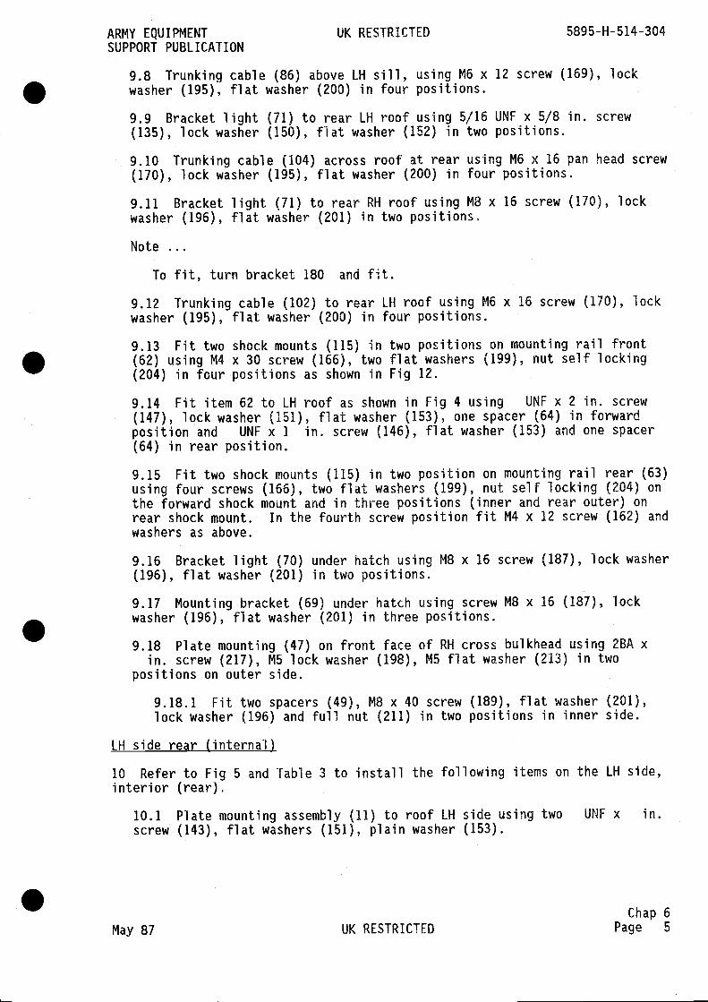
ARMY EQUIPMENT UK RESTRICTED 5895-H-514-304SUPPORT PUBLICATION
9.8 Trunking cable (86) above LH sill, using M6 x 12 screw (169), lockwasher (195), flat washer (200) in four positions.
9.9 Bracket light (71) to rear LH roof using 5/16 UNE x 5/8 in. screw(135), lock washer (150), flat washer (152) in two positions.
9.10 Trunking cable (104) across roof at rear using M6 x 16 pan head screw(170), lock washer (195), flat washer (200) in four positions.
9.11 Bracket light (71) to rear RH roof using MB x 16 screw (170), lockwasher (196), flat washer (201) in two positions.
Note
To fit, turn bracket 180 and fit.
9.12 Trunking cable (102) to rear LH roof using M6 x 16 screw (170), lockwasher (195), flat washer (200) in four positions.
9.13 Fit two shock mounts (115) in two positions on mounting rail front(62) using M4 x 30 screw (166), two flat washers (199), nut self locking(204) in four positions as shown in Fig 12.
9.14 Fit item 62 to LH roof as shown in Fig 4 using UNF x 2 in. screw(147), lock washer (151), flat washer (153), one spacer (64) in forwardposition and UNF x 1 in. screw (146), flat washer (153) and one spacer(64) in rear position.
9.15 Fit two shock mounts (115) in two position on mounting rail rear (63)using four screws (166), two flat washers (199), nut self locking (204) onthe forward shock mount and in three positions (inner and rear outer) onrear shock mount. In the fourth screw position fit M4 x 12 screw (162) andwashers as above.
9.16 Bracket light (70) under hatch using M8 x 16 screw (187), lock washer(196), flat washer (201) in two positions.
9.17 Mounting bracket (69) under hatch using screw M8 x 16 (187), lockwasher (196), flat washer (201) in three positions.
9.18 Plate mounting (47) on front face of RH cross bulkhead using 2BA xin. screw (217), M5 lock washer (198), M5 flat washer (213) in two
positions on outer side.
9.18.1 Fit two spacers (49), M8 x 40 screw (189), flat washer (201),lock washer (196) and full nut (211) in two positions in inner side.
LH side rear (internal)
10 Refer to Fig 5 and Table 3 to install the following items on the LH side,interior (rear).
10.1 Plate mounting assembly (11) to roof LH side using two UNF x in.screw (143), flat washers (151), plain washer (153).
Chap 6May 87 UK RESTRICTED Page 5
5895-H-514-304 UK RESTRICTED ARMY EQUIPMENTSUPPORT PUBLICATION
10.2 Patch panel frame (12) using seven M8 x 16 screws (187), lock washer(196), flat washer (201) at the top and two UNF x in. screws (143),lock washers (151), flat washers (153) in lower position.
10.3 Cable trunking (89) using eight M6 x 20 pan head screws (171), lockwasher (195), flat washers (200).
10.4 Cable trunking (90) using six M6 x 20 pan head screws (171), lockwasher (195), flat washer (200).
10.5 Cable trunking (91) using five M6 x 20 pan head screws (171), lockwashers (195), flat washers (200).
10.6 Fit the four shock mountings provided in the LDA Multiplexer pack(item 522 in Table 4 and shown in Fig 6) on the two brackets on framemounting LDA and LASE (32) using four M5 x 25 screws (426), flat washers(443), lock washers (451) in four positions.
10.7 Frame mounting LDA and LASE (32) on LH sill using nine 5/16 UNF x1 in. screws (139), lock washer (150), flat washer (152).
10.8 Fit LDA Multiplexer mounting assembly (item 522 in Fig 6) on the fourshock mounts fitted on item 32 and secure with the four pan head screwsprovided in pack.
LH side forward (internal)
11 Refer to Fig 4 and Table 3 to install the following items on LH side,forward:
11.1 Mounting angle (48) using two UNF x in. screws (143), lockwashers (151), flat washers (153).
11.2 Mounting plate (44) using four flat washers (153), four lock washers(151) and four nuts (208).
Tray mounting LASE and LASE unit (Figs 1 and 5)
Note
LASE unit (Table 4 item 365) is supplied complete with mounting bars.These are surplus to requirements and should be returned to stores.
11.3 Fit the LASE unit (item 365) on Tray Mounting LASE (Table 3 item 33)prior to installing the assemblies and proceed as follows:
11.3.1 Fit Mounting Bracket (Table 3 item 34) to RH side of item 33 asshown in Fig 4 using four M6 x 16 countersink headed screws (Table 3item 174), flat washers (200) and self locking nuts (205).
11.3.2 Fit Mounting Bracket (item 35) on top RHS of item 33 as shown inFig 4 using fixings detailed in sub-para 11.3.1 above.
11.3.3 Fit LASE unit (Table 4 item 365) in the Mounting Tray (33) asshown in Fig 5 and secure using M8 x 16 screws, flat washers (445) andlock washers (453) in four positions at base of tray and two positionsin slotted holes at back of tray, top position.
Chap 6Page 6 UK RESTRICTED May 87
ARMY EQUIPMENT UK RESTRICTED 5895-H-514-304SUPPORT PUBLICATION
11.4 Position the LASE unit and assembly on the LH sill (Fig 5) and securethe tray to bosses at positions shown in Fig 4 using two M8 x 20 screws(188) fitted with flat washers (201) and lock washers (186). Insert thescrews through the two slotted holes at bottom of tray back plate, accessfrom under the Lase unit.
11.5 Secure the tray to brackets on the sill using MB x 16 screwslock washers (196), four flat washers (201) in positions as shown in Fig 4.
Note
LASE (365) is supplied complete with mounting bars. These are surplus torequirements and should be returned to stores.
11.6 Fit lead electrical (153) (Fig 5 (Table 4)) to screw securingassembly on sloping roof above LASE and to screw securing LH handle on LASEunit using two internal teeth shakeproof washers at each positidn.
12 Refer to Fig 5 and Table 4 to install the following items on LH side,forward:
12.1 Filter protection unit (7) on brackets on RH side of LASE assemblyusing four M6 x 25 screws (433), flat washers (444), lock washers (452) asshown in Fig 5.
12.2 Fit and secure lead electrical (333) to earth terminal on filterprotection unit using two internal teeth washers (459) and M8 nut (465).Secure other end to boss on sill with lead electrical (141).
12.3 ULSIE/ULS Interface (21) on mounting plate on front face of sillusing MB x 45 screw (440), two internal teeth washers (459) in forwardposition and MB screw (440), lock washer (445), flat washer (453) in rearposition.
12.4 Bracket, fire extinguisher (391) on mounting plate on front face ofsill using two M4 x 16 countersunk screws (423) in forward position and twoM4 x 16 countersunk screws (436) in rear position.
12.5 Fit fire extinguisher (389) to bracket.
12.6 Alarm tray assembly (3) on LH sill using two M6 x 16 screws (429),lock washer (452), flat washer (444).
12.7 Fit and secure lead electrical (319) to earth terminal on the alarmtray (3) using two internal teeth washers (458) and nut (464).
LH side rear (internal)
13 Refer to Fig 6 and Table 4 to install the following items on LH side,rear:
13.1 Lay cables (85), (117) and (121) in trunking on rear LH wall androute out and along in trunking below patch panel position.
13.2 Patch panel (26) to mounting bracket on LH rear bulkhead using two M8x 16 screws (438), lock washer (453), flat washers (445) and two MB x 20screws (439), washers (453) and (445) in lower position.
Chap 6May 87 UK RESTRICTED Page 7

5895-H-514-304 UK RESTRICTED ARMY EQUIPMENTSUPPORT PUBLICATION
13.3 Lead electrical (131) to earth terminal on patch panel and to stud onrear LH wall using 5/16 UNF x in. screw (475), two internal teeth washers(459).
Notes
(1) Use screwdriver 4 mm ball tip (400) to release socket headed screwssecuring patch panel cover.
(2) Stow screwdriver in rear teleprinter drawer (when fitted).
Cross bulkhead
14 Refer to Fig 9 and Table 3 to install the following items in the crossbulkhead location:
14.1 Cable trunking (92) using two M6 x 20 pan head screws (171), specialwashers (54), lock washer (195).
14.2 Cable trunking (93) using three screws (171), lockwasher (195), flatwasher (200).
14.3 Screw special (78) into three bosses shown in Fig 9.
14.4 Loosely fit mounting plate, security light (45), using three flatwasher (152) and three 5/16 UNF self locking nuts (156) in upper position,two M8 internal teeth washers (203) and one 5/16 UNF self locking nut (156)in lower position as shown in Fig 9.
14.5 Mounting bracket (46) on mounting plate (45) using three M6 x 16screws (179), lock washer (195), flat washer (200).
14.6 Cable trunking (95) using three M6 x 12 pan head screws (169), lockwashers (195), flat washers (200) into the thread in the three screwsspecial (78).
14.7 Rifle mounting bracket (43) to the ULS main frame assembly (37) usingfour M6 flat washers (200) and four self locking nuts (205).
14.8 ULS main frame assembly (37) using four M10 x 25 screws (191), lockwashers (197), flat washers (202) in the lower positions.
14.9 Loosely fit the ULS mounting frame 38 on item 37 using the eightscrews supplied with frame.
14.10 Rifle mounting tray (42) to floor using two M6 x 16 screws (179),lock washers (195), flat washers (200).
Floor mounted epuiDment
15 Refer to Fig 10 and Table 4 to install the ULSIE equipment on the floor atthe cross bulkhead and proceed as follows:
15.1 If not supplied assembled with mounting tray and shockmounts fitted,fit the four shock mounts to the mounting tray as shown in Fig 10, anddetailed below.
.Chap 6Page 8 UK RESTRICTED May 87
ARMY EQUIPMENT UK RESTRICTED 5895-H-514-304SUPPORT PUBLICATION
15.2 Fit supports (Fig 9)(29) and (30) (Table 3 items) to the four shockmounts on the ULSIE mounting tray using four M4 x 20 screws (421) four lockwashers (450), four flat washers (442) in two positions.
15.3 Position ULSIE assembly on floor and secure the two supports (Fig 9)(Table 3 items 29 and 30) to floor in front of cross bulkhead using two M10x 20 screws (190), lock washer (197), flat washer (202) on each support.
15.4 At stud on LH side of ULSIE mounting tray:
15.4.1 Discard one nut.
15.4.2 Fit lead electrical (137) on stud using two internal teethshakeproof washers (458) and to vehicle using two internal teethshakeproof washers (458) and nut (480).
15.5 Fit lead electrical (141) on boss on LH sill with lead electrical(333) using UNF x in, screw (472) with three internal teeth shakeproofwasher (458).
15.6 Fit lead electrical (143) to boss on cross bulkhead using 5/16 UNF xin. screw (475) and two M8 shakeproof washers (459).
Assembly of ULS ecluiDment
16 Assemble the ULS mounting frame (38) to the ULS 16 line unit (375) and ULS3 line unit (377) as shown in Figs 9 and 10 in the following sequence:
16.1 Remove the ULS mounting frame (38) from the main frame assembly onthe cross bulkhead and retain fixings.
16.2 Remove and retain the two end brackets and retain the eight screwsand washers. Discard the eight nuts.
16.3 Remove and retain the front covers from the ULS 16 line unit and ULS3 line unit. Front covers to be stowed.
16.4 Place both ULS units flat on bench and loosely fit clamping angles(Table 4 Items 79 and 80) in two positions as shown in Fig 10. Discardunits, if supplied.
16.5 Remove the pressure release screw from LH side of ULS 16 line.Ensure the '0' ring remains on the screw.
16.6 Place both units face down on bench and fit mounting frame (38) overunits. Secure with the eight screws and washers previously removed.
16.7 Replace pressure release screw ensuring '0' ring is fitted and isundamaged. If damaged a new '0' ring must be fitted.
16.8 Tighten the M5 screws (420) on the clamping angles between the ULSunits.
16.9 Fit the assembly on to the main frame as shown in Fig 9 and securetwo with M8 x 16 screws (187), lock washers (196), flat washers (201) inthe two top positions. In the RH lower position fit internal teethshakeproof washer (458) and loose end of lead electrical (143), anothershakeproof washer, secure with screw (Fig 10).
Chap 6May 87 UK RESTRICTED Page 9
5895-H-514-304 UK RESTRICTED ARMY EQUIPMENTSUPPORT PUBLICATION
16.10 In the LH lower position fit loose end of lead electrical (141)using two internal teeth shakeproof washers (458) as above and shown inFig 10.
16.11 Fit mounting plate assembly (119) as shown in Fig 9 using screws andwashers existing on the ULS mounting frame brackets.
16.12 Utilize drilled holes in desk stowage tray to secure ULSIE Key Padcable using the wraps (411) as shown in Fig 10.
RH side forward and rear
17 Refer to Figs 11 and 12 and Table 3 to fit the following items on the RHside, forward and rear:
17.1 Interface plate, notice board (66) as shown in Fig 12 using six M4 x12 screws (162), lock washers (194), flat washers (199).
17.2 Notice board (337) (Table 4), to item 66 as shown on Fig 16 using M4x 30 countersunk screw (424), two flat washers (442) and self locking nuts(468) in two positions.
17.3 Cable trunking (100) along RH side as shown in Fig 12. Secure witheight M6 x 20 screws (171), lock washers (195), flat washers (200), eightspacers (123), eight collars (124) in eight positions. Fit collar onspacer to seat over welds.
17.4 Mounting angle (55) (Fig 12) secured with three UNF x m screws(143), lock washers (151), flat washers (153).
17.5 Cable trunking (98) (Fig 12) secured with ten M6 x 20 screws (171),lock washers (195) and flat washers (200).
17.6 Channel mounting (57), (Fig 12) fit as follows:
17.6.1 Locate bracket on forward face of RH fuel tank and cutcladding away for clearance of screw.
17.6.2 Fit UNC x in. screw (148) through bracket as shown inFig 12 (Section E-E) and (Fig 11 Section H-H).
17.6.3 Fit threaded spacer (58) to screw. Tighten screw.
17.6.4 Fit slotted end of channel (57) to spacer and secure usingUNC x 1 in. screw (145), washers (151) and (153).
17.7 Mounting bracket (52) as shown in Fig 11. Secure with in. flatwasher (153), UNF self locking nut (157) in four positions.
17.8 Support bracket (50) as shown in Fig 11. Secure with M1O x 16 screws(192), lock washers (197), flat washers (202) in four positions.
17.9 Fit two shock mounts (113) to mounting plate, top (51) as shown inFig 11 using four M5 x 25 countersunk screws (161), plain washers (213),Nylock nuts (212).
17.10 Fit item 51 to item 50 using M8 x 20 screw (188), washers (196) and(201) in 2 positions as shown in Fig 11.
Chap 6Page 10 UK RESTRICTED May 87
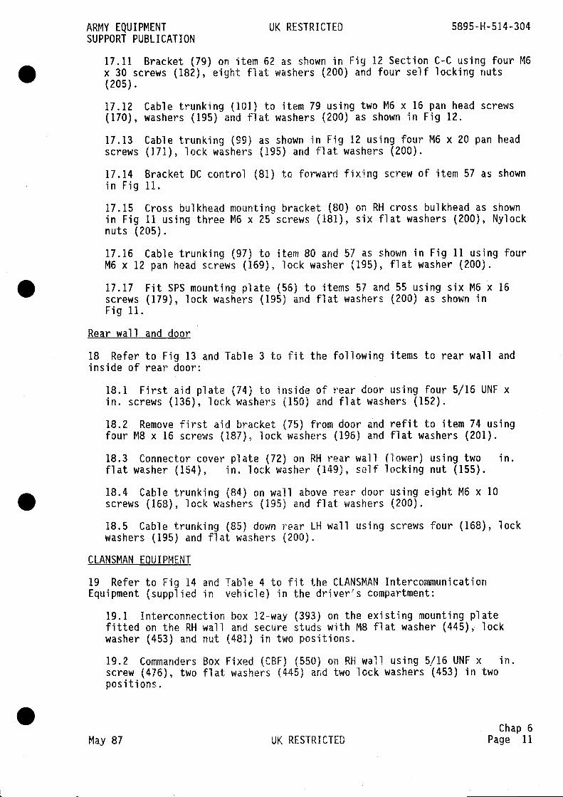
ARMY EQUIPMENT UK RESTRICTED 5895-H-514-304SUPPORT PUBLICATION
17.11 Bracket (79) on item 62 as shown in Fig 12 Section C-C using four M6x 30 screws (182), eight flat washers (200) and four self locking nuts(205).
17.12 Cable trunking (101) to item 79 using two M6 x 16 pan head screws(170), washers (195) and flat washers (200) as shown in Fig 12.
17.13 Cable trunking (99) as shown in Fig 12 using four M6 x 20 pan headscrews (171), lock washers (195) and flat washers (200).
17.14 Bracket DC control (81) to forward fixing screw of item 57 as shownin Fig 11.
17.15 Cross bulkhead mounting bracket (80) on RH cross bulkhead as shownin Fig 11 using three M6 x 25 screws (181), six flat washers (200), Nylocknuts (205).
17.16 Cable trunking (97) to item 80 and 57 as shown in Fig 11 using fourM6 x 12 pan head screws (169), lock washer (195), flat washer (200).
17.17 Fit SPS mounting plate (56) to items 57 and 55 using six M6 x 16screws (179), lock washers (195) and flat washers (200) as shown inFig 11.
Rear wall and door
18 Refer to Fig 13 and Table 3 to fit the following items to rear wall andinside of rear door:
18.1 First aid plate (74) to inside of rear door using four 5/16 UNF xin. screws (136), lock washers (150) and flat washers (152).
18.2 Remove first aid bracket (75) from door and refit to item 74 usingfour MB x 16 screws (187), lock washers (196) and flat washers (201).
18.3 Connector cover plate (72) on RH rear wail (lower) using two in.flat washer (154), in. lock washer (149), self locking nut (155).
18.4 Cable trunking (84) on wail above rear door using eight M6 x 10screws (168), lock washers (195) and flat washers (200).
18.5 Cable trunking (85) down rear LH wall using screws four (168), lockwashers (195) and flat washers (200).
CLANSMAN EQUIPMENT
19 Refer to Fig 14 and Table 4 to fit the CLANSMAN IntercommunicationEquipment (supplied in vehicle) in the driver's compartment:
19.1 Interconnection box 12-way (393) on the existing mounting platefitted on the RH wail and secure studs with MB flat washer (445), lockwasher (453) and nut (481) in two positions.
19.2 Commanders Box Fixed (CBF) (550) on RH wall using 5/16 UNF x in.screw (476), two flat washers (445) and two lock washers (453) in twopositions.
Chap 6May 87 UK RESTRICTED Page 11
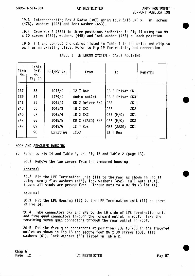
5895-H-514-304 UK RESTRICTED ARMY EQUIPMENTSUPPORT PUBLICATION
19.3 Interconnecting Box 3 Radio (387) using four 5/16 UNF x in. screws(476), washers (445) and lock washer (453).
19.4 Crew Box 2 (385) in three positions indicated in Fig 14 using two M8x 20 screws (439), washers (445) and lock washer (453) at each position.
Fit and connect the cables listed in Table 1 to the units and clip tousing existing clips. Refer to Fig 19 for routeing and connection.
ROOF AND ARMOURED HOUSING
TABLE 1 INTERCOM SYSTEM - CABLE ROUTEING
.
20 Refer to Fig 14 and Table 4, and Fig 15 and Table 2 (page 13).
20.1 Remove the two covers from the armoured housing.
Internal
20.2 Fit the LPE Termination unit (11) to the roof as shown in Fig 14using twenty flat washers (446), lock washers (452), full nuts (464).Ensure all studs are grease free. Torque nuts to 4.07 Nm (3 lbf ft).
External
20.3 Fit the LPE Housing (13) to the LPE Termination unit (11) as shownin Fig 14.
20.4 Take connectors SK7 and SK8 to the LH side of LPE Termination unitand five quad connectors through the forward outlet in roof. Take theremaining seven quad connectors through the rear outlet in roof.
.
20.5 Fit the fiveoutlet as shown inwashers (61), lock
quad connectors at positions 7Q7 to 7Q5 in the armouredFig 15 and secure four M6 x 30 screws (58), flatwashers (62) listed in Table 2.
Chap 6Page 12 UK RESTRICTED May 87
19.5wall
.
ItemNo.
CableRef.No.
Fig 20
HHI/MV No. From To Remarks
237
289
241
243
245
247
249
83
84
85
86
87
88
89
90
1045/1
1179/1
1045/2
1045/3
1045/4
1045/5
1045/6
Existing
12 T Box
Audio outletCB 2 Driver SK2
lB 3 SKilB 3 SK2
CB 2 (SASO) SK2
12 T Box
ICJB
CB 2 Driver SKiCB 2 Driver SK3
CBF SKi
CBF 5K2
CB2 (M/C) SKi
CB2 (M/C) SK2
CB2 (SASO) SKi
12 T Box
.

ARMY EQUIPMENT UK RESTRICTED 5895-H-514-304SUPPORT PUBLICATION
20.6 Clamp the five cable assemblies together using two clamps (30)secured to bosses on roof with two M8 x 25 screws (75), plain washers(79), lock washers (80) in two positions as shown in Fig 15 and listed inTable 2.
20.7 Fit and secure the seven connectors to positions 7Q4 to H/FQ inarmoured housing using four M6 x 39 screws (58), flat washers (61) andlock washers (62).
Note
At positions SUB7Q1 to 7Q8 and H/FQ orientate the yellow right mark asshown in Fig 15.
20.8 Clamp the seven cable assemblies to roof in two positions as shownin Fig 15 using two clamps (29), secured with M8 x 25 screws (75), plainwashers (79) lock washers (80). The fixings are listed in Table 2.
TABLE 2 ITEMS LIST, CLAMP ASSEMBLIES (Fig 15)
ItemNo.
NSN/FV No. Item Qty Remarks
19 FV 2048730 Lights conduit assy 1
20 FV 2048731 7 quad conduit assy 1
29 FV 2048381 Clamp assembly 2
30 FV 2048458 Clamp assembly 2 All these itemsin the externalequipment packFV 2047934
are
58 5305-99-122-5363 Screw, Hex Hd,M6 x 30
56
61 5310-99-122-6474 Washer, flat M6 56
62 5310-99-137-9232 Washer, lock singlecoil M6
56
75 5305-99-122-5367 Screw, Hex Hd M8 x 25 4
79 5310-99-122-6475 Washer, plain M8 4
80 5310-99-138-9227 Washer, lock singlecoil M8
4
20.9 Refit the two covers on the armoured housing.
Internal
20.10 Penthouse lights (397) in four positions on roof as shown in Fig 15.Fit using existing fixings and two internal teeth shakeprooF washers (457)at earth lead fixing.
Chap 6May 87 UK RESTRICTED Page 13

5895-H-514-304 UK RESTRICTED ARMY EQUIPMENTSUPPORT PUBLICATION
20.11 At No. 1 position fit lead electrical (323).
20.12 At No. 2 position fit lead electrical (325). S20.13 At No. 3 position fit lead electrical (327).
20.14 At No. 4 position fit lead electrical (329).
20.15 Secure each lead electrical to light casing using existing screw,and to boss in roof using two internal teeth shakeproof washers (457), andscrew (470) where single leads are fitted and three washers (457) or (439)where another lead uses the same fixing.
20.16 Unit Fire Suppression Remote (19) to bracket on roof, RH sideforward, (Fig 14, Sect D-D) using M8 x 45 screws (440), two flat washers(445), one lock washer (453), nut (465) and three internal teeth shakeproofwashers (447) on the other screw (440), flat washer (445) and nut (465).
Note
Remove and retain the spacer supplied with this unit for use later. 520.17 Fit lead electrical (265) from APU Interface unit to boss in roofused for lead electrical (329) and secure together with M8 x 20 screw(439), three internal teeth shakeproof washers (459).
20.18 Fit unit Civil LPE to internal roof LH forward position, asindicated in Fig 14, as follows:
20.18.1 Remove the two lock nuts from the connector on top of unit.
20.18.2 Remove bag containing one gasket.
20.18.3 Position the unit with identification plate facing to centreof vehicle, take cables through hole in roof.
20.18.4 Secure unit (5) to roof using two M6 x 12 screws (431), lockwasher (452), flat washer (444).
External 520.19 On the outside of vehicle:
20.19.1 Remove gasket from bag and fit gasket over cables from unitCivil LPE.
20.19.2 Fit conduit over cables and secure knurled lock ring to unitconnector.
20.19.3 Fit and secure the 7-quad conduit assembly (20) Fig 15, in thearmoured housing at Civil Loops 7Q8 position using M6 x 30 screws(58), flat washer (61), lock washer (62) in four positions. Itemslisted in Table 2.
Chap 6Page 14 UK RESTRICTED May 87
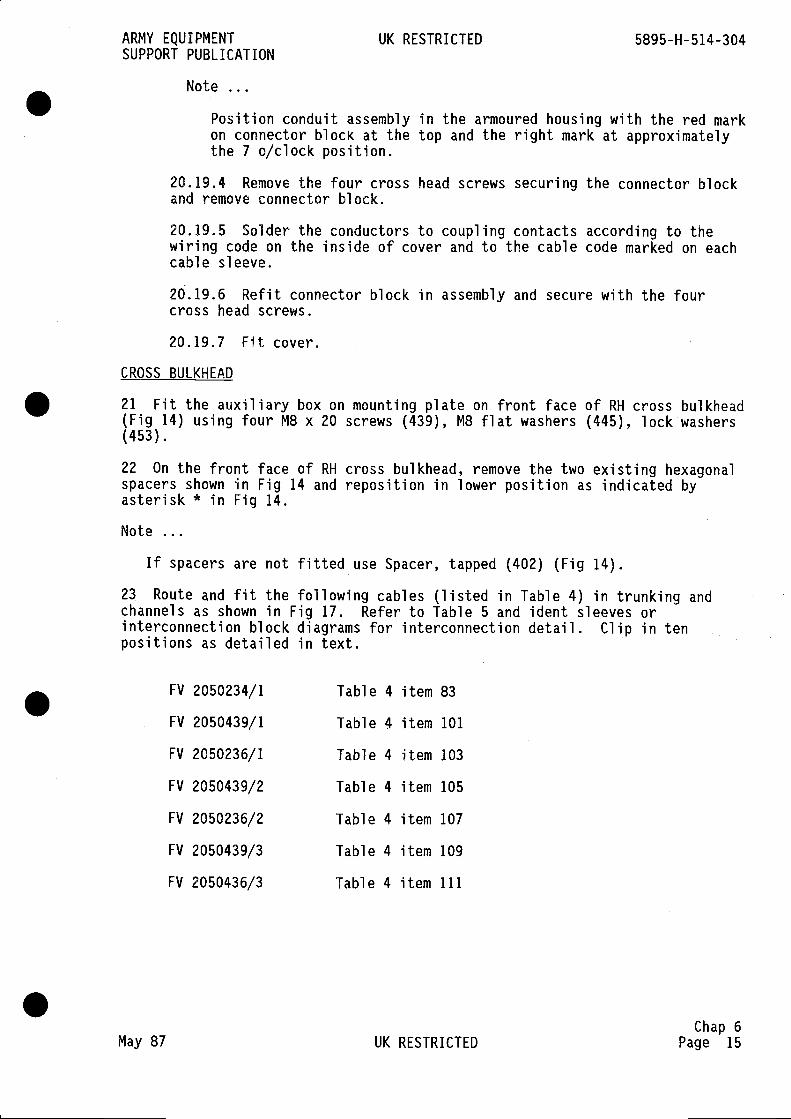
ARMY EQUIPMENT UK RESTRICTED 5895-H-514-304SUPPORT PUBLICATION
Note
Position conduit assembly in the armoured housing with the red markon connector block at the top and the right mark at approximatelythe 7 0/clock position.
20.19.4 Remove the four cross head screws securing the connector blockand remove connector block.
20,19.5 Solder the conductors to coupling contacts according to thewiring code on the inside of cover and to the cable code marked on eachcable sleeve.
20.19.6 Refit connector block in assembly and secure with the fourcross head screws.
20.19.7 Fit cover.
CROSS BULKHEAD
21 Fit the auxiliary box on mounting plate on front face of RH cross bulkhead(Fig 14) using four M8 x 20 screws (439), MB flat washers (445), lock washers(453).
22 On the front face of RH cross bulkhead, remove the two existing hexagonalspacers shown in Fig 14 and reposition in lower position as indicated byasterisk * in Fig 14.
Note
If spacers are not fitted use Spacer, tapped (402) (Fig 14).
23 Route and fit the following cables (listed in Table 4) in trunking andchannels as shown in Fig 17. Refer to Table 5 and ident sleeves orinterconnection block diagrams for interconnection detail. Clip in tenpositions as detailed in text.
FV 2050234/1 Table 4 item 83
FV 2050439/1 Table 4 item 101
FV 2050236/1 Table 4 item 103
FV 2050439/2 Table 4 item 105
FV 2050236/2 Table 4 item 107
FV 2050439/3 Table 4 item 109
FV 2050436/3 Table 4 item 111
Chap 6May 87 UK RESTRICTED Page 15
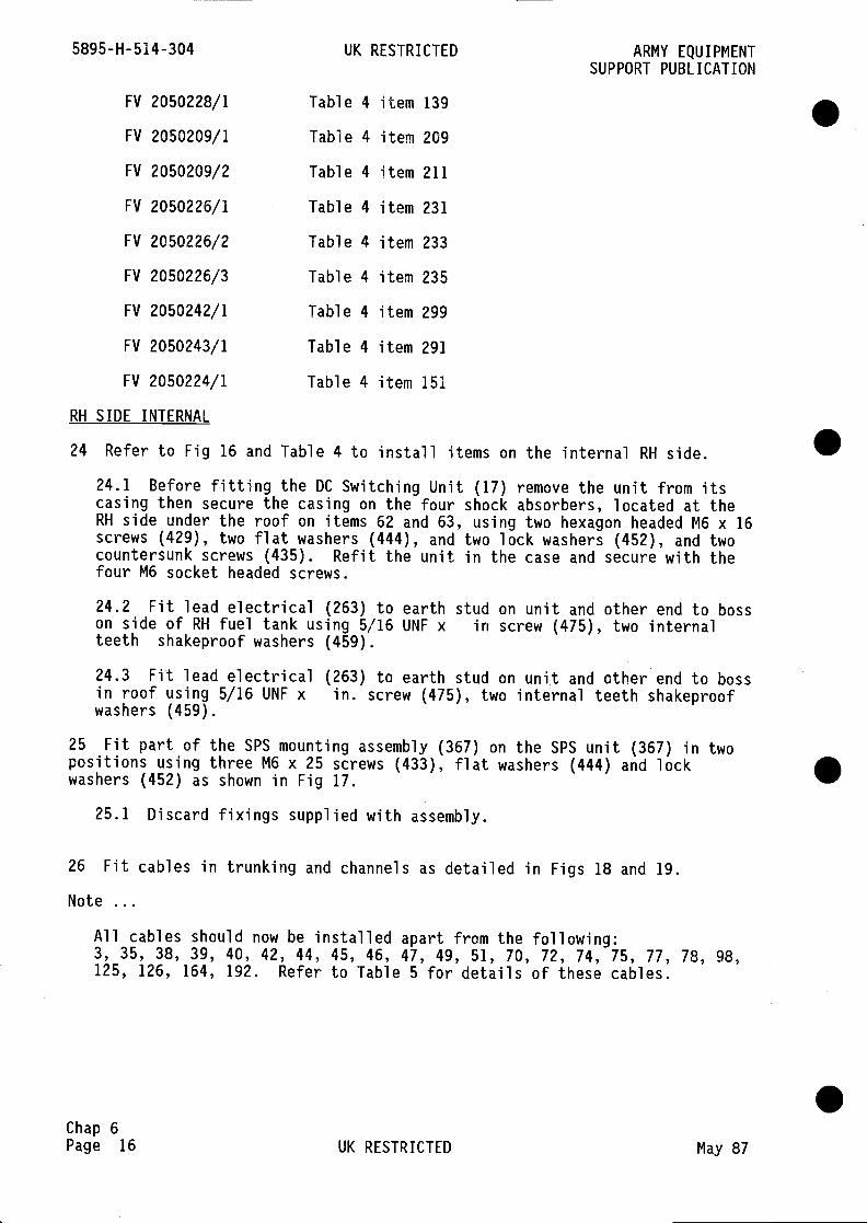
5895-H-514-304 UK RESTRICTED ARMY EQUIPMENTSUPPORT PUBLICATION
FV 2050228/1 Table 4 item 139
FV 2050209/1 Table 4 item 209
FV 2050209/2 Table 4 item 211
FV 2050226/1 Table 4 item 231
FV 2050226/2 Table 4 item 233
FV 2050226/3 Table 4 item 235
FV 2050242/1 Table 4 item 299
FV 2050243/1 Table 4 item 291
FV 2050224/1 Table 4 item 151
RH SIDE INTERNAL
24 Refer to Fig 16 and Table 4 to install items on the internal RH side. S24.1 Before fitting the DC Switching Unit (17) remove the unit from itscasing then secure the casing on the four shock absorbers, located at theRH side under the roof on items 62 and 63, using two hexagon headed M6 x 16screws (429), two flat washers (444), and two lock washers (452), and twocountersunk screws (435). Refit the unit in the case and secure with thefour M6 socket headed screws.
24.2 Fit lead electrical (263) to earth stud on unit and other end to bosson side of RH fuel tank using 5/16 UNF x in screw (475), two internalteeth shakeproof washers (459).
24.3 Fit lead electrical (263) to earth stud on unit and other end to bossin roof using 5/16 UNF x in. screw (475), two internal teeth shakeproofwashers (459).
25 Fit part of the SPS mounting assembly (367) on the SPS unit (367) in twopositions using three M6 x 25 screws (433), flat washers (444) and lockwashers (452) as shown in Fig 17.
25.1 Discard fixings supplied with assembly.
26 Fit cables in trunking and channels as detailed in Figs 18 and 19.
Note
All cables should now be installed apart from the following:3, 35, 38, 39, 40, 42, 44, 45, 46, 47, 49, 51, 70, 72, 74, 75, 77, 78, 98,125, 126, 164, 192. Refer to Table 5 for details of these cables.
.Chap 6Page 16 UK RESTRICTED May 87

ARMY EQUIPMENT UK RESTRICTED 5895-H-514-304SUPPORT PUBLICATION
CABLE TRUNKING COVERS
27 Fit cable covers and attach grommet strip (417) using adhesive (410) onedges of trunking and covers where cables enter and exit:
Fig 8 Item 51Fig 7 Item 53
Item 69, secure with six M8 x 16 screws (438), lock washers (453), flatwashers (445).
Fig 10 Item 59 Fig 21 Item 43Item 61 Item 75Item 71 Fig 12 Item 45
Fig 17 Item 31 Item 47Item 33 Item 49Item 57 Item 63
Fig 16 Item 35 Item 65
PIARMIGAN EQUIPMENT
Note
The LDA Multiplexer (515) is supplied with mounting tray PT 5562-1-601036.The mounting tray is surplus to requirements and should be returned tostores.
28 Fit the LDA Multiplexer (LDA MUX) (515) on the mounting tray and locatewith lugs and pins. Secure with the two clamps as shown in Fig 8.28.1 Connect lead electrical (87) to earth stud on LDA MUX using existingfixings and other end to stud on bulkhead using 5/16 UNF x in. screw(475), three M8 internal teeth shakeproof washers (459).
28.2 Connect cables to LDA MUX unit as shown in Fig 22 and listed inTable 5.
29 Refer to Fig 10 and Table 4 to fit the Central Alarm Panel (9) on thecross bulkhead and proceed as follows:
29.1 Fit lead electrical (219.) to boss on roof using 5/16 UNF x in screw(475), two internal teeth shakeproof washers (459).
29.2 Fit cable clips (351) (1 off), (352) (2 off) on cable assembly HHI/MV1039/1 and fit clips to underside of Central Alarm Panel (9) as shown inFig 10 using M4 flat washer (450), M4 lock washer (442) and M4 nut (462).29.3 Fit the Central Alarm Panel (9) on the two brackets of the ULSmounting frame as shown in Fig 10 and secure with four M6 x 16 screws(429), flat washers (444), lock washers (452) in two positions on eachbracket.
29.4 Fit other end of lead electrical (219) to earth terminal at rear ofCentral Al arm Panel.
29.5 Connect cables to Central Alarm Panel as shown in Fig 22 and listedin Table 5.
Chap 6May 87 UK RESTRICTED Page 17
5895-H-514-304 UK RESTRICTED ARMY EQUIPMENTSUPPORT PUBLICATION
30 Connect the following cables and leads electrical: 87 (3), 219 (72), 215(70), 317 (192).
Note
The numbers in brackets refer to Table 5 and interconnection block diagramsFigs 20 and 21.
31 Fit Unit Control and Distribution (15) on its mounting assembly on RH sidewall, forward, as shown in Fig 17, using MB x 16 screws (438), flat washers(445), lock washers (453), in two positions.
31.1 Fit lead electrical (317) under top LH M3 x 16 screw (438) as shown,using two internal teeth shakeproof washers (459).
32 Fit other end of lead electrical (317) on earth terminal of Unit Controland Distribution together with lead electrical (215) using three internalteeth shakeproof washers.
33 Connect cables to Unit Control and Distribution as shown in Fig 22 andlisted in Table 5.
34 Refer to Figs 4 and 13 and Table 3 to fit the following items to the roofinternal:
34.1 Mounting Frame, Data Adaptor (73) to roof at rear RH position usingsix 5/16 UNF x 5/8 screws (135), lock washers (196), flat washers (201).
34.2 Support bracket (83) to roof at rear LH position using six 5/16 UNF x5/B screws (135), lock washers (150), flat washer (152),
34.3 Two shock mounts (115) on mounting frame, Data Adaptor (73) as shownin Fig 13 and secure using four M5 x 16 screws (167), eight plain washers(213), four Nylock nuts (212) in two positions.
REAR BULKHEAD
35 Refer to Fig 23 and Table 4 to fit the following items on rear bulkhead:
35.1 Fit coupling nut (488), washer (490), sealing cone (492) on cable(229) as shown on Fig 18.
35.2 Remove cover plate from security light and connect both wires toterminal block. Refit cover plate.
35.3 Security light (349) using two M4 x 20 screws (421), lock washer(450), flat washers (442). Mark: SECURITY LIGHT No.2 on the mountingplate under the light using ink white (414), catalyst (415), thinners (416)as shown on Fig 14.
35.4 Secure lead electrical (321) to boss in roof above unit FireSuppression Control (28) and secure using two shakeproof washers (459) withexisting screw. Discard other washers.
35.5 Secure Unit Fire Suppression Control (28) using M6 x 16 screws (429),washers (444) and (452) on the two shock mounts. .
Chap 6Page 18 UK RESTRICTED May 87

ARMY EQUIPMENT UK RESTRICTED 5895-H--514—304SUPPORT PUBLICATION
35.6 Mounting Assembly, (Data Adaptor and Static Sub Set) (357) (ChassisElectrical Equipment) on the mounting, on upper rear RH wall, using MS x 35screws (425), eight flat washers (443), self lock nuts (467).
Note
Ensure all four shock mounts are fitted with the large washer underneathas shown in Fig 1.
35.7 Data Adaptor (528). Remove Mounting Tray PT 5562-1-601022 and returnto stores as surplus to requirements.
35.8 Fit the Data Adaptor (528) on the Mounting Assembly (357) and securewith clamp.
30 1REE
DATA ADAPTORI j
STATIC SUBSET WASHER
Fig 1 Data Adaptor and static sub set shock mounts
35.9 Fit plate electric shock (405) on inside of rear door using six M4 x10 pan head screws (419), lock washers (449) flat washers (441).
35.10 Fit lead electrical (161) to same boss in roof as lead electrical(327) from No. 3 Penthouse light and secure with shakeproof washers.
35.11 Fit other end of lead electrical (161) to earth terminal on the dataadaptor A (528).
TRANSOM
36 Refer to Fig 10 and Table 4 to fit the following items on cross bulkhead:
36.1 Assemble bracket (496), rod (494) and curtain (498). Using M6 x 16screw (429), washer flat M6 (444) and lock washer M6 (452) in twopositions.
36.2 Fit coupling nut (488), washer (490), sealing cone (492) on cables(229) and (213).
36.3 Remove cover plate from security light and connect both cables.Refit cover plate.
Chap 6May 87 UK RESTRICTED Page 19

5895-H-514-304 UK RESTRICTED ARMY EQUIPMENTSUPPORT PUBLICATION
36.4 Security light (349) above transom using two M4 x 20 screws (421),flat washers (442), lock washers (450).
36.5 Using items (414), (415), (416), write as shown in Fig 8 'SECURITYLIGHT No. 1' on mounting plate under the security light.36.6 Secure lead electrical (215) (hanging loose on Unit Control andDistribution) to security light No. 1 mounting plate as shown in Fig 10 and36.1 above.
36.7 Remove the existing fire warning light above the transom and refitcomplete with bracket rod and curtain assembly as detailed in Fig 10 and36.1 above.
37 Temporarily fit the Secondary Packet Switch (SPS) (367) to adjust heightof rear shock mount with bracket on wall as shown on Fig 17.
38 Fit the two SPS support rods (60) (Fig 9) on the floor. Adjust height ofrod, with adjuster on each rod, to clear the SPS unit (using two M6 x 16screws (179) washers lock (195) and washers (200) in two positions.
38.1 Remove SPS unit from vehicle for refit later.
39 Refer to Fig 11, Table 3 to fit the SPS mounting assembly on the RH sideand proceed as follows:
39.1 Remove the mounting tray from the SEOW unit (361) and retain the fourscrews.
39.2 Remove the four shock mounts from SEOW mounting tray.
40 Fit the four SEOW shock mounts on the SEOW mounting on table (59) (Fig 11)as follows:
40.1 Position and secure two shock mounts on RH side of mounting asshown in Fig 9 using four M4 x 16 countersunk screws (159), four flatwashers (199), four lock washers (194) and Nyloc nut (206) in the two LHpositions of the two shockmounts, and four M4 x 12 countersunk screws(160), and washer as detailed above in the RH position.
40.2 On the RH side of mounting secure the two shockmounts using four M4 x16 hexagon head screws (163), four flat washers (199), four lock washers(194) and four Nyloc nuts (206) in RH positions on the two shock mounts,and four M4 x 12 screws (162) and washers (194), (199) and nut (206) in theLH positions.
41 Fit table top (59) to mounting plate (55) on the RH side using spacers(61) and M6 x 45 bolts (183), lock washers (195), flat washers (200) as shownin Fig 11, Section G-G.
42 Refer to Fig 17 and Table 4 to fit the following items on RH side,internal:
42.1 Guard (413) using existing fixings on the Unit Control andDistribution mounting. .
Chap 6Page 20 UK RESTRICTED May 87
ARMY EQUIPMENT UK RESTRICTED 5895-H-514-304SUPPORT PUBLICATION
42.2 Fire extinguisher bracket (391) (2 off) on guard (413) and using M4 x16 countersunk screws (423) and M4 x 12 countersunk screw (436) as shown inFig 17.
42.3 Fit fire extinguishers (389) in each bracket.
Secondary Packet Switch Unit (SPS1
43 Fit the SPS unit (357) on RH floor as follows:
Note
A fork lift and at least two men are required to handle this unit.
43.1 Fit two mounting bars, supplied with unit, on underside of unit usingthree M6 x 25 screws (433), flat washers (444) and lock washers (452).Discard fixings supplied with unit.
43.2 Fit lead electrical (221) to SPS unit using M6 x 25 screw (433), twointernal teeth shakeproof washers (458) as shown in Fig 17.
43.3 Place the SPS unit on the mid RH floor and align the four holes inshock mounts with slots in the bracket on the RH wall and with the fourholes in four positions on the floor.
43.4 Loosely secure the rear shock mount to the wall plate bracket usingfour M5 x 25 screws (422), lock washer (450), eight flat washers (442) andfull nuts (462) in two positions.
43.5 Secure unit to floor using four screws (422), washers (442) and (450)in four positions.
43.6 Tighten the rear shock mount fixings.
43.7 At rear of table use round spacer to secure SPS cables with tie wrap(411).
43.8 Secure loose end of lead electrical (221) to boss on wall using UNF
x screw (473), two shakeproof washers (459) as shown in Fig 17.
43.9 Fit the SPS control unit, supplied with SPS unit (367), on top oftable as shown in Fig 17 using four M6 x 25 screws (433), flat washers(444) and lock washers (452).
43.9.1 Fit cable clip (418) on cable at rear of unit and secure clip onbracket to the table using MS x 16 screw (428), two flat washers (443),lock washer (451) and nut (463).
43.9.2 Connect the cable to PL 1 on SEOW.
Static Sub Set
44 Fit the static Sub Set (536) on the table (RH side) as shown in Fig 17 asfollows:
44.1 Remove the Chassis Electrical Equipment (357) from the pack and checkthat the large washers on each shock mount are as shown in Fig 1. If notreposition washers correctly.
Chap 6
May 87 UK RESTRICTED Page 21
5895-H-514-304 UK RESTRICTED ARMYEQUIPMENTSUPPORT PUBLICATION
44.2 Fit Chassis Electrical Equipment on the mounting bracket on thetable (Fig 17) ensuring that clamp is at the front. Secure using fourM5 x 35 screws (425), eight flat washer (443), nut (467).
45 Take the Static Sub Set (536) from pack. Remove mounting tray PT 5562-1-601022 and return tray to stores as surplus to requirements.
45.1 Fit the Static Sub Set on the Chassis Electrical Equipment and securewith clamp.
45.2 Fit and secure lead electrical (223) to boss in roof above staticsub set using 2BA x in. screw (470) and two internal teeth shakeproofwashers (457) as shown in Fig 17.
45 3 Fit other end of lead to earth terminal on static sub set.
Single Engineering Order Wire Unit (SEOW)
46 Refer to Fig 17 and Table 4 to fit the SEOW unit (361) as follows:
46.1 Fit and secure the SEOW unit (361) on the mounting tray as shown inFig 17 and secure with the two clamps at front.
46.2 Fit lead electrical (147) to earth connector on SEOW and take leadunderneath the unit and up to boss in roof. Secure to boss with M6 x 160screw (429), two internal teeth shakeproof washers (458), two flat washers(444), lock washers (452).
Seat
47 Fit the seat mounting assembly (27) on the LH forward floor as shown inFig 6 using four M10 x 16 screws (192), lock washers (197), flat washers(202).
48 Fit seat (339) as shown in Fig 7 using four MB flat washers (445), lockwashers (453), M8 nuts (465). Fit seat belt (335) to the two loops on LH sideof seat and the two loops on LH sill.
Teleprinter, FAX PSU mounting assemblies
49 Refer to Fig 5 and Table 3 and fit the following items:
49.1 Mounting bars (125) in two positions on the rear LH floor using fourM4 x 25 screws (165), lock washers (194), flat washers (199) in twopositions.
49.2 Teleprinter mounting frame and stowage assembly LH (25), floor, LHside, using seven M8 x 20 screws (188), lock washers (196), flat washers(201).
49.3 Fit padlock through hole in stowage door.
49.4 FAX PSU Mounting Tray (19) on the two mounting bars (125) and securewith mounting plates (16), and (17) on the two bars using two M8 x 20countersunk screws (184) as shown in Fig 5.
.Chap 6Page 22 UK RESTRICTED May 87

ARMY EQUIPMENT UK RESTRICTED 5895-H-514-304SUPPORT PUBLICATION
50 Refer to Fig 8 and Table 4 to install the following items on LH
50.1 Tray assembly teleprinter (371) on the mounting frame and secureusing eight M5 x 16 screws (428), sixteen flat washers (443), eight nuts(467).
50.2 Fit and secure teleprinter (369) an mounting tray.
50.3 Mounting Assembly Data Adaptor and static sub set (357) (ChassisElectrical Equipment) on the mounting bracket on LH teleprinter mountingassembly and secure using four M5 x 35 screws (425), eight flat washers(443) and self lock nuts (467). Ensure the flat washer on each shock mountis fitted as shown in Fig 1.
50.3.1 Return mounting tray supplies in pack with item 528 to stores assurplus.
50.4 Fit the Data Adaptor on the chassis electrical equipment and securewith clamp.
50.5 Secure lead electrical (175) and (273) to floor at LH roof of FAX PSUframe using existing screw and three shakeproof washers (459) as shown inFig 8. Discard existing washers.
50.5.1 Connect other end of lead electrical (175) to the Data Adaptoras shown in Fig 8.
50.5.2 Connect other end of lead electrical (273) to static sub setearth terminal as shown in Fig 8.
FAX PSU
50.6 FAX PSU (399). Remove clamping angle before fitting.
50 6 1 Fit FAX PSU (399) on mounting tray
50.6.2 Refit clamping angle.
50.6.3 Fit lead electrical (227) and (179) on teleprinter mountingframe as shown in Fig 8 using UNF in. screw (472) and three internalteeth shakeproof washers (458).
50.6.4 Connect other end of lead (227) to FAX PSU earth terminal.
50.6.5 Connect other end of lead (179) to teleprinter as shown inFig 8.
50.7 Fit cable clips (406) and (408) over cables from patch panel as shownin Fig 8 using existing fixings.
to to install the following items on RH siderear:
51.1 Stowage box assembly (28) using four M16 x 16 screws (190), lockwashers (197), flat washers (202).
Chap 6May 87 UK RESTRICTED Page 23

5895-H-514-304 UK RESTRICTED ARMY EQUIPMENTSUPPORT PUBLICATION
51.2 Teleprinter mounting frame and stowage assembly RH (67) using fourM1O x 20 screws (190), lock washers (197), flat washers (202).
Seat and Teleprinter tray
52 Refer to Figs 16 and 22 to fit the following items at rear RH position:
52.1 Seat (339) to stowage box assembly using four M8 flat washers (445)four lock washers (453), four M8 (465) nuts on existing M8 screws.
52.2 Seat belt (335) to loops on RH sill.
52.3 Tray Assembly Teleprinter (371) on mounting frame using four M4 x 35countersunk screws (424), four flat washers (442), four lock washers (450),M4 full nuts (462) in four positions.
52.4 Fit and secure teleprinter (369) on the mounting tray.
52.5 Fit lead electrical (165) to boss on rear RH wall using existingscrew and two shakeproof washers (458). Discard existing washers. Fitother end on teleprinter as above.
Notes
(1) Stow Telex paper (401) in locker.
(2) To avoid damage to typewriter printing head the paper must be put intypewriter before testing.
53 Refer to Fig 23 and Table 4 to install the following items at the rear RHposition:
53.1 Unit Teleprinter Alarm (23) on plate above teleprinter table using M8x 35 screw (446), two shakeproof washers (459) and spacer M8 x x in. onRH side, see Fig 23. Use screw (446), lock washer (453), flat washer (445)on LH side. Fit spacer as shown in Fig 2.
Note
The spacer is supplied with the Fire Suppression Control Unit (Table 4item 28) or with items having Muffelite shock mounts and are surplus torequirements.
53.2 Mounting Assembly Data Adaptor and static sub set (357) (ChassisElectrical Equipment) as previously detailed in Sub Para 35.4.
53.3 Static sub set on Chassis Electrical Equipment.
53.4 Lead electrical (271) to earth terminal on static sub set. Other endto boss on fuel tank bulkhead using existing M1O screw. Discard existingwashers and fit two M1O shakeproof washers (460).
.Chap 6Page 24 UK RESTRICTED May 87
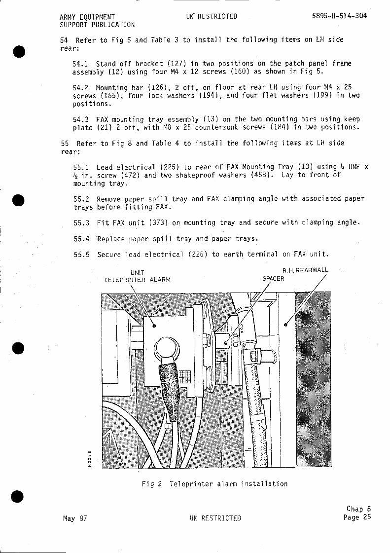
ARMY EQUIPMENT RESTRICTED 5895—H-514—304SUPPORT PUBLICATION
54 Refer to Fig 5 and Table 3 to install the following items on LH siderear:
54.1 Stand off bracket (127) in two positions on the patch panel frameassembly (12) using four M4 x 12 screws (160) as shown in Fig 5.
54.2 Mounting bar (126), 2 off, on floor at rear LH using four M4 x 25screws (165), four lock washers (194), and four flat washers (199) in twopositions.
54.3 FAX mounting tray assembly (13) on the two mounting bars using keepplate (21) 2 off, with M8 x 25 countersunk screws (184) in two positions.
55 Refer to Fig 8 and Table 4 to install the following items at LH siderear:
55.1 Lead electrical (225) to rear of FAX Mounting Tray (13) using ¼ UNF x½ in. screw (472) and two shakeproof washers (458). Lay to front ofmounting tray.
55.2 Remove paper spill tray and FAX clamping angle with associated papertrays before fitting FAX.
55.3 Fit FAX unit (373) on mounting tray and secure with clamping angle.
55.4 Replace paper spill tray and paper trays.
55.5 Secure lead electrical (225) to earth terminal on FAX unit.
UNITTELEPRINTER ALARM
Fig 2 Teleprinter alarm installation
Chap 6May 87 UK RESTRICTED Page 25

5895-H-514-304 UK RESTRICTED ARMY EQUIPMENTSUPPORT PUBLICATION
56 Connect all loose cables and leads electrical as shown in Figs 20, 21 and22.
57 Fit the following cables: 155 (39), 157 (40), 167 (45), 171 (47). Forbracketed numbers refer to Table 5.
58 Refer to Fig 5 and Table 3 to install the following items in the FAXassembly:
58.1 Screw assembly, FAX clamping (15) using flat washer (201), lockwasher (196), nut (207), two to clamp FAX and two to clamp FAX PSU.
58.2 Clamping angle (20).
58.3 FAX spill tray (23).
58.4 Clamping angle assembly (14).
58.5 Paper tray assembly (22).
58.6 Thumb screws (18) in two positions.
BATTERIES AND BATTERY VENTING ASSEMBLIES
Fit battery vent pipe (503) to flame trap and route and clip along forwardwall as shown in Fig 24.
59.1 Connect Tee piece (345) to pipe (503) and to pipe (484).
59.2 Clip pipe (484) to wall using existing clip as shown in Fig 24.
Prepare and fit three sets of batteries (379) in the drivers compartmentshown in Fig 24 and detailed in following paragraphs:
NBC Batteries floor forward Dosition
61.1 Secure harness (305) to boss on LH wall of compartment using 3/8 UNFx in. screw (478) and two shakeproof washers (461).
61.2 Fit two batteries (379) in battery box No. 3 Mk 1 (381) and fit inbrackets on floor under driver's seat.
61.3 Fit positive (+ Ve) connector of harness (307) to positive (+ Ve)battery post on battery.
61.4 Fit negative (- Ve) connector of harness (307) to negative (- Ve)post on other battery.
61.5 Fit existing + Ve cable (FV 167668/4) to positive (+ Ve) batteryterminal post.
61.6 Fit cable (305) to negative (.- Ve) battery terminal post.
Chap 6Page 26 UK RESTRICTED May 87
59RH
60as
61
.
.
.

ARMY EQUIPMENT UK RESTRICTED 5895-H-514-304SUPPORT PUBLICATION
61.7 Fit battery venting assembly (29) to batteries.
61.8 Secure battery box to floor with clamp bar assembly (508).
61.9 Connect and route battery venting pipe (486) to tee piece and ventpipe (503) as shown in Fig 24,
Note
No cover is provided for the NBC batteries.
62 Communications
62.1 Fit and secure holding plate (347) on LH sill as shown in Fig 24using two 5/16 UNF x screws (476) and lock washers
62.2 Secure cable (201) to boss on RH wall, near cross bulkhead, using5/16 UNF x in. screw (476) and two shakeproof washers (447).
62.3 Fit two batteries (379) in battery box No, 3 Mk 1 (381).
62.4 Place battery box in holding plates on LH sill.
62.5 Fit the + Ve connector of harness (307) on one battery positive + Vepost.
62.6 Fit the - Ve connector of harness (307) on other battery negative -Ve post.
62.7 Connect cable (301) (running down RH wall) to battery + Ve terminal.
62.8 Secure cable (305) to boss on sill in front of battery using 3/8 UNFx in, screw (478) and two shakeproof washers (461).
62.9 Fit cable (305) to - Ve terminal post on other battery.
62.10 Fit battery venting assembly (29) to battery.
62.11 Fit and secure cover support bracket (22) using two UNF x in.screws (472), flat washers (482), lock washer.s (483) in two positions asshown in Fig 24.
62.12 Fit and secure cover support bracket (27) using two screws (472),flat washers (482), lock washers (483) in two positions as shown inFig 24.
Secure battery box to sill with clamp bar (25).
Fit battery box cover (506).
62.13
62.14
Chap 6May 87 UK RESTRICTED Page 27
5895-H-514-304 UK RESTRICTED ARMY EQUIPMENTSUPPORT PUBLICATION
63 APU Batteries, floor forward
63.1 Fit and secure frame mounting (502) to floor at position shown inFig 24 using five 3/8 UNF x in. screws (478) and lock washers (479).
63.2 Secure cable FV 167665/2 to forward LH fixing screw of frame mountingusing screw (478) and two shakeproof washers (461).
63.3 Place battery box No. 3 Mk 1 in the frame mounting.
63.4 Fit two batteries (379) in battery box No. 3 Mk 1.
63.5 Fit + Ve connector of existing harness (FV 167663/1) to + Ve terminalpost of one battery.
63,6 Fit - Ve connector to - Ve terminal post of other battery.
63.7 Fit + Ve connector of cable (303), running down RH wall, to + Veterminal post of other battery.
63.8 Fit battery venting assembly (29) on battery.
63.9 Secure battery box to floor with clamp bar (25).
63.10 Fit battery box cover (383).
63.11 Connect battery venting pipe (504) to item 29 on batteries.
63.12 Connect cable FV167665/2 to - Ve terminal post of battery.
LOOSE ITEMS
64 Stow the following items:
64.1 Stow screwdriver (4 mm), used on Patch Panel, in rear teleprinterdrawer.
64.2 Stow covers for ULS exchange and switchboard in the stowage box.
INSTALLATION CHECK-OUT AND TEST
65 Refer to Chap 7 for check-out and test procedures.
.Chap 6Page 28 UK RESTRICTED May 87
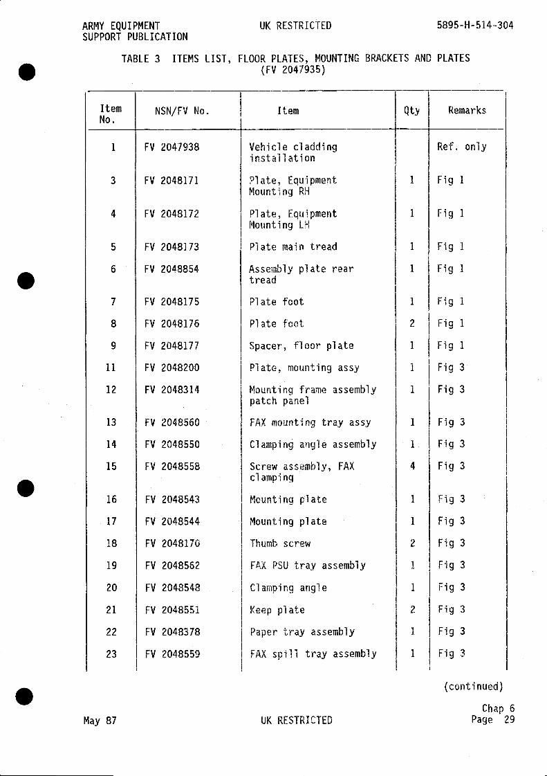
ARMY EQUIPMENT UK RESTRICTED 5895-H-514-304SUPPORT PUBLICATION
TABLE 3 ITEMS LIST, FLOOR PLATES, MOUNTING BRACKETS AND PLATES(FV 2047935)
[ternNo.
NSN/FV No. Item Qty Remarks
1 FV 2047938 Vehicle cladding Ref. onlyinstallation
3 FV 2048171 Plate, Equipment 1 Fig 1Mounting RH
4 FV 2048172 Plate, Equipment 1 Fig IMounting LH
5 FV 2048173 Plate main tread 1 Fig 1
6 FV 2048854 Assembly plate rear 1 Fig 1tread
7 FV 2048175 Plate foot 1 Fig 1
8 FV 2048176 Plate foot 2 Fig 1
9 FV 2048177 Spacer, floor plate 1 Fig 1
11 FV 2048200 Plate, mounting assy 1 Fig 3
12 FV 2048314 Mounting frame assembly I Fig 3patch panel
13 FV 2048560 FAX mounting tray assy 1 Fig 3
14 FV 2048550 Clamping angle assembly I Fig 3
15 FV 2048558 Screw assembly, FAX 4 Fig 3clamping
16 FV 2048543 Mounting plate 1 Fig 3
17 FV 2048544 Mounting plate 1 Fig 3
18 FV 2048170 Thumb screw 2 Fig 3
19 FV 2048562 FAX PSU tray assembly 1 Fig 3
20 FV 2048548 Clamping angle 1 Fig 3
21 FV 2048551 Keep plate 2 Fig 3
22 FV 2048378 Paper tray assembly 1 Fig 3
23 FV 2048559 FAX spill tray assembly 1 Fig 3
(continued)
Chap 6May 87 UK RESTRICTED Page 29
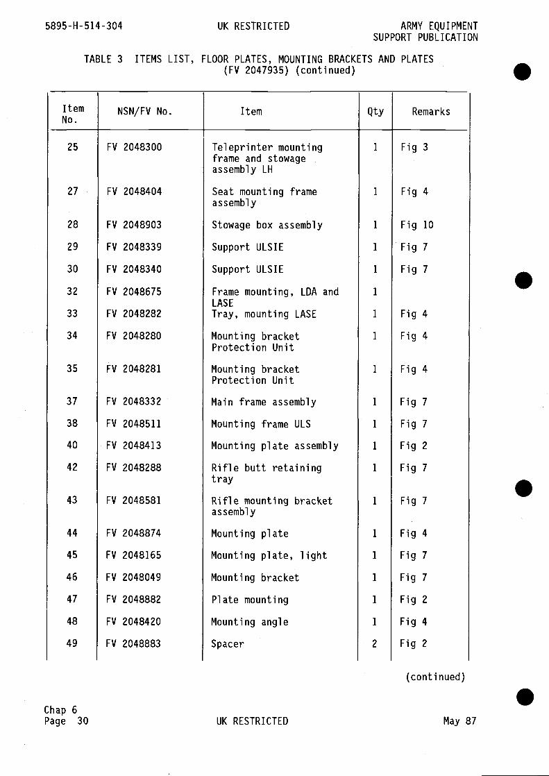
5895-H-514-304 UK RESTRICTED ARMY EQUIPMENTSUPPORT PUBLICATION
TABLE 3 ITEMS LIST, FLOOR PLATES, MOUNTING BRACKETS AND PLATES(FV 2047935) (continued)
ItemNo.
NSN/FV No. Item Qty Remarks
25 FV 2048300 Teleprinter mounting 1 Fig 3frame and stowageassembly LH
27 FV 2048404 Seat mounting frame 1 Fig 4assembly
28 FV 2048903 Stowage box assembly 1 Fig 10
29 FV 2048339 Support ULSIE 1 Fig 7
30 FV 2048340 Support ULSIE 1 Fig 7
32 FV 2048675 Frame mounting, LDA and 1
LAS E
33 FV 2048282 Tray, mounting LASE 1 Fig 4
34 FV 2048280 Mounting bracket 1 Fig 4Protection Unit
35 FV 2048281 Mounting bracket 1 Fig 4Protection Unit
37 FV 2048332 Main frame assembly 1 Fig 7
38 FV 2048511 Mounting frame ULS 1 Fig 7
40 FV 2048413 Mounting plate assembly 1 Fig 2
42 FV 2048288 Rifle butt retaining 1 Fig 7tray
43 FV 2048581 Rifle mounting bracket I Fig 7assembly
44 FV 2048874 Mounting plate 1 Fig 4
45 FV 2048165 Mounting plate, light 1 Fig 7
46 FV 2048049 Mounting bracket 1 Fig 7
47 FV 2048882 Plate mounting 1 Fig 2
48 FV 2048420 Mounting angle 1 Fig 4
49 FV 2048883 Spacer 2 Fig 2
(continued) .Chap 6Page 30 UK RESTRICTED May 87
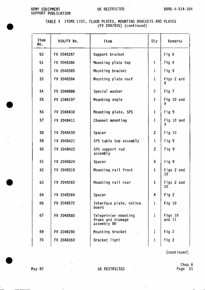
ARMY EQUIPMENT UK RESTRICTEDSUPPORT PUBLICATION
TABLE 3 ITEMS LIST, FLOOR PLATES, MOUNTING BRACKETS AND PLATES(FV 2047935) (continued)
ItemNo.
NSN/FV No. Item Qty Remarks
50 FV 2048387 Support bracket Fig 9
51 FV 2048386 Mounting plate top 1 Fig 9
52 FV 2048385 Mounting bracket 1 Fig 9
53 FV 2048384 Mounting plate roof 1 Figs 2 and9
54 FV 2048888 Special washer 2 Fig 7
55 FV 2048197 Mounting angle 1 Fig 10 and9
56 FV 2048430 Mounting plate, SPS 1 Fig 9
57 FV 2048411 Channel mounting 1 Fig 10 and9
58 FV 2048439 Spacer 2 Fig 10
59 FV 2048421 SPS table top assembly 1 Fig 9
60 FV 2048422 SPS support rod 2 Fig 9assembly
61 FV 2048824 Spacer 6 Fig 9
62 FV 2048319 Mounting rail front 1 Figs 2 and10
63 FV 2048265 Mounting rail rear 1 Figs 2 and10
64 FV 2048264 Spacer 4 Fig 2
66 FV 2048572 Interface plate, notice 1 Fig 10board
67 FV 2048580 Teleprinter mounting 1 Figs 10frame and stowage and 11assembly RH
69 FV 2048290 Mounting bracket 1 Fig 2
70 FV 2048269 Bracket light I Fig 2
(conti nued)
Chap 6May 87 UK RESTRICTED Page 31
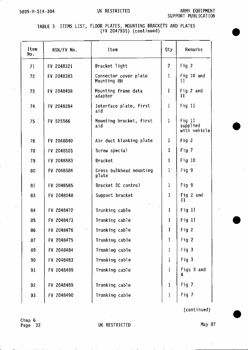
5895-H-514-304 UK RESTRICTED ARMY EQUIPMENTSUPPORT PUBLICATION
TABLE 3 ITEMS LIST, FLOOR PLATES, MOUNTING BRACKETS AND PLATES(FV 2047935) (continued)
ItemNo.
NSN/FV No. Item Qty Remarks
71 FV 2048321 Bracket light 2 Fig 2
72 FV 2048383 Connector cover plate 1 Fig 10 andMounting RH 11
73 FV 2048408 Mounting frame data 1 Fig 2 andadaptor 11
74 FV 2048284 Interface plate, first 1 Fig 11aid
75 FV 525566 Mounting bracket, first 1 Fig 11aid supplied
with vehicle
76 FV 2048840 Air duct blanking plate 1 Fig 2
78 FV 2048505 Screw special 3 Fig 7
79 FV 2048583 Bracket 1 Fig 10
80 FV 2048584 Cross bulkhead mounting 1 Fig 9plate
81 FV 2048585 Bracket DC control 1 Fig 9
83 FV 2048048 Support bracket 1 Fig 2 and11
84 FV 2048472 Trunking cable 1 Fig 11
85 FV 2048473 Trunking cable I Fig 11
86 FV 2048476 Trunking cable 1 Fig 2
87 FV 2048475 Trunking cable 1 Fig 2
89 FV 2048484 Trunking cable 1 Fig 3
90 FV 2048483 Trunking cable 1 Fig 3
91 FV 2048499 Trunking cable 1 Figs 3 and4
92 FV 2048489 Trunking cable 1 Fig 7
93 FV 2048490 Trunking cable 1 Fig 7
(conti nued)
Chap 6Page 32 UK RESTRICTED May 87
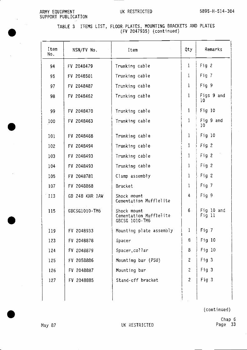
94
95
97
98
99
•100
101
102
103
104
105
107
113
115
119
123
124
125
126
127
FV 2048479
FV 2048501
FV 2048487
FV 2048462
FV 2048470
FV 2048463
FV 2048468
FV 2048494
FV 2048493
FV 2048493
FV 2048781
FV 2048868
GB 248 KNR lAW
GBCSG1O1O-TM6
FV 2048933
FV 2048878
FV 2048879
FV 2058886
FV 2048887
FV 2048885
Trunking cable
Trunking cable
Trunking cable
Trunking cable
Clamp assembly
Bracket
Shock mountCementation Mufflel ite
Shock mountCementation Mufflel iteGBCSG 1010-TM6
Mounting plate assembly
Spacer
Spacer, call ar
Mounting bar (PSU)
Mounting bar
Stand-off bracket
Fig 2
Fig 7
Fig 9
Figs 9 and10
Fig
Fig10
Fig 10
Fig 2
Fig 2
Fig 2
Fig 2
Fig 7
Fig 9
Fig 10 andFig 11
Fig 7
Fig 10
Fig 10
Fig 3
Fig 3
Fig 3
May 87 UK RESTRICTED
(continued)
Chap 6Page 33
ARMY EQUIPMENT UK RESTRICTED 5895-H-514-304SUPPORT PUBLICATION
TABLE 3 ITEMS LIST, FLOOR.PLATES, MOUNTING BRACKETS AND PLATES(FV 2047935) (continued)
ItemNo.
NSN/FV No. Item Qty.
Remarks
Trunki ng
Trunki ng
Trunki ng
Trunking
Trunki ng
Trunki ng
cable
cable
cable
cable
cable
cable
10
9 and
1
I
1
I
I
1
1
I
1
1
I
4
6
1
8
8
2
2
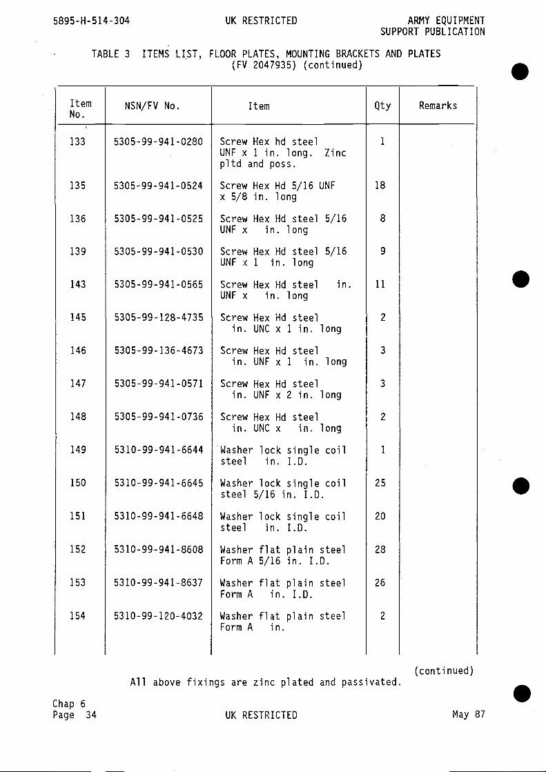
133
135
136
139
143
145
146
147
148
149
150
151
152
153
154
5305-99-941-0280
5305-99-941-0524
5305-99-941-0525
5305-99-941-0530
5305-99-941-0565
5305-99-128-4735
5305-99-136-4673
5305-99-941-0571
5305-99-941-0736
5310-99-941-6644
53 10-99-941-6645
53 10-99-941-6648
53 10-99-941-8608
5310-99-941-8637
53 10-99-120-4032
18
8
9
11
2
3
3
2
1
25
20
28
26
2
5895-H-514-304 UK RESTRICTED ARMY EQUIPMENTSUPPORT PUBLICATION
TABLE 3 ITEMS LIST, FLOOR PLATES, MOUNTING BRACKETS(FV 2047935) (continued)
AND PLATES
ItemNo.
NSN/FV No. Item Qty Remarks
1Screw Hex hd steelUNF x 1 in. long. Zincpltd and pass.
Screw Hex Hd 5/16 UNFx 5/8 in. long
Screw Hex Hd steel 5/16UNF x in. long
Screw Hex Hd steel 5/16UNF x 1 in. long
Screw Hex Hd steel in.UNF x in. long
Screw Hex Hd steelin. UNC x 1 in. long
Screw Hex Hd steelin. UNF x 1 in. long
Screw Hex Hd steelin. UNF x 2 in. long
Screw Hex Hd steelin. UNC x in. long
Washer lock single coilsteel in. I.D.
Washer lock single coilsteel 5/16 in. I.D.
Washer lock single coilsteel in. I.D.
Washer flat plain steelForm A 5/16 in. I.D.
Washer flat plain steelForm A in. I.D.
Washer flat plain steelForm A in.
.
S
S
SChap 6Page 34
All above fixings are zinc plated and passivated.
UK RESTRICTED
(conti nued)
May 87

ARMY EQUIPMENT UK RESTRICTED 5895-H-514-304SUPPORT PUBLICATION
TABLE 3 ITEMS LIST, FLOOR PLATES, MOUNTING BRACKETS AND PLATES(FV 2047935) (continued)
ItemNo.
NSN/FV No. Item Qty Remarks
155 BS 4929 (Pt 2) Nut Hex self lock steel 3 Forestin. UNF zinc plated Fasteners
and pass. or equiv.
156 BS 4929 (Pt 2) Nut Hex self lock steel 4 Forest5/16 in, UNF Fasteners
157 BS 4929 (Pt 2) Nut Hex self lock steel 4
in. UNF Zinc pltd andpass.
159 5305-99-122-5279 Screw csk Hd steel M4 4 Fig 9x 16 long
160 5305-99-122-5278 Screw, csk hd slotted 8 Fig 9steel M4 x 12 long
161 5305-99-122-5287 Screw csk Hd steel M5 8x 25 long
162 5305-99-138-3807 Screw Hex Hd steel M4 11
x 12 long
163 BS 3692 Screw Hex Hd steel M4 4 Fig 9x 16 long
165 5305-99-137-7590 Screw Hex Hd steel M4 16x 25 long
166 BS 3692 Screw Hex Nd steel M4 15x 30 long
167 5305-99-122-5356 Screw Hex Hd steel M5 8x 16 long
168 5305-99-135-0438 Screw Pan Hd slotted 16steel M6 x 10 long
169 5305-99-135-0439 Screw Pan Nd slotted 15steel M6 x 12 long
170 5305-99-135-0440 Screw Pan Nd slotted 56steel M6 x 16 long
(continued)
All above fixings are zinc plated and passivated.
Chap 6May 87 UK RESTRICTED Page 35

171 5305-99-135-0441 16
174 5305-99-122-5290 42
179 5305-99-122-5360 19
181 5305-99-122-5362 3
182 5305-99-122-5363 4
183 5305-99-122-5247 6
184 5305-99-135-0270 8
187 5305-99-122-5365 26
188 5305-99-122-5366 37
189 5305-99-122-5369 2
190 5305-99-122-4909 18
191 5305-99-122-4910 4
192 5305-99-122-5370 8
194 5310-99-138-9225 38
195 5310-99-137-9232 109
(conti nued)
Unless stated otherwise all fixings are zinc plated and passivated. •UK RESTRICTED May 87
TABLE 3 ITEMS LIST,
5895-H-514-304 UK RESTRICTED ARMY EQUIPMENTSUPPORT PUBLICATION
FLOOR PLATES, MOUNTING BRACKETS AND PLATES(FV 2047935) (continued)
ItemNo.
NSN/FV No. Item Qty Remarks
Screw Pan Hd slottedsteel M6 x 20 long
Screw csk hd slottedsteel M6 x 16 long
Screw Hex Hd steel M6x 16 long
Screw Hex Md steel M6x 25 long
Screw hex hd steel M6x 30 'ong
Bolt hex hd rn/c steelM6 x 45 long
Screw csk hd steel M8x 25
Screw hex hd steel M8x 16 long
Screw hex hd steel M8x 20 long
Screw hex hd steel M8x 40 long
Screw hex hd steel M10x 20 long
Screw hex hd steel M10x 25 long
Screw hex hd steel M1Ox 16 long
Washer lock single coilsteel M4
Washer lock single coilsteel M6
.
.Zinc pltdand chroniate
Zinc pltdand chromate
Chap 6Page 36
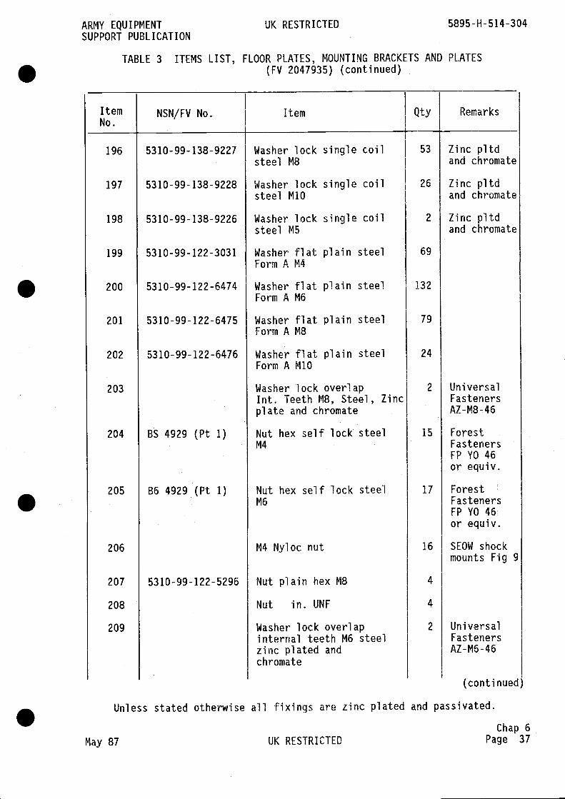
Washer lock single coilsteel M8
Washer lock single coilsteel M1O
Washer lock single coilsteel M5
Washer flat plain steelForm A M4
Washer flat plain steelForm A M6
Washer flat plain steelForm A M8
Washer flat plain steelForm A M10
Washer lock overlapmt. Teeth M8, Steel, Zincplate and chromate
Nut hex self lock steelM4
Nut hex self lock steelM6
Zinc pltdand chromate
Zinc pltdand chromate
Zinc pltdand chromate
UniversalFastenersAZ-M8-46
ForestFastenersFP YO 46or equiv.
ForestFastenersFP YO 46or equiv.
SEOW shockmounts Fig 9
ARMY EQUIPMENT UK RESTRICTEDSUPPORT PUBLICATION
TABLE 3 ITEMS LIST, FLOOR PLATES, MOUNTING BRACKETS AND(FV 2047935) (continued)
5895-H-514-304
PLATES
ItemNo.
NSN/FV No. Item Qty Remarks
196
197
198
199
200
201
202
203
204
205
206
207
208
209
53 10-99-138-9227
5310-99-138-9228
53 10-99-138-9226
5310-99-122-3031
53 10-99-122-6474
53 10-99-122-6475
53 10-99-122-6476
BS 4929 (Pt 1)
B6 4929 (Pt 1)
53 10-99-122-5296
53
26
2
69
132
79
24
2
15
17
16
4
4
2
M4 Nyloc nut
Nut plain hex M8
Nut in. UNF
Washer lock overlap Universalinternal teeth M6 steel Fastenerszinc plated and AZ-M6-46chromate
(conti nued
Unless stated otherwise all fixings are zinc plated and passivated.
Chap 6May 87 UK RESTRICTED Page 37
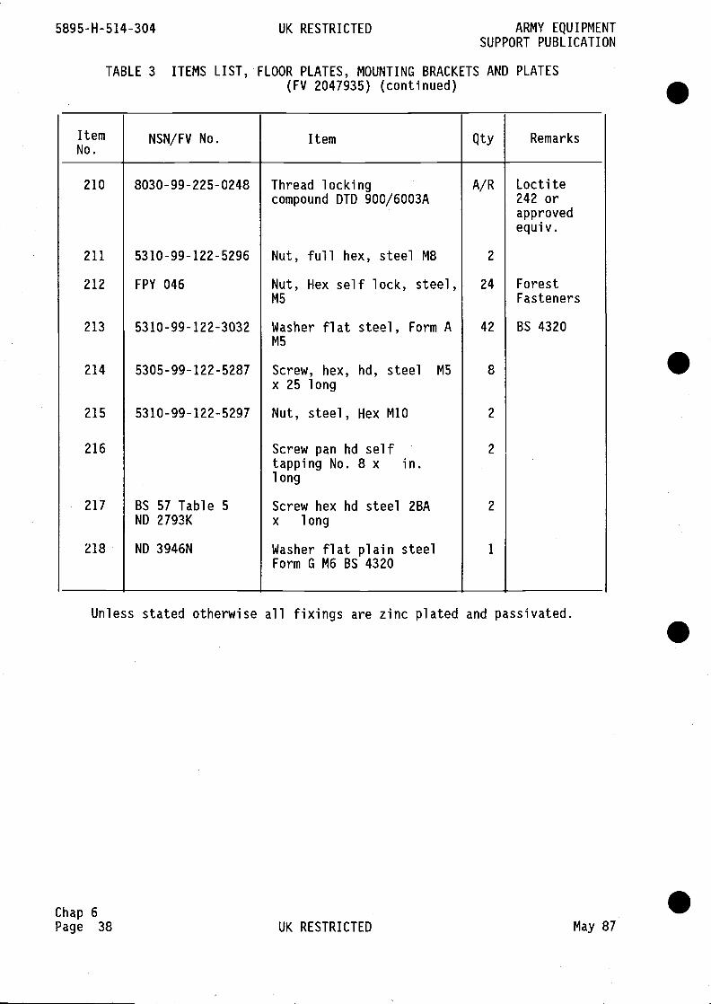
5895-H-514-304 UK RESTRICTED ARMY EQUIPMENTSUPPORT PUBLICATION
TABLE 3 ITEMS LIST, FLOOR PLATES, MOUNTING BRACKETS AND PLATES(FV 2047935) (continued)
Unless stated otherwise all fixings are zinc plated and passivated.
Chap 6Page 38 UK RESTRICTED May 87
.
S
ItemNo.
NSN/FV No. Item Qty Remarks
210 8030-99-225-0248 Thread lockingcompound DTD 900/6003A
A/R Loctite242 orapprovedequi v.
211 5310-99-122-5296 Nut, full hex, steel M8 2
212 FPY 046 Nut, Hex self lock, steel,M5
24 ForestFasteners
213 5310-99-122-3032 Washer flat steel, Form AM5
42 BS 4320
214 5305-99-122-5287 Screw, hex, hd, steel M5
x 25 long8
215 5310-99-122-5297 Nut, steel, Hex M1O 2
216 Screw pan hd selftapping No. 8 x in.long
2
217 BS 57 Table 5ND 2793K
Screw hex hd steel 2BAx long
2
218 ND 3946N Washer flat plain steelForm G M6 BS 4320
1
.
S
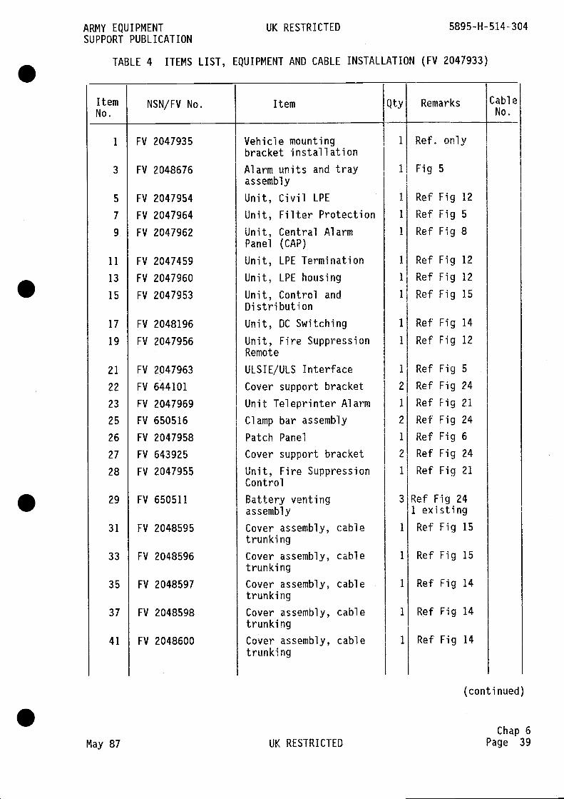
ARMY EQUIPMENT UK RESTRICTED 5895-H-514-304SUPPORT PUBLICATION
TABLE 4 ITEMS LIST, EQUIPMENT AND CABLE INSTALLATION (FV 2047933)
ItemNo.
NSN/FV No. Item Qty Remarks CableNo.
1 FV 2047935 Vehicle mounting 1 Ref. onlybracket installation
3 FV 2048676 Alarm units and tray 1 Fig 5assembly
5 FV 2047954 Unit, Civil LPE 1 Ref Fig 12
7 FV 2047964 Unit, Filter Protection 1 Ref Fig 5
9 FV 2047962 Unit, Central Alarm 1 Ref Fig 8Panel (CAP)
11 FV 2047459 Unit, LPE Termination 1 Ref Fig 12
13 FV 2047960 Unit, LPE housing 1 Ref Fig 12
15 FV 2047953 Unit, Control and 1 Ref Fig 15Distribution
17 FV 2048196 Unit, DC Switching 1 Ref Fig 14
19 FV 2047956 Unit, Fire Suppression 1 Ref Fig 12Remote
21 FV 2047963 ULSIE/ULS Interface 1 Ref Fig 5
22 FV 644101 Cover support bracket 2 Ref Fig 24
23 FV 2047969 Unit Teleprinter Alarm 1 Ref Fig 21
25 FV 650516 Clamp bar assembly 2 Ref Fig 24
26 FV 2047958 Patch Panel 1 Ref Fig 6
27 FV 643925 Cover support bracket 2 Ref Fig 24
28 FV 2047955 Unit, Fire Suppression 1 Ref Fig 21Control
29 FV 650511 Battery venting 3 Ref Fig 24assembly 1 existing
31 FV 2048595 Cover assembly, cable 1 Ref Fig 15trunking
33 FV 2048596 Cover assembly, cable 1 Ref Fig 15trunki ng
35 FV 2048597 Cover assembly, cable 1 Ref Fig 14trunki ng
37 FV 2048598 Cover assembly, cable 1 Ref Fig 14trunki ng
41 FV 2048600 Cover assembly, cable 1 Ref Fig 14trunki ng
(continued)
Chap 6May 87 UK RESTRICTED Page 39
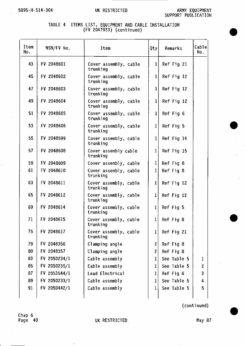
5895-H-514-304 UK RESTRICTED ARMY EQUIPMENTSUPPORT PUBLICATION
TABLE 4 ITEMS LIST, EQUIPMENT AND CABLE(FV 2047933) (continued)
INSTALLATION
ItemNo.
NSN/FV No. Item Qty Remarks CableNo.
FV 2048601
FV 2048602
FV 2048603
FV 2048604
FV 2048605
FV 2048606
FV 2048599
FV 2048608
FV 2048609
FV 2048610
FV 2048611
FV 2048612
FV 2048614
FV 2048615
FV 2048617
FV 2048356
FV 2048357
FV 2050234/1
FV 2050235/1
FV 2053544/1
FV 2050233/1
FV 2050442/1
Ref Fig 21
Ref Fig 12
Ref Fig 12
Ref Fig 12
Ref Fig 6
Ref Fig 5
Ref Fig 14
Ref Fig 15
Ref Fig 8Ref Fig 8
Ref Fig 12
Ref Fig 12
Ref Fig 5
Ref Fig 8
Ref Fig 21
43
45
47
49
51
53
55
57
59
61
63
65
69
71
75
79
80
83
85
87
89
91
Chap 6Page 40
Cover assembly, cabletrunki ng
Cover assembly, cabletrunki ng
Cover assembly, cabletrunki ng
Cover assembly, cabletrunki ng
Cover assembly, cabletrunki ng
Cover assembly, cabletrunki ng
Cover assembly, cabletrunki ng
Cover assembly cabletrunki ng
Cover assembly, cable
Cover assembly, cabletrunki ng
Cover assembly, cabletrunki ng
Cover assembly, cabletrunki ng
Cover assembly, cabletrunki ng
Cover assembly, cabletrunki ng
Cover assembly, cabletrunki ng
Clamping angle
Clamping angle
Cable assembly
Cable assembly
Lead ElectricalCable assembly
Cable assembly
1
1
1
1
1
1
1
1
1
1
1
1
1
1
1
2
2
1
1
1
1
1
.
S
.
S
Ref
Ref
See
See
Ref
See
See
Fig 8Fig 8Table 5 1
Table 5 2
Fig6 3
Table 5 4
Table 5 5
(continued)
UK RESTRICTED May 87

ARMY EQUIPMENT UK RESTRICTED 5895-H-514-304SUPPORT PUBLICATION
TABLE 4 ITEMS LIST, EQUIPMENT AND CABLE INSTALLATION (FV 2047933)(continued)
ItemNo.
NSN/FV No. Item Qty Remarks C.ableNo.
93 FV 2050440/1 Cable assembly 1 See Table 5 6
95 FV 2050442/1 Cable assembly 1 See Table 5 7
97 FV 2050440/2 Cable assembly 1 See Table 5 8
99 FV 2050232/1 Cable assembly 1 See Table 5 9
101 FV 2050439/1 Cable assembly 1 See Table 5 10
103 FV 2050236/1 Cable assembly 1 See Table 5 11
105 FV 2050439/2 Cable assembly 1 See Table 5 12
107 FV 2050236/2 Cable assembly 1 See Table 5 13
109 FV 2050439/3 Cable assembly 1 See Table 5 14
111 FV 2050236/3 Cable assembly 1 See Table 5 15
113 FV 2050233/2 Cable assembly 1 See Table 5 16
115 FV 2050231/1 Cable assembly 1 See Table 5 17
117 FV 2050230/1 Cable assembly 1 See Table 5 18
119 FV 2050230/2 Cable assembly 1 See Table 5 19
121 FV 2050230/3 Cable assembly 1 See Table 5 20
123 FV 2050229/1 Cable assembly 1 See Table 5 21
125 IV 2050229/2 Cable assembly 1 See Table 5 22
127 FV 2050236/4 Cable assembly 1 See Table 5 23
129 FV 2050236/5 Cable assembly 1 See Table 5 24
131 FV 2053540/7 Cable assembly 1 See Table 5 25
133 FV 2050210/1 Cable assembly 1 See Table 5 26
135 FV 2050227/1 Cable assembly 1 See Table 5 28
137 FV 2053545/10 Lead electrical 1 See Table 5 29
139 FV 2050228/1 Cable assembly 1 See Table 5 30
141 FV 2053563/10 Lead electrical 1 Fig 8 32
143 FV 2053539/14 Lead electrical 1 Fig 8 33
145 FV 2050225/1 Cable assembly 1 See Table 5 34
147 FV 2053548/13 Lead electrical 1 Fig 15 35
(continued)
Note
Cable No. refers to cable numbering in Table 5.
Chap 6May 87 UK RESTRICTED Page 41
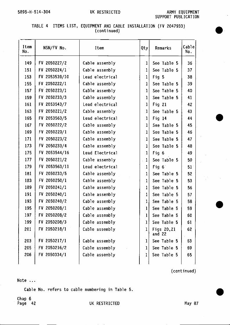
Note
ARMY EQUIPMENTSUPPORT PUBLICATION
TABLE 4 ITEMS LIST, EQUIPMENT AND CABLE INSTALLATION (FV 2047933)(conti nued)
(conti nued)
Cable No. refers to cable numbering in Table 5.
Chap 6Page 42 UK RESTRICTED May 87
5895-H-514-304 UK RESTRICTED
ItemNo.
NSN/FV No. Item Qty Remarks CableNo.
149
151
153
155
157
159
161
163
165
167
169
171
173
175
177
179
181
183
189
191
193
195
197
199
201
203
205
206
S
.
.
FV 2050227/2
FV 2050224/1
FV 2053539/10
FV 2050222/1
FV 2050223/1
FV 2050233/3
FV 2053543/7
FV 2050221/2
FV 2053563/5
FV 2050222/2
FV 2050220/1
FV 2050223/2
FV 2050233/4
FV 2053544/16
FV 2050221/2
FV 2053563/11
FV 2050233/5
FV 2050250/1
FV 2050241/1
FV 2050240/1
FV 2050240/2
FV 2050208/1
FV 2050208/2
FV 2050208/3
FV 2050218/1
FV 2050217/1
FV 2050216/2
FV 2050334/1
Cable assembly
Cable assembly
Lead electricalCable assembly
Cable assembly
Cable assembly
Lead electricalCable assembly
Lead electricalCable assembly
Cable assembly
Cable assembly
Cable assembly
Lead ElectricalCable assembly
Lead electricalCable assembly
Cable assembly
Cable assembly
Cable assembly
Cable assembly
Cable assembly
Cable assembly
Cable assembly
Cable assembly
Cable assembly
Cable assembly
Cable assembly
1
1
1
1
1
1
1
1
1
1
1
1
1
1
1
1
1
1
1
1
1
1
1
1
1
1
1
1
See Table 5
See Table 5
Fig 5See Table 5
See Table 5
See Table 5
Fig 21
See Table 5
Fig 14See Table 5
See Table 5
See Table 5
See Table 5
Fig 6See Table 5
Fig 6See Table 5
See Table 5
See Table 5
See Table 5
See Table 5
See Table 5
See Table 5
See Table 5
Figs 20,21and 22
See Table 5
See Table 5
See Table 5
36
37
38
39
40
41
42
43
44
45
46
47
48
49
50
51
52
53
56
57
58
59
60
61
62
63
69
65
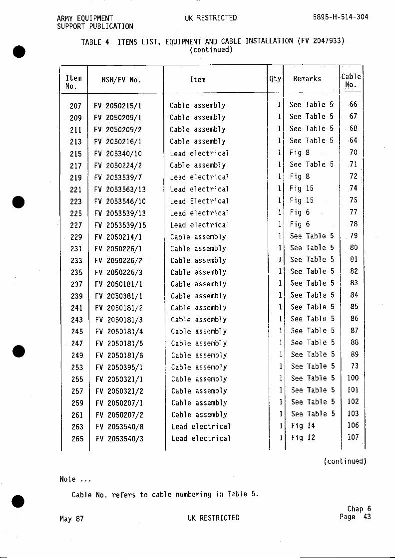
207
209
211
213
215
217
219
221
223
225
227
229
231
233
235
237
239
241
243
245
247
249
253
255
257
259
261
263
265
Note
FV 2050215/1
FV 2050209/1
FV 2050209/2
FV 2050216/1
FV 205340/10
FV 2050224/2
FV 2053539/7
FV 2053563/13
FV 2053546/10
FV 2053539/13
FV 2053539/15
FV 2050214/1
FV 2050226/1
FV 2050226/2
FV 2050226/3
FV 2050181/1
FV 2050381/1
FV 2050181/2
FV 2050181/3
FV 2050181/4
FV 2050181/5
FV 2050181/6
FV 2050395/1
FV 2050321/1
FV 2050321/2
FV 2050207/1
FV 2050207/2
FV 2053540/8
FV 2053540/3
Cable assembly
Lead electricalCable assembly
Lead electricalLead electricalLead ElectricalLead electricalLead electricalCable assembly
Cable assembly
Cable assembly
Cable assembly
Cable assembly
Cable assembly
Cable assembly
Cable assembly
Cable assembly
Cable assembly
Cable assembly
Cable assembly
Cable assembly
Cable assembly
Cable assembly
Cable assembly
Lead electricalLead electrical
66
67
68
64
70
71
72
74
75
77
78
79
80
81
82
83
84
85
86
87
88
89
73
100
101
102
103
106
107
(conti nued)
Cable No. refers to cable numbering in Table 5.
May 87 UK RESTRICTED
Chap 6Page 43
ARMY EQUIPMENTSUPPORT PUBLICATION
TABLE 4 ITEMS LIST,
UK RESTRICTED 5895-H-514-304
EQUIPMENT AND CABLE INSTALLATION (FV 2047933)(continued)
ItemNo.
NSN/FV No. Item Qty Remarks CableNo,
Cable
Cable
Cable
assembly
assembly
assembly
1 See Table 5
1 See Table 5
1 See Table 5
1 See Table 5
1 Fig81 See Table. 5
1 Fig81 Fig 15
1 Fig 15
1 Fig 6
1 Fig 6
1 See Table 5
1 See Table 5
1 See Table 5
1 See Table 5
1 See Table 5
1 See Table 5
1 See Table 5
1 See Table 5
1 See Table 5
1 See Table 5
1 See Table 5
1 See Table 5
1 See Table 5
1 See Table 5
1 See Table 5
1 See Table 5
1 Fig 14
1 Fig 12
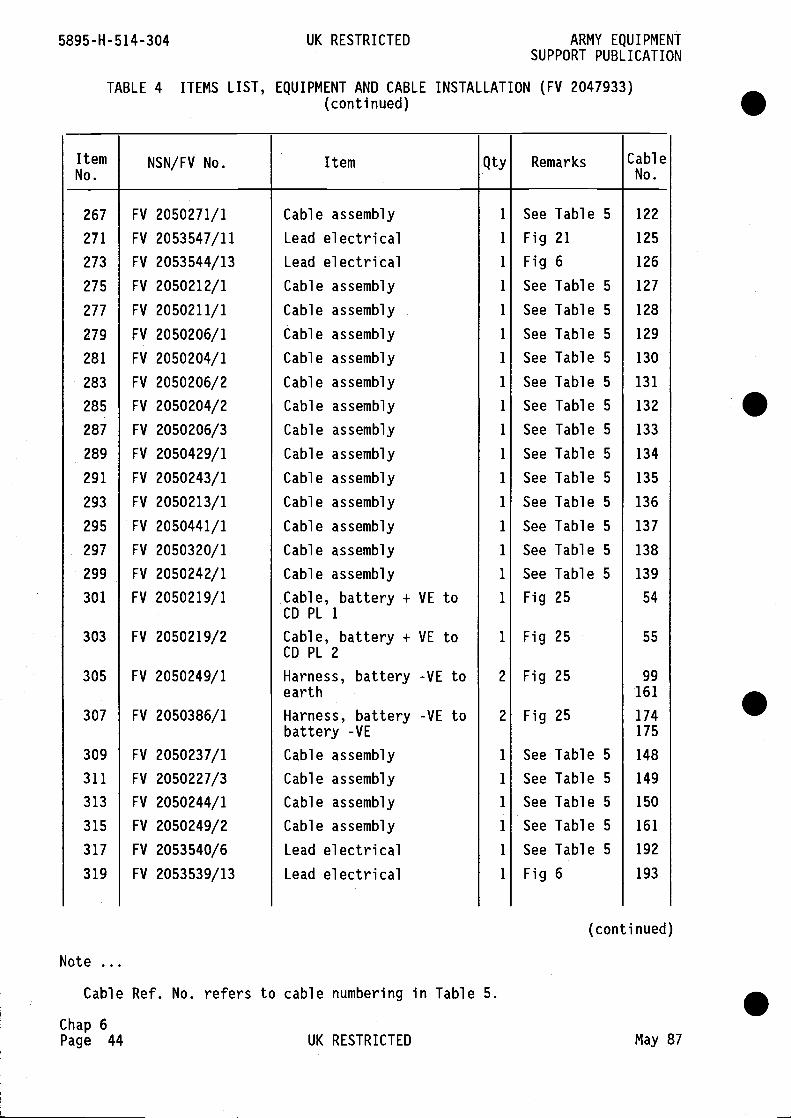
5895-H-514-304 UK RESTRICTED ARMY EQUIPMENTSUPPORT PUBLICATION
TABLE 4 ITEMS LIST, EQUIPMENT AND CABLE INSTALLATION (FV 2047933)(continued)
ItemNo.
NSN/FV No. Item Qty Remarks CableNo.
267 FV 2050271/1 Cable assembly 1 See Table 5 122
271 FV 2053547/11 Lead electrical 1 Fig 21 125
273 FV 2053544/13 Lead electrical 1 Fig 6 126
275 FV 2050212/1 Cable assembly 1 See Table 5 127
277 FV 2050211/1 Cable assembly 1 See Table 5 128
279 FV 2050206/1 Cable assembly 1 See Table 5 129
281 FV 2050204/1 Cable assembly 1 See Table 5 130
283 FV 2050206/2 Cable assembly 1 See Table 5 131
285 FV 2050204/2 Cable assembly 1 See Table 5 132
287 FV 2050206/3 Cable assembly 1 See Table 5 133
289 FV 2050429/1 Cable assembly 1 See Table 5 134
291 FV 2050243/1 Cable assembly 1 See Table 5 135
293 FV 2050213/1 Cable assembly 1 See Table 5 136
295 FV 2050441/1 Cable assembly 1 See Table 5 137
297 FV 2050320/1 Cable assembly 1 See Table 5 138
299 FV 2050242/1 Cable assembly 1 See Table 5 139
301 FV 2050219/1 Cable, battery + VE to 1 Fig 25 54CD PL 1
303 FV 2050219/2 Cable, battery + VE to 1 Fig 25 55CD PL 2
305 FV 2050249/1 Harness, battery -VE to 2 Fig 25 99earth 161
307 FV 2050386/1 Harness, battery -VE to 2 Fig 25 174battery -yE 175
309 FV 2050237/1 Cable assembly 1 See Table 5 148
311 FV 2050227/3 Cable assembly 1 See Table 5 149
313 FV 2050244/1 Cable assembly 1 See Table 5 150
315 FV 2050249/2 Cable assembly 1 See Table 5 161
317 FV 2053540/6 Lead electrical 1 See Table 5 192
319 FV 2053539/13 Lead electrical 1 Fig 6 193
(conti nued)
Note
Cable Ref. No. refers to cable numbering in Table 5.
Chap 6Page 44 UK RESTRICTED May 87

321
323
325
327
329
333
335
337
339
341
343
345
347
349
351
352
357
361
363
365
367
369
371
FV 2053539/8
FV 2053542/3
FV 2053542/4
FV 2053542/5
FV 2053541/8
FV 2053539/7
FV 2048333
FV 2048715
FV 2048336
FV 2050354/1
FV 2050353/1
FV 602488
FV 538370
FV 603998
FV 964639/7
FV 964639/5
5820-99-661-7471
electricalelectricalelectricalelectricalelectricalelectricalbelt, crew
Lead
Lead
Lead
Lead
Lead
Lead
Seal
Outline drawing ofNotice Board
Outline drawing of seatCable assembly
Cable assembly
Tee piece
Holding plateSecurity lightCable clipCable clipMounting assembly, Dataadaptor and Static SubSet (Plessey PT 5562-1-60 1054)
SEOW equipment (PT 5562-MR-500037-0O1)
ULSIE equipment(PT 2568-MR-500016)
LASE equipment (PlesseyPT 2568-0-500015)
Secondary Packet Switch(Plessey PT 0147-SA-500004)
TeleprinterTray assy Teleprinter
Fig 21
Fig 12
Fig 12
Fig 12
Fig 12
Fig 5Figs 5 & 14Fig 14
Figs 5 & 14See Table 5
See Table 5
Fig 25
Fig 25
Figs 8 & 21
Fig 8Fig 8Figs 6,15,21
Fig 15
Fig 8
Fig 5
Fig 15
Fig 6 & 14Figs 6 & 14
Note
Cable No. refers to cable numbering in Table 5.
(conti nued)
May 87 UK RESTRICTEDChap 6
Page 45
ARMY EQUIPMENTSUPPORT PUBLICATION
TABLE 4 ITEMS LIST,
UK RESTRICTED 5895-H-514-304
EQUIPMENT. AND CABLE INSTALLATION (FV 2047933)(conti riued)
ItemNo.
NSN/FV No. Item Qty Remarks CableNo.
'164
166
167
168
169
170
176
177
1
1
1
1
I
1
2
1
2
1
1
1
I
2
1
1
1
1
1
2
2
5841 -99-758-02 52
5805-99-663-2072
5805-99-663-1726
5820-99-661-7469
58 15-99-658-3064
5815-99-663-1306
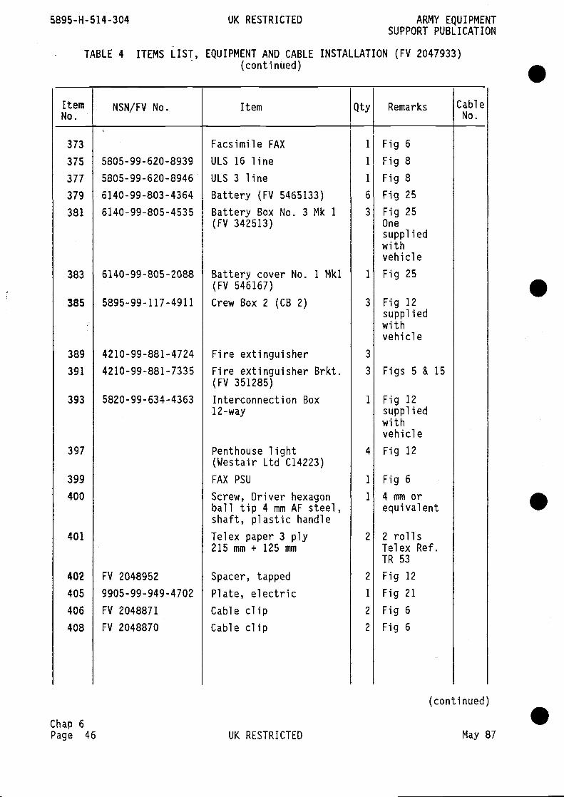
5895-H-514-304 UK RESTRICTED ARMY EQUIPMENTSUPPORT PUBLICATION
- TABLE 4 ITEMS LIST, EQUIPMENT AND CABLE INSTALLATION (FV 2047933)(continUed) •
ItemNo.
NSN/FV No. Item Qty Remarks CableNo.
373 Facsimile FAX 1 Fig 6
375 5805-99-620-8939 ULS 16 line 1 Fig 8
377 5805-99-620-8946 ULS 3 line 1 Fig 8
379 6140-99-803-4364 Battery (FV 5465133) 6 Fig 25
381 6140-99-805-4535 Battery Box No. 3 Mk 1 3 Fig 25(FV 342513) One
suppliedwithvehicle
383 6140-99-805-2088 Battery cover No. 1 Mkl 1 Fig 25(FV 546167)
385 5895-99-117-4911 Crew Box 2 (CB 2) 3 Fig 12suppi iedwithvehicle
389 4210-99-881-4724 Fire extinguisher 3
391 4210-99-881-7335 Fire extinguisher Brkt. 3 Figs 5 & 15(FV 351285)
393 5820-99-634-4363 Interconnection Box 1 Fig 1212-way supplied
withvehicle
397 Penthouse light 4 Fig 12(Westair Ltd C14223)
399 FAX PSU 1 Fig 6400 Screw, Driver hexagon 1 4 mm or
ball tip 4 mm AF steel, equivalentshaft, plastic handle
401 Telex paper 3 ply 2 2 rolls215 mm + 125 mm Telex Ref.
TR 53
402 FV 2048952 Spacer, tapped 2 Fig 12
405 9905-99-949-4702 Plate, electric 1 Fig 21
406 FV 2048871 Cable clip 2 Fig 6
408 FV 2048870 Cable clip 2 Fig 6
(conti nued)
Chap 6Page 46 UK RESTRICTED May 87
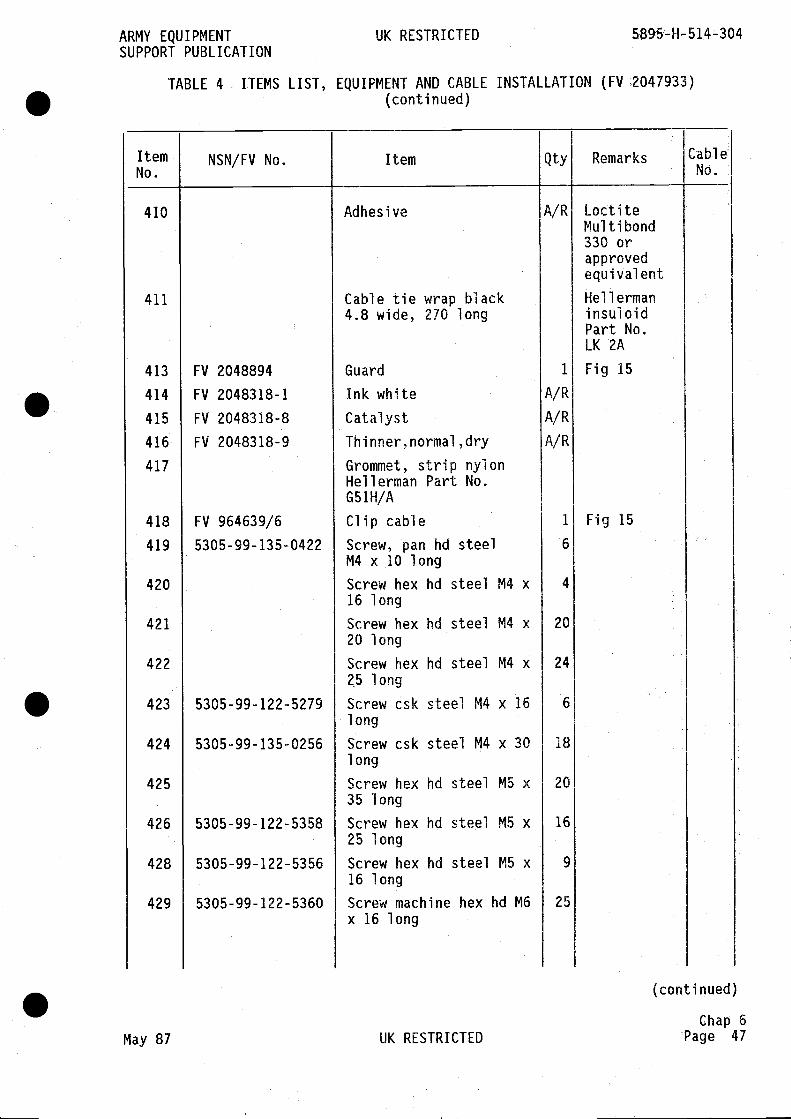
ARMY EQUIPMENT UK RESTRICTED 5895-H-514-304SUPPORT PUBLICATION
TABLE 4 ITEMS LIST, EQUIPMENT AND CABLE INSTALLATION (FV(conti nued)
[ternNo.
NSN/FV No. Item Qty Remarks CableNo.
410 Adhesive A/R LoctiteMulti bond330 orapprovedequivalent
411 Cable tie wrap black Hellerman4.8 wide, 270 long insuloid
Part No.LK 2A
413 FV 2048894 Guard 1 Fig 15• 414 FV 2048318-1 Ink white A/R
415 FV 2048318-8 Catalyst A/R
416 FV 2048318-9 Thinner,normal,dry A/R
417 Grommet, strip nylonHellerman Part No.G 51 H/A
418 FV 964639/6 Clip cable 1 Fig 15
419 5305-99-135-0422 Screw, pan hd steel 6
M4 x 10 long
420 Screw hex hdsteel M4 x 4
16 long
421 Screw hex hd steel M4 x 2020 long
422 Screw hex hd steel M4 x 2425 long
423 5305-99-122-5279 Screw csk steel M4 x 16 6
long
424 5305-99-135-0256 Screw csk steel M4 x 30 18long
425 Screw hex hd steel M5 x 2035 long
426 5305-99-122-5358 Screw hex hd steel M5 x 1625 long
428 5305-99-122-5356 Screw hex hd steel M5 x 9
16 long
429 5305-99-122-5360 Screw machine hex hd M6 25x 16 long
(conti nued)
Chap 6May 87 UK RESTRICTED Page 47
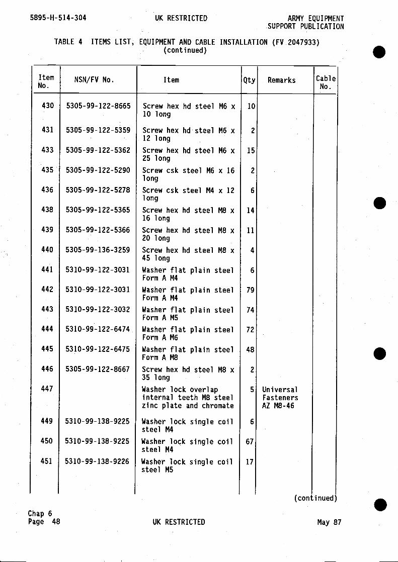
Chap 6Page 48
Screw hex hd steel M6 x10 long
Screw hex hd steel M6 x12 long
Screw hex hd steel M6 x25 long
Screw csk steel M6 x 161 ong
Screw csk steel M4 x 121 ong
Screw hex hd steel M8 x16 long
Screw hex hd steel M8 x20 long
Screw hex hd steel M8 x45 long
Washer flat plain steelForm A M4
Washer flat plain steelForm A M4
Washer flat plain steelForm A M5
Washer flat plain steelForm A M6
Washer flat plain steelForm A M8
Screw hex hd steel M8 x35 long
Washer lock overlapinternal teeth M8 steelzinc plate and chromate
Washer lock single coilsteel M4
Washer lock single coilsteel M4
Washer lock single coilsteel M5
UniversalFastenersAZ M8-46
5895-H-514-304 UK RESTRICTED ARMY EQUIPMENTSUPPORT PUBLICATION
TABLE 4 ITEMS LIST, EQUIPMENT AND CABLE INSTALLATION (FV 2047933)(continued)
ItemNo.
NSN/FV No. Item Qty Remarks CableNo.
430
431
433
435
436
438
439
440
441
442
443
444
445
446
447
449
450
451
5305-99-122-8665
5305-99-122-5359
5305-99-122-5362
5305-99-122-5290
5305-99-122-5278
5305-99-122-5365
5305-99-122-5366
5305-99-136-3259
53 10-99-122-3031
5310-99-122-3031
53 10-99-122-3032
53 10-99-122-6474
53 10-99-122-6475
5305-99-122-8667
53 10-99-138-9225
53 10-99-138-9225
5310-99-138-9226
10
2
15
2
6
14
11
4
6
79
74
72
48
2
5
6
67
17
.
.
S
S(continued)
UK RESTRICTED May 87
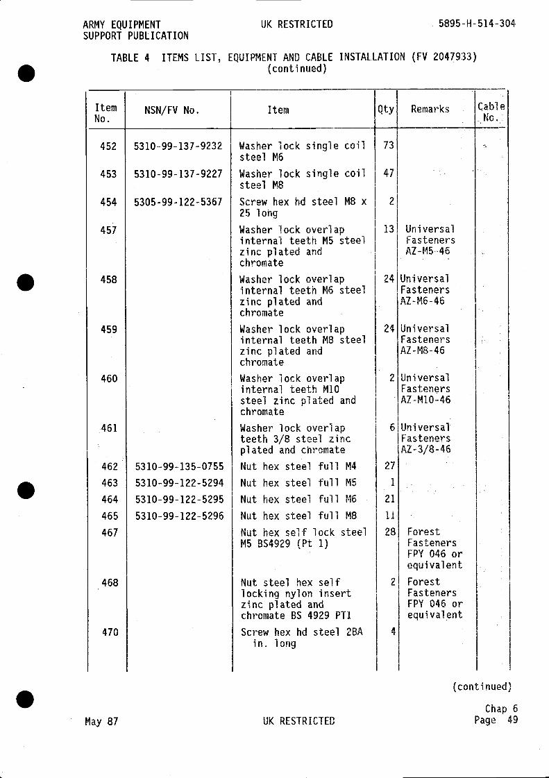
ARMY EQUIPMENT UK RESTRICTED 5895-H-514-304SUPPORT PUBLICATION
TABLE 4 ITEMS LIST, EQUIPMENT AND CABLE INSTALLATION (FV 2047933)(continued)
ItemNo.
NSN/FV No. Item Qty Remarks CableNo.
452 5310-99-137-9232 Washer lock single coil 73steel M6
453 5310-99-137-9227 Washer lock single coil 47steel M8
454 5305-99-122-5367 Screw hex hd steel M8 x 2
25 long
457 Washer lock overlap 13 Universalinternal teeth MS steel Fastenerszinc plated andchromate
458 Washer lock overlap 24 Universalinternal teeth M6 steel Fastenerszinc plated and AZ-M6-46chromate
459 Washer lock overlap 24 Universalinternal teeth M8 steel Fastenerszinc plated and AZ-M8-46chromate
460 Washer lock overlap 2 Universalinternal teeth M10 Fastenerssteel zinc plated and AZ-M10-46chromate
461 Washer lock overlap 6 Universalteeth 3/8 steel zinc Fastenersplated and chromate AZ-3/8-46
462 5310-99-135-0755 Nut hex steel full M4 27
463 5310-99-122-5294 Nut hex steel full M5 1
464 5310-99-122-5295 Nut hex steel full M6 21
465 5310-99-122-5296 Nut hex steel full M8 11
467 Nut hex self lock steel 28 ForestM5 BS4929 (Pt 1) Fasteners
FPY 046 orequivalent
468 Nut steel hex self 2 Forestlocking nylon insert Fastenerszinc plated and FPY 046 orchromate BS 4929 PT1 equivalent
470 Screw hex hd steel 2BA 4
in. long
(continued)
Chap 6May 87 UK RESTRICTED Page 49
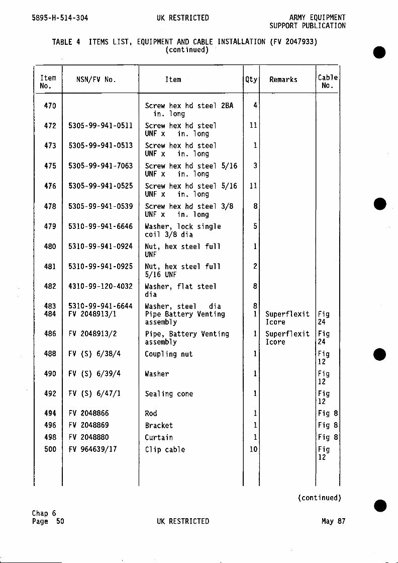
5895-H-514-304 UK RESTRICTED ARMY EQUIPMENTSUPPORT PUBLICATION
TABLE 4 ITEMS LIST, EQUIPMENT AND CABLE INSTALLATION (FV 2047933)(continued)
ItemNo.
NSN/FV No. Item Qty Remarks CableNo.
470 Screw hex hd steel 2BA 4
in. long472 5305-99-941-0511 Screw hex hd steel 11
UNF x in. long473 5305-99-941-0513 Screw hex hd steel 1
UNF x in. long475 5305-99-941-7063 Screw hex hd steel 5/16 3
UNF x in. long476 5305-99-941-0525 Screw hex hd steel 5/16 11
UNF x in. long478 5305-99-941-0539 Screw hex hd steel 3/8 8
UNF x in. long479 5310-99-941-6646 Washer, lock single 5
coil 3/8 dia480 5310-99-941-0924 Nut, hex steel full 1
UNF
481 5310-99-941-0925 Nut, hex steel full 2
5/16 UNF
482 4310-99-120-4032 Washer, flat steel 8di a
483 5310-99-941-6644 Washer, steel dia 8484 FV 2048913/1 Pipe Battery Venting 1 Superfiexit Fig
assembly Icore 24
486 FV 2048913/2 Pipe, Battery Venting I Superfiexit Figassembly Icore 24
488 FV (S) 6/38/4 Coupling nut 1 Fig12
490 FV (S) 6/39/4 Washer 1 Fig12
492 FV (S) 6/47/1 Sealing cone 1 Fig12
494 FV 2048866 Rod 1 Fig 8496 FV 2048869 Bracket 1 Fig 8498 FV 2048880 Curtain 1 Fig 8500 FV 964639/17 Clip cable 10 Fig
12
(conti nued)
Chap 6Page 50 UK RESTRICTED May 87
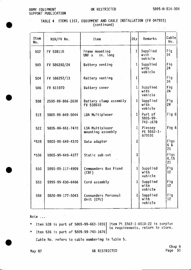
* Item 528 is part of 5805-99-663-1035] Item Pt 5562-1-6010-22 is surplus] to requirements, return to store.
* Item 536 is part of 5805-99-743-1676]
Cable No. refers to cable numbering in Table 5.
May 87 UK RESTRICTED
ARMY EQUIPMENT UK RESTRICTED 5895-H-514-304SUPPORT PUBLICATION
TABLE 4 ITEMS LIST, EQUIPMENT AND CABLE INSTALLATION (FV 047933)(continued)
ItemNo.
NSN/FV No. Item Qty Remarks CableNo.
502
503
504
506
508
515
522
*528
* 536
550
553
556
FV 538110
FV 586292/24
FV 586292/13
FV 611970
2590-99-866-2636
5805-99-649-5044
5805-99-661-7470
5805-99-649-4370
5805-99-649-4377
5895-99-117-4909
5995-99-630-6466
5820-99-177-5043
Frame mountingUNF x in. long
Battery venting
Battery venting
Battery cover
Battery clamp assemblyFV 538610
LDA Multiplexer
LDA Multiplexermounting assembly
Data adaptor
Static sub-set
Commanders Box Fixed(CBF)
Cord assembly
Commanders PersonalUnit (CPU)
1
1
1
1
1
1
1
2
3
1
1
1
SuppliedwithvehicleSuppliedwithvehicle
SuppliedwithvehicleSuppi i edwithvehiclePart of5805-99-743-1678
P1 esseyPt 5562-1-670101
SuppliedwithvehicleSuppliedwithvehicleSuppliedwithvehicle
Fig24
Fig24
Fig24
Fig24
Fig24
Fig 6
Fig 6
Figs6&21
Figs6,1521
Fig12
Fig12
Fig12
Note
Chap 6Page 51

5895-H-514-304 UK RESTRICTED
TABLE 5 LIST OF CABLE ASSEMBLIES
ARMY EQUIPMENTSUPPORT PUBLICATION
(continued)
Chap 6Page 52 UK RESTRICTED May 87
.
CableRef. NSN/FV No. HHI/MV RemarksNo.
.
.
.
1 FV 2050234/1 1031/1 LPE Termination to LDA Multiplexer Sk 22 FV 2050235/1 1032/1 LDA MUX Sk 3 to SEOW PL 1
3 FV 2053544/1 2014/1 LDA MUX earth to vehicle chassis4 FV 2050233/1 1030/1 LDA MUX PL 1 to Unit Control Distribution SK 4
5 FV 2050442/1 1187/1 Patch Panel PL 1 to LDA MUX Sk 86 FV 2050440/1 1181/1 Patch Panel PL 2 to LDA MUX Sk 77 FV 2050442/2 1187/2 Patch Panel PL 3 to LDA MUX Sk 6
8 FV 2050440/2 1188/2 Patch Panel PL 4 to LDA MUX Sk 59 FV 2050232/1 1029/1 LDA MUX Sk 4 to LDA MUX alarm Sk 2
10 FV 2050439/1 1186/1 LPE Termination Panel PL 2 to Patch Panel Sk I11 FV 2050236/1 1033/14 LPE Termination Panel PL 3 to Patch Panel Sk 2
12 FV 2050439/2 1186/2 LPE Termination Panel PL 4 to Patch Panel Sk 3
13 FV 2050236/2 1033/16 LPE Termination Panel PL 5 to Patch Panel Sk 4
14 FV 2050439/3 1186/3 LPE Termination Panel PL 6 to Patch Panel Sk 5
15 FV 2050236/3 1033/18 LPE Termination Panel PL 7 to Patch Panel Sk 6
16 FV 2050233/2 1030/2 Patch Panel PL 13 to Unit Control andDistribution Sk 13
17 FV 2050231/1 1028/1 Patch Panel PL 12 to ULSIE Sk 0218 FV 2050230/1 1027/1 Patch Panel PL 9 to Static Sub Set A Sk 219 FV 2050230/2 1027/2 Patch Panel PL 10 to Static Sub Set B Sk 220 FV 2050230/3 1027/3 Patch Panel PL 11 to Static Sub Set C Sk 221 FV 2050229/1 1026/3 Patch Panel PL 8 to SPS Sk H22 FV 2050229/2 1026/4 Patch Panel PL 7 to SPS Sk G23 FV 2050236/4 1033/19 Patch Panel PL 6 to SPS Sk F24 FV 2050236/5 1033/20 Patch Panel PL 5 to SPS Sk E25 FV 2053540/7 2010/1 Patch Panel earth to vehicle chassis26 FV 2050210/1 1007/1 ULSIE/ULS Interface Sk 2 to ULSIE Sk 0427
28 FV 2050227/1
Cablesuppl led1024/1
ULSIE keypad to ULSIE PL 1
ULSIE P101 to Unit Control and DistributionSK2 1
29 FV 2053545/10 2015/1 ULSIE earth to vehicl.e chassis

ARMY EQUIPMENT UK RESTRICTED 5895-H-514-304SUPPORT PUBLICATION
TABLE 5 LIST OF CABLE ASSEMBLIES (continued)
CableRef.No.
NSN/FV No. HHI/MV Remarks
30 FV 2050228/1 1025/1 LPE Termination Panel PL 8 to ULSIE/ULSInterface Sk 1
31 Supplied with unit ULS switchboard to ULS exchange unit
32 FV 2053563/10 2008/1 ULS switchboard earth to vehicle chassis33 FV 2053539/14 2009/1 ULS exchange unit earth to vehicle chassis34 FV 2050225/1 1022/1 Link Box No. 1 PL 25 to Unit Control and
Distribution PL 535 FV 2053548/13 2018/1 SEOW earth to vehicle chassis
36 FV 2050227/2 1024/2 LASE PL 01 to Unit Control and DistributionSk 16
37 FV 2050224/1 1021/1 LASE Sk 03 to Control Alarm Panel PL 3
38 FV 2053539/10 2009/2 LASE earth to vehicle chassis39 FV 2050222/1 1019/1 Static Sub Set A Sk 1 to Data Adaptor A Sk 440 FV 2050223/1 1020/1 Data Adaptor A Sk 2 to Teleprinter Alarm cable
PL 1
41 FV 2050233/3 1030/7 Data Adaptor A PL 1 to Unit Control andDistribution Sk 15
42 FV 2053543/7 2013/1 Data Adaptor A earth to vehicle chassis43 FV 2050221/1 1018/1 Teleprinter A to Unit Control and Distribution
Sk 18
44 FV 2053563/5 Teleprinter A to earth to vehicle chassis45 FV 2050222/2 1019/2 Static Sub Set B Sk 1 to Data Adaptor B Sk 446 FV 2050220/1 1017/1 Data Adaptor B Sk 1 to FAX Alarm Cable PL 1
47 FV 2050223/2 1020/2 Data Adaptor B Sk 2 to Teleprinter Alarm CableB PL 1
48 FV 2050233/4 1030/8 Data Adaptor B PL 1 to Unit Control andDistribution Sk 20
49 FV 2053544/16 2014/2 Data Adaptor B earth to vehicle chassis50 FV 2050221/2 1018/2 Unit Control and Distribution Sk 23 to
Teleprinter B51 FV 2053563/11 2008/3 Teleprinter B earth to vehicle chassis52 FV 2050233/5 1030/9 Unit Control and Distribution Sk 7 to Armoured
Outlet lights Sk 3
(continued)
Chap 6May 87 UK RESTRICTED Page 53

Chap 6Page 54 UK RESTRICTED May 87
5895-H- 514-304 UK RESTRICTED ARMY EQUIPMENTSUPPORT PUBLICATION
TABLE 5 LIST OF CABLE ASSEMBLIES (continued)
CableRef.No.
NSN/FV No. HHI/MV Remarks
FV 2050250/1
FV 2050219/1
53
54
55
56
57
58
59
60
61
62
63
64
65
66
67
68
69
70
71
1048/1
1016/1
1016/2
1038/1
1037/1
1037/2
1005/1
1005/2
1005/3
1015/1
1014/1
1013/1
113 1/1
1012/1
1006/1
1006/2
10 13/2
2010/2
102 1/2
FV
FV
FV
FV
FV
FV
FV
FV
FV
FV
FV
FV
FV
FV
FV
FV
FV
20502 19/2
205024 1/1
2050240/1
20502 40/2
2050208/1
2050208/2
2050208/3
2050218/1
2050217/ 1
20502 16/1
2050334/1
2050215/ 1
2050209/1
2050209/2
20502 16/2
2053540/10
2050224/2
Unit Control and DistributionPL 4
SK 11 to lB 3
Unit Control and DistributionBattery + VE
PL 1 to Comms
Unit Control and DistributionBattery + VE
PL 2 to APU
Unit Control and DistributionSwitching PL 6
SK 24 to DC
Unit Control and DistributionInterface Sk 1
PL 6 to APU
Unit Control and DistributionInterface Sk 2
PL 7 to APU
Unit Control and DistributionSwitching Sk 4
PL 4 to Unit DC
Unit Control and DistributionSwitching SK 3
PL 3 to Unit DC
Unit Control and DistributionSwitching PL 5
SK 1 to Unit DC
Unit Control and Distributionchassis - VE supply
SK 2 to vehicle
Unit Control and DistributionAlarm Panel PL 2
SK 19 to Central
Unit Control and DistributionLight 1
SK 8 to Security
Unit Control and Distribution SK 22 to SPS PLA
Unit Control and Distribution- PL 1
SK 17 to FAX PSU
Unit Control and DistributionPenthouse Light 1
SK 5 to
Unit Control and DistributionPenthouse Light 4
SK 6 to
Unit Control and DistributionSwitch
SK 9 to Blackout
Unit Control and Distributionchassis
earth to vehicle
Central Alarm PL 1 to SPS SK B
.
.
.
.(conti nued)

ARMY EQUIPMENTSUPPORT PUBLICATION
UK RESTRICTED 5895-H-514-304
TABLE 5 LIST OF CABLE ASSEMBLIES (continued)
CableRef.No.
NSN/FV No. HHI/MV Remarks
May 87 UK RESTRICTED
(conti nued)
Chap 6Page 55
72
73
74
75
76
77
78
79
80
81
82
83
84
85
86
87
88
89
90
91
92
93
94
95
96
97
98
99
100
101
102
FV 2053539/7
FV 2050395/1
FV 2053563/13
FV 2053546/10
Supplied withunitFV 2053539/13
FV 2053539/15
FV 2050214/1
FV 2050226/1
FV 2050226/2
FV 2050226/3
FV 2050181/1
FV 2050381/1
FV 2050181/2
FV 2050181/3
FV 2050181/4
FV 2050181/5
FV 2050181/6
FV 2050208/4
FV 2050208/5
FV 2050218/2
FV 2050218/5
FV 2050218/4
FV 2050218/3
No Cable
FV 2050249/1
FV 2050321/1
FV 2050321/2
FV 2050207/1
2009/3
1211/1
2008/6
2016/1
2009/5
2009/6
1011/1
1023/1
1023/2
1023/3
1045/1
1179/1
1045/2
1045/3
1045/4
1045/5
1045/6
1005/16
1005/17
1015/6
1015/9
1015/4
1015/7
1047/ 1
1118/2
1118/3
1004/1
Central Alarm Earth to vehicle chassisSPS Control SK 1 to SPS SK C
SPS earth to vehicle chassisStatic Sub Set C earth to vehicle chassisFAX to FAX PSU PL 1
FAX earth to vehicle chassisFAX PSU earth to vehicle chassisSecurity Light 1 to Security Light 2Penthouse Light 1 to Penthouse Light 2Penthouse Light 2 to Penthouse Light 3Penthouse Light 3 to Penthouse Light 412-Way Tee Box to CB 2 (driver) SK 1Audio Outlet to CB 2 (driver) SK 3CB 2 driver SK 2 to CBF SK 1
lB 3 SK 1 to CBF SK 2
IB3SK2toCB2M/CSK1CB 2 SASO SK 2 to CB 2 M/C SK 2
12-Way Tee box to CB 2 (SASO) SK 1
12-Way Tee box to ICJB
Earth rod cable to vehicle chassisFirewall 2 PL 1 to APU2 OUTPUT
Firewall 1 PL 1 to APU 1 output + VE
APU 1 Battery + VE to Firewall 1 SK 1
APU 2 Battery + VE to Firewall 2 SK 1APU 1 Battery - VE to Firewall 1 SK 2
APU 2 Battery - VE to Firewall 2 SK 2
Comms and NBC Battery - VE to vehicle chassisAPU Interface SK 4 to Unit DC Switching PL 4APU Interface SK 3 to Unit DC Switching PL 3APU Interface PL 3 to Unit DC Switching PL 1
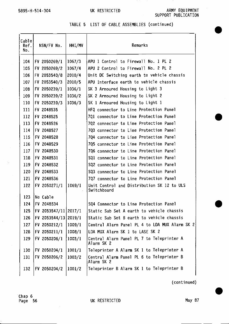
Chap 6Page 56
(conti nued)
UK RESTRICTED May 87
.
5895-H-514-304 UK RESTRICTED
TABLE 5 LIST OF CABLE ASSEMBLIES (continued)
ARMY EQUIPMENTSUPPORT PUBLICATION
CableRef. NSN/FV No. HHI/MV RemarksNo.
FV 2050269/1
FV 2050269/2
FV 2053540/8
FV 2053540/3
FV 2050239/1
FV 2050239/2
FV 2050239/3
FV 2048535
FV 2048525
FV 2048526
FV 2048527
FV 2048528
FV 2048529
FV 2048530
FV 2048531
FV 2048532
FV 2048533
FV 2048536
FV 2050271/1
.
S
S
104
105
106
107
108
109
110
111
112
113
114
115
116
117
118
119
120
121
122
123
124
125
126
127
128
129
130
131
132
1067/3
1067/4
2010/4
2010/5
1036/1
1036/2
1036/3
1069/1
2017/ 1
2019/1
1009/1
1008/1
1003/1
1001/1
1003/2
1001/2
APU 1 Control to Firewall No. 1 PL 2
APU 2 Control to Firewall No. 2 PL 2Unit DC Switching earth to vehicle chassisAPU Interface earth to vehicle chassisSK 3 Armoured Housing to Light 3SK 2 Armoured Housing to Light 2SK 1 Armoured Housing to Light 1HFQ connector to Line Protection Panel7Q1 connector to Line Protection Panel7Q2 connector to Line Protection Panel7Q3 connector to Line Protection Panel7Q4 connector to Line Protection Panel7Q5 connector to Line Protection Panel7Q6 connector to Line Protection PanelSQl connector to Line Protection PanelSQ2 connector to Line Protection PanelSQ3 connector to Line Protection Panel7Q7 connector to Line Protection PanelUnit Control and Distribution SK 12 to ULSSwi tchboard
SQ4 Connector to Line Protection PanelStatic Sub Set A earth to vehicle chassisStatic Sub Set B earth to vehicle chassisCentral Alarm Panel PL 4 to LDA MUX Alarm SK 2
LDA MUX Alarm SK 1 to LASE SK 2
Central Alarm Panel PL 7 to Teleprinter AAlarm SK 2
Teleprinter A Alarm SK 1 to Teleprinter ACentral Alarm Panel PL 6 to Teleprinter BAlarm SK 2
Teleprinter B Alarm SK 1 to Teleprinter B
No
FV
FV
FV
FV
FV
FV
Cable
2048534
2053547/11
2053544/13
20502 12/1
2050211/1
2050206/1
FV 2050204/1
FV 2050206/2
FV 2050204/2

ARMY EQUIPMENTSUPPORT PUBLICATION
UK RESTRICTED 5895-1-1-514-304
TABLE 5 LIST OF CABLE ASSEMBLIES (continued)
(continued)
May 87 UK RESTRICTEDChap 6
Page 57
CableRef.No.
NSN/FV No. HHI/MV Remarks
Central Alarm Panel PLUnit FAX Alarm SK 1 to
Civil LPE PL 1 to UnitULSIE/ULS Interface PL
Unit DC Switching SK 2
Unit DC Switching SK 1
Unit Filter ProtectionSW 80
5 to FAX Alarm SK 2
FAX PL 1
Filter Protection 5K 11 to ULS Switchboard
to APU Interface 137to Unit APU InterfacePL 1 to Exchange Unit
133
134
135
136
137
138
139
140
141
142
143
144
145
146
147
148
149
150
151
152
153
154
155
156
157
FV 2050206/3
FV 2050429/1
FV 2050243/1
FV 2050213/1
FV 2050441/1
FV 2050320/1
FV 2050242/1
FV 2050208/6
FV 2050208/7
No cable
No cable
No cable
No cable
No cable
FV 2050237/1
FV 2050227/3
FV 2050244/1
FV 2050268/1
FV 2050335/2
FV 2050387/1
FV 2050358/1
FV 2050335/1
FV 2050387/2
FV 2050358/2
1003/3
100 2/1
1040/ 1
1010/1
1190/ 1
1117/2
103 9/1
1005/18
1005/19
103 4/1
1024/3
1041/1
1046/1
113 2/2
1189/ 1
1156/ 1
1132/1
1189/ 2
1156/2
APU 2 output - VE to Firewall 2 SK 3Firewall 1. SK 3 to APU 1 output -yE
7Q8 Connector to Civil LPE
Unit Control and Distribution to SK 3 APUInterface PL 6Unit Fire Suppression SK 1 to Unit Fire RemotePL 1
APU Interface SK 14 to Unit Fire SuppressionPL 1
Box Fire Warning Junction PL 1 to APUInterface SK 11Box Fire Warning Junction SK 1 to FireExtingui sher
Firewall No. 1 (SK 4) to Box Fire WarningJunction SK 4
Detector B and C 1 to Firewall I SK 4Box Fire Warning Junction SK 3 to FireExtinguisherBox Fire Warning Junction SK 2 Junction SK 4to Detector A2Detector B and C 2 to Firewall 2 SK 4
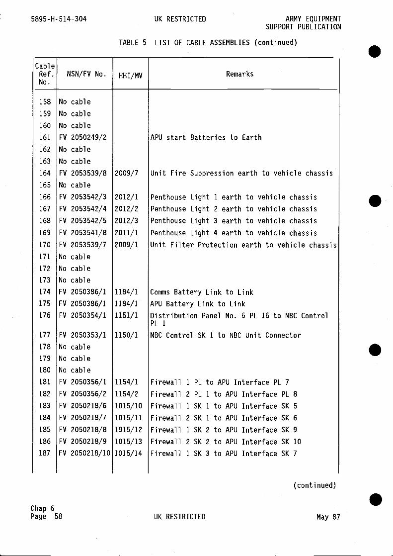
5895-H-514-304 UK RESTRICTED
TABLE 5 LIST OF CABLE ASSEMBLIES (continued)
Chap 6Page 58 UK RESTRICTED May 87
ARMY EQUIPMENTSUPPORT PUBLICATION
CableRef.No.
NSN/FV No. HHI/MV Remarks
No
No
No
FV
No
No
FV
No
FV
FV
FV
FV
FV
No
No
No
FV
FV
FV
cable
cable
cable
2050249/2
cable
cable
20 53 53 9/8
cable
2053542/3
2053542/4
2053 542/5
2053 541/8
2053539/7
cable
cable
cable
20 50386/1
20 50386/1
2050354/1
158
159
160
161
162
163
164
165
166
167
168
169
170
171
172
173
174
175
176
177
178
179
180
181
182
183
184
185
186
187
APU start Batteries to Earth
Unit Fire Suppression earth to vehicle chassis
Penthouse Light 1 earth to vehicle chassisPenthouse Light 2 earth to vehicle chassisPenthouse Light 3 earth to vehicle chassisPenthouse Light 4 earth to vehicle chassisUnit Filter Protection earth to vehicle chassis
Comms Battery Link to LinkAPU Battery Link to LinkDistribution Panel No. 6 PL 16 to NBC ControlPL 1
NBC Control SK 1 to NBC Unit Connector
2009/7
2012/ 1
20 12/2
20 12/3
20 11/1
2009/1
1184/ 1
1184/ 1
1151/1
1150/ 1
1154/ 1
1154/2
1015/10
1015/11
1915/12
1015/13
1015/14
.
.
.
.
FV 2050353/1
No cable
No cable
No cable
FV 2050356/1
FV 2050356/2
FV 20502 18/6
FV 2050218/7
FV 2050218/8
FV 2050218/9
FV 2050218/10
FirewallFirewallFirewallFirewallFirewallFirewallFirewall
1 PL to APU Interface PL 72 PL 1 to APU Interface PL 81 SK 1 to APU Interface SK 52 SK 1 to APU Interface SK 61 SK 2 to APU Interface SK 92 SK 2 to APU Interface SK 10I SK 3 to APU Interface SK 7
(conti nued)
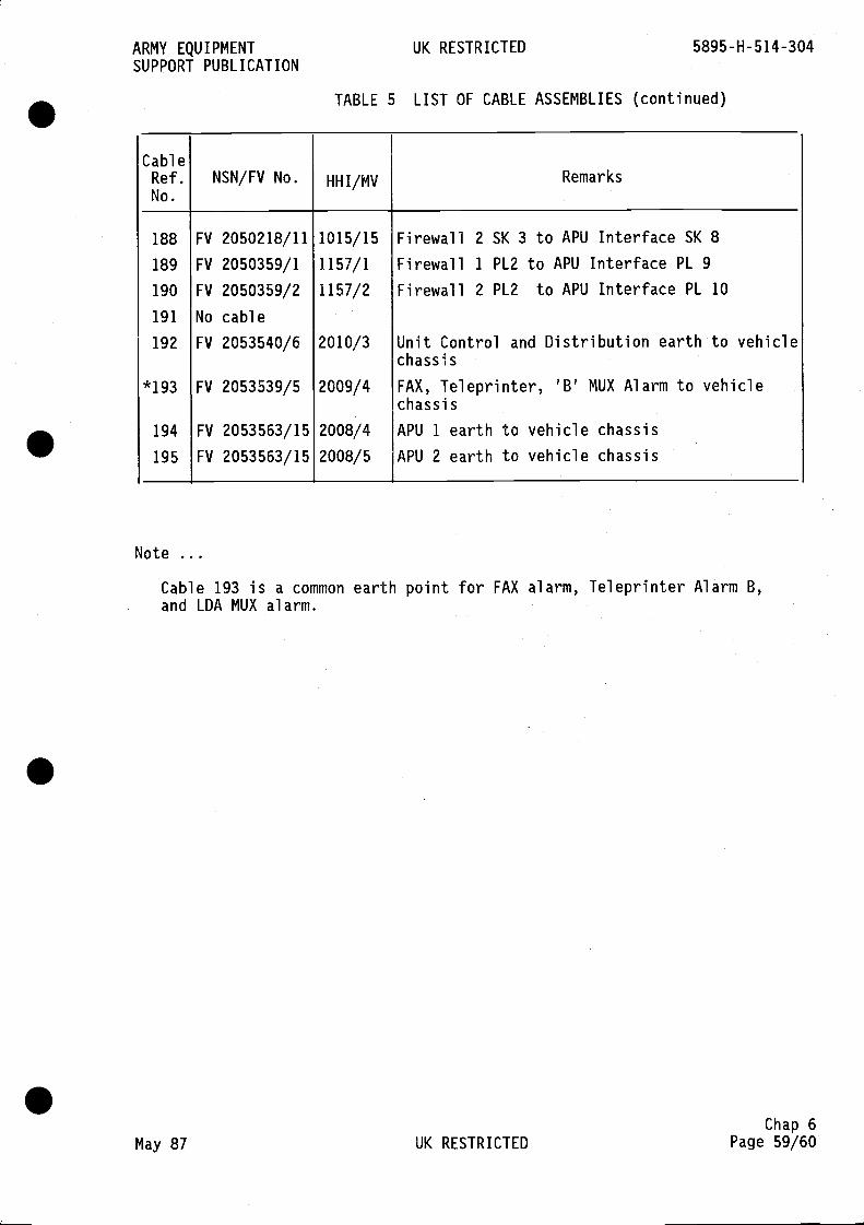
ARMY EQUIPMENT UK RESTRICTED 5895-H-514-304SUPPORT PUBLICATION
TABLE 5 LIST OF CABLE ASSEMBLIES (continued)
CableRef.No.
NSN/FV No. HHI/MV Remarks
188 FV 2050218/11 1015/15 Firewall 2 SK 3 to APU Interface SK 8
189 FV 2050359/1 1157/1 Firewall 1 PL2 to APU Interface PL 9
190 FV 2050359/2 1157/2 Firewall 2 PL2 to APU Interface PL 10
191 No cable
192 FV 2053540/6 2010/3 Unit Control and Distribution earthchassis
to vehicle
*193 FV 2053539/5 2009/4 FAX, Teleprinter, 'B' MUX Alarm tochassis
vehicle
194 FV 2053563/15 2008/4 APU 1 earth to vehicle chassis195 FV 2053563/15 2008/5 APU 2 earth to vehicle chassis
Note
Cable 193 is a common earth point for FAX alarm, Teleprinter Alarm B,and LDA MUX alarm.
Chap 6May 87 UK RESTRICTED Page 59/60

S
S
S
S
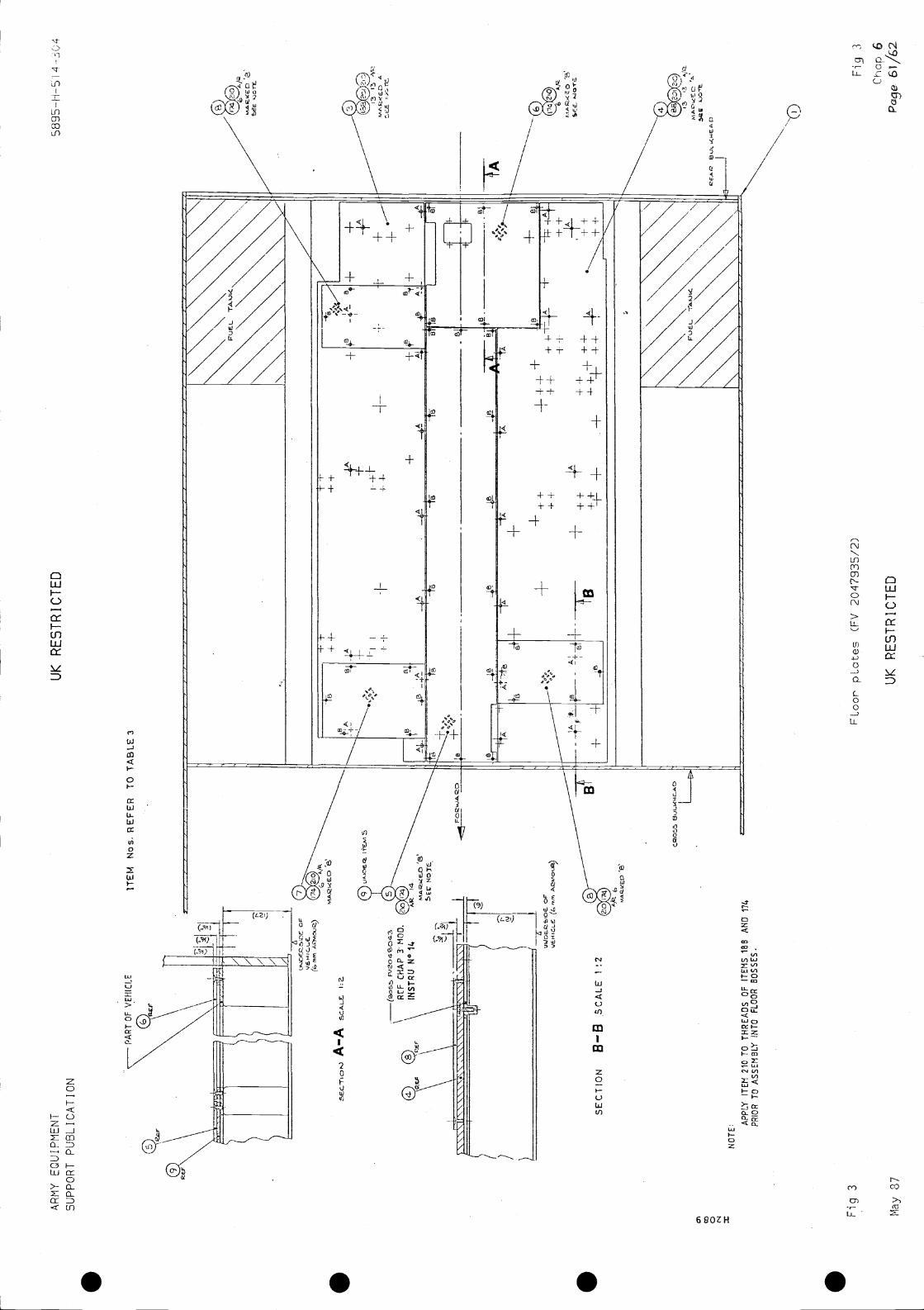
AR
MY
EQ
UIP
ME
NT
SU
PP
OR
T P
UB
LIC
AT
ION
UK
RE
ST
RIC
TE
D56
95—
ft-S
i
PA
RT
OF
VE
HIC
LE
A—
A
ITE
M M
os. R
EF
ER
TO
TA
BLE
3
&
TA
6
Fig
3F
Loor
' pLa
tes
(FV
204
7935
/2)
May
87U
KR
ES
TR
ICT
ED
SE
CT
ION
B—
B S
CA
LE 1
:2
6
0 N x
±+
NO
TE
:
++
T
AP
PLY
ITE
M 2
10 T
O T
HR
EA
DS
OF
ITE
MS
lBS
AN
D 1
74P
RIO
R T
O A
SS
EM
BLY
INT
O F
LOO
R B
OS
SE
S.
D
3 6P
age

. . . .
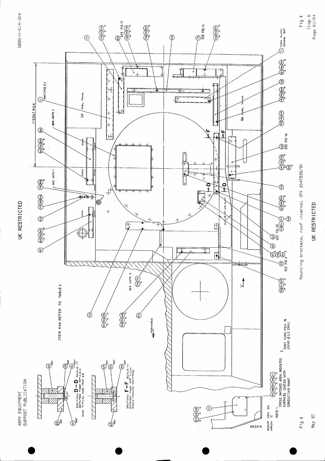
AR
MY
EQ
UIP
ME
NT
UK
RE
ST
RIC
TE
D4—
304
SU
PP
OR
T P
UB
LIC
AT
ION
ITE
M N
os.R
EF
ER
TO
TA
BLE
3
11
Mounting brackets, roof internaL (FV 2047935/9)
Chap 6
May 87
UK
RE
ST
RIC
TE
DP
age
63/6
4
D —
D:1
iTE
M
Fig
4
2.S
PO
TT
HR
OIT
EM
76
US
ING
DR
ILL
Fig 4

S S S S
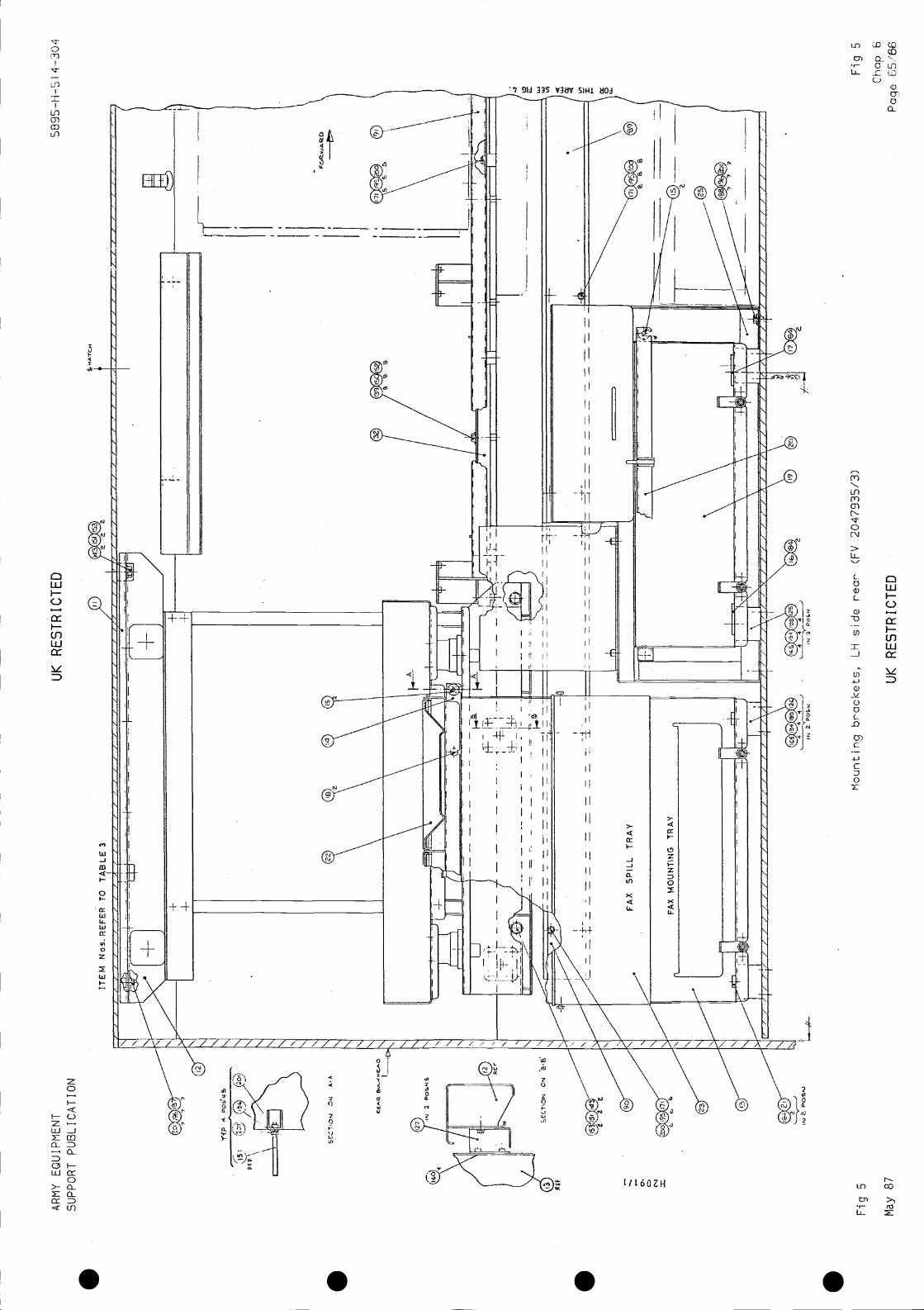
I
0 U-
52
Fig
5M
ount
ing
brac
kets
, LH
sid
e re
ar (
FV
204
7935
/3)
Fig
5
Cha
p 6
May
87
UK
RE
ST
RIC
TE
DP
age
65/6
6
ITE
M N
os.R
EF
ER
TO
I
--I
AR
MY
EQ
UIP
ME
NT
SU
PP
OR
T P
UB
LIC
AT
ION
NP
+
UK
RE
ST
RIC
TE
D
/0
H
HA
-rcH
t
5895
-H—
S I
4-30
4
N \
Tj
• •71
200
tI
FA
X S
PIL
L T
RA
Y0'
646
a
Fir
FA
XT
RA
Yn
(U.
1w
n
-/ /
/ /
/\/t/
/ /1/
// /
\/It
'X
/ /
// /\
\
.
2 P
0611
2P
O6U
w
II

. . . .
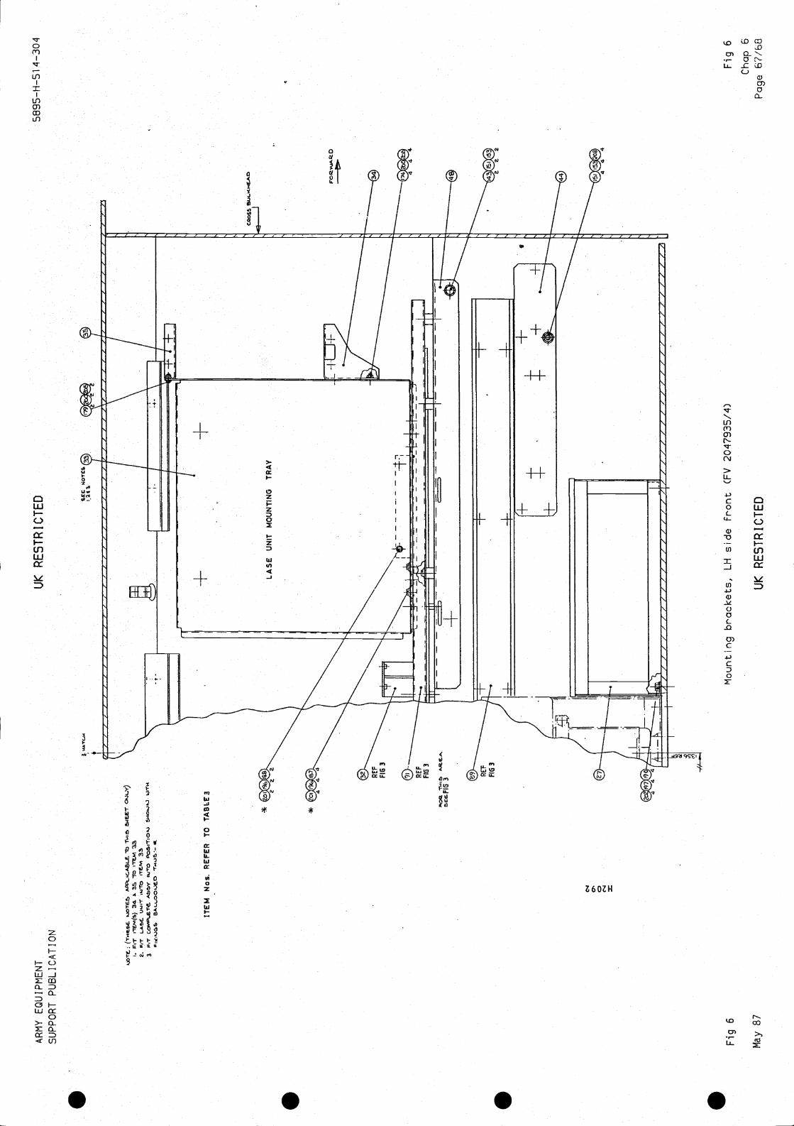
AR
MY
EQ
UIP
ME
NT
SU
PP
OR
T P
UB
L I C
AT
I O
N
UK
RE
ST
RIC
TE
D58
95—
H—
51 4
—30
4
lb0.
JLY
)I.
3410
iTE
M
3c
Abb
y ijr
Q*
ITE
M N
os. R
EF
ER
TO
TA
BLE
3
e4 0'
Fig
6M
ount
ing
brac
kets
, LH
sid
e F
ront
(F
V 2
0479
35/4
)
May
87
UK
RE
ST
RIC
TE
D
Fig
6C
hap
SP
age
67/b
O
*

S S S S
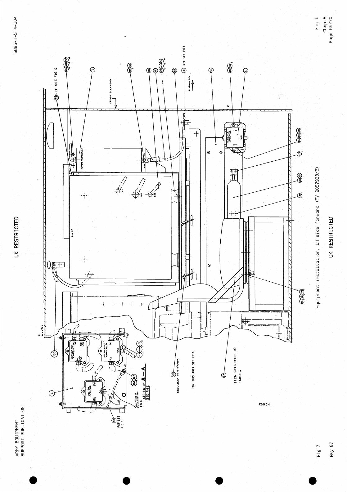
AR
MY
EQ
UIP
ME
NT
SU
PP
OR
T P
UB
LIC
AT
ION
UK
RE
ST
RIC
TE
D58
95-H
—51
4-3
04
RE
F S
EE
FIG
S
Equ
ipm
ent i
nsta
LLat
ion,
LH
sid
e fo
rwar
d (F
V 2
0579
33/3
)F
ig 7
May
87
UK
RE
ST
RIC
TE
D
RE
F S
EE
FIG
6
ITE
M N
os R
EF
ER
TO
TA
BLE
4
Fig
7C
hap
SP
age
69/7
0

. . . .
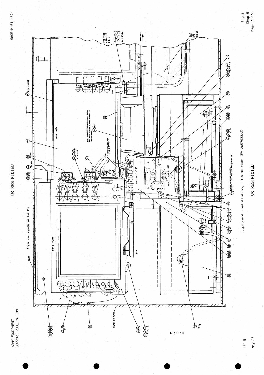

. . . .
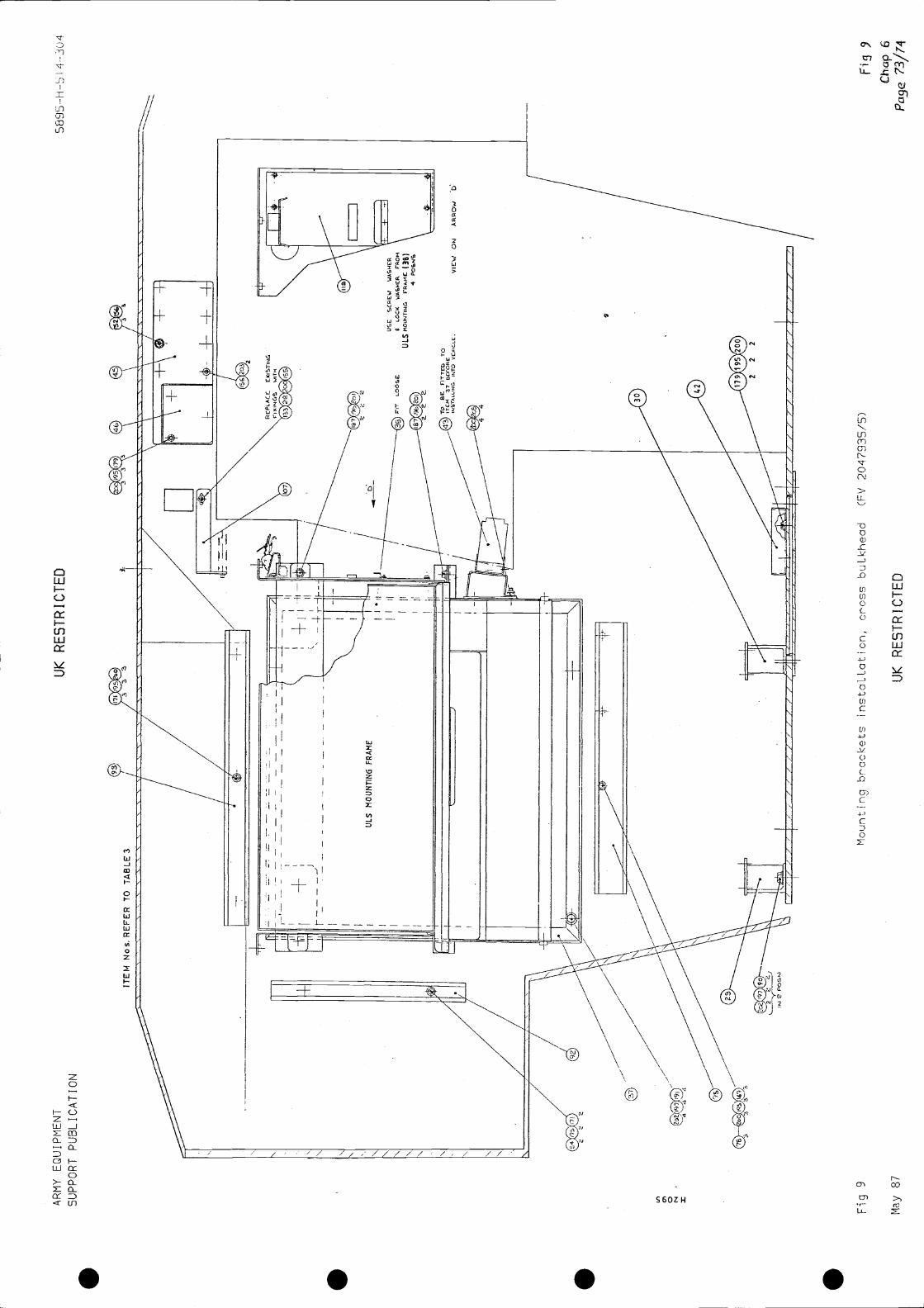
AR
MY
EQ
UIP
ME
NT
SU
PP
OR
T P
UB
LIC
AT
ION
UK
RE
ST
RIC
TE
DI 4
-3U
4
L)R
CS
CR
EW
WA
SH
ER
LOC
KW
AS
HE
R r
RO
HU
LSF
RA
ME
(3B
)4
PO
RN
S
Cha
p 6
May
87
UK
RE
ST
RIC
TE
DP
ane
73/7
4
Lfl
C., 0 N I
Fig
9M
ount
ing
brac
kets
inst
aLLa
tion,
cro
ss b
uLkh
ead
(FV
204
7935
/5)
FifJ

. . . .
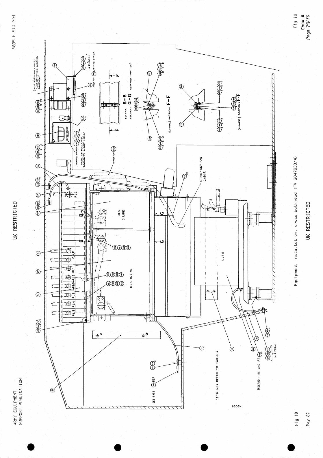
AR
MY
EQ
UIP
ME
NT
SU
PP
OR
T P
UB
LIC
AT
ION
UK
RE
ST
RIC
TE
D58
95-H
--S
i 4—
304
ITE
M N
os R
EF
ER
TO
TA
BLE
4
DIS
CA
RD
1 N
UT
AN
D
Fig
10
Equ
ipm
ent i
nsta
LLat
ion,
cro
ss b
uLkh
ead
(FV
204
7933
/4)
Cho
p 6
May
87
UK
RE
ST
RIC
TE
DP
a.ge
75/7
6
Fig
10

S S S S

AR
MY
EQ
UIP
ME
NT
UK
RE
ST
RIC
TE
D58
95-!
-5
4 -3
04S
UP
PO
RT
PU
BLI
CA
TIO
N
ITE
M N
os. R
EF
ER
TO
TA
8LE
3
BR
AC
PcE
TC
ON
TR
OL
(81Y
SE
CT
ION
I-I-
H S
EE
ALS
O F
IG 1
0
IN 6
PO
SN
S
FO
R T
HIS
AR
EA
SE
E
FIG
10
Fig
11
Bra
cket
s in
staL
Latio
n, R
H s
ide
forw
ard
(FV
204
7935
/6)
May
87
UK
RE
ST
RIC
TE
D
Fig
11 6
77/7
8
N 0 "4

S S S S

AR
MY
EQ
UIP
ME
NT
SU
PP
OR
T P
UB
LIC
AT
ION
UK
RE
ST
RIC
TE
D58
95—
il-S
'l—
J04
E-E
ALS
O F
109
FO
R T
HIS
AR
EA
SE
E F
tG 9
ITE
MN
os. R
EF
ER
TO
TA
BLE
3
c—c
Bra
cket
s in
staL
Latio
n, R
H s
ide
rear
(F
V 2
0479
35/7
)
UK
RE
ST
RIC
TE
D
Fig
12
May
87
Fic
j 12
flF ia
p 6
79/8
0

S S S S
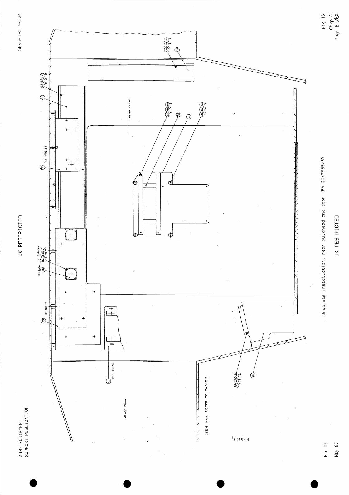
AR
MY
EQ
UIP
ME
NT
UK
RE
ST
RIC
TE
DS
UP
PO
RT
PU
BLI
CA
TIO
N
ITE
MN
os. R
EF
ER
TO
TA
BLE
3
Bra
cket
s in
staL
Latio
n, r
ear
buLk
head
and
doo
r (F
V 2
0479
35/B
)F
ig
Cha
p 6
May
87
UK
RE
ST
RIC
TE
D51
/82
Fig
13

. . . .

AR
MY
EQ
UIP
ME
NT
SU
PP
OR
T P
UB
LIC
AT
ION
UK
RE
ST
RIC
TE
D58
95-1
1-5
AS
$yF
V2O
467ô
1 T
0ô4
10
RE
FE
R T
O C
HA
P6
PA
RA
20
QU
AD
CO
NN
EC
TO
R A
SS
YS
SE
E F
i621
L.L.
T2'
UM
F*
2EF
iT$4
*N
OT
E -
HE
X £
PA
CE
2S01
4
USE
4-
WIT
HIT
EM
. RE
F O
NLY
SE
Efl
• Q
FMO
VL 11
-418
Equ
ipm
ent i
nsta
LLat
ion,
inte
rior
roof
(F
V 2
0479
33/8
)
£M
ay 8
7U
K R
ES
TR
ICT
ED
Fig
14
F i1
4

S S S S

OR
IEN
TA
TE
(N
IGH
T M
AR
K)Y
ELL
OW
701-
708
INC
L.(N
PO
SIT
ION
SH
OW
N.
VIE
W A
RR
OW
i(S
EE
TH
IS S
HE
ET
)
OR
IEN
TA
TE
(N
IGH
T M
AR
K)Y
ELL
OW
IN P
OS
ITIO
N S
HO
WN
VIE
WA
RR
OW
K(S
EE
TH
iS S
HE
ET
)
Fig
15
Qua
d co
nnec
tor'
inst
aLLa
tion
(FV
204
7934
/2)
May
87
UK
RE
ST
RIC
TE
D
AR
MY
EQ
UIP
ME
NT
SU
PP
OR
T P
UB
LIC
AT
ION
ITE
MN
os. R
EF
ER
TO
TA
BLE
1C
HA
P 5
UK
RE
ST
RIC
TE
D58
91-i-
-b I
B(C
ON
DU
IT A
SS
YA
RE
PT
. OF
ITE
M13
ON
FV
2047
933)
SE
CT
ION
C-C
VIE
W O
N A
RR
OW
K
EN
DT
HIS
SID
E)
SE
CT
ION
IIID
-fflI
Fig
15
Cho
p 6
Pag
e

S S S S
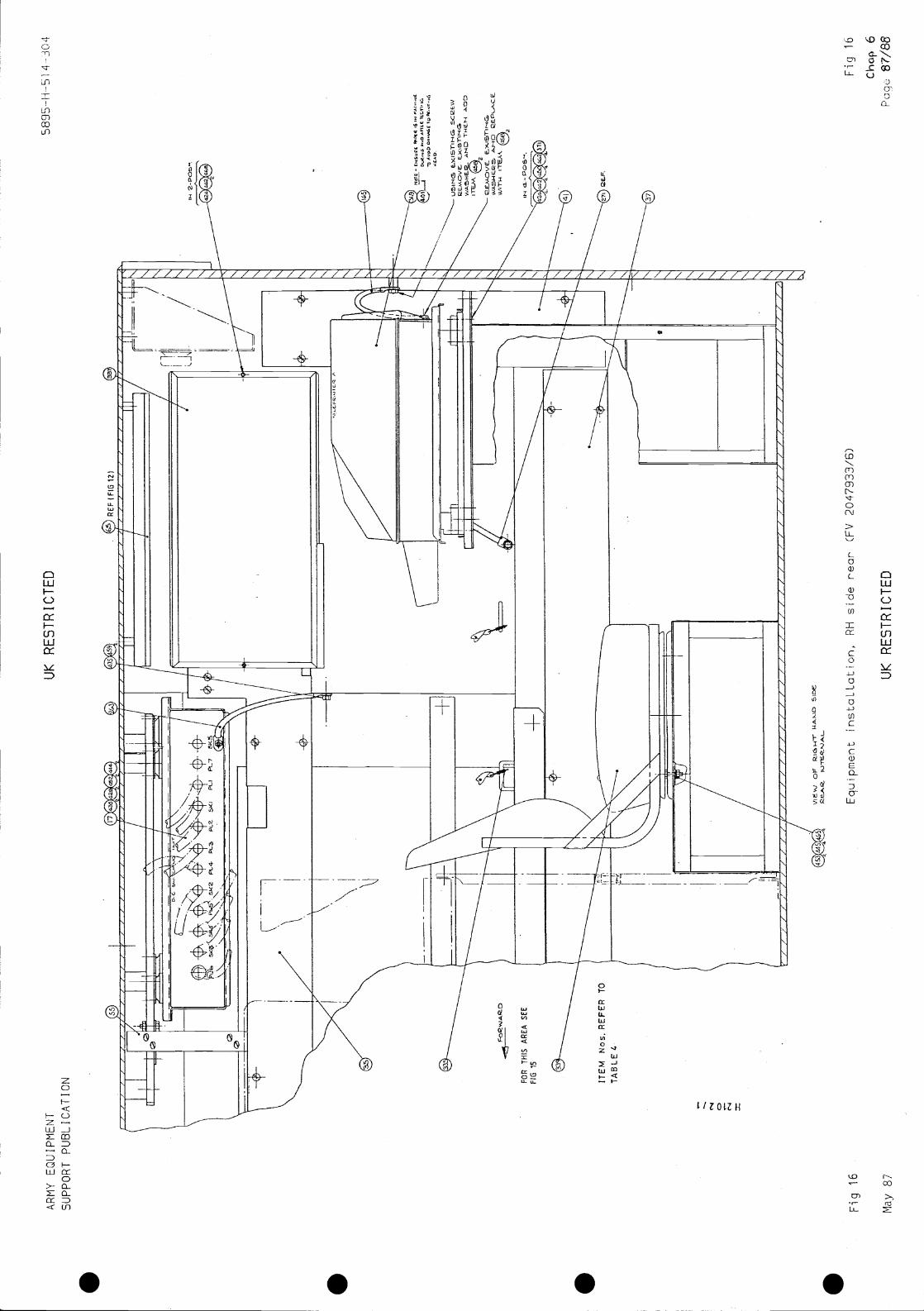
AR
MY
EQ
UIP
ME
NT
UK
RE
ST
RIC
TE
D4-
3()4
SU
PP
OR
T P
UB
LIC
AT
ION F
OR
TI-
HS
AR
EA
SE
EN
O 1
5
Out
PE
$A
VO
DT
O
rEM
.
•
VII
TI-
4
ITE
M N
os. R
EF
ER
TO
OF
Fig
16
Equ
ipm
ent i
nsta
LLat
ion,
RH
sid
e re
ar'
CF
V 2
0479
33/6
)
May
87
UK
RE
ST
RIC
TE
D
Fig
16
Cho
p 6
Paq
u 87
/88

S S S S
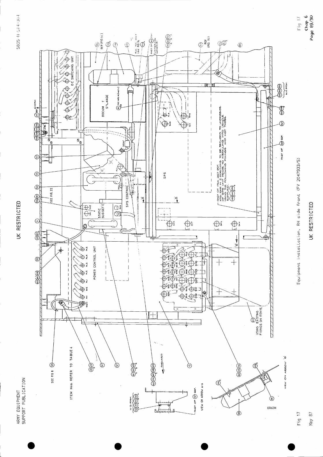
AR
MY
EQ
UIP
ME
NT
UK
RE
ST
RIC
TE
DS
UP
PO
RT
PU
BLI
CA
TI O
N
SE
E F
IGS
ITE
M N
os.
484
PL2.
P(3
PL4
PL5
--
-
RE
FIF
IG 1
')
__\
\\
\
44$
Equ
ipm
ent i
nsta
LLat
ion,
RH
sid
e F
ront
(F
V 2
0479
33/5
)
May
87
UK
RE
ST
RIC
TE
DC
hcip
6
III
/SE
E F
IG. 2
2
\
II
PO
WE
R C
ON
TR
OL
UN
IT
-S
TA
TIC
—i
SU
BS
ET
C—
j-n
I-fl
—1-
---—
— —
/
L
I
+±
/
US
ING
EX
IST
ING
/F
IXIN
GS
ON
ITE
M 1
5.
-F
/
0
-±
-s
-I
I
—
r-Q
1/
P—p
JO
F S
2S U
HIT
IHT
/O/
Al-/
cD H
OT
I5,
LJ7R
U6-
0.,
I
UI
N
RE
F(F
IG 1
41
VIE
$¼/ O
P-P
17
7/77
//A//I
_41/
/ / /
/ 77
/ / /
/ / /
/ / /
/ AI
II
4
Fiq
7
89/S
O

S S S S
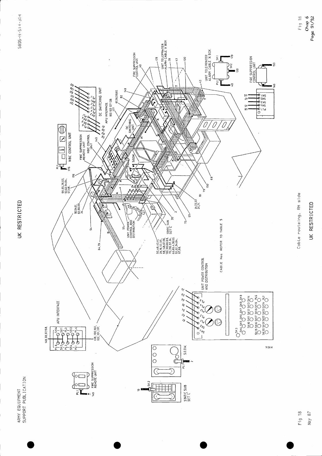
AR
MY
EQ
UIP
ME
NT
SU
PP
OR
T P
UB
LIC
AT
ION
UK
RE
ST
RIC
TE
D58
95-H
-SI
LI
j49
FIR
E S
UP
PR
ES
SIO
NR
EM
OT
E U
NIT
19
ST
AT
IC S
UB
SE
T C
'
CabLe routeing, RH
side
Chap 6
May 87
UK
RE
ST
RIC
TE
DP
age
AP
U IN
TE
RF
AC
E
66 ,6
536
.63,
176
NB
C C
ON
TR
OL
UN
IT
FIR
E S
UP
PR
ES
SIO
NR
EM
OT
E U
NIT
NB
C C
ON
TR
OL
tiNT
7I//
I//I
SU
PP
RE
SS
ION
UN
IT.
I L_"
LI"
4U
NIT
PO
WE
R C
ON
TR
OL
AN
D D
IST
RIB
UT
ION
29
CA
BLE
Nos
RE
FE
R T
O T
AB
LES
69
OS
K3
5K4
5K5
SK
6K
7 5K
B 5
KB
000
00S
K1O
SK
I1 S
K12
SK
13 S
KI4
0000
051
(155
1(16
SK
17 5
1(18
51(1
9P
L6
0000
0051
(205
2151
(22
SK
23 5
1(24
PL7
0000
00
UN
IT T
ELE
PR
INT
ER
ALA
RM
CA
BLE
A B
OX
Fig
18
SK
I
130
FIR
E S
UP
PR
ES
SIO
NC
ON
TR
OL
UN
IT
140
150
Fiq 18

S S S S
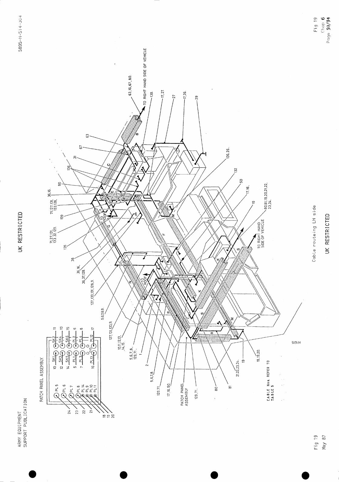
AR
MY
EQ
UIP
ME
NT
SU
PP
OR
T P
UB
LIC
AT
ION
UK
RE
ST
RIC
TE
D
23 /
22/'
21f /
18 /
PA
TC
H P
AN
EL
AS
SE
MB
LY.
PA
TC
H
AS
SE
MB
LY
63, 1
6 , 6
7, S
O.
HA
ND
SID
E O
F V
EH
ICLE
C'abLe routeing LH side
UK
RE
ST
RIC
TE
DP
aqe
93/9
4
FL
5
247
PL
6
FL
7
FL
8
FL
14
PL9
PL1
OF
Lu
II
10
SIK
I®ii
12S
IK30
13
14®
SIK
G15
5P
L1®
®P
L26
7B
001 P
L12
17
71,2
7,13
1,71
,127
,131
,13
3. 3
2.12
9.13
3,12
8,
,,16.
38
—
67
5,6,
7,8,
129,
71
2
129,
71.
139.
81
17,2
7
19
-29
CA
BLE
Nos
. RE
FE
R T
OT
AB
LE 5
132
TO
RIG
HT
HA
ND
SID
E O
F V
EH
ICLE
Fig
19
May
87
IC)
LtD
Fig 19
('hap
6

. . . .
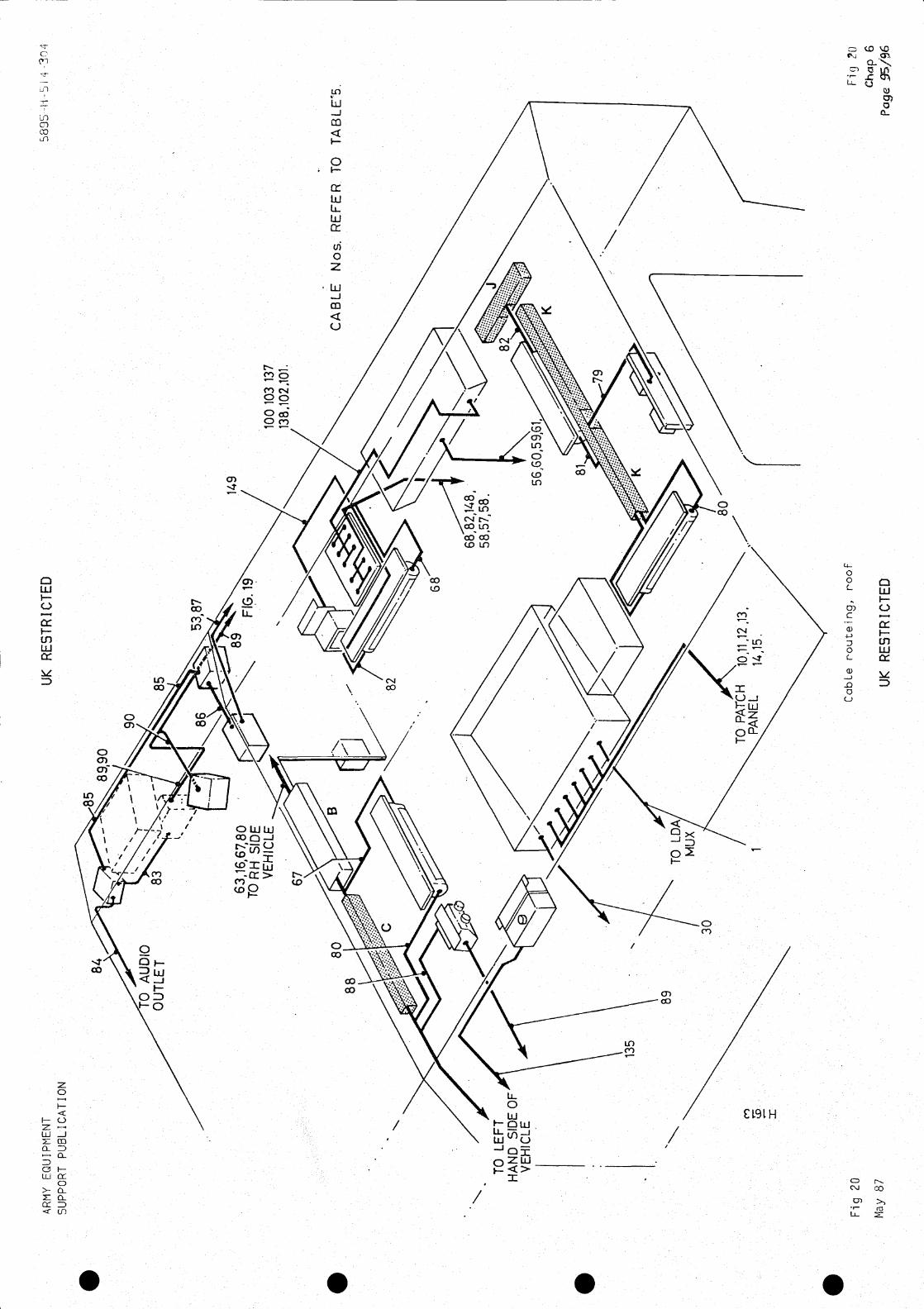
AR
MY
EQ
UIP
ME
NT
SU
PP
OR
T P
UB
LIC
AT
ION
89,9
0
UK
RE
ST
RIC
TE
D
AU
DIO
OU
TLE
T
90
85
53,8
7
63,1
6,67
,80
TO
RH
SID
EV
EH
ICLE
67
100
103
137
80C
AB
LE N
os. R
EF
ER
TO
TA
BLE
5.
TO
LE
FT
HA
ND
SID
EV
EH
ICLE
135
30
1
68,8
2,14
8,58
,57,
58.
Cab
Lero
ofF
ig 2
1)C
hcp
6U
K R
ES
TR
ICT
ED
149
89
3
Fig
20
May
87

S S S S
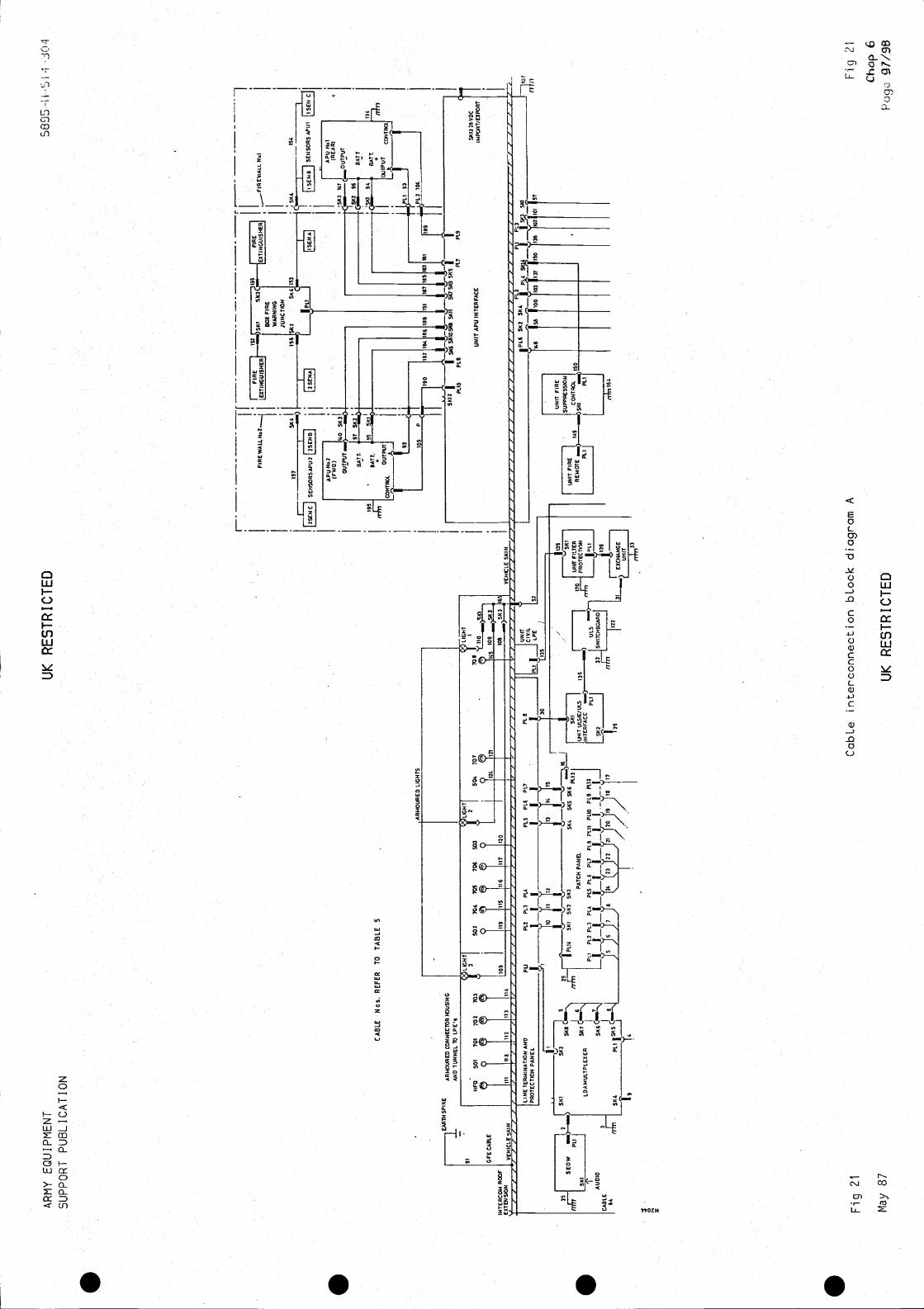
ARMY EQUIPMENT
SUPPORT PUBLICATION
UK
RE
ST
RIC
TE
D58
95 -
H-S
N J
Ol
PIt
P1.
2PL
3P
1.4
P1.
5P
16F
L?
III
II
II
157
SE
NS
OR
S A
PU
2
I
I IC
ON
TR
Ol.
Tc—
s
105
Fig 21
May
87
Cab
Le in
terc
onne
ctio
n bL
ock
diag
ram
A
UK
RE
ST
RIC
TE
D
Fig
21
Cha
p 6
FIR
E W
A 1
.1.
CA
BLE
Nos
. RE
FE
RT
O T
A8L
E
AR
MO
UR
ED
CO
NN
EC
TO
R I3
3US
ING
AN
D T
UN
NE
L T
O L
PE
's
SP
II(E
91 GF
E C
AB
LE
INT
ER
CO
ME
XT
EN
SIO
N
AR
MO
UR
ED
LIG
HT
S
HF
O50
170
170
270
3I
502
704
705
706
503
250
470
7
IIIIIB
[112
111
1114
1fl9
its11
6II?
1120
I
—
LIN
E T
ER
MIN
AT
ION
AN
DP
RO
TE
CT
ION
PA
NE
L
563
L5__
____
1___B
OX
FIR
E
JUN
CT
ION
$62
SK
Al1
93S
6415
4
c-s
____
____
____
SEN
SOR
SA
PU
I
AP
U
553
141
OU
TP
UT
I+
931'
157
105
1531
151
1109
LIG
HT
708
II
•'I'
ItO
149
109
_SI(
210
8 —
563
IS
lee
54 1
86Is
'
tilL
'UN
ITP
LOIC
IVIL
'152
V__
_/
30
____
____
____
____
____
____
____
____
_________________
Ii10
I
PIt
P1.
2 P
13P
LAP
15 P
LOP
17P
LB P
illP
LIX
PL9
P11
2]IN
TE
RF
AC
E)
51(8
¶ P
1.14
561
562
51(3
S14
451
(5 5
1(6
P11
3js
sil
PR
OT
EC
TP
)NI
PA
TC
H P
AN
EL
WIT
ULS
IE/U
15I
136
SIll
____
____
____
_
01.5
LOA
MU
LTP
LEX
ER
____
____
__
CA
BLE
SK
6C'
IIII
IA
UD
IO
2322
PLI
I
{
17
!26
I
II
P11
0P
18P17
PLO
UN
IT A
PU
INT
ER
FA
CE
a
56*3
2B
YO
CIM
PO
RT
/EX
PO
RT
148
P10
P1
P1.
351
12$1
0
5610
010
3
FU
NIT
F1
SU
PP
RE
SS
ION
I
IR
EM
OT
E —
)___
____
__C
ON
TR
OL
1150
SK
I—
)—
n4yi
164
138
102
5713
7
1*50
lot
ri Ill

S S S S

ARMY EQUIPMENT
SUPPORT PUBLICATION
UK RESTRICTED
5895-H—Si 4-304
)—-—
.) S
113
2
LDA
I.IU
LTIP
IEX
ER
AU
DIO
CA
BLE
64
19
IUN
ITID
AM
UX
ALA
RM
SIll
CA
BLE
SK2
1P14
PL3
3751
(02
CE
NT
RA
LP
AN
EL
P12
P15
P1.
6P11
71
LAS
E
P1.
7
11(3
133
129
AU
DIO__
____
____
CO
MM
AN
DE
R C
D F
SK
I51
12 C
____
____
_
$113
644
__V
A
84
AU
DIO
I
____
____
_
Icp
u
CA
BLE
CA
BLE
Arn
cB
R
Li
SIII
]I
M!C
CB
316
6
9
____
____
___
5K3
5112
()S
KI
51(2
CA
BLE
5113
5114
SA
SO
CD
?C
AB
LE
5113
644
____
____
____
____
—S
KI
CA
BLE
ITC
AB
LE
____
____
AU
DIO
__P
FIR
E W
AR
NIN
G S
IST
EM
IPL6
5117
5K4
!P12
PI.4
51(
14IP
LI lI
'I.3
5143
SKI
$117
II
5113
SK
I55
2451
1125
64I
II
SI(
DP
L2P
I7P
13P
13P
16
UN
IT C
ON
TR
OL
AN
D D
IST
RIB
UT
ION
UN
IT
FL?
5KB
5116
_t'
PE
NT
I400
SE
641
671
66
LIG
HT
LIG
HT
LIG
HT
Nol
No
4Ilo
I
X76
XB
O
SECURITY
LIGHT
P E
N T
H D
UD
E
LIG
HT
H')
LIG
HT
N°2
Tel
TB
?
Notes
(1)
SK 10 on Control and Distribution Unit is available for tacticaL intercom if
requ
ired
.(2)
The cables for interconnection between these GFE units are supplied with unit.
(3)
All earths marked thus
are earth braid.
(4)&Common earthing point via lead 193 for FAX Alarm, Printer
181
and
LDA MUX
Ala
rm.
(5)
Cab
le n
umbe
rs r
efer
to T
able
5.
Fig
22
Cab
Le in
terc
onne
ctio
n bL
ock
diag
ram
B
May
UK RESTRICTED
Fig
22
CF
Iap
699/100
AU
DIO
OU
TLE
T
ILI
HE
TE
RM
INA
TIO
NAU?
IP
RO
TE
CT
ION
PA
NE
LF
L? IF
L? IF
L) IP
L4 IP
L5 IP
L6 IF
L? IP
LB
IIPLI
IV
EH
ICLE
SK
IN
I'1
' 32
101
IIJ12
131
141
'1
I.
lAB
5B
113
133
13?
129
36
UN
IT F
IRE
I
SU
PP
RE
SS
IC1(
1IC
ON
TR
OL
155
SIll
164
55A
PU
SKI
'35
PL1
I.S
KI
51(2
51(3
5114
5115
51(6
PLI
3IU
NIT
FIL
TE
R IP
AT
CH
PA
NE
L
1(12
P13
P14
P15
P16
PL7
1(16
PLI
IP
110
1(19
PL1
XJ
IUU
XE
IULS
1PROTECTIONI
1011
2
19
22
I
I
39
L2
UU
XE
)SI
lO?
C—
5113
—
____
____
41
ST
AT
ICA
UD
IOP
11O
AT
AA
DA
PT
OR
AI
13?
5113
- -—
____
_
SK
3
VU
OS
ESIU —
UN
ITI
TE
LEP
RIN
TE
RI
130
ITE
LEP
RIN
TE
RA
I43
43
126
AUDIO
ALARMA
P1.1
CABLE SKI
if
45
20
21 72 23
STATICSUBSET
AUDIO
24
561
71
____
____
____
____
____
____
211
22
SKF
SP
S23
ORE
SI(8
SP
S
65/ 1
29.22!.
________________
lOG
103
-_rJ
NB
C
____
____
__
CA
SE
PA
NE
LNO
6 P
116
'PU
NB
CN
BC
516 E
XIS
TIN
GC
AB
LEE
XIS
TIN
IJ
100
103
137
____
____
__
6111
NB
C C
AS
IIWK
NBC
BA
TT
ER
IES
L___
_1(E
X.V
EH
TIL
AT
IOU
)—
VE
HIC
LE
EX
IST
ING
CA
BLE
S
P12
5112
5115
1PL7
5111
IiU
NIT
DC
SW
ITC
HIN
GP
u 1(
1131
BLA
CK
OU
TLI
NK
BO
XP
151(
16D
IV F
RO
M51
1431
63I
i
SA
ITC
H1
P12
5S
WIT
CH
____
___
N??
VE
HIC
lEAPU
I
41
46
-49
1(1.
1
5162
056
16S
KIS
5123
UN
IT
113
2T
ELE
PR
INT
ER
TE
LEP
RIN
TE
R—
AL
AR
M
6665
1136
4353
0ALARM
134
PLI
SKI
IS?
____________________
76
66
36J
b)j
____
____
_
64,
61
51(2
591
(14
Sill
SS
IllS
5611
51(2
51(6
Ithv
6J54
(NE
AR
BA
TT
ER
YI'*
I
2 B
ULK
HE
AD
)
CABLE N.. REFER TO TABLES

S S S S
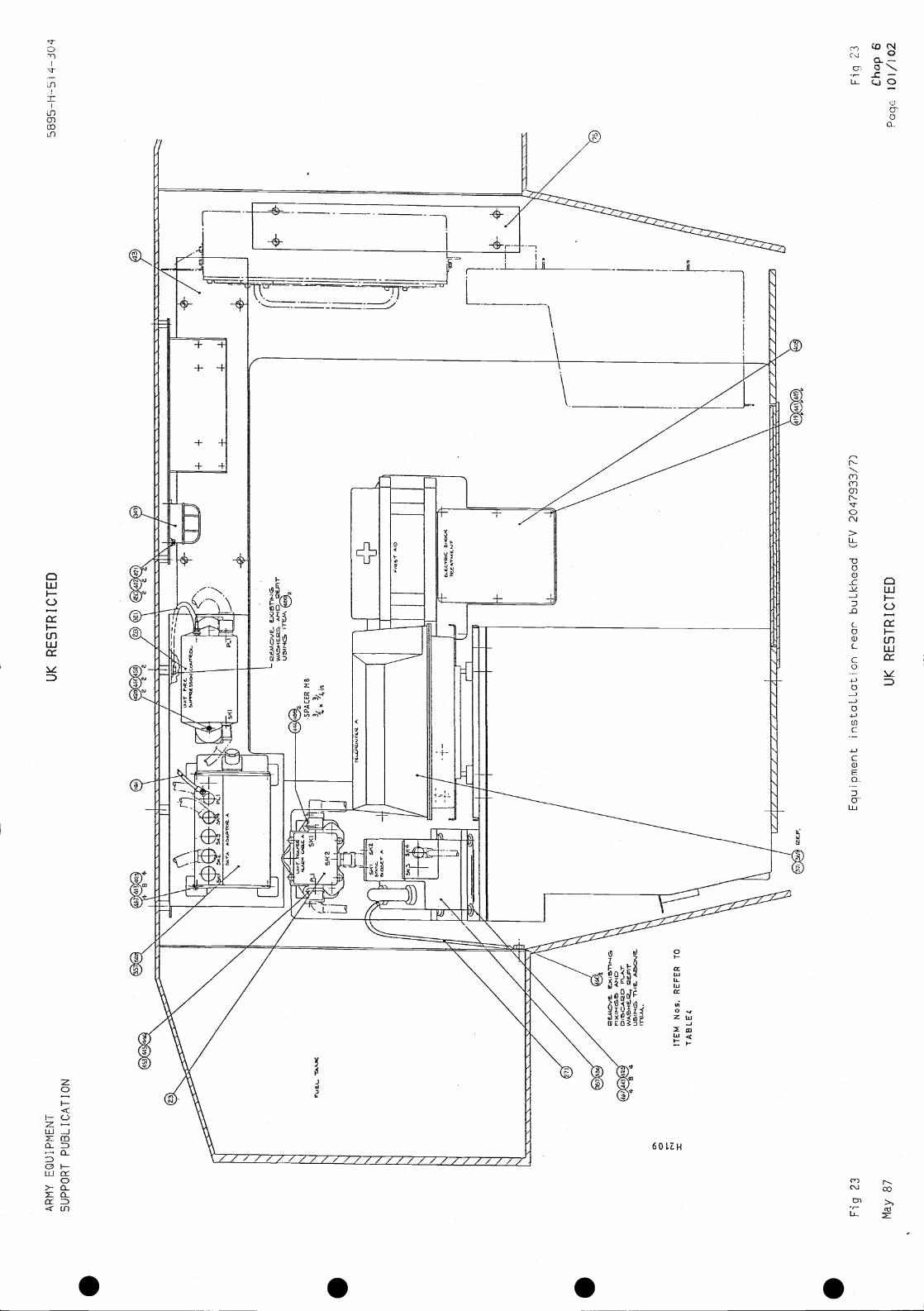
t\RM
Y E
QU
IPM
EN
T
SU
PP
OR
T P
UB
LIC
AT
ION
UK
RE
ST
RIC
TE
D58
95—
H-5
1 4-
304
Equ
ipm
ent i
nsta
LLat
ion
rear
' buL
khea
d C
FV
204
7933
/7)
Cha
p 6
May
87
UK
RE
ST
RIC
TE
DP
aqc.
iOi/1
02
AH
D
ITE
M N
os. R
EF
ER
TO
Fig
23
Fiq
23

. . . .
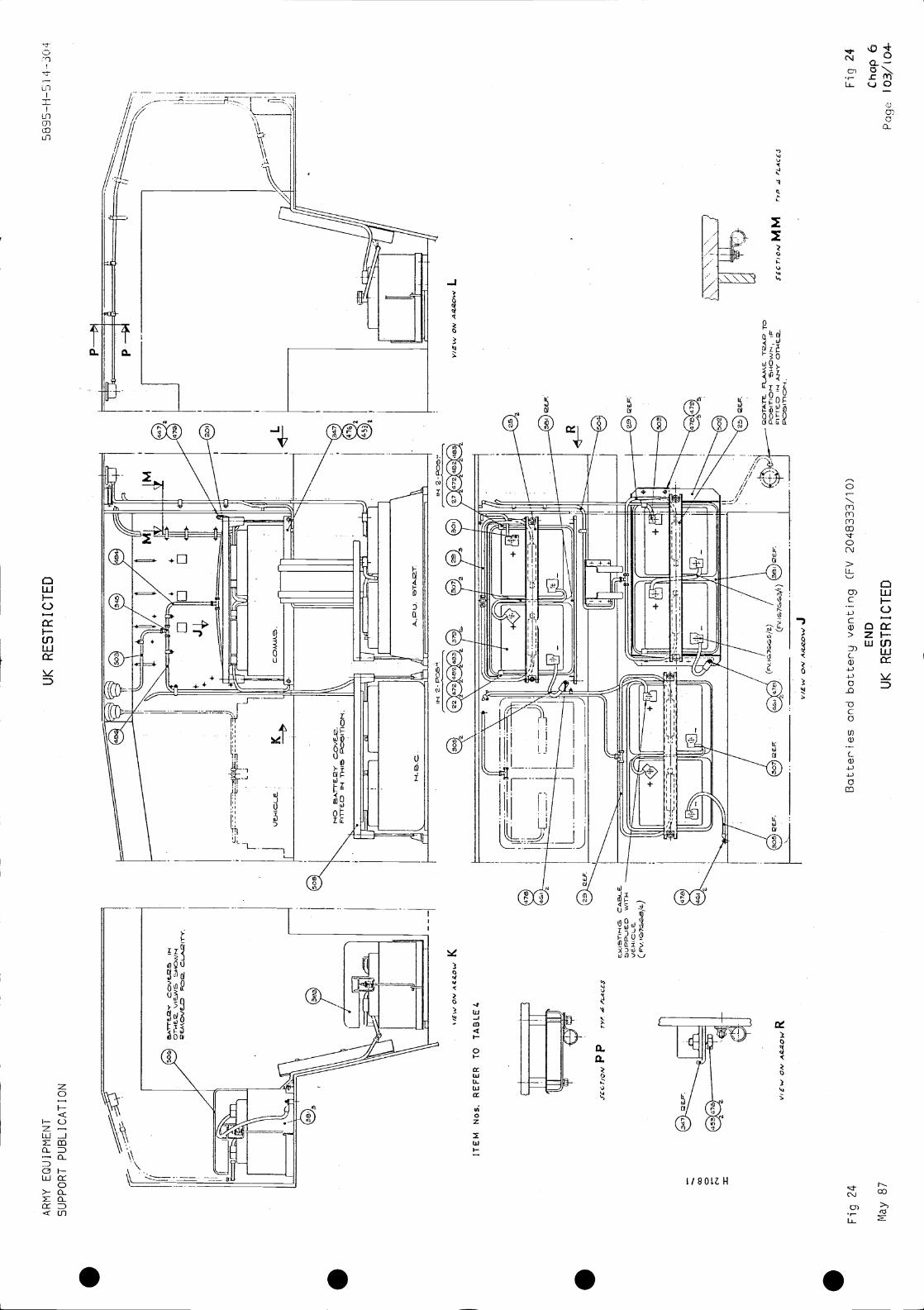
AR
MY
EQ
UIP
ME
NT
SU
PP
OR
T P
UB
LIC
AT
ION
UK
RE
ST
RIC
TE
D58
95—
H—
5 I
'4-J
04
ITE
M N
os. R
EF
ER
TO
TA
BLE
4 4
C
L
Fig
24
May
87
Bat
terie
s an
d ba
ttery
ven
ting
(FV
204
8333
/10)
EN
D
UK
RE
ST
RIC
TE
D
c]r1
€JD
,-i
ON
K
P P
ON
R
VIE
W O
NJ
MM
fvp
4 'L
.Ace
J
Fig
24
Cho
p a
Pag
e 10
3/(0
4

S S S S

ARMY EQU I PMENT UK RESTRICTED 5895-H-51 4-304SUPPORT PUBLICATION
Chapter 7
INSTALLATION CHECKOUT AND TEST PROCEDURES
CONTENTS
Para1 Introduction3 Tools and equipment4 Bonding tests5 Preliminary preparation6 Installation equipment and cable checks7 Imported power checks8 Generator fuel/oil checks9 Subscriber loop checks
10 Equipment setting-up procedures11 APU fire suppression checks (WARNING)12 Generator functional checks13 Teleprinter link checks14 Central alarm panel checks
Power suppliesComms alarm modulesPower alarm modulesBattery status module
15 CLANSMAN harness checks16 Vehicle fire alarm checks17 FAX tests18 Continuity tests19 APU fire extinguisher21 APU fire extinguisher inspection28 APU fire extinguisher initiator cartridge functional checks (WARNINGS)
Table Page1 Test configuration for Patch Panel pin location 11
2 LASE programme of LDA Multiplexer channels 12
3 LASE programme of ULSIE channels 13
4 Test configuration for Patch Panel pin location 145 ULS channel testing 156 Civil channel testing 15
7 Calling from the ULS to a sub-set 168 Civil loop to sub-set 16
Fig Page1 D.C. Power cable routeing diagram 17/182 Signal cable routeing diagram 19/203 Test box circuit diagram 214 APU fire extinguisher operating head 225 APU fire extinguisher 24
Annex A Earth bonding tests - results sheets
Chap 7Sep 00 (Amdt 2) UK RESTRICTED Page 1
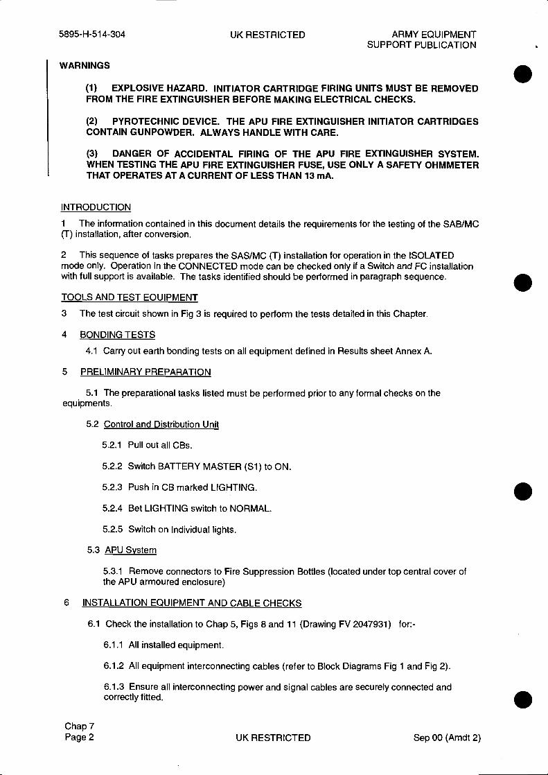
5895-H-514-304 UK RESTRICTED ARMY EQUIPMENTSUPPORT PUBLICATION
WARNINGS
(1) EXPLOSIVE HAZARD. INITIATOR CARTRIDGE FIRING UNITS MUST BE REMOVEDFROM THE FIRE EXTINGUISHER BEFORE MAKING ELECTRICAL CHECKS.
(2) PYROTECHNIC DEVICE. THE APU FIRE EXTINGUISHER INITIATOR CARTRIDGESCONTAIN GUNPOWDER. ALWAYS HANDLE WITH CARE.
(3) DANGER OF ACCIDENTAL FIRING OF THE APU FIRE EXTINGUISHER SYSTEM.WHEN TESTING THE APU FIRE EXTINGUISHER FUSE, USE ONLY A SAFETY OHMMETERTHAT OPERATES AT A CURRENT OF LESS THAN 13 mA.
INTRODUCTION
1 The information contained in this document details the requirements for the testing of the SAB/MC(T) installation, after conversion.
2 This sequence of tasks prepares the SAS/MC (T) installation for operation in the ISOLATEDmode only. Operation in the CONNECTED mode can be checked only if a Switch and FC installationwith full support is available. The tasks identified should be performed in paragraph sequence.
TOOLS AND TEST EOUIPMENT
3 The test circuit shown in Fig 3 is required to perform the tests detailed in this Chapter.
4 BONDING TESTS
4.1 Carry out earth bonding tests on all equipment defined in Results sheet Annex A.
5 PRELIMINARY PREPARATION
5.1 The preparational tasks listed must be performed prior to any formal checks on theequipments.
5.2 Control and Distribution Unit
5.2.1 Pull out all CBs.
5.2.2 Switch BATTERY MASTER (Si) to ON.
5.2.3 Push in CB marked LiGHTING.
5.2.4 Bet LIGHTING switch to NORMAL.
5.2.5 Switch on Individual lights.
5.3 APU System
5.3.1 Remove connectors to Fire Suppression Bottles (located under top central cover ofthe APU armoured enclosure)
6 INSTALLATION EQUIPMENT AND CABLE CHECKS
6.1 Check the installation to Chap 5, Figs 8 and 11 (Drawing FV 2047931) for:-
6.1.1 All installed equipment.
6.1.2 All equipment interconnecting cables (refer to Block Diagrams Fig 1 and Fig 2).
6.1.3 Ensure all interconnecting power and signal cables are securely connected andcorrectly fitted.
Chap 7Page 2 UK RESTRICTED Sep 00 (Amdt 2)

ARMY EQUIPMENT UK RESTRICTED 5895-H-514-304SUPPORT PUBLICATION
7 IMPORTED POWER CHECKS
7.1 Connect a 28V dc supply to the imported power socket.
7.2 On the Control and Distribution unit switch DC import to ON, lamp should light and ammetershould show current flow.
7.3 Leave connected.
8 GENERATOR FUEL/OIL CHECKS
8.1 Check the generator oil level and replenish if necessary, refer to AESP 6115-0-251.
8.2 Fuel for the generators is provided from the main fuel supply for the vehicle. Ensure that thefuel control valve situated on the RH fuel tank inside the vehicle is in the ON position.
8.3 If the fuel in the tanks is less than ¼ full, then the fuel control valve lever should be set to theRES (reserve) position.
9 SUBSCRIBER LOOP CHECKS
9.1 On Control and Distribution Unit push in CBs for DATA ADAP 'A', DATA ADAP 'B' and forEquipments defined in Para 9.2.
9.2 Switch the LASE, PATCH PANEL, ULS, ULSIE AND LDA MULTIPLEXER to ON.
9.3 Configure the patch panel as per Table 1.
9.4 Programme the LASE as per Table 2.
9.5 Connect a 7 quad cable between the 701 port and the Test Box (Fig 3).
9.6 Connect a Static Subset to the Test Box.
9.7 Carry out a subscriber calling check between the Test Box Subset and an Internal Subset forall 7 positions of the Test Box.
9.8 Move the 7 quad cable to the 702 port, repeat Para 9.7.
9.9 Move the 7 quad cable to the 7Q3 port, repeat Para 9.7.
9.10 Move the 7 quad cable to the 704 port, repeat Para 9.7.
9.11 On Control and Distribution Unit push in CBs - PRINTER 'A' and PRINTER 'B'.
9.12 Carry out Teleprinter link checks as defined in Para 12.
9.13 Reconfigure Patch Panel as per Table 4.
9.14 Move the 7 quad cable to the 7Q5 port, repeat Para 9.7.
9.15 Move the 7 quad cable to the 706 port, repeat Para 9.7.
Chap 7Oct 94 (Amdt 1) UK RESTRICTED Page 3
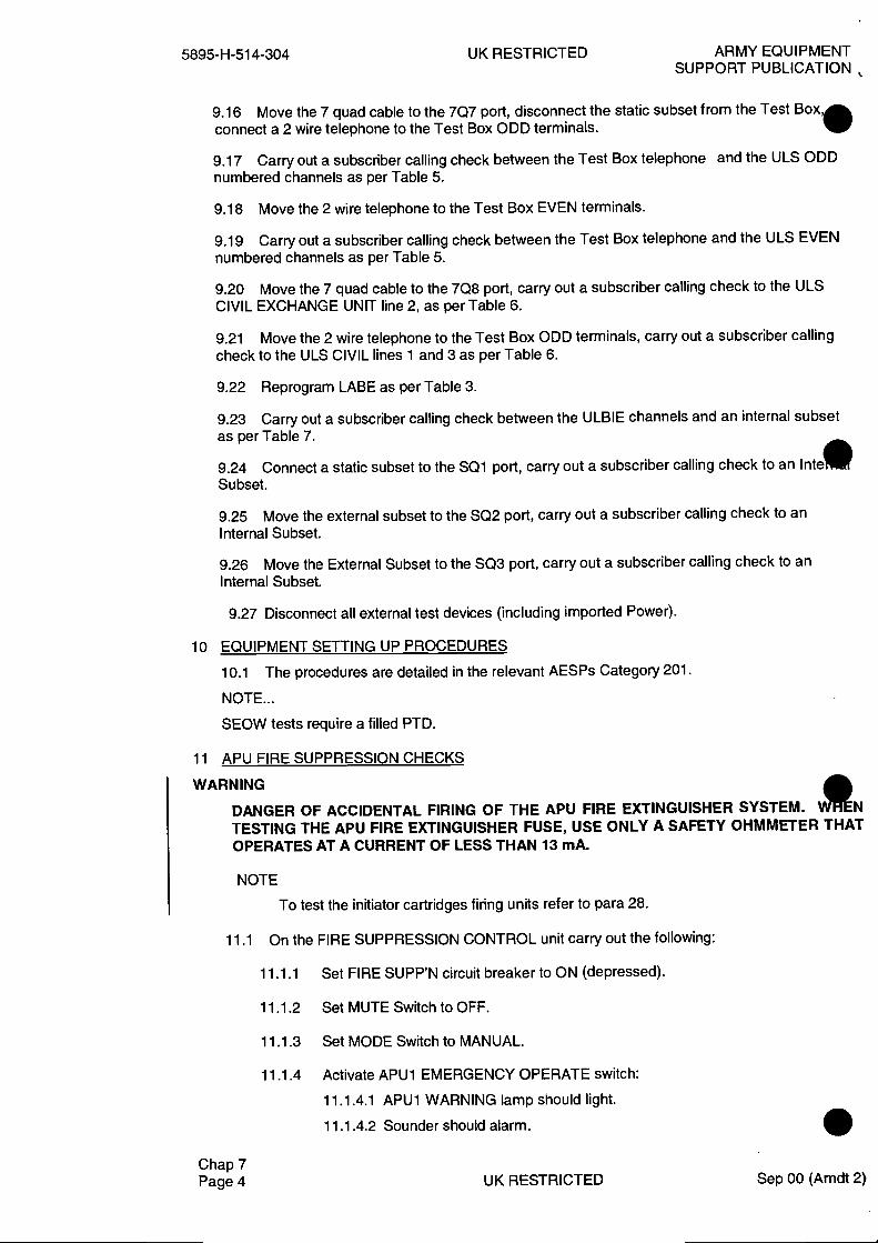
5895-H-514-304 UK RESTRICTED ARMY EQUIPMENTSUPPORT PUBLICATION
9.16 Move the 7 quad cable to the 707 port, disconnect the static subset from the Test Box,connect a 2 wire telephone to the Test Box ODD terminals.
9.17 Carry out a subscriber calling check between the Test Box telephone and the ULS ODDnumbered channels as per Table 5.
9.18 Move the 2 wire telephone to the Test Box EVEN terminals.
9.19 Carry out a subscriber calling check between the Test Box telephone and the ULS EVENnumbered channels as per Table 5.
9.20 Move the 7 quad cable to the 7Q8 port, carry out a subscriber calling check to the ULSCIVIL EXCHANGE UNIT line 2, as per Table 6.
9.21 Move the 2 wire telephone to the Test Box ODD terminals, carry out a subscriber callingcheck to the ULS CIVIL lines 1 and 3 as per Table 6.
9.22 Reprogram LABE as per Table 3.
9.23 Carry out a subscriber calling check between the ULBIE channels and an internal subsetas per Table 7.
9.24 Connect a static subset to the SQl port, carry out a subscriber calling check to an Inte•Subset.
9.25 Move the external subset to the SQ2 port, carry out a subscriber calling check to anInternal Subset.
9.26 Move the External Subset to the SQ3 port, carry out a subscriber calling check to anInternal Subset.
9.27 Disconnect all external test devices (including imported Power).
10 EQUIPMENT SETTING UP PROCEDURES
10.1 The procedures are detailed in the relevant AESPs Category 201.
NOTE...
SEOW tests require a filled PTD.
11 APU FIRE SUPPRESSION CHECKS
WARNING
DANGER OF ACCIDENTAL FIRING OF THE APU FIRE EXTINGUISHER SYSTEM. N
TESTING THE APU FIRE EXTINGUISHER FUSE, USE ONLY A SAFETY OHMMETER THATOPERATES AT A CURRENT OF LESS THAN 13 mA.
NOTE
To test the initiator cartridges firing units refer to para 28.
11.1 On the FIRE SUPPRESSION CONTROL unit carry out the following:
11.1.1 Set FIRE SUPP'N circuit breaker to ON (depressed).
11.1.2 Set MUTE Switch to OFF.
11.1.3 Set MODE Switch to MANUAL.
11.1.4 Activate APU1 EMERGENCY OPERATE switch:
11.1.4.1 APU1 WARNING lamp should light.
11.1.4.2 Sounder should alarm.
Chap 7Page 4 UK RESTRICTED Sep 00 (Amdt 2)

ARMY EQUIPMENT UK RESTRICTED 5895-H-514-304SUPPORT PUBLICATION
11.1.4.3 APU1 WARNING lamp on the FIRE SUPPRESSIONREMOTE unit should light.
11.1.4.4 Supply voltage 28V dc should appear at APU1free connector defined in Para. 5.3.1 (A + ye, B - ye).
11.1.5 De—actjvate AP(J1 EMERGENCY OPERATE switch - supply voltsshould disappear.
11.1.6 Repeat paras 11.1.3 and 11.1.4 for APU2.
11.1.7 Switch to TEST APU1, APU1 lamp should light:
Sounder should alarmAPU1 lamp on FIRE REMOTE unit should light.
11.1.8 Switch to TEST APU2, APU2 lamp should light:
Sounder should alarmAPU2 lamp on FIRE REMOTE unit should light.
GENERATOR FUNCTIONAL CHECKS
12 On the DC Distribution and Control Panel carry out the following:-
12.1 Ensure the chassis earth is connected.
12.2 Ensure BATTERY MASTER (Si) is ON.
12.3 Ensure CHARGING SOURCE (S2) is to APIJ.
12.4 Put all other switches to OFF and POWER SYSTEM to APU1.
12.5 Set FUEL SOL1, FUEL SOL2, FIRE SUPP'N and FUEL PUMP circuitbreakers to ON (depressed)
12.6 Set APU1 and APU2 OFF/COLD START switches to COLD START.
12.7 Switch APU1 (S9) and APU2 (S].3) to ON. APU1 SELECTED lamp is lit.
12.8 Set START SELECT SWITCH (S19) to APU1.
12.9 Switch APU1 STOP/START (Sil) to START, generator should start(Release Switch).
12.10 Switch APU1 EXCITE/OFF/LOAD (SlO) to EXCITE then LOAD APUI, LOAD ONLamp should light. With AMMETER SELECTOR switch to INPUT, meter showscurrent flow.
12.11 Set APU1 OFF/COLD START switch to OFF.
12.12 Switch START SELECT (S19) to APU2.
12.13 Switch APU2 STOP/START (S12) to START, second generator shouldstart (Release Switch).
12.14 Switch APU2 EXCITE/OFF/LOAD (S14) to EXCITE then LOAD APU2, LOAD ONlamp should light and ammeter shows current flow.
Chap 7Oct 94 (Amdt 1) UK RESTRICTED Page 5
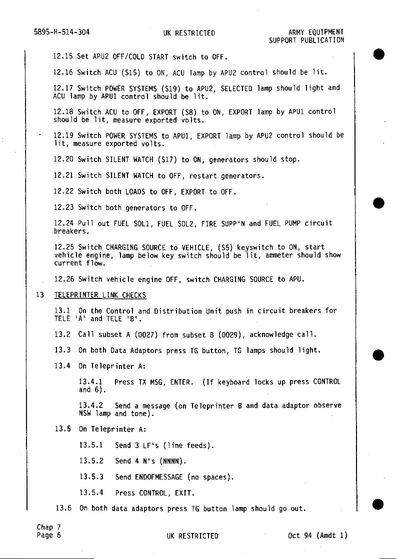
5895-H-514-304 UK RESTRICTED ARMY EQUIPMENTSUPPORT PUBLICATION
12.15 Set APU2 OFF/COLD START switch to OFF.
12.16 Switch ACU (515) to ON, ACU lamp by APU2 control should be lit.
12.17 Switch POWER SYSTEMS (sig) to APU2, SELECTED lamp should light andACU lamp by APU1 control should be lit.
12.18 Switch ACU to OFF, EXPORT (S8) to ON, EXPORT tamp by APU1 controlshould be lit, measure exported volts.
12.19 Switch POWER SYSTEMS to APU1, EXPORT lamp by APU2 control should belit, measure exported volts.
12.20 Switch SILENT WATCH (S17) to ON, generators should stop.
12.21 Switch SILENT WATCH to OFF, restart generators.
12.22 Switch both LOADS to OFF, EXPORT to OFF.
12.23 Switch both generators to OFF.
12.24 Pull out FUEL SOL1, FUEL SOL2, FIRE SUPP'N and FUEL PUMP circuitbreakers.
12.25 Switch CHARGING SOURCE to VEHICLE, (S5) keyswitch to ON, startvehicle engine, lamp below key switch should be lit, ammeter should showcurrent flow.
12.26 Switch vehicle engine OFF, switch CHARGING SOURCE to APU.
13 TELEPRINTER LINK CHECKS
13.1 On the Control and Distribution Unit push in circuit breakers forTELE 'A' and TELE 'B'.
13.2 Call subset A (0027) from subset B (0029), acknowledge call.
13.3 On both Data Adaptors press TG button, TG lamps should light.
13.4 On Teleprinter A:
13.4.1 Press TX ENTER. (If keyboard locks up press CONTROLand 6).
13.4.2 Send a message (on Teleprinter B and data adaptor observeNSW lamp and tone).
13.5 On Teleprinter A:
13.5.1 Send 3 LF's (line feeds).
13.5.2 Send 4 N's (NNNN).
13.5.3 Send ENDOFMESSAGE (no spaces).
13.5.4 Press CONTROL, EXIT.
13.6 On both data adaptors press TG button lamp should go out.
Chap 7Page 6 UK RESTRICTED Oct 94 (Amdt 1)
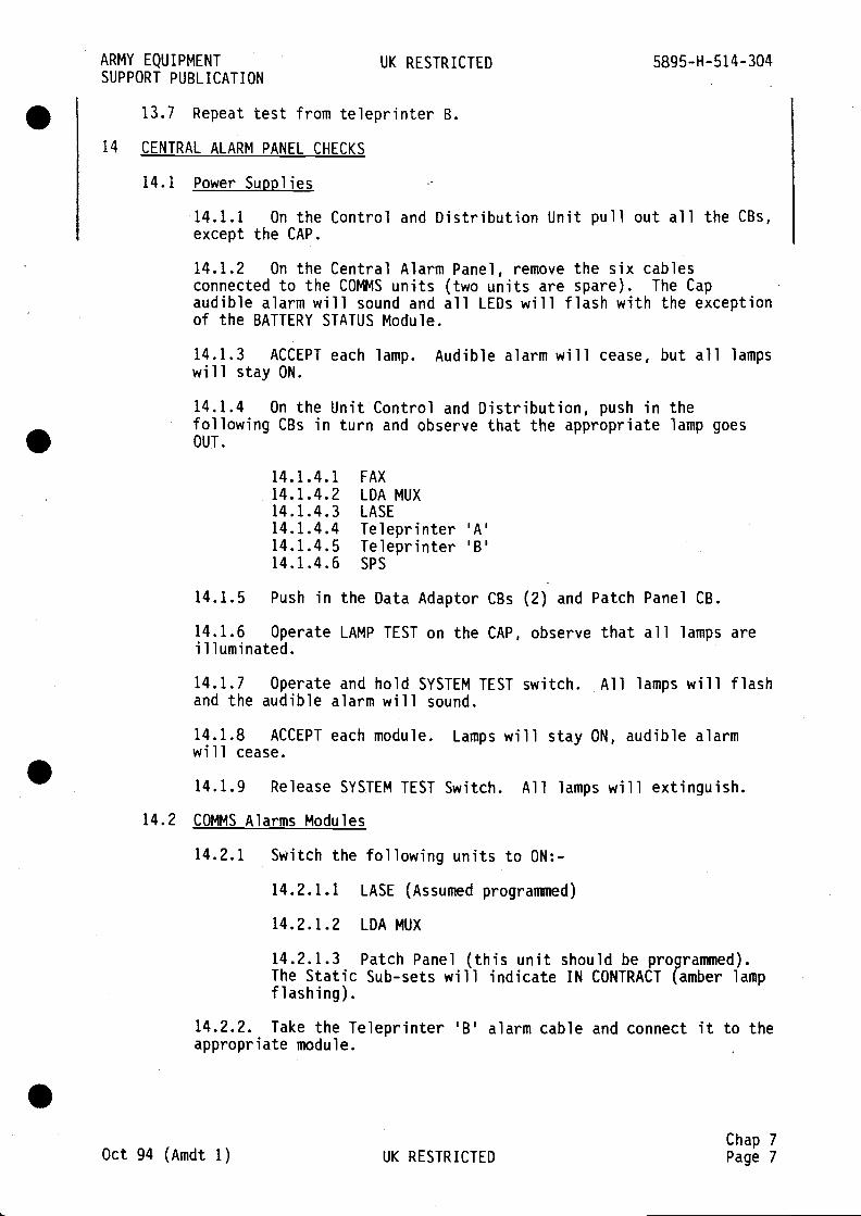
ARMY EQUIPMENT UK RESTRICTED 5895-H-514-304SUPPORT PUBLICATION
13.7 Repeat test from teleprinter B.
14 CENTRAL ALARM PANEL CHECKS
14.1 Power Supplies
14.1.1 On the Control and Distribution Unit pull out all the CBs,except the CAP.
14.1.2 On the Central Alarm Panel, remove the six cablesconnected to the COMMS units (two units are spare). The Capaudible alarm will sound and all LEDs wfll flash with the exceptionof the BATTERY STATUS Module.
14.1.3 ACCEPT each lamp. Audible alarm will cease, but all lampswill stay ON.
14.1.4 On the Unit Control and Distribution, push in thefollowing CBs in turn and observe that the appropriate lamp goesOUT.
14.1.4.1 FAX14.1.4.2 LDA MUX14.1.4.3 LASE14.1.4.4 Teleprinter 'A'14.1.4.5 Teleprinter 'B'14.1.4.6 SPS
14.1.5 Push in the Data Adaptor CBs (2) and Patch Panel CB.
14.1.6 Operate LAMP TEST on the CAP, observe that all lamps areilluminated.
14.1.7 Operate and hold SYSTEM TEST switch. All lamps will flashand the audible alarm will sound.
14.1.8 ACCEPT each module. Lamps will stay ON, audible alarmwill cease.
14.1.9 Release SYSTEM TEST Switch. All lamps will extinguish.
14.2 COMMS Alarms Modules
14.2.1 Switch the following units to ON:-
14.2.1.1 LASE (Assumed progranDned)
14.2.1.2 LDA MUX
14.2.1.3 Patch Panel (this unit should be programmed).The Static Sub-sets will indicate IN CONTRACT (amber lampflashing).
14.2.2. Take the Teleprinter 'B' alarm cable and connect it to theappropriate module.
Chap 7Oct 94 (Amdt 1) UK RESTRICTED Page 7

5895-H-514-304 UK RESTRICTED ARMY EQUIPMENTSUPPORT PUBLICATION
14.2.3 Switch Teleprinter 'B' to ON. The teleprinter willinitiate an alarm by self test. The alarm will be routed throughthe CAP which will give an audible Alarm and the COMMS module lightwill flash. Do not ACCEPT. The Teleprinter will enter its ownsearch sequence and will determine if there is rio fault and cancelthe CAP alarms.
14.2.4 Switch the Teleprinter OFF.
14.2.5 Repeat the sequence above for the remaining five COMMSmodules.
14.2.6 Momentarily apply a short circuit between pins C and A ofthe connector for each of the six modules. The module should alarmwhile this is held.
14.2.7 Reconnect COMMS cables to their respective modules (thereare two spare modules not connected).
14.2.8 Ensure the LDA MUX is ON and switch the LASE to OFF. Thiswill precipitate an LDA alarm.
14.2.9 Switch the LASE to ON and operate the LASE test button.This will initiate a LASE alarm and is part of the BITE sequence.
14.2.10 Switch both Teleprinters to ON. An alarm signal will beinitated as part of the self test sequence.
14.2.11 Switch the SPS to ON. An alarm signal will be initiatedas part of the self test sequence.
14.2.12 Switch on the FAX. The alarm is part of the self testsequence.
14.3 Power Alarm Modules
14.3.1 On the Control and Distribution Unit at position POWER APU1, set the ON-OFF switch to ON, the APU1 FAlL lamp will illuminate.On the CAP, the POWER module for APU1 will initiate an audiblea arm and the lamp will flash.
14.3.2 Accept the alarm. The audible alarm will cease, but thelamp will stay ON.
14.3.3 On the Control and Distribution Unit press the START APU1;when the generator runs, switch to EXCITE; then to LOAD ON. LOAD
ON lamp will illuminate (on the Control and Distribution Unit). As
the generator gives an output, the two FAIL lamps, one on the CAPand one on the Control and Distribution Unit will both extinguish.
14.3.4 Repeat the above sequence for APU2.
14.4 Battery Status Module
14.4.1 out all CBs with the exception of the CAP.
14.4.2 Using a 5A variable PSU (OV - 30V set at 28V) apply as forDC import checks.
Chap 7Page 8 UK RESTRICTED Oct 94 (Amdt 1)
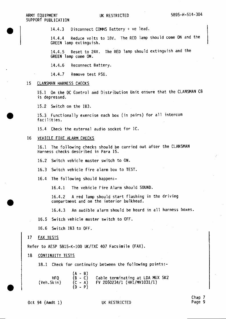
ARMY EQUIPMENT UK RESTRICTED 5895-H-514-304SUPPORT PUBLICATION
14.4.3 Disconnect COMMS Battery + ye lead.
14.4.4 Reduce volts to 18V. The RED lamp should come ON and theGREEN lamp extinguish.
14.4.5 Reset to 24V. The RED lamp should extinguish and theGREEN lamp come ON.
14.4.6 Reconnect Battery.
14.4.7 Remove test PSU.
15 CLANSMAN HARNESS CHECKS
15.1 On the DC Control and Distribution Unit ensure that the CLANSMAN CB
is depressed.
15.2 Switch on the 183.
15.3 Functionally exercise each box (in pairs) for all intercomfacilities.
15.4 Check the external audio socket for IC.
16 VEHICLE FIRE ALARM CHECKS
16.1 The following checks should be carried out after the CLANSMANHarness checks described in Para 15.
16.2 Switch vehicle master switch to ON.
16.3 Switch vehicle fire alarm box to TEST.
16.4 The following should happen:-
16.4.1 The vehicle Fire Alarm should SOUND.
16.4.2 A red lamp should start flashing in the drivingcompartment and on the interior bulkhead.
16.4.3 An audible alarm should be heard in all harness boxes.
16.5 Switch vehicle master switch to OFF.
16.6 Switch 183 to OFF.
17 FAX TESTS
Refer to AESP 5815-K-100 UK/TXC 407 Facsimile (FAX).
18 CONTINUITY TESTS
18.1 Check for continuity between the following points:-
(A - B)HFQ (B - C) Cable terminating at LDA MUX SK2
(Veh.Skin) (C - A) FV 2050234/1 (HH1/MV1O31/1)(D - P)
Chap 7Oct 94 (Amdt 1) UK RESTRICTED Page 9

5895-H-514-304 UK RESTRICTED ARMY EQUIPMENTSUPPORT PUBLICATION
18.2 Insert pin into Patch Panel Matrix PKT LK - INTERPACKET TRUNK 1,
check for continuity between the following points:-
(B - h)SQ4 (Bl - i) Cable terminating at SPS SKG
(Veh.Skin) (A - f) FV 2050229/2 (HH1/MV1026/4C)(Al - g)
18.3 Insert pin into Patch Panel Matrix PKT LK - INTERPACKET TRUNK 2,
check for continuity between the following points:-
(B -h)SQ4 (Bi - i) Cable terminating at SPS SKH
(Veh.Skin) (A - f) FV 2050229/1 (HH1/MV1026/3C)(Al - g)
.
.
.Chap7Page 10 UK RESTRICTED Oct 94 (Amdt 1)
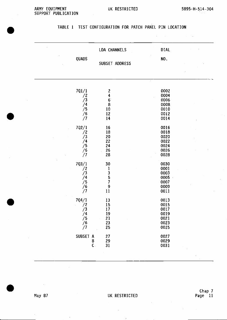
ARMY EQUIPMENT UK RESTRICTED 5895-H-514-304SUPPORT PUBLICATION
TABLE 1 TEST CONFIGURATION FOR PATCH PANEL PIN LOCATION
LDA CHANNELS DIAL
QUADS NO.SUBSET ADDRESS
7Q1/1 2 0002/2 4 0004/3 6 0006/4 8 0008/5 10 0010/6 12 0012/7 14 0014
7Q2/1 16 0016/2 18 0018/3 20 0020/4 22 0022/5 24 0024/6 26 0026/7 0028
7Q3/1 30 0030/2 1 0001/3 3 0003/4 5 0005/5 7 0007/6 9 0009/7 11 0011
7Q4/1 13 0013/2 15 0015/3 17 0017/4 19 0019/5 21 0021/6 23 0023/7 25 0025
SUBSET A 27 0027B 29 0029C 31 0031
Chap 7May 87 UK RESTRICTED Page 11
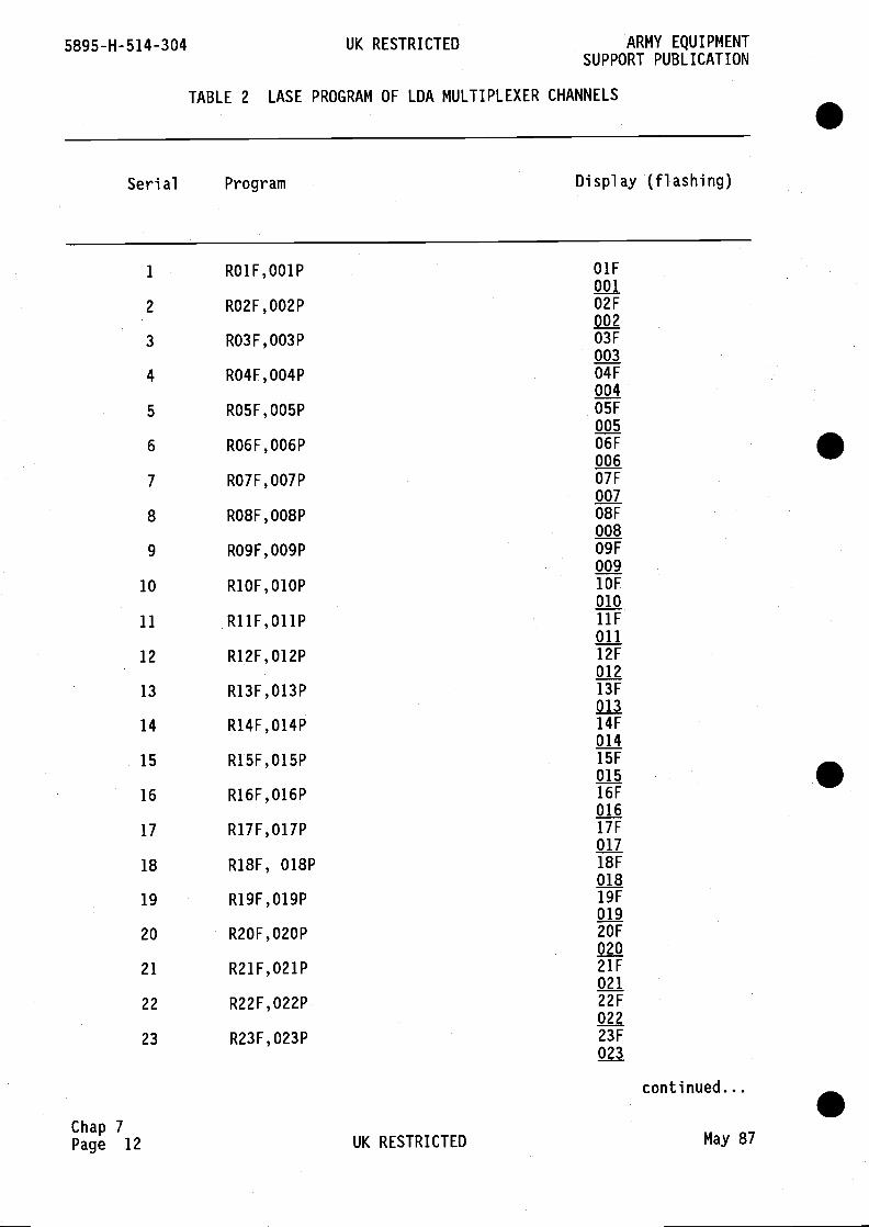
5895-H-514-304 UK RESTRICTED ARMY EQUIPMENTSUPPORT PUBLICATION
TABLE 2 LASE PROGRAM OF LDA MULTIPLEXER CHANNELS .Serial Program Display (flashing)
1 RO1F,001P O1F001
2 RO2F,002P 02F002
3 RO3F,003P 03F003
4 RO4F,004P 04F004
5 RO5F,005P 05F005
6 RO6F,006P 06F006
7 RO7F,007P 07F007
8 RO8F,008P 08F008
9 RO9F,009P 09F009
10 R1OF,O1OP 1OF
01011 R11F,O11P hF
01112 R12F,012P 12F
01213 R13F,013P 13F
01314 R14F,014P 14F
01415 R15F,015P 15F
01516 R16F,016P 16F
01617 R17F,017P 17F
01718 R18F, 018P 18F
01819 R19F,019P 19F
01920 R2OF,020P 20F
02021 R21F,021P 21F
021
22 R22F,022P 22F022
23 R23F,023P 23F023
continued...
Chap 7Page 12 UK RESTRICTED May 87
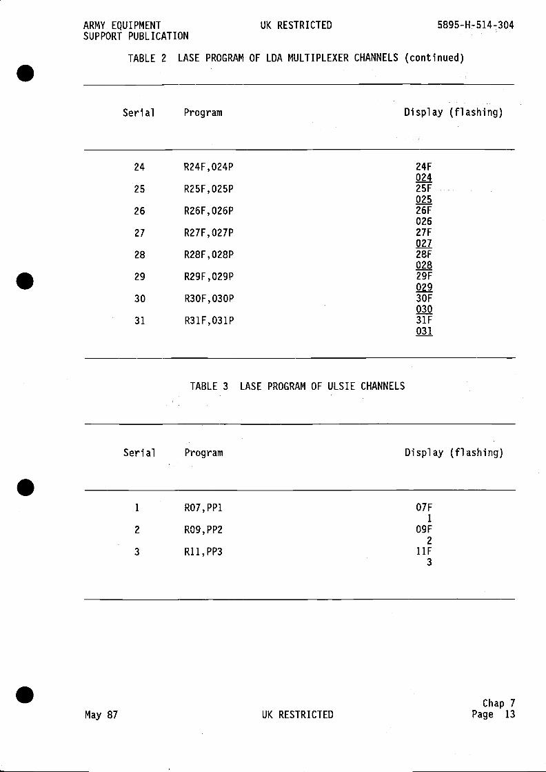
ARMY EQUIPMENT UK RESTRICTED 5895-H-514-304SUPPORT PUBLICATION
TABLE 2 LASE PROGRAM OF LDA MULTIPLEXER CHANNELS (continued)
Serial Program Display (flashing)
24 R24F,024P 24F024
25 R25F,O25P 25F025
26 R26F,026P 26F026
27 R27F,027P 27F027
28 R28F,028P 28F028
29 R29F,029P 29F029
30 R3OF,030P 30F030
31 R31F,031P 31F031
TABLE 3 LASE PROGRAM OF ULSIE CHANNELS
Serial Program Display (flashing)
1 RO7,PP1 07F1
2 R09,PP2 09F2
3 R11,PP3 hF3
Chap 7May 87 UK RESTRICTED Page 13
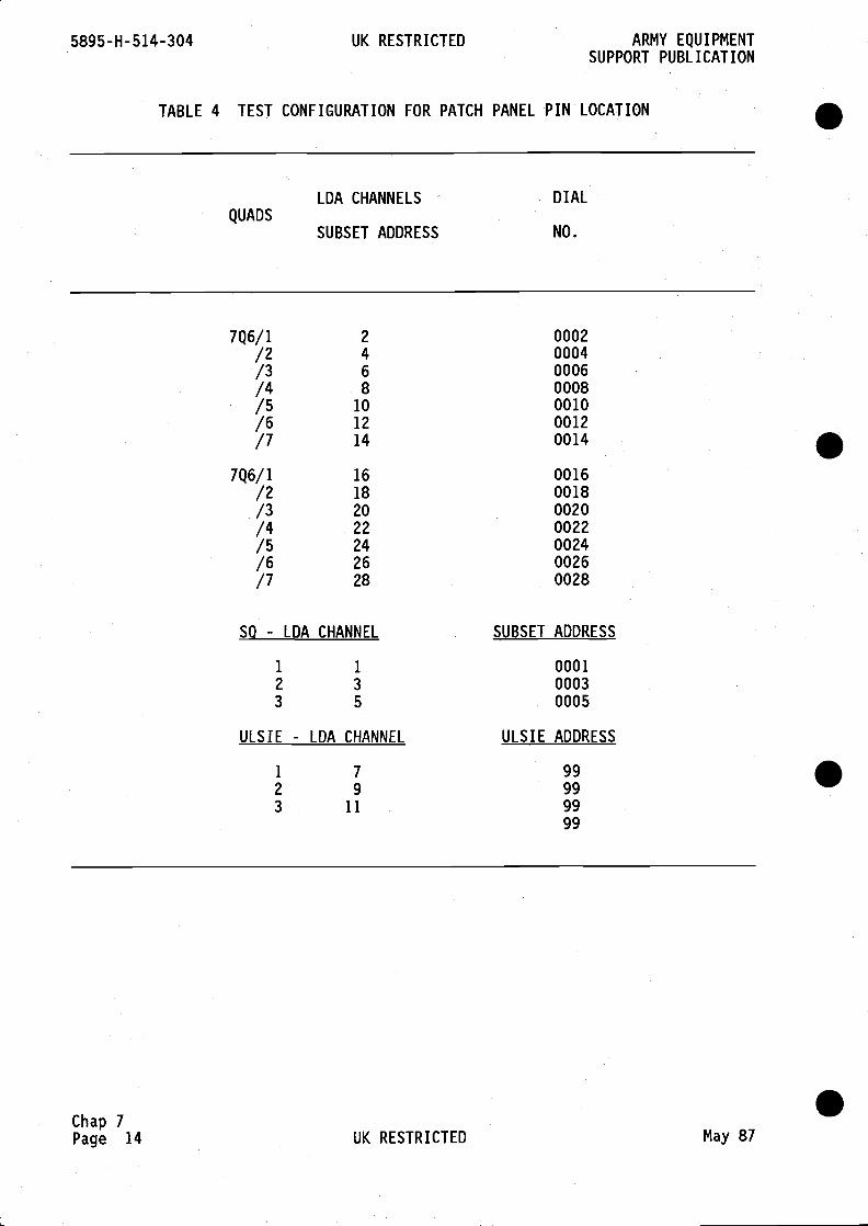
5895-H- 514-304 UK RESTRICTED ARMY EQUIPMENTSUPPORT PUBLICATION
TABLE 4 TEST CONFIGURATION FOR PATCH PANEL PIN LOCATION
QUADS
LDA CHANNELS
SUBSET ADDRESS
DIAL
NO.
7Q6/1 2 0002/2 4 0004/3 6 0006/4 8 0008/5 10 0010/6 12 0012/7 14 0014
7Q6/1 16 0016/2 18 0018/3 20 0020/4 22 0022/5 24 0024/6 26 0026/7 28 0028
SO - LDA
1
2
3
CHANNEL
1
3
5
SUBSET ADDRESS
000100030005
ULSIE - IDA CHANNEL ULSIE ADDRESS
1 7 992 9 993 11 99
99
.
.
.
Chap 7Page 14 UK RESTRICTED May 87
.

ARMY EQUIPMENT UK RESTRICTED 5895-H-514-304SUPPORT PUBLICATION
TABLE 5 ULS CHANNEL TESTING (Test Box - Fig 3)
Serial Test Box
(Switch Position)
ULS Channel
1 1 ODD terminals 1
2 2 3
3 3 5
4 4 7
5 5 9
6 6 11
7 7 13
8 1 EVEN terminals 2
9 2 4
10 3 6
11 4 812 5 1013 6 12
TABLE 6 CIVIL CHANNEL TESTING
Serial Test Box Civil Channel Remarks
(Switch position)
1 1 EVEN terminals 2 Ring in fromlinesman phone, ULSoperator holds down
2 1 ODD terminals 1 SPEAK key and talks.
3 2 ODD terminals 3
Chap 7May 87 UK RESTRICTED Page 15
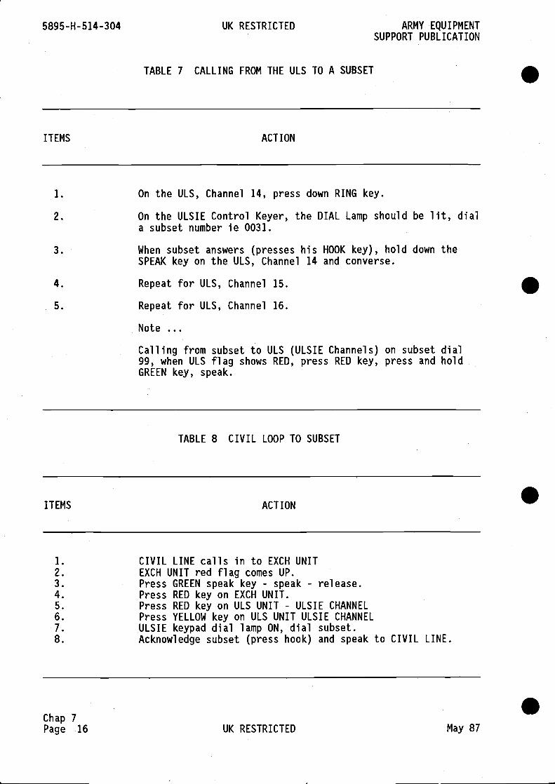
5895-H- 514-304 UK RESTRICTED ARMY EQUIPMENTSUPPORT PUBLICATION
TABLE 7 CALLING FROM THE ULS TO A SUBSET
Chap 7Page 16 UK RESTRICTED May 87
.
.
.
ITEMS ACTION
1. On the ULS, Channel 14, press down RING key.
2. On the ULSIE Control Keyer, the DIAL Lamp should be lit, diala subset number le 0031.
3. When subset answers (presses his HOOK key), hold down theSPEAK key on the ULS, Channel 14 and converse.
4. Repeat for ULS, Channel 15.
5. Repeat for ULS, Channel 16.
Note
Calling from subset to ULS (ULSIE Channels) on subset dial99, when ULS flag shows RED, press RED key, press and holdGREEN key, speak.
TABLE 8 CIVIL LOOP TO SUBSET
ITEMS ACTION
1. CIVIL LINE calls in to EXCH UNIT2. EXCH UNIT red flag comes UP.3. Press GREEN speak key - speak - release.4. Press RED key on EXCH UNIT.5. Press RED key on ULS UNIT - ULSIE CHANNEL6. Press YELLOW key on ULS UNIT ULSIE CHANNEL7. ULSIE keypad dial lamp ON, dial subset.8. Acknowledge subset (press hook) and speak to CIVIL LINE.
.
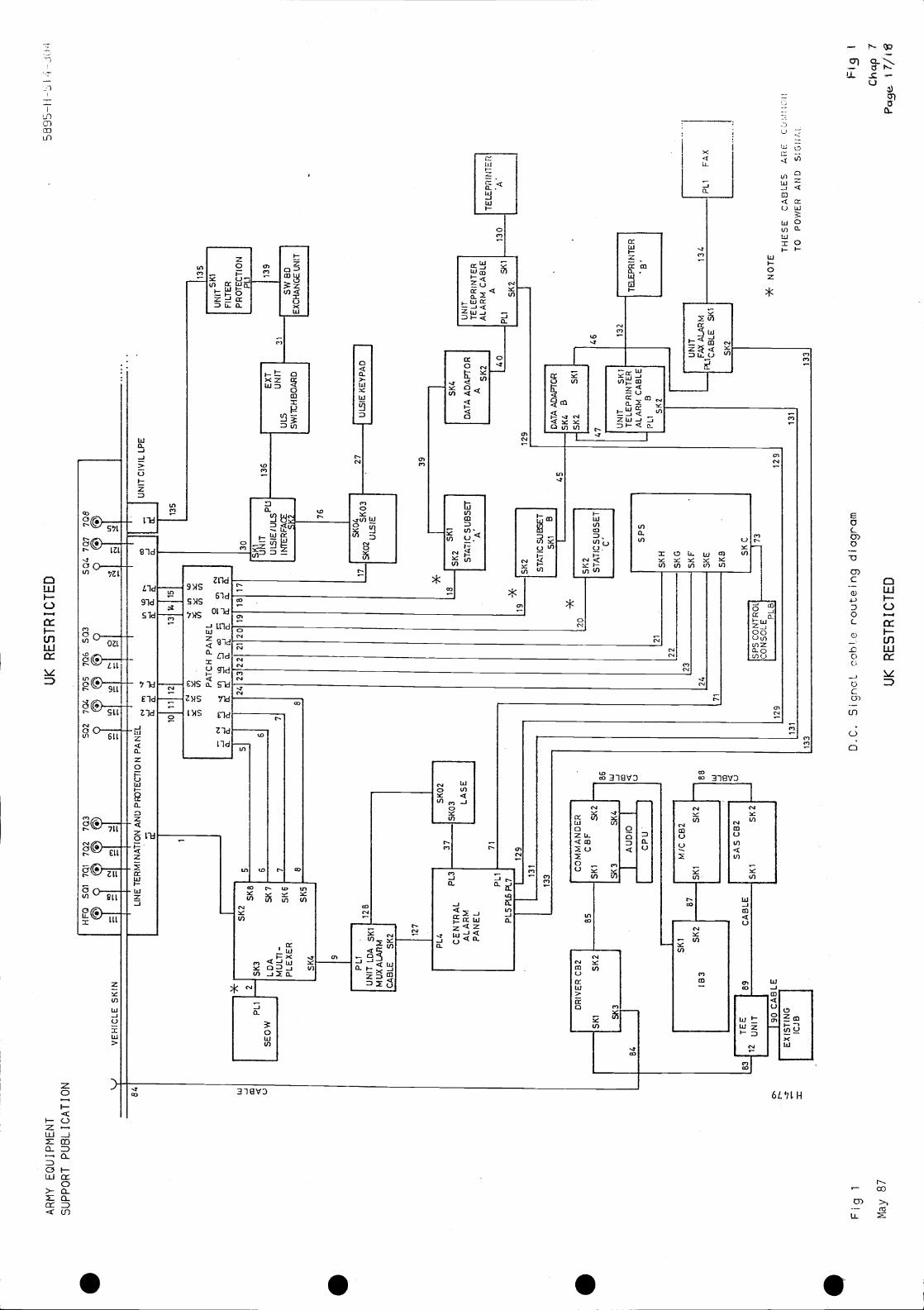
AR
MY
EQ
UIP
ME
NT
UK RESTRICTED
5895
—H
-SI
SU
PP
OR
T P
UB
LIC
AT
ION
Fig
1
May
87
86 Ui -j m 4 U
Ski
87SK
2
M/C
CB
2
____
____
___I
I—i
SA
SC
B2
UC
AB
LE
____
H
Ski
Sk2
SQ
270
4 70
550
3
ID
AT
A A
DA
PT
OR
ISK
4B
SK
ZS
ki
47
I1U
NIT
TE
LEP
RIN
TE
RA
LAR
M C
AB
LEP
L1B
SK
2
IUNIT
FM
ALA
RM S
ki
SK
2
"'
VE
HIC
LE S
KIN
HF
QS
Ql 7
Q1
702
703
II
I
II
II
10ii
12
Lfl
1.0
_jcj
_a.
1* 12P
L1
SE
OW
-J
1311
4115
1
UN
IT C
I V IL
LP
E
5
135
6
.-4(
.)U
)V)(
/) PA
TC
H P
AN
EL .—
1.0
0'l
SK
2S
K8
SK
3
LDA
SK
7M
ULT
I -S
K 6
PLE
XE
R
S K
5S
K4
7
5]
6
24
8
21 2
019
1817
7
8
UN
IT L
DA
MU
XA
LAflM
CA
BLE
SK
2 127
i35
I IF
ILT
ER
IPROTECTION
301
PL1
I
I
I
UN
ITI
sweD
ULS
76
____
____
____
____
__
!!_SKO2
SK
O3
SK
0427
ULSIE
KE
YP
AD
LSIE
J
39
SKO2
I
LASE
71
PL4 C
EN
TR
AL
PL3
ALARM
PANEL
PL1
PL5
PI&
PL7
23 22
23
24
129
131
133
DR
IVE
R C
B2
CO
MM
AN
DE
RI
85C
BF
Ski
5k2
SKI
Sk2
51(3
SK4
84
AU
DIO
CP
UJ
Sk4
TELEPRINTER
MA
CA
DA
TA
AD
AP
TO
R
PLI
5K2
Ski
129
I B3
*
SU
OS
ET
SP
5
2i
SK
H
5KG
SK
F
SK
E
5KB 5K
C
129
22
831
TEE
189
i2U
NIT J9
0CABLE
ICJB
71
46 132
129
131
133
131
136 T
HE
SE
CA
BLE
S A
RE
TO
PO
WE
R A
ND
* N
OT
E
D.C
. Sig
ncL
cobl
.e r
'out
eing
diagram
UK
RESTRICTED
133
I
Cha
p7

. S S S
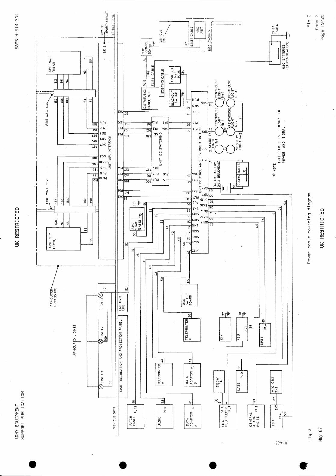
AR
MY
EQ
UIP
ME
NT
UK RESTRICTED
5895
—H
—51
4—
304
SU
PP
OR
T P
UB
LIC
AT
ION
H
PA
NE
LP
L13
ULS
IE
PL
1
CE
NT
RA
LA
LAR
MP
AN
EL
PL2
IU
NIT
CIV
ILLP
E
182
190
0N
CO
52 -fB
AT
TS
175
I;
Power cabLe routeing diagram
UK RESTRICTED
DIS
TR
IBU
TIO
N P
L16
PA
NE
L N
o617
6
EX
IST
CA
BL
EX
IST
ING
CA
BLE
BLA
CK
OU
TLI
NK
BO
XS
WIT
CH
NoI
169
PL2
5
Chap 7
AR
MO
UR
ED
LIG
HT
S
VF
HIC
IF S
KU
'J
LIG
HT
3
I10
8
I 184
Q9 LIGHT2
1109
__-
-IL
--
---
___
FIR
E W
ALL
No2
FIR
E W
Aa
AP
U N
o.2
AP
U N
o.1
(RE
AR
)(F
WD
)14
018
818
714
1
97
____
____
____
____
____
___
______________________
96
95
____
____
____
____
____
___
____
____
____
____
__
94
192
931
105
1041
LIN
E T
ER
MIN
AT
ION
AN
D P
RO
TE
CT
ION
PA
NE
L.
110
16
185
183
rrC
o
52
181
UI
C'I
Co
Co
Co
189
01 Co
9 C
o9
Co
r—01
UI
01
1/)
UN
ITA
PU
INT
ER
FA
CE
28V
D.C
.
.IMP
OR
T/E
XP
OH
T.
VE
HIC
LE
1-r
41
.
1/)
a.v)
I
A DA
TA
ET
OR
FL
1
2816
0 0 0 0
C., 0 C., 0
5K B
5243
48
II
16
Co
C.,
Co
C.,
eq N 0N C
.,
0 0
41
43
eq—
.-—
-
UN
ITD
C S
WIT
CH
ING
48
50
122
CD
Co
UI
-:
N UI
N Illa, eq
UI
UI
Co UI
77
66
ID UI
ELO
I63
NC
oU
IN
eqN
-J-J
.
UI
a.0.
.
(.I
ID01
UN
IT C
ON
TR
OL
AN
D D
IST
RIB
UT
ION
UN
ITU
IU
I
UI
UI
I87
IMIC
CB
2
PL4
SK
211S
KI
=
Fig
2
May
87
ID C.,
ID
36
63
[NB
CI
PLI
CO
NT
RO
LI
177 V
EH
ICLE
SK
IN
177
JE
XIS
T C
AB
LE
NB
CU
NIT
(NE
AR
BA
TT
ER
YX
BULKHEAD)
f99
I
174
Is
* N
OT
E
C., UI
53
SE
CU
RIT
Y
JLIG
HT
LIG
HT
Nol
No.
180
PE
NT
HO
US
E(
SE
CU
RIT
YN
o2N
o 3
LIG
HT
\11L
IGH
T
LIG
HT
No2
81
TH
IS C
AB
LEIS
CO
MM
ON
TO
PO
WE
RA
ND
SI6
NA
LN
BC
BA
TT
ER
IES
(EX
.VE
NT
JLA
TIO
N)
—
EX
IST
CA
ii I
L Fic
j 2
Pag
e 19
/20

S S S
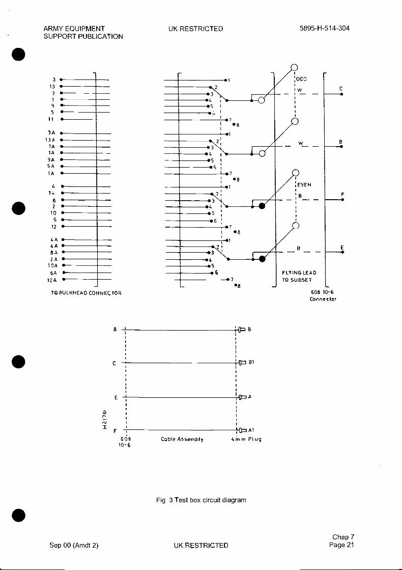
ARMY EQUIPMENTSUPPORT PUBLICATION
UK RESTRICTED 5895-H-5 14-304
I
e7I '8
•5 I
.6.7
BE
Fig 3 Test box circuit diagram
Sep 00 (Amdt 2) UK RESTRICTEDChap 7
Page 21
4001W
B—4
AEVEN
3 .—13 S7'1•9'5.Ii.—
13A S
74 5—14 U
94SA •14 U
4 5—14 5-8'25-
10 55.12 •4A 5—4A S8A 'ZA U
104 5S
12A •
7QBIRKHEAD CONNECTOR
B
C
E
IF
FLflNG LEADTO SUBSET
60B 10-6•8
IAI
. I
60810-6
4mm PlugCQbte

5895-H-51 4-304 UK RESTRICTED ARMY EQUIPMENTSUPPORT PUBLICATION
APU FIRE EXTINGUISHERS
19 The APU fire extinguishers are located in the central hatch between the APUs, and are accessedfrom the top of the vehicle. The fire extinguishers are operated by a pyrotechnic charge within theoperating head which is remotely fired when an electrical signal is received from the overheat detectorunit. When operated, the extinguisher discharges Halon 1211 (BCF) into the APU compartments.Halon is used because of its good extinguishant properties and low toxicity. Once the extinguisher hasbeen operated, the bottle and head must be replaced. The APU fire extinguishers and operating headsare unable to be serviced. The APU fire extinguisher bottle is constructed of very robust seamlesssteel, with the operating head permanently attached. A junction box is fitted to the operating head towhich the outlet pipe is connected.
Operation
20 For the operation of the APU fire extinguisher refer to Fig 4. When the initiator cartridge is fired thehigh-pressure gas created in the upper annular groove causes the frangible section of the charge plug torupture. The pressurised extinguishant forces the lower portion of the charge plug down the guide tube,past the non-return lugs, allowing the extinguishant to be directed through the outlet pipe to the APUcompartments. As the lower portion of the charge plug reaches the bottom of the guide tube it strikes theindicator pin, causing the indicator pin to protrude through the base of the junction box. The charge plugand the indicator pin are held in this position by the non-return lugs.
Chap 7Page 22
Fig 4 APU fire extinguisher operating head
UK RESTRICTED Sep 00 (Amdt 2)
.
.
.
.
OUTLET
UNFIRED - BEFORE OPERATION FIRED - AFTER OPERATION
ARMY EQUIPMENT UK RESTRICTED 5895-H-51 4-304SUPPORT PUBLICATION
APU FIRE EXTINGUISHER INSPECTION
21 The APU extinguisher initiator cartridge units have a limited life of two years service after removalfrom sealed packaging, or five years from the date of manufacture, which ever expires first. The dateof manufacture is stamped on the mounting flange.
22 The APU extinguishers are life-expired five years from the date of manufacture. The operatinghead and bottle must be overhauled by the manufacturer after this date. The date of the last overhaulis stamped on the operating head.
23 A regular inspection must be made to ensure that the extinguisher has not been discharged, bychecking that the discharge pin is not protruding from the bottom of the junction box.
24 The extinguisher should be removed annually from its bracket and inspected for chaffing,corrosion, leakage or other external damage. Before the extinguisher is removed from the bracket, theanti-recoil cap must be fitted to outlet.
25 The extinguisher is to be weighed complete with firing cartridge and anti-recoil cap. The weightmust be within 30 gm (1 oz) of that which is stamped on the operating head. The weight stamped on• the operating head does not include the weight of the firing cartridge or anti-recoil cap (which must befitted when weighing). To compensate for the weight of the firing cartridge and anti-recoil cap deduct88 gms from the reading.
26 Discharged, damaged or underweight extinguishers must be returned to stores using localarrangements.
27 The anti-recoil cap is to remain fitted until the extinguisher is secured in the mounting bracket.When satisfied that the extinguisher is serviceable, secure it into the mounting bracket. If a new orreplacement extinguisher is to be fitted, it must be weight tested before installation.
APU FIRE EXTINGUISHER INITIATOR CARTRIDGE FUNCTIONAL CHECKS
WARNINGS
(1) EXPLOSIVE HAZARD. INITIATOR CARTRIDGE FIRING UNITS MUST BE REMOVEDFROM THE FIRE EXTINGUISHER BEFORE MAKING ELECTRICAL CHECKS.
(2) PYROTECHNIC DEVICE. THE APU FIRE EXTINGUISHER INITIATOR CARTRIDGESCONTAIN GUNPOWDER. ALWAYS HANDLE WITH CARE.
(3) DANGER OF ACCIDENTAL FIRING OF THE APU FIRE EXTINGUISHER SYSTEM.WHEN TESTING THE APU FIRE EXTINGUISHER FUSE, USE ONLY A SAFETY OHMMETERTHAT OPERATES AT A CURRENT OF LESS THAN 13 mA.
28 To make electrical tests on the initiator cartridge firing units proceed as follows.
28.1 Securely mount the unit to be tested on a suitable fixture. The charge holder must beshielded but unrestricted in such a manner that an accidental firing will not harm the operator orother personnel.
28.2 Using a 250 or 500 volt insulation tester, check the insulation resistance between the twopins linked together and the body.
28.3 Connect a safety ohmmeter across both pins and measure the resistance. The readingmust between 5 and 6 ohms.
Chap 7Sep 00 (Amdt 2) UK RESTRICTED Page 23

5895-H-51 4-304 UK RESTRICTED ARMY EQUIPMENTSUPPORT PUBLICATION .
.
Fig 5 APU fire extinguisher
END
INITIATORCARTRIDGEFIRING UNIT
ANTI-RECOIL CAP
.
Chap 7Page 24 UK RESTRICTED Sep 00 (Amdt 2)
.
CORK GASKET7AUTOMATICHALON 1211EXTINGUISHERrYPE
bEUGRA TYPE
INITIATOR
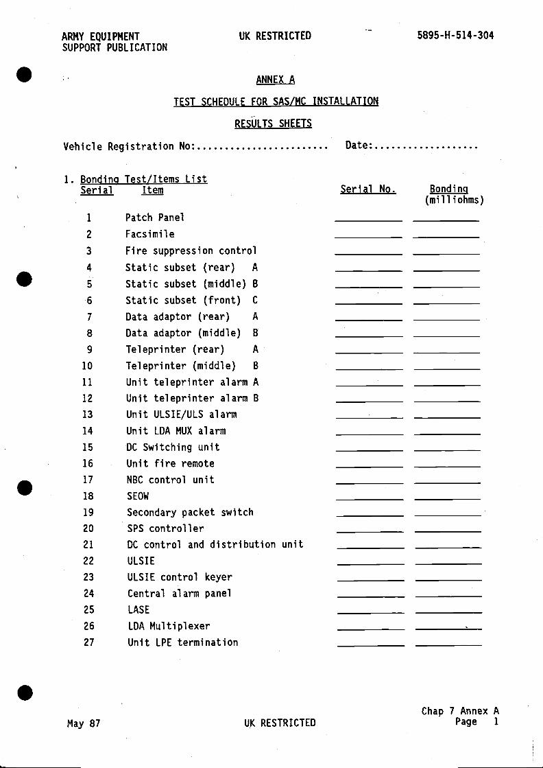
ARMY EQUIPMENT UK RESTRICTED 5895-H-514-304SUPPORT PUBLICATION
ANNEX A
TEST SCHEDULE FOR SAS/MC INSTALLATION
RESULTS SHEETS
Vehicle Registration No Date
1. Bonding Test/Items ListSerial Item Serial No. Bonding
(milliohms)
1 Patch Panel
2 Facsimile
3 Fire suppression control4 Static subset (rear) A
5 Static subset (middle) B6 Static subset (front) C
7 Data adaptor (rear) A
8 Data adaptor (middle) B
9 Teleprinter (rear) A
10 Teleprinter (middle) B
11 Unit teleprinter alarm A12 Unit teleprinter alarm B13 Unit ULSIE/ULS alarm
14 Unit LDA MUX alarm
15 DC Switching unit16 Unit fire remote17 NBC control unit18 SEOW
19 Secondary packet switch20 SPS controller21 DC control and distribution unit22 ULSIE
23 ULSIE control keyer24 Central alarm panel25 LASE
26 LDA Multiplexer27 Unit LPE termination
Chap 7 Annex AMay 87 UK RESTRICTED Page
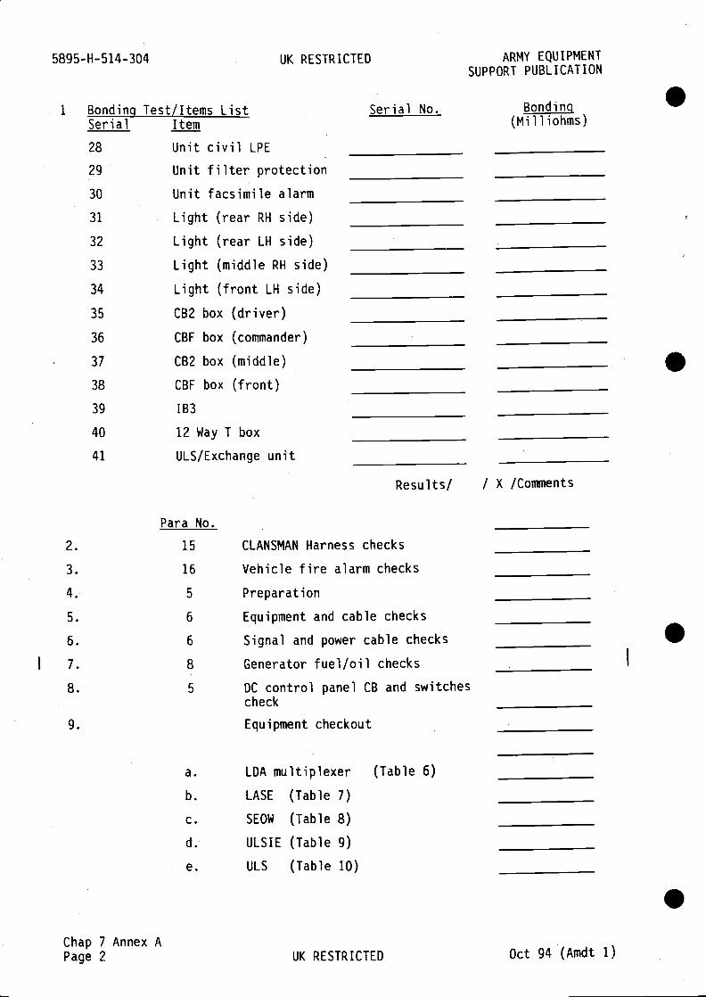
5895-H-514-304 UK RESTRICTED ARMY EQUIPMENTSUPPORT PUBLICATION
Bonding Test/Items List Serial No. Bonding SSerial Item (Milliohms)
28 Unit civil LPE29 Unit filter protection30 Unit facsimile alarm
31 Light (rear RH side)
32 Light (rear LH side)
33 Light (middle RH side)
34 Light (front LH side)
35 CB2 box (driver)
36 CBF box (commander)
37 CB2 box (middle)
38 CBF box (front)
39 1B3
40 12 Way T box
41 ULS/Exchange unit
Results! / X /Comments
Para No.
2. 15 CLANSMAN Harness checks
3. 16 Vehicle fire alarm checks
4. 5 Preparation
5. 6 Equipment and cable checks
6. 6 Signal and power cable checks S7. 8 Generator fuel/oil checks
8. 5 DC control panel CB and switchescheck
9. Equipment checkout
a. LDA multiplexer (Table 6)
b. LASE (Table 7)
c. SEOW (Table 8)
d. ULSIE (Table 9)
e. ULS (Table 10) .Chap 7 Annex APage 2 UK RESTRICTED Oct 94 (Amdt 1)
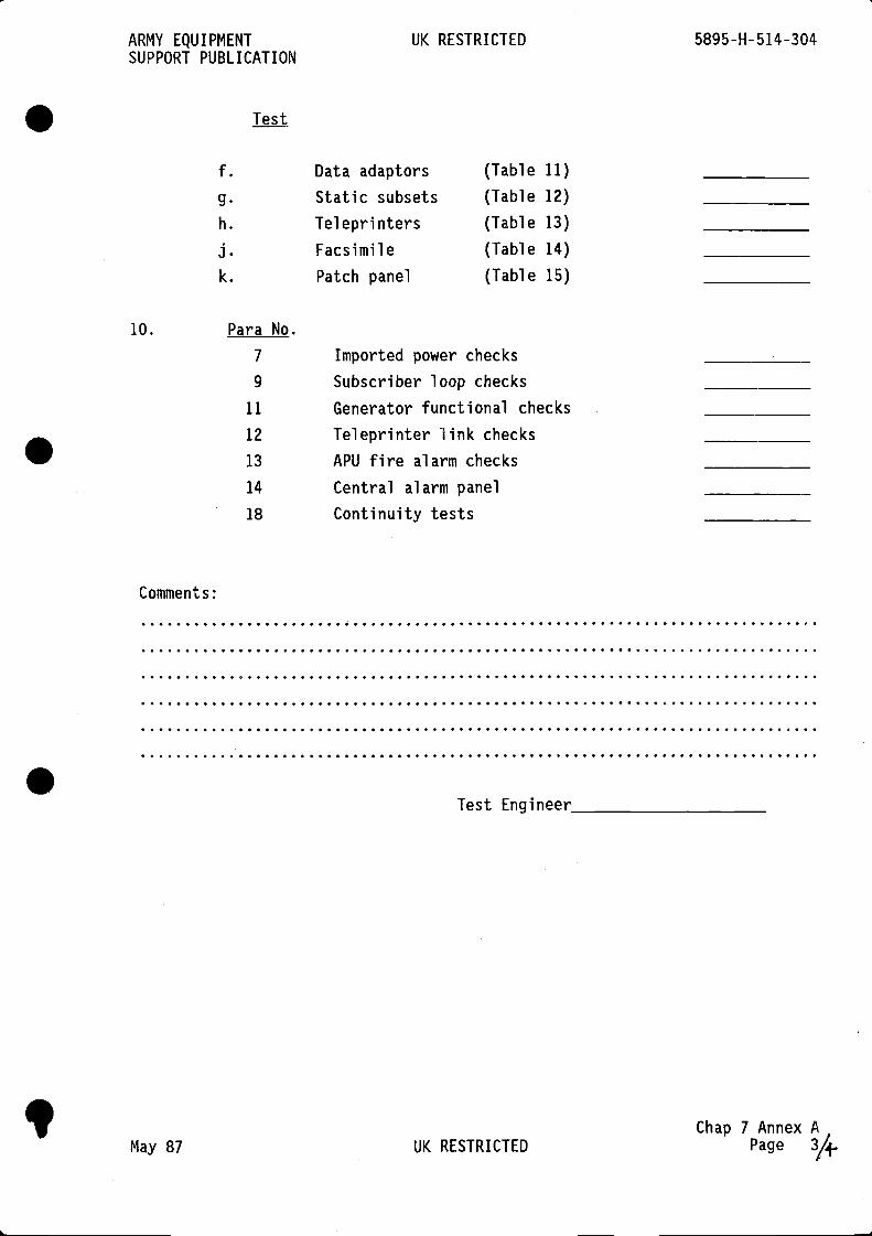
ARMY EQUIPMENT UK RESTRICTED 5895-H-514-304SUPPORT PUBLICATION
Test
f. Data adaptors (Table 11)
g. Static subsets (Table 12)
h. Teleprinters (Table 13)
j. Facsimile (Table 14)
k. Patch panel (Table 15)
10. Para No.
7 Imported power checks
9 Subscriber loop checks
11 Generator functional checks12 Teleprinter link checks13 APU fire alarm checks14 Central alarm panel18 Continuity tests
Comments:
Test Engineer
Chap 7 Annex AMay 87 UK RESTRICTED Page

.
.
.


UK RESTRICTED
.
.
.UK RESTRICTED