AND DEVELOPMENT COMMAND ABERDEEN G A … memorandum report arbrl-mr-03279 ... blast loading of...
72
RD-i38828 ARMAMENT RESEARCH AND DEVELOPMENT COMMAND ABERDEEN PROVI.. G A COULTER JUN 83 RRBRL-R-03279 UMCLRSSIFIED S BI-AD-F398 268'EM-E-8699 F/G 19/4 NL EhhhhhhhhhhhhE IEIII1IHIIII IIIIIIIIIIEE //////hBBhBBBI El
Transcript of AND DEVELOPMENT COMMAND ABERDEEN G A … memorandum report arbrl-mr-03279 ... blast loading of...

RD-i38828 ARMAMENT RESEARCH AND DEVELOPMENT COMMAND ABERDEENPROVI.. G A COULTER JUN 83 RRBRL-R-03279
UMCLRSSIFIED S BI-AD-F398 268'EM-E-8699 F/G 19/4 NL
EhhhhhhhhhhhhEIEIII1IHIIIIIIIIIIIIIIEE//////hBBhBBBI
El

0040
1IIllI 11 1.8.25
MICROCOPY RESOLUTION TEST CHART
0 0 0 0 • 0 0 0 0 0 0 0 0, 0 0 .

MEMORANDUM REPORT ARBRL-MR-03279
BLAST LOAD ING OF CLOSURES FOR USE
ON SHELTERS
George A. Coulter
4 ? 1 1 '12 3
U June 1983
* US ARMY ARMAMENT RESEARCH AND DEVELOPMENT COMMAND
BALLISTIC RESEARCH LABORATORYABERDEEN PROVING GROUND, MARYLAND
Approved for public release; distribution unlimited.
Q-

Destroy this report when it is no longer needed.Do not return it to the originator.
Additional copies of this report may be obtainedfrom the National Technical Information Service,U. S. Department of Commerce, Springfield, Virginia22161.
I
I
The findings in this report are not to be construed asan official Department of the Army position, unlessso designated by other authorized documents.
The j e of trade 'mies Jr 7zrufa ' noea -r 'his erortd r O C518titure semort Sj My cormnert'a~l prod7ct.
* UNCI ASSIFI ED3ECUR;Tl* CLASSIFICATION OF THIS PAGE (When Il)a( Enteed)
READ ISR('.REPORT DOCUMENTATION PAGE BEFORE C'MP E T.N ',. .'1<.
I. REPORT NUMBER $2 GOVT ACCESSION NO. 3. RECIPIENT, (_AT ALG, 3E P
MEMORkNDUM REPORT ARBRL-MR-03279 lY4. TITLE (and Subtitle) S. TYPE OF REPORi & F6 J (' t.EED
BLAST LOADING OF CLOSURES FOR USE ON SHELTERS Final
6 PERFORMING ORG. REP~ NL,,43ZR
7. AUTHOR(s) 8. CONTRACT OR GRANT N,.'M3ER/)
George A. Coulter
9. PERFORMING ORGANIZATION NAME AND ADDRESS 10. PROGRAM ELEMENT. PPR'JCT, TASK
USA Ballistic Research Laboratory AREA&WORIUNTNMB-RSATTN: DRDAR-BLT No. EMW-E-0699
* Aberdeen Proving Ground, MD 21005 Work Unit 1123C
II. CONTROLLING OFFICE NAME AND ADDRESS 12. REPORT DATE
US Army Armament Research & Development Command June 1983US Army Ballistic Research Laboratory (DRDAR-BLA-S) 13. NUMBEROF PAGES
70Aberdeen Proving Ground. MD 2100514. MONITORING AGENCY NAME & ADDRESS(if dffermni from Controlling Office) IS. SECURITY CLASS. (o! tf1i repor.)
* Federal Emergency Management Agency UNCLASSIFIED50o C Street, SWW1ashington, DC 20472 15, DECLASSIFICATIONDOWNGRAING. SCHEDULE
16. DISTRIBUTION STATEMENT (of this Report)
Approved for public release; distribution unlimited.
17. DISTRIBUTION STATEMENT (of the abstract entered In Block 20, it different from Report)
18 SUPPLEMENTARY NOTES
Fhis project was funded by Federal Emergency Management Agency, Yi() CStreet, SIV, Washinigton, DC, under project order no. EMW-E-0699, Project
* Officer Michael A. Pachuta.
19 KEY *OROS (Continue on reverse side It necessary and Identify by block number)
Blast Closures Steel DoorsBlast loading Ultimate Failure0,r, ors ihood P'anels
* Failure Loads
20. A BST-RACTr (oaftue -l ~rere *fob If neoom m Idevdlfv by block number) rsbResults are presented for the blast loading of wood beams,'pl1v, yo..!
clostires, steel gratinU'/plywood, and steel doors. Ultimate faiiltlr(. !,()Ithe closures and doors were determined for long duration hlist l'':i o t-l)
* the BRI. 2.44 m simulatir. Loading and deflection data are presented, "orthe test closures.
JA 7o 1413 EO? no. UF I NCV6SISOS&OLETE JNCLASSFIIFSECURITY CLASSIFICATION OF TNS AGF hW.sr 7 Fera r -

S.: MMARY
I. INTRODUCTION
The work reported here is a part of a research project, funded by theFederal Emergency Managment Agency (FEMA), Interagency Agreement No. E"W-1-0699, to upgrade existing shelters in both the key worker and host are is. lteobjective of this study is to determine closures suitable for shelter in theseareas. The ultimate failure of the closures was to be found from loadingtests in the BRL 2.44 m blast simulator. Data are given for solid wood beampanels with plywood skins, steel grating/plywood closures, and commercial
steel doors.
II. EXPFRIMENT
A solid core closure was constructed of wood beams (44-2 x 4's on edge)with 1.27 cm plywood skins nailed to the fbeams. A second type of closure wasconstructed from commercial steel grating covered on the upstream side withplywood to prevent air leakage. Commercial steel doors were tested as a third
* type of closure. All were supported loosely. Pressure-time loading auddisplacement histories were measured for each test as a function of the inputblast overpressure level. High-speed photography (1000 pps) recorded thebreakout of the closures. Average debris velocities were calculated forbreakouLt fragments.
III. RESULTS AND CONCLUSIONS
Loading-time and deflection-time plots for the closures tested are shownin the body of the report. The blast loads needed for each closure to reachultimate failure (blowout) were found to be about four times the calculatedallowable static load for the wood beam closure, about seven times thepublished safe load for the steel grating/plywood closure, and about one and,cne-half times the calculated allowable static load on steel doors assumingthey respond like a panel. All dead weight load from the closures' weight wasIgnored since they were tested in an upright, wall position.
o~For
0 PPIS AGE.- -.
F 'I VS I f

TABLE OF CONTENTS
LIST OF ILLUSTRATIONS..............................................
LIST OF TABLES......................................................
I. INTRODUCTION....................................................... 11
11. TEST PROCEDURE..................................................... 11
A. Test Fixture.................................................. 11B. Closures......................................................1IC. Instrumentation............................................... 12
UILI. R ESUL TS...........................................................1I
A. Data Tables................................................... 1B. Loading and Deflection Plots .................................. 2C. Failure %~des.................................................1
* ). High-Speed Photographs........................................ 41
IV.. ANALYSIS.......................................................... 44
A. Wood Beam/Plywood Closures .....................................14B. Steel Grating/Plywood Closures .................................u) C. Commercial Steel Doors........................................ 0D). Support Walls.................................................(-'1
V. SUMMARY AND CONCLUSIONS............................................602
ACK-OWEDGEMENTS......................................................... 62
REFERENCES......................................................... 64
DISTRTEL'TION LIST .................................................. 65
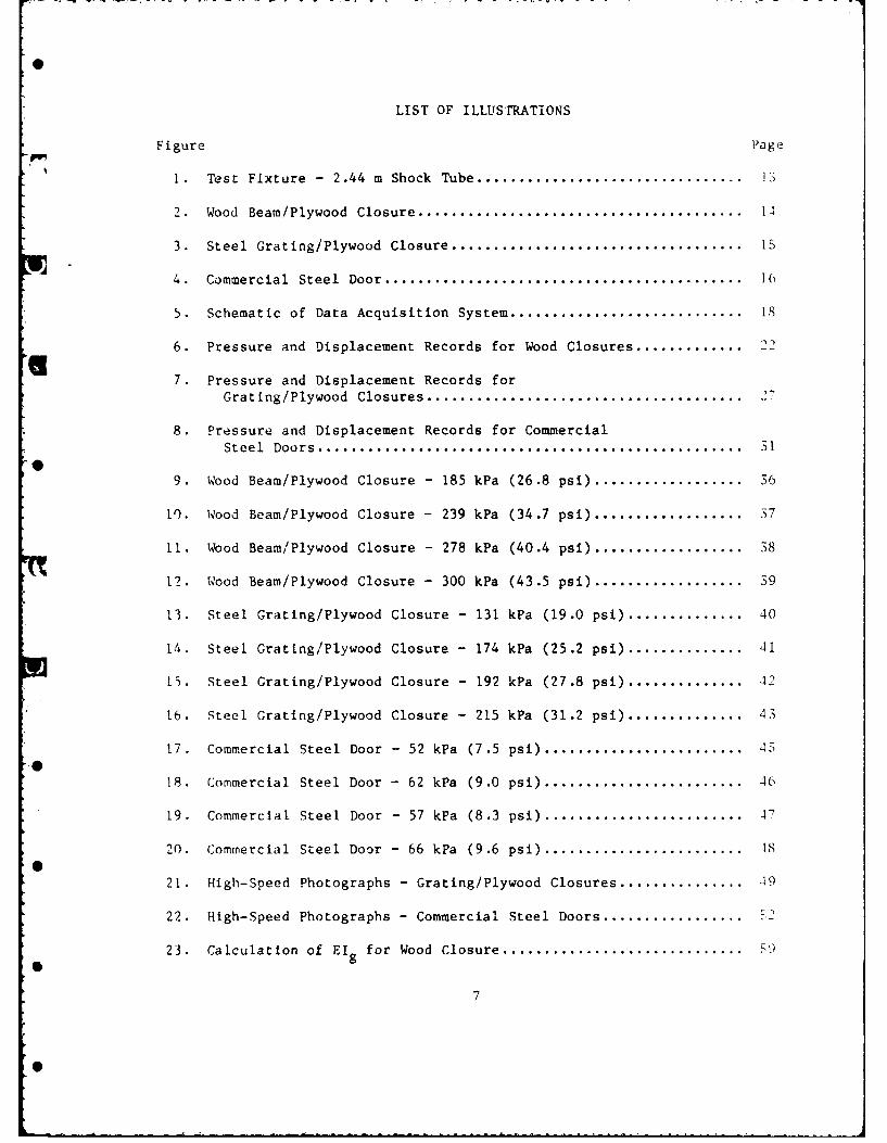
LIST OF ILLUSIRATIONS
Figure Page
1. Test Fixture - 2.44 m Shock Tube ................................ Q
2. Wood Beam/Plywood Closure ......................................... 14
3. Steel Grating/Plywood Closure ..................................... 15
4. Commercial Steel Door .............................................. K
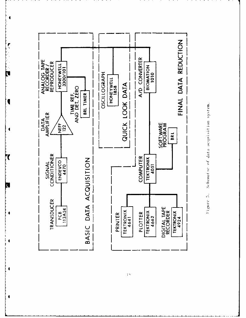
5. Schematic of Data Acquisition System .............................. is
6. Pressure and Displacement Records for Wood Closures ...............22
7. Pressure and Displacement Records forGrating/Plywood Closures ......................................... 7
8. Pressure and Displacement Records for CommercialSteel Doors..................................................... 31
9. Wood Beam/Plywood Closure - 185 kPa (26.8 psi) .................... 36
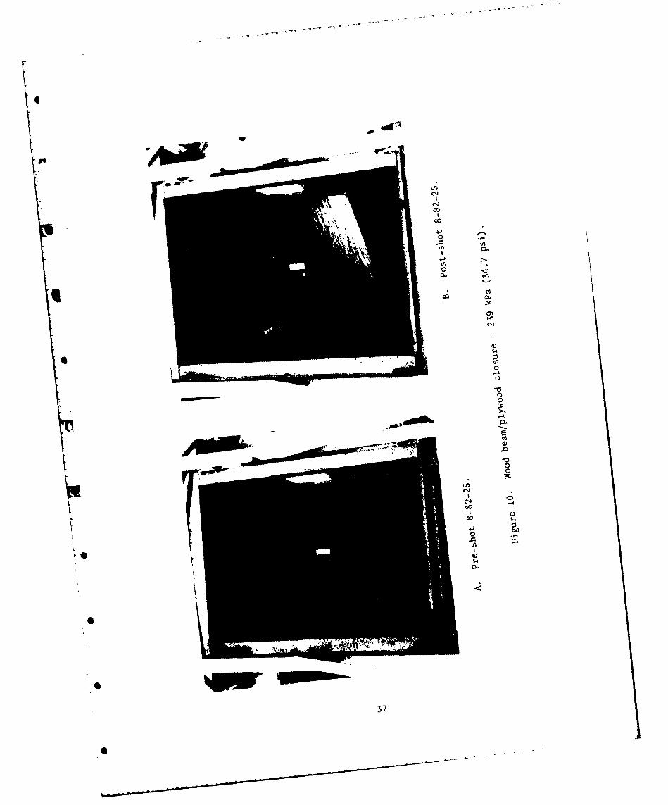
10. Wood Beam/Plywood Closure - 239 kPa (34.7 psi) ..................... 7
11. Wood Beam/Plywood Closure - 278 kPa (40.4 psi) .................... 38
12. Wood Beam/Plywood Closure - 300 kPa (43.5 psi) .................... 39
13. Steel Grating/Plywood Closure - 131 kPa (19.0 psi) ................ 40
14. Steel Grating/'Plywood Closure - 174 kPa (25.2 psi) ................ 41
15. Steel Grating/Plywood Closure - 192 kPa (27.8 psi) ................ 42
16. Steel Grating/Plywood Closure - 215 kPa (31.2 psi) ................43
17. Commercial Steel Door - 52 kPa (7.5 psi) ..........................45
180omrilSelDo 2ka(90pi ............ 4
19. Commercial Steel Door - 62 kPa (9.0 psi) .......................... 47
19. Commercial Steel Door - 57 kPa (8.3 psi) ...........................U
21. High-Speed Photographs - Grating/Plywood Closures .................49
22. High-Speed Photographs - Commercial Steel Doors .......... 5
23. Calculation of El for Wood Closure ................................
7

LIST OF TABLES
Table Padge
1. Ambient Test Conditions ...........................................
2. Loading Data for Closures .........................................
Ma terial Properties of the Closures................
4. Summary of Loading Results for the Test Closures ..................
9

1. INTRODUCTION
The results reported here are from a study conducted at the Bailistic
Research Laboratory (BRL) and funded by the Federal Emergency Management
Agency (FEMA), Interagency Agreement No. EMW-E-0699. The purpose of thepresent work is to test a variety of expedient closures suitable for use on
both host and risk area shelters. The closures are to be used to sealopenings from small pipe vent size to entrance-type such as would be needtidfor underground shelters.
WPrevios work at the BRL1-3 sponsored by FEMA has verified designprocedures indicating that plywood and plywood stressed-skin panels are
satisfactory expedient closures for low presure (13.8 kPa, 2 psi) hostareas. They are also effective closures for small, vent-type openings, in therisk area (345 kPa, 50 psi) with suitable supporting fixtures. The need,therefore, is to design and test closures for the higher pressure risk area
: Afor entryway-size openings.
Accordingly, three types of closures were prepared for testing at the BRL2.44 m (8 ft) Shock Tube Facility: wood beams with plywood skins, steelgrating with a plywood cover, and a commercial steel door selected from thelast set of tests (Reference 3). The test procedure is described in the nextsection.
II. TEST PROCEDURE
Details of the closures and recording instrumentation are brieflydescribed in this section.
* A. Test Fixture
The test fixture consisted of a flange assembly b~1ted to the downstream
end of the test section of the BRL 2.44 m shock tube. A rectangular opening,
F1 George A. Coulter, "Debris Hazard from Blast Loaded Plywood Sheet
Closures," Memorandum Report ARBRL-MR-02917, Ballistic Research Laboratory,March 1979 (AD A071460).George A. Coulter, "Blast Loading of Construction Materials and ClosureDesigns," Memorandum Report ARBRL-MR-02947, Ballistic Research Laboratory,
August 1979 (AD A077116).George A. Coulter, "Blast Loading of Wall Panels and Commercial Closures,"Memorandum Report ARBRL-MR-03154, Ballistic Research Laboratory, February
4 1982 (AD B063574L).I.L. Murphy, "Upgrading Basements for Combined Nuclear Effects:Predesigned Expedient Options II," SRI Project 6876 Technical Report, July
1980.Brian P. Bertrand, "BRL Dual Shock Tube Facility," Ballistic Research
Laboratory Memorandum Report 2001, August 1969 (AD 693264).
11

1.219 x 1.676 m (4 x 5.5 ft), in the end flange allowed the closures to beloaded by reflected pressure from the wave produced in the shock tube.Ultimate failure was defined as a broken out closure or a closure pushedthrough the flange opening. The grating and door closures were mountedloosely on all four sides. The wood beam was mounted loosely at each sideonly. Figure 1 shows the test fixture used.
B. Closures
Sketches of the closures are shown in Figures 2-4. All tests wereconducted with the closures mounted in the vertical position. Wooden frameswere used to mask each of the closures to give a smooth wall effect for thetest. The clearance of about 0.5 cm that separated the closure from the framewas covered with strips of rubber, with a loose edge left on the closure side.
The beam closure shown in Figure 2 was made of 2.81 x 8.89 cm (2 x 4's)joists on edge, sandwiched and nailed, between sheets of 1.27 cm thickplywood. The short ends were supported with a length of 7.62 cm during thetests of this closure. As noted on the sketch, the face grain of the plywoodsheets ran in the direction of the 2 x 4's to give the greatest strength.
Figure 3 shows a sketch of ordinary steel grating, covered on one sidewith plywood (0.635 or 1.27 cm) to con-.ain the blast pressure. The gratingnormally is sold in a standard width if 0.91 m, so two widths were attached to
K cover the end flange opening of 1.219 x 1.676 m. Grating was supported 7.12cm on all sides.
The third closure tested is shown in the sketch, Figure 4. It is thestrongest of a set of commercial doors tested before (Reference 3) for FEMA.
The doors were full-flush steel, no cutouts, and had internal bracing with a
filler of rock wool for Insulation. See Figure 4 for supported areas on each
All closures were tested to ultimate failure where major portions (or allof the closure) were blown from the end flange.
C. Instrumentation
The blast pressure load applied to the closure was measured at a point onthe wooden masking frame 11.43 cm from the long edge of the flange opening.The transducer was approximately centered vertically along the height of theframe. The output from the transducer (PCB Model 113A24) was suitably ampli-fied and recorded by an FM CEC 3300 tape recorder. Records were available
4 for a quick-look from an on-site oiscillograph to determine necessary record-ing changes for the next test.
The displacement of the closure wa 9 tracked with an OPTRON Mbdel 501Electro Optical Displacement Fjllower. A light cardboard target, painted
6 Model 501 Optical Displacement Follower," OPTRON, Division of UniversityTechniques Inc., 30 Hazel Terrace, Woodbridge, CT 06525.

4
p.
IC.,
U 4~J
I -~-~ C-.,
I 0
I0
Cl
4-.,Cl)C)
HI
I
I
13I

(-I
0. to u
~,e.
9/
0 1,1
I0
0C
73
0
zC
U
CL C)
UJLL Ecoo L~uISYS L
o( .: . < LrZ~c~.I v, q~jZcwi
x~ ~ ~ Iu&CZ

Id
cnU
E
CWC
cwcI ~ ~ C 1..c. <_
~ 0 ~ CA-
o-
zL
CV
EIu I

K'ULU
Kz-\ w
z
00
ujI LJ .
IN, ., 0,Cj C zn0z~0 N
Nj ON
"I'4
94 0CL 6NV)H
N 0 'flU-
ad C1 L- L< z
U 6)
U, .U ''00 z z 0U
LU -Z ru 0~ Z
z- -CD z
Ln -bu- -- 1 00 cn -!02 a

0i
black, was at tached with an 1. U..i 1 P t r Ite Ie,- r, Theblack target was trackeA agaI nt i white backr .nd by t:follower during tht tes!ts. The ! .tOCIIl t rie i n3 t m , . , , 'erttLd
-, to an electron image in which the e.. tro , i-nsit,, wa pro;.ort -i t , thecorresponding lIght from the targLr. "'he e1ectrical oVt';t I.,, wa srecorded by the tape macine. 'Ie data icdu, tiou p:, '.sI MC AS or
the pressure data. See Fgure 5.
The instrumentation on tie closure wn suppl c ,nt. U ", I h Lg.-speed camera(Red Lakes HYCAM) opera t ing at 1000 pictures pet second (ppzs. lie camera was
used to record any breakout of a foiled closure. it was a scF used tosupplement the displacement follower whcoe tht- follower -%-r ranged.
11!. RESULTS
The results are presented in three parts: data tables, loading anddeflection records, and high-speed photographs.
A. Data Tables
The shot number, closure type, ambient pressure, and ambient temperatureare listed in Table 1. The shot results such as loading pressure, transient
deflection, permanent deflection, vibration frequency, and damage to theclosures are listed in Table 2.
The wood beam/plywood closures (Shots 8-82-23 to 8-82-27) were testedthrough 4 range of loading pressures from 173 kPa (25.1 psi) to 300 kPa (43.5
psi). Slight damage to the downstream plywood skin by budging occurred at thelow end of loading range. At 300 kPa (43.5 psi), the closure was in place andeffectLve although the downstream plywood skin was broken. Two frequencies of,ibratlon were measured for the wood closure: an initial higher one of 102-121 HZ and a lower secondary one of 16-20 Hz. Under higher loads approaching,ilmate failure (breakout), these vibrations tend to damp out.
'he loading range for the steel grating (Shots 8-82-28 to 8-82-31) variedfrom 131 kPa (19.0 psi) to 215 kPa (31.2 psi). The blast from Shot 8-82-28
.* caused the two parts of the grating (and 0.635 cm plywood sheets) to separateat the center line. No fasteners were used on this shot to hold the twogratings together. The flat rubber seal was blown through between the twogratings to allow the blast wave to blow through. Four 1.27 cm diameter U-bolts were then used on Shot 8-82-29 to fasten the two pieces of gratingtogether. The grating remained together at a blast load of 174 kPa (25.2 psi)
* but some of the cross bars near the center were pulled partially loose from
the bearing bars. The loading was increased to 215 kPi (31.2 psi) which blewthe closure completely out of the shock tube. Th2 pressure was decreased andthe inside cover sheet was changed to 1.27 cm thick. 11he grain of the face
plies of the plywood cover sheet was changed to a vertical (across the bearingbars) direction so the seam would not be in the middle. This grating/plywood
* closure operated successfully at 192 kPa (27.8 psi).
17
. . .. . . . . . . . . _ . . .. . . . . . . . . .
IL
'L z
LLJIJL 0W.i-j 0l z
CZ I0 >.rI
jU I;
U'-
IU N~IU
I LU Z. LU T - , I
Z;z > N - 0'uI z 0 -. i
4O I* uI I 'Luu i L1 V)UI L -
z L0,

TABLE 1. AMBIENT TEST CONDITIONS
6 Ambient Ambient
Shot Type Closure Pressure Temperature DatekPa "C
8-82-23 Wood Beam/ 101.9 31.7 May 11, 1982
Plywood (PSSP)
8-82-24 44-2 x 4's on 102.0 27.8 May 13, 19828-82-25 edge w/two 102.2 25.6 May 18, 19828-82-26 1.27 cm skins. 101.5 28.3 May 20, 19828-82-27 Supported on 102.0 19.4 May 24, 1982
long edges.
8-82-28 Grating w/0.62 cm 101.6 39.4 May 26, 1982plywood skin.
8-82-29 101.6 18.3 May 28, 19828-82-32 Grating w/1.27 cm 101.3 25.6 June 2, 1982
plywood skin.
8-82-31 Supported on 103.1 29.4 June 3, 1982all edges.
8-82-32 Commercial 101.6 26.1 June 8, 1982
8-82-33 steel doors, no 101.8 21.7 June 10,1982
8-82-34 cutouts in doors. 101.8 18.9 June 14, 19828-82-35 Supported or, 101.8 27.8 June 15, 19828-82-36 all edges. 101.2 27.2 June 16, 1982
r
I
19
6

OL0 . 0(v .0 0
Aj~~~ ~ ~ Q) 1 .0W 1 6 V -4 V '
0o W 0 0O 0 4 §m.
4- M)M~ M~f r
sw ~ ~ c ) tor
"0 o0 w w 0 (30 tk- 1-0 000 . 6J A .J C: .2 -j
r 3 co 1- m 0 0-4-0
OC. IC-q~ 41i s I w 8 z L z
A4 A.c 0 g
r I I I I ~,4,-
>uz.
I-
m Il IT -
z
4. a, -- I IT U') u I I I ID Ifl .l *I (w 111 C
Q) A A A
cc -. -. l I C.) 00' 1 1 1 I lrr W)-.rs
AA A
*c wI 0. C' m T 1 -4 m J
0~0
0- 0
0 00 0 C'J -4 Q) m CL> 4) 0
C.r) 3 li Q) 0 V w 3u -a~
1111 lii gu 1 cici ci i
II I I I 1 1 I I I I
20

Thie third type of closure - the steel corncurcial door -was weak ever'. wlhensupported on all four sides. The door was completely blown out on Shot8-82-32 at a loading pressure of 66 kPa (9.6 psi). The door behaved somewhatinconsistently on Shots 8-82-34 and 8-82-36. The last shot may have beensomewhat larger (at least, during the initial rise) but the door served wellas a closure on this shot. During Shot 8-82-34, however, the door was bentbadly and did not close the flange area against the blast wave during theshot. A possible explanation is that the face sheets were not spot weldedequally well in the two cases. All cases considered, the commercial doorsfailed at loads lower than either the wood panels or the grating/plywoodclosures.
B. Loading and Deflection Plots
Figures 6-8 show the pressure and deflection as a function of time duringthe loading period of the blast wave. The upper pressure record was, of course,modified if the closure opened and allowed blas' leakage past the closure.The bottom record (when available) represents the motion of the center of theclosure under load as a function of time. When the closure acted correctly,the deflection record follows well the loading pressure. See Shot 8-82-25,33, and 35 as examples of correct sealing - no venting. The pressur; -tine
* record modification by closure failure is illustrated by Shots 8-82-26, 30,and 32. The rarefaction from the release of the pressure load decreases thepressure at the transducer location to a minimum pressure at about 150 msmeasured from blast wave arrival at the closure. Shot 8-82-34 shows ararefaction beginning a little beyond 300 ms indicating closure failure latein the loading cycle. The failure mode is described in Section C below, andclosktre breakout is best seen on the high-speed photographs of Section D.
C. Failure Iides
Figures 9-20 show photographs of the three types of closures tested withthe various types of failure. Figures 9-12 show the wood beam/plywoodclosures. At 185 kPa (26.8 psi), Figure 9, a slight bulging occurred duringthe blast loading. Failure of the plywood occurred at levels of 239-278 kPa(34.7-40.4 psi), Figures 10 and 11, by tearing and breaking loose. Breakoutoccurred at 300 kPa (43.5 psi), Figure 12, with complete failure of the bottomhalf of the closure. (The remaining top half fell to the bottom.) 2 x 4'swere splintered and the plywood skins were shredded.
The failure process for the steel grating/plywood closure can be seen inFigures 13-16. The grating was furnished by the supplier in a size such thattwo sections were needed to cover the flange opening. No center fastenerswere used on Shot 8-82-28, Figure 13. Separation and blast leakage occurredat the center with the 131 kPa (19.0 psi) loading. For the following shots,U-bolts or bolted plates were used to fasten the grating at the center line.This worked well with the 174 kPa (25.2 psi) and 192 kPa (27.8 psi), Figures14 and 15, (Shots 8-82-29 and 8-82-31). The plywood front sheet (1.27 cm) wasalso changed so the face grain was vertical. A better seal resulted at thefastenings with this plywood orientation although the center deflection of thegrating was about 19 cm (7.5 in.). The 0.62 cm plywood was.I uISed 011Y Oil Shots
0 8-82-28 and 8-82-29.21 Tx ~t~w h7TU

TEST:FEMA PANEL TEST250 SHOT:8-82-23
TYPE:PSSP-2X4
288
8 IS 30 5I0 5
* TIME, MSEC
TEST:FEM4i PANEL TEST3 SHOT:8-82-23
TYPE: PSSP-2X4
2
--
1L5 3045 0075
TIE8ME
Fi0ir . Pesr addslcmn eorsfrwo lsrs

TEST EMA PANEL TEST250258 SHOT:8-82-24
TYPE. PSSP-2X4
200
00
0 ISO 300 450 0 758
TEST:FEMA PANEL TEST6 SHOT:8-82-24
TYPE: PSSP-2X4
L) 4
Lj 2= 3LJ
4=1
0 ISO 388 458 600 750
TIME, MSEC
.nrt(~ rr.-ztire aild ti i Mp I; cc n~ft records tFor wood c Ilosures- (Colot 'd
I2
L

TEST:FEMA PANEL TEST
SHOT :8-82-25388 TYPE: PSSP-2X4
258
a IS 30 45 68 5
TIME, MSEC
TEST:FEMA PANEL TEST4 SHOT :8-82-25
TYPE: PSSP-2X4
3
22
I-

pTEST:FEMA PANEL TESTSHOT:8-82-26
488 TYPE: PSSP-2X4
350
388
258L 288
Ci- ISO158
I tso
8 I I i1 I
8 158 388 458 600 750
TIME, MSEC
TEST.FEMA PANEL TEST38 SHOT:8-82-26
TYPE:PSSP-2X4
20
z I5
LjJ
C,.)
_~ I I I I
*158 388 458 680 758
TIME, MSEC
* i r, (, . Prustlre, and di splceoment records for ,OAJl v'ii.:'c- nl'd.
• .... ...

TEST EMA PANEL TEST
TYPE: PSSP-2X4
300
S 200
* 108
80 3w ~ 458 600 758
TIME, MSEC
TEST:FENA PANEL TEST8 SHOT* 8-82-27
TYPE:PSSP-2X4
6
2
-2-
I SO 300 458 688 758
TIME, MSEC
I I tjcue . Pressure- and displacement records f 'r w~ood c lostires (cont d.
.2

TEST:FEMA PANEL TEST288 SHOT:8-82-28
TYPE:GRATES
ISO
88 15080 4508 750
TIME, MSEC
TEST:FEMA PANEL TEST18 SHOT .8-82-28
TYPE:GRATES
8
6
4
-2
ISO5 380 458 00758
TIME, MSEC
yr i wur'lfld di I kicc;ieflt records for '-rat il."4 p ~ood c I o s t re u

TEST:FEHA PANEL TEST388r SHOT: 8-82-29
TYPE: GRATES
258
288
Is
0Ise 0 458 0 758
TIME, MSEC
NO DISPLACEMENT RECORD
Fi- -7 Pressuire and di sl~acment records for grat inQ/plyw~ood closures (cont d).
28

TEST: FEMA PANEL TEST
258 SHOT: 8-82-38TYPE: GRATES
208
ISO
"' 100
58
08 IS 380 458 688 750
TIME, MSEC
NO DISPLACEMENT RECORD
S
F J',-li' 'cs sui'e aind disIplaclcmt records for tin'/plY\ood closures (cont' (.
2S

TEST FENA PANEL TEST250 SO:-23
28
158
100
58
00
TIME, MSEC
NO DISPLACEMENT RECORD
Iirc 7. f'r'(ssuro aind displacement recordls f'or grat ingpl \wood c losiircs (cant d.

0
TEST: FEJIA PANEL TEST
*r 80 SHOT 8-82-32TYPE:STEEL DOORS
0b
Uj
8 158 380 450 68 750
0 TIME, MSEC
NO DISPLACEMENT RECORD
0e 4
i i< I F,. I'sr(' L ;II1( d i s1~l ;icemn ,nt r',:'or~is tFr L'iT~illc[". i!* st-,c 1 jr~()s.
31
....

TEST:EMA PANEL TEST60 SHOT:8-82-3368 TYPE;STEEL DOORS
45
30
0.
8 ISO 388 450 688 750
TIME, MSEC
TEST:FEMA PANEL TESTS
6 SHOT:8-82-33TYPE:STEEL DOORS
L) 4
u-
LU 3
cn 2
8 I58 308 458 688 758
TIME, MSEC
1 igtie 1 'nsiirc and di sp I icoment l'eeor'dS for commer ilii**.:t c, I doors cont '(1
0J

TEST:FENA PANEL TESTSP 8 SH1OT:8-82-34
TYPE:STEEL DOORS
68
40
20
48
62
0 ISO 388 458 680 758
TIME, MSEC
TE'OILS t:FE" PANE11WL TESTSSHOT .8-82-3

r TEST:FEMA PANEL TESTS
88 SHOT: 8-82-35TYPE:STEEL DOORS
68
48
28
8 Ise 300 458 680 758
TIME, MSEC
TEST:FEMA PANEL TESTS10 - SHOT:8-82-35
TYPE:STEEL DOORS
8
6
-cc
-a 4
2
0 8I5O 380 450 600 758
TIME ,MSEC
Iic~~re M. C ye S u 'e md d is'plIac ement rec ord s for Comimerc i alSteel doors (cont 'ci

TEST:FEMA PANEL TESTS
880 SHOT:8-82-36TYPE:STEEL DOORS
68
cx 48
* 20
~~0
TIME, MSEC
TEST:FEMA PANEL TESTS
18 SHOT:8-82-36TYPE:STEEL DOORS
6 6
2 IS8 300 458 600 758
lItlE, tISEC
I ~ii' ~ Pressure and di splacement rccords. for commrciail* steel doors (cont'd).
35

00
0
0-
UG
Ire)
,;Am0
Go4
-. 36
00
0 -4
ccn
00
-4
0n
0?00
373
................

00
oo-t
0
- 4
1-C.
4-)a0a
4V)
* 38
all
0
.-
390

-, 00
0
4-
0
go
I 0
Now"
* 00
0?
00
0
4C
4.)1
00
4-j
loo
"Milo
...........

00
~~V)
00
tz

00
4-)
U0
ccq
0
1:1.
brC
C) cn
- t

7
The commercial steel doors began failure by separation oi the spot welded
hdownstream face sheet (Figures 17 and 18). Figure 19 illustrates the twisting
of the door that occurred at a load of 57 kPa (8.3 psi). At a load of 66 kPa(9.6 psi) the door was thrown out of the holder 40 in from the ,id of the shock
tube. See Figure 20. "ihe failure began at the face sheet seam but finalbending occurred at about the center of the door.
D. High-Speed Photographs
The high-speed camera was set up on the south slid of the shock tube. The
field of view started at the beginning of the end flange and covered adistance of about 2.7 m beyond the flange.
Films were obtained for Shots 8-82-30 and 8-82-32 (steel grating and door
closures) at a framing rate of 1000 pictures per second (PPS). No film wasobtained for the wood beam/plywood closure failure because of camera
malfunction. Both films show the debris hazard created by failure of the twotypes of closures. Time starts just before debris exits the end flange.
* Figure 21 illustrates the kind of debris pattern created from theshredding of the plywood cover sheet. At about 40 ms after plywood sheet
failure the grating was blown out at an average velocity of about 35 m/s.
Figure 22 shows the failure of the steel door. After bending and losing
contact with the closure fixture, the door is expelled at an average velocityof 25 m/s. Velocities as measured from both the steel grating/plywood and the
steel door after failure are judged to create a vary dangerous debris hazard.
IV. ANALYSIS
The analysis will follow that of the design procedures specified inReference 4 for plywood skin stressed panels (PSSP). See Table 3 for materialproperties. This method will be used for Predicting the ultimate failure ofthe wood beam/plywood closures and of the steel doors. The table7 value of
allowable loads will be used for the steel grating/plywood closure.
A. Wood Beam/Plywood Closures
Closures of this type (PSSP) tend to have4 the weakest failure mode inhorizontal shear. Accordingly, the allowable total load - horizontal shear - is:
(2 (',Fvt) / (U' Qv)) (Elg/Estringer), (i)
7 "Macarco Safe Load Data-Fed Specs RRG-661a," Mc~aster-Carr Supply Co., 640West Lake Street, Chicago, IL.
I..

cCd
cCd
*~ N~
00
4 05

2
00
-4
V)0
U.
4--
0
a)
46

'4d
Lfn
00
47J

flyl
r4
0?
4 00
CA
IH
4
r44
00 -
ON-

Shot 8-82-30
0 ms 30 ms
* 10 ms 40 ms
20 ms 50 ms
1 iure 21. High-speed photographs grating/plywood closures.
6 49

Shot 8-82-30
60 ms 90 ms
1AA0A
70 ms 100 mns
80 ms 110 ni
r2 1 Hfigh - speed pliot og ri g rh i i np g1j Iviwoocx I 1 17-C S (coil t d
5

Shot 8-82-30
~lb
120 ms 150 ms
6 IL
130 ms 160 ms
6j
140 ms 1( n
I'iiglre 21. High-speed photographs -gr.t npp -wood c tr~
51

Shot 8-82-32
0 ms 30 ms
10 ms 40 ms
20 ms SO ms
1 ,Iru 22. High-speed photographs - cornnerci al steel doors.
S 32

Shot 8-82-32
60 ms 90 ms
70 ms 100 ms
80 ms 110 ms
F igure 22. High-speed photographs - commercial steel doors (cont'd).
53

Shot 8-821-32
120 ms 150 mns
130 mns 160 mns
1-10 mns 170 1
icI- High- speed photographs -commere i a I stee I doors; f cont 'd'
Shot 8-82-32
180 mns 210 mns
190 ms 220 ms
2100 m's 230 mns
SS

Shot 8-82-32
240 ms 260 ms
250 ms 270 ms
Figure 22. High-speed photographs - commercial steel doors (cont'd).
6 6

CDc Ln -4
x
Cn C 71
C) C)
00 00 -
CD
c Clcl x x x
CC
.~ 0 Lf)
o )
C- t) \0
*n I
r- 4n
00
CD u
- -t4N
-f) I
U -4 X
Cc 00 U
.7S7
IL 7

.:iere Pv = allowable load - horizontal shear (kPa),
(F v - allowable stress in stringer horizontal shear (655 kPa),
t - sum of stringer width (167.6 cm),
Elg M stiffness factor from Figure 23 (17.46 x 101 0 kPa-cm 4),
Eskin m modulus of elasticity for plywood skins including percentage
(10%) increase (13.64 x 10⁶ kPa),
Estringer m modulus of elasticity for stringer including percentage
(3%) increase (12.77 x 10⁶ kPa),Z and Z' (121.9 and 167.9 cm), and the
statical moment,
Qv m Qstringer + Qskin (Eskin/Estringer)' (2)
The terms of Qv are:
Qstrinfer = cross section of all stringers either mbove or below N.A.times ts centroidal distance from N.A. (1653.9 cm),
Qskin = All for chosen skin times moment arm (350.9 cm3), and
E's are as before (with percentage increases) (kPa). 10% addedfor Eskin and 3 % for Estringer. Q = 2028.7 cm3.
Values for plywood and stringers (2 x 4's) used in Figure 23 and Equations 1and 2 are taken from References 8 and 9 after changing to metric units. The
value calculated for Pv is 72.42 kPa (10.5 psi) as the allowable load.
The dynamic load required to cause ultimate failure is:
Pdm = 4 Pv (1 -i ), (3)
where the ductility ratio, 1, is taken as 2, and,
Pdm = 3Pv" (4)
The predicted load to cause ultimate failure of the closure is 217.3 kPa
(31.5 psi).
8 "Design Values for Wood Construction - A Supplement to the 1977 Edition of
National Design Specification for Wood Construction," National ForestProducts Assoc., 1619 Mass. Avenue, N.W., Washington, DC 20036, April
1980.9 "Plywood Design Specification," American Plywood Association, P.O. Box
2277, Tacoma, Washington 98401, December 1978.
58

00
-0 0 0q .* Ojx x
tI 10 -0 '40
ti4 - 4 C,4
Go co 0
L co 0 0D
C-4 4 OD0
NON
U Go
U '-
u.00
0 EN %00U u CO
N-o 0.
Lu x - r,;
Z~: '- E*
z I-a - cv
0 0, 4 0
z C"
t,.) W '
Z Z~ CN0I-
UU i
Uzi,
0
The frequency for the first mode of panel deflection is given by Equation5 (Reference 10). The panel is assumed to act like a beam that is uniformlyloaded and loosely supported at the ends.
f = 1.56 ' (5)
where f - frequency of first mode (Hz),
= clear span of the closure (1.219 m),
E1 =EIg - flexural rigidity of panel (17.46 x 10⁵ Pa - m 4 ), and
U w - weight/unit length of clear span (92.08 kg/m).
The frequency for the first mode is 144.6 Hz.
B. Steel Grating/Plywood Closures
-. The safe load for the steel test grating (neglecting plywood) given inReference 7 is 27.8 kPa (4.03 psi). The dynamic load is again calculated fromEquation 3 above with V - 10 for steel (Reference 4). Pdm equals 105.6 kPa(15.31 psi). No frequency of vibration was calculated for the steel gratingclosure.
C. Commercial Steel Doors
The steel doors tested were a flush-type with steel face plates. Someinternal stiffeners were used in the construction of the doors. See Figure 4in Test Procedure for view of cross section.
The manufacturer of the doors did not Itst any allowable load other thanthey had to meet wind load specifications. Calculations were made for thedoor assuming that it would act like a stressed skinned panel. The allowablestatic load for panel deflection was found from Equation 6 when looselysupported at the long ends:
25 2 O.1S.Pd = 1/[C U' (-84 (EIg)+ 0AG + DL (6)
10 Theodore Baumeister, Editor, Mechanical Engineers' Handbook, McGraw-Hill
Book Co., Inc., New York, NY, 1958.'John Hancock Callender, Editor-in-Chief, Time Saver Standards; A Handbookof Architectural Design, Fourth Editici, McGraw-Hill Book Co., Inc., NewYork, NY, 1966.
60
6

where Pd = allowable total loid-panel deflection (kPa),
C = factor - 360 for floors,
Elg stiffness factor - (5.07 x 101 0 kPa-cm4),
A = actual total cross section of braces (15.58 cm 2 ),
G = modulus of rigidity nf stringers (79.57 x 10⁶ kPa),
= clear span of panel in direction of stringers (167.64 cm), and
= clear width of panel (109.4 cm).
The dead weight (DL) was set to zero since the doors were all tested asupright wall panels. Pd = 21.0 kPa (3.04 psi). For steel sheets supported onall four sides, instead of two sides, Reference 4 recommends a load factor of
*2.139 (times the load calculated for end supports only) for a span ratio(longer to shorter) of 1.52. The calculated allowable load for support on all
four sides is 44.92 kPa (6.52 psi).
D. Support Walls
* During the present tests all closures were directly supported by and heldto a steel flange bolted to the end of the shock tube. The wall supports were
considered nonresponding. A wall support for a field shelter, on the otherhand, would probably not be generally made of solid steel such as theshock tube flange. The purpose of this section is to look at the transferredload from the beam/plywood closure at failure loads.
Pressures at just below failure level were about 278 kPa (40.4 pli) forthe beam panel. The area of the exposed closure was 2.043 m2 (22 ft ). The
total load on the closure was 568 kN (128,000 lb-force). Since this closurewas supported on the long sides only of the flange opening, each side receivedhalf the load 284 kN (63,994 lb) along its length of 1.219 m (48 in.) for aload/length of 233 kN/m (1333 w/in.)
A wall support design for a shelter closure using two sides for supportonly would have to withstand these loads/length. A four sided wall support
would o course divide the total closure load still more. Conversely, anyhinges 12 would tend to concentrate the blast load on the wall supports causing
* possible breaking stresses at the hinges.
Generally, the closure should be supported around all the sides. The wallsupport should not be of a cantilever design where shear or bending of thesupport wall would be the failure mode. A strong wall support should resultif the support wall is designed with buttresses-type support for the upright
* type closure. This type of support wall would take advantage of thecompressional (Reference 10) strength of the wall support materials - brick,
stone, or concrete.
12 W. A. Jones, W. Johnston, and B. K. Reid, "Shock Tube and Field Trial
Evaluation of a C.E.M.O. Fiberglass Reinforced Plastic Blast Door," DRESSuffield Technical Note No. 295, October 1972.
61

V. SUMMARY AND CONCLUSIONS
The present work is a part of a program sponsored by the Federal EmergencyMa~nagement Agency (FEMA) to upgrade existing shelters in both key and hostareas. FEMA has sponsored a research program with the Ballistic ResearchLaboratory to determine the ultimate failure of a variety of closures suitablefor upgrading shelters against nuclear blast.
BRL tested a predesigned beam/plywood closure, an expedient type gratingplywood closure, and a commercial steel door. All were mounted at the end ofthe BRL 2.44 m shock tube where the closures were exposed to a long-duration(simulating large yield wave shape) blast wave. Each test closure was exposedonly on one shot. Each type of closure was loaded until the ultimate failureof blowout occurred.
9 Table 4 summarizes the predicted and experimental values of ultimatefailure. A comparison is made of ultimate failure found experimentally withcalculated or published values of allowable safe loads for the closures. Theultimate failure for the wood beam closure occurred at a load about four timesthe predicted allowable static load. The steel grating was found to withstanda blast load of over seven times the published safe load. The steel door wasthe weakest of the closures tested, with failure at about one and a half timesthe calculated allowable static load.
Both the commercial steel doors and the steel grating/plywood closureswould be suitable for host area upgrading of shelter spaces. The woodbeam/plywood closure would probably be safe for use in the key areas. The
steel grating/plywood combination, perhaps, might be strengthened until it couldbeue nthe stel dorss o h. orsds(41ka . s)a oprdt
The support system is very important as was seen by the results of
end only (28.3 kPa, 4.1 psi), from tests reported in Reference 3. All theshock tube tests used a nonresponding steel flange fixture to hold the testsamples of closures. Field installation of closures should be made such thatthe support walls will not bend or shear. A buttress type or foundation wallsupport should be used to advantage with sufficient support for all sides ofthe shelter closures. See Reference 4.
V Future tests of possible blast shelter closures for key areas mightinclude fiberglass resin panels, steel truss panels, or aluminum/I-beam weldedpanels.
ACKNOWLEDGEMENTS
The author wishes to thank Messrs. William Sunderland, Kenneth Holbrook,* Pete Muller, and Leonard Jones for the careful experimental work performed at
the BRL Shock Tube Facility.
62

$.4 CU
-4 m
U3
"4
1.44
CL - LI A
-4W ~ . ..-4 U
UU l0s
0--1m ~ 0.0 ON
C., Cl
-- i
1.4 Z 0 0
1.4W
U CJ Lf63
LIST OF REFERENCES
1. George A. Coulter, "Debris Hazard from Blast Loaded Plywood SheetClosures," Memorandum Report ARBRL-MR-02917, Ballistic Research Laboratory,March 1979 (AD A071460).
2. George A. Coulter, "Blast Loading of Construction Mterials and ClosureDesigns," Memorandum Report ARBRL-MR-02947, Ballistic Research Laboratory,August 1979 (AD A077116).
3. George A. Coulter, "Blast Loading of Wall Panels and CommercialClosures," Memorandum Report ARBRL-MR-03154, Ballistic Research Laboratory,February 1982 (AD B063574L).
4. H. L. Murphy, "Upgrading Basements for Combined Nuclear Effects:Predesigned Expedient Option II," SRI Project 6876 Technical Report, July1980.
5. Brian P. Bertrand, "BRL Dual Shock Tube Facility," Ballistic ResearchLaboratory Memorandum Report 2001, August 1969 (AD 693264).
6. "Model 501 Optical Displacement Follower," OPTRON, Division of UniversityTechniques Inc., 30 Hazel Terrace, Woodbridge, CT 06525.
7. "Macarco Safe Load Data-Fed Specs RRG-661a," McMaster-Carr Supply Co., 640West Lake Street, Chicago, IL.
8. "Design Values for Wood Construction - A Supplement to the 1977 Editionof National Design Specification for Wood Construction," National ForestProducts Assoc., 1619 Mass. Ave, NW, Washington, DC 20036, April 1980.
9. "Plywood Design Specification," American Plywood Association, P.O. Box2277, Tacoma, WA 98401, December 1978.
10. Theodore Baumeister, Editor, Mechanical Engineers' Handbook, MGraw-HillBook Co., Inc., New York, NY, 1958.
11. John Hancock Callender, Editor-in-Chief, Time-Saver Standards; A Handbookof Architectural Design, Fourth Edition, McGraw-Hill Book Co., Inc., New York,NY, 1966.
12. W. A. Jones, W. Johnston, and B. K. Reid, "Shock Tube and Field TrialEvaluation for a C.E.M.O. Fiberglass Reinforced Plastic Blast Door,"DRESSuffield Technical Note No. 295, October 1972.
64
6

DISTRIBUTION LIST
No. of No. of
Copies Organization Copie Organization
11 kdrinistration 1 Associate Director
Defense Technical Info Center Natural Resources & Comm Svcs
ATTN: DTIC-DDA Office of Science & Tech Policy
Cameron Station Executive Office Bldg.
Alexandria, VA 22314 Washington, DC 20500A
1 Defense Intelligence Agency 1 Commander
ATTN: CKW DB-4C2, Mr. C. Wiehle US Army Material Development
Washington, DC 20301 and Readiness CommandATTN: DRCDMD-ST
2 Director 5001 Eisenhower Avenue
Defense Nuclear Agency Alexandria, VA 22333
ATTN: SPSS (Mr. T. Kennedy)
STTI (TITL, Library) 1 Commander
Washington, DC 20305 US Army Aviation Research
and Development Command
3 Federal Emergency Management ATTN: DRDAV-E
Agency 4300 Goodfellow Blvd.
Civil Defense Division St. Louis, MO 63120
ATTN: Admin Officer
Washington, DC 20472 1 DirectorUS Army Air Mobility Research
60 Federal Emergency Management and Development Laboratory
Agency Ames Research Center
ATTN: Dr. Michael Pachuta Moffett Field, CA 94035
National Preparedness Programs
Directorate 1 Commander
Industrial Protect. Div. US Army Electronics Research
Washington, DC 20472 and Development CommandTechnical Support Activity
I Federal Emergency Management ATTN: DELSD-L
Agency Fort Monmouth, NJ 07703
ATTN: Assistant AssociateDirector for Research 1 Commander
National Preparedness Programs US Army Communications Research
Directorate and Development Command
Washington, DC 20472 ATTN: ! RSEL-ATDD
Fort Monmouth, NJ 07703
1 Federal Emergency Management
Agency 2 Commander
Office of Civil Preparedness US Army Missile Research
ATTN: Mr. Donald A. Bettge and Development Command
National Preparedness Programs ATTN: DRDMI-R, DRDMI-YDL
Washington, DC 20472 Redstone Arsenal, AL 35898
2 Commandant
US Army Infantry School
ATTN: ATSH-CD-CSO-OR
Fort Benning, GA 31905
65
-
DISTRIBUTION LIST
No. of No. ofCopies Organization Copies Organization
1 Commander 1 DirectorUS Army Tank Automotive DARCOM Field Safety ActivityCommand ATTN: DRXOS-ES
ATTN: TRSTA-TSL Charlestown, IN 47111Warren, MI 48090
1 Director1 Commander US Army TRADOC Systems Analysis
US Army Mobility Equipment Rsch Activityand Development Command ATTN: ATAA-SL
ATTN: DRDME-WC WSMR, NM 88002I Fort Belvoir, VA 22060
1 Deputy Assistant Secretary of1 Commander the Army (R&D)
US Army Armament Materiel ATTN: Assistant for ResearchReadiness Command Washington, DC 20310
ATTN: DRSAR-LEP-LRock Island, IL 61299 1 Chief of Engineers
Department of the Army3 Commander ATTN: ENGEME-RD
US Army Armament Research Washington, DC 20314and Development Command
ATTN: T)RDAR-TSS 1 DirectorDRDAR-TDC Argonne National Laboratories
Dover, NJ 07801 ESS Division
1 Director ATTN: Dr. J. Michael ClinchUS Army ARRADCOM 9700 S. Cass AvenueBenet Weapons Laboratory Argonne, IL 60440ATTN: DRDAR-LCB-TLWatervliet, NY 12189 3 Commander
USAE Waterways Experiment Station1 Commander ATTN: Document Library
US Army Harry Diamond Labs Mr. W. L. HuffATTN: DELHD-TA-L Nuc Wpns Eff Br
14 2800 Powder Mill Road P.O. Box 631Adelphi, MD 20783 Vicksburg, MS 39181
1 Commander 3 Commander
US Army Materials & Mechanics Naval Air Systems CommandResearch Center ATTN: AIR-604
4 ATTN: DRXMR-ATL Washington, DC 20360Watertown, MA 02172
1 Commander1 Commander Naval Facilities Eng Command
US Army Natick Research and ATTN: R&D Code 0322CDevelopment Command Washington, DC 20360
ATTN: D! DNA-DT, Dr. D. SielingNatick, MA 07162
66
DISTRIBUTION LIST
No. of No. ofCopies Organization Copies Organization
3 Commander 1 Civil Engineering CenterNaval Sea Systems Conmmand AF/PRECET
ATTN: ORD-0632, ORD-035, Tyndall AFB, FL 32403ORD-5524
Washington, DC 20762 2 Center for Planning & Rsch, Inc.4 ATTN: John R. Rempel
3 Commander Richard LaurinoNaval Supply Systems Command 2483 East Bayshore - Suite 104ATTN: Code 0652 Palo Alto, CA 94304Washington, DC 20390
2 Headquarters1 HQDA (DAEN, ENGME-RD) US Energy Research and
Washington, DC 20310 Development Administration
Department of Military Applications1 Commander Division of Biology & Medicine
Naval Supply Systems Command ATTN: Civil Eff Br, Mr. L. DealATTN: Code 0421G Dr. Rudolf J. EngelmannDepartment of the Navy Washington, DC 20545Washington, DC 20390
1 Lawrence Livermore National Lab1 Chief of Naval Personnel University of California
ATTN: Code Pers M12 ATTN: Dr. Barry BowmanDepartment of the Navy P.O. Box 808Washington, DC 20350 Livermore, CA 94550
1 Chief of Naval Research 1 Los Alamos Scientific LabDepartment of the Navy ATTN: Document LibraryWashington, DC 20360 Los Alamos, NM 87545
1 Officer in Charge (Code L31) 1 Office of Federal Building TechCivil Engineering Lab Center for Building Technology
ATTN: Document Library ATTN: Mr. Samuel Kramer, ChiefPort Hueneme, CA 93401 National Bureau of Standards
Washington, DC 202341 AFWL (SUL)
0 Kirtland AFB, NM 87115 1 National Bureau of Standards
US Dept of Commerce1 AFWL (Civil Eng Div) ATTN: Dr. Lewis V. Spencer
Kirtland AFB, NM 87115 RM C313-Building 245Washington, DC 20234
1 AFWL (Tech Library)Kirtland AFB, NM 87115 1 Agbabian Associates
250 North Nash Street1 Civil Engineering Center El Segundo, CA 90245
AF/PRECETWright-Patterson AFB, OH 45433 1 Applied Research & Associates
ATTN: Cornelius J. Higgins
2601 Wyoming Blvd., Suite H-1
Albuquerque, NM 87112
67

0
DISTRIBUTION LIST
No. of No. ofCopies Organization Copies Organization
1 BDM Corporation 1 Management Science Associates
ATTN: Mr. Jud Leech ATTN: Kenneth Kaplan1801 Randolph Road, SE P.O. Box 239Albuquerque, NM 87106 Los Altos, CA 94022
1 Mr. James Beck & Associates 1 H. L. Murphy Associates4216 Los Palos Avenue Box 1727Palo Alto, CA 94306 San Mateo, CA 94401
3 Bell Telephone Labs, Inc. 1 Pacific-Sierra Research Corp
ATTN: Mr. E. Witt ATTN: Harold L. BrodeMr. R. May 1456 Cloverfield Blvd.
Mr. J. Foss Santa Monica, CA 90904
Whippany RoadWhippany, NJ 07981 1 Physics International Company
2700 Merced Street
1 The Dikewood Corporation San Leandro
1613 Universitv Blvd. CA 94577Albuquerquet1 87102 1 The Rand Corporation
ATTN: Document Library1 Eberle Smith Associates, Inc. 1700 Main Street
ATTN: Mr. Lvndon Welch Santa Monica, CA 90406950 West Fort Street
Detroit, MI 48226 1 R&D AssociatesATTN: Dr. Henry Cooper
1 General American Transportation 1401 Wilson Blvd.
Corporation Rosslyn, VA 22209General American Research Div7449 North Natchez Avenue 1 Ryland Research, Inc.
Niles, IL 60648 ATTN: Harvey G. Ryland
5266 Hollister Ave, Suite 3241 Human Sciences Research Inc. Santa Barbara, CA 93111
ATTN: Dr. William Chenault0 Westgate Industrial Park 2 Sandia Laboratories
7710 Old Springhouse Road ATTN: Dir 5412, L. VortmanMcLean, VA 22102 Div 1112, Dr. Mehl
1 Institute for Defense Analyses Albuquerque, NM 87115
Program Analysis Division 1 Stan Martin & Associates* ATTN: Mr. Leo A. Schmidt ATTN: Dr. Stanley B. Martin
1801 3eauregard St. 860 Vista Drive
Alexandria, VA 22311 Redwood City, CA 94062
1 Director 1 Science Applications, Inc.
Lovelace Research Institute ATTN: Dr. John Cockayne
* ATTN: Dr. Donald Richmond 1710 Goodridge DriveP.O. Box 5890 P.O. Box 1303
Albuquerque, NM 37115 McLean, VA 22102
68
S

DISTRIBUION LIST
No . of No. of7.'Copies Organization Copies Organization
1 1.niversity of Santa Clara 2 Research Triangle InstituteATTN: Prof. R. K. Pefley ATTN: Edward L. HillSanta Clara, CA 95053 Milton D. Wright
P.O. Box 12194Research Triangle Park, NC 27709
1 SRI InternationalATTN: Mr. Raymond Alger 1 San Jose State College333 Ravenswood Avenue Dept of Civil EngineeringMenlo Park, CA 94025 ATTN: Dr. B. Gabrielson
San Jose, CA 9511451 TRW Systems GroupATTN: Mr. B. Sussholz 1 Texas Technological CollegeOne Space Park, R-1/2094 ATTN: Mr. Joseph E. MinorRedondo Beach, CA 90278 Lubbock, TX 79408
1 George Washington University 1 Worcester Polytechnic Institute0School of Engineering and Dept of Civil Engineering
Applied Science ATTN: Prof. C. KoontzNuclear Defense Design Center Worcester, MA 01609ATTN: Prof. R. FoxWashington, DC 20006 1 University of Colorado
School of ArchitectureI ITT Research Institute ATTN: Prof. G. Vetter
ATTN: Mr. T. Waterman Boulder, CO 8030410 West 35th StreetChicago, IL 60616
1 University of MassachusettsI Pennsylvania State University School of Civil Engineering
ATTN: Prof. R. Kummer ATTN: Dr. M. P. White101 Eng A Amnhers t
University Park, PA 16802 MA 01002
1 Purdue University 1University of IllinoisPurdue Research Foundation ATTN: Dr. W. Hall
*School of Civil Engineering III Talbot LaboratoryATTN: Mr. M. Scott UrbanaCivil Engineering Building IL 61801Lafayette, IN 47907
1 Director* Program for Energy Research,
Education & Public ServiceATTN: Prof. Robert BaileyOxley Hall, 1712 Neil AveColumbus, OH 43210
69
DISTRIBUTION LIST
No. ofCopies Organization
1 University of WashingtonDept. of Civil EngineeringATTN: Prof. W. Miller207 More HallSeattle, WA 98105
1 Mr. Anatole LonginowIllinois Institute of Tech3201 S. Dearborn
* R 215Chicago, IL 60616
1 Mr. Lewis V. SpencerRoom C313-Building 245Washington, DC 20234
I1 Mr. Walmer (Jerry) Strope
5600 Columbia Pike, Suite 101Bailey's Crossroads, VA 22041
Aberdeen Proving Ground
Dir, US iSAAATTN: DRXSY-D
DRXSY-G, Mr. R. NormanDRXSY-MP, H. Cohen
Cdr, USATECOMATTN: DRSTE-TO-F
Dir, USACSL. Bldg. #3516, EAATTN: DRDAR-CLB-PA
DRDAR-CLN-6 DRDAR-CLJ-L
70
-J

USER EVALUATION OF REPORT
Please take a few minutes to answer the questi ons helow; tear outthis sheet, fold is indicated, staple or tape closed, and place
in the mail. Your comments will provide us with information forip ~royi ni fut ire reports.
* 1. BRL Report Number
2. Does this report satisfy a need? (Comment on purpose, related
project, or other area of interest for which report will be used.)
3. How, specifically, is the report being used? (Information
source, design data or procedure, management procedure, source of
ideas, etc.)
4. Has the information in this report led to any quantitativesavings as far as man-hours/contract dollars saved, operating costsavoided, efficiencies achieved, etc.? If so, please elaborate.
5. General Comments (Indicate what you think should be changed tomake this report and future reports of this type more responsiveto your needs, more usable, improve readability, etc.)
6. If you would like to be contacted by the personnel who preparedthis report to raise specific questions or discuss the topic,please fill in the following information.
Name:
Telephone Number:
Organization Address:

S--- -FOLD HERE -DirectorUS Army Ballistic Researc. L.aboratory NO POSTAGE
ATTN: DRDAR-BLA-S NECESSARY
Aberdeen Proving Ground, MD 21005 IN THE• l UNITED STATES
OFFICIAL BUSINESS
PENALTY FOR PRIVATE USE. 300 I BUSINESS REPLY MAILFIRST CLASS PERMIT NO 12062 WASHINGTON,DC
POSTAGE WILL BE PAID BY DEPARTMENT OF THE ARMY
DirectorUS Army Ballistic Research LaboratoryATTN: DRDAR- BLA-SAberdeen Proving Ground, MD 21005
FOLD HERE -I

, . . .fi. N
I I ' a . . ..
Pvr. 1-, A ln s( '
. . .. ,'
.. a
)l , '• O- .7-
it iv~4
i.,t4"'t,.'.. 4- *5,.. I 4, * ... p
.,4 -' r% ,., ' .
4, 4 l " -' . "U "'4$ a, .,
-4 7,A f.~h6,tAA4
'4,,,' m , Ak ,J -..., '7 ,... .O .* 4-'4 .. * -i 't
I 4
.. . .W , '. . , . .. 7,$'$ ".'
j~t S- .- 4 ~ ~ ~ 4) ~er '~' 4.n r ... . I . "-,iv.-a a4 " .A' 4 t. , L.,