
And Cross-Polarization Radiation MIMO Antennas With ...
18
Page 1/18 Electromagnetic Soft Surface (EMSS) Integrated MIMO Antennas With Reduced Mutual Coupling And Cross-Polarization Radiation Swati Bhattacharjee Asansol Engineering College Santimoy Mandal RVS College of Engineering and Technology Chandan Kumar Ghosh ( [email protected] ) Dr. B.C.Roy Engineering College Research Article Keywords: Rectangular microstrip antenna, EMSS, MC, MIMO, XP. Posted Date: June 7th, 2021 DOI: https://doi.org/10.21203/rs.3.rs-512394/v1 License: This work is licensed under a Creative Commons Attribution 4.0 International License. Read Full License
Transcript of And Cross-Polarization Radiation MIMO Antennas With ...
Page 1/18
Electromagnetic Soft Surface (EMSS) IntegratedMIMO Antennas With Reduced Mutual CouplingAnd Cross-Polarization RadiationSwati Bhattacharjee
Asansol Engineering CollegeSantimoy Mandal
RVS College of Engineering and TechnologyChandan Kumar Ghosh ( [email protected] )
Dr. B.C.Roy Engineering College
Research Article
Keywords: Rectangular microstrip antenna, EMSS, MC, MIMO, XP.
Posted Date: June 7th, 2021
DOI: https://doi.org/10.21203/rs.3.rs-512394/v1
License: This work is licensed under a Creative Commons Attribution 4.0 International License. Read Full License
Page 2/18
AbstractFor closely spaced microstrip antenna elements, Mutual Coupling (MC) is an inevitable phenomenonwhich degrades antenna performances like gain, radiation pattern, return loss, radiation e�ciency etc. Lotof works have been done on the reduction of MC and published the results in the open literatures. Thispaper presents an approach to suppress MC between two closely spaced microstrip radiators. This isachieved by inserting properly designed EMSS structure between the radiating elements. This EMSS actsas an electrical wall between two rectangular patches and reduces mutual coupling up to 50 dB atresonance frequency of 4.35 GHz. In this attempt, Cross Polarization (XP) reduction of 12.5dB has alsobeen achieved with a gain 5.40dBi for the proposed antenna. The centre to centre spacing between theantenna elements is taken as 22.1mm (0.32λ).The proposed MIMO antenna system can be used forsatellite communication and radar system.
IntroductionIn high performance aircraft, space craft, satellite communications, long distance radiotelecommunications where the size, weight, cost etc are constraint the Microstrip Antennas (MSAs) aresusceptible to these communications as MSAs are light weight, low cost, easy to install and �exible.However, it has certain disadvantages like narrow bandwidth, high MC, high orthogonal radiation etc[1].Researchers have proposed various techniques to overcome these disadvantages.
MIMO antenna systems have various advantages in the wireless applications because multipleantennas are used at both the transmitter and receiver ends. These multiple antennas are employed fortransmitting/receiving good signal in a multipath fading scenario. MIMO antenna system increases datarate and reliability of communication without the need of extra power and bandwidth as compared toSingle-Input-Single-Output (SISO) communication systems. Apart from these advantages, it has fewdisadvantages also, one of which is MC.
To design compact MIMO antenna, multiple antennas are placed on a single ground plane and MC takesplace between adjacent antenna elements, as energy absorbed by one antenna when other is operating.As a result, electromagnetic interaction between the antenna elements will take place which is known asMC. MC occurred due to the signal interference and near �eld coupling between closely spaced tworadiating elements. MC between two or more microstrip elements takes place due to separation, geometryand alignment of the antenna elements.
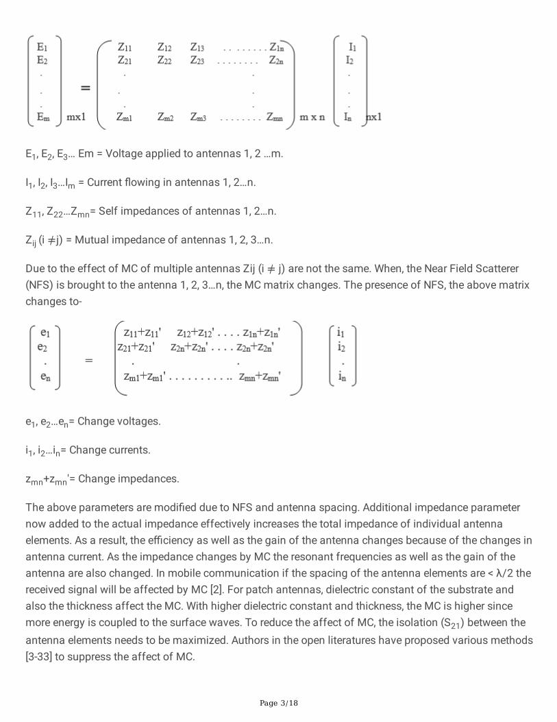
The voltage current relationship for coupled antenna system is written as, E=ZI
Page 3/18
E1, E2, E3… Em = Voltage applied to antennas 1, 2 …m.
I1, I2, I3…Im = Current �owing in antennas 1, 2…n.
Z11, Z22…Zmn= Self impedances of antennas 1, 2…n.
Zij (i ≠j) = Mutual impedance of antennas 1, 2, 3…n.
Due to the effect of MC of multiple antennas Zij (i ≠ j) are not the same. When, the Near Field Scatterer(NFS) is brought to the antenna 1, 2, 3…n, the MC matrix changes. The presence of NFS, the above matrixchanges to-
e1, e2…en= Change voltages.
i1, i2…in= Change currents.
zmn+zmn'= Change impedances.
The above parameters are modi�ed due to NFS and antenna spacing. Additional impedance parameternow added to the actual impedance effectively increases the total impedance of individual antennaelements. As a result, the e�ciency as well as the gain of the antenna changes because of the changes inantenna current. As the impedance changes by MC the resonant frequencies as well as the gain of theantenna are also changed. In mobile communication if the spacing of the antenna elements are < λ/2 thereceived signal will be affected by MC [2]. For patch antennas, dielectric constant of the substrate andalso the thickness affect the MC. With higher dielectric constant and thickness, the MC is higher sincemore energy is coupled to the surface waves. To reduce the affect of MC, the isolation (S21) between theantenna elements needs to be maximized. Authors in the open literatures have proposed various methods[3-33] to suppress the affect of MC.
Page 4/18
In recent years, researchers have proposed various methods such as DGS[3-8], EBG[9-10], parasiticelement[11-13], microstrip resonators[14-20], EMSS[21-24], FSS[25-27], metamaterial structure [28],coupling matrix based band stop �lter[29], meander line [30-31] etc. to suppress the affect of MC betweentwo patch antennas. DGS and EBGs are not very popular techniques as they cannot protect undesirableback radiation. It is seen in the open literatures that the parasitic elements, microstrip resonators,metamaterial structures, coupling matrix based band stop �lter can reduce MC between closely spacedantenna elements.
Recently, a new technique known as Frequency Selective Surface (FSS) has been introduced to suppressMC between very closely spaced antenna elements. Design of FSS is very complicated and most of thecases FSS integrated antennas are erroneous after fabrication. Other than MC, there is one moredrawback of probe feed antenna design for MIMO application. This drawback is the XP radiation assome degree of orthogonally polarized �elds is always associated with the radiating energy [32-33].Researchers suggest that the XP radiation level should be ≤ -20dB for better MIMO antennaperformances.
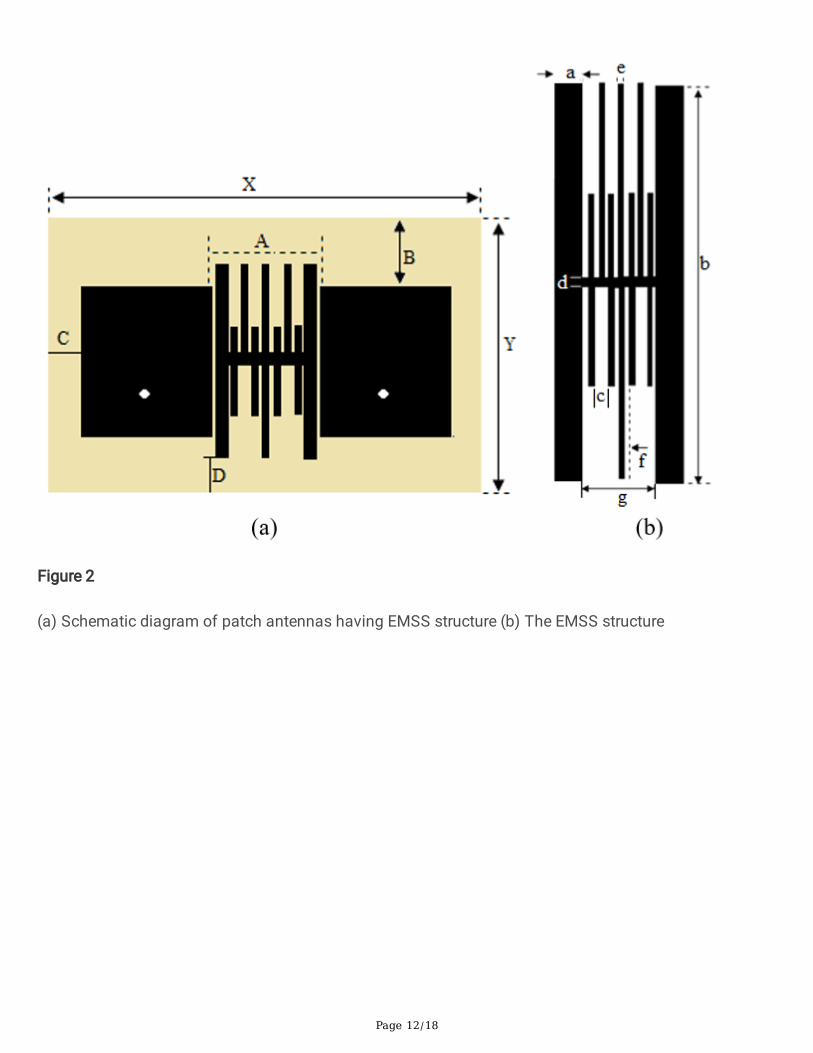
Presently, researchers have introduced EMSS for reducing the affect of MC between the antennaelements. In our design, we have explored a new EMSS structure between two rectangular patch antennasas shown in Figure-3(b).This proposed EMSS created on the substrate between antenna elementseffectively exhibits anti-resonance characteristics at the designed frequency and as a result both MC andXP are suppressed. It has been observed that the proposed EMSS structure does not affect the othercharacteristics of the antenna like return loss, bandwidth, antenna e�ciency and radiation pattern in theprincipal plane.
Design Methodology And ResultsFor this design, we have taken FR4 substrate of dielectric constant 4.4, loss tangent 0.02 and thickness1.6mm.The proposed antenna structure have been simulated using the method of moment (MOM) basedIE3D electromagnetic simulator.
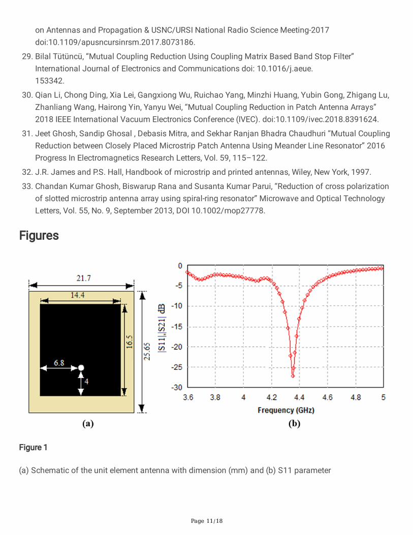
A single element rectangular patch antenna with a co-axial probe feed has been designed as shown inFigure-1(a). The length and width of the antenna is calculated from the standard formulae. The simulatedS11 parameter of single element antenna is shown in Figure-1(b).The result shows that the singleelement antenna resonates at 4.35 GHz with a return loss of -27dB.
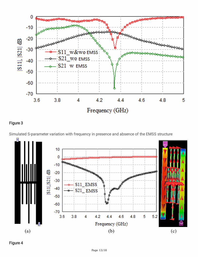
Figure-2 shows that the proposed MIMO antenna is constructed using two identical rectangular patchesintegrated with EMSS structure whose design parameters are given in the Table-1. Centre to centredistance between the antenna elements is taken as 22.1 mm (0.32 λ). The simulated S-parametercharacteristics with and without EMSS structure is shown in Figure-3. From Figure-3, S21 of -17 dBwithout EMSS and -67dB with EMSS is observed. Here, the EMSS creates an indirect electromagneticcoupling path and acts as an anti-resonance mode with the resonance frequency of the excited patch andsuppressed MC signi�cantly.

Page 5/18
The proposed EMSS structure with ports (Figure-4a) is simulated and S-parameter characteristics areshown in Figure-4(b).
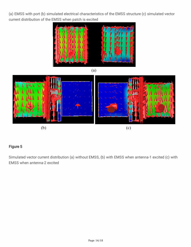
It has been observed from the Figure-4(b) that isolation parameter (S21) of this proposed EMSS structureis much less than -20dB at resonance which can be considered as good reduction of MC for antennadesign. From this Figure, we �nd wide stop band (band gap) characteristics of EMSS structure at 4.35GHz. The EMSS is basically acts as a band stop �lter in this design. When one antenna is excited, theproposed EMSS structure rejects propagation of signals at resonance because of its stop bandcharacteristic. Figure-5 exhibits the reduction of MC using vector current distributions of the antennasand the EMSS. In Figure-5(a), it has been observed that antenna-2 is affected by the MC when theantenna-1 is excited and Figure-5(a) & (b) shows effect of EMSS.
The MC is suppressed in the presence of the EMSS as this creates an oblique coupling path. This helps ingetting a low MC between the antenna elements as shown in Figure-5(b). Same scenario is also observedin Figure-5(c) when antenna-2 is excited as this soft surface suppresses the surface current and near �eldcoupling.
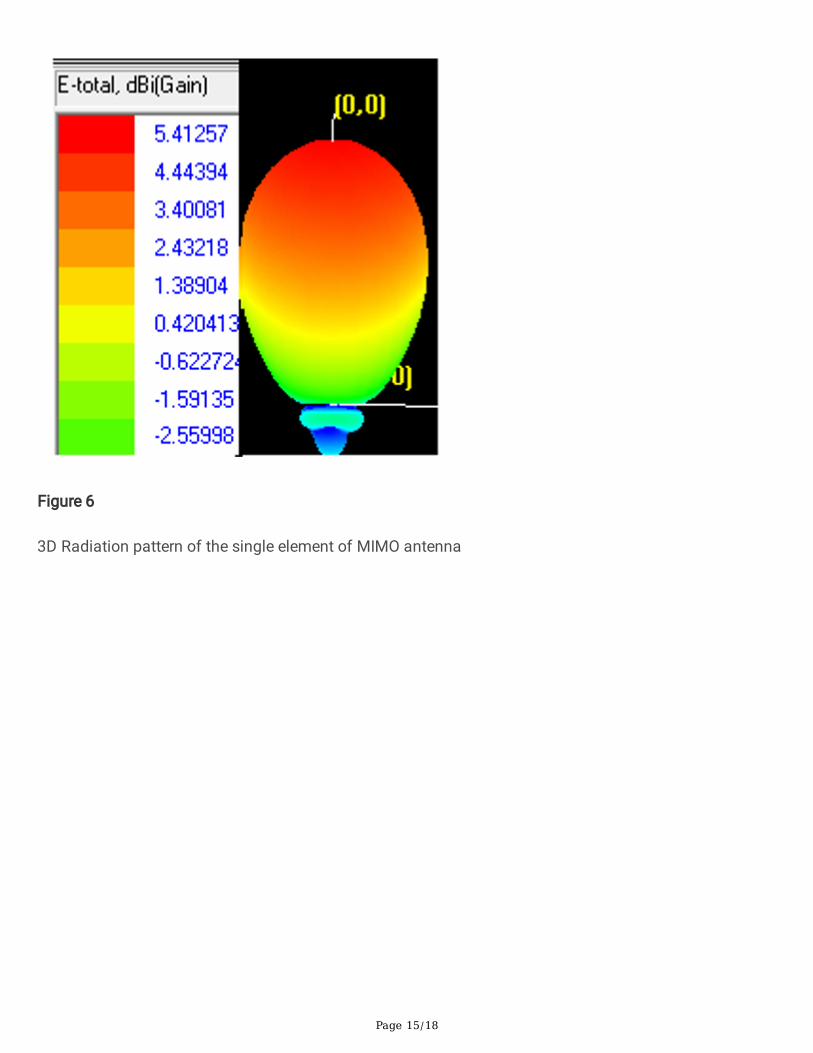
Figure-6 shows the simulated 3D radiation pattern. In this Figure, the gain of the proposed antenna is5.40dBi. Figure-7 shows a graphical representation of co-polar and cross-polar radiation patterns of thesingle element antenna.
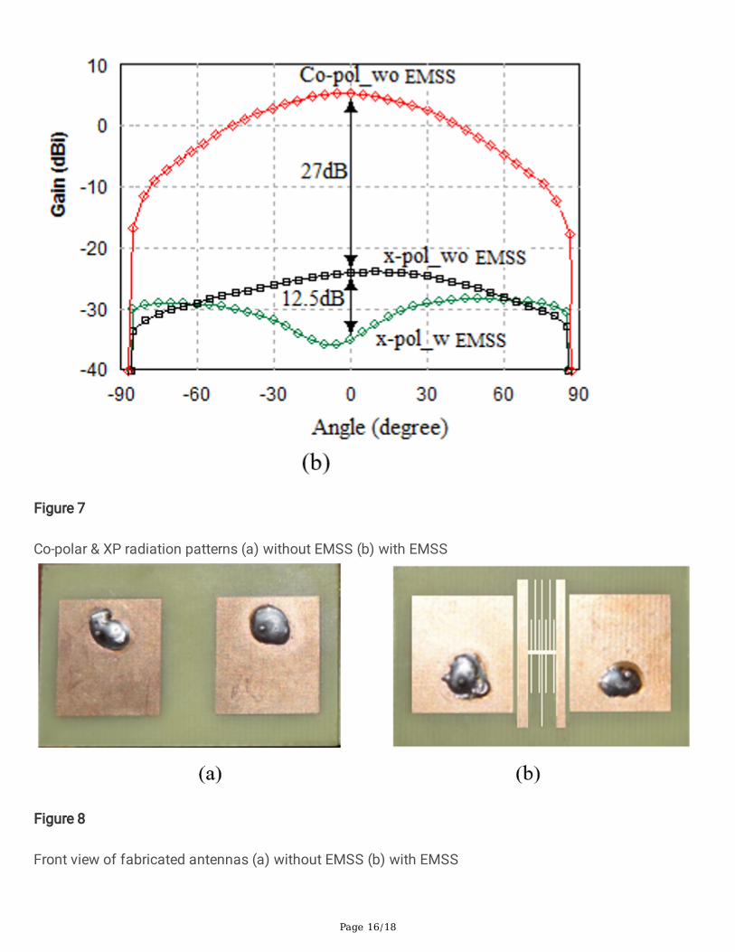
XP radiation degrades antenna radiation pattern in the principal plane. This undesirable radiation needsto minimize for achieving better radiation e�ciency. From Figure-7, it has been observed that thedifference of XP patterns is 12.5 dBi between without and with EMSS.
This proposed work has been compared with other similar works and a comparison table is given below.
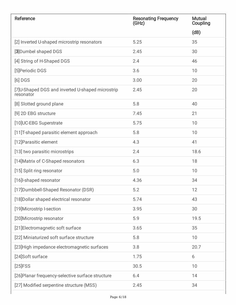
Table-2. Comparison table of performance analysis with other similar works
Page 6/18
Reference Resonating Frequency(GHz)
MutualCoupling
(dB)
[2] Inverted U-shaped microstrip resonators 5.25 35
[3]Dumbel shaped DGS 2.45 30
[4] String of H-Shaped DGS 2.4 46
[5]Periodic DGS 3.6 10
[6] DGS 3.00 20
[7]U-Shaped DGS and inverted U-shaped microstripresonator
2.45 20
[8] Slotted ground plane 5.8 40
[9] 2D EBG structure 7.45 21
[10]UC-EBG Superstrate 5.75 10
[11]T-shaped parasitic element approach 5.8 10
[12]Parasitic element 4.3 41
[13] two parasitic microstrips 2.4 18.6
[14]Matrix of C-Shaped resonators 6.3 18
[15] Split ring resonator 5.0 10
[16]I-shaped resonator 4.36 34
[17]Dumbbell-Shaped Resonator (DSR) 5.2 12
[18]Dollar shaped electrical resonator 5.74 43
[19]Microstrip I-section 3.95 30
[20]Microstrip resonator 5.9 19.5
[21]Electromagnetic soft surface 3.65 35
[22] Miniaturized soft surface structure 5.8 10
[23]High impedance electromagnetic surfaces 3.8 20.7
[24]Soft surface 1.75 6
[25]FSS 30.5 10
[26]Planar frequency-selective surface structure 6.4 14
[27] Modi�ed serpentine structure (MSS) 2.45 34
Page 7/18
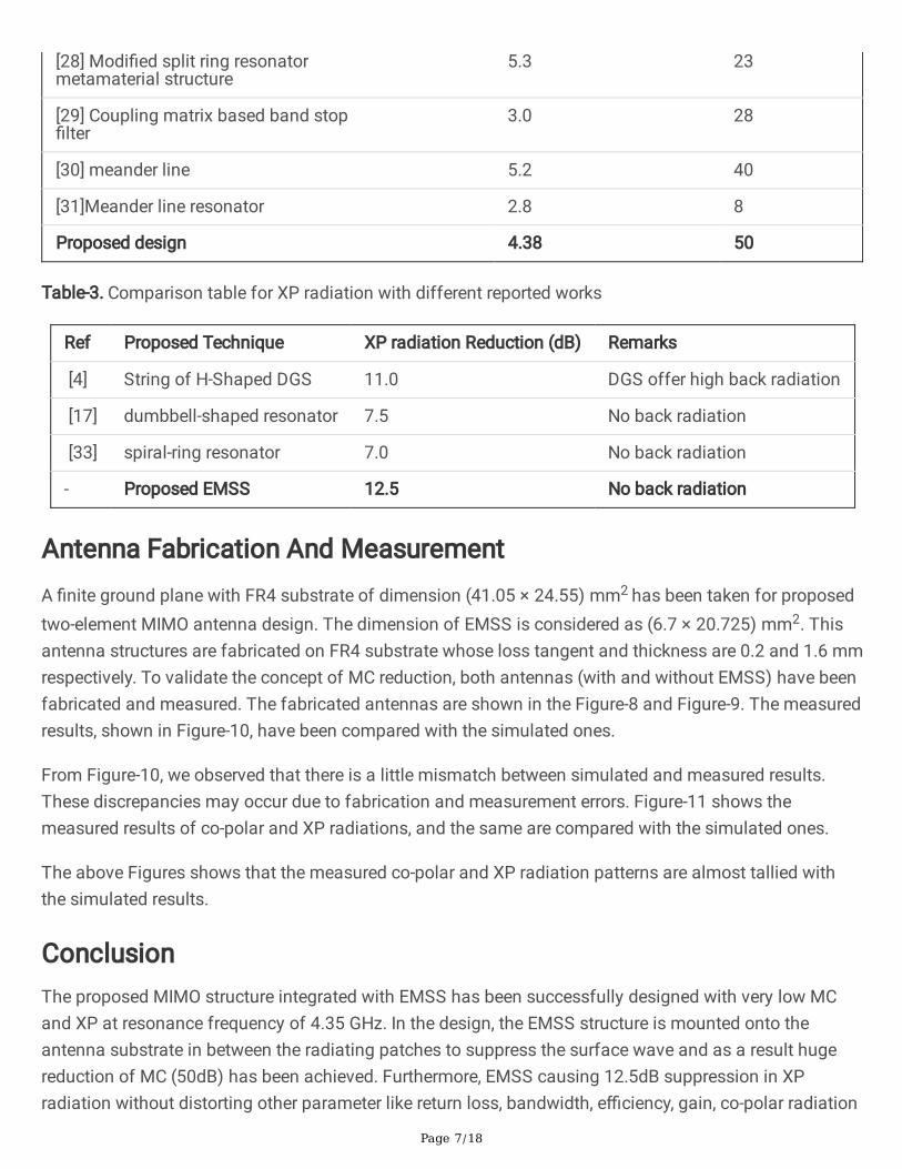
[28] Modi�ed split ring resonatormetamaterial structure
5.3 23
[29] Coupling matrix based band stop�lter
3.0 28
[30] meander line 5.2 40
[31]Meander line resonator 2.8 8
Proposed design 4.38 50
Table-3. Comparison table for XP radiation with different reported works
Ref Proposed Technique XP radiation Reduction (dB) Remarks
[4] String of H-Shaped DGS 11.0 DGS offer high back radiation
[17] dumbbell-shaped resonator 7.5 No back radiation
[33] spiral-ring resonator 7.0 No back radiation
- Proposed EMSS 12.5 No back radiation
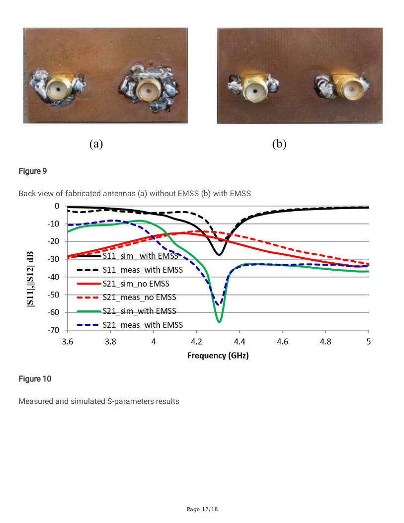
Antenna Fabrication And MeasurementA �nite ground plane with FR4 substrate of dimension (41.05 × 24.55) mm2 has been taken for proposedtwo-element MIMO antenna design. The dimension of EMSS is considered as (6.7 × 20.725) mm2. Thisantenna structures are fabricated on FR4 substrate whose loss tangent and thickness are 0.2 and 1.6 mmrespectively. To validate the concept of MC reduction, both antennas (with and without EMSS) have beenfabricated and measured. The fabricated antennas are shown in the Figure-8 and Figure-9. The measuredresults, shown in Figure-10, have been compared with the simulated ones.
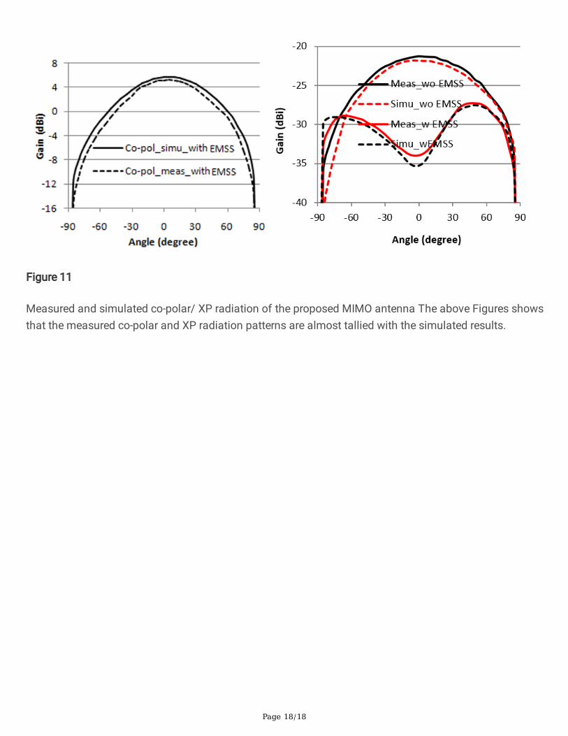
From Figure-10, we observed that there is a little mismatch between simulated and measured results.These discrepancies may occur due to fabrication and measurement errors. Figure-11 shows themeasured results of co-polar and XP radiations, and the same are compared with the simulated ones.
The above Figures shows that the measured co-polar and XP radiation patterns are almost tallied withthe simulated results.
ConclusionThe proposed MIMO structure integrated with EMSS has been successfully designed with very low MCand XP at resonance frequency of 4.35 GHz. In the design, the EMSS structure is mounted onto theantenna substrate in between the radiating patches to suppress the surface wave and as a result hugereduction of MC (50dB) has been achieved. Furthermore, EMSS causing 12.5dB suppression in XPradiation without distorting other parameter like return loss, bandwidth, e�ciency, gain, co-polar radiation

Page 8/18
etc. The proposed MIMO antenna integrated with EMSS achieved a gain of 5.40 dBi at resonance. Thisproposed antenna is suitable for C-band applications like satellite and radar communication.
DeclarationsThe authors like to acknowledge NIT Durgapur and IIEST, Shibpur, India for providing necessary supportduring this research work. This work is original and not submitted for publication elsewhere.
FUNDING
No funding was received for conducting this study.
DISCLOSURE STATEMENT
No potential con�ict of interest was reported by the authors.
DATA TRANSPARENCY
Not applicable
CODE AVAILABILITY
Not applicable
AUTHORS’ CONTRIBUTIONS
All authors contributed to the study conception and design. Material preparation, data collection andanalysis were performed by [Swati Bhattacharjee], [Santimoy Mandal] and [Chandan Kumar Ghosh]. The�rst draft of the manuscript was written by [Swati Bhattacharjee] and all authors commented on previousversions of the manuscript. All authors read and approved the �nal manuscript.
References1. Balanis C. Antenna theory: analysis and design. Hoboken (NJ): Wiley Interscience; 2005.
2. Chandan Kumar Ghosh, “A compact 4-channel microstrip MIMO antenna with reduced mutualcoupling” 2016 International Journal of Electronics andCommunications (AEÜ), Vol.70, pp-873-879, 2016.
3. Lin Teng, Jingrui Pei and Shoulin Yin “Mutual Coupling Optimization of Compact Microstrip ArrayAntenna” Indonesian Journal of Electrical Engineering and Computer Science Vol. 4, No. 3, pp. 538-541, December 2016.
4. Juin Acharjee , Kaushik Mandal , and Sujit Kumar Mandal, “Reduction of Mutual Coupling and CrossPolarization of a MIMO/Diversity Antenna using a String of H-Shaped DGS” AEU-InternationalJournal of Electronics and Communications. doi:10.1016/j.aeue.2018.09.037.

Page 9/18
5. Kun Wei , Jian-Ying Li , Ling Wang , Zi-Jian Xing , Rui Xu, “Mutual Coupling Reduction of MicrostripAntenna Array by Periodic Defected Ground Structures” 2016 IEEE 5th Asia-Paci�c Conference onAntennas and Propagation (APCAP). doi:10.1109/apcap.2016.7843257.
�. Zhaolin Zhang , Kun Wei , Jian Xie , Jianying Li , Ling Wang, “The MIMO Antenna Array with MutualCoupling Reduction and Cross-polarization Suppression by Defected Ground Structures” Radioengineering, Vol. 27, No. 4, December 2018, DOI: 10.13164/re.2018.0969.
7. Chandan K. Ghosh, BappadityaMandal, and Susanta K. Parui “Mutual coupling reductionof a dual-frequency microstrip antenna array by using U-shaped DGS and inverted U- shapedmicrostrip resonator” Progress in Electromagnetic Research C, Vol. 48, 61–68
�. J. OuYang, F. Yang, and Z. M. Wang, “Reducing Mutual Coupling of Closely SpacedMicrostrip MIMO Antennas for WLAN Application” IEEE Antennas and Wireless Propagation Letters,Vol. 10, 2011.
9. Hassan Sajjad, Sana Khan, and Ercument Arvas “Mutual Coupling Reduction in Array Elements UsingEBG Structures” International Applied Computational Electromagnetics Society Symposium - Italy(ACES-2017). doi:10.23919/ropaces.2017.7916410.
10. Hossein Sarbandi Farahani, Mehdi Veysi, Manouchehr Kamyab, and Alireza Tadjalli, “MutualCoupling Reduction in Patch Antenna Arrays Using a UC-EBG Superstrate” IEEE Antennas andWireless Propagation Letters, Vol. 9, 2010.
11. Faizan Faraz, Qinlong Li, Xiaoming Chen, Muhammad Abdullah, Shuai Zhang, Anxue Zhang “MutualCoupling Reduction for Linearly Arranged MIMO Antenna” Cross Strait Quad-Regional Radio Scienceand Wireless Technology Conference (CSQRWC-2019). doi:10.1109/csqrwc.2019.8799266.
12. Emadeddin, A., Shad, S., Rahimian, Z., & Hassani, H. R. “High mutual coupling reduction betweenmicrostrip patch antennas using novel structure”. AEU - International Journal of Electronics andCommunications (2017)., 71, 152–156. doi:10.1016/j.aeue.2016.10.017.
13. Xu-bao Sun , Mao-yong Cao, “Mutual coupling reduction in an antenna array by using two parasiticmicrostrips” AEU - International Journal of Electronics and Communications, 74, 1–4.doi:10.1016/j.aeue.2017.01.013.
14. Raghad Ghalib, Saadallah Alsultan and Gölge Ögücü, Yetkin “Mutual Coupling Reduction of E-Shaped MIMO Antenna with Matrix of C-Shaped Resonators HindawiInternational Journal of Antennas and Propagation Volume 2018, Article ID 4814176, DOI-10.1155/2018/4814176.
15. Bait-Suwailam, M. M., Siddiqui, O. F., &Ramahi, O. M. “Mutual Coupling Reduction between MicrostripPatch Antennas Using Slotted-Complementary Split-RingResonators”. IEEE Antennas and Wireless Propagation Letters, 9, 876–878. 2010.
1�. Swati Bhattacharjee, Chandan Kumar Ghosh “Reduction of Mutual Coupling between two adjacentMicrostrip antennas using I-shaped Resonators” IEEE International conference on advent trends inMultidisciplinary Research and Innovation (ICATMRI-2020).

Page 10/18
17. Chandan Kumar Ghosh, R. Hazra, A. Biswas, A.K. Bhattachrjee, and S.K. Parui , “Suppression ofcrosspolarization and mutual coupling between dual trace dual column coaxial microstrip arrayusing dumbbell-shaped resonator” Microwave and Optical Technology Letters / Vol. 56, No.9,PP.2182-2186,September 2014, DOI 10.1002/mop.28531.
1�. Santimoy Mandal and Chandan Kumar Ghosh, “Reduction of the Mutual Couplingin Patch Antenna Arrays Based on Dollar Shaped Electrical Resonator” Lecture notes on ElectricalEngineering 602, proceeding of 2nd international conference on Communication, Devices andComputing ICCDC 2019, Springer, p.p-71-76.
19. Chandan Kumar Ghosh and Susanta Kumar Parui “Reduction of mutual coupling between E-shapedmicrostrip antennas by using a simple microstrip I-section” Microwaveand Optical Technology Letters Vol. 55, No. 11, 2013.
20. Chandan Kumar Ghosh ,ManishPratap, Rahul Kumar, Saurabh Pratap “Mutual Coupling Reduction ofMicrostrip MIMO Antenna Using Microstrip Resonator “WirelessPersonal Communications,2020, DOI 10.1007/s11277-020-07138-z.
21. Chandan Kumar Ghosh and Sourav Moitra“Study of decoupling between patch elements ofmicrostrip array using electromagnetic soft surface” Journal of Electromagnetic wavesand applications,Vol.32,Issue-9,PP-1126-1135, 17 Jan 2018.
22. S. Abushamleh, H. Al-Rizzo, A. Abbosh,Ahmed A. Kishk “Mutual coupling reduction between twopatch antennas using a new miniaturized soft surface structure”. IEEE AP-S Dig. 2013. p. 1822–1823.
23. Mohammad Tariqul Islam and Md. Shahidul Alam, “Design of High Impedance ElectromagneticSurfaces for Mutual Coupling Reduction in Patch Antenna Array” Materials 2013, 6, 143-155;doi:10.3390/ma6010143.
24. Óscar Quevedo-Teruel, Luis Inclán-Sánchez, and Eva Rajo-Iglesias, “Soft Surfaces for ReducingMutual Coupling Between Loaded PIFA Antennas” IEEE Antennas and Wireless Propagation Letters,9, 91–94. doi:10.1109/lawp.2010.2043632.
25. M. Akbari, M.M. Ali, M. Farahani, A.R. Sebak and T. Denidni, “Spatially mutual coupling reductionbetween CP-MIMO antennas using FSS superstrate” ELECTRONICS LETTERS 13th April 2017 Vol. 53No. 8 pp. 516–518.
2�. Ehsan Beiranvand, Majid Afsahy and Vahid Sharbati, “Reduction of the mutual coupling in patchantenna arrays based on EBG by using a planar frequency-selective surface structure” InternationalJournal of Microwave and Wireless Technologies, doi:10.1017/S1759078715001440.
27. Arun, H., Sarma, A. K., Kanagasabai, M., Velan, S., Raviteja, C., & Alsath, M. G. N. “Deployment ofModi�ed Serpentine Structure for Mutual Coupling Reduction in MIMO Antennas”. IEEE Antennasand Wireless Propagation Letters (2014)., 13, 277–280. doi:10.1109/lawp.2014.2304541.
2�. Kai Yu, Xiaoguang Leo Liu,Yingsong Li “Mutual Coupling Reduction of Microstrip Patch AntennaArray Using Modi�ed Split Ring Resonator Metamaterial Structures” IEEE International Symposium
Page 11/18
on Antennas and Propagation & USNC/URSI National Radio Science Meeting-2017doi:10.1109/apusncursinrsm.2017.8073186.
29. Bilal Tütüncü, “Mutual Coupling Reduction Using Coupling Matrix Based Band Stop Filter”International Journal of Electronics and Communications doi: 10.1016/j.aeue.153342.
30. Qian Li, Chong Ding, Xia Lei, Gangxiong Wu, Ruichao Yang, Minzhi Huang, Yubin Gong, Zhigang Lu,Zhanliang Wang, Hairong Yin, Yanyu Wei, “Mutual Coupling Reduction in Patch Antenna Arrays”2018 IEEE International Vacuum Electronics Conference (IVEC). doi:10.1109/ivec.2018.8391624.
31. Jeet Ghosh, Sandip Ghosal , Debasis Mitra, and Sekhar Ranjan Bhadra Chaudhuri “Mutual CouplingReduction between Closely Placed Microstrip Patch Antenna Using Meander Line Resonator” 2016Progress In Electromagnetics Research Letters, Vol. 59, 115–122.
32. J.R. James and P.S. Hall, Handbook of microstrip and printed antennas, Wiley, New York, 1997.
33. Chandan Kumar Ghosh, Biswarup Rana and Susanta Kumar Parui, “Reduction of cross polarizationof slotted microstrip antenna array using spiral-ring resonator” Microwave and Optical TechnologyLetters, Vol. 55, No. 9, September 2013, DOI 10.1002/mop27778.
Figures
Figure 1
(a) Schematic of the unit element antenna with dimension (mm) and (b) S11 parameter
Page 12/18
Figure 2
(a) Schematic diagram of patch antennas having EMSS structure (b) The EMSS structure
Page 13/18
Figure 3
Simulated S-parameter variation with frequency in presence and absence of the EMSS structure
Figure 4
Page 14/18
(a) EMSS with port (b) simulated electrical characteristics of the EMSS structure (c) simulated vectorcurrent distribution of the EMSS when patch is excited
Figure 5
Simulated vector current distribution (a) without EMSS, (b) with EMSS when antenna-1 excited (c) withEMSS when antenna-2 excited
Page 15/18
Figure 6
3D Radiation pattern of the single element of MIMO antenna
Page 16/18
Figure 7
Co-polar & XP radiation patterns (a) without EMSS (b) with EMSS
Figure 8
Front view of fabricated antennas (a) without EMSS (b) with EMSS
Page 17/18
Figure 9
Back view of fabricated antennas (a) without EMSS (b) with EMSS
Figure 10
Measured and simulated S-parameters results
Page 18/18
Figure 11
Measured and simulated co-polar/ XP radiation of the proposed MIMO antenna The above Figures showsthat the measured co-polar and XP radiation patterns are almost tallied with the simulated results.