Ancillary Services supplied to the grid: the case of Thisvi …€¦ · · 2013-07-31generator...
21
Ancillary Services supplied to the grid: the case of Thisvi CCGT power plant (Greece) Claudio Cavandoli, Alessandro Crippa 27/06/2012 – pag. 1 Ancillary Services supplied to the grid: the case of Thisvi CCGT power plant (Greece) Claudio Cavandoli, Alessandro Crippa Edison S.p.A. Engeneering Department
Transcript of Ancillary Services supplied to the grid: the case of Thisvi …€¦ · · 2013-07-31generator...

Ancillary Services supplied to the grid: the case of Thisvi CCGT power plant (Greece) Claudio Cavandoli, Alessandro Crippa 27/06/2012 – pag. 1
Ancillary Services supplied to the grid: the case of Thisvi CCGT power plant (Greece)
Claudio Cavandoli, Alessandro Crippa Edison S.p.A. Engeneering Department

Ancillary Services supplied to the grid: the case of Thisvi CCGT power plant (Greece) Claudio Cavandoli, Alessandro Crippa 27/06/2012 – pag. 2
1. Introduction Elpedison Power (a Joint Venture Company owned/controlled jointly by Edison S.p.A. and Hellenic Petroleum) owns and operates since December 2010 a 421.6 MW Combined Cycle Power Plant located in Thisvi (Beotia prefecture, Greece). The realization of the plant has been carried out by THISVI JV, a Joint Venture between Edison (65%) and Aktor (35%) under an EPCM contract. The power plant erection (earthworks) has started in June 2008; commissioning and testing activities (including tests requested by the Greek grid operator HTSO in order to achieve the “commercial operation”) have been concluded in November 2010, while handover to the final Customer (Elpedison Power) has been completed in December 2010. Edison Engineering department and Aktor have managed the Engineering, Procurement, Construction and Commissioning/Testing of the plant on a “shopping around” basis. The main equipment were purchased to Ansaldo Energia (GT and ST), Nooter Eriksen (HRSG) and GEA (ACC). The combined cycle has been designed in order to be a fully flexible plant (daily start and stop) and in full compliance with European and Greek regulations. In particular it is highlighted that the Greek Grid Code requirement in terms of primary frequency regulation contribution is 3% of Gross Registered Capacity to be delivered to the grid within 30 seconds from the disturbance occurrence [1]. Given the high contribution requested and the GT allowable loading gradient (characteristic of the machine) it is not possible to fulfil the requirement with the GT contribution only. For this reason, a specific frequency regulation procedure (which foresees, in addition to the GT load increase, a ST contribution through the HP control valve) has been developed, dynamically simulated, implemented and tested. The article describes the modifications with respect to the “combined cycles standard operating procedures” that has been necessary to implement in order to fulfil the Greek Grid Code requirements in terms of primary frequency regulation response and the results obtained during the relevant tests.

Ancillary Services supplied to the grid: the case of Thisvi CCGT power plant (Greece) Claudio Cavandoli, Alessandro Crippa 27/06/2012 – pag. 3
2. Plant description THISVI C.C.P.P. is based on a “multi-shaft” arrangement (GT & ST with dedicated generator and step-up transformer), air cooled condenser, with an air insulated electrical substation. The Gas Turbine can be operated both on natural gas (normal operation) and on diesel oil (only for 10 days/year, in emergency conditions as requested by the authorization documents). The Power Island is composed by the following main equipment: • GAS TUBINE: Ansaldo Energia AE94.3A.4 (275 MW ISO) • STEAM TURBINE: Ansaldo Energia MT (146 MW ISO) • STEAM GENERATOR: Nooter Eriksen
(3 pressure levels + RH with post-firing) • AIR CONDENSER: GEA Energietechnik (21 fans) The Heat Recovery Steam Generator is equipped with a supplementary firing system (approx. 33 MWth duty) necessary to meet the gross capacity specified in the authorization process (421.6 MW, ISO conditions). All the auxiliary systems, necessary for correct and safe operation of the plant, have been designed and installed (water treatment, gas compression/reduction station, compressed air, diesel oil unloading and storage, auxiliaries cooling system, fire-fighting systems, HVAC etc.). In the following figure, a picture of the completed power plant is presented.
Figure 2.1 – Plant Front View
3. Greek grid code primary frequency regulation requirements According to the Greek Grid Code, The Unit must be able to fulfil the requirements in terms of Primary Control Reserve (indicated in articles 125 and 275) [1].

Ancillary Services supplied to the grid: the case of Thisvi CCGT power plant (Greece) Claudio Cavandoli, Alessandro Crippa 27/06/2012 – pag. 4
The Grid Code (Article 275) defines, for thermal Power Plants with a Registered Capacity of at least 100 MWe, the following requirements [1]: 1. Each Generation Unit must have primary frequency control capability; 2. The operating reserve shall be not less than 3% of the registered capacity in the
range between 50% and 97% of the registered capacity; 3. The operating reserve in the range between 97% and 100% shall be not less than
that indicated by a straight line with fixed slope from 3% of registered capacity at 97% output and 0% at full load;
4. The production license holder must be capable of activating, within 30 seconds, the total primary operating reserve and of maintaining supply for at least 15 minutes;
5. The primary operating reserve must be available again 15 minutes after activation. Considering a Registered Capacity of 421.6 MWe in post-firing mode, the operating reserve required between 50% and 97% CCPP load corresponds to 12.6 MWe/30sec. Between 97% and 100% power plant load, the contribution required by the Code is represented by the curve showed in Figure 3.1:
Load variation Vs plant load
0
2
4
6
8
10
12
14
95% 96% 97% 98% 99% 100%
Power Plant Load
Grid required load variation MW/30s
Figure 3.1 – Contribution required by the Greek Grid Code
4. Requirements impacts on control strategy Most of the Combined Cycle Power Plants normally fulfil the primary frequency regulation grid requirements with the gas turbine contribution only. In such cases, the requested contribution is provided by the Gas Turbine (either operating it slightly below the relevant Base Load, or over-firing it when possible), with the Steam turbine following in “sliding pressure”. In Thisvi case, given the high contribution required and the load ramp-rates allowed by the GT (see below details) such operating mode is not enough to meet the requirements. In particular, the main issue is that the GT power output ramp-rate is reduced at high

Ancillary Services supplied to the grid: the case of Thisvi CCGT power plant (Greece) Claudio Cavandoli, Alessandro Crippa 27/06/2012 – pag. 5
loads (from approx. 98% of the Hot Base Load), thus not allowing to manage the primary frequency regulation requirements with the GT only.
GAS TURBINE LOADING CURVES
70
75
80
85
90
95
100
60 65 70 75 80 85 90 95 100
Power Output [%]
TO
T, T
OM
F -
[%
]
01234567891011121314151617181920212223242526272829303132333435
Lo
ad R
amp
Rat
e [M
W/m
in]
Turbine Exhaust Mass Flow Turbine Outlet Temperature Load Ramp Rate (FR) Load Ramp Rate (NO) Figure 4.1 – Gas Turbine Loading Curves
As shown in the graphic of Figure 4.1, when the GT approaches the so called Cold Base Load (98% of Hot Base Load), the loading ramp (both in normal operation and in frequency regulation) is reduced by one half. In particular, during normal operation the allowable load gradients are: • 13 MW/min for GT load between minimum load and 98% of hot base
load • 6.5 MW/min for GT load between 98% and 100% of hot base load In case the load variation request is generated by a frequency deviation, the allowable load gradients are automatically increased to the following values: • 24 MW/min for GT load between minimum load and 98% of hot base
load • 13 MW/min for GT load between 98% and 100% of hot base load From the above considerations, it clearly appears that it is not possible to fulfil the Greek Grid Code requirements in terms of Primary frequency regulation relying only on the Gas Turbine contribution, when the Gas Turbine load approaches its maximum value. In order to overcome the above described limit, the applied solution is to over-pressurize the HRSG HP and IP sections (using the ST HP control valve and the so-called bridge valve, see following figures), in order to accumulate the necessary energy to be transiently drawn to the steam turbine as soon as a frequency disturbance is detected.

Ancillary Services supplied to the grid: the case of Thisvi CCGT power plant (Greece) Claudio Cavandoli, Alessandro Crippa 27/06/2012 – pag. 6
Figure 4.2 – ST HP Control Valve used for pressurization
Figure 4.3 – IP SH “Bridge Valve”
In this way, the Steam Turbine actively participates (quickly opening the HP control valve) to the primary frequency regulation, providing the necessary contribution during the transient. The HRSG design pressure has been defined according to the operating cases considered in the dynamic analysis described in paragraph 6. The “bridge valve” located at the IP superheater outlet is used to keep slightly pressurized the IP steam drum in order to prevent steam back-flow during the transient (which would limit the contribution of the Steam Turbine IP section). The ST contribution is limited in time, due to the transient nature of the over-pressurization. In order to maintain it for the necessary time, the GT load and the supplementary firing thermal input must be increased during the transient in order to limit the natural de-pressurization of the system. The next three paragraphs describe in detail the control strategy implemented, the dynamic simulation results/optimization and finally the on-site tests results, performed at the presence of HTSO representative in order to assess the full compliance of the plant to the Greek Grid Code requirements.

Ancillary Services supplied to the grid: the case of Thisvi CCGT power plant (Greece) Claudio Cavandoli, Alessandro Crippa 27/06/2012 – pag. 7
5. Plant frequency regulation procedure One goal of the Plant Load and Frequency regulation procedure is to keep the Manufacturer standard speed / load control loop both for GT and ST. During “normal” operation the GT follows a load set point, while the ST will follow a inlet pressure set point corresponding to HP ST inlet valve wide open, i.e. natural sliding pressure operation. To accomplish this, the Master Load Control calculates: • The Load Set Point requested to the Gas Turbine Control System, as the total
Plant Net Power set point minus the power produced by the steam turbine, within Minimum and Maximum Plant Load Limits which ensure, in case of frequency disturbs on the Grid, the availability of the Plant Primary Power Reserve.
• The pressure set point to the HP ST inlet throttle valve, via the Steam Turbine
Control System, as a function of actual HP steam flow, in order to avoid losses due to lamination on the relative steam circuits; the pressure on the HP and IP steam headers varies according to inlet flow rate with a linear function, characteristic of the machine, until the maximum load conditions are reached.
• HRSG supplementary firing system set point, as a linear function of GT load. In this conditions the ST follows and reacts to the load of GT, (so-called “Steam Turbine follows” operating mode) and do not supply extra-power in primary frequency control: Primary frequency response is given via the GT contribution only. The advantage of this operating mode, through GT & ST standard control loops, is that the HP SH pressure is maintained by the ST inlet control valve and the HRSG supplementary firing will work in a simple open loop; such configuration allows to avoid plant load ramp rate reduction while in operation at fired load: as far as the HRSG burners are operated according to GT load, the relevant impact on plant load variation speed is negligible (the flexibility is equivalent to an unfired power plant). When instead the steam turbine is operated in frequency participation mode, HP steam header is controlled in modified sliding pressure (fixed pressure increase of +10 bar on natural sliding pressure, following steam flow-rate), up to the maximum operating pressure; when this value is reached, the header is then operated at maximum operating pressure (constant pressure). In the graphic of Figure 5.1 the ST natural sliding pressure curve (linearized) vs. the modified sliding curve are shown: The ST reacts to Grid frequency disturbs greater than 20 mHz (dead-band), in order to avoid unnecessary depressurization of the headers and fluctuations. The ST Active Power response will be proportional to the frequency disturbance, according to the defined droop control; in case the request from the Grid is maximum, the STCS will open 100% the control valve, thus providing all the accumulated power due to pressurization. Table 5.1 summarizes the operating steps:
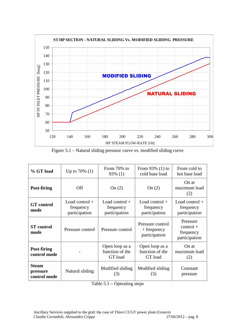
Ancillary Services supplied to the grid: the case of Thisvi CCGT power plant (Greece) Claudio Cavandoli, Alessandro Crippa 27/06/2012 – pag. 8
ST HP SECTION - NATURAL SLIDING Vs. MODIFIED SLIDING PRESSURE
50
60
70
80
90
100
110
120
130
140
150
120 140 160 180 200 220 240 260 280 300
HP STEAM FLOW-RATE [t/h]
HP
ST
IN
LET
PR
ES
SU
RE
[b
arg
]
Figure 5.1 – Natural sliding pressure curve vs. modified sliding curve
% GT load Up to 70% (1) From 70% to
93% (1) From 93% (1) to cold base load
From cold to hot base load
Post-firing Off On (2) On (2) On at
maximum load (2)
GT control mode
Load control + frequency
participation
Load control + frequency
participation
Load control + frequency
participation
Load control + frequency
participation
ST control mode
Pressure control Pressure control Pressure control
+ frequency participation
Pressure control + frequency
participation
Post-firing control mode
- Open loop as a function of the
GT load
Open loop as a function of the
GT load
On at maximum load
(2)
Steam pressure control mode
Natural sliding Modified sliding
(3) Modified sliding
(3) Constant pressure
Table 5.1 – Operating steps

Ancillary Services supplied to the grid: the case of Thisvi CCGT power plant (Greece) Claudio Cavandoli, Alessandro Crippa 27/06/2012 – pag. 9
Referring to Table 5.1, they are important to mention the following notes:
1. 70% GT load is defined in order to maintain the power reserve and fulfill the time requirements due to the primary frequency control, while maintaining adequate ramp rates for secondary frequency control participation; 93% means that, considering the load rate change from 24MWe/minute to 13 MWe/minute at 98% GT load, the gas turbine maintains the required load margin (3% plant load i.e. 12.6 MWe) for the primary frequency control
2. Post-firing load will follow GT load, from 0% with GT at 70% load, to 100% with GT at cold base load; note: post firing maximum load is limited to its maximum load (MWth) or maximum exhaust gases temperature (°C), whichever is reached first
3. HP steam header pressurization until +10 bar (fixed value) from natural sliding pressure at the actual ST load, controlled through HP ST inlet control valve up to the maximum operating pressure (see fig.5.1); HRSG IP steam section pressurization until 2 bar (fixed value) pressure drop measured between IP SH outlet pressure and IP drum pressure
The following actions will occur due to ST response to frequency variation, with the ST participation to Plant primary frequency regulation activated:
1. As the frequency disturb is detected and it is higher than the ST frequency control loop dead band, the ST Control System (STCS) activates the frequency response. While frequency response is active, the STCS inlet pressure controller is set in tracking mode with set point equal to pressure actual value;
2. If the “frequency control on” signal from STCS is activated, the Master Load Control function open the IP bridge valve and set the IP steam delta pressure set point in tracking mode on actual delta pressure, to allow bumpless transition as frequency is restored; also the Master Load Control set the HP steam pressure set point in tracking mode on actual HP pressure, to allow bumpless transition as frequency is restored;
3. As the frequency disturb reduces below dead band, the ST pressure controller re-insert; the pressure set-point of the DCS pressure controller is set at the actual value, measured from ST pressure transmitter, in order to get bumpless changes during the transient;
4. As the STCS inlet pressure controller is enabled again the ST will follow the HP steam pressure set point elaborated by Master Load Control, starting headers re-pressurization with ramp-rates;
5. As also the GT has reacted to frequency variation according to the defined k∆f, the combined action of GT and ST guarantee the correct response of the Power Plant, thus respecting the Grid Code requirements.
6. Dynamic simulation In order to evaluate in advance the plant response to a frequency disturbance and with the aim to optimize the above described procedure as well as the involved control system logics and parameters, a dynamic simulation study of the plant has been developed together with the Politecnico di Milano University and ACT Solutions.

Ancillary Services supplied to the grid: the case of Thisvi CCGT power plant (Greece) Claudio Cavandoli, Alessandro Crippa 27/06/2012 – pag. 10
The plant and control system model was developed in the Object-Oriented Modelica language by using the Dymola translator, and is composed of the following main sub-systems: • A process model of the relevant parts of entire BOP (water, steam, flue gas, PF
combustor) • a model of the gas turbine (GT) with the aim of reproducing its power generation
response so as to present realistic boundary conditions at the post-firing chamber inlet (on the plant model side) and to the control system;
• a model of the steam turbine (ST) with the aim of reproducing its power generation response and main process parameters;
• the boundary conditions impressed by the electric system, limiting the scope to the behaviour of the generator frequency;
• a partial model of the control system, integrating the necessary features of GT/ST controllers and plant DCS.
OVERALL MODEL PLANT MODEL
Figure 6.1 – Dynamic Simulation Model
Prior to the simulations, the model was aligned to the available data (resulting from steady state simulations). Concerning the boundary conditions representing the electrical network, in absence of detailed information, a conservative approach has been followed: a frequency “step” of the maximum allowable value (-2.5 Hz in 0.5 sec) without return to the set point value has been considered. The main systems involved in the frequency regulation simulation (which have been modelled in detail) are: • GT and ST governors (which have been modelled as per Ansaldo data) • Supplementary Firing, Bridge Valve and HP section pressurization management (modelled as indicated in the previous paragraph)

Ancillary Services supplied to the grid: the case of Thisvi CCGT power plant (Greece) Claudio Cavandoli, Alessandro Crippa 27/06/2012 – pag. 11
The main results of the simulations are reported in the graphics of Figure 6.2. They show that the proposed control strategy (adequately fine tuned at site) allows the fulfilment of the Greek Grid Code requirements.
Figure 6.2 – Dynamic Simulation Results

Ancillary Services supplied to the grid: the case of Thisvi CCGT power plant (Greece) Claudio Cavandoli, Alessandro Crippa 27/06/2012 – pag. 12
7. Control system configuration In the Figure 7.1 and Figure 7.2, the schematic diagram of the control system and the relevant DCS video page are reported.
Figure 7.1 – Control System schematic diagram
Figure 7.2 – Control System video page

Ancillary Services supplied to the grid: the case of Thisvi CCGT power plant (Greece) Claudio Cavandoli, Alessandro Crippa 27/06/2012 – pag. 13
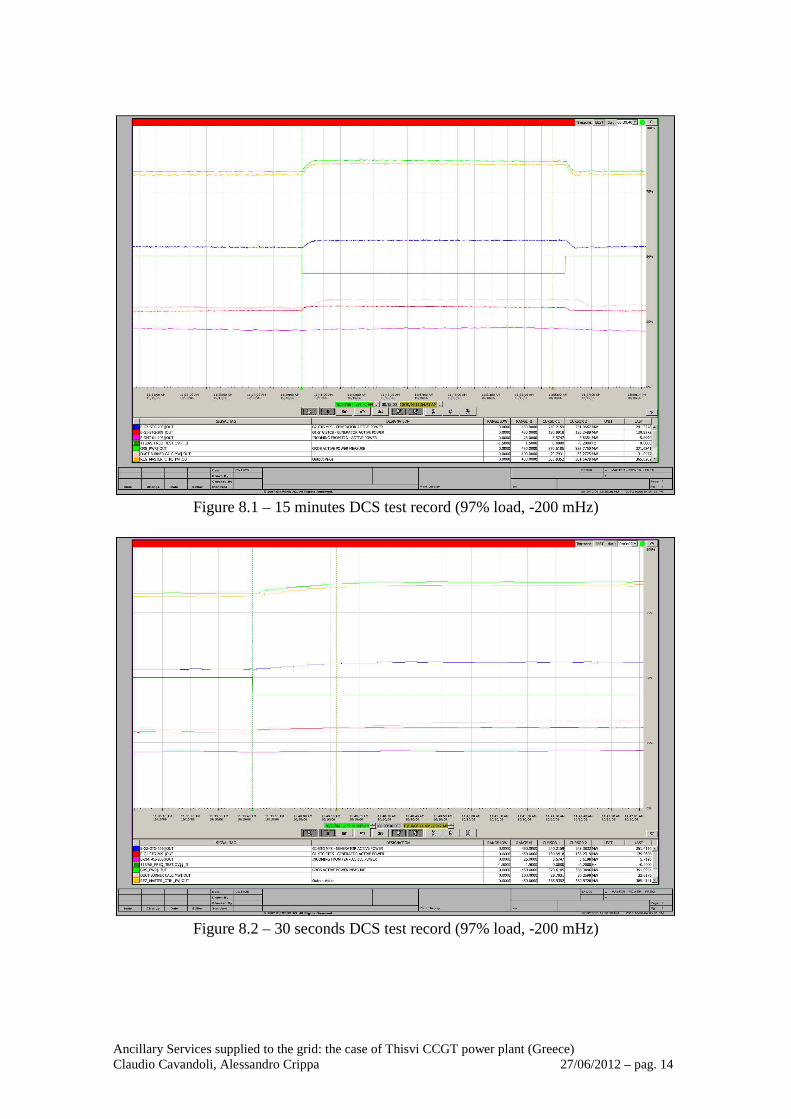
8. Tests results On 06/10/2010, at the presence of HTSO representative, the following tests have been carried out in order to assess Thisvi Power Plant full compliance with the Greek Grid Code requirements in terms of Primary Frequency Contribution: • Plant at 97% load: Frequency error injection of ± 200 mHz maintained for 15
min • Plant at 90% load: Frequency error injection of ± 200 mHz maintained for 15
min • Plant at 80% load: Frequency error injection of ± 200 mHz maintained for 15
min • Plant at 60% load: Frequency error injection of ± 200 mHz maintained for 15
min The tests can be considered successful if the following conditions are satisfied: • After 30 seconds from disturbance activation the sum of GT and ST gross power
output has been increased of at least 12.6 MW; • The increased power average value is maintained for 15 minutes from the
disturbance activation. In the Table 8.1 the results of the performed tests are reported:
Plant Load [%]
Frequency Error [mHz]
Primary Frequency Contribution [MW]
30 seconds 15 minutes 97 % - 200 + 15.0 + 16.9 97 % + 200 - 13.5 - 13.8 90 % - 200 + 11.6 + 15.3 90 % + 200 - 14.0 - 12.9 80 % - 200 + 13.7 + 13.5 80 % + 200 - 16.4 - 16.2 60 % - 200 + 15.5 + 14.2 60 % + 200 - 16.0 - 13.0
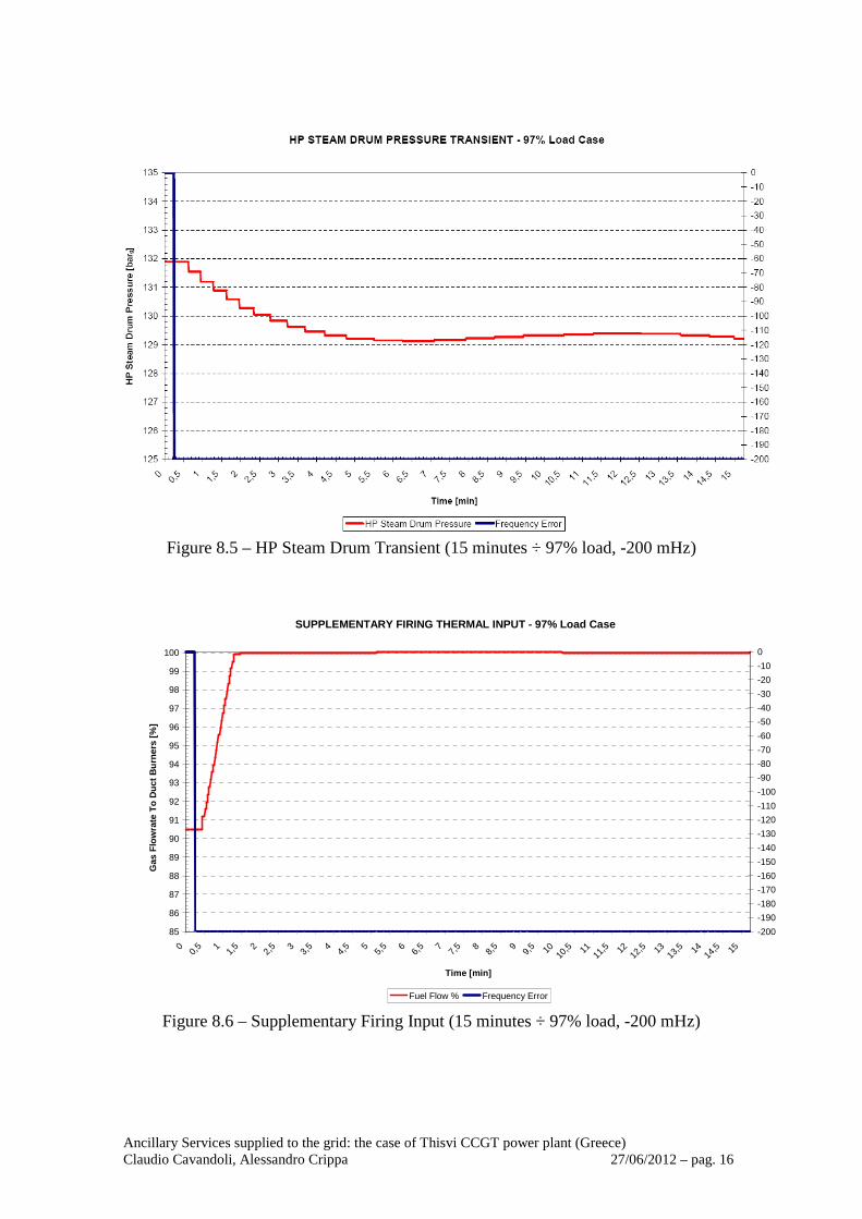
Table 5.1 – Performed test results Considering the accuracy of the instruments (field instrumentation) and the discrete nature of the DCS readings, all the tests have been considered successful. In the graphics of Figure 8.1, 8.2, 8.3, 8.4, 8.5, 8.6, the main parameters recorded during the 97% load test with frequency error injection of -200 mHz (which is the “worst case” test) are reported.
Ancillary Services supplied to the grid: the case of Thisvi CCGT power plant (Greece) Claudio Cavandoli, Alessandro Crippa 27/06/2012 – pag. 14
Figure 8.1 – 15 minutes DCS test record (97% load, -200 mHz)
Figure 8.2 – 30 seconds DCS test record (97% load, -200 mHz)

Ancillary Services supplied to the grid: the case of Thisvi CCGT power plant (Greece) Claudio Cavandoli, Alessandro Crippa 27/06/2012 – pag. 15
Figure 8.3 – Gas Turbine Frequency Response (15 minutes ÷ 97% load, -200 mHz)
Figure 8.4 – Steam Turbine Frequency Response (15 minutes ÷ 97% load, -200 mHz)
Ancillary Services supplied to the grid: the case of Thisvi CCGT power plant (Greece) Claudio Cavandoli, Alessandro Crippa 27/06/2012 – pag. 16
Figure 8.5 – HP Steam Drum Transient (15 minutes ÷ 97% load, -200 mHz)
SUPPLEMENTARY FIRING THERMAL INPUT - 97% Load Case
85
86
87
88
89
90
91
92
93
94
95
96
97
98
99
100
00,
5 11,
5 22,
5 33,
5 44,
5 55,
5 66,
5 77,
5 88,
5 99,
5 1010
,5 1111
,5 1212
,5 1313
,5 1414
,5 15
Time [min]
Gas
Flo
wra
te T
o D
uct
Bu
rner
s [%
]
-200
-190
-180
-170
-160
-150
-140
-130
-120
-110
-100
-90
-80
-70
-60
-50
-40
-30
-20
-10
0
Fuel Flow % Frequency Error
Figure 8.6 – Supplementary Firing Input (15 minutes ÷ 97% load, -200 mHz)
Ancillary Services supplied to the grid: the case of Thisvi CCGT power plant (Greece) Claudio Cavandoli, Alessandro Crippa 27/06/2012 – pag. 17
9. Greek electrical grid code requirements: conclusions As a general statement, the ST participation to the frequency regulation can be considered an effective method to share the regulating contribution between the GT and the ST, thus reducing the thermal stresses on the GT and the necessary load reduction (and the consequent ST load reduction in combined cycle operation). In Thisvi case moreover, due to the high contribution requested and to the GT allowable loading gradient, the ST participation is necessary to meet the Greek Grid Code Requirements. As shown in the previous paragraphs, the foreseen control strategy (properly pre-tuned using dynamic simulation tools and finally fine-tuned in site) has demonstrated to be an effective method to meet the Greek Grid Code requirements in terms of primary frequency regulation.
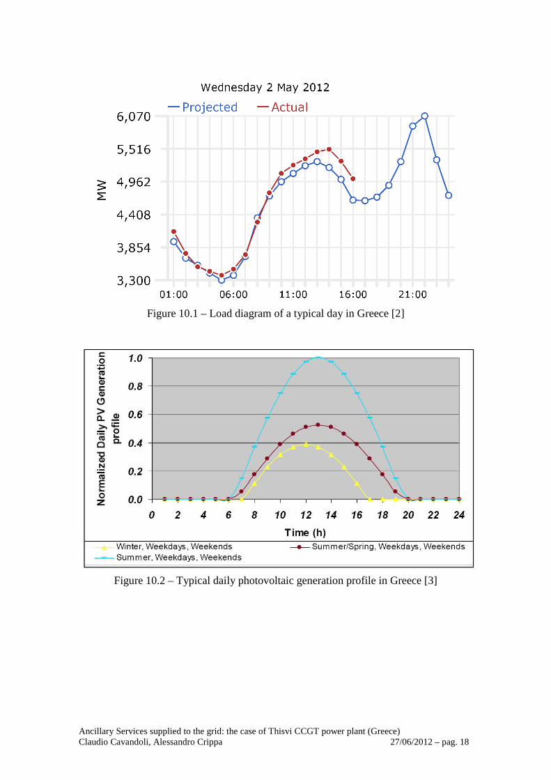
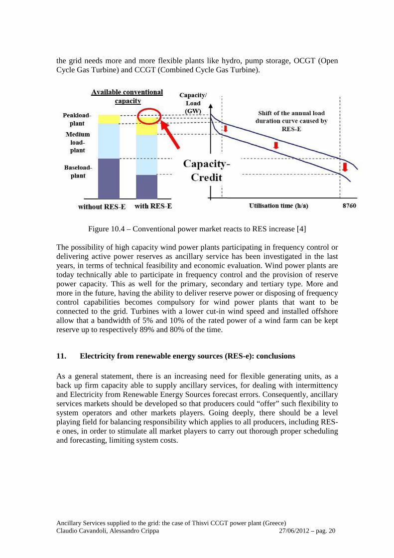
10. Electricity from renewable energy sources (RES-e): impact on transmission system operation When we speak about ancillary services to be supplied to the grid, we have to focus not only on Grid Code requirements, but also on Electricity from Renewable Energy Sources (RES-e) development impact on transmission and distribution systems operation. Greece has a photovoltaic and wind potential comparable to central – southern Italy. The development feasibility evaluation needs a detailed analysis on typical daily photovoltaic and wind generation expected profiles. Unpredictability can comply with the load diagram of a typical day. The lack of firmness of photovoltaic and wid generation (i.e. intermittency) and the lack of forecast precision (on day ahead and on day ongoing) play the most important role in the balancing energy of the system. As shown in Figure 10.1, Greek’s load diagram has deep fluctuations and two peaks. Photovoltaic generation profile (Figure 10.2 represents a typical shape) covers part of the first load peak around 13.00 – 14.00 h; however, the highest load peak is between 21.00 h and 22.00 h when photovoltaic production is certainly equal to zero. Wind generation profile is extremely variable (both in time and in magnitude) and unpredictable (see Figure 10.3). Therefore it is completely unmatched in comparison to load diagram.
Ancillary Services supplied to the grid: the case of Thisvi CCGT power plant (Greece) Claudio Cavandoli, Alessandro Crippa 27/06/2012 – pag. 18
Figure 10.1 – Load diagram of a typical day in Greece [2]
Figure 10.2 – Typical daily photovoltaic generation profile in Greece [3]

Ancillary Services supplied to the grid: the case of Thisvi CCGT power plant (Greece) Claudio Cavandoli, Alessandro Crippa 27/06/2012 – pag. 19
Figure 10.3 – Typical daily wind generation profile in Greece [3]
Variability and uncertainty, as well as difficult to forecast accurately, introduce power imbalances, lower levels of firm generation capacity and loss of services from displaced generation. The challenge is to maintain stable operation of an electrical grid with high penetration of Renewable Energy Sources. A possible solution to these problems could be the association of storage systems to renewable power plants. But at this stage of technology, storage systems are expensive and cannot represent a short-time solution within a global scenario of drastic government incentives cut, also considering that “green generators” are still struggling to reach the grid parity. Traditionally, the amount of balancing energy, or reserve, provided by thermal or hydro generation had to be sized to balance variations in demand or forced outages of the largest production units. Large penetration of intermittency and in particular wind and photovoltaic generation introduces additional requirements for balancing energy. The reasons are twofold. Firstly, since RES-e generation has limited predictability, in order to cope with the forecast error, larger amounts of flexible sources are necessary. Secondarily, also considering that the predictability of RES-e will improve in the future, even with perfect forecasting photovoltaic and wind generation will remain intermittent, non-controllable and very variable from one hour to another. Therefore, additional flexibility is required. Electricity systems with a high penetration of wind generation have a higher exposure to problems related to grid stability. The availability of an appropriate number of reserve power plants and their flexible dispatch becomes increasingly important to provide the necessary firmness and ancillary services to deal with. Every MW of wind capacity requires 1 MW of backup firm capacity, to ensure 90% availability. Figure 10.4 shows how the evolution in the composition of the optimal portfolio mix changes with increasing levels of RES-e. Going into details, some of the less flexible base-load conventional plants will be forced out of the markets, as well as peak load and medium load plants will cope with the variability of intermittent sources. Consequently,
Ancillary Services supplied to the grid: the case of Thisvi CCGT power plant (Greece) Claudio Cavandoli, Alessandro Crippa 27/06/2012 – pag. 20
the grid needs more and more flexible plants like hydro, pump storage, OCGT (Open Cycle Gas Turbine) and CCGT (Combined Cycle Gas Turbine).
Figure 10.4 – Conventional power market reacts to RES increase [4]
The possibility of high capacity wind power plants participating in frequency control or delivering active power reserves as ancillary service has been investigated in the last years, in terms of technical feasibility and economic evaluation. Wind power plants are today technically able to participate in frequency control and the provision of reserve power capacity. This as well for the primary, secondary and tertiary type. More and more in the future, having the ability to deliver reserve power or disposing of frequency control capabilities becomes compulsory for wind power plants that want to be connected to the grid. Turbines with a lower cut-in wind speed and installed offshore allow that a bandwidth of 5% and 10% of the rated power of a wind farm can be kept reserve up to respectively 89% and 80% of the time.
11. Electricity from renewable energy sources (RES-e): conclusions As a general statement, there is an increasing need for flexible generating units, as a back up firm capacity able to supply ancillary services, for dealing with intermittency and Electricity from Renewable Energy Sources forecast errors. Consequently, ancillary services markets should be developed so that producers could “offer” such flexibility to system operators and other markets players. Going deeply, there should be a level playing field for balancing responsibility which applies to all producers, including RES-e ones, in order to stimulate all market players to carry out thorough proper scheduling and forecasting, limiting system costs.

Ancillary Services supplied to the grid: the case of Thisvi CCGT power plant (Greece) Claudio Cavandoli, Alessandro Crippa 27/06/2012 – pag. 21
12. Acknowledgements The authors want to thank Ansaldo Energia and Politecnico di Milano / ACT Solutions for their active participation to the definition, implementation and testing of the Thisvi Power Plant frequency regulation control.
13. Bibliography [1] Grid Control and Power Exchange Code For Electricity [2] HTSO website: www.admie.gr [3] Development of future scenarios and EU network data collection, SIEMENS
WORKPAPER, 2008. [4] ENTSO-E website: www.entsoe.eu