Anchor Fastening Technology Manual 09 / 2012 - hilti.sk€¦ · Anchor Fastening Technology Manual...
70
10 / 2012 0 Anchor Fastening Technology Manual 09 / 2012
Transcript of Anchor Fastening Technology Manual 09 / 2012 - hilti.sk€¦ · Anchor Fastening Technology Manual...

10 / 20120
Anchor FasteningTechnology Manual
09 / 2012

Forword
10 / 2012 1
Foreword
Dear customer,
As it is our ambition to be the worldwide leader in fastening technology, we are continously striving to provide you with state-of-the-art technical information reflecting the latest developments in codes, regulations and approvals and technical information for our products.
The Fastening Technology Manuals for Post-installed Anchors and for Anchor Channel reflect our ongoing investment into long term research and development of leading fastening products.
This Fastening Technology Manual for Post-installed Anchors should be a valuable support tool for you when solving fastening tasks with Post-installed Anchor fastening technology. It should provide you with profound technical know-how, and help you to be more productive in your daily work without any compromise regarding reliability and safety.
As we strive to be a reliable partner for you, we would very much appreciate your feedback for improvements. We are available at any time to answer additional questions that even go beyond this content.
Raimund Zaggl
Business Unit Anchors

Important notices
10 / 20122
Important notices1. Construction materials and conditions vary on different sites. If it is suspected that the base
material has insufficient strength to achieve a suitable fastening, contact the Hilti Technical Advisory Service.
2. The information and recommendations given herein are based on the principles, formulae and safety factors set out in the Hilti technical instructions, the operating manuals, the setting instructions, the installation manuals and other data sheets that are believed to be correct at the time of writing. The data and values are based on the respective average values obtained from tests under laboratory or other controlled conditions. It is the users responsibility to use the data given in the light of conditions on site and taking into account the intended use of the products concerned. The user has to check the listed prerequisites and criteria conform with the conditions actually existing on the job-site. Whilst Hilti can give general guidance and advice, the nature of Hilti products means that the ultimate responsibility for selecting the right product for a particular application must lie with the customer.
3. All products must be used, handled and applied strictly in accordance with all current instructions for use published by Hilti, i.e. technical instructions, operating manuals, setting instructions, installation manuals and others.
4. All products are supplied and advice is given subject to the Hilti terms of business.
5. Hilti´s policy is one of continuous development. We therefore reserve the right to alter specifications, etc. without notice.
6. The given mean ultimate loads and characteristic data in the Anchor Fastening Technology Manual reflect actual test results and are thus valid only for the indicated test conditions. Due to variations in local base materials, on-site testing is required to determine performance at any specific site.
7. Hilti is not obligated for direct, indirect, incidental or consequential damages, losses or expenses in connection with, or by reason of, the use of, or inability to use the products for any purpose. Implied warranties of merchantability or fitness for a particular purpose are specifally excluded.
Hilti CorporationFL-9494 SchaanPrincipality of Liechtensteinwww.hilti.com
Hilti = registred trademark of the Hilti Corporation, Schaan

Contents
10 / 20124
Contents
Anchor technology and design ................................................................................................7
Anchor selector.....................................................................................................................................8
Legal environment ..............................................................................................................................20
Approvals ...........................................................................................................................................22
Base material .....................................................................................................................................28
Anchor design ....................................................................................................................................34
Design example..................................................................................................................................44
Corrosion............................................................................................................................................48
Dynamic loads (seismic, fatigue, shock) .............................................................................................52
Resistance to fire................................................................................................................................58
Mechanical anchoring systems ..............................................................................................71
HDA Design anchor............................................................................................................................72
HSL-3 carbon steel, heavy duty anchor ..............................................................................................88
HSL-GR stainless steel, heavy duty anchor......................................................................................100
HSC-A Safety anchor .......................................................................................................................110
HSC-I Safety anchor.........................................................................................................................120
HST Stud anchor ..............................................................................................................................130
HSA Stud anchor..............................................................................................................................140
HSV Stud anchor..............................................................................................................................160
HLC Sleeve anchor ..........................................................................................................................170
HAM Hard sleeve anchor..................................................................................................................176
HUS-HR Screw anchor, stainless steel.............................................................................................178
HUS Screw anchor, carbon steel ......................................................................................................194
HUS 6 Screw anchor, Redundant fastening......................................................................................210
HUS-A 6 / HUS-H 6 / HUS-I 6 / HUS-P 6 Screw anchor in precast prestressed hollow core slabs....218
HUS 6 / HUS-S 6 Screw anchor .......................................................................................................224
HKD Push-in anchor, Single anchor application................................................................................230
HKD Push-in anchor, Redundant fastening ......................................................................................244
HKV Push-in anchor, Single anchor application................................................................................252
HUD-1 Universal anchor...................................................................................................................256
HUD-L Universal anchor...................................................................................................................262
HLD Light duty anchor ......................................................................................................................266
HRD-U 10 / - S 10 / -U 14 Frame anchor ..........................................................................................270
HRD Frame anchor, Redundant fastening ........................................................................................276
HPS-1 Impact anchor .......................................................................................................................294
HHD-S Cavity anchor .......................................................................................................................298
HCA Coil anchor...............................................................................................................................300
HSP / HFP Drywall plug....................................................................................................................302
HA 8 Ring / hook anchor...................................................................................................................304
DBZ Wedge anchor ..........................................................................................................................308
HT Metal frame anchor .....................................................................................................................312
HK Ceiling anchor.............................................................................................................................316
HPD Aerated concrete anchor ..........................................................................................................322
HKH Hollow deck anchor..................................................................................................................328
HTB Hollow wall metal anchor ..........................................................................................................332
IDP Insulation fastener .....................................................................................................................336
IZ Insulation fastener ........................................................................................................................340
IDMS / IDMR Insulation fastener ......................................................................................................344
Contents
10 / 2012 5
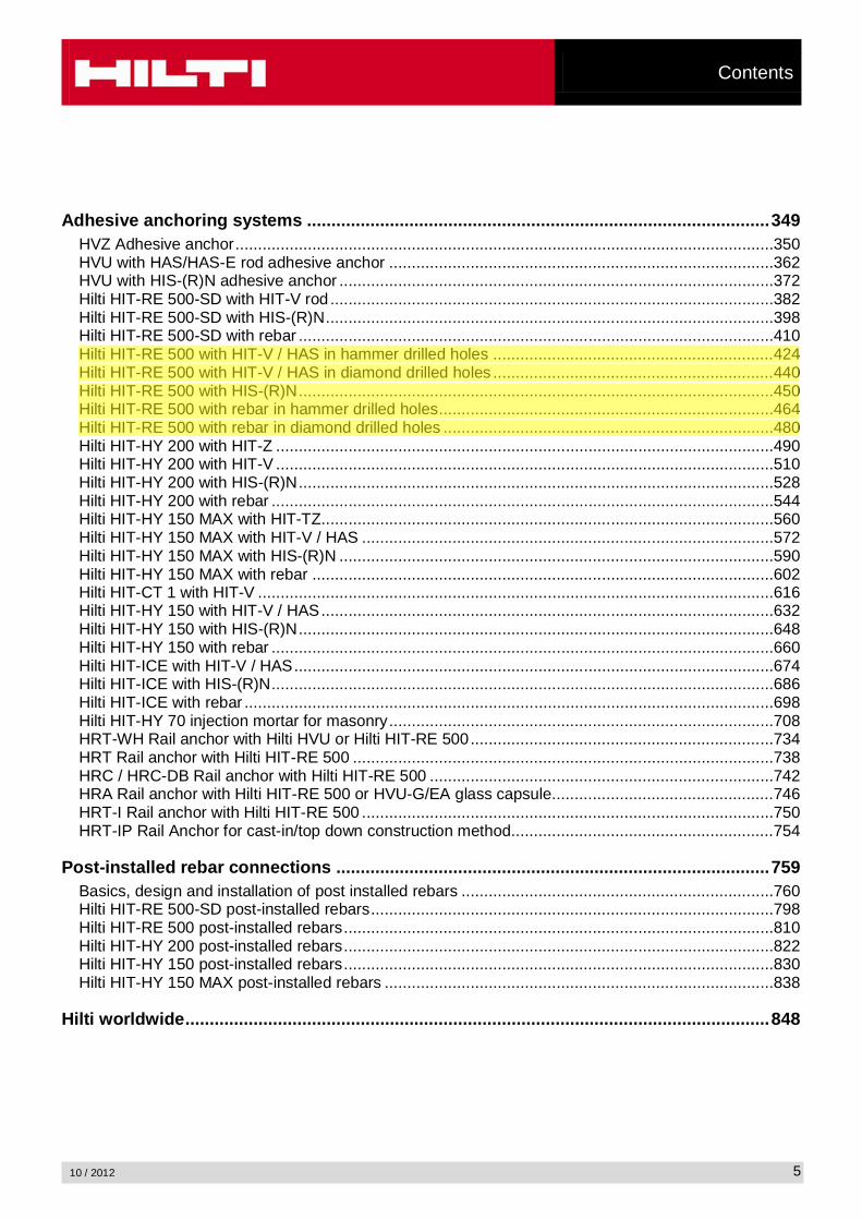
Adhesive anchoring systems ...............................................................................................349
HVZ Adhesive anchor.......................................................................................................................350
HVU with HAS/HAS-E rod adhesive anchor .....................................................................................362
HVU with HIS-(R)N adhesive anchor ................................................................................................372
Hilti HIT-RE 500-SD with HIT-V rod ..................................................................................................382
Hilti HIT-RE 500-SD with HIS-(R)N...................................................................................................398
Hilti HIT-RE 500-SD with rebar .........................................................................................................410
Hilti HIT-RE 500 with HIT-V / HAS in hammer drilled holes ..............................................................424
Hilti HIT-RE 500 with HIT-V / HAS in diamond drilled holes ..............................................................440
Hilti HIT-RE 500 with HIS-(R)N.........................................................................................................450
Hilti HIT-RE 500 with rebar in hammer drilled holes..........................................................................464
Hilti HIT-RE 500 with rebar in diamond drilled holes .........................................................................480
Hilti HIT-HY 200 with HIT-Z ..............................................................................................................490
Hilti HIT-HY 200 with HIT-V ..............................................................................................................510
Hilti HIT-HY 200 with HIS-(R)N.........................................................................................................528
Hilti HIT-HY 200 with rebar ...............................................................................................................544
Hilti HIT-HY 150 MAX with HIT-TZ....................................................................................................560
Hilti HIT-HY 150 MAX with HIT-V / HAS ...........................................................................................572
Hilti HIT-HY 150 MAX with HIS-(R)N ................................................................................................590
Hilti HIT-HY 150 MAX with rebar ......................................................................................................602
Hilti HIT-CT 1 with HIT-V ..................................................................................................................616
Hilti HIT-HY 150 with HIT-V / HAS....................................................................................................632
Hilti HIT-HY 150 with HIS-(R)N.........................................................................................................648
Hilti HIT-HY 150 with rebar ...............................................................................................................660
Hilti HIT-ICE with HIT-V / HAS..........................................................................................................674
Hilti HIT-ICE with HIS-(R)N...............................................................................................................686
Hilti HIT-ICE with rebar .....................................................................................................................698
Hilti HIT-HY 70 injection mortar for masonry.....................................................................................708
HRT-WH Rail anchor with Hilti HVU or Hilti HIT-RE 500...................................................................734
HRT Rail anchor with Hilti HIT-RE 500 .............................................................................................738
HRC / HRC-DB Rail anchor with Hilti HIT-RE 500 ............................................................................742
HRA Rail anchor with Hilti HIT-RE 500 or HVU-G/EA glass capsule.................................................746
HRT-I Rail anchor with Hilti HIT-RE 500 ...........................................................................................750
HRT-IP Rail Anchor for cast-in/top down construction method..........................................................754
Post-installed rebar connections .........................................................................................759
Basics, design and installation of post installed rebars .....................................................................760
Hilti HIT-RE 500-SD post-installed rebars.........................................................................................798
Hilti HIT-RE 500 post-installed rebars...............................................................................................810
Hilti HIT-HY 200 post-installed rebars...............................................................................................822
Hilti HIT-HY 150 post-installed rebars...............................................................................................830
Hilti HIT-HY 150 MAX post-installed rebars ......................................................................................838
Hilti worldwide........................................................................................................................848
KORECM
Highlight

Hilti HIT-RE 500with HIT-V / HASin hammer drilled holes
10 / 2012424
Hilti HIT-RE 500 with HIT-V / HASin hammer drilled holes
Injection mortar system Benefits
HiltiHIT-RE 500330 ml foil pack
(also available as 500 mland 1400 mlfoil pack)
- suitable for non-cracked concrete C 20/25 to C 50/60
- high loading capacity
- suitable for dry and water saturated concrete
- under water application
- large diameter applications
- high corrosion resistant
- long working time at elevatedtemperatures
- odourless epoxy
- embedment depth range:from 40 … 160 mm for M8to 120 … 600 mm for M30
Statik mixer
HAS rod
HAS-E rod
HIT-V rod
ConcreteSmall edge
distance and spacing
Variable embedment
depth
Fire resistance
Corrosion resistance
High corrosion resistance
European Technical Approval
CE conformity
PROFIS Anchor design
software
Approvals / certificatesDescription Authority / Laboratory No. / date of issueEuropean technical approval a) DIBt, Berlin ETA-04/0027 / 2009-05-20
Fire test report IBMB, BraunschweigUB 3565 / 4595 / 2006-10-29UB 3588 / 4825 / 2005-11-15
Assessment report (fire) warringtonfireWF 166402 / 2007-10-26 & suppl. WF 172920 / 2008-05-27
a) All data given in this section according ETA-04/0027, issue 2009-05-20.

Hilti HIT-RE 500with HIT-V / HAS
in hammer drilled holes
10 / 2012 425
Basic loading data (for a single anchor)All data in this section applies to For details see Simplified design method- Correct setting (See setting instruction)- No edge distance and spacing influence- Steel failure- Base material thickness, as specified in the table- One typical embedment depth, as specified in the table- One anchor material, as specified in the tables- Concrete C 20/25, fck,cube = 25 N/mm²- Temperature range I
(min. base material temperature -40°C, max. long term/short term base material temperature: +24°C/40°C)- Installation temperature range +5°C to +40°C
Embedment depth a) and base material thickness for the basic loading data.Mean ultimate resistance, characteristic resistance, design resistance, recommended loads.Anchor size M8 M10 M12 M16 M20 M24 M27 M30 M33 M36 M39Typical embedment depth [mm] 80 90 110 125 170 210 240 270 300 330 360Base material thickness [mm] 110 120 140 165 220 270 300 340 380 410 450
a) The allowed range of embedment depth is shown in the setting details. The corresponding load values can be calculated according to the simplified design method.
Mean ultimate resistance: concrete C 20/25 – fck,cube = 25 N/mm², anchor HIT-V 5.8
Data according ETA-04/0027, issue 2008-11-03 Additional Hilti technical data
Anchor size M8 M10 M12 M16 M20 M24 M27 M30 M33 M36 M39
Tensile NRu,m HIT-V 5.8 [kN] 18,9 30,5 44,1 83,0 129,2 185,9 241,5 295,1 364,4 428,9 459,9
Shear VRu,m HIT-V 5.8 [kN] 9,5 15,8 22,1 41,0 64,1 92,4 120,8 147,0 182,2 214,5 256,2
Characteristic resistance: concrete C 20/25 – fck,cube = 25 N/mm², anchor HIT-V 5.8
Data according ETA-04/0027, issue 2008-11-03 Additional Hilti technical data
Anchor size M8 M10 M12 M16 M20 M24 M27 M30 M33 M36 M39
Tensile NRk HIT-V 5.8 [kN] 18,0 29,0 42,0 70,6 111,9 153,7 187,8 224,0 262,4 302,7 344,9
Shear VRk HIT-V 5.8 [kN] 9,0 15,0 21,0 39,0 61,0 88,0 115,0 140,0 173,5 204,3 244,0
Design resistance: concrete C 20/25 – fck,cube = 25 N/mm², anchor HIT-V 5.8
Data according ETA-04/0027, issue 2008-11-03 Additional Hilti technical data
Anchor size M8 M10 M12 M16 M20 M24 M27 M30 M33 M36 M39
Tensile NRd HIT-V 5.8 [kN] 12,0 19,3 27,7 33,6 53,3 73,2 89,4 106,7 125,0 144,2 164,3
Shear VRd HIT-V 5.8 [kN] 7,2 12,0 16,8 31,2 48,8 70,4 92,0 112,0 138,8 163,4 195,2
Recommended loads a): concrete C 20/25 – fck,cube = 25 N/mm², anchor HIT-V 5.8
Data according ETA-04/0027, issue 2008-11-03 Additional Hilti technical data
Anchor size M8 M10 M12 M16 M20 M24 M27 M30 M33 M36 M39
Tensile Nrec HIT-V 5.8 [kN] 8,6 13,8 19,8 24,0 38,1 52,3 63,9 76,2 89,3 103,0 117,3
Shear Vrec HIT-V 5.8 [kN] 5,1 8,6 12,0 22,3 34,9 50,3 65,7 80,0 99,1 116,7 139,4
a) With overall partial safety factor for action = 1,4. The partial safety factors for action depend on the type of loading and shall be taken from national regulations.

Hilti HIT-RE 500with HIT-V / HASin hammer drilled holes
10 / 2012426
Service temperature rangeHilti HIT-RE 500 injection mortar may be applied in the temperature ranges given below. An elevated base material temperature may lead to a reduction of the design bond resistance.
Temperature range Base material temperature
Maximum long term base material temperature
Maximum short term base material temperature
Temperature range I -40 °C to +40 °C +24 °C +40 °CTemperature range II -40 °C to +58 °C +35 °C +58 °CTemperature range III -40 °C to +70 °C +43 °C +70 °C
Max short term base material temperatureShort-term elevated base material temperatures are those that occur over brief intervals, e.g. as a result of diurnal cycling.
Max long term base material temperatureLong-term elevated base material temperatures are roughly constant over significant periods of time.
Materials
Mechanical properties of HIT-V / HAS
Data according ETA-04/0027, issue 2008-11-03 Additional Hilti technical data
Anchor size M8 M10 M12 M16 M20 M24 M27 M30 M33 M36 M39
Nominal tensile strength fuk
HIT-V/HAS 5.8 [N/mm²] 500 500 500 500 500 500 500 500 500 500 500HIT-V/HAS 8.8 [N/mm²] 800 800 800 800 800 800 800 800 800 800 800HIT-V/HAS -R [N/mm²] 700 700 700 700 700 700 500 500 500 500 500HIT-V/HAS -HCR [N/mm²] 800 800 800 800 800 700 700 700 500 500 500
Yield strength fyk
HIT-V/HAS 5.8 [N/mm²] 400 400 400 400 400 400 400 400 400 400 400HIT-V/HAS 8.8 [N/mm²] 640 640 640 640 640 640 640 640 640 640 640HIT-V/HAS -R [N/mm²] 450 450 450 450 450 450 210 210 210 210 210HIT-V/HAS -HCR [N/mm²] 600 600 600 600 600 400 400 400 250 250 250
Stressed cross-section As
HAS [mm²] 32,8 52,3 76,2 144 225 324 427 519 647 759 913
HIT-V [mm²] 36,6 58,0 84,3 157 245 353 459 561 694 817 976
Moment of resistance W
HAS [mm³] 27,0 54,1 93,8 244 474 809 1274 1706 2321 2949 3891
HIT-V [mm³] 31,2 62,3 109 277 541 935 1387 1874 2579 3294 4301

Hilti HIT-RE 500with HIT-V / HAS
in hammer drilled holes
10 / 2012 427
Material qualityPart MaterialThreaded rodHIT-V(F),HAS 5.8 M8 – M24
Strength class 5.8, A5 > 8% ductile
Threaded rodHIT-V(F),HAS 8.8 M27 – M39
Strength class 8.8, A5 > 8% ductile
Threaded rodHIT-V-R, HAS-R
Stainless steel grade A4, A5 > 8% ductile
1.4578; 1.4571; 1.4439; 1.4362
Threaded rodHIT-V-HCR, HAS-HCR
High corrosion resistant steel, 1.4529; 1.4565m = 800 N/mm², Rp 0.2 = 640 N/mm², A5 > 8% ductile
M24 to M30: Rm = 700 N/mm², Rp 0.2 = 400 N/mm², A5 > 8% ductile
WasherISO 7089
Steel galvanized, hot dipped galvanizedStainless steel, 1.4401; 1.4404; 1.4578; 1.4571; 1.4439; 1.4362High corrosion resistant steel, 1.4529; 1.4565
NutEN ISO 4032
Strength class 8,
Strength class 70, stainless steel grade A4,1.4401; 1.4404; 1.4578; 1.4571; 1.4439; 1.4362Strength class 70, high corrosion resistant steel,1.4529; 1.4565
Anchor dimensions
Anchor size M8 M10 M12 M16 M20 M24 M27 M30 M33 M36 M39
Anchor rodHAS, HAS-E,HAS-R, HAS-ERHAS-HCR
M8x
80
M10
x90
M12
x11
0
M16
x12
5
M20
x17
0
M24
x21
0
M27
x24
0
M30
x27
0
M33
x30
0
M36
x33
0
M39
x36
0Anchor embedment depth [mm] 80 90 110 125 170 210 240 270 300 330 360
Anchor rodHIT-V, HIT-V-R, HIT-V-HCR
Anchor rods HIT-V (-R / -HCR) are available in variable length
Setting
installation equipmentAnchor size M8 M10 M12 M16 M20 M24 M27 M30Rotary hammer TE2 – TE16 TE40 – TE70Other tools compressed air gun or blow out pump, set of cleaning brushes, dispenserAdditionalHilti recommended tools DD EC-1, DD 100 … DD xxx a)
a) For anchors in diamond drilled holes load values for combined pull-out and concrete cone resistance have to be reduced (see section “Setting instruction”)

Hilti HIT-RE 500with HIT-V / HASin hammer drilled holes
10 / 2012428
Setting instruction
Dry and water-saturated concrete, hammer drilling
a)
Brush bore hole with required steel brush HIT-RBa) Note: Manual cleaning only for hef 250 mm and anchor size M16For detailed information on installation see instruction for use given with the package of the product.

Hilti HIT-RE 500with HIT-V / HAS
in hammer drilled holes
10 / 2012 429
Water filled bore hole or submerged, hammer drilling
Brush bore hole with required steel brush HIT-RBFor detailed information on installation see instruction for use given with the package of the product.

Hilti HIT-RE 500with HIT-V / HASin hammer drilled holes
10 / 2012430
Curing time for general conditionsData according ETA-04/0027, issue 2009-05-20
Temperatureof the base material
Working time in which anchorcan be inserted and adjusted tgel
Curing time before anchorcan be fully loaded tcure
40 °C 12 min 4 h30 °C to 39 °C 12 min 8 h20 °C to 29 °C 20 min 12 h15 °C to 19 °C 30 min 24 h10 °C to 14 °C 90 min 48 h
5 °C to 9 °C 120 min 72 h
For dry concrete curing times may be reduced according to the following table.For installation temperatures below +5 °C all load values have to be reduced according to the load reduction factors given below.
Curing time for dry concreteAdditional Hilti technical data
Temperatureof the
base material
Reduced curing time before anchor can be
fully loaded tcure,dry
Working time in which anchor can be inserted
and adjusted tgel
Load reduction factor
40 °C 4 h 12 min 130 °C 8 h 12 min 120 °C 12 h 20 min 115 °C 18 h 30 min 110 °C 24 h 90 min 15 °C 36 h 120 min 10 °C 50 h 3 h 0,7-5 °C 72 h 4 h 0,6

Hilti HIT-RE 500with HIT-V / HAS
in hammer drilled holes
10 / 2012 431
Setting details
Data according ETA-04/0027, issue 2009-05-20 Additional Hilti technical data
Anchor size M8 M10 M12 M16 M20 M24 M27 M30 M33 M36 M39Nominal diameter of drill bit
d0 [mm] 10 12 14 18 24 28 30 35 37 40 42
Effective anchorage and drill hole depth range a)
hef,min [mm] 40 40 48 64 80 96 108 120 132 144 156
hef,max [mm] 160 200 240 320 400 480 540 600 660 720 780
Minimum base material thickness
hmin [mm]hef + 30 mm
hef + 2 d0
Diameter of clearance hole in the fixture
df [mm] 9 12 14 18 22 26 30 33 36 39 42
Minimum spacing smin [mm] 40 50 60 80 100 120 135 150 165 180 195Minimum edge distance
cmin [mm] 40 50 60 80 100 120 135 150 165 180 195
Critical spacing for splitting failure
scr,sp 2 ccr,sp
Critical edge distance for splitting failure b) ccr,sp [mm]
1,0 hef for h / hef
4,6 hef - 1,8 h for 2,0 > h / hef > 1,3
2,26 hef for h / hef 1,3
Critical spacing for concrete cone failure
scr,N 2 ccr,N
Critical edge distance for concrete cone failure c)
ccr,N 1,5 hef
Torque moment d) Tmax [Nm] 10 20 40 80 150 200 270 300 330 360 390
For spacing (edge distance) smaller than critical spacing (critical edge distance) the design loads have to be reduced.
a) hef,min hef ef,max (hef: embedment depth)
b) h: base material thickness (h hmin)
c) The critical edge distance for concrete cone failure depends on the embedment depth hef and the design bond resistance. The simplified formula given in this table is on the save side.
d) This is the maximum recommended torque moment to avoid splitting failure during installation for anchors with minimum spacing and/or edge distance.
Hilti HIT-RE 500with HIT-V / HASin hammer drilled holes
10 / 2012432
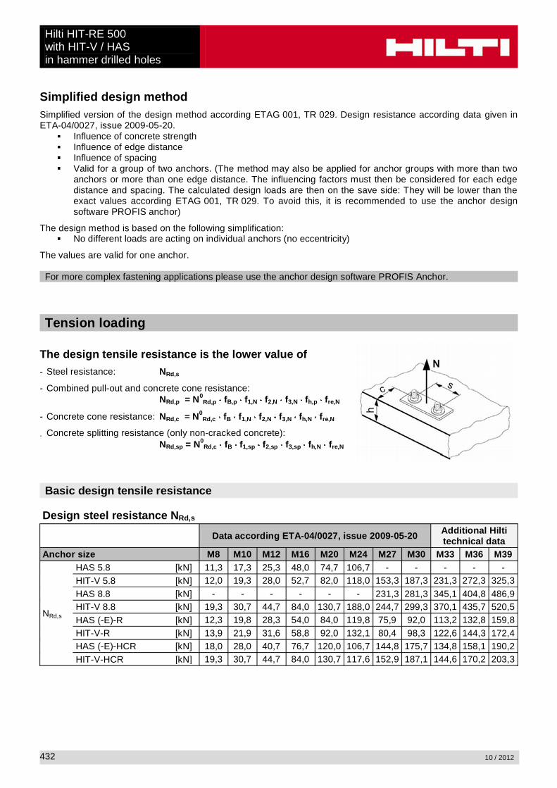
Simplified design methodSimplified version of the design method according ETAG 001, TR 029. Design resistance according data given in ETA-04/0027, issue 2009-05-20.
Influence of concrete strengthInfluence of edge distanceInfluence of spacingValid for a group of two anchors. (The method may also be applied for anchor groups with more than twoanchors or more than one edge distance. The influencing factors must then be considered for each edge distance and spacing. The calculated design loads are then on the save side: They will be lower than the exact values according ETAG 001, TR 029. To avoid this, it is recommended to use the anchor design software PROFIS anchor)
The design method is based on the following simplification:No different loads are acting on individual anchors (no eccentricity)
The values are valid for one anchor.
For more complex fastening applications please use the anchor design software PROFIS Anchor.
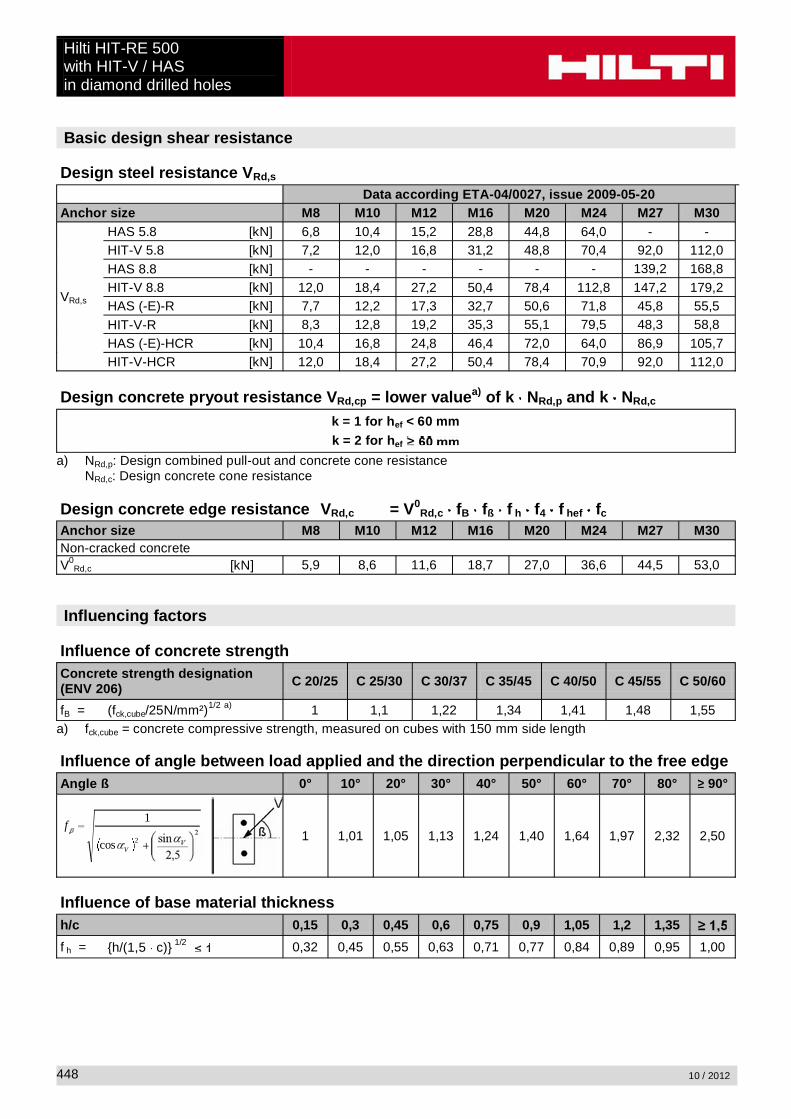
Tension loading
The design tensile resistance is the lower value of- Steel resistance: NRd,s
- Combined pull-out and concrete cone resistance:NRd,p = N0
Rd,p fB,p f1,N f2,N f3,N fh,p fre,N
- Concrete cone resistance: NRd,c = N0Rd,c fB f1,N f2,N f3,N fh,N fre,N
- Concrete splitting resistance (only non-cracked concrete):NRd,sp = N0
Rd,c fB f1,sp f2,sp f3,sp fh,N fre,N
Basic design tensile resistance
Design steel resistance NRd,s
Data according ETA-04/0027, issue 2009-05-20 Additional Hilti technical data
Anchor size M8 M10 M12 M16 M20 M24 M27 M30 M33 M36 M39
NRd,s
HAS 5.8 [kN] 11,3 17,3 25,3 48,0 74,7 106,7 - - - - -HIT-V 5.8 [kN] 12,0 19,3 28,0 52,7 82,0 118,0 153,3 187,3 231,3 272,3 325,3HAS 8.8 [kN] - - - - - - 231,3 281,3 345,1 404,8 486,9HIT-V 8.8 [kN] 19,3 30,7 44,7 84,0 130,7 188,0 244,7 299,3 370,1 435,7 520,5HAS (-E)-R [kN] 12,3 19,8 28,3 54,0 84,0 119,8 75,9 92,0 113,2 132,8 159,8HIT-V-R [kN] 13,9 21,9 31,6 58,8 92,0 132,1 80,4 98,3 122,6 144,3 172,4HAS (-E)-HCR [kN] 18,0 28,0 40,7 76,7 120,0 106,7 144,8 175,7 134,8 158,1 190,2HIT-V-HCR [kN] 19,3 30,7 44,7 84,0 130,7 117,6 152,9 187,1 144,6 170,2 203,3

Hilti HIT-RE 500with HIT-V / HAS
in hammer drilled holes
10 / 2012 433
Design combined pull-out and concrete cone resistance for anchors in diamond drilled holes a)
NRd,p = N0Rd,p fB,p f1,N f2,N f3,N fh,p fre,N
Data according ETA-04/0027, issue 2009-05-20 Additional Hilti technical data
Anchor size M8 M10 M12 M16 M20 M24 M27 M30 M33 M36 M39Typical embedment depthhef,typ [mm] 80 90 110 125 170 210 240 270 300 330 360
N0Rd,p Temperature range I [kN] 15,3 21,5 31,6 44,9 76,3 105,6 135,7 157,5 171,0 203,3 232,9
N0Rd,p Temperature range II [kN] 12,4 17,5 25,7 35,9 61,0 82,9 106,6 133,3 136,8 162,6 186,3
N0Rd,p Temperature range III [kN] 7,7 10,8 15,8 22,4 35,6 52,8 63,0 78,8 82,1 97,6 111,8
a) Additional Hilti technical data (not part of ETA-04/0027, issue 2009-05-20):The design values for combined pull-out and concrete cone resistance may be increased by 20 % for anchor installation in dry concrete (concrete not in contact with water before/during installation and curing).
Design concrete cone resistance a) NRd,c = N0Rd,c fB f1,N f2,N f3,N fh,N fre,N
Design splitting resistance NRd,spa) = N0
Rd,c fB f1,sp f2,sp f3,sp f h,N fre,N
Data according ETA-04/0027, issue 2009-05-20 Additional Hilti technical data
Anchor size M8 M10 M12 M16 M20 M24 M27 M30 M33 M36 M39N0
Rd,c [kN] 17,2 20,5 27,7 33,6 53,3 73,2 89,4 106,7 125,0 144,2 164,3a) Additional Hilti technical data (not part of ETA-04/0027, issue 2009-05-20):
The design values for concrete cone and splitting resistance may be increased by 20 % for anchor installationin dry concrete (concrete not in contact with water before/during installation and curing).
Influencing factors
Influence of concrete strength on combined pull-out and concrete cone resistanceConcrete strength designation(ENV 206) C 20/25 C 25/30 C 30/37 C 35/45 C 40/50 C 45/55 C 50/60
fB,p = (fck,cube/25N/mm²)0,1 a) 1 1,02 1,04 1,06 1,07 1,08 1,09a) fck,cube = concrete compressive strength, measured on cubes with 150 mm side length
Influence of embedment depth on combined pull-out and concrete cone resistancefh,p = hef/hef,typ
Influence of concrete strength on concrete cone resistanceConcrete strength designation(ENV 206) C 20/25 C 25/30 C 30/37 C 35/45 C 40/50 C 45/55 C 50/60
fB = (fck,cube/25N/mm²)1/2 a) 1 1,1 1,22 1,34 1,41 1,48 1,55a) fck,cube = concrete compressive strength, measured on cubes with 150 mm side length

Hilti HIT-RE 500with HIT-V / HASin hammer drilled holes
10 / 2012434
Influence of edge distance a)
c/ccr,N0,1 0,2 0,3 0,4 0,5 0,6 0,7 0,8 0,9 1
c/ccr,sp
f1,N = 0,7 + 0,3 c/ccr,N0,73 0,76 0,79 0,82 0,85 0,88 0,91 0,94 0,97 1
f1,sp = 0,7 + 0,3 c/ccr,sp
f2,N = 0,5 (1 + c/ccr,N)0,55 0,60 0,65 0,70 0,75 0,80 0,85 0,90 0,95 1
f2,sp = 0,5 (1 + c/ccr,sp)a) The the edge distance shall not be smaller than the minimum edge distance cmin given in the table with the
setting details. These influencing factors must be considered for every edge distance smaller than the critical edge distance.
Influence of anchor spacing a)
s/scr,N0,1 0,2 0,3 0,4 0,5 0,6 0,7 0,8 0,9 1
s/scr,sp
f3,N = 0,5 (1 + s/scr,N)0,55 0,60 0,65 0,70 0,75 0,80 0,85 0,90 0,95 1
f3,sp = 0,5 (1 + s/scr,sp)a) The anchor spacing shall not be smaller than the minimum anchor spacing smin given in the table with the
setting details. This influencing factor must be considered for every anchor spacing.
Influence of embedment depth on concrete cone resistancefh,N = (hef/hef,typ)
1,5
Influence of reinforcementhef [mm] 40 50 60 70 80 90
fre,N = 0,5 + hef 0,7 a) 0,75 a) 0,8 a) 0,85 a) 0,9 a) 0,95 a) 1a) This factor applies only for dense reinforcement. If in the area of anchorage there is reinforcement with a
spacing mm, then a factor fre = 1may be applied.
Shear loading
The design shear resistance is the lower value of
- Steel resistance: VRd,s
- Concrete pryout resistance: VRd,cp = k lower value of NRd,p and NRd,c
- Concrete edge resistance: VRd,c = V0Rd,c fB fß f h f4 f hef fc

Hilti HIT-RE 500with HIT-V / HAS
in hammer drilled holes
10 / 2012 435
Basic design shear resistance
Design steel resistance VRd,s
Data according ETA-04/0027, issue 2009-05-20 Additional Hilti technical data
Anchor size M8 M10 M12 M16 M20 M24 M27 M30 M33 M36 M39
VRd,s
HAS 5.8 [kN] 6,8 10,4 15,2 28,8 44,8 64,0 - - - - -HIT-V 5.8 [kN] 7,2 12,0 16,8 31,2 48,8 70,4 92,0 112,0 138,8 163,4 195,2HAS 8.8 [kN] - - - - - - 139,2 168,8 207,0 242,9 292,2HIT-V 8.8 [kN] 12,0 18,4 27,2 50,4 78,4 112,8 147,2 179,2 222,1 261,4 312,3HAS (-E)-R [kN] 7,7 12,2 17,3 32,7 50,6 71,8 45,8 55,5 67,9 79,7 95,9HIT-V-R [kN] 8,3 12,8 19,2 35,3 55,1 79,5 48,3 58,8 72,9 85,8 102,5HAS (-E)-HCR [kN] 10,4 16,8 24,8 46,4 72,0 64,0 86,9 105,7 80,9 94,9 114,1HIT-V-HCR [kN] 12,0 18,4 27,2 50,4 78,4 70,9 92,0 112,0 86,8 102,1 122,0
Design concrete pryout resistance VRd,cp = lower valuea) of k NRd,p and k NRd,c
k = 1 for hef < 60 mmk = 2 for hef
a) NRd,p: Design combined pull-out and concrete cone resistanceNRd,c: Design concrete cone resistance
Design concrete edge resistance VRd,c = V0Rd,c fB fß f h f4 f hef fc
Anchor size M8 M10 M12 M16 M20 M24 M27 M30 M33 M36 M39Non-cracked concreteV0
Rd,c [kN] 5,9 8,6 11,6 18,7 27,0 36,6 44,5 53,0 62,1 71,7 81,9
Influencing factors
Influence of concrete strengthConcrete strength designation(ENV 206) C 20/25 C 25/30 C 30/37 C 35/45 C 40/50 C 45/55 C 50/60
fB = (fck,cube/25N/mm²)1/2 a) 1 1,1 1,22 1,34 1,41 1,48 1,55a) fck,cube = concrete compressive strength, measured on cubes with 150 mm side length
Influence of angle between load applied and the direction perpendicular to the free edgeAngle ß 0° 10° 20° 30° 40° 50° 60° 70° 80° 90°
1f
1 1,01 1,05 1,13 1,24 1,40 1,64 1,97 2,32 2,50
Influence of base material thicknessh/c 0,15 0,3 0,45 0,6 0,75 0,9 1,05 1,2 1,35
f h = {h/(1,5 c)} 1/2 0,32 0,45 0,55 0,63 0,71 0,77 0,84 0,89 0,95 1,00

Hilti HIT-RE 500with HIT-V / HASin hammer drilled holes
10 / 2012436
Influence of anchor spacing and edge distance a) for concrete edge resistance: f4
f4 = (c/hef)1,5 (1 + s / [3 c]) 0,5
c/hefSingle anchor
Group of two anchors s/hef
0,75 1,50 2,25 3,00 3,75 4,50 5,25 6,00 6,75 7,50 8,25 9,00 9,75 ����� �����0,50 0,35 0,27 0,35 0,35 0,35 0,35 0,35 0,35 0,35 0,35 0,35 0,35 0,35 0,35 0,35 0,350,75 0,65 0,43 0,54 0,65 0,65 0,65 0,65 0,65 0,65 0,65 0,65 0,65 0,65 0,65 0,65 0,651,00 1,00 0,63 0,75 0,88 1,00 1,00 1,00 1,00 1,00 1,00 1,00 1,00 1,00 1,00 1,00 1,001,25 1,40 0,84 0,98 1,12 1,26 1,40 1,40 1,40 1,40 1,40 1,40 1,40 1,40 1,40 1,40 1,401,50 1,84 1,07 1,22 1,38 1,53 1,68 1,84 1,84 1,84 1,84 1,84 1,84 1,84 1,84 1,84 1,841,75 2,32 1,32 1,49 1,65 1,82 1,98 2,15 2,32 2,32 2,32 2,32 2,32 2,32 2,32 2,32 2,322,00 2,83 1,59 1,77 1,94 2,12 2,30 2,47 2,65 2,83 2,83 2,83 2,83 2,83 2,83 2,83 2,832,25 3,38 1,88 2,06 2,25 2,44 2,63 2,81 3,00 3,19 3,38 3,38 3,38 3,38 3,38 3,38 3,382,50 3,95 2,17 2,37 2,57 2,77 2,96 3,16 3,36 3,56 3,76 3,95 3,95 3,95 3,95 3,95 3,952,75 4,56 2,49 2,69 2,90 3,11 3,32 3,52 3,73 3,94 4,15 4,35 4,56 4,56 4,56 4,56 4,563,00 5,20 2,81 3,03 3,25 3,46 3,68 3,90 4,11 4,33 4,55 4,76 4,98 5,20 5,20 5,20 5,203,25 5,86 3,15 3,38 3,61 3,83 4,06 4,28 4,51 4,73 4,96 5,18 5,41 5,63 5,86 5,86 5,863,50 6,55 3,51 3,74 3,98 4,21 4,44 4,68 4,91 5,14 5,38 5,61 5,85 6,08 6,31 6,55 6,553,75 7,26 3,87 4,12 4,36 4,60 4,84 5,08 5,33 5,57 5,81 6,05 6,29 6,54 6,78 7,02 7,264,00 8,00 4,25 4,50 4,75 5,00 5,25 5,50 5,75 6,00 6,25 6,50 6,75 7,00 7,25 7,50 7,754,25 8,76 4,64 4,90 5,15 5,41 5,67 5,93 6,18 6,44 6,70 6,96 7,22 7,47 7,73 7,99 8,254,50 9,55 5,04 5,30 5,57 5,83 6,10 6,36 6,63 6,89 7,16 7,42 7,69 7,95 8,22 8,49 8,754,75 10,35 5,45 5,72 5,99 6,27 6,54 6,81 7,08 7,36 7,63 7,90 8,17 8,45 8,72 8,99 9,265,00 11,18 5,87 6,15 6,43 6,71 6,99 7,27 7,55 7,83 8,11 8,39 8,66 8,94 9,22 9,50 9,785,25 12,03 6,30 6,59 6,87 7,16 7,45 7,73 8,02 8,31 8,59 8,88 9,17 9,45 9,74 10,02 10,315,50 12,90 6,74 7,04 7,33 7,62 7,92 8,21 8,50 8,79 9,09 9,38 9,67 9,97 10,26 10,55 10,85
a) The anchor spacing and the edge distance shall not be smaller than the minimum anchor spacing smin and the minimum edge distance cmin.
Influence of embedment depthhef/d 4 4,5 5 6 7 8 9 10 11
f hef = 0,05 (hef / d)1,68 0,51 0,63 0,75 1,01 1,31 1,64 2,00 2,39 2,81
hef/d 12 13 14 15 16 17 18 19 20
f hef = 0,05 (hef / d)1,68 3,25 3,72 4,21 4,73 5,27 5,84 6,42 7,04 7,67
Influence of edge distance a)
c/d 4 6 8 10 15 20 30 40
fc = (d / c)0,19 0,77 0,71 0,67 0,65 0,60 0,57 0,52 0,50a) The edge distance shall not be smaller than the minimum edge distance cmin.
Combined tension and shear loading
For combined tension and shear loading see section “Anchor Design”.
Precalculated valuesRecommended loads can be calculated by dividing the design resistance by an overall partial safety factor for action = 1,4. The partial safety factors for action depend on the type of loading and shall be taken from national regulations.

Hilti HIT-RE 500with HIT-V / HAS
in hammer drilled holes
10 / 2012 437
Design resistance: concrete C 20/25 – fck,cube = 25 N/mm², Temperature range I
Data according ETA-04/0027, issue 2009-05-20 Additional Hilti technical data
Anchor size M8 M10 M12 M16 M20 M24 M27 M30 M33 M36 M39Embedment depth hef,1 = [mm] 48 60 72 96 120 144 162 180 198 216 234Base material thickness hmin= [mm] 100 100 102 132 168 200 222 250 272 296 324
Tensile NRd: single anchor, no edge effectsHIT-V 5.8HIT-V 8.8HIT-V-RHIT-V-HCR
[kN] 8,0 11,2 14,7 22,6 31,6 41,6 49,6 58,1 67,0 76,3 86,1
Shear VRd: single anchor, no edge effects, without lever armHIT-V 5.8 [kN] 7,2 12,0 16,8 31,2 48,8 70,4 92,0 112,0 138,8 163,4 195,2HIT-V 8.8 [kN] 11,2 18,4 27,2 50,4 78,4 112,8 138,8 162,6 187,6 213,8 241,0HIT-V-R [kN] 8,3 12,8 19,2 35,3 55,1 79,5 48,3 58,8 72,9 85,8 102,5HIT-V-HCR [kN] 11,2 18,4 27,2 50,4 78,4 70,9 92,0 112,0 86,8 102,1 122,0
Design resistance: concrete C 20/25 – fck,cube = 25 N/mm², Temperature range I
Data according ETA-04/0027, issue 2009-05-20 Additional Hilti technical data
Anchor size M8 M10 M12 M16 M20 M24 M27 M30 M33 M36 M39Embedment depth hef,1 = [mm] 48 60 72 96 120 144 162 180 198 216 234Base material thickness hmin= [mm] 100 100 102 132 168 200 222 250 272 296 324Edge distance c = cmin= [mm] 40 50 60 80 100 120 135 150 165 180 195
Tensile NRd: single anchor, min. edge distance (c = cmin)HIT-V 5.8HIT-V 8.8HIT-V-RHIT-V-HCR
[kN] 5,4 7,3 8,5 12,9 18,2 23,8 28,2 33,2 38,1 43,4 49,2
Shear VRd: single anchor, min. edge distance (c = cmin) , without lever armHIT-V 5.8HIT-V 8.8HIT-V-RHIT-V-HCR
[kN] 3,4 4,9 6,7 10,8 15,7 21,4 26,0 31,1 36,5 42,2 48,3
Design resistance: concrete C 20/25 – fck,cube = 25 N/mm², Temperature range I(load values are valid for single anchor)
Data according ETA-04/0027, issue 2009-05-20 Additional Hilti technical data
Anchor size M8 M10 M12 M16 M20 M24 M27 M30 M33 M36 M39Embedment depth hef,1 = [mm] 48 60 72 96 120 144 162 180 198 216 234Base material thickness hmin= [mm] 100 100 102 132 168 200 222 250 272 296 324Spacing s = smin= [mm] 40 50 60 80 100 120 135 150 165 180 195
Tensile NRd: double anchor, no edge effects, min. spacing (s = smin)HIT-V 5.8HIT-V 8.8HIT-V-RHIT-V-HCR
[kN] 5,1 7,0 8,8 13,5 19,0 24,9 29,6 34,8 40,1 45,6 51,5
Shear VRd: double anchor, no edge effects, min. spacing (s = smin) , without lever armHIT-V 5.8 [kN] 7,2 12,0 16,8 31,2 48,8 70,4 88,7 103,9 119,9 136,6 154,0HIT-V 8.8 [kN] 7,2 18,4 26,3 40,5 56,5 74,3 88,7 103,9 119,9 136,6 154,0HIT-V-R [kN] 7,2 12,8 19,2 35,3 55,1 74,3 48,3 58,8 72,9 85,8 102,5HIT-V-HCR [kN] 7,2 18,4 26,3 40,5 56,5 70,9 88,7 103,9 86,8 102,1 122,0

Hilti HIT-RE 500with HIT-V / HASin hammer drilled holes
10 / 2012438
Design resistance: concrete C 20/25 – fck,cube = 25 N/mm², Temperature range I
Data according ETA-04/0027, issue 2009-05-20 Additional Hilti technical data
Anchor size M8 M10 M12 M16 M20 M24 M27 M30 M33 M36 M39Embedment depth hef,typ = [mm] 80 90 110 125 170 210 240 270 300 330 360Base material thickness hmin= [mm] 110 120 140 161 218 266 300 340 374 410 450
Tensile NRd: single anchor, no edge effectsHIT-V 5.8 [kN] 12,0 19,3 27,7 33,6 53,3 73,2 89,4 106,7 125,0 144,2 164,3HIT-V 8.8 [kN] 15,3 20,5 27,7 33,6 53,3 73,2 89,4 106,7 125,0 144,2 164,3HIT-V-R [kN] 13,9 20,5 27,7 33,6 53,3 73,2 80,4 98,3 122,6 144,2 164,3HIT-V-HCR [kN] 15,3 20,5 27,7 33,6 53,3 73,2 89,4 106,7 125,0 144,2 164,3Shear VRd: single anchor, no edge effects, without lever armHIT-V 5.8 [kN] 7,2 12,0 16,8 31,2 48,8 70,4 92,0 112,0 138,8 163,4 195,2HIT-V 8.8 [kN] 12,0 18,4 27,2 50,4 78,4 112,8 147,2 179,2 222,1 261,4 312,3HIT-V-R [kN] 8,3 12,8 19,2 35,3 55,1 79,5 48,3 58,8 72,9 85,8 102,5HIT-V-HCR [kN] 12,0 18,4 27,2 50,4 78,4 70,9 92,0 112,0 86,8 102,1 122,0
Design resistance: concrete C 20/25 – fck,cube = 25 N/mm², Temperature range I
Data according ETA-04/0027, issue 2009-05-20 Additional Hilti technical data
Anchor size M8 M10 M12 M16 M20 M24 M27 M30 M33 M36 M39Embedment depth hef,typ = [mm] 80 90 110 125 170 210 240 270 300 330 360Base material thickness hmin= [mm] 110 120 140 161 218 266 300 340 374 410 450Edge distance c = cmin= [mm] 40 50 60 80 100 120 135 150 165 180 195
Tensile NRd: single anchor, min. edge distance (c = cmin)HIT-V 5.8HIT-V 8.8HIT-V-RHIT-V-HCR
[kN] 8,2 10,0 13,3 16,9 26,1 35,6 43,3 51,4 60,0 69,1 78,6
Shear VRd: single anchor, min. edge distance (c = cmin) , without lever armHIT-V 5.8HIT-V 8.8HIT-V-RHIT-V-HCR
[kN] 3,7 5,3 7,3 11,5 17,2 23,6 29,0 34,8 41,1 47,8 54,9
Design resistance: concrete C 20/25 – fck,cube = 25 N/mm², Temperature range I(load values are valid for single anchor)
Data according ETA-04/0027, issue 2009-05-20 Additional Hilti technical data
Anchor size M8 M10 M12 M16 M20 M24 M27 M30 M33 M36 M39Embedment depth hef,typ = [mm] 80 90 110 125 170 210 240 270 300 330 360Base material thickness hmin= [mm] 110 120 140 161 218 266 300 340 374 410 450Spacing s = smin= [mm] 40 50 60 80 100 120 135 150 165 180 195
Tensile NRd: double anchor, no edge effects, min. spacing (s = smin)HIT-V 5.8HIT-V 8.8HIT-V-RHIT-V-HCR
[kN] 9,3 11,6 15,5 19,2 30,1 41,2 50,3 59,9 70,1 80,8 92,0
Shear VRd: double anchor, no edge effects, min. spacing (s = smin) , without lever armHIT-V 5.8 [kN] 7,2 12,0 16,8 31,2 48,8 70,4 92,0 112,0 138,8 163,4 195,2HIT-V 8.8 [kN] 12,0 18,4 27,2 50,4 78,4 112,8 147,2 177,0 207,0 238,5 271,5HIT-V-R [kN] 8,3 12,8 19,2 35,3 55,1 79,5 48,3 58,8 72,9 85,8 102,5HIT-V-HCR [kN] 12,0 18,4 27,2 50,4 78,4 70,9 92,0 112,0 86,8 102,1 122,0

Hilti HIT-RE 500with HIT-V / HAS
in hammer drilled holes
10 / 2012 439
Design resistance: concrete C 20/25 – fck,cube = 25 N/mm², Temperature range I
Data according ETA-04/0027, issue 2009-05-20 Additional Hilti technical data
Anchor size M8 M10 M12 M16 M20 M24 M27 M30 M33 M36 M39Embedment depth hef,2 = [mm] 96 120 144 192 240 288 324 360 396 432 468Base material thickness hmin= [mm] 126 150 174 228 288 344 384 430 470 512 558
Tensile NRd: single anchor, no edge effectsHIT-V 5.8 [kN] 12,0 19,3 28,0 52,7 82,0 117,5 140,2 164,3 189,5 215,9 243,5HIT-V 8.8 [kN] 18,4 28,7 41,4 64,0 89,4 117,5 140,2 164,3 189,5 215,9 243,5HIT-V-R [kN] 13,9 21,9 31,6 58,8 89,4 117,5 80,4 98,3 122,6 144,3 172,4HIT-V-HCR [kN] 18,4 28,7 41,4 64,0 89,4 117,5 140,2 164,3 144,6 170,2 203,3Shear VRd: single anchor, no edge effects, without lever armHIT-V 5.8 [kN] 7,2 12,0 16,8 31,2 48,8 70,4 92,0 112,0 138,8 163,4 195,2HIT-V 8.8 [kN] 12,0 18,4 27,2 50,4 78,4 112,8 147,2 179,2 222,1 261,4 312,3HIT-V-R [kN] 8,3 12,8 19,2 35,3 55,1 79,5 48,3 58,8 72,9 85,8 102,5HIT-V-HCR [kN] 12,0 18,4 27,2 50,4 78,4 70,9 92,0 112,0 86,8 102,1 122,0
Design resistance: concrete C 20/25 – fck,cube = 25 N/mm², Temperature range I
Data according ETA-04/0027, issue 2009-05-20 Additional Hilti technical data
Anchor size M8 M10 M12 M16 M20 M24 M27 M30 M33 M36 M39Embedment depth hef,2 = [mm] 96 120 144 192 240 288 324 360 396 432 468Base material thickness hmin= [mm] 126 150 174 228 288 344 384 430 470 512 558Edge distance c = cmin= [mm] 40 50 60 80 100 120 135 150 165 180 195
Tensile NRd: single anchor, min. edge distance (c = cmin)HIT-V 5.8HIT-V 8.8HIT-V-RHIT-V-HCR
[kN] 9,9 14,1 18,6 28,6 40,0 52,6 62,7 73,5 84,8 96,6 108,9
Shear VRd: single anchor, min. edge distance (c = cmin) , without lever armHIT-V 5.8HIT-V 8.8HIT-V-RHIT-V-HCR
[kN] 3,9 5,7 7,8 12,9 18,9 25,9 31,8 38,1 45,0 52,3 60,0
Design resistance: concrete C 20/25 – fck,cube = 25 N/mm², Temperature range I(load values are valid for single anchor)
Data according ETA-04/0027, issue 2009-05-20 Additional Hilti technical data
Anchor size M8 M10 M12 M16 M20 M24 M27 M30 M33 M36 M39Embedment depth hef,2 = [mm] 96 120 144 192 240 288 324 360 396 432 468Base material thickness hmin= [mm] 126 150 174 228 288 344 384 430 470 512 558Spacing s = smin= [mm] 40 50 60 80 100 120 135 150 165 180 195
Tensile NRd: double anchor, no edge effects, min. spacing (s = smin)HIT-V 5.8HIT-V 8.8HIT-V-RHIT-V-HCR
[kN] 11,5 17,3 22,7 34,9 48,8 64,2 76,6 89,7 103,5 117,9 133,0
Shear VRd: double anchor, no edge effects, min. spacing (s = smin) , without lever armHIT-V 5.8 [kN] 7,2 12,0 16,8 31,2 48,8 70,4 92,0 112,0 138,8 163,4 195,2HIT-V 8.8 [kN] 12,0 18,4 27,2 50,4 78,4 112,8 147,2 179,2 222,1 261,4 312,3HIT-V-R [kN] 8,3 12,8 19,2 35,3 55,1 79,5 48,3 58,8 72,9 85,8 102,5HIT-V-HCR [kN] 12,0 18,4 27,2 50,4 78,4 70,9 92,0 112,0 86,8 102,1 122,0
Hilti HIT-RE 500with HIT-V / HASin diamond drilled holes
10 / 2012440
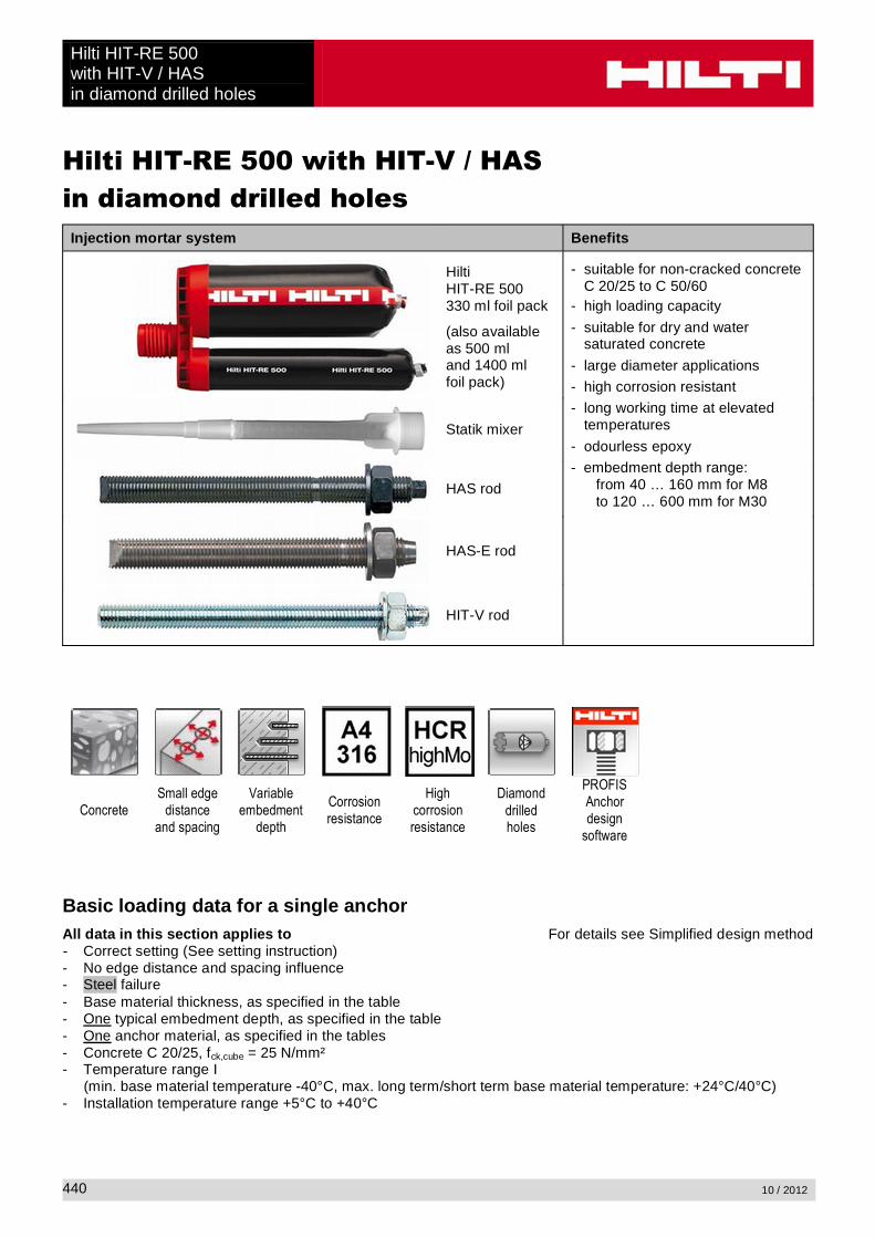
Hilti HIT-RE 500 with HIT-V / HASin diamond drilled holes
Injection mortar system Benefits
HiltiHIT-RE 500330 ml foil pack
(also availableas 500 mland 1400 mlfoil pack)
- suitable for non-cracked concrete C 20/25 to C 50/60
- high loading capacity
- suitable for dry and water saturated concrete
- large diameter applications
- high corrosion resistant
- long working time at elevated temperatures
- odourless epoxy
- embedment depth range:from 40 … 160 mm for M8to 120 … 600 mm for M30
Statik mixer
HAS rod
HAS-E rod
HIT-V rod
ConcreteSmall edge
distance and spacing
Variable embedment
depth
Corrosion resistance
High corrosion resistance
Diamond drilledholes
PROFIS Anchor design
software
Basic loading data for a single anchorAll data in this section applies to For details see Simplified design method- Correct setting (See setting instruction)- No edge distance and spacing influence- Steel failure- Base material thickness, as specified in the table- One typical embedment depth, as specified in the table- One anchor material, as specified in the tables- Concrete C 20/25, fck,cube = 25 N/mm²- Temperature range I
(min. base material temperature -40°C, max. long term/short term base material temperature: +24°C/40°C)- Installation temperature range +5°C to +40°C

Hilti HIT-RE 500with HIT-V / HAS
in diamond drilled holes
10 / 2012 441
Embedment depth a) and base material thickness for the basic loading data. Mean ultimate resistance, characteristic resistance, design resistance, recommended loads.Anchor size M8 M10 M12 M16 M20 M24 M27 M30Typical embedment depth [mm] 80 90 110 125 170 210 240 270Base material thickness [mm] 110 120 140 165 220 270 300 340
a) The allowed range of embedment depth is shown in the setting details. The corresponding load values can be calculated according to the simplified design method.
Mean ultimate resistance: concrete C 20/25 – fck,cube = 25 N/mm², anchor HIT-V 5.8Anchor size M8 M10 M12 M16 M20 M24 M27 M30
Tensile NRu,m HIT-V 5.8 [kN] 18,9 30,5 44,1 83,0 129,2 185,9 229,7 287,2
Shear VRu,m HIT-V 5.8 [kN] 9,5 15,8 22,1 41,0 64,1 92,4 120,8 147,0
Characteristic resistance: concrete C 20/25 – fck,cube = 25 N/mm², anchor HIT-V 5.8Anchor size M8 M10 M12 M16 M20 M24 M27 M30
Tensile NRk HIT-V 5.8 [kN] 18,0 29,0 42,0 66,0 101,5 142,5 173,0 216,3
Shear VRk HIT-V 5.8 [kN] 9,0 15,0 21,0 39,0 61,0 88,0 115,0 140,0
Design resistance: concrete C 20/25 – fck,cube = 25 N/mm², anchor HIT-V 5.8Anchor size M8 M10 M12 M16 M20 M24 M27 M30
Tensile NRd HIT-V 5.8 [kN] 12,0 18,8 27,6 31,4 48,3 67,9 82,4 103,0
Shear VRd HIT-V 5.8 [kN] 7,2 12,0 16,8 31,2 48,8 70,4 92,0 112,0
Recommended loads a): concrete C 20/25 – fck,cube = 25 N/mm², anchor HIT-V 5.8Anchor size M8 M10 M12 M16 M20 M24 M27 M30
Tensile Nrec HIT-V 5.8 [kN] 8,6 13,5 19,7 22,4 34,5 48,5 58,9 73,6
Shear Vrec HIT-V 5.8 [kN] 5,1 8,6 12,0 22,3 34,9 50,3 65,7 80,0
a) With overall partial safety factor for action = 1,4. The partial safety factors for action depend on the type of loading and shall be taken from national regulations.
Service temperature rangeHilti HIT-RE 500 injection mortar may be applied in the temperature ranges given below. An elevated base material temperature may lead to a reduction of the design bond resistance.
Temperature range Base material temperature
Maximum long term base material temperature
Maximum short term base material temperature
Temperature range I -40 °C to +40 °C +24 °C +40 °CTemperature range II -40 °C to +58 °C +35 °C +58 °CTemperature range III -40 °C to +70 °C +43 °C +70 °C
Max short term base material temperatureShort-term elevated base material temperatures are those that occur over brief intervals, e.g. as a result of diurnal cycling.
Max long term base material temperatureLong-term elevated base material temperatures are roughly constant over significant periods of time.

Hilti HIT-RE 500with HIT-V / HASin diamond drilled holes
10 / 2012442
Materials
Mechanical properties of HIT-V / HASHilti technical data
Anchor size M8 M10 M12 M16 M20 M24 M27 M30
Nominal tensile strength fuk
HIT-V/HAS 5.8 [N/mm²] 500 500 500 500 500 500 500 500HIT-V/HAS 8.8 [N/mm²] 800 800 800 800 800 800 800 800HIT-V/HAS -R [N/mm²] 700 700 700 700 700 700 500 500HIT-V/HAS -HCR [N/mm²] 800 800 800 800 800 700 700 700
Yield strength fyk
HIT-V/HAS 5.8 [N/mm²] 400 400 400 400 400 400 400 400HIT-V/HAS 8.8 [N/mm²] 640 640 640 640 640 640 640 640HIT-V/HAS -R [N/mm²] 450 450 450 450 450 450 210 210HIT-V/HAS -HCR [N/mm²] 600 600 600 600 600 400 400 400
Stressed cross-section As
HAS [mm²] 32,8 52,3 76,2 144 225 324 427 519
HIT-V [mm²] 36,6 58,0 84,3 157 245 353 459 561
Moment of resistance W
HAS [mm³] 27,0 54,1 93,8 244 474 809 1274 1706
HIT-V [mm³] 31,2 62,3 109 277 541 935 1387 1874
Material qualityPart MaterialThreaded rod HIT-V(F),HAS 5.8 M8 – M24
Strength class 5.8, A5 > 8% ductile,
Threaded rod HIT-V(F),HAS 8.8 M27 – M30
Strength class 8.8, A5 > 8% ductile,
Threaded rod HIT-V-R, HAS-RStainless steel grade A4, A5 > 8% ductile,class 50 for M27 to M30, 1.4401; 1.4404; 1.4578; 1.4571; 1.4439; 1.4362
Threaded rod HIT-V-HCR,HAS-HCR
High corrosion resistant steel, 1.4529; 1.4565,m = 800 N/mm², Rp 0.2 = 640 N/mm², A5 > 8% ductile
M24 to M30: Rm = 700 N/mm², Rp 0.2 = 400 N/mm², A5 > 8% ductile
WasherISO 7089
Steel galvanized, hot dipped galvanizedStainless steel, 1.4401; 1.4404; 1.4578; 1.4571; 1.4439; 1.4362High corrosion resistant steel, 1.4529; 1.4565
NutEN ISO 4032
Strength class 8,Strength class 70, stainless steel grade A4, 1.4401; 1.4404; 1.4578; 1.4571; 1.4439; 1.4362Strength class 70, high corrosion resistant steel,1.4529; 1.4565
Anchor dimensions
Anchor size M8 M10 M12 M16 M20 M24 M27 M30
Anchor rodHAS, HAS-E,HAS-R, HAS-ERHAS-HCR
M8x
80
M10
x90
M12
x110
M16
x12
5
M20
x17
0
M24
x21
0
M27
x24
0
M30
x27
0
Anchor embedment depth [mm] 80 90 110 125 170 210 240 270
Anchor rodHIT-V, HIT-V-R, HIT-V-HCR
Anchor rods HIT-V (-R / -HCR) are available in variable length
Hilti HIT-RE 500with HIT-V / HAS
in diamond drilled holes
10 / 2012 443
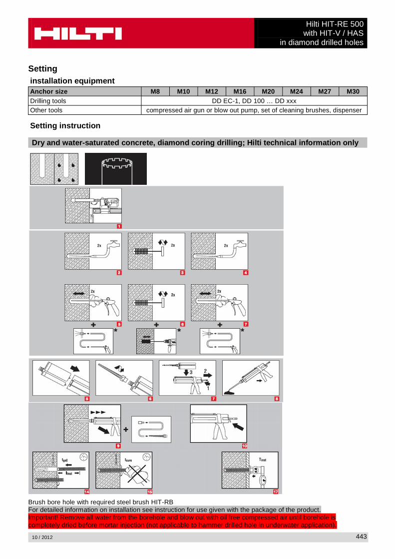
Settinginstallation equipmentAnchor size M8 M10 M12 M16 M20 M24 M27 M30Drilling tools DD EC-1, DD 100 … DD xxxOther tools compressed air gun or blow out pump, set of cleaning brushes, dispenser
Setting instruction
Dry and water-saturated concrete, diamond coring drilling; Hilti technical information only
Brush bore hole with required steel brush HIT-RBFor detailed information on installation see instruction for use given with the package of the product.Important! Remove all water from the borehole and blow out with oil free compressed air until borehole is completely dried before mortar injection (not applicable to hammer drilled hole in underwater application).

Hilti HIT-RE 500with HIT-V / HASin diamond drilled holes
10 / 2012444
Curing time for general conditionsTemperature
of the base materialCuring time before anchor can be
fully loaded tcure
Working time in which anchor can be inserted and adjusted tgel
40 °C 4 h 12 min30 °C to 39 °C 8 h 12 min20 °C to 29 °C 12 h 20 min15 °C to 19 °C 24 h 30min10 °C to 14 °C 48 h 90 min
5 °C to 9 °C 72 h 120 min
Setting detailsAnchor size M8 M10 M12 M16 M20 M24 M27 M30Nominal diameter of drill bit
d0 [mm] 10 12 14 18 24 28 30 35
Effective anchorage and drill hole depth range a)
hef,min [mm] 40 40 48 64 80 96 108 120
hef,max [mm] 160 200 240 320 400 480 540 600
Minimum base material thickness
hmin [mm]hef + 30 mm
hef + 2 d0
Diameter of clearance hole in the fixture
df [mm] 9 12 14 18 22 26 30 33
Minimum spacing smin [mm] 40 50 60 80 100 120 135 150Minimum edge distance
cmin [mm] 40 50 60 80 100 120 135 150
Critical spacing for splitting failure
scr,sp 2 ccr,sp
Critical edge distance for splitting failure b) ccr,sp [mm]
1,0 hef for h / hef
4,6 hef - 1,8 h for 2,0 > h / hef > 1,3
2,26 hef for h / hef 1,3
Critical spacing for concrete cone failure
scr,N 2 ccr,N
Critical edge distance for concrete cone failure c)
ccr,N 1,5 hef
Torque moment d) Tmax [Nm] 10 20 40 80 150 200 270 300
For spacing (edge distance) smaller than critical spacing (critical edge distance) the design loads have to be reduced.
Hilti HIT-RE 500with HIT-V / HAS
in diamond drilled holes
10 / 2012 445
a) hef,min hef ef,max (hef: embedment depth)
b) h: base material thickness (h hmin)
c) The critical edge distance for concrete cone failure depends on the embedment depth hef and the design bond resistance. The simplified formula given in this table is on the save side.
d) This is the maximum recommended torque moment to avoid splitting failure during installation for anchors with minimum spacing and/or edge distance.
Simplified design methodSimplified version of the design method according ETAG 001, TR 029.
Influence of concrete strengthInfluence of edge distanceInfluence of spacingValid for a group of two anchors. (The method may also be applied for anchor groups with more than two anchors or more than one edge distance. The influencing factors must then be considered for each edge distance and spacing. The calculated design loads are then conservative: They will be lower than the exact values according ETAG 001, TR 029. To avoid this, it is recommended to use the anchor design software PROFIS Anchor)
The design method is based on the following simplification:No different loads are acting on individual anchors (no eccentricity)
The values are valid for one anchor.
For more complex fastening applications please use the anchor design software PROFIS Anchor.
Tension loading
The design tensile resistance is the lower value of
- Steel resistance: NRd,s
- Combined pull-out and concrete cone resistance:NRd,p = N0
Rd,p fB,p f1,N f2,N f3,N fh,p fre,N
- Concrete cone resistance: NRd,c = N0Rd,c fB f1,N f2,N f3,N fh,N fre,N
- Concrete splitting resistance (only non-cracked concrete):NRd,sp = N0
Rd,c fB f1,sp f2,sp f3,sp fh,N fre,N

Hilti HIT-RE 500with HIT-V / HASin diamond drilled holes
10 / 2012446
Basic design tensile resistance
Design steel resistance NRd,s
Anchor size M8 M10 M12 M16 M20 M24 M27 M30
NRd,s
HAS 5.8 [kN] 11,3 17,3 25,3 48,0 74,7 106,7 - -HIT-V 5.8 [kN] 12,0 19,3 28,0 52,7 82,0 118,0 153,3 187,3HAS 8.8 [kN] - - - - - - 231,3 281,3HIT-V 8.8 [kN] 19,3 30,7 44,7 84,0 130,7 188,0 244,7 299,3HAS (-E)-R [kN] 12,3 19,8 28,3 54,0 84,0 119,8 75,9 92,0HIT-V-R [kN] 13,9 21,9 31,6 58,8 92,0 132,1 80,4 98,3HAS (-E)-HCR [kN] 18,0 28,0 40,7 76,7 120,0 106,7 144,8 175,7HIT-V-HCR [kN] 19,3 30,7 44,7 84,0 130,7 117,6 152,9 187,1
Design combined pull-out and concrete cone resistance for anchors in diamond drilled holesNRd,p = N0
Rd,p fB,p f1,N f2,N f3,N fh,p fre,N
Anchor size M8 M10 M12 M16 M20 M24 M27 M30Typical embedment depthhef,typ [mm] 80 90 110 125 170 210 240 270
N0Rd,p Temperature range I [kN] 13,4 18,8 27,6 31,4 48,3 67,9 82,4 103,0
N0Rd,p Temperature range II [kN] 10,9 15,3 22,4 25,4 39,1 55,0 66,7 83,4
N0Rd,p Temperature range III [kN] 6,8 9,6 14,0 15,9 24,5 34,4 41,8 52,3
Design concrete cone resistance NRd,c = N0Rd,c fB f1,N f2,N f3,N fh,N fre,N
Design splitting resistance NRd,sp = N0Rd,c fB f1,sp f2,sp f3,sp f h,N fre,N
Data according ETA-04/0027, issue 2009-05-20Anchor size M8 M10 M12 M16 M20 M24 M27 M30N0
Rd,c [kN] 17,2 20,5 27,7 33,6 53,3 73,2 89,4 106,7
Influencing factors
Influence of concrete strength on combined pull-out and concrete cone resistanceConcrete strength designation(ENV 206) C 20/25 C 25/30 C 30/37 C 35/45 C 40/50 C 45/55 C 50/60
fB,p = (fck,cube/25N/mm²)0,1 a) 1 1,02 1,04 1,06 1,07 1,08 1,09a) fck,cube = concrete compressive strength, measured on cubes with 150 mm side length
Influence of embedment depth on combined pull-out and concrete cone resistancefh,p = hef/hef,typ
Influence of concrete strength on concrete cone resistanceConcrete strength designation(ENV 206) C 20/25 C 25/30 C 30/37 C 35/45 C 40/50 C 45/55 C 50/60
fB = (fck,cube/25N/mm²)1/2 a) 1 1,1 1,22 1,34 1,41 1,48 1,55a) fck,cube = concrete compressive strength, measured on cubes with 150 mm side length

Hilti HIT-RE 500with HIT-V / HAS
in diamond drilled holes
10 / 2012 447
Influence of edge distance a)
c/ccr,N0,1 0,2 0,3 0,4 0,5 0,6 0,7 0,8 0,9 1
c/ccr,sp
f1,N = 0,7 + 0,3 c/ccr,N0,73 0,76 0,79 0,82 0,85 0,88 0,91 0,94 0,97 1
f1,sp = 0,7 + 0,3 c/ccr,sp
f2,N = 0,5 (1 + c/ccr,N)0,55 0,60 0,65 0,70 0,75 0,80 0,85 0,90 0,95 1
f2,sp = 0,5 (1 + c/ccr,sp)a) The the edge distance shall not be smaller than the minimum edge distance cmin given in the table with the
setting details. These influencing factors must be considered for every edge distance smaller than the critical edge distance.
Influence of anchor spacing a)
s/scr,N0,1 0,2 0,3 0,4 0,5 0,6 0,7 0,8 0,9 1
s/scr,sp
f3,N = 0,5 (1 + s/scr,N)0,55 0,60 0,65 0,70 0,75 0,80 0,85 0,90 0,95 1
f3,sp = 0,5 (1 + s/scr,sp)a) The anchor spacing shall not be smaller than the minimum anchor spacing smin given in the table with the
setting details. This influencing factor must be considered for every anchor spacing.
Influence of embedment depth on concrete cone resistancefh,N = (hef/hef,typ)
1,5
Influence of reinforcementhef [mm] 40 50 60 70 80 90
fre,N = 0,5 + hef 0,7 a) 0,75 a) 0,8 a) 0,85 a) 0,9 a) 0,95 a) 1a) This factor applies only for dense reinforcement. If in the area of anchorage there is reinforcement with a
spacing mm, then a factor fre = 1may be applied.
Shear loading
The design shear resistance is the lower value of
- Steel resistance: VRd,s
- Concrete pryout resistance: VRd,cp = k lower value of NRd,p and NRd,c
- Concrete edge resistance: VRd,c = V0Rd,c fB fß f h f4 f hef fc
Hilti HIT-RE 500with HIT-V / HASin diamond drilled holes
10 / 2012448
Basic design shear resistance
Design steel resistance VRd,s
Data according ETA-04/0027, issue 2009-05-20Anchor size M8 M10 M12 M16 M20 M24 M27 M30
VRd,s
HAS 5.8 [kN] 6,8 10,4 15,2 28,8 44,8 64,0 - -HIT-V 5.8 [kN] 7,2 12,0 16,8 31,2 48,8 70,4 92,0 112,0HAS 8.8 [kN] - - - - - - 139,2 168,8HIT-V 8.8 [kN] 12,0 18,4 27,2 50,4 78,4 112,8 147,2 179,2HAS (-E)-R [kN] 7,7 12,2 17,3 32,7 50,6 71,8 45,8 55,5HIT-V-R [kN] 8,3 12,8 19,2 35,3 55,1 79,5 48,3 58,8HAS (-E)-HCR [kN] 10,4 16,8 24,8 46,4 72,0 64,0 86,9 105,7HIT-V-HCR [kN] 12,0 18,4 27,2 50,4 78,4 70,9 92,0 112,0
Design concrete pryout resistance VRd,cp = lower valuea) of k NRd,p and k NRd,c
k = 1 for hef < 60 mmk = 2 for hef
a) NRd,p: Design combined pull-out and concrete cone resistanceNRd,c: Design concrete cone resistance
Design concrete edge resistance VRd,c = V0Rd,c fB fß f h f4 f hef fc
Anchor size M8 M10 M12 M16 M20 M24 M27 M30Non-cracked concreteV0
Rd,c [kN] 5,9 8,6 11,6 18,7 27,0 36,6 44,5 53,0
Influencing factors
Influence of concrete strengthConcrete strength designation(ENV 206) C 20/25 C 25/30 C 30/37 C 35/45 C 40/50 C 45/55 C 50/60
fB = (fck,cube/25N/mm²)1/2 a) 1 1,1 1,22 1,34 1,41 1,48 1,55a) fck,cube = concrete compressive strength, measured on cubes with 150 mm side length
Influence of angle between load applied and the direction perpendicular to the free edgeAngle ß 0° 10° 20° 30° 40° 50° 60° 70° 80° 90°
2cos
1
V
f1 1,01 1,05 1,13 1,24 1,40 1,64 1,97 2,32 2,50
Influence of base material thicknessh/c 0,15 0,3 0,45 0,6 0,75 0,9 1,05 1,2 1,35
f h = {h/(1,5 c)} 1/2 0,32 0,45 0,55 0,63 0,71 0,77 0,84 0,89 0,95 1,00

Hilti HIT-RE 500with HIT-V / HAS
in diamond drilled holes
10 / 2012 449
Influence of anchor spacing and edge distance a) for concrete edge resistance: f4
f4 = (c/hef)1,5 (1 + s / [3 c]) 0,5
c/hefSingle anchor
Group of two anchors s/hef
0,75 1,50 2,25 3,00 3,75 4,50 5,25 6,00 6,75 7,50 8,25 9,00 9,75 ����� �����0,50 0,35 0,27 0,35 0,35 0,35 0,35 0,35 0,35 0,35 0,35 0,35 0,35 0,35 0,35 0,35 0,350,75 0,65 0,43 0,54 0,65 0,65 0,65 0,65 0,65 0,65 0,65 0,65 0,65 0,65 0,65 0,65 0,651,00 1,00 0,63 0,75 0,88 1,00 1,00 1,00 1,00 1,00 1,00 1,00 1,00 1,00 1,00 1,00 1,001,25 1,40 0,84 0,98 1,12 1,26 1,40 1,40 1,40 1,40 1,40 1,40 1,40 1,40 1,40 1,40 1,401,50 1,84 1,07 1,22 1,38 1,53 1,68 1,84 1,84 1,84 1,84 1,84 1,84 1,84 1,84 1,84 1,841,75 2,32 1,32 1,49 1,65 1,82 1,98 2,15 2,32 2,32 2,32 2,32 2,32 2,32 2,32 2,32 2,322,00 2,83 1,59 1,77 1,94 2,12 2,30 2,47 2,65 2,83 2,83 2,83 2,83 2,83 2,83 2,83 2,832,25 3,38 1,88 2,06 2,25 2,44 2,63 2,81 3,00 3,19 3,38 3,38 3,38 3,38 3,38 3,38 3,382,50 3,95 2,17 2,37 2,57 2,77 2,96 3,16 3,36 3,56 3,76 3,95 3,95 3,95 3,95 3,95 3,952,75 4,56 2,49 2,69 2,90 3,11 3,32 3,52 3,73 3,94 4,15 4,35 4,56 4,56 4,56 4,56 4,563,00 5,20 2,81 3,03 3,25 3,46 3,68 3,90 4,11 4,33 4,55 4,76 4,98 5,20 5,20 5,20 5,203,25 5,86 3,15 3,38 3,61 3,83 4,06 4,28 4,51 4,73 4,96 5,18 5,41 5,63 5,86 5,86 5,863,50 6,55 3,51 3,74 3,98 4,21 4,44 4,68 4,91 5,14 5,38 5,61 5,85 6,08 6,31 6,55 6,553,75 7,26 3,87 4,12 4,36 4,60 4,84 5,08 5,33 5,57 5,81 6,05 6,29 6,54 6,78 7,02 7,264,00 8,00 4,25 4,50 4,75 5,00 5,25 5,50 5,75 6,00 6,25 6,50 6,75 7,00 7,25 7,50 7,754,25 8,76 4,64 4,90 5,15 5,41 5,67 5,93 6,18 6,44 6,70 6,96 7,22 7,47 7,73 7,99 8,254,50 9,55 5,04 5,30 5,57 5,83 6,10 6,36 6,63 6,89 7,16 7,42 7,69 7,95 8,22 8,49 8,754,75 10,35 5,45 5,72 5,99 6,27 6,54 6,81 7,08 7,36 7,63 7,90 8,17 8,45 8,72 8,99 9,265,00 11,18 5,87 6,15 6,43 6,71 6,99 7,27 7,55 7,83 8,11 8,39 8,66 8,94 9,22 9,50 9,785,25 12,03 6,30 6,59 6,87 7,16 7,45 7,73 8,02 8,31 8,59 8,88 9,17 9,45 9,74 10,02 10,315,50 12,90 6,74 7,04 7,33 7,62 7,92 8,21 8,50 8,79 9,09 9,38 9,67 9,97 10,26 10,55 10,85
a) The anchor spacing and the edge distance shall not be smaller than the minimum anchor spacing smin and the minimum edge distance cmin.
Influence of embedment depthhef/d 4 4,5 5 6 7 8 9 10 11
f hef = 0,05 (hef / d)1,68 0,51 0,63 0,75 1,01 1,31 1,64 2,00 2,39 2,81
hef/d 12 13 14 15 16 17 18 19 20
f hef = 0,05 (hef / d)1,68 3,25 3,72 4,21 4,73 5,27 5,84 6,42 7,04 7,67
Influence of edge distance a)
c/d 4 6 8 10 15 20 30 40
fc = (d / c)0,19 0,77 0,71 0,67 0,65 0,60 0,57 0,52 0,50a) The edge distance shall not be smaller than the minimum edge distance cmin.
Combined tension and shear loading
For combined tension and shear loading see section “Anchor Design”.

Hilti HIT-RE 500with HIS-(R)N
10 / 2012450
Hilti HIT-RE 500 with HIS-(R)NInjection mortar system Benefits
HiltiHIT-RE 500330 ml foil pack
(also available as 500 mland 1400 mlfoil pack)
- suitable for non-cracked concrete C 20/25 to C 50/60
- high loading capacity
- suitable for dry and water saturated concrete
- under water application for hammer drilled holes
- long working time at elevated temperatures
- odourless epoxyStatik mixer
HIS-(R)N sleeve
ConcreteSmall edge
distance and spacing
Fire resistance
Corrosion resistance
European Technical Approval
CE conformity
Diamond drilledholes
PROFIS Anchor design
software
Approvals / certificatesDescription Authority / Laboratory No. / date of issueEuropean technical approval a) DIBt, Berlin ETA-04/0027 / 2009-05-20
Fire test report IBMB, BrunswickUB 3565 / 4595 / 2006-10-29UB 3588 / 4825 / 2005-11-15
Assessment report (fire) warringtonfireWF 166402 / 2007-10-26 & suppl. WF 172920 / 2008-05-27
a) All data given in this section according ETA-04/0027, issue 2009-05-20.
Basic loading data (for a single anchor)All data in this section applies to For details see Simplified design method- Correct setting (See setting instruction)- No edge distance and spacing influence- Steel failure- Screw strength class 8.8- Base material thickness, as specified in the table- One typical embedment depth, as specified in the table- One anchor material, as specified in the tables- Concrete C 20/25, fck,cube = 25 N/mm²- Temperate range I
(min. base material temperature -40°C, max. long term/short term base material temperature: +24°C/40°C)- Installation temperature range +5°C to +40°C
Hilti HIT-RE 500with HIS-(R)N
10 / 2012 451
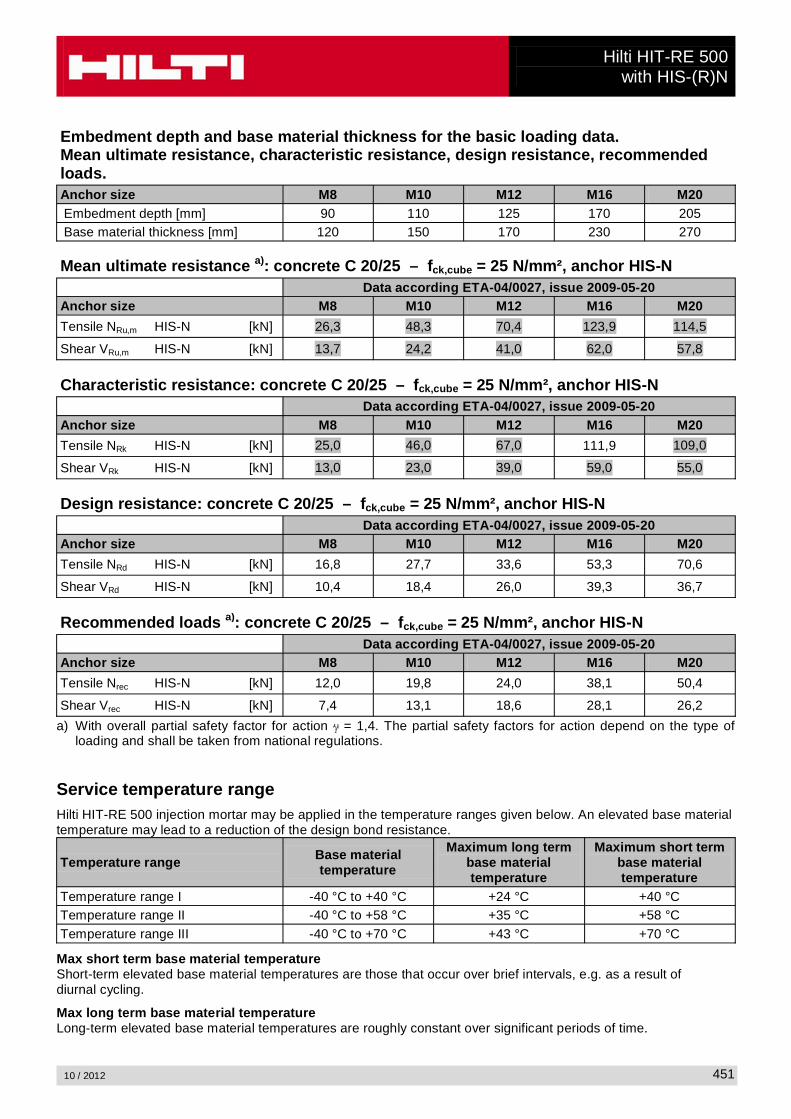
Embedment depth and base material thickness for the basic loading data.Mean ultimate resistance, characteristic resistance, design resistance, recommended loads.Anchor size M8 M10 M12 M16 M20Embedment depth [mm] 90 110 125 170 205Base material thickness [mm] 120 150 170 230 270
Mean ultimate resistance a): concrete C 20/25 – fck,cube = 25 N/mm², anchor HIS-NData according ETA-04/0027, issue 2009-05-20
Anchor size M8 M10 M12 M16 M20
Tensile NRu,m HIS-N [kN] 26,3 48,3 70,4 123,9 114,5
Shear VRu,m HIS-N [kN] 13,7 24,2 41,0 62,0 57,8
Characteristic resistance: concrete C 20/25 – fck,cube = 25 N/mm², anchor HIS-NData according ETA-04/0027, issue 2009-05-20
Anchor size M8 M10 M12 M16 M20
Tensile NRk HIS-N [kN] 25,0 46,0 67,0 111,9 109,0
Shear VRk HIS-N [kN] 13,0 23,0 39,0 59,0 55,0
Design resistance: concrete C 20/25 – fck,cube = 25 N/mm², anchor HIS-NData according ETA-04/0027, issue 2009-05-20
Anchor size M8 M10 M12 M16 M20
Tensile NRd HIS-N [kN] 16,8 27,7 33,6 53,3 70,6
Shear VRd HIS-N [kN] 10,4 18,4 26,0 39,3 36,7
Recommended loads a): concrete C 20/25 – fck,cube = 25 N/mm², anchor HIS-NData according ETA-04/0027, issue 2009-05-20
Anchor size M8 M10 M12 M16 M20
Tensile Nrec HIS-N [kN] 12,0 19,8 24,0 38,1 50,4
Shear Vrec HIS-N [kN] 7,4 13,1 18,6 28,1 26,2
a) With overall partial safety factor for action = 1,4. The partial safety factors for action depend on the type of loading and shall be taken from national regulations.
Service temperature rangeHilti HIT-RE 500 injection mortar may be applied in the temperature ranges given below. An elevated base material temperature may lead to a reduction of the design bond resistance.
Temperature range Base material temperature
Maximum long term base material temperature
Maximum short term base material temperature
Temperature range I -40 °C to +40 °C +24 °C +40 °CTemperature range II -40 °C to +58 °C +35 °C +58 °CTemperature range III -40 °C to +70 °C +43 °C +70 °C
Max short term base material temperatureShort-term elevated base material temperatures are those that occur over brief intervals, e.g. as a result of diurnal cycling.
Max long term base material temperatureLong-term elevated base material temperatures are roughly constant over significant periods of time.

Hilti HIT-RE 500with HIS-(R)N
10 / 2012452
Materials
Mechanical properties of HIS-(R)NData according ETA-04/0027, issue 2009-05-20
Anchor size M8 M10 M12 M16 M20
Nominal tensile strength fuk
HIS-N [N/mm²] 490 490 460 460 460Screw 8.8 [N/mm²] 800 800 800 800 800HIS-RN [N/mm²] 700 700 700 700 700Screw A4-70 [N/mm²] 700 700 700 700 700
Yield strength fyk
HIS-N [N/mm²] 410 410 375 375 375Screw 8.8 [N/mm²] 640 640 640 640 640HIS-RN [N/mm²] 350 350 350 350 350Screw A4-70 [N/mm²] 450 450 450 450 450
Stressed cross-section As
HIS-(R)N [mm²] 51,5 108,0 169,1 256,1 237,6
Screw [mm²] 36,6 58 84,3 157 245
Moment of resistance W
HIS-(R)N [mm³] 145 430 840 1595 1543Screw [mm³] 31,2 62,3 109 277 541
Material qualityPart Materialinternally threaded sleeves a)
HIS-NC-steel 1.0718, steel galvanized 5 m
internally threaded sleeves b)
HIS-RN stainless steel 1.4401 and 1.4571
a) related fastening screw: strength class 8.8, A5 > 8% Ductilesteel galvanized 5 m
b) related fastening screw: strength class 70, A5 > 8% Ductilestainless steel 1.4401; 1.4404; 1.4578; 1.4571; 1.4439; 1.4362
Anchor dimensions
Anchor size M8 M10 M12 M16 M20
Internal sleeveHIS-(R)N
M8x90 M10x110 M12x125 M16x170 M20x205
Anchor embedment depth [mm] 90 110 125 170 205
Setting
installation equipmentAnchor size M8 M10 M12 M16 M20Rotary hammer TE 2 – TE 16 TE 40 – TE 70Other tools compressed air gun or blow out pump, set of cleaning brushes, dispenserAdditionalHilti recommended tools DD EC-1, DD 100 … DD xxx a)
a) For anchors in diamond drilled holes load values for combined pull-out and concrete cone resistance have to be reduced (see section “Setting instruction”)

Hilti HIT-RE 500with HIS-(R)N
10 / 2012 453
Setting instruction
Dry and water-saturated concrete, hammer drilling
a)
a) Note: Manual cleaning for HIS-(R)N M8 and HIS-(R)N M10 only!Brush bore hole with required steel brush HIT-RBFor detailed information on installation see instruction for use given with the package of the product.

Hilti HIT-RE 500with HIS-(R)N
10 / 2012454
Water filled bore hole or submerged, hammer drilling
Brush bore hole with required steel brush HIT-RBFor detailed information on installation see instruction for use given with the package of the product.

Hilti HIT-RE 500with HIS-(R)N
10 / 2012 455
Dry and water-saturated concrete, diamond coring drilling; Hilti technical information only
For anchors in diamond drilled holes load values for combined pull-out and concrete cone resistance have to be reduced. Load reduction factor: 0.7
Brush bore hole with required steel brush HIT-RBFor detailed information on installation see instruction for use given with the package of the product.Important! Remove all water from the borehole and blow out with oil free compressed air until borehole is completely dried before mortar injection (not applicable to hammer drilled hole in underwater application).

Hilti HIT-RE 500with HIS-(R)N
10 / 2012456
Curing time for general conditionsData according ETA-04/0027, issue 2009-05-20
Temperatureof the base material
Working time in which anchorcan be inserted and adjusted tgel
Curing time before anchorcan be fully loaded tcure
40 °C 12 min 4 h30 °C to 39 °C 12 min 8 h20 °C to 29 °C 20 min 12 h15 °C to 19 °C 30 min 24 h10 °C to 14 °C 90 min 48 h
5 °C to 9 °C 120 min 72 h
For dry concrete curing times may be reduced according to the following table.For installation temperatures below +5 °C all load values have to be reduced according to the load reduction factors given below.
Curing time for dry concreteAdditional Hilti technical data
Temperatureof the
base material
Reduced curing time before anchor can be
fully loaded tcure,dry
Working time in which anchor can be inserted
and adjusted tgel
Load reduction factor
40 °C 4 h 12 min 130 °C 8 h 12 min 120 °C 12 h 20 min 115 °C 18 h 30 min 110 °C 24 h 90 min 15 °C 36 h 120 min 10 °C 50 h 3 h 0,7-5 °C 72 h 4 h 0,6

Hilti HIT-RE 500with HIS-(R)N
10 / 2012 457
Setting detailsData according ETA-04/0027, issue 2009-05-20
Anchor size M8 M10 M12 M16 M20Nominal diameter of drill bit
d0 [mm] 14 18 22 28 32
Diameter of element d [mm] 12,5 16,5 20,5 25,4 27,6
Effective anchorage and drill hole depth
hef [mm] 90 110 125 170 205
Minimum base material thickness
hmin [mm] 120 150 170 230 270
Diameter of clearance hole in the fixture df [mm] 9 12 14 18 22
Thread engagement length; min - max hs [mm] 8-20 10-25 12-30 16-40 20-50
Minimum spacing smin [mm] 40 45 55 65 90Minimum edge distance cmin [mm] 40 45 55 65 90
Critical spacing for splitting failure scr,sp 2 ccr,sp
Critical edge distance for splitting failure a) ccr,sp [mm]
1,0 hef for h / hef
4,6 hef - 1,8 h for 2,0 > h / hef > 1,3
2,26 hef for h / hef 1,3
Critical spacing for concrete cone failure scr,N 2 ccr,N
Critical edge distance for concrete cone failure c)
ccr,N 1,5 hef
Torque moment c) Tmax [Nm] 10 20 40 80 150
For spacing (edge distance) smaller than critical spacing (critical edge distance) the design loads have to be reduced.
a) h: base material thickness (h hmin)
b) The critical edge distance for concrete cone failure depends on the embedment depth hef and the design bond resistance. The simplified formula given in this table is on the save side.
c) This is the maximum recommended torque moment to avoid splitting failure during installation for anchors with minimum spacing and/or edge distance.

Hilti HIT-RE 500with HIS-(R)N
10 / 2012458
Simplified design methodSimplified version of the design method according ETAG 001, TR 029. Design resistance according data given in ETA-04/0027, issue 2009-05-20.
Influence of concrete strengthInfluence of edge distanceInfluence of spacingValid for a group of two anchors. (The method may also be applied for anchor groups with more than two anchors or more than one edge distance. The influencing factors must then be considered for each edge distance and spacing. The calculated design loads are then on the save side: They will be lower than the exact values according ETAG 001, TR 029. To avoid this, it is recommended to use the anchor design software PROFIS anchor)
The design method is based on the following simplification:No different loads are acting on individual anchors (no eccentricity)
The values are valid for one anchor.
For more complex fastening applications please use the anchor design software PROFIS Anchor.
Tension loading
The design tensile resistance is the lower value of- Steel resistance: NRd,s
- Combined pull-out and concrete cone resistance:NRd,p = N0
Rd,p fB,p f1,N f2,N f3,N fh,p fre,N
- Concrete cone resistance: NRd,c = N0Rd,c fB f1,N f2,N f3,N fh,N fre,N
- Concrete splitting resistance (only non-cracked concrete):NRd,sp = N0
Rd,c fB f1,sp f2,sp f3,sp fh,N fre,N
Basic design tensile resistance
Design steel resistance NRd,s
Data according ETA-04/0027, issue 2009-05-20Anchor size M8 M10 M12 M16 M20
NRd,sHIS-N [kN] 16,8 30,7 44,7 80,3 74,1HIS-RN [kN] 13,9 21,9 31,6 58,8 69,2
Design combined pull-out and concrete cone resistance a)
NRd,p = N0Rd,p fB,p f1,N f2,N f3,N fh,p fre,N
Data according ETA-04/0027, issue 2009-05-20Anchor size M8 M10 M12 M16 M20Embedment depthhef [mm] 90 110 125 170 205
N0Rd,p Temperature range I [kN] 19,0 28,6 45,2 81,0 95,2
N0Rd,p Temperature range II [kN] 16,7 23,8 35,7 66,7 81,0
N0Rd,p Temperature range III [kN] 9,5 14,3 19,0 35,7 45,2
a) Additional Hilti technical data (not part of ETA-04/0027, issue 2009-05-20):The design values for combined pull-out and concrete cone resistance may be increased by 20 % for anchor installation in dry concrete (concrete not in contact with water before/during installation and curing).

Hilti HIT-RE 500with HIS-(R)N
10 / 2012 459
Design concrete cone resistance a) NRd,c = N0Rd,c fB f1,N f2,N f3,N fh,N fre,N
Design splitting resistance NRd,spa) = N0
Rd,c fB f1,sp f2,sp f3,sp f h,N fre,N
Data according ETA-04/0027, issue 2009-05-20Anchor size M8 M10 M12 M16 M20N0
Rd,c [kN] 20,5 27,7 33,6 53,3 70,6a) Additional Hilti technical data (not part of ETA-04/0027, issue 2009-05-20):
The design values for concrete cone and splitting resistance may be increased by 20 % for anchor installation in dry concrete (concrete not in contact with water before/during installation and curing).
Influencing factors
Influence of concrete strength on combined pull-out and concrete cone resistanceConcrete strength designation(ENV 206) C 20/25 C 25/30 C 30/37 C 35/45 C 40/50 C 45/55 C 50/60
fB,p = (fck,cube/25N/mm²)0,1 a) 1 1,02 1,04 1,06 1,07 1,08 1,09a) fck,cube = concrete compressive strength, measured on cubes with 150 mm side length
Influence of embedment depth on combined pull-out and concrete cone resistancefh,p = 1
Influence of concrete strength on concrete cone resistanceConcrete strength designation(ENV 206) C 20/25 C 25/30 C 30/37 C 35/45 C 40/50 C 45/55 C 50/60
fB = (fck,cube/25N/mm²)1/2 a) 1 1,1 1,22 1,34 1,41 1,48 1,55a) fck,cube = concrete compressive strength, measured on cubes with 150 mm side length
Influence of edge distance a)
c/ccr,N0,1 0,2 0,3 0,4 0,5 0,6 0,7 0,8 0,9 1
c/ccr,sp
f1,N = 0,7 + 0,3 c/ccr,N0,73 0,76 0,79 0,82 0,85 0,88 0,91 0,94 0,97 1
f1,sp = 0,7 + 0,3 c/ccr,sp
f2,N = 0,5 (1 + c/ccr,N)0,55 0,60 0,65 0,70 0,75 0,80 0,85 0,90 0,95 1
f2,sp = 0,5 (1 + c/ccr,sp)a) The the edge distance shall not be smaller than the minimum edge distance cmin given in the table with the
setting details. These influencing factors must be considered for every edge distance smaller than the critical edge distance.
Influence of anchor spacing a)
s/scr,N0,1 0,2 0,3 0,4 0,5 0,6 0,7 0,8 0,9 1
s/scr,sp
f3,N = 0,5 (1 + s/scr,N)0,55 0,60 0,65 0,70 0,75 0,80 0,85 0,90 0,95 1
f3,sp = 0,5 (1 + s/scr,sp)a) The anchor spacing shall not be smaller than the minimum anchor spacing smin given in the table with the
setting details. This influencing factor must be considered for every anchor spacing.
Influence of embedment depth on concrete cone resistancefh,N = 1

Hilti HIT-RE 500with HIS-(R)N
10 / 2012460
Influence of reinforcementhef [mm] 80 90
fre,N = 0,5 + hef 0,9 a) 0,95 a) 1a) This factor applies only for dense reinforcement. If in the area of anchorage there is reinforcement with a
spacing mm, then a factor fre = 1may be applied.
Shear loading
The design shear resistance is the lower value of
- Steel resistance: VRd,s
- Concrete pryout resistance: VRd,cp = k lower value of NRd,p and NRd,c
- Concrete edge resistance: VRd,c = V0Rd,c fB fß f h f4 f hef fc
Basic design shear resistance
Design steel resistance VRd,s
Data according ETA-04/0027, issue 2009-05-20Anchor size M8 M10 M12 M16 M20
VRd,sHIS-N [kN] 10,4 18,4 26,0 39,3 36,7HIS-RN [kN] 8,3 12,8 19,2 35,3 41,5
Design concrete pryout resistance VRd,cp = lower valuea) of k NRd,p and k NRd,c
k = 1 for hef < 60 mmk = 2 for hef
a) NRd,p: Design combined pull-out and concrete cone resistanceNRd,c: Design concrete cone resistance
Design concrete edge resistance VRd,c = V0Rd,c fB fß f h f4 f hef fc
Anchor size M8 M10 M12 M16 M20Non-cracked concreteV0
Rd,c [kN] 12,4 19,6 28,2 40,2 46,2
Influencing factors
Influence of concrete strengthConcrete strength designation(ENV 206) C 20/25 C 25/30 C 30/37 C 35/45 C 40/50 C 45/55 C 50/60
fB = (fck,cube/25N/mm²)1/2 a) 1 1,1 1,22 1,34 1,41 1,48 1,55a) fck,cube = concrete compressive strength, measured on cubes with 150 mm side length

Hilti HIT-RE 500with HIS-(R)N
10 / 2012 461
Influence of angle between load applied and the direction perpendicular to the free edgeAngle ß 0° 10° 20° 30° 40° 50° 60° 70° 80° 90°
1f
1 1,01 1,05 1,13 1,24 1,40 1,64 1,97 2,32 2,50
Influence of base material thicknessh/c 0,15 0,3 0,45 0,6 0,75 0,9 1,05 1,2 1,35
f h = {h/(1,5 c)} 1/2 0,32 0,45 0,55 0,63 0,71 0,77 0,84 0,89 0,95 1,00
Influence of anchor spacing and edge distance a) for concrete edge resistance: f4
f4 = (c/hef)1,5 (1 + s / [3 c]) 0,5
c/hefSingle anchor
Group of two anchors s/hef
0,75 1,50 2,25 3,00 3,75 4,50 5,25 6,00 6,75 7,50 8,25 9,00 9,75 ����� �����0,50 0,35 0,27 0,35 0,35 0,35 0,35 0,35 0,35 0,35 0,35 0,35 0,35 0,35 0,35 0,35 0,350,75 0,65 0,43 0,54 0,65 0,65 0,65 0,65 0,65 0,65 0,65 0,65 0,65 0,65 0,65 0,65 0,651,00 1,00 0,63 0,75 0,88 1,00 1,00 1,00 1,00 1,00 1,00 1,00 1,00 1,00 1,00 1,00 1,001,25 1,40 0,84 0,98 1,12 1,26 1,40 1,40 1,40 1,40 1,40 1,40 1,40 1,40 1,40 1,40 1,401,50 1,84 1,07 1,22 1,38 1,53 1,68 1,84 1,84 1,84 1,84 1,84 1,84 1,84 1,84 1,84 1,841,75 2,32 1,32 1,49 1,65 1,82 1,98 2,15 2,32 2,32 2,32 2,32 2,32 2,32 2,32 2,32 2,322,00 2,83 1,59 1,77 1,94 2,12 2,30 2,47 2,65 2,83 2,83 2,83 2,83 2,83 2,83 2,83 2,832,25 3,38 1,88 2,06 2,25 2,44 2,63 2,81 3,00 3,19 3,38 3,38 3,38 3,38 3,38 3,38 3,382,50 3,95 2,17 2,37 2,57 2,77 2,96 3,16 3,36 3,56 3,76 3,95 3,95 3,95 3,95 3,95 3,952,75 4,56 2,49 2,69 2,90 3,11 3,32 3,52 3,73 3,94 4,15 4,35 4,56 4,56 4,56 4,56 4,563,00 5,20 2,81 3,03 3,25 3,46 3,68 3,90 4,11 4,33 4,55 4,76 4,98 5,20 5,20 5,20 5,203,25 5,86 3,15 3,38 3,61 3,83 4,06 4,28 4,51 4,73 4,96 5,18 5,41 5,63 5,86 5,86 5,863,50 6,55 3,51 3,74 3,98 4,21 4,44 4,68 4,91 5,14 5,38 5,61 5,85 6,08 6,31 6,55 6,553,75 7,26 3,87 4,12 4,36 4,60 4,84 5,08 5,33 5,57 5,81 6,05 6,29 6,54 6,78 7,02 7,264,00 8,00 4,25 4,50 4,75 5,00 5,25 5,50 5,75 6,00 6,25 6,50 6,75 7,00 7,25 7,50 7,754,25 8,76 4,64 4,90 5,15 5,41 5,67 5,93 6,18 6,44 6,70 6,96 7,22 7,47 7,73 7,99 8,254,50 9,55 5,04 5,30 5,57 5,83 6,10 6,36 6,63 6,89 7,16 7,42 7,69 7,95 8,22 8,49 8,754,75 10,35 5,45 5,72 5,99 6,27 6,54 6,81 7,08 7,36 7,63 7,90 8,17 8,45 8,72 8,99 9,265,00 11,18 5,87 6,15 6,43 6,71 6,99 7,27 7,55 7,83 8,11 8,39 8,66 8,94 9,22 9,50 9,785,25 12,03 6,30 6,59 6,87 7,16 7,45 7,73 8,02 8,31 8,59 8,88 9,17 9,45 9,74 10,02 10,315,50 12,90 6,74 7,04 7,33 7,62 7,92 8,21 8,50 8,79 9,09 9,38 9,67 9,97 10,26 10,55 10,85
a) The anchor spacing and the edge distance shall not be smaller than the minimum anchor spacing smin and the minimum edge distance cmin.
Influence of embedment depthAnchor size M8 M10 M12 M16 M20
f hef = 1,38 1,21 1,04 1,22 1,45
Influence of edge distance a)
c/d 4 6 8 10 15 20 30 40
fc = (d / c)0,19 0,77 0,71 0,67 0,65 0,60 0,57 0,52 0,50a) The edge distance shall not be smaller than the minimum edge distance cmin.

Hilti HIT-RE 500with HIS-(R)N
10 / 2012462
Combined tension and shear loading
For combined tension and shear loading see section “Anchor Design”.
Precalculated valuesRecommended loads can be calculated by dividing the design resistance by an overall partial safety factor for action = 1,4. The partial safety factors for action depend on the type of loading and shall be taken from national regulations.
Design resistance: concrete C 20/25 – fck,cube = 25 N/mm², Temperature range I
Data according ETA-04/0027, issue 2009-05-20Anchor size M8 M10 M12 M16 M20Embedment depth hef = [mm] 90 110 125 170 205Base material thickness hmin= [mm] 120 150 170 230 270
Tensile NRd: single anchor, no edge effects
HIS-N [kN] 16,8 27,7 33,6 53,3 70,6
HIS-RN [kN] 13,9 21,9 31,6 53,3 69,2
Shear VRd: single anchor, no edge effects, without lever arm
HIS-N [kN] 10,4 18,4 26,0 39,3 36,7
HIS-RN [kN] 8,3 12,8 19,2 35,3 41,5
Design resistance: concrete C 20/25 – fck,cube = 25 N/mm², Temperature range I
Data according ETA-04/0027, issue 2009-05-20Anchor size M8 M10 M12 M16 M20Embedment depth hef = [mm] 90 110 125 170 205Base material thickness hmin= [mm] 120 150 170 230 270Edge distance c = cmin= [mm] 40 45 55 65 90
Tensile NRd: single anchor, min. edge distance (c = cmin)
HIS-(R)N [kN] 9,4 12,4 15,4 23,5 32,0
Shear VRd: single anchor, min. edge distance (c = cmin) , without lever arm
HIS-(R)N [kN] 4,2 5,5 7,6 10,8 17,2
Design resistance: concrete C 20/25 – fck,cube = 25 N/mm², Temperature range I(load values are valid for single anchor)
Data according ETA-04/0027, issue 2009-05-20Anchor size M8 M10 M12 M16 M20Embedment depth hef = [mm] 90 110 125 170 205Base material thickness hmin= [mm] 120 150 170 230 270Spacing s = smin= [mm] 40 45 55 65 90
Tensile NRd: double anchor, no edge effects, min. spacing (s = smin)
HIS-(R)N [kN] 11,2 15,2 18,5 29,0 38,8
Shear VRd: double anchor, no edge effects, min. spacing (s = smin) , without lever arm
HIS-N [kN] 10,4 18,4 26,0 39,3 36,7
HIS-RN [kN] 8,3 12,8 19,2 35,3 41,5

Hilti HIT-RE 500with HIS-(R)N
10 / 2012 463

Hilti HIT-RE 500with rebarin hammer drilled holes
10 / 2012464
Hilti HIT-RE 500 with rebar in hammer drilled holesInjection mortar system Benefits
HiltiHIT-RE 500330 ml foil pack
(also available as 500 mland 1400 mlfoil pack)
- suitable for non-cracked concrete C 20/25 to C 50/60
- high loading capacity
- suitable for dry and water saturated concrete
- under water application
- large diameter applications
- long working time at elevated temperatures
- odourless epoxy
- embedment depth range:from 60 … 160 mm for Ø8to 128 … 640 mm for Ø32
Statik mixer
rebar BSt 500 S
ConcreteSmall edge
distance and spacing
Variable embedment
depth
European Technical Approval
CE conformity
PROFIS Anchor design
software
Approvals / certificatesDescription Authority / Laboratory No. / date of issueEuropean technical approval a) DIBt, Berlin ETA-04/0027 / 2009-05-20
a) All data given in this section according ETA-04/0027, issue 2009-05-20.
Basic loading data (for a single anchor)All data in this section applies to For details see Simplified design method- Correct setting (See setting instruction)- No edge distance and spacing influence- Steel failure- Base material thickness, as specified in the table- One typical embedment depth, as specified in the table- One anchor material, as specified in the tables- Concrete C 20/25, fck,cube = 25 N/mm²- Temperate range I
(min. base material temperature -40°C, max. long term/short term base material temperature: +24°C/40°C)- Installation temperature range +5°C to +40°C
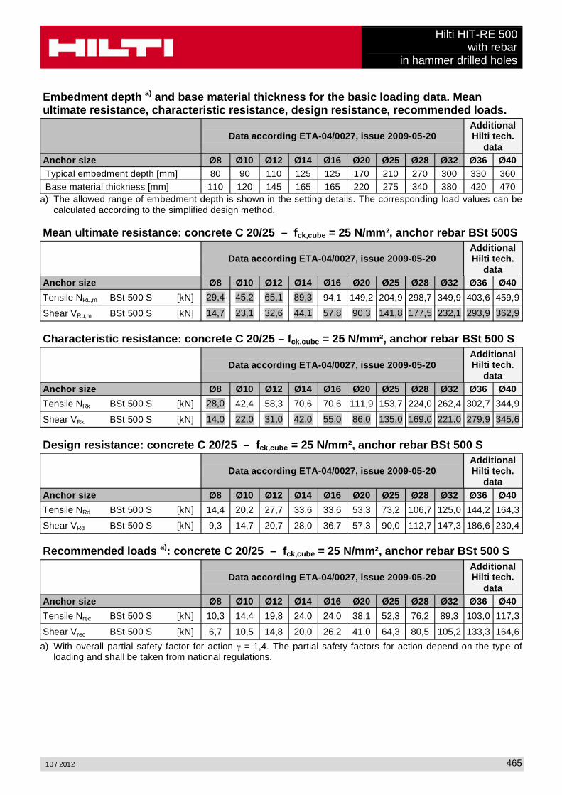
Hilti HIT-RE 500with rebar
in hammer drilled holes
10 / 2012 465
Embedment depth a) and base material thickness for the basic loading data. Mean ultimate resistance, characteristic resistance, design resistance, recommended loads.
Data according ETA-04/0027, issue 2009-05-20Additional Hilti tech.
dataAnchor size Ø8 Ø10 Ø12 Ø14 Ø16 Ø20 Ø25 Ø28 Ø32 Ø36 Ø40Typical embedment depth [mm] 80 90 110 125 125 170 210 270 300 330 360Base material thickness [mm] 110 120 145 165 165 220 275 340 380 420 470
a) The allowed range of embedment depth is shown in the setting details. The corresponding load values can be calculated according to the simplified design method.
Mean ultimate resistance: concrete C 20/25 – fck,cube = 25 N/mm², anchor rebar BSt 500S
Data according ETA-04/0027, issue 2009-05-20Additional Hilti tech.
dataAnchor size Ø8 Ø10 Ø12 Ø14 Ø16 Ø20 Ø25 Ø28 Ø32 Ø36 Ø40
Tensile NRu,m BSt 500 S [kN] 29,4 45,2 65,1 89,3 94,1 149,2 204,9 298,7 349,9 403,6 459,9
Shear VRu,m BSt 500 S [kN] 14,7 23,1 32,6 44,1 57,8 90,3 141,8 177,5 232,1 293,9 362,9
Characteristic resistance: concrete C 20/25 – fck,cube = 25 N/mm², anchor rebar BSt 500 S
Data according ETA-04/0027, issue 2009-05-20Additional Hilti tech.
dataAnchor size Ø8 Ø10 Ø12 Ø14 Ø16 Ø20 Ø25 Ø28 Ø32 Ø36 Ø40
Tensile NRk BSt 500 S [kN] 28,0 42,4 58,3 70,6 70,6 111,9 153,7 224,0 262,4 302,7 344,9
Shear VRk BSt 500 S [kN] 14,0 22,0 31,0 42,0 55,0 86,0 135,0 169,0 221,0 279,9 345,6
Design resistance: concrete C 20/25 – fck,cube = 25 N/mm², anchor rebar BSt 500 S
Data according ETA-04/0027, issue 2009-05-20Additional Hilti tech.
dataAnchor size Ø8 Ø10 Ø12 Ø14 Ø16 Ø20 Ø25 Ø28 Ø32 Ø36 Ø40
Tensile NRd BSt 500 S [kN] 14,4 20,2 27,7 33,6 33,6 53,3 73,2 106,7 125,0 144,2 164,3
Shear VRd BSt 500 S [kN] 9,3 14,7 20,7 28,0 36,7 57,3 90,0 112,7 147,3 186,6 230,4
Recommended loads a): concrete C 20/25 – fck,cube = 25 N/mm², anchor rebar BSt 500 S
Data according ETA-04/0027, issue 2009-05-20Additional Hilti tech.
dataAnchor size Ø8 Ø10 Ø12 Ø14 Ø16 Ø20 Ø25 Ø28 Ø32 Ø36 Ø40
Tensile Nrec BSt 500 S [kN] 10,3 14,4 19,8 24,0 24,0 38,1 52,3 76,2 89,3 103,0 117,3
Shear Vrec BSt 500 S [kN] 6,7 10,5 14,8 20,0 26,2 41,0 64,3 80,5 105,2 133,3 164,6
a) With overall partial safety factor for action = 1,4. The partial safety factors for action depend on the type of loading and shall be taken from national regulations.

Hilti HIT-RE 500with rebarin hammer drilled holes
10 / 2012466
Service temperature rangeHilti HIT-RE 500 injection mortar may be applied in the temperature ranges given below. An elevated base material temperature may lead to a reduction of the design bond resistance.
Temperature range Base material temperature
Maximum long term base material temperature
Maximum short term base material temperature
Temperature range I -40 °C to +40 °C +24 °C +40 °CTemperature range II -40 °C to +58 °C +35 °C +58 °CTemperature range III -40 °C to +70 °C +43 °C +70 °C
Max short term base material temperatureShort-term elevated base material temperatures are those that occur over brief intervals, e.g. as a result of diurnal cycling.
Max long term base material temperatureLong-term elevated base material temperatures are roughly constant over significant periods of time.
Materials
Mechanical properties of rebar BSt 500S
Data according ETA-04/0027, issue 2009-05-20Additional Hilti tech.
dataAnchor size Ø8 Ø10 Ø12 Ø14 Ø16 Ø20 Ø25 Ø28 Ø32 Ø36 Ø40Nominal tensile strength fuk
BSt 500 S [N/mm²] 550 550 550 550 550 550 550 550 550 550 550
Yield strength fyk
BSt 500 S [N/mm²] 500 500 500 500 500 500 500 500 500 500 500
Stressed cross-section As
BSt 500 S [mm²] 50,3 78,5 113,1 153,9 201,1 314,2 490,9 615,8 804,2 1018 1257
Moment of resistance W
BSt 500 S [mm³] 50,3 98,2 169,6 269,4 402,1 785,4 1534 2155 3217 4580 6283
Material qualityPart MaterialrebarBSt 500 S
Geometry and mechanical properties according to DIN 488-2:1986 or E DIN 488-2:2006
Setting
installation equipmentAnchor size Ø8 Ø10 Ø12 Ø14 Ø16 Ø20 Ø25 Ø28 Ø32 Ø36Rotary hammer TE 2 – TE 16 TE 40 – TE 70Other tools compressed air gun or blow out pump, set of cleaning brushes, dispenser
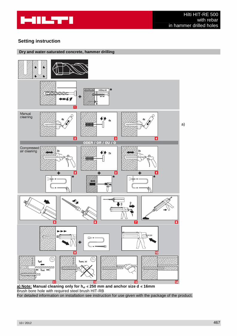
Hilti HIT-RE 500with rebar
in hammer drilled holes
10 / 2012 467
Setting instruction
Dry and water-saturated concrete, hammer drilling
a)
a) Note: Manual cleaning only for hef 250 mm and anchor size d 16mmBrush bore hole with required steel brush HIT-RBFor detailed information on installation see instruction for use given with the package of the product.

Hilti HIT-RE 500with rebarin hammer drilled holes
10 / 2012468
Water filled bore hole or submerged, hammer drilling
Brush bore hole with required steel brush HIT-RBFor detailed information on installation see instruction for use given with the package of the product.

Hilti HIT-RE 500with rebar
in hammer drilled holes
10 / 2012 469
Curing time for general conditions
Data according ETA-04/0027, issue 2009-05-20 AdditionalHilti technical data
Temperatureof the base material
Working time in which anchor
can be inserted and adjusted tgel
Curing time before anchor
can be fully loaded tcure
Preparation work may continue.
Do not apply design load. tcure, ini
40 °C 12 min 4 h 2 h30 °C to 39 °C 12 min 8 h 4 h20 °C to 29 °C 20 min 12 h 6 h15 °C to 19 °C 30 min 24 h 8 h10 °C to 14 °C 90 min 48 h 12 h
5 °C to 9 °C 120 min 72 h 18 h
For dry concrete curing times may be reduced according to the following table.For installation temperatures below +5 °C all load values have to be reduced according to the load reduction factors given below.
Curing time for dry concreteAdditional Hilti technical data
Temperatureof the
base material
Reduced curing time before anchor can be
fully loaded tcure,dry
Working time in which anchor can be inserted
and adjusted tgel
Load reduction factor
40 °C 4 h 12 min 130 °C 8 h 12 min 120 °C 12 h 20 min 115 °C 18 h 30 min 110 °C 24 h 90 min 15 °C 36 h 120 min 10 °C 50 h 3 h 0,7-5 °C 72 h 4 h 0,6

Hilti HIT-RE 500with rebarin hammer drilled holes
10 / 2012470
Setting details
Data according ETA-04/0027, issue 2009-05-20Additional Hilti tech.
dataAnchor size Ø8 Ø10 Ø12 Ø14 Ø16 Ø20 Ø25 Ø28 Ø32 Ø36 Ø40Nominal diameter of drill bit
d0 [mm] 12 14 16 18 20 25 32 35 40 45 55
Effective anchorage and drill hole depth range a)
hef,min [mm] 60 60 70 75 80 90 100 112 128 144 160
hef,max [mm] 160 200 240 280 320 400 500 560 640 720 800
Minimum base material thickness
hmin [mm]hef + 30 mm
hef + 2 d0
Minimum spacing smin [mm] 40 50 60 70 80 100 125 140 160 180 200Minimum edge distance
cmin [mm] 40 50 60 70 80 100 125 140 160 180 200
Critical spacing for splitting failure
scr,sp 2 ccr,sp
Critical edge distance for splitting failure b) ccr,sp [mm]
1,0 hef for h / hef
4,6 hef - 1,8 h for 2,0 > h / hef > 1,3
2,26 hef for h / hef 1,3
Critical spacing for concrete cone failure
scr,N 2 ccr,N
Critical edge distance for concrete cone failure c)
ccr,N 1,5 hef
For spacing (edge distance) smaller than critical spacing (critical edge distance) the design loads have to be reduced.
a) hef,min hef ef,max (hef: embedment depth)
b) h: base material thickness (h hmin)
c) The critical edge distance for concrete cone failure depends on the embedment depth hef and the design bond resistance. The simplified formula given in this table is on the save side.
Simplified design methodSimplified version of the design method according ETAG 001, TR 029. Design resistance according data given in ETA-04/0027, issue 2009-05-20.
Influence of concrete strengthInfluence of edge distanceInfluence of spacing

Hilti HIT-RE 500with rebar
in hammer drilled holes
10 / 2012 471
Valid for a group of two anchors. (The method may also be applied for anchor groups with more than two anchors or more than one edge distance. The influencing factors must then be considered for each edge distance and spacing. The calculated design loads are then on the save side: They will be lower than the exact values according ETAG 001, TR 029. To avoid this, it is recommended to use the anchor design software PROFIS anchor)
The design method is based on the following simplification:No different loads are acting on individual anchors (no eccentricity)
The values are valid for one anchor.
For more complex fastening applications please use the anchor design software PROFIS Anchor.
Tension loading
The design tensile resistance is the lower value of- Steel resistance: NRd,s
- Combined pull-out and concrete cone resistance:NRd,p = N0
Rd,p fB,p f1,N f2,N f3,N fh,p fre,N
- Concrete cone resistance: NRd,c = N0Rd,c fB f1,N f2,N f3,N fh,N fre,N
- Concrete splitting resistance (only non-cracked concrete):NRd,sp = N0
Rd,c fB f1,sp f2,sp f3,sp fh,N fre,N
Basic design tensile resistance
Design steel resistance NRd,s
Data according ETA-04/0027, issue 2009-05-20Additional Hilti tech.
dataAnchor size Ø8 Ø10 Ø12 Ø14 Ø16 Ø20 Ø25 Ø28 Ø32 Ø36 Ø40NRd,s BSt 500 S [kN] 20,0 30,7 44,3 60,7 79,3 123,6 192,9 242,1 315,7 400 494
Design combined pull-out and concrete cone resistance a)
NRd,p = N0Rd,p fB,p f1,N f2,N f3,N fh,p fre,N
Data according ETA-04/0027, issue 2009-05-20Additional Hilti tech.
dataAnchor size Ø8 Ø10 Ø12 Ø14 Ø16 Ø20 Ø25 Ø28 Ø32 Ø36 Ø40Typical embedment depthhef,typ [mm] 80 90 110 125 125 170 210 270 300 330 360
N0Rd,p Temperature range I [kN] 14,4 20,2 29,6 36,7 41,9 71,2 102,1 147,0 186,7 192,8 216,1
N0Rd,p Temperature range II [kN] 11,5 16,2 23,7 31,4 32,9 56,0 86,4 113,1 143,6 154,2 172,9
N0Rd,p Temperature range III [kN] 6,7 9,4 13,8 18,3 20,9 33,1 51,1 67,9 86,2 92,5 103,7
a) Additional Hilti technical data (not part of ETA-04/0027, issue 2009-05-20):The design values for combined pull-out and concrete cone resistance may be increased by 20 % for anchor installation in dry concrete (concrete not in contact with water before/during installation and curing).

Hilti HIT-RE 500with rebarin hammer drilled holes
10 / 2012472
Design concrete cone resistance a) NRd,c = N0Rd,c fB f1,N f2,N f3,N fh,N fre,N
Design splitting resistance NRd,spa) = N0
Rd,c fB f1,sp f2,sp f3,sp f h,N fre,N
Data according ETA-04/0027, issue 2009-05-20Additional Hilti tech.
dataAnchor size Ø8 Ø10 Ø12 Ø14 Ø16 Ø20 Ø25 Ø28 Ø32 Ø36 Ø40N0
Rd,c [kN] 17,2 20,5 27,7 33,6 33,6 53,3 73,2 106,7 125,0 144,2 164,3a) Additional Hilti technical data (not part of ETA-04/0027, issue 2009-05-20):
The design values for concrete cone and splitting resistance may be increased by 20 % for anchor installation in dry concrete (concrete not in contact with water before/during installation and curing).
Influencing factors
Influence of concrete strength on combined pull-out and concrete cone resistanceConcrete strength designation(ENV 206) C 20/25 C 25/30 C 30/37 C 35/45 C 40/50 C 45/55 C 50/60
fB,p = (fck,cube/25N/mm²)0,1 a) 1 1,02 1,04 1,06 1,07 1,08 1,09a) fck,cube = concrete compressive strength, measured on cubes with 150 mm side length
Influence of embedment depth on combined pull-out and concrete cone resistancefh,p = hef/hef,typ
Influence of concrete strength on concrete cone resistanceConcrete strength designation(ENV 206) C 20/25 C 25/30 C 30/37 C 35/45 C 40/50 C 45/55 C 50/60
fB = (fck,cube/25N/mm²)1/2 a) 1 1,1 1,22 1,34 1,41 1,48 1,55a) fck,cube = concrete compressive strength, measured on cubes with 150 mm side length
Influence of edge distance a)
c/ccr,N0,1 0,2 0,3 0,4 0,5 0,6 0,7 0,8 0,9 1
c/ccr,sp
f1,N = 0,7 + 0,3 c/ccr,N0,73 0,76 0,79 0,82 0,85 0,88 0,91 0,94 0,97 1
f1,sp = 0,7 + 0,3 c/ccr,sp
f2,N = 0,5 (1 + c/ccr,N)0,55 0,60 0,65 0,70 0,75 0,80 0,85 0,90 0,95 1
f2,sp = 0,5 (1 + c/ccr,sp)a) The the edge distance shall not be smaller than the minimum edge distance cmin given in the table with the
setting details. These influencing factors must be considered for every edge distance smaller than the critical edge distance.
Influence of anchor spacing a)
s/scr,N0,1 0,2 0,3 0,4 0,5 0,6 0,7 0,8 0,9 1
s/scr,sp
f3,N = 0,5 (1 + s/scr,N)0,55 0,60 0,65 0,70 0,75 0,80 0,85 0,90 0,95 1
f3,sp = 0,5 (1 + s/scr,sp)a) The anchor spacing shall not be smaller than the minimum anchor spacing smin given in the table with the
setting details. This influencing factor must be considered for every anchor spacing.

Hilti HIT-RE 500with rebar
in hammer drilled holes
10 / 2012 473
Influence of embedment depth on concrete cone resistancefh,N = (hef/hef,typ)
1,5
Influence of reinforcementhef [mm] 40 50 60 70 80 90
fre,N = 0,5 + hef 0,7 a) 0,75 a) 0,8 a) 0,85 a) 0,9 a) 0,95 a) 1a) This factor applies only for dense reinforcement. If in the area of anchorage there is reinforcement with a
spacing mm, then a factor fre = 1may be applied.
Shear loading
The design shear resistance is the lower value of
- Steel resistance: VRd,s
- Concrete pryout resistance: VRd,cp = k lower value of NRd,p and NRd,c
- Concrete edge resistance: VRd,c = V0Rd,c fB fß f h f4 f hef fc
Basic design shear resistance
Design steel resistance VRd,s
Data according ETA-04/0027, issue 2009-05-20
Additional Hilti
technical data
Anchor size Ø8 Ø10 Ø12 Ø14 Ø16 Ø20 Ø25 Ø28 Ø32 Ø36 Ø40VRd,s BSt 500 S [kN] 9,3 14,7 20,7 28,0 36,7 57,3 90,0 112,7 147,3 186,6 230,4
Design concrete pryout resistance VRd,cp = lower valuea) of k NRd,p and k NRd,c
k = 1 for hef < 60 mmk = 2 for hef
a) NRd,p: Design combined pull-out and concrete cone resistanceNRd,c: Design concrete cone resistance
Design concrete edge resistance VRd,c = V0Rd,c fB fß f h f4 f hef fc
Anchor size Ø8 Ø10 Ø12 Ø14 Ø16 Ø20 Ø25 Ø28 Ø32 Ø36 Ø40Non-cracked concreteV0
Rd,c [kN] 5,9 8,6 11,6 15,0 18,7 27,0 39,2 47,3 59,0 71,7 85,5

Hilti HIT-RE 500with rebarin hammer drilled holes
10 / 2012474
Influencing factors
Influence of concrete strengthConcrete strength designation(ENV 206) C 20/25 C 25/30 C 30/37 C 35/45 C 40/50 C 45/55 C 50/60
fB = (fck,cube/25N/mm²)1/2 a) 1 1,1 1,22 1,34 1,41 1,48 1,55a) fck,cube = concrete compressive strength, measured on cubes with 150 mm side length
Influence of angle between load applied and the direction perpendicular to the free edgeAngle ß 0° 10° 20° 30° 40° 50° 60° 70° 80° 90°
1f
1 1,01 1,05 1,13 1,24 1,40 1,64 1,97 2,32 2,50
Influence of base material thicknessh/c 0,15 0,3 0,45 0,6 0,75 0,9 1,05 1,2 1,35
f h = {h/(1,5 c)} 1/2 0,32 0,45 0,55 0,63 0,71 0,77 0,84 0,89 0,95 1,00
Influence of anchor spacing and edge distance a) for concrete edge resistance: f4
f4 = (c/hef)1,5 (1 + s / [3 c]) 0,5
c/hefSingle anchor
Group of two anchors s/hef
0,75 1,50 2,25 3,00 3,75 4,50 5,25 6,00 6,75 7,50 8,25 9,00 9,75 ����� �����0,50 0,35 0,27 0,35 0,35 0,35 0,35 0,35 0,35 0,35 0,35 0,35 0,35 0,35 0,35 0,35 0,350,75 0,65 0,43 0,54 0,65 0,65 0,65 0,65 0,65 0,65 0,65 0,65 0,65 0,65 0,65 0,65 0,651,00 1,00 0,63 0,75 0,88 1,00 1,00 1,00 1,00 1,00 1,00 1,00 1,00 1,00 1,00 1,00 1,001,25 1,40 0,84 0,98 1,12 1,26 1,40 1,40 1,40 1,40 1,40 1,40 1,40 1,40 1,40 1,40 1,401,50 1,84 1,07 1,22 1,38 1,53 1,68 1,84 1,84 1,84 1,84 1,84 1,84 1,84 1,84 1,84 1,841,75 2,32 1,32 1,49 1,65 1,82 1,98 2,15 2,32 2,32 2,32 2,32 2,32 2,32 2,32 2,32 2,322,00 2,83 1,59 1,77 1,94 2,12 2,30 2,47 2,65 2,83 2,83 2,83 2,83 2,83 2,83 2,83 2,832,25 3,38 1,88 2,06 2,25 2,44 2,63 2,81 3,00 3,19 3,38 3,38 3,38 3,38 3,38 3,38 3,382,50 3,95 2,17 2,37 2,57 2,77 2,96 3,16 3,36 3,56 3,76 3,95 3,95 3,95 3,95 3,95 3,952,75 4,56 2,49 2,69 2,90 3,11 3,32 3,52 3,73 3,94 4,15 4,35 4,56 4,56 4,56 4,56 4,563,00 5,20 2,81 3,03 3,25 3,46 3,68 3,90 4,11 4,33 4,55 4,76 4,98 5,20 5,20 5,20 5,203,25 5,86 3,15 3,38 3,61 3,83 4,06 4,28 4,51 4,73 4,96 5,18 5,41 5,63 5,86 5,86 5,863,50 6,55 3,51 3,74 3,98 4,21 4,44 4,68 4,91 5,14 5,38 5,61 5,85 6,08 6,31 6,55 6,553,75 7,26 3,87 4,12 4,36 4,60 4,84 5,08 5,33 5,57 5,81 6,05 6,29 6,54 6,78 7,02 7,264,00 8,00 4,25 4,50 4,75 5,00 5,25 5,50 5,75 6,00 6,25 6,50 6,75 7,00 7,25 7,50 7,754,25 8,76 4,64 4,90 5,15 5,41 5,67 5,93 6,18 6,44 6,70 6,96 7,22 7,47 7,73 7,99 8,254,50 9,55 5,04 5,30 5,57 5,83 6,10 6,36 6,63 6,89 7,16 7,42 7,69 7,95 8,22 8,49 8,754,75 10,35 5,45 5,72 5,99 6,27 6,54 6,81 7,08 7,36 7,63 7,90 8,17 8,45 8,72 8,99 9,265,00 11,18 5,87 6,15 6,43 6,71 6,99 7,27 7,55 7,83 8,11 8,39 8,66 8,94 9,22 9,50 9,785,25 12,03 6,30 6,59 6,87 7,16 7,45 7,73 8,02 8,31 8,59 8,88 9,17 9,45 9,74 10,02 10,315,50 12,90 6,74 7,04 7,33 7,62 7,92 8,21 8,50 8,79 9,09 9,38 9,67 9,97 10,26 10,55 10,85
a) The anchor spacing and the edge distance shall not be smaller than the minimum anchor spacing smin and the minimum edge distance cmin.

Hilti HIT-RE 500with rebar
in hammer drilled holes
10 / 2012 475
Influence of embedment depthhef/d 4 4,5 5 6 7 8 9 10 11
f hef = 0,05 (hef / d)1,68 0,51 0,63 0,75 1,01 1,31 1,64 2,00 2,39 2,81
hef/d 12 13 14 15 16 17 18 19 20
f hef = 0,05 (hef / d)1,68 3,25 3,72 4,21 4,73 5,27 5,84 6,42 7,04 7,67
Influence of edge distance a)
c/d 4 6 8 10 15 20 30 40
fc = (d / c)0,19 0,77 0,71 0,67 0,65 0,60 0,57 0,52 0,50a) The edge distance shall not be smaller than the minimum edge distance cmin.
Combined tension and shear loading
For combined tension and shear loading see section “Anchor Design”.
Precalculated valuesRecommended loads can be calculated by dividing the design resistance by an overall partial safety factor for action = 1,4. The partial safety factors for action depend on the type of loading and shall be taken from national regulations.

Hilti HIT-RE 500with rebarin hammer drilled holes
10 / 2012476
Design resistance: concrete C 20/25 – fck,cube = 25 N/mm², Temperature range I
Data according ETA-04/0027, issue 2009-05-20Additional Hilti tech.
dataAnchor size Ø8 Ø10 Ø12 Ø14 Ø16 Ø20 Ø25 Ø28 Ø32 Ø36 Ø40Embedment depth hef,1 = [mm] 60 60 72 84 96 120 150 168 192 216 240Base material thickness hmin= [mm] 100 100 104 120 136 170 214 238 272 306 350
Tensile NRd: single anchor, no edge effects
BSt 500 S [kN] 10,8 11,2 14,7 18,5 22,6 31,6 44,2 52,4 64,0 76,3 89,4
Shear VRd: single anchor, no edge effects, without lever arm
BSt 500 S [kN] 9,3 14,7 20,7 28,0 36,7 57,3 90,0 112,7 147,3 186,6 230,4
Design resistance: concrete C 20/25 – fck,cube = 25 N/mm², Temperature range I
Data according ETA-04/0027, issue 2009-05-20Additional Hilti tech.
dataAnchor size Ø8 Ø10 Ø12 Ø14 Ø16 Ø20 Ø25 Ø28 Ø32 Ø36 Ø40Embedment depth hef,1 = [mm] 60 60 72 84 96 120 150 168 192 216 240Base material thickness hmin= [mm] 100 100 104 120 136 170 214 238 272 306 350Edge distance c = cmin= [mm] 40 50 60 70 80 100 125 140 160 180 200
Tensile NRd: single anchor, min. edge distance (c = cmin)
BSt 500 S [kN] 6,5 7,3 8,6 10,8 13,1 18,3 25,6 30,3 37,0 44,1 52,5
Shear VRd: single anchor, min. edge distance (c = cmin) , without lever arm
BSt 500 S [kN] 3,5 4,9 6,7 8,6 10,8 15,7 22,9 27,7 34,6 42,2 50,4
Design resistance: concrete C 20/25 – fck,cube = 25 N/mm², Temperature range I(load values are valid for single anchor)
Data according ETA-04/0027, issue 2009-05-20Additional Hilti tech.
dataAnchor size Ø8 Ø10 Ø12 Ø14 Ø16 Ø20 Ø25 Ø28 Ø32 Ø36 Ø40Embedment depth hef,1 = [mm] 60 60 72 84 96 120 150 168 192 216 240Base material thickness hmin= [mm] 100 100 104 120 136 170 214 238 272 306 350Spacing s = smin= [mm] 40 50 60 70 80 100 125 140 160 180 200
Tensile NRd: double anchor, no edge effects, min. spacing (s = smin)
BSt 500 S [kN] 6,7 7,0 8,9 11,2 13,6 19,0 26,6 31,5 38,5 45,9 54,1
Shear VRd: double anchor, no edge effects, min. spacing (s = smin) , without lever arm
BSt 500 S [kN] 9,3 14,7 20,7 28,0 36,7 56,5 79,0 93,7 114,4 136,6 159,9
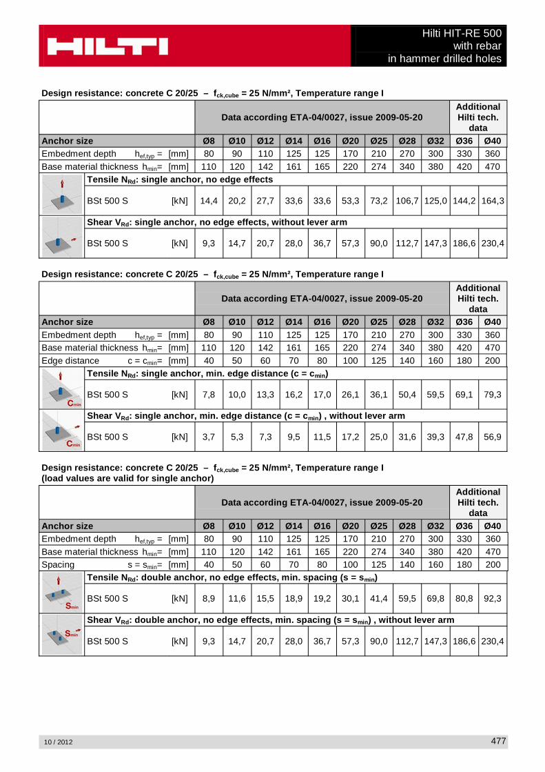
Hilti HIT-RE 500with rebar
in hammer drilled holes
10 / 2012 477
Design resistance: concrete C 20/25 – fck,cube = 25 N/mm², Temperature range I
Data according ETA-04/0027, issue 2009-05-20Additional Hilti tech.
dataAnchor size Ø8 Ø10 Ø12 Ø14 Ø16 Ø20 Ø25 Ø28 Ø32 Ø36 Ø40Embedment depth hef,typ = [mm] 80 90 110 125 125 170 210 270 300 330 360Base material thickness hmin= [mm] 110 120 142 161 165 220 274 340 380 420 470
Tensile NRd: single anchor, no edge effects
BSt 500 S [kN] 14,4 20,2 27,7 33,6 33,6 53,3 73,2 106,7 125,0 144,2 164,3
Shear VRd: single anchor, no edge effects, without lever arm
BSt 500 S [kN] 9,3 14,7 20,7 28,0 36,7 57,3 90,0 112,7 147,3 186,6 230,4
Design resistance: concrete C 20/25 – fck,cube = 25 N/mm², Temperature range I
Data according ETA-04/0027, issue 2009-05-20Additional Hilti tech.
dataAnchor size Ø8 Ø10 Ø12 Ø14 Ø16 Ø20 Ø25 Ø28 Ø32 Ø36 Ø40Embedment depth hef,typ = [mm] 80 90 110 125 125 170 210 270 300 330 360Base material thickness hmin= [mm] 110 120 142 161 165 220 274 340 380 420 470Edge distance c = cmin= [mm] 40 50 60 70 80 100 125 140 160 180 200
Tensile NRd: single anchor, min. edge distance (c = cmin)
BSt 500 S [kN] 7,8 10,0 13,3 16,2 17,0 26,1 36,1 50,4 59,5 69,1 79,3
Shear VRd: single anchor, min. edge distance (c = cmin) , without lever arm
BSt 500 S [kN] 3,7 5,3 7,3 9,5 11,5 17,2 25,0 31,6 39,3 47,8 56,9
Design resistance: concrete C 20/25 – fck,cube = 25 N/mm², Temperature range I(load values are valid for single anchor)
Data according ETA-04/0027, issue 2009-05-20Additional Hilti tech.
dataAnchor size Ø8 Ø10 Ø12 Ø14 Ø16 Ø20 Ø25 Ø28 Ø32 Ø36 Ø40Embedment depth hef,typ = [mm] 80 90 110 125 125 170 210 270 300 330 360Base material thickness hmin= [mm] 110 120 142 161 165 220 274 340 380 420 470Spacing s = smin= [mm] 40 50 60 70 80 100 125 140 160 180 200
Tensile NRd: double anchor, no edge effects, min. spacing (s = smin)
BSt 500 S [kN] 8,9 11,6 15,5 18,9 19,2 30,1 41,4 59,5 69,8 80,8 92,3
Shear VRd: double anchor, no edge effects, min. spacing (s = smin) , without lever arm
BSt 500 S [kN] 9,3 14,7 20,7 28,0 36,7 57,3 90,0 112,7 147,3 186,6 230,4

Hilti HIT-RE 500with rebarin hammer drilled holes
10 / 2012478
Design resistance: concrete C 20/25 – fck,cube = 25 N/mm², Temperature range I
Data according ETA-04/0027, issue 2009-05-20Additional Hilti tech.
dataAnchor size Ø8 Ø10 Ø12 Ø14 Ø16 Ø20 Ø25 Ø28 Ø32 Ø36 Ø40Embedment depth hef,2 = [mm] 96 120 144 168 192 240 300 336 384 432 480Base material thickness hmin= [mm] 126 150 176 204 232 290 364 406 464 522 590
Tensile NRd: single anchor, no edge effects
BSt 500 S [kN] 17,2 26,9 38,8 49,3 64,0 89,4 125,0 148,1 181,0 215,9 252,9
Shear VRd: single anchor, no edge effects, without lever arm
BSt 500 S [kN] 9,3 14,7 20,7 28,0 36,7 57,3 90,0 112,7 147,3 186,6 230,4
Design resistance: concrete C 20/25 – fck,cube = 25 N/mm², Temperature range I
Data according ETA-04/0027, issue 2009-05-20Additional Hilti tech.
dataAnchor size Ø8 Ø10 Ø12 Ø14 Ø16 Ø20 Ø25 Ø28 Ø32 Ø36 Ø40Embedment depth hef,2 = [mm] 96 120 144 168 192 240 300 336 384 432 480Base material thickness hmin= [mm] 126 150 176 204 232 290 364 406 464 522 590Edge distance c = cmin= [mm] 40 50 60 70 80 100 125 140 160 180 200
Tensile NRd: single anchor, min. edge distance (c = cmin)
BSt 500 S [kN] 9,4 14,1 18,6 23,4 28,6 40,0 55,9 66,2 80,9 96,6 113,1
Shear VRd: single anchor, min. edge distance (c = cmin) , without lever arm
BSt 500 S [kN] 3,9 5,7 7,8 10,2 12,9 18,9 27,8 33,9 42,6 52,3 62,7
Design resistance: concrete C 20/25 – fck,cube = 25 N/mm², Temperature range I(load values are valid for single anchor)
Data according ETA-04/0027, issue 2009-05-20Additional Hilti tech.
dataAnchor size Ø8 Ø10 Ø12 Ø14 Ø16 Ø20 Ø25 Ø28 Ø32 Ø36 Ø40Embedment depth hef,2 = [mm] 96 120 144 168 192 240 300 336 384 432 480Base material thickness hmin= [mm] 126 150 176 204 232 290 364 406 464 522 590Spacing s = smin= [mm] 40 50 60 70 80 100 125 140 160 180 200
Tensile NRd: double anchor, no edge effects, min. spacing (s = smin)
BSt 500 S [kN] 10,9 16,6 22,7 28,6 34,9 48,8 68,2 80,9 98,8 117,9 138,1
Shear VRd: double anchor, no edge effects, min. spacing (s = smin) , without lever arm
BSt 500 S [kN] 9,3 14,7 20,7 28,0 36,7 57,3 90,0 112,7 147,3 186,6 230,4

Hilti HIT-RE 500with rebar
in hammer drilled holes
10 / 2012 479

Hilti HIT-RE 500with rebarin diamond drilled holes
10 / 2012480
Hilti HIT-RE 500 with rebar in diamond drilled holesInjection mortar system Benefits
HiltiHIT-RE 500330 ml foil pack
(also available as 500 mland 1400 mlfoil pack)
- suitable for non-cracked concrete C 20/25 to C 50/60
- high loading capacity
- suitable for dry and water saturated concrete
-- large diameter applications
- long working time at elevated temperatures
- odourless epoxy
- embedment depth range:from 60 … 160 mm for Ø8to 128 … 640 mm for Ø32
Statik mixer
rebar BSt 500 S
ConcreteSmall edge
distance and spacing
Variable embedment
depth
Diamond drilledholes
PROFIS Anchor design
software
Basic loading data (for a single anchor)All data in this section applies to For details see Simplified design method- Correct setting (See setting instruction)- No edge distance and spacing influence- Steel failure- Base material thickness, as specified in the table- One typical embedment depth, as specified in the table- One anchor material, as specified in the tables- Concrete C 20/25, fck,cube = 25 N/mm²- Temperate range I
(min. base material temperature -40°C, max. long term/short term base material temperature: +24°C/40°C)- Installation temperature range +5°C to +40°C
Embedment depth a) and base material thickness for the basic loading data. Mean ultimate resistance, characteristic resistance, design resistance, recommended loads.Anchor size Ø8 Ø10 Ø12 Ø14 Ø16 Ø20 Ø25 Ø28 Ø32Typical embedment depth [mm] 80 90 110 125 125 170 210 270 300Base material thickness [mm] 110 120 145 165 165 220 275 340 380
a) The allowed range of embedment depth is shown in the setting details. The corresponding load values can be calculated according to the simplified design method.

Hilti HIT-RE 500with rebar
in diamond drilled holes
10 / 2012 481
Mean ultimate resistance: concrete C 20/25 – fck,cube = 25 N/mm², anchor rebar BSt 500SAnchor size Ø8 Ø10 Ø12 Ø14 Ø16 Ø20 Ø25 Ø28 Ø32
Tensile NRu,m BSt 500 S [kN] 29,4 45,0 65,1 83,9 87,6 134,7 197,1 268,0 320,3
Shear VRu,m BSt 500 S [kN] 14,7 23,1 32,6 44,1 57,8 90,3 141,8 177,5 232,1
Characteristic resistance: concrete C 20/25 – fck,cube = 25 N/mm², anchor rebar BSt 500 SAnchor size Ø8 Ø10 Ø12 Ø14 Ø16 Ø20 Ø25 Ø28 Ø32
Tensile NRk BSt 500 S [kN] 24,1 33,9 49,8 63,2 66,0 101,5 148,4 201,9 241,3
Shear VRk BSt 500 S [kN] 14,0 22,0 31,0 42,0 55,0 86,0 135,0 169,0 221,0
Design resistance: concrete C 20/25 – fck,cube = 25 N/mm², anchor rebar BSt 500 SAnchor size Ø8 Ø10 Ø12 Ø14 Ø16 Ø20 Ø25 Ø28 Ø32
Tensile NRd BSt 500 S [kN] 13,4 18,8 27,6 30,1 31,4 48,3 70,7 96,1 114,9
Shear VRd BSt 500 S [kN] 9,3 14,7 20,7 28,0 36,7 57,3 90,0 112,7 147,3
Recommended loads a): concrete C 20/25 – fck,cube = 25 N/mm², anchor rebar BSt 500 SAnchor size Ø8 Ø10 Ø12 Ø14 Ø16 Ø20 Ø25 Ø28 Ø32
Tensile Nrec BSt 500 S [kN] 9,6 13,5 19,7 21,5 22,4 34,5 50,5 68,7 82,1
Shear Vrec BSt 500 S [kN] 6,7 10,5 14,8 20,0 26,2 41,0 64,3 80,5 105,2
a) With overall partial safety factor for action = 1,4. The partial safety factors for action depend on the type of loading and shall be taken from national regulations.
Service temperature rangeHilti HIT-RE 500 injection mortar may be applied in the temperature ranges given below. An elevated base material temperature may lead to a reduction of the design bond resistance.
Temperature range Base material temperature
Maximum long term base material temperature
Maximum short term base material temperature
Temperature range I -40 °C to +40 °C +24 °C +40 °CTemperature range II -40 °C to +58 °C +35 °C +58 °CTemperature range III -40 °C to +70 °C +43 °C +70 °C
Max short term base material temperatureShort-term elevated base material temperatures are those that occur over brief intervals, e.g. as a result of diurnal cycling.
Max long term base material temperatureLong-term elevated base material temperatures are roughly constant over significant periods of time.

Hilti HIT-RE 500with rebarin diamond drilled holes
10 / 2012482
Materials
Mechanical properties of rebar BSt 500SAnchor size Ø8 Ø10 Ø12 Ø14 Ø16 Ø20 Ø25 Ø28 Ø32Nominal tensile strength fuk
BSt 500 S [N/mm²] 550 550 550 550 550 550 550 550 550
Yield strength fyk
BSt 500 S [N/mm²] 500 500 500 500 500 500 500 500 500
Stressed cross-section As
BSt 500 S [mm²] 50,3 78,5 113,1 153,9 201,1 314,2 490,9 615,8 804,2
Moment of resistance W
BSt 500 S [mm³] 50,3 98,2 169,6 269,4 402,1 785,4 1534 2155 3217
Material qualityPart MaterialrebarBSt 500 S
Geometry and mechanical properties according to DIN 488-2:1986 or E DIN 488-2:2006
Setting
installation equipmentAnchor size Ø8 Ø10 Ø12 Ø14 Ø16 Ø20 Ø25 Ø28 Ø32Drilling tools DD EC-1, DD 100 … DD xxxOther tools compressed air gun or blow out pump, set of cleaning brushes, dispenser
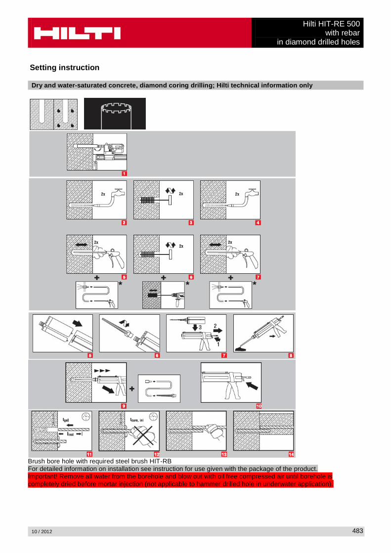
Hilti HIT-RE 500with rebar
in diamond drilled holes
10 / 2012 483
Setting instruction
Dry and water-saturated concrete, diamond coring drilling; Hilti technical information only
Brush bore hole with required steel brush HIT-RBFor detailed information on installation see instruction for use given with the package of the product.Important! Remove all water from the borehole and blow out with oil free compressed air until borehole is completely dried before mortar injection (not applicable to hammer drilled hole in underwater application).

Hilti HIT-RE 500with rebarin diamond drilled holes
10 / 2012484
Curing time for general conditionsTemperature
of the base materialWorking time in which
anchorcan be inserted and
adjusted tgel
Curing time before anchor
can be fully loaded tcure
Preparation work may continue.
Do not apply design load. tcure, ini
40 °C 12 min 4 h 2 h30 °C to 39 °C 12 min 8 h 4 h20 °C to 29 °C 20 min 12 h 6 h15 °C to 19 °C 30 min 24 h 8 h10 °C to 14 °C 90 min 48 h 12 h
5 °C to 9 °C 120 min 72 h 18 h
Setting detailsAnchor size Ø8 Ø10 Ø12 Ø14 Ø16 Ø20 Ø25 Ø28 Ø32Nominal diameter of drill bit
d0 [mm] 12 14 16 18 20 25 32 35 40
Effective anchorage and drill hole depth range a)
hef,min [mm] 60 60 70 75 80 90 100 112 128
hef,max [mm] 160 200 240 280 320 400 500 560 640
Minimum base material thickness
hmin [mm]hef + 30 mm
hef + 2 d0
Minimum spacing smin [mm] 40 50 60 70 80 100 125 140 160Minimum edge distance
cmin [mm] 40 50 60 70 80 100 125 140 160
Critical spacing for splitting failure
scr,sp 2 ccr,sp
Critical edge distance for splitting failure b) ccr,sp [mm]
1,0 hef for h / hef
4,6 hef - 1,8 h for 2,0 > h / hef > 1,3:
2,26 hef for h / hef 1,3:
Critical spacing for concrete cone failure
scr,N 2 ccr,N
Critical edge distance for concrete cone failure c)
ccr,N 1,5 hef
For spacing (edge distance) smaller than critical spacing (critical edge distance) the design loads have to be reduced.
a) hef,min hef ef,max (hef: embedment depth)
b) h: base material thickness (h hmin)
c) The critical edge distance for concrete cone failure depends on the embedment depth hef and the design bond resistance. The simplified formula given in this table is on the save side.

Hilti HIT-RE 500with rebar
in diamond drilled holes
10 / 2012 485
Simplified design methodSimplified version of the design method according ETAG 001, TR 029.
Influence of concrete strengthInfluence of edge distanceInfluence of spacingValid for a group of two anchors. (The method may also be applied for anchor groups with more than two anchors or more than one edge distance. The influencing factors must then be considered for each edge distance and spacing. The calculated design loads are then on the save side: They will be lower than the exact values according ETAG 001, TR 029. To avoid this, it is recommended to use the anchor design software PROFIS anchor)
The design method is based on the following simplification:No different loads are acting on individual anchors (no eccentricity)
The values are valid for one anchor.
For more complex fastening applications please use the anchor design software PROFIS Anchor.
Tension loading
The design tensile resistance is the lower value of- Steel resistance: NRd,s
- Combined pull-out and concrete cone resistance:NRd,p = N0
Rd,p fB,p f1,N f2,N f3,N fh,p fre,N
- Concrete cone resistance: NRd,c = N0Rd,c fB f1,N f2,N f3,N fh,N fre,N
- Concrete splitting resistance (only non-cracked concrete):NRd,sp = N0
Rd,c fB f1,sp f2,sp f3,sp fh,N fre,N
Basic design tensile resistance
Design steel resistance NRd,s
Anchor size Ø8 Ø10 Ø12 Ø14 Ø16 Ø20 Ø25 Ø28 Ø32NRd,s BSt 500 S [kN] 20,0 30,7 44,3 60,7 79,3 123,6 192,9 242,1 315,7
Design combined pull-out and concrete cone resistanceNRd,p = N0
Rd,p fB,p f1,N f2,N f3,N fh,p fre,N
Anchor size Ø8 Ø10 Ø12 Ø14 Ø16 Ø20 Ø25 Ø28 Ø32Typical embedment depthhef,typ [mm] 80 90 110 125 125 170 210 270 300
N0Rd,p Temperature range I [kN] 13,4 18,8 27,6 30,1 31,4 48,3 70,7 96,1 114,9
N0Rd,p Temperature range II [kN] 10,9 15,3 22,4 24,4 25,4 39,1 57,3 77,9 93,1
N0Rd,p Temperature range III [kN] 6,8 9,6 14,0 15,3 15,9 24,5 35,9 48,8 58,3
Design concrete cone resistance NRd,c = N0Rd,c fB f1,N f2,N f3,N fh,N fre,N
Design splitting resistance = N0Rd,c fB f1,sp f2,sp f3,sp f h,N fre,N
Anchor size Ø8 Ø10 Ø12 Ø14 Ø16 Ø20 Ø25 Ø28 Ø32N0
Rd,c [kN] 17,2 20,5 27,7 33,6 33,6 53,3 73,2 106,7 125,0

Hilti HIT-RE 500with rebarin diamond drilled holes
10 / 2012486
Influencing factors
Influence of concrete strength on combined pull-out and concrete cone resistanceConcrete strength designation(ENV 206) C 20/25 C 25/30 C 30/37 C 35/45 C 40/50 C 45/55 C 50/60
fB,p = (fck,cube/25N/mm²)0,1 a) 1 1,02 1,04 1,06 1,07 1,08 1,09a) fck,cube = concrete compressive strength, measured on cubes with 150 mm side length
Influence of embedment depth on combined pull-out and concrete cone resistancefh,p = hef/hef,typ
Influence of concrete strength on concrete cone resistanceConcrete strength designation(ENV 206) C 20/25 C 25/30 C 30/37 C 35/45 C 40/50 C 45/55 C 50/60
fB = (fck,cube/25N/mm²)1/2 a) 1 1,1 1,22 1,34 1,41 1,48 1,55a) fck,cube = concrete compressive strength, measured on cubes with 150 mm side length
Influence of edge distance a)
c/ccr,N0,1 0,2 0,3 0,4 0,5 0,6 0,7 0,8 0,9 1
c/ccr,sp
f1,N = 0,7 + 0,3 c/ccr,N0,73 0,76 0,79 0,82 0,85 0,88 0,91 0,94 0,97 1
f1,sp = 0,7 + 0,3 c/ccr,sp
f2,N = 0,5 (1 + c/ccr,N)0,55 0,60 0,65 0,70 0,75 0,80 0,85 0,90 0,95 1
f2,sp = 0,5 (1 + c/ccr,sp)a) The the edge distance shall not be smaller than the minimum edge distance cmin given in the table with the
setting details. These influencing factors must be considered for every edge distance smaller than the critical edge distance.
Influence of anchor spacing a)
s/scr,N0,1 0,2 0,3 0,4 0,5 0,6 0,7 0,8 0,9 1
s/scr,sp
f3,N = 0,5 (1 + s/scr,N)0,55 0,60 0,65 0,70 0,75 0,80 0,85 0,90 0,95 1
f3,sp = 0,5 (1 + s/scr,sp)a) The anchor spacing shall not be smaller than the minimum anchor spacing smin given in the table with the
setting details. This influencing factor must be considered for every anchor spacing.
Influence of embedment depth on concrete cone resistancefh,N = (hef/hef,typ)
1,5
Influence of reinforcementhef [mm] 40 50 60 70 80 90
fre,N = 0,5 + hef 0,7 a) 0,75 a) 0,8 a) 0,85 a) 0,9 a) 0,95 a) 1a) This factor applies only for dense reinforcement. If in the area of anchorage there is reinforcement with a
spacing mm, then a factor fre = 1may be applied.

Hilti HIT-RE 500with rebar
in diamond drilled holes
10 / 2012 487
Shear loading
The design shear resistance is the lower value of- Steel resistance: VRd,s
- Concrete pryout resistance: VRd,cp = k lower value of NRd,p and NRd,c
- Concrete edge resistance: VRd,c = V0Rd,c fB fß f h f4 f hef fc
Basic design shear resistance
Design steel resistance VRd,s
Anchor size Ø8 Ø10 Ø12 Ø14 Ø16 Ø20 Ø25 Ø28 Ø32VRd,s BSt 500 S [kN] 9,3 14,7 20,7 28,0 36,7 57,3 90,0 112,7 147,3
Design concrete pryout resistance VRd,cp = lower valuea) of k NRd,p and k NRd,c
k = 1 for hef < 60 mm
k = 2 for hef
a) NRd,p: Design combined pull-out and concrete cone resistanceNRd,c: Design concrete cone resistance
Design concrete edge resistance VRd,c = V0Rd,c fB fß f h f4 f hef fc
Anchor size Ø8 Ø10 Ø12 Ø14 Ø16 Ø20 Ø25 Ø28 Ø32 Ø36 Ø40Non-cracked concreteV0
Rd,c [kN] 5,9 8,6 11,6 15,0 18,7 27,0 39,2 47,3 59,0 71,7 85,5
Influencing factors
Influence of concrete strengthConcrete strength designation(ENV 206) C 20/25 C 25/30 C 30/37 C 35/45 C 40/50 C 45/55 C 50/60
fB = (fck,cube/25N/mm²)1/2 a) 1 1,1 1,22 1,34 1,41 1,48 1,55a) fck,cube = concrete compressive strength, measured on cubes with 150 mm side length
Influence of angle between load applied and the direction perpendicular to the free edgeAngle ß 0° 10° 20° 30° 40° 50° 60° 70° 80° 90°
1f
1 1,01 1,05 1,13 1,24 1,40 1,64 1,97 2,32 2,50
Influence of base material thicknessh/c 0,15 0,3 0,45 0,6 0,75 0,9 1,05 1,2 1,35
f h = {h/(1,5 c)} 1/2 0,32 0,45 0,55 0,63 0,71 0,77 0,84 0,89 0,95 1,00

Hilti HIT-RE 500with rebarin diamond drilled holes
10 / 2012488
Influence of anchor spacing and edge distance a) for concrete edge resistance: f4
f4 = (c/hef)1,5 (1 + s / [3 c]) 0,5
c/hefSingle anchor
Group of two anchors s/hef
0,75 1,50 2,25 3,00 3,75 4,50 5,25 6,00 6,75 7,50 8,25 9,00 9,75 ����� �����0,50 0,35 0,27 0,35 0,35 0,35 0,35 0,35 0,35 0,35 0,35 0,35 0,35 0,35 0,35 0,35 0,350,75 0,65 0,43 0,54 0,65 0,65 0,65 0,65 0,65 0,65 0,65 0,65 0,65 0,65 0,65 0,65 0,651,00 1,00 0,63 0,75 0,88 1,00 1,00 1,00 1,00 1,00 1,00 1,00 1,00 1,00 1,00 1,00 1,001,25 1,40 0,84 0,98 1,12 1,26 1,40 1,40 1,40 1,40 1,40 1,40 1,40 1,40 1,40 1,40 1,401,50 1,84 1,07 1,22 1,38 1,53 1,68 1,84 1,84 1,84 1,84 1,84 1,84 1,84 1,84 1,84 1,841,75 2,32 1,32 1,49 1,65 1,82 1,98 2,15 2,32 2,32 2,32 2,32 2,32 2,32 2,32 2,32 2,322,00 2,83 1,59 1,77 1,94 2,12 2,30 2,47 2,65 2,83 2,83 2,83 2,83 2,83 2,83 2,83 2,832,25 3,38 1,88 2,06 2,25 2,44 2,63 2,81 3,00 3,19 3,38 3,38 3,38 3,38 3,38 3,38 3,382,50 3,95 2,17 2,37 2,57 2,77 2,96 3,16 3,36 3,56 3,76 3,95 3,95 3,95 3,95 3,95 3,952,75 4,56 2,49 2,69 2,90 3,11 3,32 3,52 3,73 3,94 4,15 4,35 4,56 4,56 4,56 4,56 4,563,00 5,20 2,81 3,03 3,25 3,46 3,68 3,90 4,11 4,33 4,55 4,76 4,98 5,20 5,20 5,20 5,203,25 5,86 3,15 3,38 3,61 3,83 4,06 4,28 4,51 4,73 4,96 5,18 5,41 5,63 5,86 5,86 5,863,50 6,55 3,51 3,74 3,98 4,21 4,44 4,68 4,91 5,14 5,38 5,61 5,85 6,08 6,31 6,55 6,553,75 7,26 3,87 4,12 4,36 4,60 4,84 5,08 5,33 5,57 5,81 6,05 6,29 6,54 6,78 7,02 7,264,00 8,00 4,25 4,50 4,75 5,00 5,25 5,50 5,75 6,00 6,25 6,50 6,75 7,00 7,25 7,50 7,754,25 8,76 4,64 4,90 5,15 5,41 5,67 5,93 6,18 6,44 6,70 6,96 7,22 7,47 7,73 7,99 8,254,50 9,55 5,04 5,30 5,57 5,83 6,10 6,36 6,63 6,89 7,16 7,42 7,69 7,95 8,22 8,49 8,754,75 10,35 5,45 5,72 5,99 6,27 6,54 6,81 7,08 7,36 7,63 7,90 8,17 8,45 8,72 8,99 9,265,00 11,18 5,87 6,15 6,43 6,71 6,99 7,27 7,55 7,83 8,11 8,39 8,66 8,94 9,22 9,50 9,785,25 12,03 6,30 6,59 6,87 7,16 7,45 7,73 8,02 8,31 8,59 8,88 9,17 9,45 9,74 10,02 10,315,50 12,90 6,74 7,04 7,33 7,62 7,92 8,21 8,50 8,79 9,09 9,38 9,67 9,97 10,26 10,55 10,85
a) The anchor spacing and the edge distance shall not be smaller than the minimum anchor spacing smin and the minimum edge distance cmin.
Influence of embedment depthhef/d 4 4,5 5 6 7 8 9 10 11
f hef = 0,05 (hef / d)1,68 0,51 0,63 0,75 1,01 1,31 1,64 2,00 2,39 2,81
hef/d 12 13 14 15 16 17 18 19 20
f hef = 0,05 (hef / d)1,68 3,25 3,72 4,21 4,73 5,27 5,84 6,42 7,04 7,67
Influence of edge distance a)
c/d 4 6 8 10 15 20 30 40
fc = (d / c)0,19 0,77 0,71 0,67 0,65 0,60 0,57 0,52 0,50a) The edge distance shall not be smaller than the minimum edge distance cmin.
Combined tension and shear loading
For combined tension and shear loading see section “Anchor Design”.